WO2015020134A1 - 身体の動作に基づく制御指令生成方法及び制御指令生成装置 - Google Patents
身体の動作に基づく制御指令生成方法及び制御指令生成装置 Download PDFInfo
- Publication number
- WO2015020134A1 WO2015020134A1 PCT/JP2014/070831 JP2014070831W WO2015020134A1 WO 2015020134 A1 WO2015020134 A1 WO 2015020134A1 JP 2014070831 W JP2014070831 W JP 2014070831W WO 2015020134 A1 WO2015020134 A1 WO 2015020134A1
- Authority
- WO
- WIPO (PCT)
- Prior art keywords
- motion
- angle
- axis
- control command
- finger
- Prior art date
- Legal status (The legal status is an assumption and is not a legal conclusion. Google has not performed a legal analysis and makes no representation as to the accuracy of the status listed.)
- Ceased
Links
Images






















Classifications
-
- B—PERFORMING OPERATIONS; TRANSPORTING
- B25—HAND TOOLS; PORTABLE POWER-DRIVEN TOOLS; MANIPULATORS
- B25J—MANIPULATORS; CHAMBERS PROVIDED WITH MANIPULATION DEVICES
- B25J13/00—Controls for manipulators
-
- B—PERFORMING OPERATIONS; TRANSPORTING
- B25—HAND TOOLS; PORTABLE POWER-DRIVEN TOOLS; MANIPULATORS
- B25J—MANIPULATORS; CHAMBERS PROVIDED WITH MANIPULATION DEVICES
- B25J13/00—Controls for manipulators
- B25J13/02—Hand grip control means
-
- B—PERFORMING OPERATIONS; TRANSPORTING
- B25—HAND TOOLS; PORTABLE POWER-DRIVEN TOOLS; MANIPULATORS
- B25J—MANIPULATORS; CHAMBERS PROVIDED WITH MANIPULATION DEVICES
- B25J9/00—Program-controlled manipulators
- B25J9/16—Program controls
- B25J9/1679—Program controls characterised by the tasks executed
- B25J9/1689—Teleoperation
-
- G—PHYSICS
- G05—CONTROLLING; REGULATING
- G05B—CONTROL OR REGULATING SYSTEMS IN GENERAL; FUNCTIONAL ELEMENTS OF SUCH SYSTEMS; MONITORING OR TESTING ARRANGEMENTS FOR SUCH SYSTEMS OR ELEMENTS
- G05B2219/00—Program-control systems
- G05B2219/30—Nc systems
- G05B2219/35—Nc in input of data, input till input file format
- G05B2219/35444—Gesture interface, controlled machine observes operator, executes commands
-
- G—PHYSICS
- G05—CONTROLLING; REGULATING
- G05B—CONTROL OR REGULATING SYSTEMS IN GENERAL; FUNCTIONAL ELEMENTS OF SUCH SYSTEMS; MONITORING OR TESTING ARRANGEMENTS FOR SUCH SYSTEMS OR ELEMENTS
- G05B2219/00—Program-control systems
- G05B2219/30—Nc systems
- G05B2219/40—Robotics, robotics mapping to robotics vision
- G05B2219/40309—Simulation of human hand motion
Definitions
- the present invention relates to a control command generation method and a control command generation device based on body motion, and more particularly to a method and device for generating a control command based on body motion.
- the control target may operate out of the operator's intention. That is, the operator's intention may not be accurately reflected in the control command generated to control the operation of the controlled object.
- the present invention intends to provide a control command generation method and a control command generation device that can generate a control command in which an operator's intention is accurately reflected, based on body movements. .
- the present invention provides a control command generation method based on body movements configured as follows.
- the control command generation method based on body motion associates a reference motion for moving a body reference region in a reference direction with a control command, and generates the control command based on the motion of the reference region.
- a control command generation method based on body movement includes first to third steps.
- a mathematical formula or database is prepared for associating the first action including the reference action with the second action that is the actual action of the reference part corresponding to the first action.
- the movement of the reference portion of the operator is measured.
- the operation measured in the second step is used as the first operation by using the mathematical formula or the database as the second operation.
- the control command is calculated based on the component of the reference motion included in the converted first motion.
- a common mathematical expression or database may be prepared for a plurality of operators, or a separate mathematical expression or database may be prepared individually, that is, for each operator. If separate mathematical formulas or databases are prepared individually, that is, for each operator, the movement characteristics of each operator's body are reflected more accurately than when a common mathematical formula or database is prepared for a plurality of operators. Therefore, it is possible to generate a control command that more accurately reflects the intention of each operator.
- the measurement of the movement of the reference part is not only a method of directly measuring the movement of the reference part, but also an indirect calculation of the movement of the reference part from the movement of another part that moves in conjunction with the reference part. It may be a simple method.
- the present invention provides a control command generation method based on body movements configured as follows in order to solve the above-described problems.
- the control command generation method based on body motion associates a reference motion for moving a body reference region in a reference direction with a control command, and generates the control command based on the motion of the reference region.
- a control command generation method based on body movement includes first to third steps.
- a mathematical formula or database is prepared for associating the first action including the reference action with the second action that is the actual action of the reference part corresponding to the first action.
- data obtained by measuring an operation of the reference portion of the operator is acquired.
- the operation that acquired the data in the second step by using the mathematical formula or the database as the second operation for the operation that acquired the data in the second step. Is converted into the first operation, and the control command is calculated based on the reference operation component included in the converted first operation.
- the mathematical formula or the database prepared in the first step is one of the variables.
- the first motion including the motion element of the reference part, in which only one changes, and the second motion including a motion component in which a plurality of the variables change corresponding to the motion element are associated with each other. .
- the operation characteristics of the reference part can be reflected in the mathematical formula or database.
- the reference portion is included in at least one of the lower limb, the upper limb, the neck and the head. More preferably, the reference portion is included in at least one of the lower limbs on the foot side from the knee joint and the upper limbs on the hand side from the elbow joint.
- the reference direction for operating the reference part in the reference movement includes at least one of the front-rear direction, the left-right direction, and the up-down direction of the body defined based on a posture that is a basis of the body. .
- the operator can intuitively recognize the front-rear direction, the left-right direction, and the up-down direction of the body and can recognize even when the body is in an oblique posture with respect to the gravity direction.
- the operation to do is easy.
- the reference direction in which the reference portion is operated in the reference operation includes at least one of a gravity direction and a horizontal direction perpendicular to the gravity direction.
- the reference direction for operating the reference part in the reference movement is a linear direction or a rotation direction defined by a coordinate system integrally fixed to a part of the body different from the reference part. Including at least one.
- the relative movement of the reference part viewed from a part different from the reference part can be used to define the reference direction.
- the “coordinate system that is integrally fixed to a part of the body that is different from the reference part” is not limited to one that is directly fixed to the part. Including those fixed at virtual positions.
- the reference site is included in the lower limb.
- the operator includes a first posture in which the lower leg of the lower limb including the reference region is substantially parallel to the vertical direction of the body, and the lower limb thigh including the reference region.
- the reference part is operated based on a posture including at least one of the second postures substantially parallel to the front-rear direction of the body.
- substantially parallel means that the deviation from parallel or parallel is within ⁇ 40 degrees, and more preferably, the deviation from parallel or parallel is within ⁇ 10 degrees.
- the reference portion is included in the upper limb.
- the operator has a first posture in which the upper arm of the upper limb including the reference region is substantially parallel to the vertical direction of the body, and a forearm of the upper limb including the reference region.
- the reference part is operated based on a posture including at least one of the second postures substantially parallel to the front-rear direction of the body.
- substantially parallel means that the deviation from parallel or parallel is within ⁇ 40 degrees, and more preferably, the deviation from parallel or parallel is within ⁇ 10 degrees.
- the mathematical formula or the database is derived by applying regression analysis to a measured value obtained by measuring the first action and the second action corresponding to the first action in association with each other.
- the regression analysis includes single regression analysis and multiple regression analysis.
- the mathematical expression or the database associating the first motion including a motion component in which the reference portion linearly moves with the second motion corresponding to the first motion corresponds to the motion component.
- the second motion component is a mathematical formula or database that incorporates the curve motion of the reference portion.
- Arc motion also corresponds to curved motion.
- the reference part is a part on the foot side from the knee joint.
- the mathematical expression or the database associating the first motion including a linear motion component in which the reference portion linearly moves in the front-rear direction of the body and the second motion corresponding to the first motion is the linear motion.
- the curve of the reference portion bent so that the knee joint side is inward when the component of the second motion corresponding to the component is viewed in a direction parallel to the rotation center axis of the bending and stretching motion of the knee joint. It is a mathematical formula or database that incorporates the fact that it becomes an exercise.
- the reference part is a part on the foot side from the knee joint.
- the mathematical expression or the database associating the first motion including a linear motion component in which the reference portion linearly moves in the left-right direction of the body and the second motion corresponding to the first motion is the linear motion.
- the second motion component corresponding to the component is bent so that the knee joint side is inward when viewed in a direction parallel to the axis connecting the hip joint of the lower limb including the knee joint and the knee joint.
- a curved motion including at least one of the first curved motion of the reference portion and the second curved motion of the reference portion bent so that the hip joint side is inward when viewed from above the body; It is a mathematical formula or database that incorporates
- the reference part is a part on the foot side from the knee joint.
- the mathematical expression or the database associating the first motion including a linear motion component in which the reference portion linearly moves in the vertical direction of the body and the second motion corresponding to the first motion is the linear motion.
- the component of the second motion corresponding to the component is a plane parallel to the vertical direction of the body and is perpendicular to the plane including the hip joint of the lower limb including the knee joint and the knee joint.
- the curve of the reference portion bent so that the position downward from the hip joint is the inside by a distance corresponding to the vertical component of the line segment connecting the knee joint and the reference portion.
- the reference region is included in the lower leg on the right side of the body.
- the hip joint center of the lower limb as the origin, the axis parallel to the left-right direction of the body and the direction from the left side to the right side of the body as the positive direction is the x axis, and
- the hip joint center is the origin.
- the (k) the comprises x k axis and a plane parallel to the z-axis from The ankle perpendicular foot that beat from the center P 3, an axis and (l) said the knee joint center as the origin, the axis passing through the ankle center, the direction toward the ankle center from the knee joint center forward K O3 axis, (m) the knee joint center as an origin, said at axis through the P 3, the knee joint center from K P3 axis an axis direction as the positive direction toward the P 3, (n) the r An angle formed by the positive direction of the axis and the positive direction of the z k axis is the angle A, (o) an angle formed by the positive direction of the y k axis and the positive direction of the K P2 axis is the angle B, (p) angular positive direction and the positive direction angle of the r-axis of y-axis C, and is defined as (q
- x k-axis, y k-axis, z k axis is a right-handed coordinate system with its origin at the knee joint center.
- the amount of change in the angles A, B, C, and D has positive and negative values corresponding to the increase and decrease.
- the reference region is included in the lower leg of the left side of the body.
- the hip joint center of the lower limb as the origin, the axis parallel to the left-right direction of the body and the direction from the right side to the left side of the body as the positive direction is the x axis, and
- the hip joint center is the origin.
- the K O3 axis (m) the knee joint center as the origin, the axis passing through the P 3, the knee joint center from K P3 axis an axis direction as the positive direction toward the P 3, (n) the The angle formed by the positive direction of the r axis and the positive direction of the z k axis is the angle A, (o) The angle formed by the positive direction of the y k axis and the positive direction of the K P2 axis is the angle B, (p) the y-axis positive direction is a positive direction and angular the angle formed C of the r-axis and is defined as (q) the K O3 forward direction as the K P3 corner D in the positive direction and the angle between the axis of the shaft,
- the equation or the database variable includes the angle A, the angle B, the angle C, the angle D, the amount of change of the angle A, the amount of change of the angle B, Variation of the serial angle C, and comprises at least one of the amount of change in the angle
- x k-axis, y k-axis, z k axis is the left-hand coordinate system with its origin at the knee joint center.
- the amount of change in the angles A, B, C, and D has positive and negative values corresponding to the increase and decrease.
- the amount of change in the coordinate value of the x-axis of the first action and the amount of change in the angle B of the second action A set, a set of a change amount of the coordinate value of the x-axis of the first operation and a change amount of the angle C of the second operation, and a change amount of the coordinate value of the z-axis of the first operation
- a set, a set of a change amount of the angle A of the second operation a set of a change amount of the coordinate value of the y-axis of the first operation and a change amount of the angle D of the second operation.
- At least one pair is in a proportional relationship.
- the “coordinate value of the x-axis of the first motion” is a coordinate value representing the position of the reference part in the first motion, and is a coordinate value represented using the x-axis.
- the “coordinate value of the z-axis of the first operation” is a coordinate value representing the position of the reference part in the first operation, and means a coordinate value expressed using the z-axis.
- the “coordinate value of the y-axis of the first motion” is a coordinate value representing the position of the reference part in the first motion, and means a coordinate value represented using the y-axis.
- the mathematical formula associating the first motion including a rotational motion component in which the reference portion rotationally moves with the first axis as a rotation center axis and the second motion corresponding to the first motion, or
- the second motion component corresponding to the rotational motion component is different from the first rotational motion of the reference portion having the first axis as the rotational center axis and the first axis. It is a mathematical formula or database that incorporates the second rotational movement of the reference portion with the second axis as the rotation center axis.
- the reference site is a foot of the lower limbs.
- the angle at which the foot is abducted or abducted is defined as an opening angle.
- the mathematical formula or the database includes the opening angle as the variable of the first motion,
- the movement angle includes the opening angle and the elevation angle, and the increase of the opening angle that is the variable of the first movement, the increase of the opening angle that is the variable of the second movement, and the second
- a second characteristic that correlates with a decrease in the elevation angle that is a variable of the second action Chi has at least one.
- the reference site is a foot of the lower limbs.
- the angle at which the foot is abducted or inverted is defined as an opening angle, and the opening angle increases from the inversion side to the abduction side of the foot, and the angle at which the foot is varus or valgus is an inclination angle.
- the mathematical formula or the database includes the opening angle as a variable of the first action
- the variable of the second operation includes the opening angle and the inclination angle, the increase of the opening angle that is the variable of the first operation, the increase of the opening angle that is the variable of the second operation, and The first characteristic that associates the decrease in the tilt angle that is the variable of the second operation, the decrease in the opening angle that is the variable of the first operation, and the opening that is the variable of the second operation.
- the reference site is a foot of the lower limbs.
- the angle at which the foot is dorsiflexed or plantar bent is defined as the elevation angle
- the elevation angle is increased from the plantar flexion side to the dorsiflexion side
- the angle at which the foot varus or valgus is defined as the tilt angle.
- the mathematical expression or the database includes the elevation angle as the variable of the first action
- the second angle The movement angle includes the elevation angle and the inclination angle, and the increase in the elevation angle that is the variable for the first movement, the increase in the elevation angle that is the variable for the second movement, and the variable for the second movement.
- the reference site is a foot of the lower limbs.
- the angle at which the foot is varus or valgus is defined as an inclination angle, and the inclination angle increases from the valgus side to the varus side of the foot, and the angle at which the foot is abducted or inverted is the opening angle.
- the mathematical formula or the database includes the inclination angle as a variable of the first action
- the variable of the second operation includes the inclination angle and the opening angle, the increase of the inclination angle that is the variable of the first operation, the increase of the inclination angle that is the variable of the second operation, and
- the first characteristic that associates the decrease in the opening angle that is the variable of the second action, the decrease in the tilt angle that is the variable of the first action, and the inclination that is the variable of the second action A second that correlates a decrease in angle and an increase in the opening angle that is a variable of the second action; Among the properties, having at least one.
- the reference site is a foot of the lower limbs.
- the angle at which the foot varus or valgus is defined as an inclination angle, and the inclination angle increases from the valgus side to the varus side of the foot, and the angle at which the foot is bent back or bent is defined as an elevation angle.
- the mathematical expression or the database includes the tilt angle as the variable of the first motion, and the second Including the tilt angle and the elevation angle as the motion variables, and the increase in the tilt angle that is the variable in the first motion, the increase in the tilt angle that is the variable in the second motion, and the second A first characteristic that associates a decrease in the elevation angle that is a variable of motion, a decrease in the tilt angle that is a variable of the first motion, a decrease of the tilt angle that is a variable of the second motion, and the A second characteristic that associates an increase in the elevation angle, which is a variable of a second action, Chi, has at least one.
- the reference part is a part on the hand side from the elbow joint.
- the mathematical expression or the database associating the first motion including a linear motion component in which the reference portion linearly moves in the vertical direction of the body and the second motion corresponding to the first motion is the linear motion.
- the curve of the reference portion bent so that the elbow joint side is inward when the component of the second motion corresponding to the component is viewed in a direction parallel to the rotation center axis of the bending and stretching motion of the elbow joint. It is a mathematical formula or database that incorporates the fact that it becomes an exercise.
- the reference part is a part on the hand side from the elbow joint.
- the mathematical expression or the database associating the first motion including a linear motion component in which the reference portion linearly moves in the left-right direction of the body and the second motion corresponding to the first motion is the linear motion.
- the component of the second motion corresponding to the component is viewed in a direction parallel to the axis connecting the shoulder joint of the upper limb including the elbow joint and the elbow joint, the second motion component is bent so that the elbow joint side is inward.
- the reference region is included in the upper limb on the right side of the body.
- the x u z u plane is a plane including said z u-axis (d) and the x u-axis, the P 1u , the leg of the perpendicular dropped from the elbow joint center of the upper limb
- the x ku axis, the y ku axis, and the z ku axis are right-handed coordinate systems with the elbow joint center as the origin.
- the amount of change in the angle A u , the angle B u , the angle C u , and the angle D u has positive and negative values corresponding to the increase and decrease.
- the reference region is included in the upper limb on the left side of the body.
- the shoulder joint center an origin, parallel to the longitudinal direction of the body, y u axis the axis being a direction toward the front side as the positive direction from the rear side of the body, as an origin
- the shoulder joint center and the vertical direction of the body parallel, z u-axis and an axis from below and the direction toward the upper positive direction of the body
- the x u z u plane is a plane including said z u-axis (d) and the x u-axis, the the foot of a perpendicular line which beat the elbow joint center of the upper limbs P 1u, an origin (e) the shoulder joint center, the
- An axis having a positive direction from the shoulder joint center to the elbow joint center is defined as a z ku axis, and (g) the elbow joint center as an origin, perpendicular to the z ku axis and parallel to the x u z u plane.
- x ku axis an axis direction is a positive direction counterclockwise when viewed from the positive y u axis the y u-axis along the direction toward the negative
- the elbow joint center was an origin
- the x ku axis and the z ku y ku axis an axis positive direction is defined so as to form a left-handed coordinate system with axis
- P 2u is a perpendicular foot drawn from the wrist center of the upper limb to the x ku y ku plane which is a plane including the x ku axis and the y ku axis
- the elbow joint center is the origin.
- the axis passing through the P 2u, the direction toward the P 2u from the elbow joint center forward K P2u axis an axis and, (k) the x comprises ku axis and in a plane parallel to the y u-axis, the foot P 3u of perpendicular line beat from the wrist center origin (l) the elbow joint center and then, the axis passing through the wrist center, the direction toward the wrist center from the elbow joint center K O3u axis an axis positive direction, and the origin (m) to the elbow joint center, the axis passing through the P 3u the elbow joint center from the K P3u axis an axis a direction toward P 3u to a positive direction, (n) the r u axis in the positive direction and the z ku axis positive direction and angular the angle is a u, (o) the y ku axis negative direction as the K P2u axis positive direction and the angle of the corner B u,
- the x ku axis, the y ku axis, and the z ku axis are left-handed coordinate systems with the elbow joint center as the origin.
- the amount of change in the angle A u , the angle B u , the angle C u , and the angle D u has positive and negative values corresponding to the increase and decrease.
- the amount of change in the coordinate value of the xu axis in the first motion and the change in the angle B u in the second motion A set of quantities, a set of changes in the coordinate values of the x u axis of the first motion and a change of the angle Cu of the second motion, and the z u axis of the first motion.
- the “coordinate value of the xu axis of the first motion” is a coordinate value representing the position of the reference portion in the first motion, and is a coordinate expressed using the xu axis. Means value.
- the “coordinate value of the z u axis of the first motion” is a coordinate value representing the position of the reference portion in the first motion, and means a coordinate value expressed using the z u axis.
- the “coordinate value of the yu axis in the first motion” is a coordinate value representing the position of the reference part in the first motion, and means a coordinate value expressed using the yu axis. To do.
- the reference portion is a hand in the upper limb.
- the angle at which the hand is dorsiflexed or palm bent is defined as the opening angle
- the angle at which the hand is abducted or inverted is defined as the elevation angle
- the angle at which the hand is turned or unfolded is defined as the tilt angle
- the tilt angle changes corresponding to the first action including the action element of the reference portion where at least one of the opening angle and the elevation angle changes, and the action element.
- the second motion including the motion component is associated with the second motion.
- a control command that accurately reflects the intention of the operator can be generated based on the motion characteristics of the hand.
- the reference part is a part on the fingertip side of the DIP joint of at least one specific finger among the second to fifth fingers of the hand.
- One direction-defining straight line determined in advance in a coordinate system fixed to the palm or back of the hand so that the proximal phalange of the second to fifth fingers of the hand can move from the center of the wrist joint of the hand.
- the mathematical expression or the database for associating the first motion including the linear motion component in which the reference portion linearly moves in parallel with the second motion corresponding to the first motion is “the linear motion component
- the corresponding second motion component is a curved motion component in which the reference portion performs a curved motion, and the curve of the curved motion component is parallel to the rotation center axis of the bending and stretching motion of the PIP joint of the specific finger.
- the curve is a convex or concave curve, and one of the regions divided by a straight line passing through both ends of the curve does not exist, the region surrounded by the curve and the straight line, and the straight line.
- a control command that accurately reflects the operator's intention can be generated based on the motion characteristics of the second to fifth fingers of the hand.
- the reference part is a part on the fingertip side of the DIP joint of at least one specific finger among the second to fifth fingers of the hand.
- the range from the range in which the proximal phalange of the fifth finger of the hand can move to the range in which the proximal phalange of the second finger of the hand can move.
- the mathematical formula or the database associating the first motion including a linear motion component in which the reference portion linearly moves in parallel with one predetermined direction definition straight line and the second motion corresponding to the first motion
- the component of the second motion corresponding to the linear motion component is a curved motion component in which the reference portion performs a curved motion
- the curve of the curved motion component passes through the MP joint center of the specific finger and the When viewed in a direction parallel to an imaginary straight line perpendicular to a plane including the rotation center axis of the PIP joint of the specific finger and the MP joint center of the specific finger, it is a convex or concave curve, Both ends of the curve At least one of a region that is divided into two by a straight line that does not have the curve, a region that is surrounded by the curve and the straight line, and the straight line, and that is below the reference portion on the virtual straight line. It is a mathematical formula or a database that incorporates “there is a point that becomes a leg of the perpendicular
- a control command that accurately reflects the operator's intention can be generated based on the motion characteristics of the second to fifth fingers of the hand.
- the reference part is a part closer to the fingertip than the IP joint of the first finger of the hand.
- a predetermined distance is set so that the proximal phalange of the fifth finger of the hand moves from the movable range to the movable range of the proximal phalange of the second finger of the hand.
- the mathematical expression or the database associating the first motion including a linear motion component in which the reference portion linearly moves in parallel with one direction defining straight line and the second motion corresponding to the first motion, “The component of the second motion corresponding to the linear motion component is a curved motion component in which the reference portion performs a curved motion, and the curve of the curved motion component is the bending extension motion of the IP joint of the first finger.
- the curve When viewed in a direction parallel to the rotation center axis, the curve is a convex or concave curve, and one of the regions divided by a straight line passing through both ends of the curve does not exist, the curve and the straight line Territory surrounded by And at least one of the straight line includes at least one of the IP joint of the first finger, the MP joint of the first finger, and the carpal joint of the first finger. "Is a mathematical formula or a database.
- a control command that accurately reflects the intention of the operator can be generated based on the motion characteristic of the first finger of the hand.
- the reference part is a part closer to the fingertip than the IP joint of the first finger of the hand.
- a linear motion component in which the reference portion linearly moves in parallel with a predetermined direction defining straight line from the palm of the hand toward the back of the hand.
- the mathematical expression or the database associating the first motion including and the second motion corresponding to the first motion is “the component of the second motion corresponding to the linear motion component is A curve motion component that moves in a curved line, and the curve of the curve motion component is viewed in a direction parallel to the rotation center axis of the palm side abduction / palm adduction motion of the carpal joint of the first finger A convex or concave curve, one of the regions divided by a straight line passing through both ends of the curve, the region where the curve does not exist, a region surrounded by the curve and the straight line, and the straight line At least One in a formula or database incorporating "that there is the carpometacarpal joint of the first finger.
- a control command that accurately reflects the intention of the operator can be generated based on the motion characteristic of the first finger of the hand.
- the present invention provides a control command generation device based on body movements configured as follows.
- the control command generation device based on body motion is a device that generates a control command based on a motion of the reference part by associating a control action with a reference action that moves the reference part of the body in the reference direction.
- the control command generation device based on the motion of the body includes (a) a mathematical expression that associates the first motion including the reference motion with the second motion that is the actual motion of the reference portion corresponding to the first motion. (B) an operation of the reference portion of the operator; and (b) an operation of the reference part of the operator.
- An input receiving unit that receives an input of measured measurement data; and (c) the first or second data stored in the storage unit and the measurement data received by the input receiving unit;
- the input receiving unit converts the operation of the reference portion of the operator that has received the input of the measurement data into the first operation, and the reference included in the converted first operation
- a control command calculation unit that calculates the control command based on an operation component.
- the storage unit stores the first data that defines a mathematical expression common to a plurality of operators or the second data that constitutes the database, and defines a first mathematical expression that is different for each operator.
- second data constituting the database may be stored. If the first data defining different mathematical formulas for each operator or the second data constituting the database is stored, the first data defining the common mathematical formulas for a plurality of operators or the database is constructed.
- a mathematical expression or a database that more accurately reflects the movement characteristics of the individual operator's body can be used, so that the intention of the individual operator can be reflected more accurately. Generated control commands can be generated.
- the measurement data obtained by measuring the movement of the reference part that the input receiving unit accepts input is the measurement data obtained by directly measuring the movement of the reference part
- the movement of other parts moving in conjunction with the reference part It may be indirect measurement data obtained by measuring and then calculating the operation of the reference part.
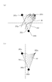
- FIG. 6 is an explanatory diagram of a corner B. (Example 1) It is explanatory drawing of the angle
- FIG. (Example 1) 6 is a graph showing the relationship between the position of a target and angles A to D.
- Example 1) 6 is a graph showing the relationship between the position of a target and a corner B.
- Example 1) 5 is a graph showing the relationship between the position of a target and a corner C.
- E. (Example 1) 4 is a graph showing the relationship between the position of a target and a corner D.
- Example 1 It is a graph which shows the relationship between the position of a target object, and the angle
- (Example 1) It is explanatory drawing of the display of a monitor screen.
- Example 1 It is explanatory drawing of angle Au and angle Cu .
- Example 2) It is explanatory drawing of angle Bu .
- Example 2) It is explanatory drawing of angle
- Example 2 It is explanatory drawing of (a) operation
- Example 2 It is explanatory drawing of (a) operation
- Example 2) 6 is a graph showing the relationship between the position of a target and angles A u to D u .
- Example 2) 6 is a graph showing the relationship between the position of a target and angles A u to D u .
- Example 2 6 is a graph showing the relationship between the position of a target and angles A u to D u .
- Example 2 It is explanatory drawing which shows the attitude
- Example 3 It is explanatory drawing which shows the attitude
- Example 3) It is explanatory drawing of a control object triangle.
- Example 3) It is explanatory drawing of the display of a monitor screen.
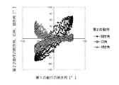
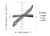
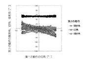
- Example 3) It is a graph which shows the relationship between 1st operation
- Example 3) It is a graph which shows the relationship between 1st operation
- Example 3 It is a graph which shows the relationship between 1st operation
- Example 3 It is explanatory drawing of the display of a monitor screen.
- Example 3) It is explanatory drawing of a coordinate system.
- Example 3) It is explanatory drawing of an opening angle, an elevation angle, and an inclination angle.
- Example 3) It is explanatory drawing of operation
- Example 4 It is explanatory drawing which shows the attitude
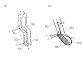
- Example 6 It is explanatory drawing of a coordinate system. (Example 6) It is explanatory drawing of the opening angle of a hand, an elevation angle, and an inclination angle. (Example 6) It is explanatory drawing of a control object triangle. (Example 6) It is explanatory drawing of the display of a monitor screen. (Example 6) It is explanatory drawing of the display of a monitor screen. (Example 6) It is explanatory drawing of the display of a monitor screen. (Example 6) It is explanatory drawing of the display of a monitor screen. (Example 6) It is explanatory drawing of the display of a monitor screen. (Example 6) It is a graph which shows the relationship between 1st operation
- Example 6 It is a graph which shows the relationship between 1st operation
- Example 6 It is explanatory drawing of (a) operation
- Example 7 It is explanatory drawing of (a) operation
- Example 7) It is explanatory drawing of (a) operation
- Example 7 It is explanatory drawing of (a) operation
- Example 7 It is explanatory drawing of (a) operation
- Example 7 It is a graph which shows the actual operation
- Example 1 will be described with reference to FIGS. 1 to 13 and FIG.
- a control command for operating the control target is generated based on the movement of the lower limb.
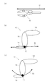
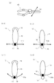
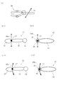
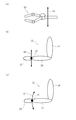
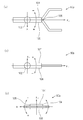
- FIG. 1A, FIG. 2A, and FIG. 3A are explanatory diagrams schematically showing the operation of a control target 80 such as a robot arm.
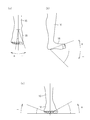
- 1 (b), 2 (b-1), 2 (b-2), and 3 (b) are explanatory diagrams schematically showing a reference operation of the lower limb 12 including the thigh 14 and the lower leg 16.
- Reference numeral 18 denotes a foot.
- 1 (c), 2 (c-1), 2 (c-2), and 3 (c) are explanatory diagrams schematically showing the actual operation of the lower limb 12.
- FIG. 1 (c), 2 (c-1), 2 (c-2), and 3 (c) are explanatory diagrams schematically showing the actual operation of the lower limb 12.
- FIGS. 1 (a) and 1 (b) The movement of the control object 80 and the reference movement of the lower limb 12 are shown in FIGS. 1 (a) and 1 (b), FIG. 2 (a), (b-1) and (b-2), FIG. 3 (a) and (
- the correspondence between the movement of the control object 80 and the movement of the lower limb 12 for operating the control object 80 can be easily understood. Can be operated.
- a control command for linearly moving the control target 80 in the front-rear direction and as shown by an arrow 52 in FIG. Is associated with a reference operation for linearly moving the. 2A, a control command for linearly moving the control target 80 in the left-right direction, as indicated by arrows 94, and as indicated by arrows 54a, 54b in FIGS. 2B-1 and 2B-2.
- a reference operation for linearly moving the ankle 17 which is a reference part in the left-right direction is associated with the reference part.
- a control command for linearly moving the control target 80 in the vertical direction and as shown by an arrow 56 in FIG. Corresponding to the reference movement for linear movement in the direction.
- the ankle 17 may be linearly moved in the left-right direction as indicated by the arrows 54a and 54b.
- the ankle 17 has an arcuate shape centered on the hip joint as viewed from above, along with an arcuate curve movement centered on the knee joint. In order to move the curve, the combined curve movement is performed.
- the ankle 17 is linearly moved in the vertical direction as indicated by the arrow 56 in FIG. 3B, the thigh 14 is actually rotated around the hip joint as indicated by the arrow 57 in FIG.
- the ankle 17 moves along an arc as indicated by an arrow 58 in order to keep the lower leg 16 parallel to the vertical direction.
- a mathematical formula for converting the actual movement of the lower limb into the movement of the lower limb estimated to be executed is prepared (first step).
- the movement of the operator's lower limb is measured (second step).
- the measured motion is converted using the prepared mathematical formula, and a control command is generated based on the converted motion (third step).
- the first action including the reference action that is a reference action associated with the control command and moves the reference part of the body in the reference direction, and the execution of the first action.
- a mathematical expression for associating the second operation which is an actual operation when the operation is performed intentionally, is prepared.
- the movement of the reference portion of the operator is measured.
- the motion measured in the second step is converted using the mathematical formula prepared in the first step, and based on the reference motion component included in the converted motion. To calculate the control command.
- the reference portion is an ankle.
- a common mathematical expression may be prepared for a plurality of operators, or a separate mathematical expression may be prepared individually, that is, for each operator. If a separate mathematical formula is prepared individually, that is, for each operator, a mathematical formula that reflects the movement characteristics of each operator more accurately is used than when a common mathematical formula is prepared for a plurality of operators. Therefore, it is possible to generate a control command that more accurately reflects the intention of each operator.
- the reference direction for operating the reference part of the body is the front-rear direction, the left-right direction, or the vertical direction of the body defined based on the basic posture of the body, the body Since the reference direction can be recognized even when the posture is oblique with respect to the direction of gravity, an operation for control is facilitated, which is preferable.
- the reference direction is a gravity direction or a horizontal direction perpendicular to the gravity direction, the gravity direction and the horizontal direction can be intuitively recognized, so that the operation for control is easy and preferable.
- the movement of the lower limb is a three-dimensional coordinate (X t , Y) of the position of the ankle as a variable expressing the second movement. It is conceivable to use t 1 , Z t ), but if the following angles A to D are used as variables, it is easy to construct a mathematical expression to be associated.
- the movement of the ankle can be determined by measuring the four corners A to D shown in the explanatory diagrams of FIGS.
- Corners A to D are measured by appropriate methods, such as photographing the movement of the lower limb with a marker attached to the lower limb, analyzing the captured image, or attaching a three-dimensional position sensor or the like to the lower limb. do it.
- the ankle which is the reference part, is measured not only by directly measuring the ankle movement, but also by measuring movements of the lower leg, knee joint, thigh, and hip joints that move in conjunction with the ankle, and then the ankle.
- An indirect method for calculating the operation may be used.
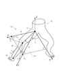
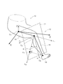
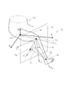
- the x-axis shown in FIGS. 4 to 6 is an axis with the hip joint center O 1 as the origin, parallel to the left-right direction of the body 10 and having the direction from the left side to the right side of the body 10 as the positive direction.
- the y-axis is an axis with the hip joint center O 1 as the origin, parallel to the front-rear direction of the body 10 and having the direction from the rear side to the front side of the body 10 as the positive direction.
- the z-axis is an axis whose origin is the hip joint center O 1, which is parallel to the vertical direction of the body 10 and has a positive direction from the lower side to the upper side of the body 10.
- the x-axis, y-axis, and z-axis are right-handed coordinate systems with the hip joint center O 1 as the origin.
- P 1 be a leg with a perpendicular line dropped from the knee joint center O 2 on the xy plane 71 including the x-axis and the y-axis.
- r-axis a hip joint center O 1 as the origin, the axis passing through P 1, an axis of a direction from the hip joint center O 1 to P 1 as a positive direction.
- z k axis As shown in FIG. 4, z k axis, the knee joint center O 2 as the origin, the axis passing through the hip joint center O 1, the axis being a direction from the hip center O 1 on the knee joint center O 2 as the positive direction is there.
- x k axis, the knee joint center O 2 as an origin, perpendicular to the z k axis is parallel to the axis and the xy plane 71, when viewed in a direction from positive to negative z-axis along the z-axis This is the axis whose clockwise direction is the positive direction.
- x k-axis the direction from the left side of the body 10 to the right positive Direction.
- the y k axis has a direction from the upper side to the lower side of the body 10. Positive direction.
- Corner A has a positive direction in the positive direction and z k axis r-axis is defined by angle.
- Angle A is an angle indicating the rising degree of the thigh 14, to when the knee joint center O 2 is above the xy plane as positive.
- the angle C is defined as an angle formed by the positive direction of the y axis and the positive direction of the r axis.
- the angle C is an angle indicating the degree of opening of the thigh 14 (the degree of opening of the crotch), and the direction in which the thigh 14 opens (the direction to open the crotch, the direction in which the knee joint center O 2 is away from the center of the other knee joint) is positive. To do.
- K P2 axis knee joint center O 2 as an origin at the axis passing through the P 2, an axis of a direction from the knee joint center O 2 to P 2 as a positive direction.
- the angle B is defined as an angle formed by the positive direction of the y k axis and the positive direction of the K P2 axis.
- Angle B is the degree of the rotation of the lower leg 16 by twisting of the femur 14, viewed in a direction toward the direction direction (leg 18 of the inner thigh is away from the other foot, from the positive z k axis along the z k axis negative (Clockwise direction) is positive.
- the x k axis plane 73 parallel to the z axis and wherein the legs of the perpendicular line beat from the ankle center O 3 and P 3.
- Corner D is a positive direction in the positive direction and K P3 axis K O3 axis is defined by angle.
- the angle D is how the lower leg 16 is raised by bending and stretching the knee, and the direction in which the knee is stretched is positive.
- the subject sits on a chair and can move freely with the lower limbs floating in the air.
- the subject takes a posture such that the lower leg is substantially parallel to the vertical direction of the body, and the lower leg is in front of the body, and is substantially parallel to the front-rear direction of the body.
- a target object is arrange
- the subject was conscious of the correspondence shown in FIGS. 1 (a) and (b), FIGS. 2 (a), (b-1) and (b-2), and FIGS. 3 (a) and (b). Move the lower limb as you think it is necessary to realize the movement of the target.
- the angles A to D are measured by analyzing an image taken with the marker attached to the lower limb of the subject.
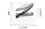
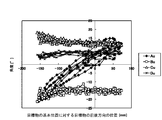
- FIG. 7 corresponds to the linear movement in the left-right direction (x-axis direction) of the target (control target) as shown in FIG. 2 (a), and FIG. 2 (a), (b-1) and (b -2) is a graph showing experimental results when the subject moves the lower limbs in consideration of the correspondence shown in (2). That is, during the experiment, the subject moved the lower limb with the intention of moving the ankle linearly in the left-right direction in the same manner as the linear movement of the target in the left-right direction.
- the horizontal axis indicates the position (x obs ) in the left-right direction of the target with respect to the basic position of the target, and the vertical axis indicates the angles A to D.
- the angle A and the angle D are substantially constant, and the change amount of the angle B and the change amount of the angle C are approximately proportional to the movement amount of the target in the left-right direction (x-axis direction).
- the subject intended to move linearly as shown in FIGS. 2 (b-1) and 2 (b-2), but the actual operation is to open and close the crotch as shown in FIG. 2 (c-2).
- This is a curvilinear motion that combines the arc-like motion caused by the thigh rotation caused by the rotation and the arc-like motion caused by the rotation of the lower leg caused by the thigh twist as shown in FIG. 2 (c-1). .
- f B (B) is a function of angle B
- f C (C) is a function of angle C
- f BC (B, C) is a function of angle B and angle C.
- x ob f B (B) (1)
- x ob f C (C) (2)
- x ob f BC (B, C) (3)
- FIGS. 3A and 3B are conscious of the linear movement in the vertical direction (z-axis direction) of the target (control target) as shown in FIG. Then, the angles A to D when the subject moved the lower limbs were measured. That is, during the experiment, the subject moved the lower limb with the intention of moving the ankle linearly in the vertical direction, similar to the linear movement of the target in the vertical direction.
- the angle B, the angle C, and the angle D are substantially constant, and the change amount of the angle A is substantially proportional to the amount of movement of the target in the vertical direction (z-axis direction). That is, the subject intended to move linearly as shown in FIG. 3B, but the actual action is a curved action as shown in FIG. 3C. From this, the angle (A, B, C, D) that measured the movement of the lower limb and the position (z obs ) of the target with respect to the basic position of the target in the z-axis direction are expressed by , Can be associated.
- f A (A) means a function of the angle A.
- z ob f A (A) (5)
- the functions of the equations (1) to (5) can be determined by various methods such as using an approximate straight line or an approximate curve obtained by applying the least square method to data obtained by measuring the movement of the lower limbs. It is. Further, the amount of change in x ob with respect to the amount of change in angular B obtained from the approximate line and a proportional constant, function or in which the x ob and angular B becomes proportional, x ob with respect to the amount of change in angular C obtained from the approximate line of the variation as a proportionality constant, function or in which the x ob and angular C becomes proportional, the amount of change in y ob with respect to the amount of change in the angular D obtained from the approximate line is the proportional constant, and the y ob and the corner D
- a function having a proportional relationship or a change amount of z ob with respect to a change amount of angle A obtained from an approximate straight line is set as a proportional constant, and a function having
- the expressions (1) to (5) can be expressed as the following expressions (1 ′) to (5 ′).
- x ob bB (1 ′)
- x ob cC (2 ′)
- y ob dD (4 ′)
- z ob aA (5 ')
- a, b, b ′, c, c ′, d, and e are constants.
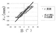
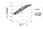
- FIG. 8 is a graph showing the relationship between the corner B and the position x ob in the left-right direction of the target, and shows an example of the actual measurement value of the corner B and a straight line obtained from the equation (1 ′).
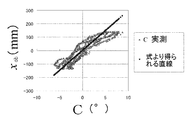
- FIG. 9 is a graph showing the relationship between the corner C and the position x ob in the left-right direction of the target, and shows an example of the actual measurement value of the corner C and a straight line obtained from the equation (2 ′).
- FIG. 10 is a graph showing the relationship between E and the position x ob in the left-right direction of the target. An example of (value) and a straight line obtained from the equation (3 ′) are shown.
- FIG. 11 is a graph showing the relationship between the corner D and the position yob in the front-rear direction of the target, and shows an example of the measured value of the corner D and a straight line obtained from the equation (4 ′).
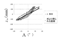
- FIG. 12 is a graph showing the relationship between the corner A and the position z ob in the vertical direction of the target, and shows an example of the actual measurement value of the corner A and a straight line obtained from the equation (5 ′).
- Equations (1 ′) to (5 ′) show the relationship between the position of the target (left side) with respect to the basic position of the target and the angles A to D, which are variables representing the position of the ankle with respect to the basic position of the ankle.
- the subject is moving with the intention that the position of the ankle with respect to the basic position of the ankle is the same as the position of the target with respect to the basic position of the target.
- the left side of the equations (1 ′) to (5 ′) means the position of the ankle intended by the subject (the position of the ankle with respect to the basic position of the ankle). That is, the left side of the equations (1 ′) to (5 ′) corresponds to the first operation, and the right side corresponds to the second operation.
- the expressions (3 ′) to (5 ′) include the reference motion prepared in the first step, which is the reference motion associated with the control command and moves the body reference region in the reference direction. This is a mathematical expression that associates the first operation with the second operation that is the actual operation when the operation is intended to be executed.
- the expression (3 ′) ⁇ x ob, y ob, z ob (5 ') is a reference action associated with "control command first operation including the reference operation for operating the reference part of the body (the ankles) in the reference direction
- control command first operation including the reference operation for operating the reference part of the body (the ankles) in the reference direction
- Represents the position of the reference portion in FIG. A, B, C, and D in the expressions (3 ′) to (5 ′) are parameters representing the second operation that is an actual operation when the operation is intended to execute the first operation.
- the mathematical formula prepared in the first step is simplified, but other parameters may be used.
- a relational expression between the target position xob , yob , zob and parameters other than the angles A, B, C, D may be obtained using regression analysis (single regression analysis or multiple regression analysis).
- the first operation may include a composite operation such as an oblique direction.
- the ankle movements in the first and second movements are both defined by variables (the same plural variables) representing the positions of the ankle in the front-rear, left-right, and vertical directions.
- variables the same plural variables representing the positions of the ankle in the front-rear, left-right, and vertical directions.
- FIG. 1B for the first operation in which only the variable indicating the position of the ankle in the front-rear direction is changed, as shown in FIG. Since the second motion in which two variables of the variable representing the position of the ankle and the variable representing the position of the ankle in the up-and-down direction correspond to each other, these may be used as a formula for associating them.
- the mathematical expression that associates the first movement and the second movement is one of the variables.
- the first motion including the motion element of the reference portion that only changes is associated with the second motion including motion components in which a plurality of variables among these variables changes corresponding to the motion element. Even in the case of the first operation in which only the variable representing the horizontal position of the ankle in FIG. 2 is changed, or in the case of the first operation in which only the variable representing the vertical position of the ankle in FIG. is there.
- the mathematical expression that associates the first motion and the second motion is “the component of the second motion corresponding to the linear motion component of the first motion in which the ankle linearly moves in the longitudinal direction of the body is It may be a mathematical expression that incorporates the fact that when viewed in a direction parallel to the central axis of rotation of the bending and stretching movement, the curved movement of the ankle is bent so that the knee joint side is inward.
- the curved inner side (concave side) of the curved movement of the ankle is a curved movement bent so as to face the knee joint or the vicinity thereof. Is taken into the formula.
- the mathematical expression for associating the first motion and the second motion is “the component of the second motion corresponding to the linear motion component of the first motion in which the ankle linearly moves in the front-rear direction of the body is a curved curve at the ankle.
- a curved motion component that moves, and the curve of the curved motion component is a convex or concave curve when viewed in a direction parallel to the central axis of rotation of the knee joint bending and stretching motion, and is a straight line that passes through both ends of the curve.
- a convex or concave curve 800 is shown in the explanatory diagram of FIG.
- the region is divided into two by a straight line 806 passing through points 802 and 804 at both ends of the curve 800.
- the curve 800 does not exist in one region 820 of the regions 810 and 820 divided by the straight line 806.
- “A region surrounded by a curve and a straight line (a straight line passing through both ends of the curve)” corresponds to a region surrounded by the curve 800 and the straight line 806 in FIG.
- “On a straight line (a straight line passing through both ends of the curve)” corresponds to a straight line 806 in FIG.
- the “convex or concave curve” may be a convex or concave curve as a whole.
- the curve when looking at the shape of the curve in detail, even if the curve includes a high-frequency waveform (a waveform with a shorter wavelength than the overall curve length), the curve is viewed macroscopically, If the overall shape can be regarded as convex or concave, the curve may be treated as a “convex or concave curve”. Further, the “straight line passing through both ends of the curve” may be a straight line passing through both ends of the convex or concave curve corresponding to the overall shape of the curve.
- the expression (4 ′) is an expression that takes in that the second motion component is an arcuate curved motion along one arc centered on the knee joint when viewed from a predetermined direction.
- the mathematical formula that associates the first motion with the second motion is “the component of the second motion corresponding to the linear motion component of the first motion in which the ankle linearly moves in the left-right direction of the body is applied to the knee joint.
- the first curved motion of the ankle bent so that the knee joint side is inward, and the hip joint side is viewed from above the body.
- It may be a mathematical expression that incorporates “being a curved motion including at least one of the second curved motions of the ankle bent so as to be inside”.
- the curved inner side (concave side) of the first curved motion faces the knee joint or the vicinity thereof.
- the curved inner side (concave side) of the second curved motion faces the hip joint or the vicinity thereof.
- the mathematical expression for associating the first motion and the second motion is “the component of the second motion corresponding to the linear motion component of the first motion in which the ankle linearly moves in the left-right direction of the body is a curve at the ankle. It is a curved motion component that moves, and the second motion component is: (a) the curve of the curved motion component is convex when viewed in a direction parallel to the axis connecting the hip joint of the lower limb including the knee joint and the knee joint.
- a concave curve one of the two regions divided by a straight line passing through both ends of the curve, a region where no curve exists, a region surrounded by a curve and a straight line (straight line passing through both ends of the curve), and a straight line (curve A straight curve passing through both ends of the ankle) and at least one of the first curved motion of the ankle with the knee joint, and (b) a curve of the curved motion component is convex or concave when viewed from above the body. This is a curve that is bisected by a straight line that passes through both ends of the curve.
- An ankle that has a hip joint in at least one of one area where no curve exists, an area surrounded by a curve and a straight line (straight line passing through both ends of the curve), and a straight line (a straight line passing through both ends of the curve) It is good also as a numerical formula which took in that it will become a curve movement including at least one among the 2nd curve movements.
- Expressions (1 ′), (2 ′), and (3 ′) are arcuate curves along an arc whose center is at least one of the knee joint and the hip joint when the second motion component is viewed from a predetermined direction. It is a mathematical formula that captures that it is a motion, but a mathematical formula that captures the fact that an arc-shaped curved motion along another arc whose center position and radius are different from those arcs is a component of the second motion, It may also be a mathematical expression that takes into account that the motion component of 2 is a substantially arc-shaped curved motion.
- the mathematical formula that associates the first motion with the second motion is “the component of the second motion corresponding to the linear motion component of the first motion in which the ankle linearly moves in the vertical direction of the body is the vertical motion of the body.
- the mathematical formula that associates the first motion with the second motion is “the component of the second motion corresponding to the linear motion component of the first motion in which the ankle linearly moves in the vertical direction of the body.
- it corresponds to the vertical component of the line segment connecting the knee joint and the ankle
- the curved inner side of the curved motion of the ankle taken into the formula
- the (concave side) faces a position that is a predetermined distance from the hip joint (a distance corresponding to the vertical component of the line segment connecting the knee joint and the ankle) or its vicinity.
- the expression (5 ′) is an expression that takes in that the second motion component is an arcuate curved motion along one arc when viewed from a predetermined direction.
- the mathematical expression for associating the first motion and the second motion is “the second motion component corresponding to the linear motion component of the first motion in which the ankle linearly moves in the vertical direction of the body is curved at the ankle.
- a curved motion component that moves, and the curve of the curved motion component is a plane parallel to the vertical direction of the body, and is viewed in a direction perpendicular to the plane including the hip joint and knee joint of the lower limb including the knee joint
- a convex or concave curve one of the regions divided by a straight line passing through both ends of the curve, and a region surrounded by a curve and a straight line (a straight line passing through both ends of the curve), "At least one of the straight lines (straight lines that pass through both ends of the curve) has a position that is lowered from the hip joint by a distance corresponding to the vertical component of the line connecting the knee joint and ankle.” It may be a mathematical formula.
- the mathematical expression for associating a first motion including a motion component in which the reference portion performs a linear motion with a second motion corresponding to the first motion is such that the component of the second motion corresponding to the motion component is: It is a mathematical formula that incorporates the curve motion of the reference portion.
- Experiment 2 will be described as a specific example of the second and third steps.
- the position of the control target displayed on the monitor screen is controlled based on the movement of the lower limbs.
- the measurement of the movement of the lower limb is performed in the same manner as in the first step.
- the lower limbs are operated with reference to a posture in which the lower leg is substantially parallel to the vertical direction of the body and the lower leg is substantially parallel to the longitudinal direction of the body.
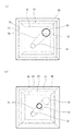
- FIG. 13 is an explanatory diagram of display on the monitor screen.
- a frame 39 indicating the depth
- a circle 30 indicating the initial position of the controlled object whose position is controlled by the lower limbs
- a corresponding rectangular broken line 31 indicating the initial position of the controlled object whose position is controlled by the lower limbs
- a circle 32 indicating the target position and the corresponding circle
- a rectangular broken line 33 indicating the current position
- a corresponding rectangular broken line 41 is displayed, and an ideal movement path from the initial position to the target position is displayed by a pair of line segments 34.
- the program used in Experiment 2 measures the lower limb movements, that is, the angles A to D in the same manner as in Experiment 1, converts them using Equations (3 ′) to (5 ′), and converts the intended ankle of the subject.
- the position ( xob , yob , zob ) is calculated, and the display of the circle 40 of the current position displayed on the monitor screen, that is, the position and size, is changed corresponding to the position.
- the test subject displays a screen display during movement as shown in FIG. 13 (b) from the state where the circle 40 indicating the current position is displayed in the vicinity of the circle 30 at the initial position.
- the lower limb is moved so that the circle 40 indicating the current position passes through the center between the pair of line segments 34 while touching the two straight lines of the pair of line segments 34, and near the circle 32 of the target position, A circle 40 indicating the current position is displayed.
- a circle 40 indicating the current position is displayed in the vicinity of the target position circle 32 for a certain period of time
- a circle 32 indicating the target position appears at a new position
- the previous target position circle 32 is To a circle 30 representing the initial position.
- the target position appears 7 times.
- the seven target positions were set so as not to be biased.
- the value calculated based on the time average of the lengths of the perpendiculars drawn to the straight line connecting the center points of the circle 30 at the initial position and the circle 32 at the target position is measured.
- b ′ in equation (3 ′) is 7.64
- c ′ is 9.37
- d in equation (4 ′) is 7.51
- a in equation (5 ′) is 7.88.
- Table 1 below shows the experimental results.
- the “required time” in Table 1 is an average value of the movement time until the current position circle reaches the seventh target position.
- “Accuracy” in Table 1 is an average value of the average positional deviation amount during movement until the circle at the current position reaches the seventh target position. The smaller the value, the more ideal the movement path. , Means moved more accurately. From Table 1, it can be seen that the time required for the equations (3 ′) to (5 ′) is shortened and the moving route is also accurate.
- Example 2 will be described with reference to FIGS.
- a control command for operating the control target is generated based on the movement of the upper limb.
- the movement of the upper limb is a three-dimensional coordinate (X s , Y) of the wrist position as a variable expressing the second movement.
- X s , Y three-dimensional coordinate
- s 1 , Z s can be used, but if the following angles A u to D u are used as variables, it is easy to construct a mathematical expression to be associated.
- the movement of the wrist can be determined by measuring the four angles A u to D u shown in the explanatory diagrams of FIGS.
- the angles A u to D u are obtained by photographing the movement of the upper limb 22 with a marker attached to the upper limb 22, analyzing the photographed image, attaching a three-dimensional position sensor or the like to the upper limb 22, etc. What is necessary is just to measure by an appropriate method.
- the wrist measurement which is the reference part, measures not only the method of directly measuring wrist movement, but also the movements of the forearm, elbow joint, upper arm, and shoulder joints that move in conjunction with the wrist. An indirect method for calculating wrist movement may be used.
- the x u axis shown in FIGS. 14 to 16 is an axis having the shoulder joint center O 1u as the origin, parallel to the horizontal direction of the body 10 and having the direction from the left side to the right side of the body 10 as the positive direction.
- the yu axis is an axis whose origin is the shoulder joint center O 1u , parallel to the front-rear direction of the body 10, and having a positive direction from the rear side to the front side of the body 10.
- the z u- axis is an axis having the shoulder joint center O 1u as the origin, parallel to the vertical direction of the body 10 and having the direction from the lower side to the upper side of the body 10 as the positive direction.
- the x u axis, the yu axis, and the z u axis are right-handed coordinate systems with the shoulder joint center O 1u as the origin.
- r u axis is an origin shoulder joint center O 1u, an axis passing through the P 1u, an axis being a direction from the shoulder joint center O 1u to P 1u as a positive direction.
- the z ku axis is an axis passing through the shoulder joint center O 1u with the elbow joint center O 2u as the origin, and the direction from the shoulder joint center O 1u toward the elbow joint center O 2u is defined as the positive direction.
- x ku axis, the elbow joint center O 2u an origin, perpendicular to the z ku axis is x u z u plane 74 parallel to the axis is a plane containing the x u-axis and z u-axis, y u axis it is an axis clockwise direction is the positive direction when viewed in a direction from the positive y u-axis negative along.
- the x ku axis is a direction from the left side to the right side of the body 10. Is the positive direction.
- the y ku axis has an elbow joint center O 2u as the origin, is an axis perpendicular to the x ku axis and perpendicular to the z ku axis, and a positive direction is defined so as to form a right hand coordinate system together with the x ku axis and the z ku axis This is the axis.
- the y ku axis is directed from the front side to the rear side of the body 10.
- the direction is the positive direction.
- Angle A u is a positive direction in the positive direction and z ku axis r u axis is defined by angle.
- the angle A u is an angle indicating how the upper arm 24 is raised in the front-rear direction, and is positive when the elbow joint center O 2u is in front of the x u z u plane.
- the angle C u is defined as an angle formed by the negative direction of the z u axis and the positive direction of the ru axis.
- the angle Cu is an angle indicating the degree of side opening (the degree of the upper arm 24 rising in the left-right direction), and the direction in which the side opens is positive.
- K P2u axis as an origin elbow joint center O 2u, the axis passing through the P 2u, is an axis of a direction from elbow center O 2u the P 2u positive direction.
- the angle B u is defined as an angle formed by the negative direction of the y ku axis and the positive direction of the K P2u axis.
- Angle B u is the degree of rotation of the forearm 26 about the z ku axis, clockwise when the hand 28 is viewed in the direction of negative to positive of the z ku axis along the direction (z ku axis away from the other hand The direction of rotation is positive.
- Corner D u is a positive direction in the positive direction and K P3u axis K O3u axis is defined by angle.
- the angle Du is the degree of bending of the elbow 25, and the direction in which the elbow 25 is bent is positive.
- the subject takes a posture in which the upper arm of the upper limb is substantially parallel to the vertical direction of the body, the forearm of the upper limb is on the front side of the body, and is substantially parallel to the front-rear direction of the body. And a target object is arrange
- Subject is aware of the correspondence shown in FIGS. 17 (a), (b-1) and (b-2), FIGS. 18 (a) and (b), FIGS. 19 (a) and (b), Move the upper limb as you think it is necessary to achieve the movement of the target.
- the angles A u to D u are measured by analyzing an image taken with a marker attached to the upper limb of the subject.
- FIG. 20 corresponds to the linear movement of the target (control target) in the left-right direction ( xu- axis direction) as shown by the arrow 94 in FIG. 17A, and FIGS. It is a graph which shows the experimental result when a test subject moves an upper limb in consideration of the correspondence shown in 1) and (b-2). That is, during the experiment, the subject moved the upper limb with the intention of moving the wrist 27 linearly in the left-right direction in the same manner as the linear movement of the target in the left-right direction.
- the horizontal axis indicates the position of the target in the left-right direction relative to the basic position of the target, and the vertical axis indicates the angles A u to D u .
- the angle A u and the angle D u are substantially constant, and the amount of change of the angle B u and the amount of change of the angle C u are substantially proportional to the amount of movement of the target in the left-right direction (x u- axis direction).
- f Bu (B u ) means a function of the angle B u
- f Cu (C u ) means a function of the angle C u
- f BCu (B u , C u ) means a function of the angle B u and the angle C u .
- x obu f Bu (B u ) (6)
- x obu f Cu (C u ) (7)
- x obu f BCu (B u , C u ) (8)
- FIG. 21 corresponds to the linear movement of the target (control target) in the front-rear direction ( yu axis direction) as indicated by an arrow 97 in FIG. 5 is a graph showing the experimental results when the subject moves the upper limb in consideration of the association indicated by arrows 97 and 68 in FIG. That is, during the experiment, the subject moved the upper limb with the intention of moving the wrist linearly in the front-rear direction, similar to the linear movement of the target in the front-rear direction.
- the horizontal axis indicates the position of the target in the front-rear direction with respect to the basic position of the target, and the vertical axis indicates the angles A u to D u .
- the angle B u , the angle C u and the angle D u are substantially constant, and the amount of change of the angle A u may be approximately proportional to the amount of movement of the target in the front-rear direction (the yu axis direction).
- the subject rotates the upper arm 24 as shown by an arrow 69 in FIG. Therefore, angle operation was measured upper limb (A u, B u, C u, D u) and, y u-axis direction position of the object relative to the basic position of the target and (y obu) are the following Correspondence can be made by equation (9).
- f Au (A u ) means a function of the angle A u .
- y obu f Au (A u ) (9)
- FIG. 22 corresponds to the linear movement in the vertical direction (z u- axis direction) of the target (control target) as shown by the arrow 96 in FIG. It is a graph which shows an experimental result when a test subject moves an upper limb in consideration of the association shown in FIG. That is, during the experiment, the subject moved the upper limb with the intention of moving the wrist linearly in the vertical direction, similar to the linear movement of the target in the vertical direction.
- the horizontal axis indicates the vertical position of the target relative to the basic position of the target, and the vertical axis indicates the angles A u to D u .
- the angle A u , the angle B u, and the angle C u are substantially constant, and the amount of change in the angle D u may be approximately proportional to the amount of movement of the target in the vertical direction (z u- axis direction).
- the subject intended to move linearly as indicated by an arrow 66 in FIG. 18B, but the actual movement is due to bending and stretching of the elbow joint as indicated by an arrow 67 in FIG. It is an arcuate curved action.
- the functions of the equations (6) to (10) can be determined by various methods such as using an approximate line or an approximate curve obtained by applying the least square method to data obtained by measuring the motion of the upper limb. It is. Further, the amount of change in x obu with respect to the amount of change in angular B u obtained from the approximate line and a proportional constant, x obu and or function and the corner B u is proportional, the amount of change in angular C u obtained from the approximate line the variation of x obu a proportionality constant, function or in which the x obu and angular C u becomes proportional to the amount of change in y obu with respect to the amount of change in angular a u obtained from the approximate line a proportional constant for, y obu And a function in which the angle A u is proportional to each other, or a function in which the amount of change in z obu relative to the amount of change in the angle D u obtained from the approximate line is a proportion
- Expressions (6) to (10) can be expressed as the following Expressions (6 ′) to (10 ′).
- x obu bu u u (6 ')
- x obu c u C u (7 ')
- y obu a u A u (9 ')
- z obu d u D u (10 ')
- a u , b u , b u ′, c u , c u ′, d u and eu are constants.
- Expressions (6 ′) to (10 ′) represent the relationship between the position (left side) of the target with respect to the basic position of the target and the angles A u to D u that are variables representing the position of the wrist with respect to the basic position of the wrist. Show. The subject is moving with the intention that the position of the wrist relative to the basic position of the wrist is the same as the position of the target relative to the basic position of the target. Therefore, the left side of the equations (6 ′) to (10 ′) means the wrist position intended by the subject (the wrist position with respect to the wrist basic position). That is, the left side of the equations (6 ′) to (10 ′) corresponds to the first operation, and the right side corresponds to the second operation.
- Expression (8 ′) For example, assume that the movement amount in the xu- axis direction is associated by Expression (8 ′), and Expression (6 ′) and Expression (7 ′) are not used. That is, consider the case of using equations (8 ′) to (10 ′). In this case, the expressions (8 ′) to (10 ′) are prepared in the first step, and include the “reference operation associated with the control command, which moves the reference region of the body in the reference direction. This is a mathematical expression that associates the first operation with the second operation that is the actual operation when the operation is intended to be executed.
- equation (8 ') X obs , y obs , and z obs of (10 ′) are “a first motion including a reference motion associated with a control command and moving a reference region (wrist) of the body in a reference direction. Represents the position of the reference portion in FIG. A u , B u , C u , and D u in Expressions (8 ′) to (10 ′) are parameters representing a second operation that is an actual operation when the operation is intended to execute the first operation. It is.
- the first operation may include a composite operation such as an oblique direction.
- the mathematical expression that associates the first movement and the second movement is one of the variables.
- the first motion including the motion element of the reference portion that only changes is associated with the second motion including motion components in which a plurality of variables among these variables changes corresponding to the motion element. The same applies to the first operation in FIG. 18 in which only the variable representing the vertical position of the wrist changes.
- the mathematical expression for associating the first motion with the second motion is “the component of the second motion corresponding to the linear motion component of the first motion in which the wrist linearly moves in the vertical direction of the body is the elbow joint. It may be a mathematical expression that incorporates “curvature movement of the wrist bent so that the elbow joint side is inward when viewed in a direction parallel to the rotation center axis of the bending and stretching movement”. In this case, “curve motion that is curved so that the curved inner side (concave side) of the wrist curl motion faces the elbow joint or its vicinity when viewed in a direction parallel to the center axis of rotation of the elbow joint. “To be” is taken into the formula.
- the mathematical expression for associating the first motion and the second motion is “the second motion component corresponding to the linear motion component of the first motion in which the wrist linearly moves in the vertical direction of the body is curved on the wrist.
- a curved motion component that moves, and the curve of the curved motion component is a convex or concave curve when viewed in a direction parallel to the rotation center axis of the bending and stretching motion of the elbow joint, and is a straight line passing through both ends of the curve.
- the expression (10 ′) is an expression that takes in that the second motion component is an arcuate curved motion along one arc centered on the elbow joint when viewed from a predetermined direction.
- a formula that incorporates the fact that an arc-shaped curved motion along another arc whose center position and radius are different from one arc is a component of the second motion, and that the component of the second motion is a substantially arc-shaped It may be a mathematical formula that incorporates a curved motion.
- the mathematical expression that associates the first motion with the second motion is “the second motion component corresponding to the linear motion component of the first motion in which the wrist linearly moves in the horizontal direction of the body is the elbow joint.
- the first curved movement of the wrist bent so that the elbow joint side is inward when viewed in a direction parallel to the axis connecting the shoulder joint of the upper limb and the elbow joint, and the shoulder joint when viewed from the front of the body It is also possible to use a mathematical expression that incorporates “being a curved motion including at least one of the second curved motions of the wrist bent so that the side is inward”.
- the curved inner side (concave side) of the first curved motion faces the elbow joint or the vicinity thereof.
- the curved inner side (concave side) of the second curved motion faces the shoulder joint or the vicinity thereof.
- the mathematical expression for associating the first motion with the second motion is: “The wrist motion curve corresponding to the linear motion component of the first motion in which the wrist linearly moves in the horizontal direction of the body is curved on the wrist. It is a curved motion component that moves, and the second motion component is (a) when the curve of the curved motion component is viewed in a direction parallel to the axis connecting the shoulder joint of the upper limb including the elbow joint and the elbow joint, A convex or concave curve that is bisected by a straight line passing through both ends of the curve, one of the areas where no curve exists, a region surrounded by a curve and a straight line (a straight line passing through both ends of the curve), and a straight line ( The first curved movement of the wrist with the elbow joint on at least one of the straight line passing through both ends of the curved line) and (b) the curve of the curved movement component is convex or An area that is a concave curve and is bisected by a straight line that passes through both ends
- equations (6 ′), (7 ′), and (8 ′) are arc-shaped along the arc centered on at least one of the elbow joint and the shoulder joint when the second motion component is viewed from a predetermined direction.
- it is a mathematical formula that incorporates a curved motion
- a mathematical formula that incorporates the fact that an arc-shaped curved motion along another arc whose center position and radius are different from those arcs is a component of the second motion It may be a mathematical formula that takes into account that the second motion component is a substantially arc-shaped curved motion.
- the wrist movement of the operator is measured.
- the operator may take a posture in which the upper arm of the upper limb is substantially parallel to the vertical direction of the body, and the forearm of the upper limb is on the front side of the body and is substantially parallel to the front-rear direction of the body.
- the operation measured in the second step is used as the second operation, and the operation measured in the second step is converted into the first operation using the mathematical formula prepared in the first step.
- a control command is calculated based on the reference motion component included in the converted first motion.
- a common mathematical formula may be prepared for a plurality of operators, or a separate mathematical formula may be prepared for each operator. If a separate mathematical formula is prepared for each operator, it is possible to use a mathematical formula that more accurately reflects the motion characteristics of each operator's body than when preparing a common mathematical formula for multiple operators. Thus, it is possible to generate a control command that more accurately reflects the intention of each operator.
- Example 3 will be described with reference to FIGS.
- a control command is generated on the basis of a foot posture changing operation (an operation for changing the posture).
- FIG. 23 is an explanatory diagram schematically showing the posture changing operation of the control target 80p such as a robot hand.
- FIG. 24 is an explanatory diagram schematically showing the posture changing operation of the foot 18.
- FIG. 23 (a) is associated with FIG. 24 (a)
- FIG. 23 (b) is associated with FIG. 24 (b)
- FIG. 23 (c) is associated with FIG.
- the correspondence relationship between the posture changing motion of 80p and the posture changing motion of the foot 18 can be easily understood.
- the opening angle ⁇ h that is the rolling angle is associated.
- the a control object 80p angle to rotate about the x r axis theta as shown by the arrows in FIG. 24 (b)
- the dorsiflexion of the foot 18 (extension) or correlating the elevation theta g is the angle of plantarflexion (bending).
- 31 (a) and 31 (b) show a hip joint central coordinate system X 1 -Y 1 -Z 1 (hereinafter referred to as sigmaO) and a lower limb coordinate system x 1 -y 1 -z 1 (hereinafter referred to as the right leg). , SigmaL.), An explanatory diagram of the foot coordinate system x 1 '-y 1 ' -z 1 '(hereinafter referred to as sigmaF).
- sigmaO, sigmaL, and sigmaF are orthogonal coordinate systems.
- the origin O of sigmaO is set as the center of the right hip joint in a basic posture in which the back muscles are stretched and the hip joint and knee joint are bent 90 degrees each.
- X 1 axis sigmaO is parallel to the straight line passing through the left and right hip center of the body, right direction of the body is a positive direction.
- Z 1 axis is parallel to the vertical direction of the body, upward is the positive direction.
- the Y 1 axis is orthogonal to the X 1 axis and the Z 1 axis, and the front of the body is the positive direction.
- x 1 axis is parallel to the rotation axis of the right knee joint, the direction from the inside of the right lower leg outside a positive direction.
- the z 1 axis coincides with the long leg lower axis of the right leg (axis passing through the ankle center and the knee joint center), and the direction from the ankle center to the knee joint center is the positive direction.
- y 1 axis is orthogonal to the x 1 axis and z 1 axis, the positive direction is defined as x 1 axis, with z 1 axis constituting a right-handed coordinate system.
- the origin is the right ankle center P.
- the x 1 ′ axis is parallel to a straight line that crosses the right foot from side to side (a straight line connecting the inside and the outside of the right foot), and the direction from the inside to the outside of the right foot is the positive direction.
- the y 1 ′ axis is parallel to a straight line passing through the second finger and the heel of the right foot and penetrating the right foot in the front-rear direction, and the direction from the heel side to the toe side is the positive direction.
- the z 1 ′ axis is perpendicular to the sole of the foot (perpendicular to the x 1 ′ axis and the y 1 ′ axis), and the direction from the sole to the back of the foot is the positive direction.
- the plantar surface is parallel to the x 1 'y 1 ' plane 195 including the x 1 'axis and the y 1 ' axis.
- the opening angle, the elevation angle, and the inclination angle are relative angles ⁇ h , ⁇ g , and ⁇ k between sigma L and sigma F when sigma F is rotated with respect to sigma L according to the following procedures (1) to (3). .
- Step (1) First, as shown in FIG. 32 (a), 'match with the axis, y 1 axis and y 1' sigmaL and sigmaF and match state (x 1 axis and x 1 and the shaft coincide , Z 1 axis and z 1 'axis coincide with each other), and sigmaF rotated about the z 1 axis by an angle - ⁇ h to obtain the x 1 ''-y 1 ''-z 1 ''coordinates System (hereinafter referred to as sigma F ′).
- sigma F ′ the x 1 ''-y 1 ''-z 1 ''coordinates System
- Step (2) Next, as shown in FIG. 32 (b), sigma F ′ rotated about the x 1 ′′ axis by an angle ⁇ g is converted into x 1 ′ ′′ ⁇ y 1 ′ ′′ ⁇ z 1 Let '''be a coordinate system (hereinafter referred to as sigma F'').
- Step (3) Next, as shown in FIG. 32 (c), the sigma F ′′ rotated about the y 1 ′ ′′ axis by an angle ⁇ k is converted to x 1 ′′ ′′ ⁇ y 1 ′ ′′. It is assumed that “ ⁇ z 1 ′′” is a coordinate system (hereinafter referred to as sigma F ′ ′′).
- the posture of sigma F ′ ′′ viewed from sigma L can be expressed by a set of three angles ( ⁇ h , ⁇ g , ⁇ k ).
- ⁇ h is an opening angle
- ⁇ g is an elevation angle
- ⁇ k is an inclination angle.
- sigmaF ′ ′′ means sigmaF in a state where an opening angle, an elevation angle, and an inclination angle exist.
- the attitude of sigma F ′ ′′ viewed from sigma L means the attitude of sigma F viewed from sigma L.
- FIG. 23A is associated with FIG. 24A
- FIG. 23B is associated with FIG. 24B
- FIG. 23C is associated with FIG. 24C.
- the controlled object 80p is based on the motion of the foot. It is possible to control the posture change operation of the.
- a formula for converting an actual foot posture changing motion into a foot posture changing motion presumed to be executed is prepared (first step), and an operator foot posture changing motion is prepared. Is measured (second step), the measured posture change motion is converted using the prepared mathematical formula, and a control command is generated based on the converted posture change motion (third step).
- Example 3 a foot is used as a reference part.
- the control command is generated so that the opening angle ⁇ h and the angle ⁇ are in a proportional relationship.
- the second reference operation for changing only the elevation angle theta g legs as shown in FIG. 24 (b) a control command for changing only the angle theta of the controlled object 80p which shown in FIG. 23 (b) Associate.
- the origin is at the center of the right ankle
- y 1 axis direction of the z 1 axis is orthogonal coordinate system fixed to the lower leg side has origin knee joint to the knee joint center It is defined by the directions of three axes (the rotation axis of the knee joint, the long leg leg, and the axis orthogonal to those axes).
- the rotation direction corresponding to the opening angle, the elevation angle, and the inclination angle is the reference direction, and as described above, these are the rotation directions defined by sigmaL.
- the reference direction is a coordinate system that is integrally fixed to the lower leg side of the knee joint, which is a part different from the foot that is the reference part (another virtual direction that moves together with the lower leg side of the knee joint).
- the rotation direction is defined by sigma L, which is a coordinate system fixed at a certain position.
- Formulas for converting an actual foot posture changing action into a foot posture changing action presumed to be executed are prepared as follows.
- controlled object triangle 82 the posture of the controlled object is represented by a triangle 82 (hereinafter referred to as “controlled object triangle 82”).
- the control target triangle 82 is displayed on the monitor screen.
- FIG. 25B shows a state in which the vertex 82a and the vertex 82b of the control target triangle 82 are in front of the vertex 82q.
- An axis from the apex 82a to the apex 82b of the control target triangle 82 passes through the root portion 102 of the control target 80p in FIG. 23 and corresponds to an axis that is in the same direction and parallel to the direction from the left side 104 to the right side 105.
- the axis from the middle point 82p of the base 82c connecting the vertex 82a and the vertex 82b of the controlled object triangle 82 to the vertex 82q passes through the root part 102 of the controlled object 80p in FIG. Corresponds to an axis in the same direction and parallel.
- the axis that passes through the root portion 102 of the control target 80p in FIG. 23 corresponds to an axis that is in the same direction as the direction from the lower surface 108 toward the upper surface 107 and is parallel.
- the control target triangle 82 displayed on the monitor screen is operated with the foot 18.
- the posture of the control target triangle 82 displayed on the monitor screen is changed, and the posture of the foot is changed correspondingly.
- the subject is conscious of the association shown in FIGS. 23 (a) and 24 (a), FIG. 23 (b) and FIG. 24 (b), FIG. 23 (c) and FIG. 24 (c).
- the foot posture is changed as necessary to realize the posture change of the control target triangle 82. That is, as shown in the explanatory diagram of FIG. 25 (a), the posture of the foot is changed in consideration of the situation in which the posture of the control target triangle and the posture of the sole of the foot coincide.
- the motion of the control target triangle 82 displayed on the monitor means the motion of the foot intended by the subject.
- the actual motion of the foot (that is, the second motion) at this time is measured in association with the motion of the control target triangle 82 displayed on the monitor (that is, the first motion).
- the actual movement of the foot may be measured by photographing the movement of the foot with a marker attached to the foot, analyzing the captured image, or measuring by an appropriate method.
- the first operation displayed on the monitor includes a plurality of reference operations even if only one of the first to third reference operations is included as shown in FIGS. It may be a composite operation.
- FIG. 26 (a) is only the angle ⁇ increases and decreases the control target 80p, i.e., the first reference operation only foot opening angle theta h is increased or decreased, a display on the monitor every 1/4 period.
- FIG. 26 (b) only the angle theta increases or decreases the controlled object 80p, i.e., the second reference operation only foot elevation theta g is increased or decreased, a display on the monitor every 1/4 period.
- FIG. 26 (c) only the angle ⁇ of the controlled object 80p is increased or decreased, i.e., a third reference operation to increase or decrease only the inclination angle theta k feet, a display on the monitor every 1/4 period.
- FIGS. 26 (a) to (c). show the measurement results when the first operation including only one of the first to third reference operations is displayed on the monitor as shown in FIGS. 26 (a) to (c). is there.
- the horizontal axis represents the first motion variable (any one of the opening angle, the elevation angle, and the tilt angle of the reference motion).
- the vertical axis represents the measurement value (opening angle, elevation angle, inclination angle) of the second motion.
- FIG. 27 shows the measurement result of the second operation with respect to the first reference operation in which only the opening angle is changed. From FIG. 27, it can be seen that not only the opening angle but also the tilt angle and the elevation angle are changed in the second operation in contrast to the first reference operation in which only the opening angle is changed. From FIG. 27, as the opening angle that is the variable of the first motion increases, the opening angle that is the variable of the second motion increases, and the elevation angle that is the variable of the second motion increases. It is possible to define a mathematical expression having a characteristic that the tilt angle, which is a variable of the operation of, decreases.
- m and n are constants.
- one of elevation theta g or tilt angle theta k is a variable can be expressed using the other.
- FIG. 28 shows the measurement result of the second operation with respect to the second reference operation in which only the elevation angle is changed. From FIG. 28, it can be seen that not only the elevation angle but also the inclination angle is changed in the second operation with respect to the second reference operation in which only the elevation angle is changed. From FIG. 28, the mathematical expression has the characteristic that the elevation angle that is the second motion variable increases and the tilt angle that is the second motion variable increases as the elevation angle that is the first motion variable increases. Can be defined.
- FIG. 29 shows the measurement result of the second operation with respect to the third reference operation in which only the tilt angle is changed. From FIG. 29, it can be seen that not only the inclination angle but also the elevation angle and the opening angle are changed in the second operation with respect to the third reference operation in which only the inclination angle is changed. From FIG. 29, as the tilt angle that is the variable of the first action increases, the tilt angle that is the variable of the second action increases, and the opening angle that is the variable of the second action decreases.
- a mathematical expression having a characteristic that the elevation angle, which is a variable of the second operation, decreases can be defined.
- a mathematical expression for associating a first operation including a rotational motion component in which a reference portion rotates with a first axis as a rotation center axis and a second motion corresponding to the first motion is “first The second motion component corresponding to the rotational motion component of the motion is the first rotational motion of the reference portion having the first axis as the rotational center axis and the second axis different from the first axis as the rotational center. It is a mathematical formula that incorporates “including the second rotational movement of the reference portion as an axis”.
- the opening angle ⁇ h1 , the elevation angle ⁇ g1 , and the inclination angle ⁇ k1 are used as variables of the first movement
- the opening angle ⁇ h2 , the elevation angle ⁇ g2 , and the inclination angle ⁇ k2 are used as the variables of the second movement.
- a control command is calculated using this equation (11). That is, when the operator moves his / her foot to control the posture of the controlled object, the posture of the foot is measured, and the measured values of the posture of the foot corresponding to the second motion ( ⁇ h2 , ⁇ g2 , ⁇ k2). ) Is substituted into equation (11) to calculate the posture of the foot ( ⁇ h1 , ⁇ g1 , ⁇ k1 ) corresponding to the first motion.
- the calculated foot postures ( ⁇ h1 , ⁇ g1 , ⁇ k1 ) are close to the foot postures intended to be executed by the operator. By associating this ( ⁇ h1 , ⁇ g1 , ⁇ k1 ) with the posture ( ⁇ , ⁇ , ⁇ ) of the controlled object, the operator's intention is more accurately reflected on the controlled object.
- Expression (11 ′) is a foot movement in which only one of the three variables changes when the movement of the foot, which is the reference part in the first and second movements, is defined by the same three variables.
- the right side of the first operation including the motion element is associated with the left side of the second motion including the motion component in which a plurality of variables among these three variables change corresponding to the motion element.
- Expressions (11) and (11 ′) can reflect the motion characteristics of the foot, which is the reference part.
- a common mathematical formula may be prepared for a plurality of operators, or a separate mathematical formula may be prepared for each operator. If a separate mathematical formula is prepared for each operator, it is possible to use a mathematical formula that more accurately reflects the motion characteristics of each operator's body than when preparing a common mathematical formula for multiple operators. Thus, it is possible to generate a control command that more accurately reflects the intention of each operator.
- the control target triangle 82 controlled by the motion of the foot, the initial posture 83 of the control target triangle, and the target posture 84 of the control target triangle are displayed on the monitor screen.
- the initial posture 83 is displayed in a light color on the monitor screen, but is shown by a broken line in FIG.
- the subject controls the control target triangle 82 with his / her foot so that the posture of the control target triangle 82 matches the target posture 84.
- the target posture 84 is displayed in a light color, and the next target posture 84 is displayed on the monitor screen.
- the previous target posture 84 displayed in a light color is treated as the next initial posture 83.
- the next target posture 84 is displayed on the monitor screen, and the previous target posture 84 is the next initial posture 83.
- Predetermined target postures are sequentially displayed on the monitor screen, and the process ends when the seventh target posture is matched. Measure time taken to finish and accuracy of posture change.
- the accuracy of the posture change is a difference with respect to the ideal posture change.
- the posture of the control target triangle when the control target triangle is matched with the i + 1th target posture is ( ⁇ , ⁇ , ⁇ ), i th ( ⁇ t (i), ⁇ t (i), ⁇ t (i)), and the (i + 1) th target posture is ( ⁇ t (i + 1), ⁇ t (i + 1), ⁇ t (i + 1)).
- Example 4 will be described with reference to FIGS. 33 (a) and 33 (b).
- a control command for operating the control target is generated based on the hand movement.
- FIG. 33A is an explanatory diagram schematically showing the operation of the control target 80 such as a robot hand.
- FIG. 33 (b) is an explanatory diagram schematically showing the reference motion of the hand 28.
- a control command for tilting the control target 80 such as a robot hand is associated with an operation of tilting the hand 28 as shown by an arrow 60 in FIG. Since the correspondence between the operation of the control target 80 and the operation of the hand 28 for operating the control target 80 can be easily understood, the control target 80 can be easily operated by moving the hand 28.
- a mathematical formula for converting the actual hand motion into the hand motion presumed to be executed is prepared (first step).
- the actual hand movement of the operator is measured (second step).
- the measured motion is converted using the prepared mathematical formula, and a control command is generated based on the reference motion component included in the converted motion (third step).
- the first action including the reference action that is a reference action associated with the control command and moves the reference part of the body in the reference direction, and the execution of the first action.
- a mathematical expression for associating the second operation which is an actual operation when the operation is performed intentionally, is prepared.
- the movement of the reference portion of the operator is measured.
- the motion measured in the second step is converted using the mathematical formula prepared in the first step, and based on the reference motion component included in the converted motion. To calculate the control command.
- the reference part is a hand.
- a control command in which the intention of the operator is reflected more accurately can be generated.
- a common mathematical expression may be prepared for a plurality of operators, or a separate mathematical expression may be prepared individually, that is, for each operator.
- Embodiment 5 in which a database is used instead of a mathematical expression for associating a first operation with a second operation will be described.
- the ankle position (x v , y v , z v ) in the first motion and the ankle position (x w in the second motion that is the actual motion of the reference region corresponding thereto) , Y w , z w ) to form a single data.
- Data (x vi , y wi ) paired with the i th position (x vi , y vi , z vi ) in the first operation and the corresponding position (x wi , y wi , z wi ) in the second operation.
- a database is created from a set of data of pairs of various positions in the first motion and corresponding positions in the second motion (first step).
- the measured actual motion is treated as the second motion
- the data of the second motion in the database is searched, and data that matches the measured actual motion or data close thereto is extracted. If there is matching data, the first operation data is extracted from the matched data. If there is no matching data and there is close data, the first operation data is extracted from the close data, or the first operation to be paired when the measured actual operation is the second operation.
- the operation data is obtained by interpolation using a technique such as interpolation or extrapolation.
- a control command is calculated based on the reference motion component included in the first motion data obtained by extraction or interpolation (third step).
- a common database may be prepared for a plurality of operators, or a separate database may be prepared for each operator. If a separate database is prepared for each operator, it is possible to use a database that more accurately reflects the movement characteristics of each operator's body than when preparing a common database for multiple operators. Thus, it is possible to generate a control command that more accurately reflects the intention of each operator.
- Example 6 will be described with reference to FIGS. 34 to 49.
- FIG. in the sixth embodiment a control command is generated based on a hand posture changing operation (motion changing operation).
- FIG. 34 is an explanatory diagram schematically showing the posture change operation of the control object 80q such as a robot hand.
- FIG. 35 is an explanatory diagram schematically showing the posture changing operation of the hand 28. As shown in FIG. FIG. 34A and FIG. 35A are views seen from above. FIG. 34B and FIG. 35B are views seen from the side. FIG. 34 (c) and FIG. 35 (c) are views seen from the front.
- FIG. 34 (a) is associated with FIG. 35 (a)
- FIG. 34 (b) is associated with FIG. 35 (b)
- FIG. 34 (c) is associated with FIG. It is possible to easily understand the correspondence between the posture change operation of 80q and the posture change operation of the hand 28.
- the angle phi H for turning the control target 80q around the z H axis as shown in FIG. 35 (a) the arrows 28p, at 28q, hands 28 Is associated with an opening angle ⁇ Hh , which is an angle at which dorsiflexion (extension) or palm flexion (bending) is performed.
- ⁇ Hh an angle at which dorsiflexion (extension) or palm flexion (bending) is performed.
- the angle theta H to the control target 80q is rotated about the x H axis, as indicated by the arrows 28s, 28t in Fig. 35 (b), the outer hand 28
- the elevation angle ⁇ Hg that is the angle of rolling or inward rotation is associated.
- an inclination angle ⁇ Hk that is an angle that is inward or outward is associated with each other.
- the definitions of the signs of the angles ⁇ H , ⁇ H , and ⁇ H are as shown in FIG. 34, and the definitions of the signs of the opening angle ⁇ Hh , the elevation angle ⁇ Hg , and the inclination angle ⁇ Hk are as shown in FIG.
- 36A and 36B show a shoulder joint central coordinate system X 2 -Y 2 -Z 2 (hereinafter referred to as sigmaS) for the right upper limb 22, and an upper limb coordinate system x 2 -y 2 -z 2.
- sigma A an upper limb coordinate system x 2 -y 2 -z 2.
- sigma H an explanatory diagram of the hand coordinate system x 2 '-y 2 ' -z 2 '(hereinafter referred to as sigma H).
- sigma S, sigma A, and sigma H are orthogonal coordinate systems.
- the origin OS of sigma S is set as the center of the right shoulder joint in the basic posture in which the back is extended and the elbow joint 25a is bent 90 degrees.
- X 2 axis of sigmaS is parallel to the straight line passing through the left and right shoulder joint center of the body 10, the right direction of the body 10 is a positive direction.
- Z 2 axes, parallel to the vertical direction of the body 10, upward is the positive direction.
- the Y 2 axis is orthogonal to the X 2 axis and the Z 2 axis, and the front of the body 10 is the positive direction.
- x 2 axis is parallel to the rotation axis of the right elbow joint, in the state of FIG. 36 (b), the the direction from the inside of the right forearm 26a outside a positive direction.
- y 2 axis coincides with the forearm length axis of the right upper extremity 22 (axis passing through the wrist center W and the elbow joint center E L), the direction toward the wrist center W from the elbow joint centers E L is a positive direction.
- z 2 axis is perpendicular to the x 2 axis and y 2 axes, the positive direction is defined as x 2 axes, with y 2 axes constituting the right-handed coordinate system.
- the origin is the right wrist center W in sigma H.
- the x 2 ′ axis is parallel to a straight line connecting the palm side of the right hand 28 and the back of the hand (a straight line connecting the inner side and the outer side of the right hand), and the direction from the inner side to the outer side of the right hand 28 is the positive direction. is there.
- the y 2 ′ axis is parallel to a straight line passing through the third finger (middle finger) 28 c of the right hand 28 and the wrist center W, and the direction from the wrist side to the third finger side is the positive direction.
- the z 2 ′ axis is perpendicular to the x 2 ′ axis and the y 2 ′ axis, and the direction from the fifth finger (little finger) 28 e side of the right hand 28 toward the first finger (mother finger) 28 a side is a positive direction. is there.
- the palm surface is parallel to a y 2 'z 2 ' plane 95 that includes the y 2 'axis and the z 2 ' axis.
- the opening angle, the elevation angle, and the inclination angle are relative angles ⁇ Hh , ⁇ Hg , ⁇ Hk when sigma H is rotated with respect to sigma A according to the following procedures (1) to (3). .
- Step (1) First, as shown in FIG. 37 (a), 'match with the axis, y 2 axis and y 2' Sigma A and a state in which the match SigmaH (x 2 axis and x 2 and the shaft coincide , Z 2 axis and z 2 'axis coincide with each other), and the sigmaH rotated about the y 2 axis by an angle ⁇ Hk is represented by an x 2 ′′ ⁇ y 2 ′′ ⁇ z 2 ′′ coordinate system (Hereinafter referred to as sigma H ′).
- Step (2) Next, as shown in FIG. 37 (b), the sigma H ′ rotated about the z 2 ′′ axis by an angle ⁇ Hh is converted into x 2 ′ ′′ ⁇ y 2 ′ ′′ ⁇ z. 2 '''coordinate system (hereinafter referred to as sigma H'').
- Step (3) As shown in FIG. 37 (c), the sigma H ′′ rotated about the x 2 ′′ axis by the angle ⁇ Hg is converted into x 2 ′′ ′′ ⁇ y 2 ′ ′′. It is assumed that the coordinate system is “ ⁇ z 2 ′′” (hereinafter referred to as sigma H ′ ′′).
- the posture of sigma H ′ ′′ viewed from sigma A can be expressed by a set of three angles ( ⁇ Hh , ⁇ Hg , ⁇ Hk ).
- ⁇ Hh is an opening angle
- ⁇ Hg is an elevation angle
- ⁇ Hk is an inclination angle.
- sigmaH ′ ′′ means sigmaH in a state in which an opening angle, an elevation angle, and an inclination angle exist.
- the attitude of sigma H ′ ′′ viewed from sigma A means the attitude of sigma H viewed from sigma A.
- the direction of the arrow indicating the rotation direction indicates the rotation direction when the tilt angle ⁇ Hk , the opening angle ⁇ Hh , and the elevation angle ⁇ Hg are positive values.
- FIG. 34 (a) is associated with FIG. 35 (a)
- FIG. 34 (b) is associated with FIG. 35 (b)
- FIG. 34 (c) is associated with FIG. 35 (c).
- the control target is determined based on the motion of the hand 28. It is possible to control the posture change operation of 80q.
- the hand has unique motion characteristics. Therefore, if the hand is operated intuitively so that the posture change motion assumed when controlling the control target is performed, There is a difference between the assumed hand posture changing operation and the actual hand posture changing operation. Therefore, when measuring the posture changing motion of the hand 28 and generating a control command for setting the posture changing motion of the control target 80q based on simple association, the control target 80q is accurately controlled as intended. It is not easy to perform the posture change operation. The operability is better as the posture changing operation closer to the posture changing operation assumed by the control target is performed by the intuitive hand movement.
- a formula for converting the actual hand posture changing motion into the hand posture changing motion presumed to be executed is prepared (first step), and the posture changing motion of the operator's hand is prepared. Is measured (second step), the measured posture change motion is converted using the prepared mathematical formula, and a control command is generated based on the converted posture change motion (third step).
- the hand 28 is used as a reference site.
- Figure 35 first and the reference operation for changing only the opening angle theta Hh hand 28, as shown in (a), the control to change only the angle phi H of the controlled object 80q as shown FIG. 34 (a)
- the control command is generated so that the opening angle ⁇ Hh and the angle ⁇ H are in a proportional relationship.
- the second reference operation for changing only the elevation angle ⁇ Hg of the hand 28 as shown in FIG. 35 (b) and the control for changing only the angle ⁇ H of the control target 80q shown in FIG. 34 (b). Correspond with the command.
- the origin is at the center of the right wrist, x 2 axis, y 2 axis, the direction of the z 2 axis is orthogonal coordinate system fixed to the forearm side has origin elbow joint on the elbow joint centers It is defined by the directions of three axes (an elbow joint rotation axis, a forearm long axis, and an axis perpendicular to those axes).
- the rotation direction corresponding to the opening angle, the elevation angle, and the inclination angle is the reference direction, and as described above, these are the rotation directions defined by sigma A.
- the reference direction is a coordinate system that is integrally fixed on the forearm side of the elbow joint, which is a different part from the hand that is the reference part (another virtual movement that is integrated with the forearm side of the elbow joint and performs the same movement).
- the rotation direction is defined by sigma A, which is a coordinate system fixed at a certain position.
- Formulas for converting an actual hand posture changing action into a hand posture changing action presumed to be executed are prepared as follows.
- control target triangle 282 the posture of the control target is represented by a triangle 282 (hereinafter referred to as “control target triangle 282”).
- a control target triangle 282 is displayed on the monitor screen.
- FIG. 38B shows a state in which the vertex 282a and the vertex 282b of the control target triangle 282 are in front of the vertex 282q.
- the axis from the vertex 282a to the vertex 282b of the control target triangle 282 passes through the root portion 202 of the control target 80q in FIG. 34, and corresponds to an axis that is in the same direction and parallel to the direction from the upper surface 204 to the lower surface 205.
- the axis from the middle point 282p of the base 282c connecting the vertex 282a and the vertex 282b of the controlled object triangle 282 to the vertex 282q passes through the root part 202 of the controlled object 80q in FIG. Corresponds to an axis in the same direction and parallel.
- the axis that passes through the root portion 202 of the control target 80q in FIG. 34 corresponds to an axis that is in the same direction and parallel to the direction from the left side 207 to the right side 208.
- the control target triangle 282 displayed on the monitor screen is operated with the hand 28.
- the posture of the control target triangle 282 displayed on the monitor screen is changed, and the posture of the hand 28 is changed correspondingly.
- the subject is conscious of the association shown in FIGS. 34 (a) and 35 (a), FIG. 34 (b) and FIG. 35 (b), FIG. 34 (c) and FIG. 35 (c).
- the posture of the hand 28 is changed as necessary to realize the posture change of the control target triangle 282. That is, as shown in the explanatory diagram of FIG. 38A, the posture of the hand 28 is changed in consideration of the situation in which the posture of the control target triangle 282 matches the posture of the palm surface.
- the operation of the control target triangle 282 displayed on the monitor means the operation of the hand 28 intended by the subject.
- the actual movement (that is, the second movement) of the hand 28 at this time is measured in association with the movement (that is, the first movement) of the control target triangle 282 displayed on the monitor.
- the actual movement of the hand 28 may be measured by an appropriate method, for example, by photographing the movement of the hand with the marker attached to the hand 28 and analyzing the photographed image.
- the first operation displayed on the monitor may include only one of the first to third reference operations as shown in FIGS. 39 and 40.
- Figure 39 (a) only the angle phi H of the controlled object 80q increases or decreases, i.e., the first reference operation only opening angle theta Hh hands is increased or decreased, is displayed on the monitor for each 1/4 period .
- Fig. 39 (b) only the angle theta H of the controlled object 80q increases or decreases, i.e., the second reference operation only hand elevation theta Hg is increased or decreased, a display on the monitor every 1/4 period.
- FIG. 40 is a display on the monitor for every 1 ⁇ 4 period for the third reference operation in which only the angle ⁇ H of the control target 80 q increases or decreases, that is, only the hand inclination angle ⁇ Hk increases or decreases.
- the first operation displayed on the monitor may be a composite operation including a plurality of reference operations.
- a part of the reference operation is in the operation range.
- It may be a partial composite operation in which another reference operation is included in a state where it is fixed at.
- FIG. 41A shows that the angle ⁇ H of the controlled object 80q is fixed at 0 degrees and the angle ⁇ H is fixed at 60 degrees, and only the angle ⁇ H increases or decreases, that is, the hand inclination angle ⁇ Hk is 0 degrees.
- the partial composite operation in which only the elevation angle ⁇ Hg increases or decreases is a display on the monitor every quarter cycle.
- FIG. 41A shows that the angle ⁇ H of the controlled object 80q is fixed at 0 degrees and the angle ⁇ H is fixed at 60 degrees, and only the angle ⁇ H increases or decreases, that is, the hand inclination angle ⁇ Hk is 0 degrees.
- the partial composite operation in which only the elevation angle ⁇ Hg increases or decreases is a display on
- FIG. 41 (b) shows that the angle ⁇ H of the controlled object 80q is fixed at 0 degree and the angle ⁇ H is fixed at ⁇ 60 degrees, and only the angle ⁇ H increases or decreases, that is, the hand inclination angle ⁇ Hk is 0.
- the partial combined operation in which only the elevation angle ⁇ Hg increases or decreases in a state where the opening angle ⁇ Hh is fixed at ⁇ 60 degrees is a display on the monitor every 1/4 cycle.
- FIG. 42 (c) shows that the angle ⁇ H of the controlled object 80q is fixed at 0 degree and the angle ⁇ H is fixed at 15 degrees, and only the angle ⁇ H increases or decreases, that is, the hand inclination angle ⁇ Hk is 0 degree.
- FIG. 42 (d) shows that the angle ⁇ H of the controlled object 80q is fixed at 0 degrees and the angle ⁇ H is fixed at ⁇ 15 degrees, and only the angle ⁇ H increases or decreases, that is, the hand inclination angle ⁇ Hk is 0.
- This is a display on the monitor for every 1 ⁇ 4 period for a partial composite operation in which only the opening angle ⁇ Hh increases or decreases with the angle and elevation angle ⁇ Hg fixed at ⁇ 15 degrees.
- the horizontal axis represents a variable of the first motion (any one of the reference motion opening angle ⁇ Hh1 , elevation angle ⁇ Hg1 , and tilt angle ⁇ Hk1 ).
- the vertical axis represents the measurement values (opening angle ⁇ Hh2 , elevation angle ⁇ Hg2 , tilt angle ⁇ Hk2 ) of the second operation.
- FIG. 43 shows the measurement result of the second operation with respect to the first reference operation in which only the opening angle is changed.
- FIG. 43 shows that the opening angle is changed in the second operation with respect to the first reference operation in which only the opening angle is changed.
- FIG. 44 shows the measurement result of the second operation with respect to the second reference operation in which only the elevation angle is changed. From FIG. 44, it can be seen that the elevation angle is changed in the second operation with respect to the second reference operation in which only the elevation angle is changed.
- FIG. 45 shows the measurement result of the second operation with respect to the third reference operation in which only the tilt angle is changed. From FIG. 45, it can be seen that the tilt angle is changed in the second operation with respect to the third reference operation in which only the tilt angle is changed.
- FIGS. 41 and 42 show measurement results when the first operation including the partial composite operation is displayed on the monitor as shown in FIGS. 41 and 42.
- FIG. The abscissa indicates a variable of the first movement (any one of the opening angle ⁇ Hh1 , the elevation angle ⁇ Hg1 , and the tilt angle ⁇ Hk1 ).
- the vertical axis represents the measurement values (opening angle ⁇ Hh2 , elevation angle ⁇ Hg2 , tilt angle ⁇ Hk2 ) of the second operation.
- FIG. 46 shows the measurement result of the second operation for the partial composite operation in which only the elevation angle is changed in a state where the hand inclination angle is fixed at 0 degree and the opening angle is fixed at 60 degrees. From FIG. 46, it can be seen that the tilt angle is changed in the second operation with respect to the first operation in which only the elevation angle is changed. From FIG. 46, when the opening angle of the first action is a positive value, the inclination angle that is the variable of the second action decreases with the increase of the elevation angle that is the variable of the first action. Can be defined.
- FIG. 47 shows the measurement result of the second operation for the partial composite operation in which only the elevation angle is changed with the hand tilt angle fixed at 0 degree and the opening angle fixed at ⁇ 60 degrees. From FIG. 47, it can be seen that the tilt angle is changed in the second operation with respect to the first operation in which only the elevation angle is changed. From FIG. 47, when the opening angle of the first action is a negative value, the inclination angle that is the variable of the second action increases with the increase of the elevation angle that is the variable of the first action. Can be defined. Further, it can be seen from FIG. 47 that the elevation angle also changes in the second operation.
- FIG. 48 shows the measurement result of the second operation for the partial composite operation in which only the opening angle is changed in a state where the hand inclination angle is fixed at 0 degree and the elevation angle is fixed at 15 degrees. From FIG. 48, it can be seen that the tilt angle is changed in the second operation with respect to the first operation in which only the opening angle is changed. From FIG. 48, when the elevation angle of the first action is a positive value, the inclination angle that is the variable of the second action decreases with the increase of the opening angle that is the variable of the first action. Can be defined. Further, it can be seen from FIG. 48 that the opening angle also changes in the second operation.
- FIG. 49 shows the measurement result of the second operation for the partial composite operation in which only the opening angle is changed in a state where the hand inclination angle is fixed at 0 degree and the elevation angle is fixed at ⁇ 15 degrees. From FIG. 49, it can be seen that the tilt angle is changed in the second operation with respect to the first operation in which only the opening angle is changed. From FIG. 49, when the elevation angle of the first action is a negative value, the inclination angle that is the variable of the second action decreases with the increase of the opening angle that is the variable of the first action. Can be defined. Further, it can be seen from FIG. 49 that the opening angle also changes in the second operation.
- a mathematical expression for associating a first operation including a rotational motion component in which a reference portion rotates with a first axis as a rotation center axis and a second motion corresponding to the first motion is “first The second motion component corresponding to the rotational motion component of the motion is the first rotational motion of the reference portion having the first axis as the rotational center axis and the second axis different from the first axis as the rotational center. It is a mathematical formula that incorporates “including the second rotational movement of the reference portion as an axis”.
- a control command is calculated using this equation (12). That is, when the operator moves the hand to control the posture of the control target, the hand posture is measured, and the hand posture measurement values ( ⁇ Hh2 , ⁇ Hg2 , ⁇ Hk2) corresponding to the second motion are measured. ) Is substituted into equation (12) to calculate the hand posture ( ⁇ Hh1 , ⁇ Hg1 , ⁇ Hk1 ) corresponding to the first motion. The calculated hand postures ( ⁇ Hh1 , ⁇ Hg1 , ⁇ Hk1 ) are close to the hand postures intended to be executed by the operator.
- Formula (12 ′) is a hand in which only one variable of the three variables changes when the hand motion that is the reference part in the first and second motions is defined by the same three variables.
- the right side of the first operation including the motion element is associated with the left side of the second motion including the motion component in which a plurality of variables among these three variables change corresponding to the motion element.
- Expressions (12) and (12 ′) can reflect the motion characteristics of the hand, which is the reference part.
- the second operation in which the tilt angle changes corresponds to the first operation in which at least one of the opening angle and the elevation angle changes.
- the first motion including the hand motion element in which at least one of the opening angle and the elevation angle changes, and the motion element
- the second motion including the motion component whose inclination angle changes can be associated.
- a control command that accurately reflects the intention of the operator can be generated based on the motion characteristics of the hand.
- the first action including the hand action element in which at least one of the opening angle and the elevation angle changes, and the action element
- a second motion including a motion component that changes the tilt angle together with at least one of the opening angle and the elevation angle, and the movement element of the hand in which at least one of the opening angle and the elevation angle changes.
- the first motion including the second motion including the motion component in which only the tilt angle changes corresponding to the motion element.
- the movement of the operator's hand is measured.
- the operator may take a posture in which the upper arm of the upper limb is substantially parallel to the vertical direction of the body, and the forearm of the upper limb is on the front side of the body and is substantially parallel to the front-rear direction of the body.
- the operation measured in the second step is used as the second operation, and the operation measured in the second step is converted into the first operation using the mathematical formula prepared in the first step.
- a control command is calculated based on the reference motion component included in the converted first motion.
- a common mathematical expression or database may be prepared for a plurality of operators, or a separate mathematical expression or database may be prepared for each operator. If a separate mathematical formula or database is prepared for each operator, a mathematical formula or database that more accurately reflects the movement characteristics of each operator's body than when preparing a common mathematical formula or database for a plurality of operators. Therefore, it is possible to generate a control command that more accurately reflects the intention of each operator.
- Example 7 will be described with reference to FIGS. 50 to 59.
- FIG. 7 embodiment a control command for operating the control target is generated based on the movement of the finger of the hand.
- FIG. 50 (a) is an explanatory view schematically showing the operation of the control target 80r such as a robot arm.
- 50 (b) and 50 (c) are explanatory views showing a state in which the hand 28 is viewed from above.
- FIG. 50B shows the reference action of the second finger 302.
- FIG. 50C shows the actual operation of the second finger 302.
- an arrow 380 in FIG. 50 (b) a reference operation in which the fingertip 312 of the second finger 302 is linearly moved in the front-rear direction with the second finger 302 slightly bent, and an arrow 391 in FIG. 50 (a).
- the movement of the controlled object 80r in the front-rear direction is associated.
- the actual movement of the fingertip 312 of the second finger 302 becomes a curved motion as indicated by an arrow 381 in FIG.
- FIG. 51A is an explanatory diagram schematically showing the operation of the control target 80r such as a robot arm.
- FIG. 51B and FIG. 51C are explanatory views showing a state in which the hand 28 is viewed from the side.
- FIG. 51B shows the reference action of the second finger 302.
- FIG. 51 (c) shows the actual movement of the second finger 302.
- a reference motion in which the fingertip 312 of the second finger 302 is linearly moved in a vertical direction with the second finger 302 slightly bent, and an arrow 392 in FIG. 51 (a).
- the vertical movement of the control object 80r is associated.
- the actual movement of the fingertip 312 of the second finger 302 becomes a curved motion as indicated by an arrow 383 in FIG.
- FIG. 52A is an explanatory diagram schematically showing the operation of the control target 80r such as a robot arm.
- FIG. 52 (b) is an explanatory diagram showing a state where the hand 28 is viewed from above.
- FIG. 52B shows the reference motion of the second finger 302. As indicated by an arrow 384 in FIG. 52 (b), a reference operation for linearly moving the fingertip 312 of the second finger 302 in the left-right direction with the second finger 302 slightly bent, and an arrow 393 in FIG. 52 (a). As shown, the movement of the control target 80r in the left-right direction is associated.
- FIG. 53 (a) is an explanatory view schematically showing the operation of the controlled object 80r such as a robot arm.
- 53 (b) and 53 (c) are explanatory views showing a state in which the hand 28 is viewed from the side.
- FIG. 53 (b) shows the reference action of the first finger 301.
- FIG. 53 (c) shows an actual operation of the first finger 301.
- the vertical movement of the control object 80r is associated.
- the actual movement of the fingertip 311 of the first finger 301 becomes a curved motion as indicated by an arrow 371 in FIG.
- FIG. 54 (a) is an explanatory view schematically showing the operation of the control object 80r such as a robot arm.
- 54 (b) and 54 (c) are explanatory views showing a state in which the hand 28 is viewed from above.
- FIG. 54B shows the reference action of the first finger 301.
- FIG. 54C shows the actual operation of the first finger 301.
- an arrow 372 in FIG. 54 (b) a reference operation for linearly moving the fingertip 311 of the first finger 301 in the left-right direction with the first finger 301 slightly bent, and an arrow 395 in FIG. 54 (a).
- the movement of the control target 80r in the left-right direction is associated.
- the actual movement of the fingertip 311 of the first finger 301 becomes a curved motion as shown by an arrow 373 in FIG.
- FIG. 55 (a) is an explanatory view schematically showing the operation of the controlled object 80r such as a robot arm.
- FIG. 55 (b) is an explanatory diagram showing a state where the hand 28 is viewed from the side.
- FIG. 55B shows the reference action of the first finger 301.
- the movement of the controlled object 80r in the front-rear direction is associated.
- the control command is generated by the following first to third steps so that the movement characteristics of the finger of such a hand are reflected.
- the movement of the fingertip that is the reference part is measured, and a mathematical expression or a database that associates the first movement with the second movement is prepared.
- the measurement of the fingertip that is the reference part is not only a method of directly measuring the movement of the fingertip, but also other parts that move in conjunction with the fingertip, such as the distal phalanx, middle phalanx, proximal phalanx, metacarpal bone, etc.
- An indirect method of measuring a motion and then calculating a fingertip motion may be used.
- the movement of the operator's fingertip is measured.
- the operator may take a posture in which the upper arm of the upper limb is substantially parallel to the vertical direction of the body, the forearm of the upper limb is on the front side of the body, and the forearm of the upper limb is substantially parallel to the front-rear direction of the body.
- the operation measured in the second step is converted into the first operation using the mathematical formula or database prepared in the first step as the operation measured in the second step. Then, the control command is calculated based on the reference motion component included in the converted first motion.
- a common mathematical expression or database may be prepared for a plurality of operators, or a separate mathematical expression or database may be prepared for each operator. If a separate mathematical formula or database is prepared for each operator, a mathematical formula or database that more accurately reflects the movement characteristics of each operator's body than when preparing a common mathematical formula or database for a plurality of operators. Therefore, it is possible to generate a control command that more accurately reflects the intention of each operator.
- the subject takes a posture in which the upper arm of the upper limb is substantially parallel to the vertical direction of the body, the forearm of the upper limb is on the front side of the body, and the forearm of the upper limb is substantially parallel to the front-rear direction of the body.
- 51 (b) and (c) and FIGS. 53 (b) and (c) without bending the wrist, the hand 28 is in a state where the second finger 302 is on the upper side and the fifth finger 305 is on the lower side.
- the fingertip 312 of the second finger 302 is used as the reference site, only the second finger 302 is slightly extended from a state where the hand 28 is lightly grasped as shown in FIGS. 50 (b) and 51 (b).
- the extended posture was defined as the basic finger posture.
- the fingertip 311 of the first finger 301 is used as the reference site, as shown in FIGS. 53 (b) and 54 (b)
- the finger is in a state where the first finger 301 is slightly bent from a state where the hand is gently opened.
- the basic attitude was
- a monitor that displays the target is placed in front of the subject, and the target is moved in a predetermined direction on the monitor.
- the target is treated as a control object.
- On the monitor an image in which the target moves back and forth, left and right, and up and down is displayed, and the subject moves his / her finger according to the image while being aware of the correspondence between the finger and the control target.
- the test subject is shown in FIGS. 50 (a) and 50 (b), FIGS. 51 (a) and 51 (b), FIGS. 52 (a) and 52 (b).
- the second finger 302 is moved as if necessary to realize the movement of the target in consideration of the association shown in FIG.
- the fingertip 311 of the first finger 301 is used as a reference part, the association shown in FIGS. 53 (a) and (b), FIGS. 54 (a) and (b), and FIGS. 55 (a) and (b).
- the movement of the finger was measured by analyzing an image obtained by photographing the subject's finger.
- the wrist third finger direction is a direction parallel to the direction connecting the wrist joint center and the third finger proximal phalanx in the state where the fist is gripped, and the direction from the wrist joint center to the third finger proximal phalanx is Positive direction.
- the direction corresponding to the vertical direction indicated by the arrow 382 in FIG. 51B or the arrow 370 in FIG. 53B is referred to as “fifth finger second finger direction”.
- the fifth finger second finger direction is a direction parallel to the direction of the central axis of the shaft-shaped member when the second finger 302 to fifth finger 305 grasps the shaft-shaped member, and from the fifth finger 305 to the second finger.
- the direction toward 302 is the positive direction.
- the direction corresponding to the left-right direction indicated by the arrow 384 in FIG. 52 (b) or the arrow 372 in FIG. 54 (b) is referred to as a “palm direction”.
- the palm back direction is a direction parallel to a direction penetrating between the palm and the back of the hand, and a direction from the palm toward the back of the hand is a positive direction.
- the wrist third finger direction, the fifth finger second finger direction, and the palm back direction are directions perpendicular to each other.
- FIG. 56 corresponds to the linear movement in the front-rear direction of the target (control target 80r) as indicated by the arrow 391 in FIG. 50 (a), as shown in FIGS. 50 (a) and 50 (b).
- the horizontal axis indicates the position of the fingertip of the second finger in the left-right direction (palm back direction), and the vertical axis indicates the position of the fingertip of the second finger in the front-rear direction (wrist third finger direction).
- the origin indicates the position of the fingertip of the second finger in the basic posture of the finger.
- the fingertip of the second finger has a curved motion, and the curve of the curved motion of the fingertip of the second finger is seen in a direction parallel to the rotation center axis of the bending and stretching motion of the PIP joint of the second finger. It can be seen that at least one of the PIP joint of the second finger and the DIP joint of the second finger is bent so as to be inside the curve. That is, the subject intended to move the fingertip 312 of the second finger 302 in a straight line as indicated by an arrow 380 in FIG. 50B, but the actual operation is indicated by an arrow 381 in FIG. 50C.
- the PIP joint 302p of the second finger 302 and the DIP joint 302d of the second finger 302 are At least one of them is opposed to the inside of the curve in which the fingertip 312 of the second finger 302 moves in a curved manner, in other words, on the concave side with respect to the convex curve.
- the reference part is the fingertip of the second finger of the hand, and includes a linear motion component in which the fingertip of the second finger linearly moves in parallel to the direction from the wrist joint center to the proximal phalanx of the hand.
- the mathematical expression or database that associates the first action with the second action corresponding to the first action is “the second action component corresponding to the linear motion component is a curved motion component in which the fingertip of the second finger moves in a curved manner.
- the curve of the curved motion component is at least one of the PIP joint of the second finger and the DIP joint of the second finger when viewed in a direction parallel to the rotation center axis of the bending and stretching motion of the PIP joint of the second finger.
- the component of the second motion corresponding to the linear motion component is a curved motion component in which the fingertip of the second finger moves in a curved line, and the curve of the curved motion component is the rotation of the bending and stretching motion of the PIP joint of the second finger.
- the component of the second movement is a curved movement of the fingertip of the second finger generated by the bending and stretching movement of the DIP joint of the second finger, the PIP joint of the second finger, or the MP joint of the second finger, or one arc. It may be an arcuate curved motion that follows, or a mathematical expression that incorporates a substantially arcuate curved motion.
- FIG. 57 shows the correspondence shown in FIGS. 51A and 51B corresponding to the vertical movement of the target (control object 80r) as shown by the arrow 392 in FIG. It is a graph which shows an experimental result when a test subject moves the 2nd finger 302 consciously. That is, during the experiment, the subject moves the fingertip 312 of the second finger 302 linearly in the vertical direction (fifth finger second finger direction) in the same manner as the linear movement of the target in the vertical direction. Intentionally, the second finger 302 was moved.
- the horizontal axis indicates the position of the fingertip of the second finger in the front-rear direction (wrist third finger direction), and the vertical axis indicates the position of the fingertip of the second finger in the vertical direction (fifth finger second finger direction).
- Indicates. The origin indicates the position of the fingertip of the second finger in the basic posture of the finger.
- the fingertip of the second finger has a curved motion
- the curve of the curved motion of the fingertip of the second finger passes through the center of the MP joint of the second finger and bends and stretches of the PIP joint of the second finger.
- a point that becomes a leg of a perpendicular line that extends from the fingertip of the second finger to the virtual straight line It turns out that it is bent so that it may become inside. That is, the subject intended to move the fingertip 312 of the second finger 302 in a straight line as indicated by an arrow 382 in FIG.
- the movement of the second finger 302 passes through the center of the MP joint 302m of the second finger 302, and the rotation center axis of the bending and stretching movement of the PIP joint 302p of the second finger 302 and the center of the MP joint 302m of the second finger 302 are When viewed in a direction parallel to the virtual straight line 350 that is perpendicular to the plane including the point 352 that is a foot of a perpendicular line that descends from the fingertip 312 of the second finger 302 to the virtual straight line, Opposite the inside of the curved line, in other words, on the concave side with respect to the convex curve.
- the reference part is the fingertip of the second finger of the hand
- the first action includes a linear motion component in which the fingertip of the second finger linearly moves parallel to the direction from the fifth finger of the hand toward the second finger of the hand.
- a mathematical expression or database that associates the second motion corresponding to the first motion with the following expression: “The second motion component corresponding to the linear motion component is a curved motion component in which the fingertip of the second finger performs a curved motion, The curve of the motion component passes through the MP joint center of the second finger and is parallel to an imaginary straight line perpendicular to a plane including the rotation center axis of the bending and stretching motion of the PIP joint of the second finger and the MP joint center of the second finger.
- the mathematical formula or the database may be taken in that “the point that becomes the foot of the perpendicular line dropped from the fingertip of the second finger on the virtual straight line is bent so as to face the inside of the curve”. That is, “the second motion component corresponding to the linear motion component is a curved motion component in which the fingertip of the second finger moves in a curved line, and the curve of the curved motion component passes through the MP joint center of the second finger and When viewed in a direction parallel to a virtual straight line perpendicular to a plane including the rotation center axis of the bending and stretching motion of the finger PIP joint and the MP joint center of the second finger, it is a convex or concave curve.
- the virtual straight line has a point that becomes a foot of a perpendicular line dropped from the fingertip of the second finger ”.
- the component of the second motion is the curve motion of the fingertip of the second finger generated by the adduction / abduction motion of the MP joint of the second finger, the arc-shaped curve motion along one arc, It may be a mathematical formula that incorporates the fact that it becomes a curved motion.
- FIG. 58 corresponds to the linear movement in the vertical direction of the target (control target 80r) as indicated by the arrow 394 in FIG. 53 (a), as shown in FIGS. 53 (a) and 53 (b).
- the horizontal axis indicates the position of the fingertip of the first finger in the front-rear direction (the wrist third finger direction), and the vertical axis indicates the position of the fingertip of the first finger in the vertical direction (fifth finger second finger direction).
- Indicates. The origin indicates the position of the fingertip of the first finger in the basic posture of the finger.
- the fingertip of the first finger has a curved motion
- the curve of the curved motion of the fingertip of the first finger is viewed in a direction parallel to the rotation center axis of the bending and stretching motion of the IP joint of the first finger. It can be seen that at least one of the first finger IP joint, the first finger MP joint, and the first finger carpal joint is bent so as to be inside the curve. That is, the subject intended to move the fingertip 311 of the first finger 301 in a straight line as indicated by an arrow 370 in FIG. 53B, but the actual operation is indicated by an arrow 371 in FIG. 53C.
- the IP joint 301 i of the first finger 301 and the MP joint of the first finger 301 At least one of 301m and the carpal joint 301k of the first finger 301 is opposed to the inside of the curve in which the fingertip 311 of the first finger 301 moves in a curved manner, in other words, the concave side with respect to the convex curve. It is in.
- the reference part is the fingertip of the first finger of the hand
- the first action includes a linear motion component in which the fingertip of the first finger linearly moves parallel to the direction from the fifth finger of the hand toward the second finger of the hand.
- a mathematical expression or database that associates the second motion corresponding to the first motion with “the second motion component corresponding to the linear motion component is a curved motion component in which the fingertip of the first finger performs a curved motion
- the second motion component corresponding to the linear motion component is a curved motion component in which the fingertip of the first finger performs a curved motion
- the curve of the curved motion component is a rotation of the bending and stretching motion of the IP joint of the first finger.
- it is a convex or concave curve
- one of the areas divided by a straight line passing through both ends of the curve is one where no curve exists
- a curve and a straight line both ends of the curve are The first finger IP joint, the first finger MP joint, and the first finger carpal in at least one of the region surrounded by the straight line (passing straight line) and the straight line (straight line passing through both ends of the curve).
- the second motion component is generated by bending and stretching movements of the IP joint of the first finger and the MP joint of the first finger and the heel side abduction / ulcer side abduction movement of the carpal joint of the first finger. It may also be a mathematical expression that incorporates a curved motion of one fingertip, an arc-shaped curved motion along one arc, or a substantially arc-shaped curved motion.
- FIG. 59 corresponds to the correspondence shown in FIGS. 54A and 54B corresponding to the linear movement of the target (control target 80r) in the horizontal direction as indicated by the arrow 395 in FIG. 54A.
- the horizontal axis indicates the position of the fingertip of the first finger in the front-rear direction (the third finger direction of the wrist), and the vertical axis indicates the position of the fingertip of the first finger in the left-right direction (the palm of the hand).
- the origin indicates the position of the fingertip of the first finger in the basic posture of the finger.
- the fingertip of the first finger is in a curved motion
- the curve of the curved motion of the fingertip of the first finger is that of the palm side abduction and palm side abduction motion of the carpal joint of the first finger.
- the carpal joint of the first finger is bent so as to be inside the curve. That is, the subject intended to move the fingertip 311 of the first finger 301 in a straight line as indicated by an arrow 372 in FIG. 54B, but the actual operation is indicated by an arrow 373 in FIG. 54C.
- the carpal of the first finger 301 is opposed to the inside of the curve in which the fingertip 311 of the first finger 301 moves in a curved manner, in other words, on the concave side with respect to the convex curve.
- the reference part is the fingertip of the first finger of the hand
- the first action and the first action include a linear motion component in which the fingertip of the first finger linearly moves parallel to the direction from the palm of the hand toward the back of the hand.
- the mathematical expression or database correlating with the corresponding second motion is “the second motion component corresponding to the linear motion component is a curved motion component in which the fingertip of the first finger moves in a curved line, and the curve of the curved motion component is When looking in the direction parallel to the rotation center axis of the palm side abduction / palm adduction movement of the carpal joint of the first finger, the carpal joint of the first finger faces the inside of the curve.
- the component of the second motion corresponding to the linear motion component is a curved motion component in which the fingertip of the first finger moves in a curved line, and the curve of the curved motion component is the palm side of the carpal joint of the first finger.
- the second motion component is a curve motion of the fingertip of the first finger caused by a palm side abduction or a palm side abduction motion of the carpal joint of the first finger, or an arc shape along one arc. It may be a mathematical expression incorporating a curved motion or a substantially arc-shaped curved motion.
- FIGS. 56 to 59 represent the motion characteristics of the finger that occur regardless of the change in the posture of the hand.
- the direction is defined by the wrist third finger direction, the fifth finger second finger direction, and the palm back direction, it is easy to handle finger motion characteristics in common regardless of the hand posture. Even when the wrist is bent or the posture of the forearm or upper arm is changed to change the posture of the hand, a mathematical formula or a database incorporating the motion characteristics of the finger obtained in Experiment 4 may be used.
- the third finger direction of the wrist is a predetermined one so that the proximal phalanx of the second to fifth fingers of the hand can move within the range in which the hand can move from the center of the wrist joint in the coordinate system fixed to the palm or back of the hand. It may be defined as a direction parallel to the direction defining straight line.
- the fifth finger second finger direction is within the range in which the proximal phalanx of the second finger of the hand can move from within the range in which the proximal phalange of the fifth finger of the hand can move in the coordinate system fixed to the palm or back of the hand.
- the direction may be defined as a direction parallel to one direction defining straight line that is predetermined so as to face the direction.
- the palm back direction may be defined as a direction parallel to one direction defining straight line that is predetermined from the palm of the hand to the back of the hand in a coordinate system fixed to the palm or back of the hand.
- the movement characteristics of the third to fifth fingers are the same as the movement characteristics of the second finger revealed in Experiment 4. Therefore, when the fingertips of the third to fifth fingers are used as the reference part, a mathematical formula or a database incorporating the finger movement characteristics may be used in the same manner as in the case where the fingertip of the second finger is used as the reference part. Further, even when the reference part is a part closer to the fingertip than the DIP joints of the second to fifth fingers, the operation characteristics are the same as in the case where the second to fifth fingertips are used as the reference part. Even when the fingertip part is located on the fingertip side of the IP joint, the operation characteristics are the same as in the case where the fingertip of the first finger is used as the reference part.
- the reference part is a part on the fingertip side of the second to fifth finger DIP joints. If the reference part is a part closer to the fingertip than the IP joint of the first finger, the mathematical formula or database incorporating the finger movement characteristics may be used in the same manner as in the case where the fingertip is the reference part. .
- Mathematical formulas that associate the first operation with the second operation may use various parameters.
- parameters of the fingertip position parameters indicating the fingertip position in the third finger direction of the wrist, the fifth finger second direction, the palmar direction, the PIP joint of the finger, the DIP joint, the MP joint, the IP joint, the first finger
- a parameter representing the rotation angle of each joint such as the carpal joint of the carpal
- a relational expression between the parameter of the target position and the parameter of the actual fingertip position may be obtained using regression analysis (single regression analysis or multiple regression analysis).
- the first operation may include a composite operation such as an oblique direction.
- the movement of the fingertip of the second finger in the first and second movements is defined by variables (the same plural variables) representing positions in the front and rear, left and right, and up and down directions of the fingertip. .
- variables the same plural variables representing positions in the front and rear, left and right, and up and down directions of the fingertip.
- the fingertip in the front-rear direction as shown in FIG. 50 (c). Since the second motion in which two variables, the variable representing the position of the finger and the variable representing the position in the left-right direction of the fingertip, correspond to each other, the mathematical formula for associating them may be used.
- the mathematical expression or database that associates the first movement and the second movement is 1 of those variables.
- a first operation including an operation element of a reference region in which only one variable changes is associated with a second operation including an operation component in which a plurality of variables among these variables change corresponding to the operation element. is there.
- the first operation in which only the variable representing the vertical position of the second finger in FIG. 51 is changed in the case of the first operation in which only the variable representing the vertical position of the first finger in FIG.
- a control command generation device 400 according to an eighth embodiment will be described with reference to FIG.
- FIG. 60 is a block diagram of the control command generation device 400. As illustrated in FIG. 60, the control command generation device 400 includes a display unit 412, an operation unit 414, a measurement unit 416, a storage unit 422, a calculation unit 424, and an interface unit 426 in the control unit 402. .
- the control unit 402 supervises control of the entire control command generation device 400.
- the display unit 412 includes, for example, a display panel and displays the operation status of the control command generation device 400.
- the operation unit 414 includes buttons and switches, for example, and accepts operations such as start / stop, data input, and mode selection.
- the measurement unit 416 includes, for example, a camera and a sensor, measures the operation of the operator's reference part, and sends the measurement data to the control unit 402.
- the storage unit 422 includes program data about a program for operating the control unit 402 and the calculation unit 424, a first operation including a reference operation, and an actual operation of a reference portion corresponding to the first operation.
- First data that defines a mathematical expression that associates the second operation with each other, or second data that constitutes a database that associates the first operation with the second operation are stored.
- the calculation unit 424 performs calculation using the measurement data from the measurement unit 416 and the first or second data stored in the storage unit 422.
- the interface unit 426 is an interface for transmitting / receiving data to / from an external device.
- the interface unit 426 receives program data and first or second data to be stored in the storage unit 422, calculation result data from the calculation unit 424, and the like. Output.
- the control command generation device 400 operates based on the program data stored in the storage unit 422.
- the measurement unit 416 measures the operation of the operator's reference part and sends the measurement data to the control unit 402.
- the control unit 402 functions as an input receiving unit that receives an input of measurement data obtained by measuring the operation of the reference part of the operator.
- the measurement unit 416 may be a separate device separated from the control command generation device 400.
- the calculation unit 424 refers to the first or second data stored in the storage unit 422 and the measurement data received by the control unit 402, and the operator's reference for which the control unit 402 has received the measurement data input.
- the control unit 402 receives the input of the measurement data and the reference part of the operator
- the operation is converted into a first operation, and a control command is calculated based on a reference operation component included in the converted first operation.
- the calculation unit 424 functions as a control command calculation unit.
- the data of the control command calculated by the calculation unit 424 is transmitted to the interface unit 426 via the control unit 402, and a control signal is sent from the interface unit 426 to a control target (not shown).
- the storage unit 422 may store the first or second data common to a plurality of operators, or may store different first or second data for each operator. If separate first or second data is stored for each operator, the movement characteristics of each operator's body can be compared to the case where the first or second data common to a plurality of operators is stored. Since it is possible to use a mathematical expression or a database that reflects more accurately, it is possible to generate a control command that more accurately reflects the intention of an individual operator.
- the measurement data that the control unit 402 receives input is measurement data obtained by directly measuring the operation of the reference part itself, the operation of another part that moves in conjunction with the reference part is measured. It may be indirect measurement data obtained by calculating the movement of the reference part from the measurement result of the movement.
- the reference direction is not limited to front and rear, left and right, and up and down, and may be an oblique direction.
- control target operation which is a control command
- reference operation is associated with the reference operation so as to be substantially the same.
- Various control commands can be associated with the reference action.
- position and orientation of the reference motion can be associated with the position and orientation of the control target, it can be associated with the movement speed and orientation change speed of the control target, and with the magnitude of the force and torque output by the control target.
- intensity or direction of the sound, light, or vibration emitted by the controlled object It is also possible to associate the posture of the reference motion with the position of the control target, or associate the position of the reference motion with the posture of the control target.
- the speed, acceleration, angular velocity, angular acceleration, and the like of the reference motion may be associated with the control command.
- the right upper and lower limbs are used as reference parts.
- the left upper and lower limbs it is possible.
- the same definition may be used.
- the ankle, foot, wrist, hand, and fingertip are used as reference parts.
- other parts on the foot side than the knee joint, other parts on the hand side than the elbow joint, and other parts are used. It is good also as a reference part.
- the reference part may be the tongue, mouth (upper lip, lower lip, mouth corner), jaw, teeth, eyes, etc. included in the head.
- Formulas and databases are not only prepared based on data obtained by measuring body movements, but also based on knowledge obtained so far and information obtained from simulation and analysis results on the body. May be.
- the case where the operation of the operator's reference part is measured in the second step of the control command generation method based on the movement of the body has been described. You may acquire the data which measured operation
- the operation that acquired data in the second step is converted into the first operation by using a mathematical expression or a database as the second operation. Then, the control command is calculated based on the reference motion component included in the converted first motion.
- the present invention can generate a control command that accurately reflects the operator's intention based on the operation of the operator's reference part. Therefore, actual operations and remote operations of vehicles, mobile devices, robots, exploration devices, mechanical devices, etc., on-screen operations by generating control commands to move objects on the screen, personal computers, computers, smartphones, tablet terminals, It can be applied to input to TVs, car navigation systems, games, information devices and information terminals, and rehabilitation using screen displays.
Landscapes
- Engineering & Computer Science (AREA)
- Robotics (AREA)
- Mechanical Engineering (AREA)
- Manipulator (AREA)
- Rehabilitation Tools (AREA)
Abstract
操作者の意図が正確に反映された制御指令を生成することができる、身体の動作に基づく制御指令生成方法及び制御指令生成装置を提供する。身体の基準部位(17)を基準方向に動作させる基準動作と制御指令とを対応付け、基準部位(17)の動作をもとに制御指令を生成する。基準動作を含む第1の動作(52)と、基準部位(17)の実際の動作である第2の動作(53)に含まれる所定の成分と、を対応付ける数式又はデータベースを準備する。操作者の身体の動作を計測し、計測した動作を第2の動作として数式又はデータベースを用いて、計測した動作を第1の動作に変換し、変換された第1の動作に含まれる基準動作の成分に基づいて制御指令を算出する。
Description
本発明は、身体の動作に基づく制御指令生成方法及び制御指令生成装置に関し、詳しくは、身体の動作に基づいて制御指令を生成する方法及び装置に関する。
従来、例えば操作者の上肢の動きを検出し、検出した上肢の動きに対応してロボットアームや画面内の仮想物体などの制御対象を動作させるシステムが知られている(例えば、特許文献1参照)。
しかしながら、従来のシステムでは、操作者が、自然に、直感的に動作すると、制御対象が、操作者の意図からずれて動作をすることがある。すなわち、制御対象の動作を制御するために生成された制御指令に、操作者の意図が正確に反映されないことがある。
本発明は、かかる実情に鑑み、操作者の意図が正確に反映された制御指令を生成することができる、身体の動作に基づく制御指令生成方法及び制御指令生成装置を提供しようとするものである。
本発明は、上記課題を解決するために、以下のように構成した身体の動作に基づく制御指令生成方法を提供する。
身体の動作に基づく制御指令生成方法は、身体の基準部位を基準方向に動作させる基準動作と制御指令とを対応付け、前記基準部位の動作をもとに前記制御指令を生成する。身体の動作に基づく制御指令生成方法は、第1乃至第3のステップを備える。前記第1のステップにおいて、前記基準動作を含む第1の動作と、前記第1の動作に対応する前記基準部位の実際の動作である第2の動作とを対応付ける数式又はデータベースを準備する。前記第2のステップにおいて、操作者の前記基準部位の動作を計測する。前記第3のステップにおいて、前記第2のステップで計測した前記動作を前記第2の動作として前記数式又は前記データベースを用いることによって、前記第2のステップで計測した前記動作を前記第1の動作に変換し、変換された前記第1の動作に含まれる前記基準動作の成分に基づいて前記制御指令を算出する。
基準動作を含む第1の動作の実行を意図して動作したときに、実際に動作される第2の動作と、動作することを意図された第1の動作との間には、ずれが生じる。第1の動作と第2の動作とを対応付ける数式又はデータベースを準備し、この数式又はデータベースに基づいて、操作者の実際の動作を変換すると、変換された動作は、操作者が実行することを意図した動作又はそれに近い動作になる。そのため、変換された動作に含まれる基準動作の成分に基づいて制御指令を算出すると、操作者の意図がより正確に反映された制御指令を生成することができる。
なお、第1のステップにおいて、複数の操作者に共通の数式又はデータベースを準備しても、個別に、すなわち操作者ごとに別々の数式又はデータベースを準備してもよい。個別に、すなわち操作者ごとに別々の数式又はデータベースを準備すれば、複数の操作者に共通の数式又はデータベースを準備する場合に比べ、個々の操作者の身体の動作特性がより正確に反映された数式又はデータベースを用いることができるため、個々の操作者の意図がより一層正確に反映された制御指令を生成することができる。
また、基準部位の動作の計測は、直接的に基準部位の動作を計測する方法だけでなく、基準部位と連動して動く他の部位の動作を計測し、それから基準部位の動作を算出する間接的な方法でもよい。
また、本発明は、上記課題を解決するために、以下のように構成した身体の動作に基づく制御指令生成方法を提供する。
身体の動作に基づく制御指令生成方法は、身体の基準部位を基準方向に動作させる基準動作と制御指令とを対応付け、前記基準部位の動作をもとに前記制御指令を生成する。身体の動作に基づく制御指令生成方法は、第1乃至第3のステップを備える。前記第1のステップにおいて、前記基準動作を含む第1の動作と、前記第1の動作に対応する前記基準部位の実際の動作である第2の動作とを対応付ける数式又はデータベースを準備する。前記第2のステップにおいて、操作者の前記基準部位の動作を計測したデータを取得する。前記第3のステップにおいて、前記第2のステップで前記データを取得した前記動作を前記第2の動作として前記数式又は前記データベースを用いることによって、前記第2のステップで前記データを取得した前記動作を前記第1の動作に変換し、変換された前記第1の動作に含まれる前記基準動作の成分に基づいて前記制御指令を算出する。
好ましくは、前記第1及び第2の動作における前記基準部位の動作が、同一の複数の変数で定義されるとき、前記第1のステップにおいて準備する前記数式又は前記データベースは、前記変数のうち1つのみが変化する前記基準部位の動作要素を含む前記第1の動作と、前記動作要素に対応して前記変数のうち複数が変化する動作成分を含む前記第2の動作とを対応付けるものである。
この場合、基準部位の動作特性を、数式又はデータベースに反映することができる。
好ましくは、前記基準部位は、下肢と、上肢と、頚部及び頭部とのうち、少なくとも一つに含まれる。より好ましくは、前記基準部位は、前記下肢のうち膝関節より足側と、前記上肢のうち肘関節より手側とのうち、少なくとも一つに含まれる。
これらの基準部位は、操作者が意図して移動させやすい。これらの基準部位を移動させる動作は、計測が容易である。
好ましくは、前記基準動作において前記基準部位を動作させる前記基準方向は、前記身体の基本となる姿勢に基づいて定義される前記身体の前後方向、左右方向、上下方向のうち、少なくとも一つを含む。
この場合、操作者は、身体の前後方向、左右方向、上下方向を直感的に認識することができる上、身体が重力方向に対して斜めの姿勢であっても認識することができるので、制御するための動作が容易である。
好ましくは、前記基準動作において前記基準部位を動作させる前記基準方向は、重力方向と、重力方向に垂直な水平方向とのうち、少なくとも一つを含む。
この場合、重力方向や水平方向は直感的に認識することができるので、制御するための動作が容易である。
好ましくは、前記基準動作において前記基準部位を動作させる前記基準方向は、前記身体のうち前記基準部位とは異なる部位に一体に固定された座標系により定義される直線方向と回転方向とのうち、少なくとも一つを含む。
この場合、基準部位とは異なる部位から見た、基準部位の相対的な動作を基準方向の定義に用いることができる。なお、「身体のうち基準部位とは異なる部位に一体に固定された座標系」は、その部位に直接に固定されたものだけでなく、例えば、その部位と一体となって同じ動きをする別の仮想的な位置に固定されたものを含む。
好ましくは、前記基準部位は、下肢に含まれる。前記第2のステップにおいて、前記操作者は、前記基準部位が含まれる前記下肢の下腿が前記身体の上下方向に略平行となる第1の姿勢と、前記基準部位が含まれる前記下肢の太腿が前記身体の前後方向に略平行となる第2の姿勢とのうち、少なくとも一つを含む姿勢を基準に、前記基準部位を動作させる。
この場合、略平行とは、平行又は平行からのずれが±40度以内であり、より好ましくは、平行又は平行からのずれが±10度以内である。
好ましくは、前記基準部位は、上肢に含まれる。前記第2のステップにおいて、前記操作者は、前記基準部位が含まれる前記上肢の上腕が前記身体の上下方向に略平行となる第1の姿勢と、前記基準部位が含まれる前記上肢の前腕が前記身体の前後方向に略平行となる第2の姿勢とのうち、少なくとも一つを含む姿勢を基準に、前記基準部位を動作させる。
この場合、略平行とは、平行又は平行からのずれが±40度以内であり、より好ましくは、平行又は平行からのずれが±10度以内である。
好ましくは、前記数式又は前記データベースは、前記第1の動作と、前記第1の動作に対応する前記第2の動作とを対応付けて計測した計測値について回帰分析を適用することによって導き出された数式又はデータベースである。なお、回帰分析は、単回帰分析と重回帰分析とを含む。
好ましくは、前記基準部位が直線運動する運動成分を含む前記第1の動作と該第1の動作に対応する前記第2の動作とを対応付ける前記数式又は前記データベースは、前記運動成分に対応する前記第2の動作の成分が、前記基準部位の曲線運動となることを取り込んだ数式又はデータベースである。
例えば、基準部位が足首や手首である場合に、好適である。曲線運動には、円弧状の運動も該当する。
好ましくは、前記基準部位は、膝関節より足側の部位である。前記基準部位が前記身体の前後方向に直線運動する直線運動成分を含む前記第1の動作と該第1の動作に対応する前記第2の動作とを対応付ける前記数式又は前記データベースは、前記直線運動成分に対応する前記第2の動作の成分が、前記膝関節の曲げ伸ばし運動の回転中心軸と平行となる方向に見ると、前記膝関節側を内側とするように曲がった前記基準部位の曲線運動となることを取り込んだ数式又はデータベースである。
好ましくは、前記基準部位は、膝関節より足側の部位である。前記基準部位が前記身体の左右方向に直線運動する直線運動成分を含む前記第1の動作と該第1の動作に対応する前記第2の動作とを対応付ける前記数式又は前記データベースは、前記直線運動成分に対応する前記第2の動作の成分が、前記膝関節を含む下肢の股関節と前記膝関節とを結ぶ軸と平行となる方向に見ると、前記膝関節側を内側とするように曲がった前記基準部位の第1の曲線運動と、前記身体の上方から見ると、前記股関節側を内側とするように曲がった前記基準部位の第2の曲線運動とのうち、少なくとも一方を含む曲線運動となることを取り込んだ数式又はデータベースである。
好ましくは、前記基準部位は、膝関節より足側の部位である。前記基準部位が前記身体の上下方向に直線運動する直線運動成分を含む前記第1の動作と該第1の動作に対応する前記第2の動作とを対応付ける前記数式又は前記データベースは、前記直線運動成分に対応する前記第2の動作の成分が、前記身体の上下方向に平行な平面であって、前記膝関節を含む下肢の股関節と前記膝関節とを含む平面に対して垂直となる方向に見ると、前記膝関節と前記基準部位とを結ぶ線分の上下方向成分に相当する距離だけ、前記股関節から下に下がった位置を内側とするように曲がった前記基準部位の曲線運動となることを取り込んだ数式又はデータベースである。
好ましい第1の態様において、前記基準部位は、前記身体の右側の下肢に含まれる。(a)前記下肢の股関節中心を原点とし、前記身体の左右方向と平行で、前記身体の左側から右側へ向かう方向を正方向とする軸をx軸、(b)前記股関節中心を原点とし、前記身体の前後方向と平行で、前記身体の後ろ側から前側へ向かう方向を正方向とする軸をy軸、(c)前記股関節中心を原点とし、前記身体の上下方向と平行で、前記身体の下側から上側へ向かう方向を正方向とする軸をz軸、(d)前記x軸と前記y軸とを含む平面であるxy平面に、前記下肢の膝関節中心から下した垂線の足をP1、(e)前記股関節中心を原点とし、前記P1を通る軸で、前記股関節中心から前記P1に向かう方向を正方向とする軸をr軸、(f)前記膝関節中心を原点とし、前記股関節中心を通る軸で、前記股関節中心から前記膝関節中心に向かう方向を正方向とする軸をzk軸、(g)前記膝関節中心を原点とし、前記zk軸に垂直で、前記xy平面と平行な軸で、前記z軸に沿って前記z軸の正から負に向かう方向に見たときに時計回りの方向が正方向となる軸をxk軸、(h)前記膝関節中心を原点とし、前記xk軸に垂直かつ前記zk軸に垂直な軸で、前記xk軸及び前記zk軸とともに右手座標系を構成するように正方向が定義される軸をyk軸、(i)前記下肢の足首中心から、前記xk軸と前記yk軸とを含む平面であるxkyk平面に下した垂線の足をP2、(j)前記膝関節中心を原点とし、前記P2を通る軸で、前記膝関節中心から前記P2に向かう方向を正方向とする軸をKP2軸、(k)前記xk軸を含みかつ前記z軸に平行な平面に、前記足首中心から下した垂線の足をP3、(l)前記膝関節中心を原点とし、前記足首中心を通る軸で、前記膝関節中心から前記足首中心へ向かう方向を正方向とする軸をKO3軸、(m)前記膝関節中心を原点とし、前記P3を通る軸で、前記膝関節中心から前記P3へ向かう方向を正方向とする軸をKP3軸、(n)前記r軸の正方向と前記zk軸の正方向とがなす角を角A、(o)前記yk軸の正方向と前記KP2軸の正方向とがなす角を角B、(p)前記y軸の正方向と前記r軸の正方向とがなす角を角C、(q)前記KO3軸の正方向と前記KP3軸の正方向とがなす角を角Dと定義すると、前記数式又は前記データベースの変数は、前記角A、前記角B、前記角C、前記角D、前記角Aの変化量、前記角Bの変化量、前記角Cの変化量、及び前記角Dの変化量のうち少なくとも一つを含む。
この場合、xk軸、yk軸、zk軸は、膝関節中心を原点とする右手座標系である。角A、角B、角C、角Dの変化量は、増減に対応して正負の値を有する。
好ましい第2の態様において、前記基準部位は、前記身体の左側の下肢に含まれる。(a)前記下肢の股関節中心を原点とし、前記身体の左右方向と平行で、前記身体の右側から左側へ向かう方向を正方向とする軸をx軸、(b)前記股関節中心を原点とし、前記身体の前後方向と平行で、前記身体の後ろ側から前側へ向かう方向を正方向とする軸をy軸、(c)前記股関節中心を原点とし、前記身体の上下方向と平行で、前記身体の下側から上側へ向かう方向を正方向とする軸をz軸、(d)前記x軸と前記y軸とを含む平面であるxy平面に、前記下肢の膝関節中心から下した垂線の足をP1、(e)前記股関節中心を原点とし、前記P1を通る軸で、前記股関節中心から前記P1に向かう方向を正方向とする軸をr軸、(f)前記膝関節中心を原点とし、前記股関節中心を通る軸で、前記股関節中心から前記膝関節中心に向かう方向を正方向とする軸をzk軸、(g)前記膝関節中心を原点とし、前記zk軸に垂直で、前記xy平面と平行な軸で、前記z軸に沿って前記z軸の正から負に向かう方向に見たときに反時計回りの方向が正方向となる軸をxk軸、(h)前記膝関節中心を原点とし、前記xk軸に垂直かつ前記zk軸に垂直な軸で、前記xk軸及び前記zk軸とともに左手座標系を構成するように正方向が定義される軸をyk軸、(i)前記下肢の足首中心から、前記xk軸と前記yk軸とを含む平面であるxkyk平面に下した垂線の足をP2、(j)前記膝関節中心を原点とし、前記P2を通る軸で、前記膝関節中心から前記P2に向かう方向を正方向とする軸をKP2軸、(k)前記xk軸を含みかつ前記z軸に平行な平面に、前記足首中心から下した垂線の足をP3、(l)前記膝関節中心を原点とし、前記足首中心を通る軸で、前記膝関節中心から前記足首中心へ向かう方向を正方向とする軸をKO3軸、(m)前記膝関節中心を原点とし、前記P3を通る軸で、前記膝関節中心から前記P3へ向かう方向を正方向とする軸をKP3軸、(n)前記r軸の正方向と前記zk軸の正方向とがなす角を角A、(o)前記yk軸の正方向と前記KP2軸の正方向とがなす角を角B、(p)前記y軸の正方向と前記r軸の正方向とがなす角を角C、(q)前記KO3軸の正方向と前記KP3軸の正方向とがなす角を角Dと定義すると、前記数式又は前記データベースの変数は、前記角A、前記角B、前記角C、前記角D、前記角Aの変化量、前記角Bの変化量、前記角Cの変化量、及び前記角Dの変化量のうち少なくとも一つを含む。
この場合、xk軸、yk軸、zk軸は、膝関節中心を原点とする左手座標系である。角A、角B、角C、角Dの変化量は、増減に対応して正負の値を有する。
上記第1及び第2の態様において、より好ましくは、前記数式又は前記データベースにおいて、前記第1の動作の前記x軸の座標値の変化量及び前記第2の動作の前記角Bの変化量の組と、前記第1の動作の前記x軸の座標値の変化量及び前記第2の動作の前記角Cの変化量の組と、前記第1の動作の前記z軸の座標値の変化量及び前記第2の動作の前記角Aの変化量の組と、前記第1の動作の前記y軸の座標値の変化量及び前記第2の動作の前記角Dの変化量の組とのうち、少なくとも一つの組が比例関係にある。ここで、「前記第1の動作の前記x軸の座標値」とは、前記第1の動作における前記基準部位の位置を表す座標値であって、前記x軸を用いて表した座標値を意味する。「前記第1の動作の前記z軸の座標値」とは、前記第1の動作における前記基準部位の位置を表す座標値であって、前記z軸を用いて表した座標値を意味する。「前記第1の動作の前記y軸の座標値」とは、前記第1の動作における前記基準部位の位置を表す座標値であって、前記y軸を用いて表した座標値を意味する。
好ましくは、第1の軸を回転中心軸として前記基準部位が回転運動する回転運動成分を含む前記第1の動作と該第1の動作に対応する前記第2の動作とを対応付ける前記数式又は前記データベースは、前記回転運動成分に対応する前記第2の動作の成分が、前記第1の軸を回転中心軸とする前記基準部位の第1の回転運動と、前記第1の軸とは異なる第2の軸を回転中心軸とする前記基準部位の第2の回転運動とを含むことを取り込んだ数式又はデータベースである。
好ましくは、前記基準部位は、下肢のうち足である。前記足を外転又は内転する角度を開き角と定義し、該開き角は、前記足の内転側から外転側に向かって増加し、前記足を背屈又は底屈する角度を仰角と定義し、該仰角は、前記足の底屈側から背屈側に向かって増加するとしたときに、前記数式又は前記データベースは、前記第1の動作の変数として、前記開き角を含み、前記第2の動作の変数として、前記開き角及び前記仰角を含み、前記第1の動作の変数である前記開き角の増加と、前記第2の動作の変数である前記開き角の増加及び前記第2の動作の変数である前記仰角の増加とを対応付ける第1の特性と、前記第1の動作の変数である前記開き角の減少と、前記第2の動作の変数である前記開き角の減少及び前記第2の動作の変数である前記仰角の減少とを対応付ける第2の特性とのうち、少なくとも一方を有する。
好ましくは、前記基準部位は、下肢のうち足である。前記足を外転又は内転する角度を開き角と定義し、該開き角は、前記足の内転側から外転側に向かって増加し、前記足を内反又は外反する角度を傾き角と定義し、該傾き角は、前記足の外反側から内反側に向かって増加するとしたときに、前記数式又は前記データベースは、前記第1の動作の変数として、前記開き角を含み、前記第2の動作の変数として、前記開き角及び前記傾き角を含み、前記第1の動作の変数である前記開き角の増加と、前記第2の動作の変数である前記開き角の増加及び前記第2の動作の変数である前記傾き角の減少とを対応付ける第1の特性と、前記第1の動作の変数である前記開き角の減少と、前記第2の動作の変数である前記開き角の減少及び前記第2の動作の変数である前記傾き角の増加とを対応付ける第2の特性とのうち、少なくとも一方を有する。
好ましくは、前記基準部位は、下肢のうち足である。前記足を背屈又は底屈する角度を仰角と定義し、該仰角は、前記足の底屈側から背屈側に向かって増加し、前記足を内反又は外反する角度を傾き角と定義し、該傾き角は、前記足の外反側から内反側に向かって増加するとしたときに、前記数式又は前記データベースは、前記第1の動作の変数として、前記仰角を含み、前記第2の動作の変数として、前記仰角及び前記傾き角を含み、前記第1の動作の変数である前記仰角の増加と、前記第2の動作の変数である前記仰角の増加及び前記第2の動作の変数である前記傾き角の増加とを対応付ける第1の特性と、前記第1の動作の変数である前記仰角の減少と、前記第2の動作の変数である前記仰角の減少及び前記第2の動作の変数である前記傾き角の減少とを対応付ける第2の特性とのうち、少なくとも一方を有する。
好ましくは、前記基準部位は、下肢のうち足である。前記足を内反又は外反する角度を傾き角と定義し、該傾き角は、前記足の外反側から内反側に向かって増加し、前記足を外転又は内転する角度を開き角と定義し、該開き角は、前記足の内転側から外転側に向かって増加するとしたときに、前記数式又は前記データベースは、前記第1の動作の変数として、前記傾き角を含み、前記第2の動作の変数として、前記傾き角及び前記開き角を含み、前記第1の動作の変数である前記傾き角の増加と、前記第2の動作の変数である前記傾き角の増加及び前記第2の動作の変数である前記開き角の減少とを対応付ける第1の特性と、前記第1の動作の変数である前記傾き角の減少と、前記第2の動作の変数である前記傾き角の減少及び前記第2の動作の変数である前記開き角の増加とを対応付ける第2の特性とのうち、少なくとも一方を有する。
好ましくは、前記基準部位は、下肢のうち足である。前記足を内反又は外反する角度を傾き角と定義し、該傾き角は、前記足の外反側から内反側に向かって増加し、前記足を背屈又は底屈する角度を仰角と定義し、該仰角は、前記足の底屈側から背屈側に向かって増加するとしたときに、前記数式又は前記データベースは、前記第1の動作の変数として、前記傾き角を含み、前記第2の動作の変数として、前記傾き角及び前記仰角を含み、前記第1の動作の変数である前記傾き角の増加と、前記第2の動作の変数である前記傾き角の増加及び前記第2の動作の変数である前記仰角の減少とを対応付ける第1の特性と、前記第1の動作の変数である前記傾き角の減少と、前記第2の動作の変数である前記傾き角の減少及び前記第2の動作の変数である前記仰角の増加とを対応付ける第2の特性とのうち、少なくとも一方を有する。
好ましくは、前記基準部位は、肘関節より手側の部位である。前記基準部位が前記身体の上下方向に直線運動する直線運動成分を含む前記第1の動作と該第1の動作に対応する前記第2の動作とを対応付ける前記数式又は前記データベースは、前記直線運動成分に対応する前記第2の動作の成分が、前記肘関節の曲げ伸ばし運動の回転中心軸と平行となる方向に見ると、前記肘関節側を内側とするように曲がった前記基準部位の曲線運動となることを取り込んだ数式又はデータベースである。
好ましくは、前記基準部位は、肘関節より手側の部位である。前記基準部位が前記身体の左右方向に直線運動する直線運動成分を含む前記第1の動作と該第1の動作に対応する前記第2の動作とを対応付ける前記数式又は前記データベースは、前記直線運動成分に対応する前記第2の動作の成分が、前記肘関節を含む上肢の肩関節と前記肘関節とを結ぶ軸と平行となる方向に見ると、前記肘関節側を内側とするように曲がった前記基準部位の第1の曲線運動と、前記身体の前方から見ると、前記肩関節側を内側とするように曲がった前記基準部位の第2の曲線運動とのうち、少なくとも一方を含む曲線運動となることを取り込んだ数式又はデータベースである。
好ましい第3の態様において、前記基準部位は、前記身体の右側の上肢に含まれる。(a)前記上肢の肩関節中心を原点とし、前記身体の左右方向と平行で、前記身体の左側から右側へ向かう方向を正方向とする軸をxu軸、(b)前記肩関節中心を原点とし、前記身体の前後方向と平行で、前記身体の後ろ側から前側へ向かう方向を正方向とする軸をyu軸、(c)前記肩関節中心を原点とし、前記身体の上下方向と平行で、前記身体の下側から上側へ向かう方向を正方向とする軸をzu軸、(d)前記xu軸と前記zu軸とを含む平面であるxuzu平面に、前記上肢の肘関節中心から下した垂線の足をP1u、
(e)前記肩関節中心を原点とし、前記P1uを通る軸で、前記肩関節中心から前記P1uに向かう方向を正方向とする軸をru軸、(f)前記肘関節中心を原点とし、前記肩関節中心を通る軸で、前記肩関節中心から前記肘関節中心に向かう方向を正方向とする軸をzku軸、(g)前記肘関節中心を原点とし、前記zku軸に垂直で、前記xuzu平面と平行な軸で、前記yu軸に沿って前記yu軸の正から負に向かう方向に見たときに時計回りの方向が正方向となる軸をxku軸、(h)前記肘関節中心を原点とし、前記xku軸に垂直かつ前記zku軸に垂直な軸で、前記xku軸及び前記zku軸とともに右手座標系を構成するように正方向が定義される軸をyku軸、(i)前記上肢の手首中心から、前記xku軸と前記yku軸とを含む平面であるxkuyku平面に下した垂線の足をP2u、(j)前記肘関節中心を原点とし、前記P2uを通る軸で、前記肘関節中心から前記P2uに向かう方向を正方向とする軸をKP2u軸、(k)前記xku軸を含みかつ前記yu軸に平行な平面に、前記手首中心から下した垂線の足をP3u、(l)前記肘関節中心を原点とし、前記手首中心を通る軸で、前記肘関節中心から前記手首中心へ向かう方向を正方向とする軸をKO3u軸、(m)前記肘関節中心を原点とし、前記P3uを通る軸で、前記肘関節中心から前記P3uへ向かう方向を正方向とする軸をKP3u軸、(n)前記ru軸の正方向と前記zku軸の正方向とがなす角を角Au、(o)前記yku軸の負方向と前記KP2u軸の正方向とがなす角を角Bu、(p)前記zu軸の負方向と前記ru軸の正方向とがなす角を角Cu、(q)前記KP3u軸の正方向と前記KO3u軸の正方向とがなす角を角Duと定義すると、前記数式又は前記データベースの変数は、前記角Au、前記角Bu、前記角Cu、前記角Du、前記角Auの変化量、前記角Buの変化量、前記角Cuの変化量、及び前記角Duの変化量のうち少なくとも一つを含む。
(e)前記肩関節中心を原点とし、前記P1uを通る軸で、前記肩関節中心から前記P1uに向かう方向を正方向とする軸をru軸、(f)前記肘関節中心を原点とし、前記肩関節中心を通る軸で、前記肩関節中心から前記肘関節中心に向かう方向を正方向とする軸をzku軸、(g)前記肘関節中心を原点とし、前記zku軸に垂直で、前記xuzu平面と平行な軸で、前記yu軸に沿って前記yu軸の正から負に向かう方向に見たときに時計回りの方向が正方向となる軸をxku軸、(h)前記肘関節中心を原点とし、前記xku軸に垂直かつ前記zku軸に垂直な軸で、前記xku軸及び前記zku軸とともに右手座標系を構成するように正方向が定義される軸をyku軸、(i)前記上肢の手首中心から、前記xku軸と前記yku軸とを含む平面であるxkuyku平面に下した垂線の足をP2u、(j)前記肘関節中心を原点とし、前記P2uを通る軸で、前記肘関節中心から前記P2uに向かう方向を正方向とする軸をKP2u軸、(k)前記xku軸を含みかつ前記yu軸に平行な平面に、前記手首中心から下した垂線の足をP3u、(l)前記肘関節中心を原点とし、前記手首中心を通る軸で、前記肘関節中心から前記手首中心へ向かう方向を正方向とする軸をKO3u軸、(m)前記肘関節中心を原点とし、前記P3uを通る軸で、前記肘関節中心から前記P3uへ向かう方向を正方向とする軸をKP3u軸、(n)前記ru軸の正方向と前記zku軸の正方向とがなす角を角Au、(o)前記yku軸の負方向と前記KP2u軸の正方向とがなす角を角Bu、(p)前記zu軸の負方向と前記ru軸の正方向とがなす角を角Cu、(q)前記KP3u軸の正方向と前記KO3u軸の正方向とがなす角を角Duと定義すると、前記数式又は前記データベースの変数は、前記角Au、前記角Bu、前記角Cu、前記角Du、前記角Auの変化量、前記角Buの変化量、前記角Cuの変化量、及び前記角Duの変化量のうち少なくとも一つを含む。
この場合、xku軸、yku軸、zku軸は、肘関節中心を原点とする右手座標系である。角Au、角Bu、角Cu、角Duの変化量は、増減に対応して正負の値を有する。
好ましい第4の態様において、前記基準部位は、前記身体の左側の上肢に含まれる。(a)前記上肢の肩関節中心を原点とし、前記身体の左右方向と平行で、前記身体の右側から左側へ向かう方向を正方向とする軸をxu軸、(b)前記肩関節中心を原点とし、前記身体の前後方向と平行で、前記身体の後ろ側から前側へ向かう方向を正方向とする軸をyu軸、(c)前記肩関節中心を原点とし、前記身体の上下方向と平行で、前記身体の下側から上側へ向かう方向を正方向とする軸をzu軸、(d)前記xu軸と前記zu軸とを含む平面であるxuzu平面に、前記上肢の肘関節中心から下した垂線の足をP1u、(e)前記肩関節中心を原点とし、前記P1uを通る軸で、前記肩関節中心から前記P1uに向かう方向を正方向とする軸をru軸、(f)前記肘関節中心を原点とし、前記肩関節中心を通る軸で、前記肩関節中心から前記肘関節中心に向かう方向を正方向とする軸をzku軸、(g)前記肘関節中心を原点とし、前記zku軸に垂直で、前記xuzu平面と平行な軸で、前記yu軸に沿って前記yu軸の正から負に向かう方向に見たときに反時計回りの方向が正方向となる軸をxku軸、(h)前記肘関節中心を原点とし、前記xku軸に垂直かつ前記zku軸に垂直な軸で、前記xku軸及び前記zku軸とともに左手座標系を構成するように正方向が定義される軸をyku軸、(i)前記上肢の手首中心から、前記xku軸と前記yku軸とを含む平面であるxkuyku平面に下した垂線の足をP2u、(j)前記肘関節中心を原点とし、前記P2uを通る軸で、前記肘関節中心から前記P2uに向かう方向を正方向とする軸をKP2u軸、(k)前記xku軸を含みかつ前記yu軸に平行な平面に、前記手首中心から下した垂線の足をP3u、(l)前記肘関節中心を原点とし、前記手首中心を通る軸で、前記肘関節中心から前記手首中心へ向かう方向を正方向とする軸をKO3u軸、(m)前記肘関節中心を原点とし、前記P3uを通る軸で、前記肘関節中心から前記P3uへ向かう方向を正方向とする軸をKP3u軸、(n)前記ru軸の正方向と前記zku軸の正方向とがなす角を角Au、(o)前記yku軸の負方向と前記KP2u軸の正方向とがなす角を角Bu、(p)前記zu軸の負方向と前記ru軸の正方向とがなす角を角Cu、(q)前記KP3u軸の正方向と前記KO3u軸の正方向とがなす角を角Duと定義すると、前記数式又は前記データベースの変数は、前記角Au、前記角Bu、前記角Cu、前記角Du、前記角Auの変化量、前記角Buの変化量、前記角Cuの変化量、及び前記角Duの変化量のうち少なくとも一つを含む。
この場合、xku軸、yku軸、zku軸は、肘関節中心を原点とする左手座標系である。角Au、角Bu、角Cu、角Duの変化量は、増減に対応して正負の値を有する。
前記第3及び第4の態様において、より好ましくは、前記数式又は前記データベースにおいて、前記第1の動作の前記xu軸の座標値の変化量及び前記第2の動作の前記角Buの変化量の組と、前記第1の動作の前記xu軸の座標値の変化量及び前記第2の動作の前記角Cuの変化量の組と、前記第1の動作の前記zu軸の座標値の変化量及び前記第2の動作の前記角Duの変化量の組と、前記第1の動作の前記yu軸の座標値の変化量及び前記第2の動作の前記角Auの変化量の組とのうち、少なくとも一つの組が比例関係にある。ここで、「前記第1の動作の前記xu軸の座標値」とは、前記第1の動作における前記基準部位の位置を表す座標値であって、前記xu軸を用いて表した座標値を意味する。「前記第1の動作の前記zu軸の座標値」とは、前記第1の動作における前記基準部位の位置を表す座標値であって、前記zu軸を用いて表した座標値を意味する。「前記第1の動作の前記yu軸の座標値」とは、前記第1の動作における前記基準部位の位置を表す座標値であって、前記yu軸を用いて表した座標値を意味する。
好ましくは、前記基準部位は、上肢のうち手である。前記手を背屈又は掌屈する角度を開き角と定義し、前記手を外転又は内転する角度を仰角と定義し、前記手を回内又は回外する角度を傾き角と定義したときに、前記数式又は前記データベースは、前記開き角と前記仰角とのうち少なくとも一方が変化する前記基準部位の動作要素を含む前記第1の動作と、前記動作要素に対応して前記傾き角が変化する動作成分を含む前記第2の動作とを対応付けるものである。
この場合、手の動作特性に基づいて、操作者の意図が正確に反映された制御指令を生成することができる。
好ましくは、前記基準部位は、手の第2~5指のうち少なくとも1つの特定指のDIP関節より指先側の部位である。前記手の手のひら乃至甲に固定された座標系において前記手の手首関節中心から前記手の前記第2~5指の基節骨が動きうる範囲内に向かうように予め定めた一つの方向定義直線と平行に前記基準部位が直線運動する直線運動成分を含む前記第1の動作と該第1の動作に対応する前記第2の動作とを対応付ける前記数式又は前記データベースは、「前記直線運動成分に対応する前記第2の動作の成分は前記基準部位が曲線運動する曲線運動成分であり、前記曲線運動成分の曲線は、前記特定指のPIP関節の曲げ伸ばし運動の回転中心軸と平行となる方向に見ると、凸状又は凹状の曲線であり、前記曲線の両端を通る直線で二分される領域のうち前記曲線が存在しない一方の領域と、前記曲線および前記直線によって囲まれる領域と、前記直線上とのうち少なくとも一つに、前記特定指の前記PIP関節と前記特定指の前記DIP関節とのうち少なくとも一方があること」を取り込んだ数式又はデータベースである。
この場合、手の第2~5指の動作特性に基づいて、操作者の意図が正確に反映された制御指令を生成することができる。
好ましくは、前記基準部位は、手の第2~5指のうち少なくとも1つの特定指のDIP関節より指先側の部位である。前記手の手のひら乃至甲に固定された座標系において前記手の前記第5指の基節骨が動きうる範囲内から前記手の前記第2指の基節骨が動きうる範囲内に向かうように予め定めた一つの方向定義直線と平行に前記基準部位が直線運動する直線運動成分を含む前記第1の動作と該第1の動作に対応する前記第2の動作とを対応付ける前記数式又は前記データベースは、「前記直線運動成分に対応する前記第2の動作の成分は前記基準部位が曲線運動する曲線運動成分であり、前記曲線運動成分の曲線は、前記特定指のMP関節中心を通るとともに前記特定指のPIP関節の曲げ伸ばし運動の回転中心軸と前記特定指の前記MP関節中心とを含む平面に垂直となる仮想直線と平行となる方向に見ると、凸状又は凹状の曲線であり、前記曲線の両端を通る直線で二分される領域のうち前記曲線が存在しない一方の領域と、前記曲線および前記直線によって囲まれる領域と、前記直線上とのうち少なくとも一つに、前記仮想直線に前記基準部位から下した垂線の足となる点があること」を取り込んだ数式又はデータベースである。
この場合、手の第2~5指の動作特性に基づいて、操作者の意図が正確に反映された制御指令を生成することができる。
好ましくは、前記基準部位は、手の第1指のIP関節より指先側の部位である。前記手の手のひら乃至甲に固定された座標系において前記手の第5指の基節骨が動きうる範囲内から前記手の第2指の基節骨が動きうる範囲内に向かうように予め定めた一つの方向定義直線と平行に前記基準部位が直線運動する直線運動成分を含む前記第1の動作と該第1の動作に対応する前記第2の動作とを対応付ける前記数式又は前記データベースは、「前記直線運動成分に対応する前記第2の動作の成分は前記基準部位が曲線運動する曲線運動成分であり、前記曲線運動成分の曲線は、前記第1指の前記IP関節の曲げ伸ばし運動の回転中心軸と平行となる方向に見ると、凸状又は凹状の曲線であり、前記曲線の両端を通る直線で二分される領域のうち前記曲線が存在しない一方の領域と、前記曲線および前記直線によって囲まれる領域と、前記直線上とのうち少なくとも一つに、前記第1指の前記IP関節と、前記第1指のMP関節と、前記第1指の手根中手関節とのうち少なくとも一つがあること」を取り込んだ数式又はデータベースである。
この場合、手の第1指の動作特性に基づいて、操作者の意図が正確に反映された制御指令を生成することができる。
好ましくは、前記基準部位は、手の第1指のIP関節より指先側の部位である。前記手の手のひら乃至甲に固定された座標系において前記手の前記手のひらから前記手の前記甲に向かうように予め定めた一つの方向定義直線と平行に前記基準部位が直線運動する直線運動成分を含む前記第1の動作と該第1の動作に対応する前記第2の動作とを対応付ける前記数式又は前記データベースは、「前記直線運動成分に対応する前記第2の動作の成分は前記基準部位が曲線運動する曲線運動成分であり、前記曲線運動成分の曲線は、前記第1指の手根中手関節の掌側外転・掌側内転運動の回転中心軸と平行となる方向に見ると、凸状又は凹状の曲線であり、前記曲線の両端を通る直線で二分される領域のうち前記曲線が存在しない一方の領域と、前記曲線および前記直線によって囲まれる領域と、前記直線上とのうち少なくとも一つに、前記第1指の前記手根中手関節があること」を取り込んだ数式又はデータベースである。
この場合、手の第1指の動作特性に基づいて、操作者の意図が正確に反映された制御指令を生成することができる。
また、本発明は、上記課題を解決するために、以下のように構成した身体の動作に基づく制御指令生成装置を提供する。
身体の動作に基づく制御指令生成装置は、身体の基準部位を基準方向に動作させる基準動作と制御指令とを対応付け、前記基準部位の動作をもとに前記制御指令を生成する装置である。身体の動作に基づく制御指令生成装置は、(a)前記基準動作を含む第1の動作と、前記第1の動作に対応する前記基準部位の実際の動作である第2の動作とを対応付ける数式を定義する第1のデータ、又は前記第1の動作と前記第2の動作とを対応付けるデータベースを構成する第2のデータを格納する記憶部と、(b)操作者の前記基準部位の動作を計測した測定データの入力を受け付ける入力受付部と、(c)前記記憶部に格納された前記第1又は第2のデータと前記入力受付部が入力を受け付けた前記測定データとを参照し、前記入力受付部が前記測定データの入力を受け付けた前記操作者の前記基準部位の前記動作を前記第2の動作として、前記記憶部に前記第1又は第2のデータが格納された前記数式又は前記データベースを用いることによって、前記入力受付部が前記測定データの入力を受け付けた前記操作者の前記基準部位の前記動作を前記第1の動作に変換し、変換された前記第1の動作に含まれる前記基準動作の成分に基づいて前記制御指令を算出する制御指令算出部とを備える。
基準動作を含む第1の動作の実行を意図して動作したときに、実際に動作される第2の動作と、動作することを意図された第1の動作との間には、ずれが生じる。第1の動作と第2の動作とを対応付ける数式又はデータベースを準備し、この数式又はデータベースに基づいて、操作者の実際の動作を変換すると、変換された動作は、操作者が実行することを意図した動作又はそれに近い動作になる。そのため、変換された動作に含まれる基準動作の成分に基づいて制御指令を算出すると、操作者の意図がより正確に反映された制御指令を生成することができる。
なお、記憶部には、複数の操作者に共通の数式を定義する第1のデータ、又はデータベースを構成する第2のデータが格納されても、操作者ごとに別々の数式を定義する第1のデータ、又はデータベースを構成する第2のデータが格納されてもよい。操作者ごとに別々の数式を定義する第1のデータ、又はデータベースを構成する第2のデータを格納すれば、複数の操作者に共通の数式を定義する第1のデータ、又はデータベースを構成する第2のデータが格納される場合に比べ、個々の操作者の身体の動作特性がより正確に反映された数式又はデータベースを用いることができるため、個々の操作者の意図がより一層正確に反映された制御指令を生成することができる。
また、入力受付部が入力を受け付ける基準部位の動作を計測した測定データは、直接的に基準部位の動作を計測した測定データであっても、基準部位と連動して動く他の部位の動作を計測し、それから基準部位の動作を算出した間接的な測定データであってもよい。
本発明によれば、操作者の意図がより正確に反映された制御指令を生成することができる。
以下、本発明の実施の形態について、図1~図61を参照しながら説明する。
<実施例1> 実施例1について、図1~図13、図61を参照しながら説明する。実施例1では、下肢の動きに基づいて、制御対象を動作させるための制御指令を生成する。
図1(a)、図2(a)及び図3(a)は、ロボットアーム等の制御対象80の動作を模式的に示す説明図である。図1(b)、図2(b-1)、図2(b-2)及び図3(b)は、大腿14及び下腿16を含む下肢12の基準動作を模式的に示す説明図である。符号18は、足を示す。図1(c)、図2(c-1)、図2(c-2)及び図3(c)は、下肢12の実際の動作を模式的に示す説明図である。
制御対象80の動作と、下肢12の基準動作とを、図1(a)及び(b)、図2(a)、(b-1)及び(b-2)、図3(a)及び(b)に示すように対応付けると、制御対象80の動作と、制御対象80を動作させるための下肢12の動作との対応関係が容易に理解できるため、下肢12を動かして、制御対象80を容易に動作させることができる。
すなわち、図1(a)において矢印92で示すように、制御対象80を前後方向に直線移動させるための制御指令と、図1(b)において矢印52で示すように、基準部位である足首17を前後方向に直線移動させる基準動作とを、対応付ける。図2(a)において矢印94で示すように、制御対象80を左右方向に直線移動させるための制御指令と、図2(b-1)及び(b-2)において矢印54a,54bで示すように、基準部位である足首17を左右方向に直線移動させる基準動作とを、対応付ける。図3(a)において矢印96で示すように、制御対象80を上下方向に直線移動させるための制御指令と、図3(b)において矢印56で示すように、基準部位である足首17を上下方向に直線移動させる基準動作とを、対応付ける。
しかしながら、下肢には特有の動作特性が存在するため、制御対象を制御するときに実行することを意図した下肢の動作と、実際の下肢の動作とには、ずれが生じる。
例えば、図1(b)において矢印52で示すように足首17を前後方向に直線移動させることを意図して動作をさせても、実際には図1(c)において矢印53で示すように、足首17は、膝関節を中心に円弧状に曲線移動する。図2(b-1)及び(b-2)において矢印54a及び矢印54bで示すように足首17を左右方向に直線移動させようとしても、実際には図2(c-1)において矢印55aで示すように、足首17は、膝関節を中心にした円弧状の曲線移動とともに、図2(c-2)において矢印55bに示すように、身体の上方から見ると、股関節を中心にした円弧状の曲線移動をするため、これらを組み合わせた曲線運動をする。図3(b)において矢印56で示すように足首17を上下方向に直線移動させようとしても、実際には図3(c)において矢印57で示すように、股関節を中心として大腿14が回動するとともに、下腿16は上下方向に平行となる状態を保つため、足首17は、矢印58で示すように円弧状に曲線移動する。
そのため、下肢12の動作を計測し、図1(a)及び(b)、図2(a)、(b-1)及び(b-2)、図3(a)及び(b)に示した対応付けに基づいて、制御対象80を動作させるための制御指令を生成すると、制御対象80を、意図した通りに動作させることができない。
そこで、実際の下肢の動作を、実行を意図したと推定される下肢の動作に変換するための数式を準備しておく(第1のステップ)。操作者の下肢の動作を計測する(第2のステップ)。準備しておいた数式を用いて、計測した動作を変換し、変換した動作に基づいて、制御指令を生成する(第3のステップ)。
すなわち、前記第1のステップにおいて、制御指令と対応付けられた基準動作であって身体の基準部位を基準方向に動作させる前記基準動作を含む第1の動作と、前記第1の動作の実行を意図して動作したときの実際の動作である第2の動作とを対応付ける数式を準備する。前記第2のステップにおいて、操作者の前記基準部位の動作を計測する。前記第3のステップにおいて、前記第1のステップで準備した前記数式を用いて、前記第2のステップで計測した前記動作を変換し、変換された前記動作に含まれる前記基準動作の成分に基づいて前記制御指令を算出する。前記基準部位は、足首である。
基準動作を含む第1の動作の実行を意図して動作したときに、実際に動作される第2の動作と、動作することを意図された第1の動作との間には、ずれが生じる。第1の動作と第2の動作とを対応付ける数式を準備し、この数式に基づいて、操作者の実際の動作を変換すると、変換された動作は、操作者が実行することを意図した動作又はそれに近い動作になる。そのため、変換された動作に含まれる基準動作の成分に基づいて制御指令を算出すると、操作者の意図がより正確に反映された制御指令を生成することができる。
なお、第1のステップにおいて、複数の操作者に共通の数式を準備しても、個別に、すなわち操作者ごとに別々の数式を準備してもよい。個別に、すなわち操作者ごとに別々の数式を準備すれば、複数の操作者に共通の数式を準備する場合に比べ、個々の操作者の身体の動作特性がより正確に反映された数式を用いることができるため、個々の操作者の意図がより一層正確に反映された制御指令を生成することができる。
制御指令と対応付けられた基準動作において、身体の基準部位を動作させる基準方向が、身体の基本となる姿勢に基づいて定義される身体の前後方向、左右方向、上下方向であれば、身体が重力方向に対して斜めの姿勢であっても基準方向を認識することができるので、制御するための動作が容易になり、好ましい。また、基準方向が、重力方向や、重力方向に垂直な水平方向であれば、重力方向や水平方向は直感的に認識することができるので、制御するための動作が容易であり、好ましい。
以下、第1~第3のステップの具体例を説明する。
第1のステップの具体例を説明する。下肢の動作は、足首を基準部位として第1の動作と第2の動作とを対応付ける数式を準備する場合、第2の動作を表現する変数として、足首の位置の3次元座標(Xt,Yt,Zt)を用いることが考えられるが、次の角A~Dを変数として用いると、対応付ける数式を構成しやすい。足首の動作は、図4~図6の説明図に示す4つの角A~Dを計測すると、決定することができる。角A~Dは、下肢にマーカーを貼り付けた状態で下肢の動作を撮影し、撮影した画像を解析したり、下肢に三次元位置センサー等を取り付けたりするなどして、適宜な方法で計測すればよい。基準部位である足首の計測は、直接的に足首の動作を計測する方法だけでなく、足首と連動して動く他の部位である下腿や膝関節、大腿、股関節の動作を計測し、それから足首の動作を算出する間接的な方法でもよい。
図4~図6に示すx軸は、股関節中心O1を原点とし、身体10の左右方向と平行で、身体10の左側から右側へ向かう方向を正方向とする軸である。y軸は、股関節中心O1を原点とし、身体10の前後方向と平行で、身体10の後ろ側から前側へ向かう方向を正方向とする軸である。z軸は、股関節中心O1を原点とし、身体10の上下方向と平行で、身体10の下側から上側へ向かう方向を正方向とする軸である。x軸、y軸、z軸は、股関節中心O1を原点とする右手座標系である。
図4に示すように、x軸とy軸とを含むxy平面71に、膝関節中心O2から下した垂線の足をP1とする。r軸は、股関節中心O1を原点とし、P1を通る軸で、股関節中心O1からP1に向かう方向を正方向とする軸である。
図4に示すように、zk軸は、膝関節中心O2を原点とし、股関節中心O1を通る軸で、股関節中心O1から膝関節中心O2に向かう方向を正方向とする軸である。xk軸は、膝関節中心O2を原点とし、zk軸に垂直で、xy平面71と平行な軸であり、z軸に沿ってz軸の正から負に向かう方向に見たときに時計回りの方向が正方向となる軸である。例えば、膝関節中心O2が股関節中心O1よりも前方に位置し、かつ膝関節中心O2がy軸上にある場合に、xk軸は、身体10の左側から右側に向かう方向が正方向となる。yk軸は、膝関節中心O2を原点とし、xk軸に垂直かつzk軸に垂直な軸で、xk軸及びzk軸とともに右手座標系を構成するように正方向が定義される軸である。例えば、膝関節中心O2が股関節中心O1よりも前方に位置し、かつ膝関節中心O2がy軸上にある場合に、yk軸は、身体10の上側から下側に向かう方向が正方向となる。
角Aは、r軸の正方向とzk軸の正方向とがなす角で定義する。角Aは、大腿14の上がり具合を示す角度であり、膝関節中心O2がxy平面より上にあるときを正とする。
角Cは、y軸の正方向とr軸の正方向とがなす角で定義する。角Cは、大腿14の開き具合(股の開き具合)を示す角度であり、大腿14が開く方向(股を開く方向、膝関節中心O2が他方の膝関節中心から離れる方向)を正とする。
図5に示すように、足首中心O3から、xk軸とyk軸とを含む平面であるxkyk平面72に下した垂線の足をP2とする。KP2軸は膝関節中心O2を原点とし、P2を通る軸で、膝関節中心O2からP2に向かう方向を正方向とする軸である。
角Bは、yk軸の正方向とKP2軸の正方向とがなす角で定義する。角Bは大腿14のひねりによる下腿16の回転の程度であり、内股になる方向(足18が他方の足から離れる方向、zk軸に沿ってzk軸の正から負に向かう方向に見たときに時計回りの方向)を正とする。
図6に示すように、xk軸を含みかつz軸に平行な平面73に、足首中心O3から下した垂線の足をP3とする。KO3軸は、膝関節中心O2を原点とし、足首中心O3を通る軸で、膝関節中心O2から足首中心O3へ向かう方向を正方向とする軸である。KP3軸は、膝関節中心O2を原点とし、P3を通る軸で、膝関節中心O2からP3へ向かう方向を正方向とする軸である。
角Dは、KO3軸の正方向とKP3軸の正方向とがなす角で定義する。角Dは、膝の曲げ伸ばしによる下腿16の上がり具合であり、膝を伸ばす方向を正とする。
次に、数式を決定するための実験1について説明する。
実験1では、被験者は、椅子に座り、下肢を空中に浮かせて自在に動かせる状態となる。被験者は、下肢の下腿を身体の上下方向に略平行、かつ、下肢の大腿が身体の前側にあり、身体の前後方向に略平行となる姿勢をとる。そして、被験者の前に目標物を配置し、目標物を所定方向に移動させる。被験者は、図1(a)及び(b)、図2(a)、(b-1)及び(b-2)、図3(a)及び(b)に示した対応付けを意識して、目標物の移動を実現させるために必要と考える通りに、下肢を動かす。このとき、被験者の下肢にマーカーを貼り付けた状態で撮影した画像を解析することによって、角A~Dを計測する。
図7は、図2(a)のような目標物(制御対象)の左右方向(x軸方向)の直線状の移動に対応して、図2(a)、(b-1)及び(b-2)に示した対応付けを意識して被験者が下肢を動かしたときの実験結果を示すグラフである。すなわち、実験の際、被験者は、目標物の左右方向の直線状の移動と同じように、足首を左右方向に直線状に動かすことを意図して、下肢を動かした。横軸は、目標物の基本位置に対する目標物の左右方向の位置(xob)を示し、縦軸は角A~Dを示す。
図7から、角Aと角Dは、略一定であり、角Bの変化量と角Cの変化量は、目標物の左右方向(x軸方向)の移動量と略比例関係にあることが分かる。すなわち、被験者は、図2(b-1)及び(b-2)のように直線状に動かそうと意図したが、実際の動作は、図2(c-2)に示すように股の開閉に起因する大腿の回転による円弧状の運動と、図2(c-1)に示すように大腿のひねりに起因する下腿の回転による円弧状の運動とを組み合わせた曲線状の動作となっている。このことから、下肢の角(A,B,C,D)と、目標物の基本位置に対する目標物のx軸方向の位置(xob)とは、次の式(1)~(3)のいずれかによって、対応付けることができる。fB(B)は角Bの関数、fC(C)は角Cの関数、fBC(B,C)は角Bと角Cの関数を意味する。
xob=fB(B) ・・・(1)
xob=fC(C) ・・・(2)
xob=fBC(B,C) ・・・(3)
xob=fB(B) ・・・(1)
xob=fC(C) ・・・(2)
xob=fBC(B,C) ・・・(3)
同様に、図1(a)のような目標物(制御対象)の前後方向(y軸方向)の直線状の移動に対応して、図1(a)及び(b)に示した対応付けを意識して被験者が下肢を動かしたときの角A~Dを計測した。すなわち、実験の際、被験者は、目標物の前後方向の直線状の移動と同じように、足首を前後方向に直線状に動かすことを意図して、下肢を動かした。
この場合、角A、角B及び角Cは略一定であり、角Dの変化量は、目標物の前後方向(y軸方向)の移動量と略比例関係にあることが分かった。すなわち、被験者は、図1(b)のように直線状に動かそうと意図したが、実際の動作は、図1(c)に示すように膝関節の曲げ伸ばしによる円弧状の曲線状の動作となっている。このことから、下肢の動作を計測した角(A,B,C,D)と、目標物の基本位置に対する目標物のy軸方向の位置(yob)とは、次の式(4)によって、対応付けることができる。fD(D)は角Dの関数を意味する。
yob=fD(D) ・・・(4)
yob=fD(D) ・・・(4)
また、図3(a)のような目標物(制御対象)の上下方向(z軸方向)の直線状の移動に対応して、図3(a)及び(b)に示した対応付けを意識して被験者が下肢を動かしたときの角A~Dを計測した。すなわち、実験の際、被験者は、目標物の上下方向の直線状の移動と同じように、足首を上下方向に直線状に動かすことを意図して、下肢を動かした。
この場合、角B、角C及び角Dは略一定であり、角Aの変化量は、目標物の上下方向(z軸方向)の移動量と略比例関係にあることが分かった。すなわち、被験者は、図3(b)のように直線状に動かそうと意図したが、実際の動作は、図3(c)に示すように曲線状の動作となっている。このことから、下肢の動作を計測した角(A,B,C,D)と、目標物の基本位置に対する目標物のz軸方向の位置(zob)とは、次の式(5)によって、対応付けることができる。fA(A)は角Aの関数を意味する。
zob=fA(A) ・・・(5)
zob=fA(A) ・・・(5)
式(1)~(5)の関数は、例えば、下肢の動作を計測したデータに対して最小二乗法を適用して求めた近似直線あるいは近似曲線を用いるなど種々の方法で決定することが可能である。また、近似直線より得られる角Bの変化量に対するxobの変化量を比例定数とし、xobと角Bとが比例関係となる関数や、近似直線より得られる角Cの変化量に対するxobの変化量を比例定数とし、xobと角Cとが比例関係となる関数や、近似直線より得られる角Dの変化量に対するyobの変化量を比例定数とし、yobと角Dとが比例関係となる関数や、近似直線より得られる角Aの変化量に対するzobの変化量を比例定数とし、zobと角Aとが比例関係となる関数を用いると、数式が簡単になる。
一例として、比例関係に着目した関数を用いると、式(1)~(5)は、次の式(1')~(5')のように表せる。
xob=bB ・・・(1')
xob=cC ・・・(2')
xob=b'B+c'C=eE ・・・(3')
yob=dD ・・・(4')
zob=aA ・・・(5')
ただし、a,b,b',c,c',d,eは定数とする。
xob=bB ・・・(1')
xob=cC ・・・(2')
xob=b'B+c'C=eE ・・・(3')
yob=dD ・・・(4')
zob=aA ・・・(5')
ただし、a,b,b',c,c',d,eは定数とする。
なお、式(1')~(5')から明らかなように、斜めに動くような複合動作に対しても、角A、角B、角C、角Dから、(xob,yob,zob)を一意に決めることができる。
図8~図12に、定数を決定した式(1')~(5')より得られる直線(直線上に並んだ点群)の例を示す。
図8は、角Bと目標物の左右方向の位置xobとの関係を示すグラフに、角Bの実測値の一例と、式(1')より得られる直線とを示している。
図9は、角Cと目標物の左右方向の位置xobとの関係を示すグラフに、角Cの実測値の一例と、式(2')より得られる直線とを示している。
図10は、Eと目標物の左右方向の位置xobとの関係を示すグラフに、Eの実測値(角Bの実測値と角Cの実測値から式(3')に基づき計算された値)の一例と、式(3')より得られる直線とを示している。
図11は、角Dと目標物の前後方向の位置yobとの関係を示すグラフに、角Dの実測値の一例と、式(4')より得られる直線とを示している。
図12は、角Aと目標物の上下方向の位置zobとの関係を示すグラフに、角Aの実測値の一例と、式(5')より得られる直線とを示している。
式(1')から式(5')は、目標物の基本位置に対する目標物の位置(左辺)と足首の基本位置に対する足首の位置を表す変数である角A~Dとの関係を示す。被験者は足首の基本位置に対する足首の位置と目標物の基本位置に対する目標物の位置とが同じになることを意図して動かしている。このため、式(1')から式(5')の左辺は、被験者が意図した足首の位置(足首の基本位置に対する足首の位置)を意味するものである。すなわち、式(1')から式(5')の左辺は第1の動作に相当するものであり、右辺は第2の動作に相当するものである。
例えば、x軸方向の移動量を式(3')によって対応付けるとし、式(1')と式(2')とを用いない場合を取り上げる。すなわち、式(3')~(5')を用いる場合を考える。この場合、式(3')~(5')は、第1のステップで準備する「制御指令と対応付けられた基準動作であって身体の基準部位を基準方向に動作させる前記基準動作を含む第1の動作と、前記第1の動作の実行を意図して動作したときの実際の動作である第2の動作とを対応付ける数式」となる。目標物の基本位置に対する目標物の位置(xob,yob,zob)は、被験者が意図した足首の位置(足首の基本位置に対する足首の位置)に対応することから、式(3')~(5')のxob,yob,zobは、「制御指令と対応付けられた基準動作であって身体の基準部位(足首)を基準方向に動作させる基準動作を含む第1の動作における基準部位の位置」を表す。式(3')~(5')のA,B,C,Dは、第1の動作の実行を意図して動作したときの実際の動作である第2の動作を表すパラメータである。
なお、角A,B,C,Dを用いると、第1のステップで準備する数式が簡単になるが、他のパラメータを用いても構わない。回帰分析(単回帰分析や重回帰分析)を用いて、目標物の位置xob,yob,zobと角A,B,C,D以外のパラメータとの関係式を求めてもよい。第1の動作には、斜め方向などの複合動作を含めてもよい。
ここで、第1及び第2の動作における足首の動作が、どちらも、足首の前後、左右、上下方向の位置を表す変数(同一の複数の変数)で定義される場合を考える。この場合、例えば、図1(b)に示すように、足首の前後方向の位置を表す変数のみが変化する第1の動作に対して、図1(c)に示すように、足首の前後方向の位置を表す変数と足首の上下方向の位置を表す変数の2つの変数が変化する第2の動作が対応するため、これらを対応付ける数式とすればよい。すなわち、第1及び第2の動作における基準部位の動作が、同一の複数の変数で定義されるとき、第1の動作と第2の動作とを対応付ける数式は、それらの変数のうち1つの変数のみが変化する基準部位の動作要素を含む第1の動作と、この動作要素に対応してそれらの変数のうち複数の変数が変化する動作成分を含む第2の動作とを対応付けるものである。図2の足首の左右方向の位置を表す変数のみが変化する第1の動作の場合でも、図3の足首の上下方向の位置を表す変数のみが変化する第1の動作の場合でも、同様である。
例えば、第1の動作と第2の動作とを対応付ける数式は、「足首が身体の前後方向に直線運動する第1の動作の直線運動成分に対応する第2の動作の成分が、膝関節の曲げ伸ばし運動の回転中心軸と平行となる方向に見ると、膝関節側を内側とするように曲がった足首の曲線運動となること」を取り込んだ数式としてもよい。この場合、膝関節の曲げ伸ばし運動の回転中心軸と平行となる方向に見ると、足首の曲線運動の湾曲内側(凹側)が、膝関節又はその近傍に対向するように曲がった曲線運動となることを、数式に取り込む。
換言すると、第1の動作と第2の動作とを対応付ける数式は、「足首が身体の前後方向に直線運動する第1の動作の直線運動成分に対応する第2の動作の成分は足首が曲線運動する曲線運動成分であり、曲線運動成分の曲線は、膝関節の曲げ伸ばし運動の回転中心軸と平行となる方向に見ると、凸状又は凹状の曲線であり、曲線の両端を通る直線で二分される領域のうち曲線が存在しない一方の領域と、曲線および直線(曲線の両端を通る直線)によって囲まれる領域と、直線(曲線の両端を通る直線)上とのうち少なくとも一つに、膝関節があること」を取り込んだ数式としてもよい。
ここで、図61の説明図に、凸状又は凹状の曲線800を示す。紙面に垂直な方向から見ると、曲線800の両端の点802,804を通る直線806によって、領域が二分される。直線806で二分された領域810,820のうち一方の領域820に、曲線800は存在しない。「曲線および直線(曲線の両端を通る直線)によって囲まれる領域」は、図61では、曲線800および直線806によって囲まれる領域に相当する。「直線(曲線の両端を通る直線)上」は、図61では、直線806上に相当する。
ここで、「凸状又は凹状の曲線」は、全体的に凸状又は凹状の曲線でもよい。例えば、その曲線の形状を詳細にみると、その曲線に高周波の波形(全体的な曲線の長さに対して波長が短い波形)も含まれる場合でも、その曲線を巨視的にみて、その曲線の全体的な形状が凸状や凹状とみなすことができれば、その曲線は「凸状又は凹状の曲線」として扱ってもよい。また、「曲線の両端を通る直線」は、曲線の全体的な形状に相当する凸状又は凹状の曲線の両端を通る直線でもよい。例えば、その曲線の形状を詳細にみると、その曲線に高周波の波形も含まれる場合でも、その曲線の全体的な形状に相当する凸状や凹状の曲線をとりあげ、そのとりあげた曲線の両端を通る直線も、「曲線の両端を通る直線」として扱ってもよい。
なお、式(4')は、第2の動作の成分が所定の方向から見ると膝関節を中心とする一つの円弧に沿う円弧状の曲線運動であることを取り込んだ数式であるが、その一つの円弧とは中心位置や半径が異なる他の一つの円弧に沿う円弧状の曲線運動が第2の動作の成分となることを取り込んだ数式や、第2の動作の成分が略円弧状の曲線運動であることを取り込んだ数式であっても構わない。
また、第1の動作と第2の動作とを対応付ける数式は、「足首が身体の左右方向に直線運動する第1の動作の直線運動成分に対応する第2の動作の成分が、膝関節を含む下肢の股関節と膝関節とを結ぶ軸と平行となる方向に見ると、膝関節側を内側とするように曲がった足首の第1の曲線運動と、身体の上方から見ると、股関節側を内側とするように曲がった足首の第2の曲線運動とのうち、少なくとも一方を含む曲線運動となること」を取り込んだ数式としてもよい。この場合、膝関節を含む下肢の股関節と膝関節とを結ぶ軸と平行となる方向に見ると、第1の曲線運動の湾曲内側(凹側)は、膝関節又はその近傍に対向する。第2の曲線運動の湾曲内側(凹側)は、身体の上方から見ると、股関節又はその近傍に対向する。
換言すると、第1の動作と第2の動作とを対応付ける数式は、「足首が身体の左右方向に直線運動する第1の動作の直線運動成分に対応する第2の動作の成分は足首が曲線運動する曲線運動成分であり、第2の動作の成分は、(a)曲線運動成分の曲線が、膝関節を含む下肢の股関節と膝関節とを結ぶ軸と平行となる方向に見ると、凸状又は凹状の曲線であり、曲線の両端を通る直線で二分される領域のうち曲線が存在しない一方の領域と、曲線および直線(曲線の両端を通る直線)によって囲まれる領域と、直線(曲線の両端を通る直線)上とのうち少なくとも一つに、膝関節がある、足首の第1の曲線運動と、(b)曲線運動成分の曲線が、身体の上方から見ると、凸状又は凹状の曲線であり、曲線の両端を通る直線で二分される領域のうち曲線が存在しない一方の領域と、曲線および直線(曲線の両端を通る直線)によって囲まれる領域と、直線(曲線の両端を通る直線)上とのうち少なくとも一つに、股関節がある、足首の第2の曲線運動とのうち、少なくとも一方を含む曲線運動となること」を取り込んだ数式としてもよい。
なお、式(1')、(2')、(3')は、第2の動作の成分が所定の方向から見ると膝関節及び股関節の少なくとも一方を中心とする円弧に沿う円弧状の曲線運動であることを取り込んだ数式であるが、それらの円弧とは中心位置や半径が異なる他の円弧に沿う円弧状の曲線運動が第2の動作の成分となることを取り込んだ数式や、第2の動作の成分が略円弧状の曲線運動であることを取り込んだ数式であっても構わない。
また、第1の動作と第2の動作とを対応付ける数式は、「足首が身体の上下方向に直線運動する第1の動作の直線運動成分に対応する第2の動作の成分が、身体の上下方向に平行な平面であって、膝関節を含む下肢の股関節と膝関節とを含む平面に対して垂直となる方向に見ると、膝関節と足首とを結ぶ線分の上下方向成分に相当する距離だけ、股関節から下に下がった位置を内側とするように曲がった足首の曲線運動となること」を取り込んだ数式としてもよい。この場合、身体の上下方向に平行な平面であって、膝関節を含む下肢の股関節と膝関節とを含む平面に対して垂直となる方向に見ると、数式に取り込む足首の曲線運動の湾曲内側(凹側)は、股関節から所定距離(膝関節と足首とを結ぶ線分の上下方向成分に相当する距離)下がった位置又はその近傍に対向する。なお、式(5')は、第2の動作の成分が所定の方向から見ると一つの円弧に沿う円弧状の曲線運動であることを取り込んだ数式であるが、その一つの円弧とは中心位置や半径が異なる他の一つの円弧に沿う円弧状の曲線運動が第2の動作の成分となることを取り込んだ数式や、第2の動作の成分が略円弧状の曲線運動であることを取り込んだ数式であっても構わない。
換言すると、第1の動作と第2の動作とを対応付ける数式は、「足首が身体の上下方向に直線運動する第1の動作の直線運動成分に対応する第2の動作の成分は足首が曲線運動する曲線運動成分であり、曲線運動成分の曲線は、身体の上下方向に平行な平面であって、膝関節を含む下肢の股関節と膝関節とを含む平面に対して垂直となる方向に見ると、凸状又は凹状の曲線であり、曲線の両端を通る直線で二分される領域のうち曲線が存在しない一方の領域と、曲線および直線(曲線の両端を通る直線)によって囲まれる領域と、直線(曲線の両端を通る直線)上とのうち少なくとも一つに、膝関節と足首とを結ぶ線分の上下方向成分に相当する距離だけ、股関節から下に下がった位置があること」を取り込んだ数式としてもよい。
一般に、基準部位が直線運動する運動成分を含む第1の動作と該第1の動作に対応する第2の動作とを対応付ける数式は、前記運動成分に対応する前記第2の動作の成分が、前記基準部位の曲線運動となることを取り込んだ数式である。
次に、第2及び第3のステップの具体例として、実験2について説明する。実験2では、下肢の動作に基づいてモニタ画面上に表示される制御対象の位置を制御する。下肢の動作の計測は第1のステップと同じ様な方法で行なう。下肢の下腿が身体の上下方向に略平行、かつ、下肢の太腿が身体の前後方向に略平行となる姿勢を基準に、下肢を動作させる。
図13は、モニタ画面の表示の説明図である。矩形の枠38内に、奥行きを示す枠39と、下肢により位置が制御される制御対象の初期位置を示す円30とそれに対応する矩形の破線31と、目標位置を示す円32とそれに対応する矩形の破線33と、現在位置を示す円40とそれに対応する矩形の破線41とが表示され、一対の線分34によって初期位置から目標位置までの理想的な移動経路が表示されている。図形が大きいほど手前にあることを意味する。
実験2で用いるプログラムは、下肢の動作、すなわち角A~Dを、実験1と同様に計測し、それらを式(3')~(5')を用いて変換し、被験者が意図した足首の位置(xob,yob,zob)を算出し、その位置に対応して、モニタ画面に表示される現在位置の円40の表示、すなわち位置及び大きさを変更する。
被験者は、図13(a)に示すように、初期位置の円30の近傍に、現在位置を示す円40が表示された状態から、図13(b)に示すように移動途中の画面表示を見ながら、現在位置を示す円40が一対の線分34の2つの直線に接しながら一対の線分34の間の中央を通るように、下肢を動かして、目標位置の円32の近傍に、現在位置を示す円40が表示されるようにする。目標位置の円32の近傍に一定時間の間、現在位置を示す円40が表示されると、新たな位置に目標位置を表す円32が現れるとともに、これまでの目標位置であった円32は、初期位置を表す円30へと変わる。目標位置は7回出現することとした。7個の目標位置は、位置に偏りがないようにした。実験では、現在位置を示す円40が初期位置の円30の近傍から目標位置の円32の近傍まで移動する時間と、平均位置ずれ量(モニタの表示に対応する三次元空間内において、現在位置の円40の中心点から、初期位置の円30と目標位置の円32の中心点同士を結ぶ直線に下した垂線の長さの時間平均を基にして算出した値)とを計測する。ここでは、式(3')のb'を7.64、c'を9.37、式(4')のdを7.51、式(5')のaを7.88とする数式を用いた。
比較例1として、式(3')~(5')による変換を行わずに、単純な対応付けのみに基づいて変換し、モニタ画面に表示される現在位置の円40の位置と大きさとを変更する場合について、同様に実験を行った。単純な対応付けとは、xobの変化量が実際の足首のx軸方向の移動量と比例するとし、yobの変化量が実際の足首のy軸方向の移動量と比例するとし、zobの変化量が実際の足首のz軸方向の移動量と比例するとする対応付けを意味する。
次の表1に、実験結果を示す。表1の「所要時間」は、現在位置の円が7つ目の目標位置に達するまでの移動時間の平均値である。表1の「正確さ」は、現在位置の円が7つ目の目標位置に達するまでの移動時の平均位置ずれ量の平均値であり、値が小さいほど、理想的な移動経路に対して、より正確に移動したことを意味する。

表1から、式(3')~(5')を用いた方が、所要時間が短くなり、移動する経路も正確になることが分かる。
<実施例2> 実施例2について、図14~図22を参照しながら説明する。実施例2では、上肢の動きに基づいて、制御対象を動作させるための制御指令を生成する。
以下、第1~第3のステップの具体例を説明する。
第1のステップの具体例を説明する。上肢の動作は、手首を基準部位として第1の動作と第2の動作とを対応付ける数式を準備する場合、第2の動作を表現する変数として、手首の位置の3次元座標(Xs,Ys,Zs)を用いることが考えられるが、次の角Au~Duを変数として用いると、対応付ける数式を構成しやすい。手首の動作は、図14~図16の説明図に示す4つの角Au~Duを計測すると、決定することができる。角Au~Duは、上肢22にマーカーを貼り付けた状態で上肢22の動作を撮影し、撮影した画像を解析したり、上肢22に三次元位置センサー等を取り付けたりするなどして、適宜な方法で計測すればよい。基準部位である手首の計測は、直接的に手首の動作を計測する方法だけでなく、手首と連動して動く他の部位である前腕や肘関節、上腕、肩関節の動作を計測し、それから手首の動作を算出する間接的な方法でもよい。
図14~図16に示すxu軸は、肩関節中心O1uを原点とし、身体10の左右方向と平行で、身体10の左側から右側へ向かう方向を正方向とする軸である。yu軸は、肩関節中心O1uを原点とし、身体10の前後方向と平行で、身体10の後ろ側から前側へ向かう方向を正方向とする軸である。zu軸は、肩関節中心O1uを原点とし、身体10の上下方向と平行で、身体10の下側から上側へ向かう方向を正方向とする軸である。xu軸、yu軸、zu軸は肩関節中心O1uを原点とする右手座標系である。
図14に示すように、xu軸とzu軸とを含むxuzu平面74に、肘関節中心O2uから下した垂線の足をP1uとする。ru軸は、肩関節中心O1uを原点とし、P1uを通る軸で、肩関節中心O1uからP1uに向かう方向を正方向とする軸である。
図14に示すように、zku軸は、肘関節中心O2uを原点とし、肩関節中心O1uを通る軸で、肩関節中心O1uから肘関節中心O2uに向かう方向を正方向とする軸である。xku軸は、肘関節中心O2uを原点とし、zku軸に垂直で、xu軸とzu軸とを含む平面であるxuzu平面74と平行な軸であり、yu軸に沿ってyu軸の正から負に向かう方向に見たときに時計回りの方向が正方向となる軸である。例えば、肘関節中心O2uが肩関節中心O1uよりも下方に位置し、かつ肘関節中心O2uがzu軸上にある場合に、xku軸は、身体10の左側から右側に向かう方向が正方向となる。yku軸は、肘関節中心O2uを原点とし、xku軸に垂直かつzku軸に垂直な軸で、xku軸及びzku軸とともに右手座標系を構成するように正方向が定義される軸である。例えば、肘関節中心O2uが肩関節中心O1uよりも下方に位置し、かつ肘関節中心O2uがzu軸上にある場合に、yku軸は、身体10の前側から後ろ側に向かう方向が正方向となる。
角Auは、ru軸の正方向とzku軸の正方向とがなす角で定義する。角Auは、上腕24の前後方向への上がり具合を示す角度であり、肘関節中心O2uがxuzu平面より前にあるときを正とする。
角Cuは、zu軸の負方向とru軸の正方向とがなす角で定義する。角Cuは、脇の開き具合(上腕24の左右方向への上がり具合)を示す角度であり、脇が開く方向を正とする。
図15に示すように、手首中心O3uから、xku軸とyku軸とを含む平面であるxkuyku平面75に下した垂線の足をP2uとする。KP2u軸は肘関節中心O2uを原点とし、P2uを通る軸で、肘関節中心O2uからP2uに向かう方向を正方向とする軸である。
角Buは、yku軸の負方向とKP2u軸の正方向とがなす角で定義する。角Buはzku軸周りの前腕26の回転の程度であり、手28が他方の手から離れる方向(zku軸に沿ってzku軸の負から正に向かう方向に見たときに時計回りの方向)を正とする。
図16に示すように、xku軸を含みかつyu軸に平行な平面76に、手首中心O3uから下した垂線の足をP3uとする。KO3u軸は、肘関節中心O2uを原点とし、手首中心O3uを通る軸で、肘関節中心O2uから手首中心O3uへ向かう方向を正方向とする軸である。KP3u軸は、肘関節中心O2uを原点とし、P3uを通る軸で、肘関節中心O2uからP3uへ向かう方向を正方向とする軸である。
角Duは、KO3u軸の正方向とKP3u軸の正方向とがなす角で定義する。角Duは、肘25の曲げ具合であり、肘25を曲げる方向を正とする。
次に、数式を決定するための実験3について説明する。
実験3では、被験者は、上肢の上腕を身体の上下方向に略平行、かつ、上肢の前腕が身体の前側にあり、身体の前後方向に略平行となる姿勢をとる。そして、被験者の前に目標物を配置し、目標物を所定方向に移動させる。被験者は、図17(a)、(b-1)及び(b-2)、図18(a)及び(b)、図19(a)及び(b)に示した対応付けを意識して、目標物の移動を実現させるために必要と考える通りに、上肢を動かす。このとき、被験者の上肢にマーカーを貼り付けた状態で撮影した画像を解析することによって、角Au~Duを計測する。
図20は、図17(a)において矢印94で示すような目標物(制御対象)の左右方向(xu軸方向)の直線状の移動に対応して、図17(a)、(b-1)及び(b-2)に示した対応付けを意識して被験者が上肢を動かしたときの実験結果を示すグラフである。すなわち、実験の際、被験者は、目標物の左右方向の直線状の移動と同じように、手首27を左右方向に直線状に動かすことを意図して、上肢を動かした。横軸は、目標物の基本位置に対する目標物の左右方向の位置を示し、縦軸は角Au~Duを示す。
図20から、角Auと角Duは、略一定であり、角Buの変化量と角Cuの変化量は、目標物の左右方向(xu軸方向)の移動量と略比例関係にあることが分かる。すなわち、被験者は、図17(b-1)及び(b-2)において矢印64a,64bで示すように直線状に動かそうと意図したが、実際の動作は、図17(c-1)において矢印65aで示すように、上腕のひねりに起因する前腕の回転による円弧状の運動と、図17(c-2)において矢印65bで示すように脇の開閉に起因する上腕の回転による円弧状の運動とを組み合わせた曲線状の動作となっている。このことから、上肢の角(Au,Bu,Cu,Du)と、目標物の基本位置に対する目標物のxu軸方向の位置(xobu)とは、次の式(6)~(8)のいずれかによって、対応付けることができる。fBu(Bu)は角Buの関数、fCu(Cu)は角Cuの関数、fBCu(Bu,Cu)は角Buと角Cuの関数を意味する。
xobu=fBu(Bu) ・・・(6)
xobu=fCu(Cu) ・・・(7)
xobu=fBCu(Bu,Cu) ・・・(8)
xobu=fBu(Bu) ・・・(6)
xobu=fCu(Cu) ・・・(7)
xobu=fBCu(Bu,Cu) ・・・(8)
図21は、図19(a)において矢印97で示すような目標物(制御対象)の前後方向(yu軸方向)の直線状の移動に対応して、図19(a)及び(b)において矢印97,68で示した対応付けを意識して被験者が上肢を動かしたときの実験結果を示すグラフである。すなわち、実験の際、被験者は、目標物の前後方向の直線状の移動と同じように、手首を前後方向に直線状に動かすことを意図して、上肢を動かした。横軸は、目標物の基本位置に対する目標物の前後方向の位置を示し、縦軸は角Au~Duを示す。
この場合、角Bu、角Cu及び角Duは略一定であり、角Auの変化量は、目標物の前後方向(yu軸方向)の移動量と略比例関係にあることが分かった。すなわち、被験者は、図19(c)において矢印69で示すように上腕24を回転させている。このことから、上肢の動作を計測した角(Au,Bu,Cu,Du)と、目標物の基本位置に対する目標物のyu軸方向の位置(yobu)とは、次の式(9)によって、対応付けることができる。fAu(Au)は角Auの関数を意味する。
yobu=fAu(Au) ・・・(9)
yobu=fAu(Au) ・・・(9)
図22は、図18(a)において矢印96で示すような目標物(制御対象)の上下方向(zu軸方向)の直線状の移動に対応して、図18(a)及び(b)に示した対応付けを意識して被験者が上肢を動かしたときの実験結果を示すグラフである。すなわち、実験の際、被験者は、目標物の上下方向の直線状の移動と同じように、手首を上下方向に直線状に動かすことを意図して、上肢を動かした。横軸は、目標物の基本位置に対する目標物の上下方向の位置を示し、縦軸は角Au~Duを示す。
この場合、角Au、角Bu及び角Cuは略一定であり、角Duの変化量は、目標物の上下方向(zu軸方向)の移動量と略比例関係にあることが分かった。すなわち、被験者は、図18(b)において矢印66で示すように直線状に動かそうと意図したが、実際の動作は、図18(c)において矢印67で示すように肘関節の曲げ伸ばしによる円弧状の曲線状の動作となっている。このことから、上肢の動作を計測した角(Au,Bu,Cu,Du)と、目標物の基本位置に対する目標物のzu軸方向の位置(zobu)とは、次の式(10)によって、対応付けることができる。fDu(Du)は角Duの関数を意味する。
zobu=fDu(Du) ・・・(10)
zobu=fDu(Du) ・・・(10)
式(6)~(10)の関数は、例えば、上肢の動作を計測したデータに対して最小二乗法を適用して求めた近似直線あるいは近似曲線を用いるなど種々の方法で決定することが可能である。また、近似直線より得られる角Buの変化量に対するxobuの変化量を比例定数とし、xobuと角Buとが比例関係となる関数や、近似直線より得られる角Cuの変化量に対するxobuの変化量を比例定数とし、xobuと角Cuとが比例関係となる関数や、近似直線より得られる角Auの変化量に対するyobuの変化量を比例定数とし、yobuと角Auとが比例関係となる関数や、近似直線より得られる角Duの変化量に対するzobuの変化量を比例定数とし、zobuと角Duとが比例関係となる関数を用いると、数式が簡単になる。
一例として、比例関係に着目した関数を用いると、式(6)~(10)は、次の式(6')~(10')のように表せる。
xobu=buBu ・・・(6')
xobu=cuCu ・・・(7')
xobu=bu'Bu+cu'Cu=euEu ・・・(8')
yobu=auAu ・・・(9')
zobu=duDu ・・・(10')
ただし、au,bu,bu',cu,cu',du,euは定数とする。
xobu=buBu ・・・(6')
xobu=cuCu ・・・(7')
xobu=bu'Bu+cu'Cu=euEu ・・・(8')
yobu=auAu ・・・(9')
zobu=duDu ・・・(10')
ただし、au,bu,bu',cu,cu',du,euは定数とする。
なお、式(6')~(10')から明らかなように、斜めに動くような複合動作に対しても、角Au、角Bu、角Cu、角Duから、(xobu,yobu,zobu)を一意に決めることができる。
式(8')~(10')の定数は、例えば、bu'は5.86、cu'は9.15、auは6.44、duは6.23となる。
式(6')から式(10')は、目標物の基本位置に対する目標物の位置(左辺)と手首の基本位置に対する手首の位置を表す変数である角Au~Duとの関係を示す。被験者は手首の基本位置に対する手首の位置と目標物の基本位置に対する目標物の位置とが同じになることを意図して動かしている。このため、式(6')から式(10')の左辺は、被験者が意図した手首の位置(手首の基本位置に対する手首の位置)を意味するものである。すなわち、式(6')から式(10')の左辺は第1の動作に相当するものであり、右辺は第2の動作に相当するものである。
例えば、xu軸方向の移動量を式(8')によって対応付けるとし、式(6')と式(7')とを用いない場合を取り上げる。すなわち、式(8')~(10')を用いる場合を考える。この場合、式(8')~(10')は、第1のステップで準備する「制御指令と対応付けられた基準動作であって身体の基準部位を基準方向に動作させる前記基準動作を含む第1の動作と、前記第1の動作の実行を意図して動作したときの実際の動作である第2の動作とを対応付ける数式」となる。目標物の基本位置に対する目標物の位置(xobu,yobu,zobu)は、被験者が意図した手首の位置(手首の基本位置に対する手首の位置)に対応することから、式(8')~(10')のxobu,yobu,zobuは、「制御指令と対応付けられた基準動作であって身体の基準部位(手首)を基準方向に動作させる基準動作を含む第1の動作における基準部位の位置」を表す。式(8')~(10')のAu,Bu,Cu,Duは、第1の動作の実行を意図して動作したときの実際の動作である第2の動作を表すパラメータである。
なお、角Au,Bu,Cu,Duを用いると、第1のステップで準備する数式が簡単になるが、他のパラメータを用いても構わない。回帰分析(単回帰分析や重回帰分析)を用いて、目標物の位置xobu,yobu,zobuと角Au,Bu,Cu,Du以外のパラメータとの関係式を求めてもよい。第1の動作には、斜め方向などの複合動作を含めてもよい。
ここで、第1及び第2の動作における手首の動作が、どちらも、手首の前後、左右、上下方向の位置を表す変数(同一の複数の変数)で定義される場合を考える。この場合、例えば、図17(b-1)及び(b-2)に示すように、手首の左右方向の位置を表す変数のみが変化する第1の動作に対して、図17(c-1)及び(c-2)に示すように、手首の左右方向の位置を表す変数と手首の前後方向の位置を表す変数と手首の上下方向の位置を表す変数の3つの変数が変化する第2の動作が対応するため、これらを対応付ける数式とすればよい。すなわち、第1及び第2の動作における基準部位の動作が、同一の複数の変数で定義されるとき、第1の動作と第2の動作とを対応付ける数式は、それらの変数のうち1つの変数のみが変化する基準部位の動作要素を含む第1の動作と、この動作要素に対応してそれらの変数のうち複数の変数が変化する動作成分を含む第2の動作とを対応付けるものである。図18の手首の上下方向の位置を表す変数のみが変化する第1の動作の場合でも同様である。
例えば、第1の動作と第2の動作とを対応付ける数式は、「手首が身体の上下方向に直線運動する第1の動作の直線運動成分に対応する第2の動作の成分が、肘関節の曲げ伸ばし運動の回転中心軸と平行となる方向に見ると、肘関節側を内側とするように曲がった手首の曲線運動となること」を取り込んだ数式としてもよい。この場合、「肘関節の曲げ伸ばし運動の回転中心軸と平行となる方向に見ると、手首の曲線運動の湾曲内側(凹側)が、肘関節又はその近傍に対向するように曲がった曲線運動となること」を、数式に取り込む。
換言すると、第1の動作と第2の動作とを対応付ける数式は、「手首が身体の上下方向に直線運動する第1の動作の直線運動成分に対応する第2の動作の成分は手首が曲線運動する曲線運動成分であり、曲線運動成分の曲線は、肘関節の曲げ伸ばし運動の回転中心軸と平行となる方向に見ると、凸状又は凹状の曲線であり、曲線の両端を通る直線で二分される領域のうち曲線が存在しない一方の領域と、曲線および直線(曲線の両端を通る直線)によって囲まれる領域と、直線(曲線の両端を通る直線)上とのうち少なくとも一つに、肘関節があること」を取り込んだ数式としてもよい。
なお、式(10')は、第2の動作の成分が所定の方向から見ると肘関節を中心とする一つの円弧に沿う円弧状の曲線運動であることを取り込んだ数式であるが、その一つの円弧とは中心位置や半径が異なる他の一つの円弧に沿う円弧状の曲線運動が第2の動作の成分となることを取り込んだ数式や、第2の動作の成分が略円弧状の曲線運動であることを取り込んだ数式であっても構わない。
また、第1の動作と第2の動作とを対応付ける数式は、「手首が身体の左右方向に直線運動する第1の動作の直線運動成分に対応する第2の動作の成分が、肘関節を含む上肢の肩関節と肘関節とを結ぶ軸と平行となる方向に見ると、肘関節側を内側とするように曲がった手首の第1の曲線運動と、身体の前方から見ると、肩関節側を内側とするように曲がった手首の第2の曲線運動とのうち、少なくとも一方を含む曲線運動となること」を取り込んだ数式としてもよい。この場合、肘関節を含む上肢の肩関節と肘関節とを結ぶ軸と平行となる方向に見ると、第1の曲線運動の湾曲内側(凹側)は、肘関節又はその近傍に対向する。第2の曲線運動の湾曲内側(凹側)は、身体の前方から見ると、肩関節又はその近傍に対向する。
換言すると、第1の動作と第2の動作とを対応付ける数式は、「手首が身体の左右方向に直線運動する第1の動作の直線運動成分に対応する第2の動作の成分は手首が曲線運動する曲線運動成分であり、第2の動作の成分は、(a)曲線運動成分の曲線が、肘関節を含む上肢の肩関節と肘関節とを結ぶ軸と平行となる方向に見ると、凸状又は凹状の曲線であり、曲線の両端を通る直線で二分される領域のうち曲線が存在しない一方の領域と、曲線および直線(曲線の両端を通る直線)によって囲まれる領域と、直線(曲線の両端を通る直線)上とのうち少なくとも一つに、肘関節がある、手首の第1の曲線運動と、(b)曲線運動成分の曲線が、身体の前方から見ると、凸状又は凹状の曲線であり、曲線の両端を通る直線で二分される領域のうち曲線が存在しない一方の領域と、曲線および直線(曲線の両端を通る直線)によって囲まれる領域と、直線(曲線の両端を通る直線)上とのうち少なくとも一つに、肩関節がある、手首の第2の曲線運動とのうち、少なくとも一方を含む曲線運動となること」を取り込んだ数式としてもよい。
なお、式(6')、(7')、(8')は、第2の動作の成分が所定の方向から見ると肘関節及び肩関節の少なくとも一方を中心とする円弧に沿う円弧状の曲線運動であることを取り込んだ数式であるが、それらの円弧とは中心位置や半径が異なる他の円弧に沿う円弧状の曲線運動が第2の動作の成分となることを取り込んだ数式や、第2の動作の成分が略円弧状の曲線運動であることを取り込んだ数式であっても構わない。
第2のステップでは、操作者の手首の動作を計測する。この際、操作者は、上肢の上腕を身体の上下方向に略平行、かつ、上肢の前腕が身体の前側にあり、身体の前後方向に略平行となる姿勢をとってもよい。第3のステップでは、第2のステップで計測した動作を第2の動作として、第1のステップで準備した数式を用いて、第2のステップで計測した動作を第1の動作に変換し、変換された第1の動作に含まれる基準動作の成分に基づいて制御指令を算出する。
なお、第1のステップにおいて、複数の操作者に共通の数式を準備しても、操作者ごとに別々の数式を準備してもよい。操作者ごとに別々の数式を準備すれば、複数の操作者に共通の数式を準備する場合に比べ、個々の操作者の身体の動作特性がより正確に反映された数式を用いることができるため、個々の操作者の意図がより一層正確に反映された制御指令を生成することができる。
<実施例3> 実施例3について、図23~図32を参照しながら説明する。実施例3では、足の姿勢変化動作(姿勢を変える動作)に基づいて制御指令を生成する。
図23は、ロボットハンド等の制御対象80pの姿勢変化動作を模式的に示す説明図である。図24は、足18の姿勢変化動作を模式的に示す説明図である。図23(a)と図24(a)とを対応付け、図23(b)と図24(b)とを対応付け、図23(c)と図24(c)とを対応付けると、制御対象80pの姿勢変化動作と足18の姿勢変化動作との対応関係を容易に理解できる。
すなわち、図23(a)において矢印で示すように、制御対象80pをzr軸を中心に回動させる角度φと、図24(a)において矢印で示すように、足18を外転又は内転する角度である開き角θhとを対応付ける。図23(b)において矢印で示すように、制御対象80pをxr軸を中心に回動させる角度θと、図24(b)において矢印で示すように、足18を背屈(伸展)又は底屈(屈曲)する角度である仰角θgとを対応付ける。図23(c)において矢印で示すように、制御対象80pをyr軸を中心に回動させる角度Ψと、図24(c)において矢印で示すように、足18を内反(内がえし)又は外反(外がえし)する角度である傾き角θkとを対応付ける。角度φ,θ,Ψの符号の定義は図23のとおりであり、開き角θh、仰角θg、傾き角θkの符号の定義は図24のとおりである。
次に、開き角、仰角、傾き角の定義について、図31及び図32を参照しながら説明する。
図31(a)及び(b)は、右側の下肢についての股関節中心座標系X1-Y1-Z1(以下、sigmaOと表す。)、下肢座標系x1-y1-z1(以下、sigmaLと表す。)、足座標系x1'-y1'-z1' (以下、sigmaFと表す。)の説明図である。sigmaO、sigmaL、sigmaFは、直交座標系である。
図31(a)に示すように、背筋を伸ばし、股関節と膝関節とをそれぞれ90度ずつ屈曲して座った基本姿勢において、sigmaOの原点Oを、右股関節中心とする。sigmaOのX1軸は、身体の左右の股関節中心を通る直線に平行であり、身体の右方向が正方向である。Z1軸は、身体の上下方向と平行で、上向きが正方向である。Y1軸はX1軸とZ1軸とに直交しており、身体の前方が正方向である。
図31(a)及び(b)に示すように、sigmaLにおいて、原点は、右側の足首の中心Pである。x1軸は、右膝関節の回転軸に平行であり、右下腿の内側から外側に向かう方向が正方向である。z1軸は、右側の下肢の下腿長軸(足首中心と膝関節中心とを通る軸)に一致し、足首中心から膝関節中心に向かう方向が正方向である。y1軸は、x1軸及びz1軸に直交し、x1軸、z1軸とともに右手座標系を構成するように正方向が定義される。
図31(b)に示すように、sigmaFにおいて、原点は右側の足首中心Pである。x1'軸は、右足を左右に横断する直線(右足の内側と外側とを結ぶ直線)に平行で、右足の内側から外側へ向かう方向が正方向である。y1'軸は、右足の第2指と踵とを通り右足を前後方向に貫く直線に平行で、踵側からつま先側へと向かう方向が正方向である。z1'軸は、足底面に垂直(x1'軸とy1'軸に垂直)であり、足の裏から足の甲に向かう方向が正方向である。足底面は、x1'軸とy1'軸とを含むx1'y1'平面195と平行である。図24に示すように足の姿勢を変えると、sigmaLに対してsigmaFが回転をする。
開き角、仰角、傾き角は、sigmaLに対してsigmaFを以下の手順(1)~(3)にしたがって回転させたときの、sigmaLとsigmaFとの相対角度θh,θg,θkである。
手順(1) まず、図32(a)に示すように、sigmaLとsigmaFとが一致した状態(x1軸とx1'軸とが一致し、y1軸とy1'軸とが一致し、z1軸とz1'軸とが一致する状態)から、sigmaFをz1軸まわりに角度-θhだけ回転させたものを、x1''-y1''-z1''座標系(以下、sigmaF'と表す)とする。
手順(2) 次いで、図32(b)に示すように、sigmaF'をx1''軸まわりに角度θgだけ回転させたものを、x1'''-y1'''-z1'''座標系(以下、sigmaF''と表す)とする。
手順(3) 次いで、図32(c)に示すように、sigmaF''をy1'''軸まわりに角度θkだけ回転させたものを、x1''''-y1''''-z1''''座標系(以下、sigmaF'''と表す)とする。
以上の手順(1)~(3)によって、sigmaLから見たsigmaF'''の姿勢は、3つの角度の組(θh,θg,θk)で表現できる。θhが開き角であり、θgが仰角であり、θkが傾き角である。sigmaF'''は、開き角、仰角、傾き角が存在する状態のsigmaFを意味する。このため、sigmaLから見たsigmaF'''の姿勢は、sigmaLから見たsigmaFの姿勢を意味する。
図23(a)と図24(a)とを対応付け、図23(b)と図24(b)とを対応付け、図23(c)と図24(c)とを対応付けるといった単純な対応付けを前提とし、制御対象80pの姿勢変化動作に対応する足18の姿勢変化動作を想定し、想定した姿勢変化動作になるように足を動作させると、足の動作をもとに制御対象80pの姿勢変化動作を制御することができる。
しかしながら、後述の図27~図29に示すように足には特有の動作特性が存在するため、制御対象を制御するときに想定した姿勢変化動作になるように足を直感的に動作させると、想定した足の姿勢変化動作と実際の足の姿勢変化動作との間には、ずれが生じる。そのため、足18の姿勢変化動作を計測し、単純な対応付けに基づいて、制御対象80pの姿勢変化動作を設定するための制御指令を生成する場合、制御対象80pに、意図した通りの正確な姿勢変化動作をさせることは、容易でない。直感的な足の動作によって、制御対象が想定した姿勢変化動作に近い姿勢変化動作をするほど、操作性が良い。
そこで、実際の足の姿勢変化動作を、実行を意図したと推定される足の姿勢変化動作に変換するための数式を準備しておき(第1のステップ)、操作者の足の姿勢変化動作を計測し(第2のステップ)、準備しておいた数式を用いて、計測した姿勢変化動作を変換し、変換した姿勢変化動作に基づいて、制御指令を生成する(第3のステップ)。
以下、さらに説明する。
実施例3では、足を基準部位とする。図24(a)に示したように足の開き角θhのみを変化させる第1の基準動作と、図23(a)に示したように制御対象80pの角度φのみを変化させる制御指令とを対応付ける。例えば、開き角θhと角度φとが比例関係になるように、制御指令を生成する。同様に、図24(b)に示したように足の仰角θgのみを変化させる第2の基準動作と、図23(b)に示した制御対象80pの角度θのみを変化させる制御指令とを対応付ける。また、図24(c)に示したように足の傾き角θkのみを変化させる第3の基準動作と、図23(c)に示した制御対象80pの角度Ψのみを変化させる制御指令とを対応付ける。
sigmaLは、原点は右側の足首の中心にあるが、x1軸、y1軸、z1軸の方向は、膝関節中心に原点があり膝関節の下腿側に固定された座標系の直交する3つの軸(膝関節の回転軸と、下腿長軸と、それらの軸と直交する軸)の方向によって定義されている。ここでは、開き角、仰角、傾き角に相当する回転方向が基準方向であり、これらは、前述のように、sigmaLにより定義される回転方向である。このため、基準方向は、基準部位である足とは異なる部位である膝関節の下腿側に一体に固定された座標系(膝関節の下腿側と一体となって同じ動きをする別の仮想的な位置に固定された座標系)であるsigmaLにより定義される回転方向となる。
以下、第1~第3のステップの具体例を説明する。
第1のステップの具体例を説明する。実際の足の姿勢変化動作を、実行を意図したと推定される足の姿勢変化動作に変換するための数式は、次のように準備する。
図25に示すように、制御対象の姿勢を三角形82(以下、「制御対象三角形82」とよぶ。)で表す。図25(b)に示すように、モニタ画面に制御対象三角形82を表示する。図25(b)は、制御対象三角形82の頂点82aと頂点82bとが頂点82qよりも手前にある状態を示す。制御対象三角形82の頂点82aから頂点82bに向かう軸は、図23の制御対象80pの根元部102を通り、左側面104から右側面105に向かう方向と同じ方向でかつ平行な軸に対応する。制御対象三角形82の頂点82aと頂点82bとを結ぶ底辺82cの中点82pから頂点82qに向かう軸は、図23の制御対象80pの根元部102を通り、根元部102から先端部106に向かう方向と同じ方向でかつ平行な軸に対応する。制御対象三角形82の3つの頂点82a、82b、82qを含む面の法線方向かつ図25(b)の表示では略上方向となる軸であって、制御対象三角形82の底辺82cの中点82pを通る軸は、図23の制御対象80pの根元部102を通り、下面108から上面107に向かう方向と同じ方向でかつ平行な軸に対応する。
モニタ画面に表示される制御対象三角形82を足18で操作していると想定する。モニタ画面に表示される制御対象三角形82の姿勢を変え、これに対応して、足の姿勢を変える。このとき、被験者は、図23(a)と図24(a)、図23(b)と図24(b)、図23(c)と図24(c)に示した対応付けを意識して、制御対象三角形82の姿勢変化を実現させるために必要と考える通りに、足の姿勢を変える。すなわち、図25(a)の説明図に示すように、制御対象三角形の姿勢と足底面の姿勢とが一致する状況を意識して、足の姿勢を変える。このため、モニタに表示される制御対象三角形82の動作は、被験者が意図した足の動作を意味する。このときの足の実際の動作(すなわち、第2の動作)を、モニタに表示された制御対象三角形82の動作(すなわち、第1の動作)と対応付けて測定する。足の実際の動作の測定は、足にマーカーを貼り付けた状態で足の動作を撮影し、撮影した画像を解析したり、適宜な方法で計測すればよい。
モニタに表示する第1の動作は、図26(a)~(c)に示すように第1乃至第3の基準動作のいずれか一つのみを含んでいても、複数の基準動作が含まれる複合動作であってもよい。図26(a)は、制御対象80pの角度φのみが増減する、すなわち、足の開き角θhのみが増減する第1の基準動作について、1/4周期ごとのモニタ上の表示である。図26(b)は、制御対象80pの角度θのみが増減する、すなわち、足の仰角θgのみが増減する第2の基準動作について、1/4周期ごとのモニタ上の表示である。図26(c)は、制御対象80pの角度Ψのみが増減する、すなわち、足の傾き角θkのみが増減する第3の基準動作について、1/4周期ごとのモニタ上の表示である。
図27~図29は、図26(a)~(c)に示すように第1乃至第3の基準動作のいずれか一つのみを含む第1の動作をモニタに表示したときの測定結果である。横軸は、第1の動作の変数(基準動作の開き角、仰角、傾き角のいずれか一つ)を示す。縦軸は、第2の動作の測定値(開き角、仰角、傾き角)を示す。
図27は、開き角のみを変化させる第1の基準動作に対する第2の動作の計測結果を示している。図27から、開き角のみを変化させる第1の基準動作に対して、第2の動作では開き角のみならず、傾き角と仰角も変化していることが分かる。図27から、第1の動作の変数である開き角の増加に対して、第2の動作の変数である開き角が増加するとともに、第2の動作の変数である仰角が増加し、第2の動作の変数である傾き角が減少する特性を有する数式を定義することができる。
なお、第2の動作の変数の仰角θg及び傾き角θkについてθg=m・θk+n(m,nは、定数)と近似できるので、この近似式を用いると、第2の動作の変数である仰角θg又は傾き角θkの一方を他方を用いて表現することができる。
図28は、仰角のみを変化させる第2の基準動作に対する第2の動作の計測結果を示している。図28から、仰角のみを変化させる第2の基準動作に対して、第2の動作では仰角のみならず、傾き角も変化していることが分かる。図28から、第1の動作の変数である仰角の増加に対して、第2の動作の変数である仰角が増加するとともに、第2の動作の変数である傾き角が増加する特性を有する数式を定義することができる。
図29は、傾き角のみを変化させる第3の基準動作に対する第2の動作の計測結果を示している。図29から、傾き角のみを変化させる第3の基準動作に対して、第2の動作では傾き角のみならず、仰角と開き角も変化していることが分かる。図29から、第1の動作の変数である傾き角の増加に対して、第2の動作の変数である傾き角が増加するとともに、第2の動作の変数である開き角が減少し、第2の動作の変数である仰角が減少する特性を有する数式を定義することができる。
一般に、第1の軸を回転中心軸として基準部位が回転運動する回転運動成分を含む第1の動作と、その第1の動作に対応する第2の動作とを対応付ける数式は、「第1の動作の回転運動成分に対応する第2の動作の成分が、第1の軸を回転中心軸とする基準部位の第1の回転運動と、第1の軸とは異なる第2の軸を回転中心軸とする基準部位の第2の回転運動とを含むこと」を取り込んだ数式である。
計測結果に対して重回帰分析を行い、第1の動作と第2の動作とを対応付ける数式を求めると、次の式(11)のようになる。ここでは、第1の動作の変数として開き角θh1、仰角θg1、傾き角θk1を用い、第2の動作の変数として開き角θh2、仰角θg2、傾き角θk2を用いる。

この式(11)を用いて、制御指令を算出する。すなわち、制御対象の姿勢を制御するために操作者が足を動作させたとき、足の姿勢を計測し、第2の動作に相当する足の姿勢の測定値(θh2,θg2,θk2)を式(11)に代入して、第1の動作に相当する足の姿勢(θh1,θg1,θk1)を算出する。算出された足の姿勢(θh1,θg1,θk1)は、操作者が実行することを意図した足の姿勢に近いものになる。この(θh1,θg1,θk1)を制御対象の姿勢(φ,θ,Ψ)に対応付けることにより、操作者の意図が制御対象に、より正確に反映されるようになる。
式(11)を書き直すと、次の式(11')のようになる。数値は四捨五入したものである。
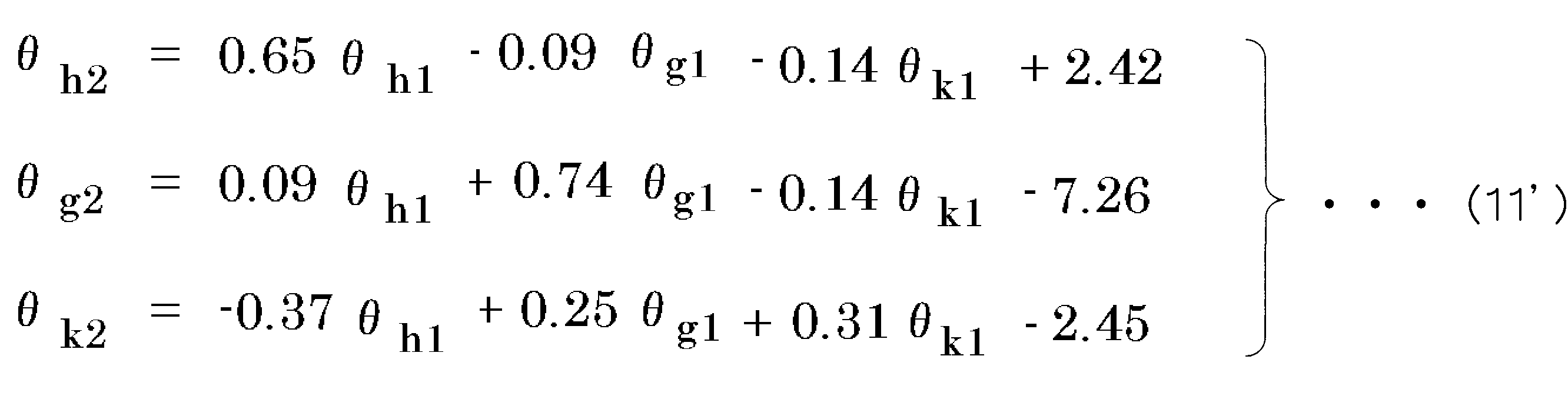
式(11')は、第1及び第2の動作における基準部位である足の動作が、同一の3つの変数で定義されるとき、それら3つの変数のうち1つの変数のみが変化する足の動作要素を含む第1の動作についての右辺と、動作要素に対応してそれら3つの変数のうち複数の変数が変化する動作成分を含む第2の動作についての左辺とを対応付けるものである。式(11)や式(11')は、基準部位である足の動作特性を反映することができる。
なお、第1のステップにおいて、複数の操作者に共通の数式を準備しても、操作者ごとに別々の数式を準備してもよい。操作者ごとに別々の数式を準備すれば、複数の操作者に共通の数式を準備する場合に比べ、個々の操作者の身体の動作特性がより正確に反映された数式を用いることができるため、個々の操作者の意図がより一層正確に反映された制御指令を生成することができる。
次に、第2及び第3のステップの具体例について説明する。
図30(a)に示すように、モニタ画面に、足の動作によって制御される制御対象三角形82と、制御対象三角形の初期姿勢83と、制御対象三角形の目標姿勢84とを表示する。初期姿勢83は、モニタ画面上に薄い色で表示されるが、図30では破線で図示している。図30(b)に示すように、被験者は、制御対象三角形82の姿勢が目標姿勢84に一致するように、制御対象三角形82を足で制御する。制御対象三角形82の姿勢が目標姿勢84に対して許容範囲内で一定時間一致すると、目標姿勢84は薄い色で表示され、次の目標姿勢84がモニタ画面に表示される。薄い色で表示された以前の目標姿勢84は、次の初期姿勢83として扱われる。以下同様に、制御対象三角形82の姿勢が目標姿勢84に対して許容範囲内で一定時間一致すると、次の目標姿勢84がモニタ画面に表示され、以前の目標姿勢84は、次の初期姿勢83として扱われる。
モニタ画面に、予め定めた目標姿勢を、順次、表示し、7番目の目標姿勢と一致すれば終了とする。終了までに要した時間と姿勢変化の正確さとを計測する。姿勢変化の正確さは、理想的な姿勢変化に対する差であり、詳しくは、制御対象三角形をi+1番目の目標姿勢に一致させる時の制御対象三角形の姿勢を(φ,θ,Ψ)、i番目の目標姿勢を(φt(i),θt(i),Ψt(i))、i+1番目の目標姿勢を(φt(i+1),θt(i+1),Ψt(i+1))と表すとき、これらを3次元空間上の座標値とみなし、(φt(i),θt(i),Ψt(i))と(φt(i+1),θt(i+1),Ψt(i+1))とを結ぶ直線に、(φ,θ,Ψ)から垂線を下し、その垂線の長さの時間平均である。姿勢変化の正確さは、数値が小さいほど、理想的な姿勢変化からのずれが小さい。
前述と同様にして足の姿勢変化動作を測定し、そのデータから、実際の足の姿勢変化動作を、実行を意図したと推定される足の姿勢変化動作に変換する数式を準備する。この数式を用いて意図した足の姿勢(第1の動作)を算出し、第1の動作に対応する姿勢となるように、モニタ画面に制御対象三角形82を表示する。
比較例2として、単純な対応付けのみに基づいて、同様の実験を行った。単純な対応付けとは、θh2はθh1のみに関係し、θh2の変化量とθh1の変化量とが比例するとし、θg2はθg1のみに関係し、θg2の変化量とθg1の変化量とが比例するとし、θk2はθk1のみに関係し、θk2の変化量とθk1の変化量とが比例するとした対応付けを意味する。
次の表2に実験結果を示す。

表2から、実施例3は、比較例2に比べ、所要時間が短く、姿勢変化が正確であることが分かる。すなわち、実施例3のような対応付けをすると、比較例2の単純な対応付けよりも、操作性が向上することが分かる。
<実施例4> 実施例4について、図33(a)及び(b)を参照しながら説明する。実施例4では、手の動きに基づいて、制御対象を動作させるための制御指令を生成する。図33(a)は、ロボットハンド等の制御対象80の動作を模式的に示す説明図である。図33(b)は、手28の基準動作を模式的に示す説明図である。
図33(a)に矢印98で示すように、ロボットハンド等の制御対象80を傾けるための制御指令と、図33(b)において矢印60で示すように、手28を傾ける動作とを対応付けると、制御対象80の動作と、制御対象80を動作させるための手28の動作との対応関係が容易に理解できるため、手28を動かして、制御対象80を容易に動作させることができる。
しかしながら、手には特有の動作特性が存在するため、制御対象を制御するときに実行することを意図した手の動作と、実際の手の動作とには、ずれが生じる。
そこで、実際の手の動作を、実行を意図したと推定される手の動作に変換するための数式を準備しておく(第1のステップ)。操作者の実際の手の動作を計測する(第2のステップ)。準備しておいた数式を用いて、計測した動作を変換し、変換した動作に含まれる基準動作の成分に基づいて、制御指令を生成する(第3のステップ)。
すなわち、前記第1のステップにおいて、制御指令と対応付けられた基準動作であって身体の基準部位を基準方向に動作させる前記基準動作を含む第1の動作と、前記第1の動作の実行を意図して動作したときの実際の動作である第2の動作とを対応付ける数式を準備する。前記第2のステップにおいて、操作者の前記基準部位の動作を計測する。前記第3のステップにおいて、前記第1のステップで準備した前記数式を用いて、前記第2のステップで計測した前記動作を変換し、変換された前記動作に含まれる前記基準動作の成分に基づいて前記制御指令を算出する。前記基準部位は、手である。
第1から第3のステップによって制御指令を算出すると、操作者の意図がより正確に反映された制御指令を生成することができる。なお、第1のステップにおいて、複数の操作者に共通の数式を準備しても、個別に、すなわち操作者ごとに別々の数式を準備してもよい。
<実施例5> 第1の動作と第2の動作との対応付けに、数式の代わりにデータベースを用いる実施例5について説明する。
例えば足首を基準部位とする場合、第1の動作における足首の位置(xv,yv,zv)とそれに対応する実際の基準部位の動作である第2の動作における足首の位置(xw,yw,zw)とを対にして1つのデータとする。第1の動作におけるi番目の位置(xvi,yvi,zvi)と、それに対応する第2の動作における位置(xwi,ywi,zwi)とを対にしたデータ(xvi,yvi,zvi,xwi,ywi,zwi)を作成する。第1の動作における様々な位置とそれに対応する第2の動作の位置の対のデータの集合からデータベースを作成する(第1のステップ)。
次いで、操作者の実際の動作、すなわち制御指令を生成するための動作を計測する(第2のステップ)。
次いで、計測した実際の動作を第2の動作として扱い、データベースの第2の動作のデータを検索し、計測した実際の動作と合致するデータ又はそれに近いデータを抽出する。合致するデータがあれば、合致したデータから第1の動作のデータを抽出する。また、合致するデータがなく、近いデータがあれば、近いデータから第1の動作のデータを抽出する、あるいは、計測した実際の動作を第2の動作としたときに対になるべき第1の動作のデータを、内挿、外挿等の手法によって補間をして得る。
次いで、抽出又は補間をして得た第1の動作のデータに含まれる基準動作の成分に基づいて制御指令を算出する(第3のステップ)。
なお、第1のステップにおいて、複数の操作者に共通のデータベースを準備しても、操作者ごとに別々のデータベースを準備してもよい。操作者ごとに別々のデータベースを準備すれば、複数の操作者に共通のデータベースを準備する場合に比べ、個々の操作者の身体の動作特性がより正確に反映されたデータベースを用いることができるため、個々の操作者の意図がより一層正確に反映された制御指令を生成することができる。
<実施例6> 実施例6について、図34~図49を参照しながら説明する。実施例6では、手の姿勢変化動作(姿勢を変える動作)に基づいて制御指令を生成する。
図34は、ロボットハンド等の制御対象80qの姿勢変化動作を模式的に示す説明図である。図35は、手28の姿勢変化動作を模式的に示す説明図である。図34(a)及び図35(a)は、上から見た図である。図34(b)及び図35(b)は、側面から見た図である。図34(c)及び図35(c)は、正面から見た図である。
図34(a)と図35(a)とを対応付け、図34(b)と図35(b)とを対応付け、図34(c)と図35(c)とを対応付けると、制御対象80qの姿勢変化動作と手28の姿勢変化動作との対応関係を容易に理解できる。
すなわち、図34(a)において矢印80aで示すように、制御対象80qをzH軸を中心に回動させる角度φHと、図35(a)において矢印28p,28qで示すように、手28を背屈(伸展)又は掌屈(屈曲)する角度である開き角θHhとを対応付ける。図34(b)において矢印80bで示すように、制御対象80qをxH軸を中心に回動させる角度θHと、図35(b)において矢印28s,28tで示すように、手28を外転又は内転する角度である仰角θHgとを対応付ける。図34(c)において矢印80cで示すように、制御対象80qをyH軸を中心に回動させる角度ΨHと、図35(c)において矢印28u,28vで示すように、手28を回内又は回外する角度である傾き角θHkとを対応付ける。角度φH,θH,ΨHの符号の定義は図34のとおりであり、開き角θHh、仰角θHg、傾き角θHkの符号の定義は図35のとおりである。
次に、手の開き角、仰角、傾き角の定義について、図36及び図37を参照しながら説明する。
図36(a)及び(b)は、右側の上肢22についての肩関節中心座標系X2-Y2-Z2(以下、sigmaSと表す。)、上肢座標系x2-y2-z2(以下、sigmaAと表す。)、手座標系x2'-y2'-z2'(以下、sigmaHと表す。)の説明図である。sigmaS、sigmaA、sigmaHは、直交座標系である。
図36(a)に示すように、背筋を伸ばし、肘関節25aを90度屈曲した基本姿勢において、sigmaSの原点OSを、右肩関節中心とする。sigmaSのX2軸は、身体10の左右の肩関節中心を通る直線に平行であり、身体10の右方向が正方向である。Z2軸は、身体10の上下方向と平行で、上向きが正方向である。Y2軸はX2軸とZ2軸とに直交しており、身体10の前方が正方向である。
図36(a)及び(b)に示すように、sigmaAにおいて、原点は、右側の手首の中心Wである。x2軸は、右肘関節の回転軸に平行であり、図36(b)の状態では、右前腕26aの内側から外側に向かう方向が正方向である。y2軸は、右側の上肢22の前腕長軸(手首中心Wと肘関節中心ELとを通る軸)に一致し、肘関節中心ELから手首中心Wに向かう方向が正方向である。z2軸は、x2軸及びy2軸に直交し、x2軸、y2軸とともに右手座標系を構成するように正方向が定義される。
図36(b)に示すように、sigmaHにおいて、原点は右側の手首中心Wである。x2'軸は、右側の手28の手のひら側と手の甲側とを結ぶ直線(右手の内側と外側とを結ぶ直線)に平行で、右側の手28の内側から外側へ向かう方向が正方向である。y2'軸は、右側の手28の第3指(中指)28cと手首中心Wとを通る直線に平行で、手首側から第3指側へと向かう方向が正方向である。z2'軸は、x2'軸とy2'軸に垂直であり、右側の手28の第5指(小指)28e側から第1指(母指)28a側に向かう方向が正方向である。手のひら面は、y2'軸とz2'軸とを含むy2'z2'平面95と平行である。図35に示すように手28の姿勢を変えると、sigmaAに対してsigmaHが回転をする。
開き角、仰角、傾き角は、sigmaAに対してsigmaHを以下の手順(1)~(3)にしたがって回転させたときの、sigmaAとsigmaHとの相対角度θHh,θHg,θHkである。
手順(1) まず、図37(a)に示すように、sigmaAとsigmaHとが一致した状態(x2軸とx2'軸とが一致し、y2軸とy2'軸とが一致し、z2軸とz2'軸とが一致する状態)から、sigmaHをy2軸まわりに角度θHkだけ回転させたものを、x2''-y2''-z2''座標系(以下、sigmaH'と表す)とする。
手順(2) 次いで、図37(b)に示すように、sigmaH'をz2''軸まわりに角度-θHhだけ回転させたものを、x2'''-y2'''-z2'''座標系(以下、sigmaH''と表す)とする。
手順(3) 次いで、図37(c)に示すように、sigmaH''をx2'''軸まわりに角度θHgだけ回転させたものを、x2''''-y2''''-z2''''座標系(以下、sigmaH'''と表す)とする。
以上の手順(1)~(3)によって、sigmaAから見たsigmaH'''の姿勢は、3つの角度の組(θHh,θHg,θHk)で表現できる。θHhが開き角であり、θHgが仰角であり、θHkが傾き角である。sigmaH'''は、開き角、仰角、傾き角が存在する状態のsigmaHを意味する。このため、sigmaAから見たsigmaH'''の姿勢は、sigmaAから見たsigmaHの姿勢を意味する。
なお、図37(a)~(c)において、回転方向を示す矢印の方向は、傾き角θHk、開き角θHh、仰角θHgが正の値となる場合の回転方向を示している。
図34(a)と図35(a)とを対応付け、図34(b)と図35(b)とを対応付け、図34(c)と図35(c)とを対応付けるといった単純な対応付けを前提とし、制御対象80qの姿勢変化動作に対応する手28の姿勢変化動作を想定し、想定した姿勢変化動作になるように手を動作させると、手28の動作をもとに制御対象80qの姿勢変化動作を制御することができる。
しかしながら、後述の図46~図49に示すように手には特有の動作特性が存在するため、制御対象を制御するときに想定した姿勢変化動作になるように手を直感的に動作させると、想定した手の姿勢変化動作と実際の手の姿勢変化動作との間には、ずれが生じる。そのため、手28の姿勢変化動作を計測し、単純な対応付けに基づいて、制御対象80qの姿勢変化動作を設定するための制御指令を生成する場合、制御対象80qに、意図した通りの正確な姿勢変化動作をさせることは、容易でない。直感的な手の動作によって、制御対象が想定した姿勢変化動作に近い姿勢変化動作をするほど、操作性が良い。
そこで、実際の手の姿勢変化動作を、実行を意図したと推定される手の姿勢変化動作に変換するための数式を準備しておき(第1のステップ)、操作者の手の姿勢変化動作を計測し(第2のステップ)、準備しておいた数式を用いて、計測した姿勢変化動作を変換し、変換した姿勢変化動作に基づいて、制御指令を生成する(第3のステップ)。
以下、さらに説明する。
実施例6では、手28を基準部位とする。図35(a)に示したように手28の開き角θHhのみを変化させる第1の基準動作と、図34(a)に示したように制御対象80qの角度φHのみを変化させる制御指令とを対応付ける。例えば、開き角θHhと角度φHとが比例関係になるように、制御指令を生成する。同様に、図35(b)に示したように手28の仰角θHgのみを変化させる第2の基準動作と、図34(b)に示した制御対象80qの角度θHのみを変化させる制御指令とを対応付ける。また、図35(c)に示したように手28の傾き角θHkのみを変化させる第3の基準動作と、図34(c)に示した制御対象80qの角度ΨHのみを変化させる制御指令とを対応付ける。
sigmaAは、原点は右側の手首の中心にあるが、x2軸、y2軸、z2軸の方向は、肘関節中心に原点があり肘関節の前腕側に固定された座標系の直交する3つの軸(肘関節の回転軸と、前腕長軸と、それらの軸と直交する軸)の方向によって定義されている。ここでは、開き角、仰角、傾き角に相当する回転方向が基準方向であり、これらは、前述のように、sigmaAにより定義される回転方向である。このため、基準方向は、基準部位である手とは異なる部位である肘関節の前腕側に一体に固定された座標系(肘関節の前腕側と一体となって同じ動きをする別の仮想的な位置に固定された座標系)であるsigmaAにより定義される回転方向となる。
以下、第1~第3のステップの具体例を説明する。
第1のステップの具体例を説明する。実際の手の姿勢変化動作を、実行を意図したと推定される手の姿勢変化動作に変換するための数式は、次のように準備する。
図38に示すように、制御対象の姿勢を三角形282(以下、「制御対象三角形282」とよぶ。)で表す。図38(b)に示すように、モニタ画面に制御対象三角形282を表示する。図38(b)は、制御対象三角形282の頂点282aと頂点282bとが頂点282qよりも手前にある状態を示す。制御対象三角形282の頂点282aから頂点282bに向かう軸は、図34の制御対象80qの根元部202を通り、上面204から下面205に向かう方向と同じ方向でかつ平行な軸に対応する。制御対象三角形282の頂点282aと頂点282bとを結ぶ底辺282cの中点282pから頂点282qに向かう軸は、図34の制御対象80qの根元部202を通り、根元部202から先端部206に向かう方向と同じ方向でかつ平行な軸に対応する。制御対象三角形282の3つの頂点282a,282b,282qを含む面の法線方向かつ図38(b)の表示では略右方向となる軸であって、制御対象三角形282の底辺282cの中点282pを通る軸は、図34の制御対象80qの根元部202を通り、左側面207から右側面208に向かう方向と同じ方向でかつ平行な軸に対応する。
モニタ画面に表示される制御対象三角形282を手28で操作していると想定する。モニタ画面に表示される制御対象三角形282の姿勢を変え、これに対応して、手28の姿勢を変える。このとき、被験者は、図34(a)と図35(a)、図34(b)と図35(b)、図34(c)と図35(c)に示した対応付けを意識して、制御対象三角形282の姿勢変化を実現させるために必要と考える通りに、手28の姿勢を変える。すなわち、図38(a)の説明図に示すように、制御対象三角形282の姿勢と手のひら面の姿勢とが一致する状況を意識して、手28の姿勢を変える。このため、モニタに表示される制御対象三角形282の動作は、被験者が意図した手28の動作を意味する。このときの手28の実際の動作(すなわち、第2の動作)を、モニタに表示された制御対象三角形282の動作(すなわち、第1の動作)と対応付けて測定する。手28の実際の動作の測定は、例えば、手28にマーカーを貼り付けた状態で手の動作を撮影し、撮影した画像を解析するなど、適宜な方法で計測すればよい。
モニタに表示する第1の動作は、図39及び図40に示すように第1乃至第3の基準動作のいずれか一つのみを含んでいてもよい。図39(a)は、制御対象80qの角度φHのみが増減する、すなわち、手の開き角θHhのみが増減する第1の基準動作について、1/4周期ごとのモニタ上の表示である。図39(b)は、制御対象80qの角度θHのみが増減する、すなわち、手の仰角θHgのみが増減する第2の基準動作について、1/4周期ごとのモニタ上の表示である。図40は、制御対象80qの角度ΨHのみが増減する、すなわち、手の傾き角θHkのみが増減する第3の基準動作について、1/4周期ごとのモニタ上の表示である。
モニタに表示する第1の動作は、複数の基準動作が含まれる複合動作であってもよいし、例えば図41及び図42に示すように基準動作の一部が動作範囲内のいずれかの状態で固定されている状態で他の基準動作が含まれる部分複合動作であってもよい。図41(a)は、制御対象80qの角度ΨHが0度、角度φHが60度に固定された状態で、角度θHのみが増減する、すなわち、手の傾き角θHkが0度、開き角θHhが60度に固定された状態で、仰角θHgのみが増減する部分複合動作について、1/4周期ごとのモニタ上の表示である。図41(b)は、制御対象80qの角度ΨHが0度、角度φHが-60度に固定された状態で、角度θHのみが増減する、すなわち、手の傾き角θHkが0度、開き角θHhが-60度に固定された状態で、仰角θHgのみが増減する部分複合動作について、1/4周期ごとのモニタ上の表示である。図42(c)は、制御対象80qの角度ΨHが0度、角度θHが15度に固定された状態で、角度φHのみが増減する、すなわち、手の傾き角θHkが0度、仰角θHgが15度に固定された状態で、開き角θHhのみが増減する部分複合動作について、1/4周期ごとのモニタ上の表示である。図42(d)は、制御対象80qの角度ΨHが0度、角度θHが-15度に固定された状態で、角度φHのみが増減する、すなわち、手の傾き角θHkが0度、仰角θHgが-15度に固定された状態で、開き角θHhのみが増減する部分複合動作について、1/4周期ごとのモニタ上の表示である。
図43~図45は、図39(a)及び(b)並びに図40に示すように第1乃至第3の基準動作のいずれか一つのみを含む第1の動作をモニタに表示したときの測定結果である。横軸は、第1の動作の変数(基準動作の開き角θHh1、仰角θHg1、傾き角θHk1のいずれか一つ)を示す。縦軸は、第2の動作の測定値(開き角θHh2、仰角θHg2、傾き角θHk2)を示す。
図43は、開き角のみを変化させる第1の基準動作に対する第2の動作の計測結果を示している。図43から、開き角のみを変化させる第1の基準動作に対して、第2の動作では開き角が変化していることが分かる。
図44は、仰角のみを変化させる第2の基準動作に対する第2の動作の計測結果を示している。図44から、仰角のみを変化させる第2の基準動作に対して、第2の動作では仰角が変化していることが分かる。
図45は、傾き角のみを変化させる第3の基準動作に対する第2の動作の計測結果を示している。図45から、傾き角のみを変化させる第3の基準動作に対して、第2の動作では傾き角が変化していることが分かる。
図46~図49は、図41及び図42に示すように部分複合動作を含む第1の動作をモニタに表示したときの測定結果である。横軸は、第1の動作の変数(開き角θHh1、仰角θHg1、傾き角θHk1のいずれか一つ)を示す。縦軸は、第2の動作の測定値(開き角θHh2、仰角θHg2、傾き角θHk2)を示す。
図46は、手の傾き角が0度、開き角が60度に固定された状態で、仰角のみを変化させる部分複合動作に対する第2の動作の計測結果を示している。図46から、仰角のみを変化させる第1の動作に対して、第2の動作では傾き角が変化していることが分かる。図46から、第1の動作の開き角が正の値となる場合には、第1の動作の変数である仰角の増加に対して、第2の動作の変数である傾き角が減少する特性を有する数式を定義することができる。
図47は、手の傾き角が0度、開き角が-60度に固定された状態で、仰角のみを変化させる部分複合動作に対する第2の動作の計測結果を示している。図47から、仰角のみを変化させる第1の動作に対して、第2の動作では傾き角が変化していることが分かる。図47から、第1の動作の開き角が負の値となる場合には、第1の動作の変数である仰角の増加に対して、第2の動作の変数である傾き角が増加する特性を有する数式を定義することができる。また、図47から、第2の動作では仰角も変化していることが分かる。
図48は、手の傾き角が0度、仰角が15度に固定された状態で、開き角のみを変化させる部分複合動作に対する第2の動作の計測結果を示している。図48から、開き角のみを変化させる第1の動作に対して、第2の動作では傾き角が変化していることが分かる。図48から、第1の動作の仰角が正の値となる場合には、第1の動作の変数である開き角の増加に対して、第2の動作の変数である傾き角が減少する特性を有する数式を定義することができる。また、図48から、第2の動作では開き角も変化していることが分かる。
図49は、手の傾き角が0度、仰角が-15度に固定された状態で、開き角のみを変化させる部分複合動作に対する第2の動作の計測結果を示している。図49から、開き角のみを変化させる第1の動作に対して、第2の動作では傾き角が変化していることが分かる。図49から、第1の動作の仰角が負の値となる場合には、第1の動作の変数である開き角の増加に対して、第2の動作の変数である傾き角が減少する特性を有する数式を定義することができる。また、図49から、第2の動作では開き角も変化していることが分かる。
一般に、第1の軸を回転中心軸として基準部位が回転運動する回転運動成分を含む第1の動作と、その第1の動作に対応する第2の動作とを対応付ける数式は、「第1の動作の回転運動成分に対応する第2の動作の成分が、第1の軸を回転中心軸とする基準部位の第1の回転運動と、第1の軸とは異なる第2の軸を回転中心軸とする基準部位の第2の回転運動とを含むこと」を取り込んだ数式である。
計測結果に対して重回帰分析を行い、第1の動作と第2の動作とを対応付ける数式を求めると、次の式(12)のようになる。ここでは、第1の動作の変数として開き角θHh1、仰角θHg1、傾き角θHk1を用い、第2の動作の変数として開き角θHh2、仰角θHg2、傾き角θHk2を用いる。

この式(12)を用いて、制御指令を算出する。すなわち、制御対象の姿勢を制御するために操作者が手を動作させたとき、手の姿勢を計測し、第2の動作に相当する手の姿勢の測定値(θHh2,θHg2,θHk2)を式(12)に代入して、第1の動作に相当する手の姿勢(θHh1,θHg1,θHk1)を算出する。算出された手の姿勢(θHh1,θHg1,θHk1)は、操作者が実行することを意図した手の姿勢に近いものになる。この(θHh1,θHg1,θHk1)を制御対象の姿勢(φH,θH,ΨH)に対応付けることにより、操作者の意図が制御対象に、より正確に反映されるようになる。
式(12)を書き直すと、次の式(12')のようになる。数値は四捨五入したものである。
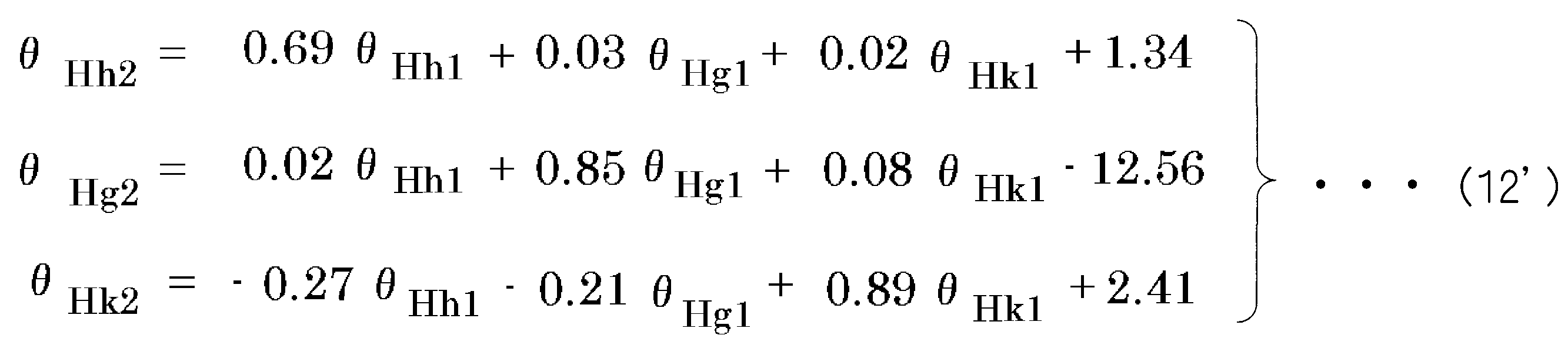
式(12')は、第1及び第2の動作における基準部位である手の動作が、同一の3つの変数で定義されるとき、それら3つの変数のうち1つの変数のみが変化する手の動作要素を含む第1の動作についての右辺と、動作要素に対応してそれら3つの変数のうち複数の変数が変化する動作成分を含む第2の動作についての左辺とを対応付けるものである。式(12)や式(12')は、基準部位である手の動作特性を反映することができる。
特に、図46~図49から、開き角と仰角とのうち少なくとも一方が変化する第1の動作に対して、傾き角が変化する第2の動作が対応することが分かる。これに基づいて、第1の動作と第2の動作とを対応付ける数式又はデータベースでは、開き角と仰角とのうち少なくとも一方が変化する手の動作要素を含む第1の動作と、この動作要素に対応して傾き角が変化する動作成分を含む第2の動作とを対応付けることができる。この場合、手の動作特性に基づいて、操作者の意図が正確に反映された制御指令を生成することができる。
なお、第1の動作と第2の動作とを対応付ける数式又はデータベースでは、開き角と仰角とのうち少なくとも一方が変化する手の動作要素を含む第1の動作と、この動作要素に対応して開き角と仰角とのうち少なくとも一方とともに傾き角も変化する動作成分を含む第2の動作とを対応付けることも可能であり、また、開き角と仰角とのうち少なくとも一方が変化する手の動作要素を含む第1の動作と、この動作要素に対応して傾き角のみが変化する動作成分を含む第2の動作とを対応付けることも可能である。
第2のステップでは、操作者の手の動作を計測する。この際、操作者は、上肢の上腕を身体の上下方向に略平行、かつ、上肢の前腕が身体の前側にあり、身体の前後方向に略平行となる姿勢をとってもよい。第3のステップでは、第2のステップで計測した動作を第2の動作として、第1のステップで準備した数式を用いて、第2のステップで計測した動作を第1の動作に変換し、変換された第1の動作に含まれる基準動作の成分に基づいて制御指令を算出する。
なお、第1のステップにおいて、複数の操作者に共通の数式又はデータベースを準備しても、操作者ごとに別々の数式又はデータベースを準備してもよい。操作者ごとに別々の数式又はデータベースを準備すれば、複数の操作者に共通の数式又はデータベースを準備する場合に比べ、個々の操作者の身体の動作特性がより正確に反映された数式又はデータベースを用いることができるため、個々の操作者の意図がより一層正確に反映された制御指令を生成することができる。
<実施例7> 実施例7について、図50~図59を参照しながら説明する。実施例7では、手の指の動きに基づいて、制御対象を動作させるための制御指令を生成する。
図50(a)は、ロボットアーム等の制御対象80rの動作を模式的に示す説明図である。図50(b)及び図50(c)は、手28を上から見た状態を示す説明図である。図50(b)は、第2指302の基準動作を示している。図50(c)は、第2指302の実際の動作を示している。図50(b)において矢印380で示すように、第2指302を少し曲げた状態で第2指302の指先312を前後方向に直線運動する基準動作と、図50(a)において矢印391で示すように、制御対象80rの前後方向の移動とを対応付ける。この対応付けを意識して第2指302を動かした場合、第2指302の指先312の実際の動作は、図50(c)において矢印381で示すように曲線運動となる。
図51(a)は、ロボットアーム等の制御対象80rの動作を模式的に示す説明図である。図51(b)及び図51(c)は、手28を横から見た状態を示す説明図である。図51(b)は、第2指302の基準動作を示している。図51(c)は、第2指302の実際の動作を示している。図51(b)において矢印382で示すように、第2指302を少し曲げた状態で第2指302の指先312を上下方向に直線運動する基準動作と、図51(a)において矢印392で示すように、制御対象80rの上下方向の移動とを対応付ける。この対応付けを意識して第2指302を動かした場合、第2指302の指先312の実際の動作は、図51(c)において矢印383で示すように曲線運動となる。
図52(a)は、ロボットアーム等の制御対象80rの動作を模式的に示す説明図である。図52(b)は、手28を上から見た状態を示す説明図である。図52(b)は、第2指302の基準動作を示している。図52(b)において矢印384で示すように、第2指302を少し曲げた状態で第2指302の指先312を左右方向に直線運動する基準動作と、図52(a)において矢印393で示すように、制御対象80rの左右方向の移動とを対応付ける。
図53(a)は、ロボットアーム等の制御対象80rの動作を模式的に示す説明図である。図53(b)及び図53(c)は、手28を横から見た状態を示す説明図である。図53(b)は、第1指301の基準動作を示している。図53(c)は、第1指301の実際の動作を示している。図53(b)において矢印370で示すように、第1指301を少し曲げた状態で第1指301の指先311を上下方向に直線運動する基準動作と、図53(a)において矢印394で示すように、制御対象80rの上下方向の移動とを対応付ける。この対応付けを意識して第1指301を動かした場合、第1指301の指先311の実際の動作は、図53(c)において矢印371で示すように曲線運動となる。
図54(a)は、ロボットアーム等の制御対象80rの動作を模式的に示す説明図である。図54(b)及び図54(c)は、手28を上から見た状態を示す説明図である。図54(b)は、第1指301の基準動作を示している。図54(c)は、第1指301の実際の動作を示している。図54(b)において矢印372で示すように、第1指301を少し曲げた状態で第1指301の指先311を左右方向に直線運動する基準動作と、図54(a)において矢印395で示すように、制御対象80rの左右方向の移動とを対応付ける。この対応付けを意識して第1指301を動かした場合、第1指301の指先311の実際の動作は、図54(c)において矢印373で示すように曲線運動となる。
図55(a)は、ロボットアーム等の制御対象80rの動作を模式的に示す説明図である。図55(b)は、手28を横から見た状態を示す説明図である。図55(b)は、第1指301の基準動作を示している。図55(b)において矢印374で示すように、第1指301を少し曲げた状態で第1指301の指先311を前後方向に直線運動する基準動作と、図55(a)において矢印396で示すように、制御対象80rの前後方向の移動とを対応付ける。
このような手の指の動作特性が反映されるように、以下の第1乃至第3のステップによって、制御指令を生成する。
第1のステップでは、基準部位である指先の動作を計測し、第1の動作と第2の動作とを対応付ける数式又はデータベースを準備する。基準部位である指先の計測は、直接的に指先の動作を計測する方法だけでなく、指先と連動して動く他の部位である末節骨や中節骨、基節骨、中手骨などの動作を計測し、それから指先の動作を算出する間接的な方法でもよい。
第2のステップでは、操作者の指先の動作を計測する。この際、操作者は、上肢の上腕を身体の上下方向に略平行、かつ、上肢の前腕が身体の前側にあり、上肢の前腕が身体の前後方向に略平行となる姿勢をとってもよい。
第3のステップでは、第2のステップで計測した動作を第2の動作として、第1のステップで準備した数式又はデータベースを用いて、第2のステップで計測した動作を第1の動作に変換し、変換された第1の動作に含まれる基準動作の成分に基づいて制御指令を算出する。
なお、第1のステップにおいて、複数の操作者に共通の数式又はデータベースを準備しても、操作者ごとに別々の数式又はデータベースを準備してもよい。操作者ごとに別々の数式又はデータベースを準備すれば、複数の操作者に共通の数式又はデータベースを準備する場合に比べ、個々の操作者の身体の動作特性がより正確に反映された数式又はデータベースを用いることができるため、個々の操作者の意図がより一層正確に反映された制御指令を生成することができる。
次に、第1のステップで準備する数式又はデータベースを決定するための実験4について説明する。
実験4では、被験者は、上肢の上腕を身体の上下方向に略平行、かつ、上肢の前腕が身体の前側にあり、上肢の前腕が身体の前後方向に略平行となる姿勢をとる。手首は曲げずに、図51(b)及び(c)、図53(b)及び(c)に示すように、手28は第2指302が上側で第5指305が下側となる状態とする。第2指302の指先312を基準部位とする場合には、図50(b)および図51(b)に示すように、手28を軽く握った状態から第2指302のみを少し伸ばした(伸展させた)状態を指の基本姿勢とした。第1指301の指先311を基準部位とする場合には、図53(b)および図54(b)に示すように、手を軽く開いた状態から第1指301を少し曲げた状態を指の基本姿勢とした。
そして、被験者の前に目標物を表示するモニターを配置し、モニター上で目標物を所定方向に移動させる。目標物は制御対象に相当するものとして扱う。モニター上には、目標物が前後、左右、上下に移動する映像が表示され、被験者は指と制御対象との対応付けを意識し、映像に合わせて指を動かす。
すなわち、第2指302の指先312を基準部位とする場合には、被験者は、図50(a)及び(b)、図51(a)及び(b)、図52(a)及び(b)に示した対応付けを意識して、目標物の移動を実現させるために必要と考える通りに、第2指302を動かす。第1指301の指先311を基準部位とする場合には、図53(a)及び(b)、図54(a)及び(b)、図55(a)及び(b)に示した対応付けを意識して、目標物の移動を実現させるために必要と考える通りに、第1指301を動かす。指の動きは、被験者の指を撮影した画像を解析することによって計測した。
ここで、図50(b)の矢印380あるいは図55(b)の矢印374で示す前後方向に相当する方向を、「手首第3指方向」と呼ぶ。手首第3指方向は、拳を握った状態において手首関節中心と第3指の基節骨とを結ぶ方向と平行な方向であり、手首関節中心から第3指の基節骨に向かう方向を正方向とする。
また、図51(b)の矢印382あるいは図53(b)の矢印370で示す上下方向に相当する方向を、「第5指第2指方向」と呼ぶ。第5指第2指方向は、第2指302乃至第5指305で軸状部材を握ったときに軸状部材の中心軸の方向と平行な方向であり、第5指305から第2指302に向かう方向を正方向とする。
また、図52(b)の矢印384あるいは図54(b)の矢印372で示す左右方向に相当する方向を、「手のひら甲方向」と呼ぶ。手のひら甲方向は、手のひらと手の甲との間を貫通する方向と平行な方向であり、手のひらから手の甲に向かう方向を正方向とする。手首第3指方向、第5指第2指方向、手のひら甲方向は、互いに垂直な方向となる。
図56は、図50(a)において矢印391で示すような目標物(制御対象80r)の前後方向の直線状の移動に対応して、図50(a)及び(b)に示した対応付けを意識して被験者が第2指302を動かしたときの実験結果を示すグラフである。すなわち、実験の際、被験者は、目標物の前後方向の直線状の移動と同じように、第2指302の指先312を前後方向(手首第3指方向)に直線状に動かすことを意図して、第2指302を動かした。図56において、横軸は、第2指の指先の左右方向(手のひら甲方向)の位置を示し、縦軸は第2指の指先の前後方向(手首第3指方向)の位置を示す。原点は指の基本姿勢での第2指の指先の位置を示す。
図56から、第2指の指先は曲線運動をしており、第2指の指先の曲線運動の曲線は、第2指のPIP関節の曲げ伸ばし運動の回転中心軸と平行となる方向に見ると、第2指のPIP関節と第2指のDIP関節とのうち少なくとも一方が曲線の内側となるように曲がっていることがわかる。すなわち、被験者は、図50(b)において矢印380で示すように第2指302の指先312を直線状に動かそうと意図したが、実際の動作は、図50(c)において矢印381で示すように曲線状の動作となり、第2指302のPIP関節302pの曲げ伸ばし運動の回転中心軸と平行となる方向に見ると、第2指302のPIP関節302pと第2指302のDIP関節302dの少なくとも一方が、第2指302の指先312が曲線運動する曲線の内側に対向する、換言すると、その凸状の曲線に関して凹側にある。
したがって、基準部位が手の第2指の指先であり、手の手首関節中心から手の第3指の基節骨に向かう方向と平行に第2指の指先が直線運動する直線運動成分を含む第1の動作と第1の動作に対応する第2の動作とを対応付ける数式又はデータベースは、「直線運動成分に対応する第2の動作の成分は第2指の指先が曲線運動する曲線運動成分であり、曲線運動成分の曲線は、第2指のPIP関節の曲げ伸ばし運動の回転中心軸と平行となる方向に見ると、第2指のPIP関節と第2指のDIP関節とのうち少なくとも一方が曲線の内側に対向するように曲がっていること」を取り込んだ数式又はデータベースとすればよい。すなわち、「直線運動成分に対応する第2の動作の成分は第2指の指先が曲線運動する曲線運動成分であり、曲線運動成分の曲線は、第2指のPIP関節の曲げ伸ばし運動の回転中心軸と平行となる方向に見ると、凸状又は凹状の曲線であり、曲線の両端を通る直線で二分される領域のうち曲線が存在しない一方の領域と、曲線および直線(曲線の両端を通る直線)によって囲まれる領域と、直線(曲線の両端を通る直線)上とのうち少なくとも一つに、第2指のPIP関節と第2指のDIP関節とのうち少なくとも一方があること」を、数式又はデータベースに取り込む。例えば、第2の動作の成分が、第2指のDIP関節や第2指のPIP関節や第2指のMP関節の曲げ伸ばし運動により生じる第2指の指先の曲線運動や、一つの円弧に沿う円弧状の曲線運動や、略円弧状の曲線運動となることを取り込んだ数式などであっても構わない。
図57は、図51(a)において矢印392で示すような目標物(制御対象80r)の上下方向の直線状の移動に対応して、図51(a)及び(b)に示した対応付けを意識して被験者が第2指302を動かしたときの実験結果を示すグラフである。すなわち、実験の際、被験者は、目標物の上下方向の直線状の移動と同じように、第2指302の指先312を上下方向(第5指第2指方向)に直線状に動かすことを意図して、第2指302を動かした。図57において、横軸は、第2指の指先の前後方向(手首第3指方向)の位置を示し、縦軸は第2指の指先の上下方向(第5指第2指方向)の位置を示す。原点は指の基本姿勢での第2指の指先の位置を示す。
図57から、第2指の指先は曲線運動をしており、第2指の指先の曲線運動の曲線は、第2指のMP関節中心を通るとともに第2指のPIP関節の曲げ伸ばし運動の回転中心軸と第2指のMP関節中心とを含む平面に垂直となる仮想直線と平行となる方向に見ると、仮想直線に第2指の指先から下した垂線の足となる点が曲線の内側となるように曲がっていることがわかる。すなわち、被験者は、図51(b)において矢印382で示すように第2指302の指先312を直線状に動かそうと意図したが、実際の動作は、図51(c)において矢印383で示すように曲線状の動作となり、第2指302のMP関節302mの中心を通るとともに第2指302のPIP関節302pの曲げ伸ばし運動の回転中心軸と第2指302のMP関節302mの中心とを含む平面に垂直となる仮想直線350と平行となる方向に見ると、仮想直線に第2指302の指先312から下した垂線の足となる点352が、第2指302の指先312が曲線運動する曲線の内側に対向する、換言すると、その凸状の曲線に関して凹側にある。
したがって、基準部位が手の第2指の指先であり、手の第5指から手の第2指に向かう方向と平行に第2指の指先が直線運動する直線運動成分を含む第1の動作と第1の動作に対応する第2の動作とを対応付ける数式又はデータベースは、「直線運動成分に対応する第2の動作の成分は第2指の指先が曲線運動する曲線運動成分であり、曲線運動成分の曲線は、第2指のMP関節中心を通るとともに第2指のPIP関節の曲げ伸ばし運動の回転中心軸と第2指のMP関節中心とを含む平面に垂直となる仮想直線と平行となる方向に見ると、仮想直線に第2指の指先から下した垂線の足となる点が曲線の内側に対向するように曲がっていること」を取り込んだ数式又はデータベースとすればよい。すなわち、「直線運動成分に対応する第2の動作の成分は第2指の指先が曲線運動する曲線運動成分であり、曲線運動成分の曲線は、第2指のMP関節中心を通るとともに第2指のPIP関節の曲げ伸ばし運動の回転中心軸と第2指のMP関節中心とを含む平面に垂直となる仮想直線と平行となる方向に見ると、凸状又は凹状の曲線であり、曲線の両端を通る直線で二分される領域のうち曲線が存在しない一方の領域と、曲線および直線(曲線の両端を通る直線)によって囲まれる領域と、直線(曲線の両端を通る直線)上とのうち少なくとも一つに、仮想直線に第2指の指先から下した垂線の足となる点があること」を、数式又はデータベースに取り込む。例えば、第2の動作の成分が、第2指のMP関節の内転・外転運動により生じる第2指の指先の曲線運動や、一つの円弧に沿う円弧状の曲線運動や、略円弧状の曲線運動となることを取り込んだ数式などであっても構わない。
図58は、図53(a)において矢印394で示すような目標物(制御対象80r)の上下方向の直線状の移動に対応して、図53(a)及び(b)に示した対応付けを意識して被験者が第1指301を動かしたときの実験結果を示すグラフである。すなわち、実験の際、被験者は、目標物の上下方向の直線状の移動と同じように、第1指301の指先311を上下方向(第5指第2指方向)に直線状に動かすことを意図して、第1指301を動かした。図58において、横軸は、第1指の指先の前後方向(手首第3指方向)の位置を示し、縦軸は第1指の指先の上下方向(第5指第2指方向)の位置を示す。原点は指の基本姿勢での第1指の指先の位置を示す。
図58から、第1指の指先は曲線運動をしており、第1指の指先の曲線運動の曲線は、第1指のIP関節の曲げ伸ばし運動の回転中心軸と平行となる方向に見ると、第1指のIP関節と、第1指のMP関節と、第1指の手根中手関節とのうち少なくとも一つが曲線の内側となるように曲がっていることがわかる。すなわち、被験者は、図53(b)において矢印370で示すように第1指301の指先311を直線状に動かそうと意図したが、実際の動作は、図53(c)において矢印371で示すように曲線状の動作となり、第1指301のIP関節301iの曲げ伸ばし運動の回転中心軸と平行となる方向に見ると、第1指301のIP関節301iと、第1指301のMP関節301mと、第1指301の手根中手関節301kとのうち少なくとも一つが、第1指301の指先311が曲線運動する曲線の内側に対向する、換言すると、その凸状の曲線に関して凹側にある。
したがって、基準部位が手の第1指の指先であり、手の第5指から手の第2指に向かう方向と平行に第1指の指先が直線運動する直線運動成分を含む第1の動作と第1の動作に対応する第2の動作とを対応付ける数式又はデータベースは、「直線運動成分に対応する第2の動作の成分は第1指の指先が曲線運動する曲線運動成分であり、曲線運動成分の曲線は、第1指のIP関節の曲げ伸ばし運動の回転中心軸と平行となる方向に見ると、第1指のIP関節と、第1指のMP関節と、第1指の手根中手関節とのうち少なくとも一つが曲線の内側に対向するように曲がっていること」を取り込んだ数式又はデータベースとすればよい。すなわち、「直線運動成分に対応する第2の動作の成分は第1指の指先が曲線運動する曲線運動成分であり、曲線運動成分の曲線は、第1指のIP関節の曲げ伸ばし運動の回転中心軸と平行となる方向に見ると、凸状又は凹状の曲線であり、曲線の両端を通る直線で二分される領域のうち曲線が存在しない一方の領域と、曲線および直線(曲線の両端を通る直線)によって囲まれる領域と、直線(曲線の両端を通る直線)上とのうち少なくとも一つに、第1指のIP関節と、第1指のMP関節と、第1指の手根中手関節とのうち少なくとも一つがあること」を、数式又はデータベースに取り込む。例えば、第2の動作の成分が、第1指のIP関節や第1指のMP関節の曲げ伸ばし運動や第1指の手根中手関節の橈側外転・尺側内転運動により生じる第1指の指先の曲線運動や、一つの円弧に沿う円弧状の曲線運動や、略円弧状の曲線運動となることを取り込んだ数式などであっても構わない。
図59は、図54(a)において矢印395で示すような目標物(制御対象80r)の左右方向の直線状の移動に対応して、図54(a)及び(b)に示した対応付けを意識して被験者が第1指301を動かしたときの実験結果を示すグラフである。すなわち、実験の際、被験者は、目標物の左右方向の直線状の移動と同じように、第1指301の指先311を左右方向(手のひら甲方向)に直線状に動かすことを意図して、第1指301を動かした。図59において、横軸は、第1指の指先の前後方向(手首第3指方向)の位置を示し、縦軸は第1指の指先の左右方向(手のひら甲方向)の位置を示す。原点は指の基本姿勢での第1指の指先の位置を示す。
図59から、第1指の指先は曲線運動をしており、第1指の指先の曲線運動の曲線は、第1指の手根中手関節の掌側外転・掌側内転運動の回転中心軸と平行となる方向に見ると、第1指の手根中手関節が曲線の内側となるように曲がっていることがわかる。すなわち、被験者は、図54(b)において矢印372で示すように第1指301の指先311を直線状に動かそうと意図したが、実際の動作は、図54(c)において矢印373で示すように曲線状の動作となり、第1指301の手根中手関節301kの掌側外転・掌側内転運動の回転中心軸と平行となる方向に見ると、第1指301の手根中手関節301kが、第1指301の指先311が曲線運動する曲線の内側に対向する、換言すると、その凸状の曲線に関して凹側にある。
したがって、基準部位が手の第1指の指先であり、手の手のひらから手の甲に向かう方向と平行に第1指の指先が直線運動する直線運動成分を含む第1の動作と第1の動作に対応する第2の動作とを対応付ける数式又はデータベースは、「直線運動成分に対応する第2の動作の成分は第1指の指先が曲線運動する曲線運動成分であり、曲線運動成分の曲線は、第1指の手根中手関節の掌側外転・掌側内転運動の回転中心軸と平行となる方向に見ると、第1指の手根中手関節が曲線の内側に対向するように曲がっていること」を取り込んだ数式又はデータベースとすればよい。すなわち、「直線運動成分に対応する第2の動作の成分は第1指の指先が曲線運動する曲線運動成分であり、曲線運動成分の曲線は、第1指の手根中手関節の掌側外転・掌側内転運動の回転中心軸と平行となる方向に見ると、凸状又は凹状の曲線であり、曲線の両端を通る直線で二分される領域のうち曲線が存在しない一方の領域と、曲線および直線(曲線の両端を通る直線)によって囲まれる領域と、直線(曲線の両端を通る直線)上とのうち少なくとも一つに、第1指の手根中手関節があること」を、数式又はデータベースに取り込む。例えば、第2の動作の成分が、第1指の手根中手関節の掌側外転・掌側内転運動により生じる第1指の指先の曲線運動や、一つの円弧に沿う円弧状の曲線運動や、略円弧状の曲線運動となることを取り込んだ数式などであっても構わない。
図56~図59は、手の姿勢が第2指が上側で第5指が下側となる場合の実験4の結果であったが、手の姿勢が手のひらが下向きで手の甲が上向きとなる場合の実験5や、手の姿勢が手のひらが上向きで手の甲が下向きとなる場合の実験6も行った。その結果、手の姿勢の変化による方向の定義の変化を考慮すれば、図56~図59と同様の結果が得られた。すなわち、手首第3指方向の実験結果に相当する実験5での前後方向及び実験6での前後方向の実験結果は、実験4での前後方向の実験結果と同様の結果となり、手のひら甲方向の実験結果に相当する実験5での上下方向及び実験6での上下方向の実験結果は、実験4での左右方向の実験結果と同様の結果となり、第5指第2指方向の実験結果に相当する実験5での左右方向及び実験6での左右方向の実験結果は、実験4での上下方向の実験結果と同様の結果となった。このため、図56~図59は、手の姿勢の変化に関わらずに生じる指の動作特性を表すものと言える。手首第3指方向、第5指第2指方向、手のひら甲方向で方向を定義すると、手の姿勢に関わらず指の動作特性を共通に扱いやすい。なお、手首を曲げたり前腕や上腕の姿勢を変えて手の姿勢を変えた場合でも、実験4で得られた指の動作特性を取り込んだ数式又はデータベースを用いてもよい。
手首第3指方向は、手の手のひら乃至甲に固定された座標系において手の手首関節中心から手の第2~5指の基節骨が動きうる範囲内に向かうように予め定めた一つの方向定義直線と平行な方向、と定義してもよい。第5指第2指方向は、手の手のひら乃至甲に固定された座標系において手の第5指の基節骨が動きうる範囲内から手の第2指の基節骨が動きうる範囲内に向かうように予め定めた一つの方向定義直線と平行な方向、と定義してもよい。手のひら甲方向は、手の手のひら乃至甲に固定された座標系において手の手のひらから手の甲に向かうように予め定めた一つの方向定義直線と平行な方向、と定義してもよい。
第3~5指の動作特性は、実験4で明らかになった第2指の動作特性と同様である。このため、第3~5指の指先を基準部位とする場合は、第2指の指先を基準部位とする場合と同様の方法で、指の動作特性を取り込んだ数式又はデータベースとすればよい。また、基準部位を第2~5指のDIP関節よりも指先側の部位とする場合でも第2~5指の指先を基準部位とする場合と同様の動作特性となり、基準部位を第1指のIP関節よりも指先側の部位とする場合でも第1指の指先を基準部位とする場合と同様の動作特性となるため、基準部位を第2~5指のDIP関節よりも指先側の部位とする場合や基準部位を第1指のIP関節よりも指先側の部位とする場合は、指先を基準部位とする場合と同様の方法で、指の動作特性を取り込んだ数式又はデータベースとすればよい。
第1の動作と第2の動作とを対応付ける数式は種々のパラメータを用いても構わない。指先の位置のパラメータとして、手首第3指方向、第5指第2指方向、手のひら甲方向の指先の位置を表すパラメータや、指のPIP関節、DIP関節、MP関節、IP関節、第1指の手根中手関節などの各関節の回転角度を表すパラメータを用いてもよい。回帰分析(単回帰分析や重回帰分析)を用いて、目標物の位置のパラメータと実際の指先の位置のパラメータとの関係式を求めてもよい。第1の動作には、斜め方向などの複合動作を含めてもよい。
ここで、第1及び第2の動作における第2指の指先の動作が、どちらも、指先の前後、左右、上下方向の位置を表す変数(同一の複数の変数)で定義される場合を考える。この場合、例えば、図50(b)に示すように、指先の前後方向の位置を表す変数のみが変化する第1の動作に対して、図50(c)に示すように、指先の前後方向の位置を表す変数と指先の左右方向の位置を表す変数の2つの変数が変化する第2の動作が対応するため、これらを対応付ける数式とすればよい。すなわち、第1及び第2の動作における基準部位の動作が、同一の複数の変数で定義されるとき、第1の動作と第2の動作とを対応付ける数式又はデータベースは、それらの変数のうち1つの変数のみが変化する基準部位の動作要素を含む第1の動作と、この動作要素に対応してそれらの変数のうち複数の変数が変化する動作成分を含む第2の動作とを対応付けるものである。図51の第2指の上下方向の位置を表す変数のみが変化する第1の動作の場合でも、図53の第1指の上下方向の位置を表す変数のみが変化する第1の動作の場合でも、図54の第1指の左右方向の位置を表す変数のみが変化する第1の動作の場合でも、同様である。
<実施例8> 実施例8の制御指令生成装置400について、図60を参照しながら説明する。
図60は、制御指令生成装置400のブロック図である。図60に示すように、制御指令生成装置400は、制御部402に、表示部412と、操作部414と、測定部416と、記憶部422と、演算部424と、インターフェース部426とを備える。
制御部402は、制御指令生成装置400全体の制御を統括する。表示部412は、例えば、表示パネル等を含み、制御指令生成装置400の動作状況を表示する。操作部414は、例えば、ボタンやスイッチなどを含み、起動・停止、データ入力、モード選択などの操作を受け付ける。測定部416は、例えば、カメラやセンサなどを含み、操作者の基準部位の動作を測定し、測定データを制御部402に送出する。記憶部422には、制御部402や演算部424を動作させるためのプログラムについてのプログラムデータや、基準動作を含む第1の動作と、第1の動作に対応する基準部位の実際の動作である第2の動作とを対応付ける数式を定義する第1のデータ、又は第1の動作と第2の動作とを対応付けるデータベースを構成する第2のデータなどが格納される。演算部424は、測定部416からの測定データと記憶部422に格納された第1又は第2のデータとを用いて演算を行う。インターフェース部426は、外部機器とデータを送受信するためのインターフェースであり、記憶部422に格納するためのプログラムデータや第1又は第2のデータ、演算部424からの演算結果データなどを受け付け、入出力を行う。
制御指令生成装置400は、記憶部422に格納されたプログラムデータに基づいて動作する。
すなわち、測定部416は、操作者の基準部位の動作を測定し、測定データを制御部402に送出する。制御部402は、操作者の基準部位の動作を計測した測定データの入力を受け付ける入力受付部として機能する。なお、測定部416は、制御指令生成装置400から分離された別個の装置とすることも可能である。
演算部424は、記憶部422に格納された第1又は第2のデータと制御部402が入力を受け付けた測定データとを参照し、制御部402が測定データの入力を受け付けた操作者の基準部位の動作を第2の動作として、記憶部422に第1又は第2のデータが格納された数式又はデータベースを用いることによって、制御部402が測定データの入力を受け付けた操作者の基準部位の動作を第1の動作に変換し、変換された第1の動作に含まれる基準動作の成分に基づいて制御指令を算出する。演算部424は、制御指令算出部として機能する。
演算部424が算出した制御指令のデータは、制御部402を介してインターフェース部426に伝達され、インターフェース部426から不図示の制御対象に制御信号が送出される。
基準動作を含む第1の動作の実行を意図して動作したときに、実際に動作される第2の動作と、動作することを意図された第1の動作との間には、ずれが生じる。第1の動作と第2の動作とを対応付ける数式又はデータベースを準備し、この数式又はデータベースに基づいて、操作者の実際の動作を変換すると、変換された動作は、操作者が実行することを意図した動作又はそれに近い動作になる。そのため、変換された動作に含まれる基準動作の成分に基づいて制御指令を算出すると、操作者の意図がより正確に反映された制御指令を生成することができる。
なお、記憶部422には、複数の操作者に共通の第1又は第2のデータが格納されても、操作者ごとに別々の第1又は第2のデータが格納されてもよい。操作者ごとに別々の第1又は第2のデータを格納すれば、複数の操作者に共通の第1又は第2のデータが格納される場合に比べ、個々の操作者の身体の動作特性がより正確に反映された数式又はデータベースを用いることができるため、個々の操作者の意図がより一層正確に反映された制御指令を生成することができる。
また、制御部402が入力を受け付ける測定データは、基準部位そのものの動作を直接的に計測した測定データであっても、基準部位と連動して動く他の部位の動作を計測し、他の部位の動作の計測結果から基準部位の動作を算出した間接的な測定データであってもよい。
<まとめ> 以上に説明したように、操作者の実際の動作を変換し、変換した動作に基づいて制御指令を生成すると、操作者の意図がより正確に反映された制御指令を生成することができる。
なお、本発明は、上記実施の形態に限定されるものではなく、種々変更を加えて実施することが可能である。
例えば、基準方向は、前後、左右、上下に限らず、斜め方向としてもよい。
実施例1などの上記実施の形態では、制御指令である制御対象の動作と、基準動作とが略同じとなるような対応付けとなる例を示したが、それ以外でも構わない。基準動作に対応付けられる制御指令は様々なものが可能である。基準動作の位置や姿勢を、制御対象の位置や姿勢と対応付ける例以外にも、制御対象の移動速度や姿勢変化速度に対応付けることや、制御対象が出力する力やトルクの大きさに対応付けることや、制御対象が出す音や光や振動の強さや方向と対応付けることなども可能である。基準動作の姿勢を制御対象の位置と対応付けることや、基準動作の位置を制御対象の姿勢と対応付けることも可能である。基準動作の速度、加速度、角速度、角加速度等を制御指令に対応付けてもよい。
また、実施例では右側の上肢及び下肢を基準部位とする例を用いて説明したが、左側の上肢や下肢を使う場合でも、可能である。その対称性を考慮して、同様に定義すればよい。実施例では足首、足、手首、手、指先を基準部位とする例を用いて説明したが、膝関節より足側の他の部位や、肘関節より手側の他の部位、その他の部位を基準部位としてもよい。例えば、実施例2では、手首ではなく、指先や指、手を基準部位としてもよい。また、基準部位として頚部や頭部を用いてもよい。基準部位は、頭部に含まれている、舌、口(上唇、下唇、口角)、顎、歯、目などでもよい。数式やデータベースは、身体の動作を計測したデータに基づいて準備する方法だけでなく、身体に関してこれまでに得られている知見や、身体に関するシミュレーションや解析の結果より得られる情報などに基づいて準備してもよい。
上記実施の形態では、身体の動作に基づく制御指令生成方法の第2のステップにおいて、操作者の基準部位の動作を計測する場合を説明したが、第2のステップにおいて、操作者の基準部位の動作を計測したデータを取得してもよい。この場合、第3のステップでは、第2のステップでデータを取得した動作を第2の動作として数式又はデータベースを用いることによって、第2のステップでデータを取得した動作を第1の動作に変換し、変換された第1の動作に含まれる基準動作の成分に基づいて制御指令を算出する。
本発明は、操作者の基準部位の動作に基づいて、操作者の意図が正確に反映された制御指令を生成することができる。そのため、乗り物、移動装置、ロボット、探査装置、機械装置などの実物の操作や遠隔操作、画面上の物体を動かす制御指令を生成することによる画面上の操作、パソコンやコンピュータやスマートフォンやタブレット端末やテレビやカーナビゲーションシステムやゲームや情報機器や情報端末などへの入力、画面表示を利用したリハビリテーションなどに適用できる。
10 身体
12 下肢
14 大腿
16 下腿
17 足首
18 足
22 上肢
24 上腕
25 肘
26 前腕
27 手首
28 手
80,80p,80q,80r 制御対象
82,282 制御対象三角形
301 第1指
301i IP関節
301k 手根中手関節
301m MP関節
302 第2指
302d DIP関節
302m MP関節
302p PIP関節
311,312 指先
400 制御指令生成装置
402 制御部(入力受付部)
422 記憶部
424 演算部(制御指令算出部)
O1 股関節中心
O2 膝関節中心
O3 足首中心
O1u 肩関節中心
O2u 肘関節中心
O3u 手首中心
12 下肢
14 大腿
16 下腿
17 足首
18 足
22 上肢
24 上腕
25 肘
26 前腕
27 手首
28 手
80,80p,80q,80r 制御対象
82,282 制御対象三角形
301 第1指
301i IP関節
301k 手根中手関節
301m MP関節
302 第2指
302d DIP関節
302m MP関節
302p PIP関節
311,312 指先
400 制御指令生成装置
402 制御部(入力受付部)
422 記憶部
424 演算部(制御指令算出部)
O1 股関節中心
O2 膝関節中心
O3 足首中心
O1u 肩関節中心
O2u 肘関節中心
O3u 手首中心
Claims (20)
- 身体の基準部位を基準方向に動作させる基準動作と制御指令とを対応付け、前記基準部位の動作をもとに前記制御指令を生成する、身体の動作に基づく制御指令生成方法であって、
前記基準動作を含む第1の動作と、前記第1の動作に対応する前記基準部位の実際の動作である第2の動作とを対応付ける数式又はデータベースを準備する第1のステップと、
操作者の前記基準部位の動作を計測する第2のステップと、
前記第2のステップで計測した前記動作を前記第2の動作として前記数式又は前記データベースを用いることによって、前記第2のステップで計測した前記動作を前記第1の動作に変換し、変換された前記第1の動作に含まれる前記基準動作の成分に基づいて前記制御指令を算出する第3のステップと、
を備えたことを特徴とする、身体の動作に基づく制御指令生成方法。 - 身体の基準部位を基準方向に動作させる基準動作と制御指令とを対応付け、前記基準部位の動作をもとに前記制御指令を生成する、身体の動作に基づく制御指令生成方法であって、
前記基準動作を含む第1の動作と、前記第1の動作に対応する前記基準部位の実際の動作である第2の動作とを対応付ける数式又はデータベースを準備する第1のステップと、
操作者の前記基準部位の動作を計測したデータを取得する第2のステップと、
前記第2のステップで前記データを取得した前記動作を前記第2の動作として前記数式又は前記データベースを用いることによって、前記第2のステップで前記データを取得した前記動作を前記第1の動作に変換し、変換された前記第1の動作に含まれる前記基準動作の成分に基づいて前記制御指令を算出する第3のステップと、
を備えたことを特徴とする、身体の動作に基づく制御指令生成方法。 - 前記第1及び第2の動作における前記基準部位の動作が、同一の複数の変数で定義されるとき、
前記第1のステップにおいて準備する前記数式又は前記データベースは、
前記変数のうち1つのみが変化する前記基準部位の動作要素を含む前記第1の動作と、前記動作要素に対応して前記変数のうち複数が変化する動作成分を含む前記第2の動作とを対応付けるものであることを特徴とする、請求項1又は2に記載の身体の動作に基づく制御指令生成方法。 - 前記基準部位は、下肢と、上肢と、頚部及び頭部とのうち、少なくとも一つに含まれることを特徴とする、請求項1乃至3のいずれか一つに記載の身体の動作に基づく制御指令生成方法。
- 前記基準部位が直線運動する運動成分を含む前記第1の動作と該第1の動作に対応する前記第2の動作とを対応付ける前記数式又は前記データベースは、
前記運動成分に対応する前記第2の動作の成分が、前記基準部位の曲線運動となることを取り込んだ数式又はデータベースであることを特徴とする、請求項1乃至4のいずれか一つに記載の身体の動作に基づく制御指令生成方法。 - 前記基準部位は、膝関節より足側の部位であり、
前記基準部位が前記身体の前後方向に直線運動する直線運動成分を含む前記第1の動作と該第1の動作に対応する前記第2の動作とを対応付ける前記数式又は前記データベースは、
前記直線運動成分に対応する前記第2の動作の成分が、前記膝関節の曲げ伸ばし運動の回転中心軸と平行となる方向に見ると、前記膝関節側を内側とするように曲がった前記基準部位の曲線運動となることを取り込んだ数式又はデータベースであることを特徴とする、請求項1乃至5のいずれか一つに記載の身体の動作に基づく制御指令生成方法。 - 前記基準部位は、膝関節より足側の部位であり、
前記基準部位が前記身体の左右方向に直線運動する直線運動成分を含む前記第1の動作と該第1の動作に対応する前記第2の動作とを対応付ける前記数式又は前記データベースは、
前記直線運動成分に対応する前記第2の動作の成分が、前記膝関節を含む下肢の股関節と前記膝関節とを結ぶ軸と平行となる方向に見ると、前記膝関節側を内側とするように曲がった前記基準部位の第1の曲線運動と、前記身体の上方から見ると、前記股関節側を内側とするように曲がった前記基準部位の第2の曲線運動とのうち、少なくとも一方を含む曲線運動となることを取り込んだ数式又はデータベースであることを特徴とする、請求項1乃至5のいずれか一つに記載の身体の動作に基づく制御指令生成方法。 - 前記基準部位は、膝関節より足側の部位であり、
前記基準部位が前記身体の上下方向に直線運動する直線運動成分を含む前記第1の動作と該第1の動作に対応する前記第2の動作とを対応付ける前記数式又は前記データベースは、
前記直線運動成分に対応する前記第2の動作の成分が、前記身体の上下方向に平行な平面であって、前記膝関節を含む下肢の股関節と前記膝関節とを含む平面に対して垂直となる方向に見ると、前記膝関節と前記基準部位とを結ぶ線分の上下方向成分に相当する距離だけ、前記股関節から下に下がった位置を内側とするように曲がった前記基準部位の曲線運動となることを取り込んだ数式又はデータベースであることを特徴とする、請求項1乃至5のいずれか一つに記載の身体の動作に基づく制御指令生成方法。 - 第1の軸を回転中心軸として前記基準部位が回転運動する回転運動成分を含む前記第1の動作と該第1の動作に対応する前記第2の動作とを対応付ける前記数式又は前記データベースは、
前記回転運動成分に対応する前記第2の動作の成分が、前記第1の軸を回転中心軸とする前記基準部位の第1の回転運動と、前記第1の軸とは異なる第2の軸を回転中心軸とする前記基準部位の第2の回転運動とを含むことを取り込んだ数式又はデータベースであることを特徴とする、請求項1乃至4のいずれか一つに記載の身体の動作に基づく制御指令生成方法。 - 前記基準部位は、下肢のうち足であり、
前記足を外転又は内転する角度を開き角と定義し、該開き角は、前記足の内転側から外転側に向かって増加し、
前記足を背屈又は底屈する角度を仰角と定義し、該仰角は、前記足の底屈側から背屈側に向かって増加し、
前記足を内反又は外反する角度を傾き角と定義し、該傾き角は、前記足の外反側から内反側に向かって増加するとしたときに、
前記数式又は前記データベースは、
前記第1の動作の変数として、前記開き角を含み、
前記第2の動作の変数として、前記仰角と前記傾き角とのうち少なくとも一方と、前記開き角とを含み、
前記第2の動作の変数として、前記開き角及び前記仰角を含む場合には、
前記第1の動作の変数である前記開き角の増加と、前記第2の動作の変数である前記開き角の増加及び前記第2の動作の変数である前記仰角の増加とを対応付ける第1の特性と、前記第1の動作の変数である前記開き角の減少と、前記第2の動作の変数である前記開き角の減少及び前記第2の動作の変数である前記仰角の減少とを対応付ける第2の特性とのうち、少なくとも一方を有し、
前記第2の動作の変数として、前記開き角及び前記傾き角を含む場合には、
前記第1の動作の変数である前記開き角の増加と、前記第2の動作の変数である前記開き角の増加及び前記第2の動作の変数である前記傾き角の減少とを対応付ける第1の特性と、前記第1の動作の変数である前記開き角の減少と、前記第2の動作の変数である前記開き角の減少及び前記第2の動作の変数である前記傾き角の増加とを対応付ける第2の特性とのうち、少なくとも一方を有する請求項1乃至4、9のいずれか一つに記載の身体の動作に基づく制御指令生成方法。 - 前記基準部位は、下肢のうち足であり、
前記足を背屈又は底屈する角度を仰角と定義し、該仰角は、前記足の底屈側から背屈側に向かって増加し、
前記足を内反又は外反する角度を傾き角と定義し、該傾き角は、前記足の外反側から内反側に向かって増加するとしたときに、
前記数式又は前記データベースは、
前記第1の動作の変数として、前記仰角を含み、
前記第2の動作の変数として、前記仰角及び前記傾き角を含み、
前記第1の動作の変数である前記仰角の増加と、前記第2の動作の変数である前記仰角の増加及び前記第2の動作の変数である前記傾き角の増加とを対応付ける第1の特性と、前記第1の動作の変数である前記仰角の減少と、前記第2の動作の変数である前記仰角の減少及び前記第2の動作の変数である前記傾き角の減少とを対応付ける第2の特性とのうち、少なくとも一方を有する請求項1乃至4、9のいずれか一つに記載の身体の動作に基づく制御指令生成方法。 - 前記基準部位は、下肢のうち足であり、
前記足を内反又は外反する角度を傾き角と定義し、該傾き角は、前記足の外反側から内反側に向かって増加し、
前記足を外転又は内転する角度を開き角と定義し、該開き角は、前記足の内転側から外転側に向かって増加し、
前記足を背屈又は底屈する角度を仰角と定義し、該仰角は、前記足の底屈側から背屈側に向かって増加するとしたときに、
前記数式又は前記データベースは、
前記第1の動作の変数として、前記傾き角を含み、
前記第2の動作の変数として、前記開き角と前記仰角とのうち少なくとも一方と、前記傾き角とを含み、
前記第2の動作の変数として、前記傾き角及び前記開き角を含む場合には、
前記第1の動作の変数である前記傾き角の増加と、前記第2の動作の変数である前記傾き角の増加及び前記第2の動作の変数である前記開き角の減少とを対応付ける第1の特性と、前記第1の動作の変数である前記傾き角の減少と、前記第2の動作の変数である前記傾き角の減少及び前記第2の動作の変数である前記開き角の増加とを対応付ける第2の特性とのうち、少なくとも一方を有し、
前記第2の動作の変数として、前記傾き角及び前記仰角を含む場合には、
前記第1の動作の変数である前記傾き角の増加と、前記第2の動作の変数である前記傾き角の増加及び前記第2の動作の変数である前記仰角の減少とを対応付ける第1の特性と、前記第1の動作の変数である前記傾き角の減少と、前記第2の動作の変数である前記傾き角の減少及び前記第2の動作の変数である前記仰角の増加とを対応付ける第2の特性とのうち、少なくとも一方を有する請求項1乃至4、9のいずれか一つに記載の身体の動作に基づく制御指令生成方法。 - 前記基準部位は、肘関節より手側の部位であり、
前記基準部位が前記身体の上下方向に直線運動する直線運動成分を含む前記第1の動作と該第1の動作に対応する前記第2の動作とを対応付ける前記数式又は前記データベースは、
前記直線運動成分に対応する前記第2の動作の成分が、前記肘関節の曲げ伸ばし運動の回転中心軸と平行となる方向に見ると、前記肘関節側を内側とするように曲がった前記基準部位の曲線運動となることを取り込んだ数式又はデータベースであることを特徴とする、請求項1乃至5のいずれか一つに記載の身体の動作に基づく制御指令生成方法。 - 前記基準部位は、肘関節より手側の部位であり、
前記基準部位が前記身体の左右方向に直線運動する直線運動成分を含む前記第1の動作と該第1の動作に対応する前記第2の動作とを対応付ける前記数式又は前記データベースは、
前記直線運動成分に対応する前記第2の動作の成分が、前記肘関節を含む上肢の肩関節と前記肘関節とを結ぶ軸と平行となる方向に見ると、前記肘関節側を内側とするように曲がった前記基準部位の第1の曲線運動と、前記身体の前方から見ると、前記肩関節側を内側とするように曲がった前記基準部位の第2の曲線運動とのうち、少なくとも一方を含む曲線運動となることを取り込んだ数式又はデータベースであることを特徴とする、請求項1乃至5のいずれか一つに記載の身体の動作に基づく制御指令生成方法。 - 前記基準部位は、上肢のうち手であり、
前記手を背屈又は掌屈する角度を開き角と定義し、
前記手を外転又は内転する角度を仰角と定義し、
前記手を回内又は回外する角度を傾き角と定義したときに、
前記数式又は前記データベースは、
前記開き角と前記仰角とのうち少なくとも一方が変化する前記基準部位の動作要素を含む前記第1の動作と、前記動作要素に対応して前記傾き角が変化する動作成分を含む前記第2の動作とを対応付けるものであることを特徴とする、請求項1又は2に記載の身体の動作に基づく制御指令生成方法。 - 前記基準部位は、手の第2~5指のうち少なくとも1つの特定指のDIP関節より指先側の部位であり、
前記手の手のひら乃至甲に固定された座標系において前記手の手首関節中心から前記手の前記第2~5指の基節骨が動きうる範囲内に向かうように予め定めた一つの方向定義直線と平行に前記基準部位が直線運動する直線運動成分を含む前記第1の動作と該第1の動作に対応する前記第2の動作とを対応付ける前記数式又は前記データベースは、
前記直線運動成分に対応する前記第2の動作の成分は前記基準部位が曲線運動する曲線運動成分であり、前記曲線運動成分の曲線は、前記特定指のPIP関節の曲げ伸ばし運動の回転中心軸と平行となる方向に見ると、凸状又は凹状の曲線であり、前記曲線の両端を通る直線で二分される領域のうち前記曲線が存在しない一方の領域と、前記曲線および前記直線によって囲まれる領域と、前記直線上とのうち少なくとも一つに、前記特定指の前記PIP関節と前記特定指の前記DIP関節とのうち少なくとも一方があることを取り込んだ数式又はデータベースであることを特徴とする、請求項1乃至5のいずれか一つに記載の身体の動作に基づく制御指令生成方法。 - 前記基準部位は、手の第2~5指のうち少なくとも1つの特定指のDIP関節より指先側の部位であり、
前記手の手のひら乃至甲に固定された座標系において前記手の前記第5指の基節骨が動きうる範囲内から前記手の前記第2指の基節骨が動きうる範囲内に向かうように予め定めた一つの方向定義直線と平行に前記基準部位が直線運動する直線運動成分を含む前記第1の動作と該第1の動作に対応する前記第2の動作とを対応付ける前記数式又は前記データベースは、
前記直線運動成分に対応する前記第2の動作の成分は前記基準部位が曲線運動する曲線運動成分であり、前記曲線運動成分の曲線は、前記特定指のMP関節中心を通るとともに前記特定指のPIP関節の曲げ伸ばし運動の回転中心軸と前記特定指の前記MP関節中心とを含む平面に垂直となる仮想直線と平行となる方向に見ると、凸状又は凹状の曲線であり、前記曲線の両端を通る直線で二分される領域のうち前記曲線が存在しない一方の領域と、前記曲線および前記直線によって囲まれる領域と、前記直線上とのうち少なくとも一つに、前記仮想直線に前記基準部位から下した垂線の足となる点があることを取り込んだ数式又はデータベースであることを特徴とする、請求項1乃至5のいずれか一つに記載の身体の動作に基づく制御指令生成方法。 - 前記基準部位は、手の第1指のIP関節より指先側の部位であり、
前記手の手のひら乃至甲に固定された座標系において前記手の第5指の基節骨が動きうる範囲内から前記手の第2指の基節骨が動きうる範囲内に向かうように予め定めた一つの方向定義直線と平行に前記基準部位が直線運動する直線運動成分を含む前記第1の動作と該第1の動作に対応する前記第2の動作とを対応付ける前記数式又は前記データベースは、
前記直線運動成分に対応する前記第2の動作の成分は前記基準部位が曲線運動する曲線運動成分であり、前記曲線運動成分の曲線は、前記第1指の前記IP関節の曲げ伸ばし運動の回転中心軸と平行となる方向に見ると、凸状又は凹状の曲線であり、前記曲線の両端を通る直線で二分される領域のうち前記曲線が存在しない一方の領域と、前記曲線および前記直線によって囲まれる領域と、前記直線上とのうち少なくとも一つに、前記第1指の前記IP関節と、前記第1指のMP関節と、前記第1指の手根中手関節とのうち少なくとも一つがあることを取り込んだ数式又はデータベースであることを特徴とする、請求項1乃至5のいずれか一つに記載の身体の動作に基づく制御指令生成方法。 - 前記基準部位は、手の第1指のIP関節より指先側の部位であり、
前記手の手のひら乃至甲に固定された座標系において前記手の前記手のひらから前記手の前記甲に向かうように予め定めた一つの方向定義直線と平行に前記基準部位が直線運動する直線運動成分を含む前記第1の動作と該第1の動作に対応する前記第2の動作とを対応付ける前記数式又は前記データベースは、
前記直線運動成分に対応する前記第2の動作の成分は前記基準部位が曲線運動する曲線運動成分であり、前記曲線運動成分の曲線は、前記第1指の手根中手関節の掌側外転・掌側内転運動の回転中心軸と平行となる方向に見ると、凸状又は凹状の曲線であり、前記曲線の両端を通る直線で二分される領域のうち前記曲線が存在しない一方の領域と、前記曲線および前記直線によって囲まれる領域と、前記直線上とのうち少なくとも一つに、前記第1指の前記手根中手関節があることを取り込んだ数式又はデータベースであることを特徴とする、請求項1乃至5のいずれか一つに記載の身体の動作に基づく制御指令生成方法。 - 身体の基準部位を基準方向に動作させる基準動作と制御指令とを対応付け、前記基準部位の動作をもとに前記制御指令を生成する、身体の動作に基づく制御指令生成装置であって、
前記基準動作を含む第1の動作と、前記第1の動作に対応する前記基準部位の実際の動作である第2の動作とを対応付ける数式を定義する第1のデータ、又は前記第1の動作と前記第2の動作とを対応付けるデータベースを構成する第2のデータを格納する記憶部と、
操作者の前記基準部位の動作を計測した測定データの入力を受け付ける入力受付部と、
前記記憶部に格納された前記第1又は第2のデータと前記入力受付部が入力を受け付けた前記測定データとを参照し、前記入力受付部が前記測定データの入力を受け付けた前記操作者の前記基準部位の前記動作を前記第2の動作として、前記記憶部に前記第1又は第2のデータが格納された前記数式又は前記データベースを用いることによって、前記入力受付部が前記測定データの入力を受け付けた前記操作者の前記基準部位の前記動作を前記第1の動作に変換し、変換された前記第1の動作に含まれる前記基準動作の成分に基づいて前記制御指令を算出する制御指令算出部と、
を備えたことを特徴とする、身体の動作に基づく制御指令生成装置。
Priority Applications (1)
| Application Number | Priority Date | Filing Date | Title |
|---|---|---|---|
| JP2015530946A JP6347523B2 (ja) | 2013-08-08 | 2014-08-07 | 身体の動作に基づく制御指令生成方法及び制御指令生成装置 |
Applications Claiming Priority (2)
| Application Number | Priority Date | Filing Date | Title |
|---|---|---|---|
| JP2013-164985 | 2013-08-08 | ||
| JP2013164985 | 2013-08-08 |
Publications (1)
| Publication Number | Publication Date |
|---|---|
| WO2015020134A1 true WO2015020134A1 (ja) | 2015-02-12 |
Family
ID=52461463
Family Applications (1)
| Application Number | Title | Priority Date | Filing Date |
|---|---|---|---|
| PCT/JP2014/070831 Ceased WO2015020134A1 (ja) | 2013-08-08 | 2014-08-07 | 身体の動作に基づく制御指令生成方法及び制御指令生成装置 |
Country Status (2)
| Country | Link |
|---|---|
| JP (1) | JP6347523B2 (ja) |
| WO (1) | WO2015020134A1 (ja) |
Cited By (1)
| Publication number | Priority date | Publication date | Assignee | Title |
|---|---|---|---|---|
| CN115805584A (zh) * | 2022-12-28 | 2023-03-17 | 睿尔曼智能科技(江苏)有限公司 | 基于单目摄像头的六轴协作机械臂实时跟随人单臂方法 |
Families Citing this family (1)
| Publication number | Priority date | Publication date | Assignee | Title |
|---|---|---|---|---|
| CN112169309A (zh) * | 2020-09-21 | 2021-01-05 | 北京汽车股份有限公司 | 车载游戏控制方法、系统和车载游戏控制器 |
Citations (8)
| Publication number | Priority date | Publication date | Assignee | Title |
|---|---|---|---|---|
| JP2002361581A (ja) * | 2001-06-08 | 2002-12-18 | Ricoh Co Ltd | 作業自動化装置、作業自動化方法およびその方法を記憶した記憶媒体 |
| JP2005046931A (ja) * | 2003-07-30 | 2005-02-24 | National Institute Of Information & Communication Technology | ロボットアーム・ハンド操作制御方法、ロボットアーム・ハンド操作制御システム |
| JP2005193360A (ja) * | 2004-01-09 | 2005-07-21 | Eizaburo Suda | 移動体の移動軌道制御装置および制御方法 |
| JP2006192548A (ja) * | 2005-01-17 | 2006-07-27 | Institute Of Physical & Chemical Research | 身まねロボットシステムとその身まね動作制御方法 |
| JP2007125670A (ja) * | 2005-11-07 | 2007-05-24 | Advanced Telecommunication Research Institute International | ロボット用表現動作変換システム |
| JP2011203936A (ja) * | 2010-03-25 | 2011-10-13 | Fuji Xerox Co Ltd | 特徴点抽出装置及びこれを用いた動作教示装置、動作処理装置 |
| JP2014094039A (ja) * | 2012-11-07 | 2014-05-22 | Tokyo Institute Of Technology | 内視鏡操作システム |
| JP2014097539A (ja) * | 2012-11-13 | 2014-05-29 | Toyota Motor Corp | 移動体の遠隔操作方法および遠隔操作装置 |
Family Cites Families (1)
| Publication number | Priority date | Publication date | Assignee | Title |
|---|---|---|---|---|
| DE102007053008A1 (de) * | 2007-11-05 | 2009-05-14 | Repetzki, Sebastian, Dr.-Ing. | Zielkörper und Verfahren zur Bestimmung seiner räumlichen Lage |
-
2014
- 2014-08-07 JP JP2015530946A patent/JP6347523B2/ja active Active
- 2014-08-07 WO PCT/JP2014/070831 patent/WO2015020134A1/ja not_active Ceased
Patent Citations (8)
| Publication number | Priority date | Publication date | Assignee | Title |
|---|---|---|---|---|
| JP2002361581A (ja) * | 2001-06-08 | 2002-12-18 | Ricoh Co Ltd | 作業自動化装置、作業自動化方法およびその方法を記憶した記憶媒体 |
| JP2005046931A (ja) * | 2003-07-30 | 2005-02-24 | National Institute Of Information & Communication Technology | ロボットアーム・ハンド操作制御方法、ロボットアーム・ハンド操作制御システム |
| JP2005193360A (ja) * | 2004-01-09 | 2005-07-21 | Eizaburo Suda | 移動体の移動軌道制御装置および制御方法 |
| JP2006192548A (ja) * | 2005-01-17 | 2006-07-27 | Institute Of Physical & Chemical Research | 身まねロボットシステムとその身まね動作制御方法 |
| JP2007125670A (ja) * | 2005-11-07 | 2007-05-24 | Advanced Telecommunication Research Institute International | ロボット用表現動作変換システム |
| JP2011203936A (ja) * | 2010-03-25 | 2011-10-13 | Fuji Xerox Co Ltd | 特徴点抽出装置及びこれを用いた動作教示装置、動作処理装置 |
| JP2014094039A (ja) * | 2012-11-07 | 2014-05-22 | Tokyo Institute Of Technology | 内視鏡操作システム |
| JP2014097539A (ja) * | 2012-11-13 | 2014-05-29 | Toyota Motor Corp | 移動体の遠隔操作方法および遠隔操作装置 |
Cited By (1)
| Publication number | Priority date | Publication date | Assignee | Title |
|---|---|---|---|---|
| CN115805584A (zh) * | 2022-12-28 | 2023-03-17 | 睿尔曼智能科技(江苏)有限公司 | 基于单目摄像头的六轴协作机械臂实时跟随人单臂方法 |
Also Published As
| Publication number | Publication date |
|---|---|
| JPWO2015020134A1 (ja) | 2017-03-02 |
| JP6347523B2 (ja) | 2018-06-27 |
Similar Documents
| Publication | Publication Date | Title |
|---|---|---|
| Park et al. | Development of a wearable sensing glove for measuring the motion of fingers using linear potentiometers and flexible wires | |
| Braido et al. | Quantitative analysis of finger motion coordination in hand manipulative and gestic acts | |
| JP6787623B2 (ja) | 非常に器用なシステムのユーザインタフェース | |
| Cerveri et al. | Finger kinematic modeling and real-time hand motion estimation | |
| WO2018196227A1 (zh) | 人体运动能力评价方法、装置及系统 | |
| Daponte et al. | Design and validation of a motion-tracking system for ROM measurements in home rehabilitation | |
| JP6269316B2 (ja) | 入力装置、入力方法および入力プログラム | |
| WO2019218457A1 (zh) | 基于手臂动作捕捉的虚拟现实驱动方法及虚拟现实系统 | |
| CN205540575U (zh) | 一种用于虚拟现实系统的动作捕捉手套及虚拟现实系统 | |
| KR20170135003A (ko) | 실시간 상지 관절 운동 추적 장치 및 방법 | |
| CN114668507B (zh) | 远程手术视觉反馈系统及方法 | |
| CN111991772B (zh) | 辅助上肢训练的装置及系统 | |
| Rose et al. | Characterization of a hand-wrist exoskeleton, READAPT, via kinematic analysis of redundant pointing tasks | |
| Guo et al. | Kinematic analysis of a novel exoskeleton finger rehabilitation robot for stroke patients | |
| JP6347523B2 (ja) | 身体の動作に基づく制御指令生成方法及び制御指令生成装置 | |
| Morton et al. | Pose calibrations for inertial sensors in rehabilitation applications | |
| Komori et al. | Posture operating method by foot posture change and characteristics of foot motion | |
| Karime et al. | Determining wrist reference kinematics using a sensory-mounted stress ball | |
| CN109102572A (zh) | 变电仿真vr系统中虚拟手骨骼比例推定方法 | |
| Veber et al. | Assessment of human hand kinematics | |
| TWI402088B (zh) | 視覺化復健診療系統 | |
| CN118334745A (zh) | 基于机器视觉的确定受试者手关节运动范围的方法和系统 | |
| CN115227235A (zh) | 基于腕关节运动学模型的转动轴线动态偏移量测量方法 | |
| Kolwadkar et al. | Comparison of two actuation systems for laparoscopic surgical manipulators using motion analysis | |
| CN105997247A (zh) | 一种应用于远程手术的控制端、手术设备端、方法及系统 |
Legal Events
| Date | Code | Title | Description |
|---|---|---|---|
| 121 | Ep: the epo has been informed by wipo that ep was designated in this application |
Ref document number: 14834976 Country of ref document: EP Kind code of ref document: A1 |
|
| DPE2 | Request for preliminary examination filed before expiration of 19th month from priority date (pct application filed from 20040101) | ||
| ENP | Entry into the national phase |
Ref document number: 2015530946 Country of ref document: JP Kind code of ref document: A |
|
| NENP | Non-entry into the national phase |
Ref country code: DE |
|
| 122 | Ep: pct application non-entry in european phase |
Ref document number: 14834976 Country of ref document: EP Kind code of ref document: A1 |