WO2015020008A1 - 加熱調理器 - Google Patents
加熱調理器 Download PDFInfo
- Publication number
- WO2015020008A1 WO2015020008A1 PCT/JP2014/070508 JP2014070508W WO2015020008A1 WO 2015020008 A1 WO2015020008 A1 WO 2015020008A1 JP 2014070508 W JP2014070508 W JP 2014070508W WO 2015020008 A1 WO2015020008 A1 WO 2015020008A1
- Authority
- WO
- WIPO (PCT)
- Prior art keywords
- antenna
- chamber
- food
- heating chamber
- capacitance
- Prior art date
- Legal status (The legal status is an assumption and is not a legal conclusion. Google has not performed a legal analysis and makes no representation as to the accuracy of the status listed.)
- Ceased
Links
Images











Classifications
-
- H—ELECTRICITY
- H05—ELECTRIC TECHNIQUES NOT OTHERWISE PROVIDED FOR
- H05B—ELECTRIC HEATING; ELECTRIC LIGHT SOURCES NOT OTHERWISE PROVIDED FOR; CIRCUIT ARRANGEMENTS FOR ELECTRIC LIGHT SOURCES, IN GENERAL
- H05B6/00—Heating by electric, magnetic or electromagnetic fields
- H05B6/64—Heating using microwaves
- H05B6/72—Radiators or antennas
- H05B6/725—Rotatable antennas
-
- H—ELECTRICITY
- H05—ELECTRIC TECHNIQUES NOT OTHERWISE PROVIDED FOR
- H05B—ELECTRIC HEATING; ELECTRIC LIGHT SOURCES NOT OTHERWISE PROVIDED FOR; CIRCUIT ARRANGEMENTS FOR ELECTRIC LIGHT SOURCES, IN GENERAL
- H05B6/00—Heating by electric, magnetic or electromagnetic fields
- H05B6/64—Heating using microwaves
- H05B6/6447—Method of operation or details of the microwave heating apparatus related to the use of detectors or sensors
- H05B6/645—Method of operation or details of the microwave heating apparatus related to the use of detectors or sensors using temperature sensors
Definitions
- the present invention relates to a cooking device that cooks an object to be heated using radio waves.
- a cooking device having a microwave function includes a heating chamber.
- food that is an object to be heated is detachably accommodated (see Patent Document 1).
- Patent Document 1 describes that a temperature of food is detected in a non-contact manner using an infrared sensor during cooking of the food, and it is determined whether or not to finish the cooking based on the detection result.
- the non-contact type product temperature measuring device described in Patent Document 2 includes a pair of electrodes.
- the food is disposed in a non-contact manner between the pair of electrodes.
- the temperature of the food is determined based on a capacitance detected when a high frequency voltage is applied between the pair of electrodes.
- JP 2007-285596 A Japanese Patent No. 4121707
- each electrode is covered with a substantial insulator.
- the food is placed on the electrode through the insulator. This is because, for food hygiene, prevention of short circuit, prevention of electrode fouling, and high-precision measurement, it is preferable that the electrode is not in contact with food and that the distance between the electrode and food is short. is there. Therefore, when the non-contact-type product temperature measuring device described in Patent Document 2 is simply applied to a heating cooker having a microwave function, an electrode covered with an insulator is disposed in the heating chamber. Then, the heating chamber becomes narrow, and there is a risk of hindering food sorption.
- the main objective is to make the heating cooker which can cook a to-be-heated object according to the detection result of an electrostatic capacitance, without narrowing a heating chamber. It is to provide.
- a heating cooker contains a heating chamber for storing an object to be heated, a rotating antenna for radiating radio waves to the object to be heated stored in the heating chamber, and the rotating antenna.
- the antenna room is partitioned from the heating chamber and adjacent to the heating chamber, and a state detection unit that detects the state of the object to be heated, and the object to be heated is determined according to the detection result of the state detection unit.
- the state detection unit is arranged outside the heating chamber, at least one of the two electrode units arranged inside the antenna chamber, and the two electrode units And a capacitance detecting unit for detecting the capacitance between the two.
- the wall portion of the heating chamber has conductivity, the wall portion constitutes the other electrode portion, and the rotating antenna constitutes the one electrode portion. It is characterized by that.
- the capacitance detection unit is disposed outside the antenna chamber, and a through hole is provided in a wall portion of the antenna chamber, and is disposed inside the antenna chamber.
- a through hole is provided in a wall portion of the antenna chamber, and is disposed inside the antenna chamber.
- the cooking device is configured to irradiate the radio wave intermittently, and the state detection unit detects the capacitance by the capacitance detection unit when the radio wave is not irradiated. It is characterized by being done.
- the two electrode portions are arranged outside the heating chamber. Therefore, it is possible to prevent the heating chamber from being unnecessarily narrowed due to the arrangement of the two electrode portions in the heating chamber. Further, at least one of the electrode portions is disposed inside the antenna chamber. In addition, the antenna room is separated from the heating room. Therefore, even if the electrode part (hereinafter referred to as the internal electrode part) arranged inside the antenna chamber is not covered with the insulator, the capacitance can be detected in a non-contact manner, and the short circuit and the electrode can be detected. The occurrence of fouling or the like can be suppressed.
- the antenna room is adjacent to the heating room.
- arranged to the antenna chamber is located in the vicinity of the to-be-heated material accommodated in the heating chamber. Therefore, the detection accuracy of the capacitance can be improved.
- FIG. 19 is a cross-sectional view taken along the line ⁇ - ⁇ in FIG.
- FIG. 22 is a cross-sectional view taken along line ⁇ - ⁇ in FIG. 21.
- FIG. 7 It is a front view which shows typically the internal structure (when food is cooked using a rotating container) of the heating cooker which concerns on Embodiment 7.
- FIG. It is a front view which shows typically the internal structure (when cooking food using a cooking assistance tool) of a heating cooker.
- FIG. 8 It is sectional drawing which shows typically the structure of the rotation container with which a heating cooker is provided.
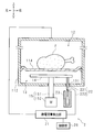
- FIG. 1 is a front view schematically showing an internal configuration of heating cooker 1 according to Embodiment 1 of the present invention.
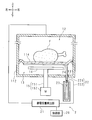
- FIG. 2 is a front view schematically showing the configuration of the state detection unit 2 included in the heating cooker 1.
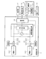
- FIG. 3 is a block diagram showing the configuration of the control system of the heating cooker 1.
- the heating cooker 1 of the present embodiment may be a single function type having only a microwave function, and has a multi-function having not only a microwave function but also an oven function, a grill function, and / or a toaster function. It may be a mold. Further, the oven function, the grill function, and the like may be any of an electric type and a gas type. Below, the microwave oven function of the heating cooker 1 is demonstrated.
- the heating cooker 1 includes a metal casing 11.
- the casing 11 includes an outer box 111 that constitutes an outer wall of the heating cooker 1, and an inner box 112 accommodated in the outer box 111.
- the space inside the outer box 111 and outside the inner box 112 is hereinafter referred to as an inner space 113.
- the heating cooker 1 is a so-called flat table type.
- a tray-like partition wall 114 that divides the inside of the inner box 112 in the vertical direction is disposed below the central portion in the vertical direction.
- the upper side of the partition 114 inside the inner box 112 is used as the heating chamber 12.
- a portion below the partition wall 114 in the inner box 112 is used as the antenna chamber 13. That is, of the wall portion of the inner box 112, the upper side from the partition wall 114 functions as the wall portion of the heating chamber 12, and the lower side from the partition wall 114 functions as the wall portion of the antenna chamber 13.
- the partition wall 114 functions as a wall portion that partitions the heating chamber 12 and the antenna chamber 13.
- the partition wall 114 is a bottom wall portion when viewed from the heating chamber 12, and the partition wall 114 is a top wall portion when viewed from the antenna chamber 13.
- the heating chamber 12 and the antenna chamber 13 are adjacent to each other through the partition wall 114.
- the inner box 112 has a function of shielding the microwave from leaking from the inside of the inner box 112 (that is, the heating chamber 12 and the antenna chamber 13) to the outside.
- the inner box 112 is grounded.
- the heating chamber 12 is provided with an open portion (not shown). The opening is closed so as to be opened and closed by a door (not shown) having a function of shielding microwaves. If the door is open, the user of the heating cooker 1 can put food F, which is an object to be heated, into and out of the heating chamber 12. That is, the heating chamber 12 accommodates the food F so that it can be collected and extracted.
- the outer box 111 is provided with an operation unit 17 having operation buttons or operation knobs operated by the user.
- the operation unit 17 includes an automatic cooking button to be operated when the user desires automatic cooking of the food F and a start button to be operated when the user desires to start cooking by heating. (Each not shown).
- the automatic cooking of the food F is, for example, automatic warming or automatic thawing of the food F.
- the partition 114 has heat resistance and non-conductivity.
- the partition 114 is made of, for example, ceramic.
- a circular through hole 131 is provided in the bottom wall portion of the antenna chamber 13.
- the inner diameter of the through hole 131 is shorter than the wavelength of the microwave so as to suppress leakage of the microwave through the through hole 131. Further, the inner diameter of the through hole 131 is longer than the outer diameter of the connection terminal 221 in order to smoothly insert and remove the connection terminal 221 described later. In practice, the inner diameter of the through hole 131 is 3 cm or less, preferably 5 mm or more and 10 mm or less.
- Inside the antenna chamber 13 is accommodated a disk-shaped rotary antenna 14 that is disposed facing the lower surface of the partition wall 114.
- the rotating antenna 14 is made of metal and is provided with one or a plurality of openings.
- the heating cooker 1 includes an antenna driving unit 15.
- the antenna drive unit 15 includes a rotation shaft unit 151 and a motor 152.
- the rotating shaft portion 151 passes through the bottom wall portion of the antenna chamber 13.
- the upper end portion of the rotating shaft portion 151 is attached to the center portion of the rotating antenna 14.
- the lower end portion of the rotation shaft portion 151 is connected to the output shaft of the motor 152.
- the motor 152 is accommodated in the internal space 113 below the antenna chamber 13.
- the motor 152 operates, the rotary shaft 151 rotates in conjunction with the motor 152 and the rotating antenna 14 rotates.
- the rotation shaft 151 stops rotating in conjunction with the motor 152 and the rotation of the rotating antenna 14 stops.
- the cooking device 1 includes a radio wave generator 16.
- the radio wave generator 16 is accommodated in the internal space 113 on the side of the inner box 112.
- the radio wave generator 16 has a magnetron (not shown) and generates a microwave. Microwaves generated by the radio wave generator 16 are guided into the antenna chamber 13 through a waveguide (not shown).
- the heating cooker 1 includes a state detection unit 2.
- the state detection unit 2 includes two electrode units, a control unit 20, a capacitance detection unit 21, a conductor 22, and an intermittent unit 23.
- One of the two electrode portions of the state detection unit 2 is constituted by a rotating antenna 14.
- the rotating antenna 14 is an electrode portion disposed on the lower side of the food F.
- the other of the two electrode portions of the state detection unit 2 is configured by an inner box 112 of the housing 11.
- the inner box 112 is an electrode part arranged on the upper side of the food F.
- the conductor 22 has a connection terminal 221 and a conductive wire 222.
- the conducting wire 222 is disposed in the internal space 113.
- One end of the conducting wire 222 is electrically connected to the capacitance detecting unit 21.
- the other end of the conducting wire 222 is electrically connected to the connection terminal 221.
- the connection terminal 221 has a circular bar shape in cross section.
- the outer diameter of the connection terminal 221 is shorter than the inner diameter of the through hole 131 of the antenna chamber 13.
- the base end portion of the connection terminal 221 is held by the intermittent portion 23 and is disposed in the internal space 113 below the antenna chamber 13.
- connection terminal 221 is inserted into and removed from the through hole 131 and advances and retreats with respect to the inside of the antenna chamber 13 through the through hole 131. Therefore, the tip of the connection terminal 221 may be positioned inside the antenna chamber 13 or may be positioned in the internal space 113 below the antenna chamber 13.
- the connection terminal 221 enters the inside of the antenna chamber 13, that is, when the distal end portion of the connection terminal 221 is located inside the antenna chamber 13, the distal end portion of the connection terminal 221 contacts the rotating antenna 14. .
- the rotating antenna 14 and the connection terminal 221 are electrically connected. In other words, at this time, the rotating antenna 14 and the capacitance detection unit 21 are electrically connected via the conductor 22.
- the opening is provided in the rotating antenna 14, it is necessary to prevent the connection terminal 221 from being inserted into the opening of the rotating antenna 14 by mistake.
- connection terminal 221 When the tip of the connection terminal 221 is separated from the rotary antenna 14, the electrical connection between the rotary antenna 14 and the connection terminal 221 is cut off. Therefore, when the connection terminal 221 is withdrawn from the inside of the antenna chamber 13, that is, when the distal end portion of the connection terminal 221 is located in the internal space 113 below the antenna chamber 13, the rotating antenna via the conductor 22. 14 and the electrostatic capacity detection unit 21 are disconnected from each other.
- the intermittent portion 23 holds the base end portion of the connection terminal 221 and moves the connection terminal 221 linearly in the length direction of the connection terminal 221.
- the intermittent portion 23 includes a biasing portion (for example, a spring) that biases the connection terminal 221 in the entry direction, and a suction portion (for example, a suction member) that counteracts the biasing force of the biasing portion and sucks the connection terminal 221 in the withdrawal direction. Solenoid).
- the connection terminal 221 urged in the approach direction by the intermittent portion 23 enters the inside of the antenna chamber 13 by being inserted into the through-hole 131 of the antenna chamber 13 and contacts the rotating antenna 14.
- the connection terminal 221 urged in the withdrawal direction by the intermittent portion 23 is withdrawn from the inside of the antenna chamber 13 by being extracted from the through hole 131 of the antenna chamber 13.
- the intermittent part 23 is not limited to the structure of this Embodiment.
- the intermittent portion 23 may have a configuration using a motor and a link or a cam that converts a rotational motion output from the motor into a reciprocating linear motion of the connection terminal 221.
- the capacitance detection unit 21 includes a detection circuit 211 and a high frequency voltage generation circuit 212.
- the capacitance detection unit 21 and the inner box 112 are electrically connected.
- the capacitance detection unit 21 and the rotary antenna 14 are electrically connected via a conductor 22.
- the capacitance detection unit 21 is electrically connected to the inner box 112 and the rotating antenna 14, when the high-frequency voltage generation circuit 212 generates a high-frequency voltage, a high-frequency signal is generated between the inner box 112 and the rotating antenna 14. A voltage is applied.
- the detection circuit 211 controls the operation of the high frequency voltage generation circuit 212.
- the detection circuit 211 also outputs a detection signal indicating a physical quantity corresponding to the capacitance between the inner box 112 and the rotating antenna 14 when a high-frequency voltage is applied between the inner box 112 and the rotating antenna 14. Output to the control unit 20.
- a change in capacitance between the inner box 112 and the rotating antenna 14 is detected as a change in impedance between the inner box 112 and the rotating antenna 14.
- the control unit 20 includes a CPU, a ROM, a RAM, and the like.
- the control unit 20 is given in advance a detection value of the capacitance when the food F is not stored in the heating chamber 12 as an initial value of the capacitance.
- the control unit 20 obtains a detected capacitance value of the food F based on the difference between the detected capacitance value indicated by the input detection signal and the initial value.
- the control unit 20 is preliminarily provided with a look-up table indicating the relationship between the detected capacitance value of the food F and the state of the food F (for example, the temperature of the food F).
- the control unit 20 obtains the state of the food F based on the input detection signal. That is, the state detection unit 2 indirectly detects the state of the food F based on the capacitance between the inner box 112 and the rotating antenna 14.
- the control unit 20 includes a detection signal input from the sensor,
- the state of the food F may be obtained by selectively using one or both of the detection signals input from the detection circuit 211.
- the control unit 20 is also a control center of the heating cooker 1.
- the control unit 20 controls operations of the antenna drive unit 15, the radio wave generation unit 16, the capacitance detection unit 21, and the intermittent unit 23.
- an operation signal indicating that the operation unit 17 has been operated is input to the control unit 20.
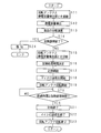
- FIG. 4 is a flowchart showing the procedure of the cooking process performed by the cooking device 1.
- the user opens the door of the heating cooker 1, places the food F on the partition wall 114, and then closes the door.
- the user operates the operation unit 17.
- a case where the user operates the start button after operating the automatic cooking button of the operation unit 17 is illustrated.
- the control unit 20 electrically connects the rotating antenna 14 and the capacitance detection unit 21 by controlling the operation of the intermittent unit 23 (S11). At this time, the connection terminal 221 enters the antenna chamber 13. Next, the control unit 20 controls the operation of the capacitance detection unit 21 to cause the capacitance detection unit 21 to detect the capacitance (S12). In the electrostatic capacitance detection unit 21 controlled by the control unit 20, the detection circuit 211 controls the operation of the high frequency voltage generation circuit 212 to generate a high frequency voltage. Next, the detection circuit 211 outputs a detection signal to the control unit 20. After outputting the detection signal, the detection circuit 211 ends the generation of the high frequency voltage by the high frequency voltage generation circuit 212.
- the control unit 20 performs state calculation processing for determining the state of the food F based on the detected capacitance value represented by the input detection signal (S13). Next, the control part 20 determines whether heat cooking is complete
- control unit 20 controls the operation of the intermittent unit 23 to disconnect the electrical connection between the rotating antenna 14 and the capacitance detecting unit 21. (S15). At this time, the connection terminal 221 exits from the inside of the antenna chamber 13.
- control part 20 determines the heat processing time which performs the heat processing of the food F by a microwave based on the result of the state calculation process of S13 (S16). Next, the control unit 20 resets the elapsed time measurement result to “0”, and then starts the elapsed time measurement (S17). The elapsed time may be measured using a timer (not shown) or by counting clocks used by the control unit 20.
- control unit 20 controls the operation of the radio wave generation unit 16 to start the generation of microwaves (S18), and controls the operation of the antenna drive unit 15 to start the rotation of the rotating antenna 14 (S19).
- S18 and S19 the microwave guided from the radio wave generator 16 into the antenna chamber 13 is scattered by the rotating rotating antenna 14.
- the microwave is uniformly irradiated to the food F. For this reason, the food F is heated uniformly.
- the control unit 20 determines whether or not the elapsed time is equal to or longer than the heat treatment time determined in S16 (S20). When the elapsed time is less than the heat treatment time (NO in S20), control unit 20 performs the process of S20 again. As a result, the food F continues to be heated by the action of the microwave until the heat treatment time determined in S16 elapses. When the elapsed time is equal to or longer than the heat treatment time (YES in S20), the control unit 20 finishes counting the elapsed time (S21). Further, the control unit 20 controls the operation of the radio wave generation unit 16 to end the generation of microwaves (S22), and controls the operation of the antenna drive unit 15 to stop the rotation of the rotating antenna 14 (S23). As a result of the processing of S22 and S23, the microwave irradiation to the food F is completed.
- control part 20 returns a process to S11. Thereafter, the state of the food F is indirectly detected again, and it is determined whether or not to end the cooking according to the detection result.
- finishing heat cooking it is YES at S14
- heat cooking is carried out.
- FIG. 5 is a characteristic diagram for explaining the effectiveness of the heating cooker 1. Whether the inventors can detect the capacitance of the food F stored in the heating chamber 12 even when the inner box 112 and the rotating antenna 14 are used as two electrode portions. In order to verify this, the following experiment was conducted. The inventors made the high-frequency voltage generation circuit 212 generate a high-frequency voltage of 200 kH, and first output a detection signal output from the capacitance detection unit 21 when nothing is accommodated in the heating chamber 12. Obtained. Next, a container having non-conductivity and heat resistance is accommodated in the heating chamber 12, and water having different weights (specifically, 100 g water and 200 g water) is accommodated in each container. The detection signal of the capacitance detection unit 21 according to the above was obtained. Moreover, the detection signal of the electrostatic capacitance detection part 21 concerning the case where only this container is accommodated in the heating chamber 12 (in other words, the case where 0 g of water is accommodated in this container) was obtained.
- the inventors then calculated the impedance change rate based on the obtained detection signal.
- the horizontal axis represents the weight (g) of water stored in the container
- the vertical axis represents the impedance change rate (%).
- the weight of the water stored in the container corresponds to the weight of the food F.
- the impedance change rate increases in proportion to the increase in the weight of the food F. As can be seen from this, even when the inner box 112 and the rotating antenna 14 are used as two electrode portions, the capacitance of the food F accommodated in the heating chamber 12 can be detected. .
- one of the two electrode portions of the state detection unit 2 is configured by the rotating antenna 14 and the other is the inner box 112 of the housing 11. It is composed.
- the rotating antenna 14 and the inner box 112 that are generally provided in the flat table type heating cooker 1 are used as the two electrode portions of the state detection unit 2. Therefore, it can suppress that the number of parts of the heating cooker 1 increases unnecessarily.
- the two electrode portions of the state detection unit 2 are not arranged in the heating chamber 12. Therefore, the heating chamber 12 is not unnecessarily narrowed due to the two electrode portions of the state detection unit 2. Therefore, there is no possibility of causing trouble in the food chamber F with respect to the heating chamber 12.
- the infrared sensor when detecting the state of the food F using an infrared sensor as described in Patent Document 1, the infrared sensor is arranged in the internal space 113.
- a through hole is provided in the wall portion of the heating chamber 12, and the infrared sensor detects the surface temperature of the food F through the through hole.
- the through hole provided in the wall portion of the heating chamber 12 impairs the sealing property of the heating chamber 12.
- the capacitance detection unit 21 it is not necessary to provide a through hole in the wall portion of the heating chamber 12. For this reason, the sealing property of the heating chamber 12 can be improved.
- the sealed heating chamber 12 can suppress leakage of microwaves and improve heat insulation.
- the rotating antenna 14 is not covered with an insulator.
- the rotating antenna 14 is accommodated in the antenna chamber 13, and the antenna chamber 13 is partitioned from the heating chamber 12 by the partition 114.
- inconvenience due to the rotating antenna 14 not being covered with an insulator for example, food hygiene problems caused by direct contact between the rotating antenna 14 and the food F, contamination of the rotating antenna 14, and short circuit
- the food F is placed on the partition 114 that partitions the antenna chamber 13 and the heating chamber 12 and covered with the inner box 112, and the rotating antenna 14 is disposed facing the partition 114. For this reason, the separation distance between the inner box 112 and the rotary antenna 14 and the food F does not become unnecessarily long. Therefore, the detection accuracy of the capacitance by the capacitance detector 21 is improved.
- the state detection unit 2 detects the capacitance by the capacitance detection unit 21 when the radio wave generation unit 16 does not generate the microwave, that is, when the microwave is not irradiated to the food F. Do. For this reason, the state detection unit 2 moves the connection terminal 221 of the conductor 22 to the inside of the antenna chamber 13 through the through hole 131 in the bottom wall portion of the antenna chamber 13 when the radio wave generation unit 16 does not generate microwaves.
- the rotary antenna 14 and the capacitance detection unit 21 are electrically connected via the conductor 22.
- the microwave leaks from the antenna chamber 13 to the internal space 113 and further to the outside of the heating cooker 1 through the conductor 22 electrically connected to the rotating antenna 14. As a result, there is a risk of malfunction, failure, or fire in the cooking device 1 or the electrical equipment around the cooking device 1.
- the state detector 2 detects the electrostatic capacitance by the electrostatic capacitance detector 21. Is not detected.
- the state detection unit 2 causes the connection terminal 221 of the conductor 22 to exit from the inside of the antenna chamber 13 through the through hole 131 in the wall of the antenna chamber 13 when the radio wave generation unit 16 does not generate microwaves. .
- microwave leakage through the conductor 22 does not occur.
- the inner diameter of the through hole 131 is sufficiently short, there is no possibility of leakage of microwaves through the through hole 131.
- the capacitance detection unit 21 cannot detect the capacitance.
- leakage of radio waves to the outside of the through hole 131 and the heating chamber 12 through the conductor 22 that electrically connects the internal electrode and the capacitance detection unit 21 is suppressed.
- the inner box 112 is always electrically connected to the capacitance detection unit 21.
- the rotating antenna 14 and the capacitance detection unit 21 depend on whether or not the radio wave generation unit 16 is generating microwaves and whether or not the capacitance detection unit 21 needs to detect capacitance. Can be appropriately connected / disconnected (that is, interrupted).
- the heating cooker 1 In the case of automatic cooking using the heating cooker 1, it is not necessary for the user to give the cooking time 1 or the weight of the food F to the cooking device 1. This is because the heating cooker 1 detects the state (specifically, temperature) of the food F at an appropriate timing, and heats the food F according to the detection result. Therefore, the convenience for the user is high.
- the heating cooker 1 of this Embodiment is a structure which heat-cooks using a microwave like a household microwave oven, it is not limited to this.
- the cooking device 1 may be configured such that cooking is performed using a high frequency having a wavelength longer than that of a microwave, such as a commercial food thawing machine.
- the state of the food F to be detected by the state detection unit 2 is not limited to the temperature of the food F, and may be, for example, the degree of baking or the degree of drying of the food F.
- the physical quantity that the state detection unit 2 should detect in order to obtain the state of the food F is not limited to capacitance or infrared rays, but may be weight or humidity.
- the state detection unit 2 may detect whether or not the food F has been heat denatured. At this time, it may be determined whether the food F has been heat-denatured based on a change in the capacitance of the food F.
- FIG. 6 is a front view schematically showing the configuration of the state detection unit 2 included in the heating cooker 1 according to Embodiment 2 of the present invention.
- FIG. 6 corresponds to FIG. 2 of the first embodiment.
- the configuration of the capacitance detection unit 21 and the capacitance detection procedure in the present embodiment are substantially the same as those in the first embodiment except that an electrode sheet 24 described later is used instead of the rotating antenna 14. That is, in the first embodiment, the two electrode portions of the state detection unit 2 are configured by the rotating antenna 14 and the inner box 112 of the housing 11, but in this embodiment, the electrode sheet 24 and the housing 11 inner boxes 112.
- the electrode sheet 24 is made of metal foil (for example, copper foil).
- the electrode sheet 24 is attached to the lower surface of the partition wall 114. That is, the electrode sheet 24 is an electrode portion disposed on the lower side of the food F.
- the electrode sheet 24 has a shape, a size, and a sticking position so that the microwave irradiation from the antenna chamber 13 to the heating chamber 12 is not hindered by the sticking of the electrode sheet 24 to the partition wall 114.
- a part of the antenna chamber 13 faces the through hole 131.
- the through-hole 131 of the antenna chamber 13 is arranged outside the rotation antenna 14 directly below.
- connection terminal 221 of this embodiment is longer than the connection terminal 221 of Embodiment 1.
- the tip of the connection terminal 221 that has entered the inside of the antenna chamber 13 contacts the electrode sheet 24.
- the electrode sheet 24 and the connection terminal 221 are electrically connected. That is, at this time, the electrode sheet 24 and the capacitance detection unit 21 are electrically connected via the conductor 22.
- the connection terminal 221 of the present embodiment is not electrically connected to the rotating antenna 14.
- the distance between the electrode sheet 24 and the food placed on the partition wall 114 is shorter than that of the rotating antenna 14. Therefore, compared with the heating cooker 1 of Embodiment 1, the detection accuracy of an electrostatic capacitance can be improved.
- FIG. 7 is a front view which shows typically the structure of the state detection part 2 with which the heating cooker 1 which concerns on Embodiment 3 of this invention is provided.
- FIG. 8 is a block diagram showing the configuration of the control system of the heating cooker 1. 7 corresponds to FIG. 6 of the second embodiment, and FIG. 7 corresponds to FIG. 3 of the first embodiment.
- the configuration of the capacitance detection unit 21 and the capacitance detection procedure in the present embodiment use the electrode sheets 241 and 242 instead of the rotating antenna 14 and the inner box 112, and each of the electrode sheets 241 and 242.
- it is substantially the same as in the first embodiment except that the connection terminals 221 and 221 contact and separate.
- Two through holes 132 and 133 are arranged in parallel on the bottom wall portion of the antenna chamber 13.
- Each of the through holes 132 and 133 has the same configuration as the through hole 131 of the first embodiment.
- the through holes 132 and 133 are arranged on both sides (left and right sides in FIG. 7) of the bottom wall portion of the antenna chamber 13 where the rotary shaft portion 151 passes, and on the outside of the rotary antenna 14.
- Each of the electrode sheets 241 and 242 is made of a metal foil (for example, a copper foil), and both are adhered to the lower surface of the partition wall 114.
- the electrode sheets 241 and 242 each have the same shape, size, and attachment position, without the microwave irradiation from the antenna chamber 13 to the heating chamber 12 being hindered by the attachment of the electrode sheets 241 and 242 to the partition wall 114.
- the electrode sheets 241 and 242 face the through holes 132 and 133 of the antenna chamber 13 in a one-to-one correspondence. That is, the electrode sheets 241 and 242 are electrode portions disposed on the lower side and the lateral sides of the food F (lower left side and lower right side in FIG. 7).
- the state detection unit 2 includes two conductors 22 and 22 and intermittent portions 23 and 23 in order to intermittently connect the capacitance detection unit 21 and the electrode sheets 241 and 242, respectively.
- the connection terminal 221 included in each conductor 22 is longer than the connection terminal 221 of the first embodiment.
- the connection terminals 221 and 221 advance and retreat with respect to the inside of the antenna chamber 13 as the control unit 20 controls the operation of the intermittent units 23 and 23.
- the front ends of the connection terminals 221 and 221 that have entered the antenna chamber 13 are in contact with the electrode sheets 241 and 242. At this time, the electrode sheets 241 and 242 and the connection terminals 221 and 221 are electrically connected. That is, at this time, the electrode sheets 241 and 242 and the capacitance detection unit 21 are electrically connected via the conductors 22 and 22.
- Each connection terminal 221 according to the present embodiment is not electrically connected to the rotating antenna 14 or the inner box 112.
- the electrical connection between the electrode sheets 241 and 242 and the connection terminals 221 and 221 is cut, and as a result, the conductor 22.
- the electrical connection between the electrode sheets 241 and 242 and the electrostatic capacitance detection unit 21 via is cut off.
- neither electrode sheet 241,242 is earth
- the electrode sheets 241 and 242 each have a shorter distance to the food placed on the partition wall 114 than both the rotating antenna 14 and the inner box 112. Therefore, compared with the heating cooker 1 of Embodiment 1, the detection accuracy of an electrostatic capacitance can be improved.
- FIG. 9 is a front view which shows typically the structure of the state detection part 2 with which the heating cooker 1 which concerns on Embodiment 4 of this invention is provided.
- FIG. 9 corresponds to FIG. 7 of the third embodiment.
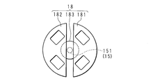
- FIG. 10 is a plan view schematically showing the configuration of the rotating antenna 18 provided in the heating cooker 1.
- the heating cooker 1 according to the present embodiment includes a rotating antenna 18 instead of the rotating antenna 14 according to the first embodiment.
- the rotating antenna 18 has a disk shape arranged facing the lower surface of the partition wall 114.
- the rotating antenna 18 has two antenna bodies 181 and 182 and a connecting portion 183.
- the connecting portion 183 is a non-conductive disk member, and is made of, for example, ceramic.
- the upper end portion of the rotating shaft portion 151 is attached to the central portion of the connecting portion 183.
- Each of the antenna main bodies 181 and 182 is a metal semi-disc member, and one or a plurality of openings are provided in each of the antenna main bodies 181 and 182.
- the antenna main bodies 181 and 182 are attached to the connecting portion 183 so that the chords of the semi-discs face each other and are separated by 180 ° in the circumferential direction of the connecting portion 183.
- the configuration of the capacitance detection unit 21 and the capacitance detection procedure in the present embodiment use the antenna main bodies 181 and 182 instead of the rotating antenna 14 and the inner box 112 and the antenna main bodies 181 and 182 respectively.
- it is substantially the same as in the first embodiment except that the connection terminals 221 and 221 contact and separate.
- Two through holes 134 and 135 are arranged in parallel on the bottom wall portion of the antenna chamber 13.
- Each of through holes 134 and 135 has the same configuration as through hole 131 of the first embodiment.
- the through holes 134 and 135 are arranged on both sides (left and right sides in FIG. 9) of the bottom wall portion of the antenna chamber 13 where the rotary shaft portion 151 passes, and directly below the rotary antenna 14.
- the state detection unit 2 includes two conductors 22 and 22 and intermittent portions 23 and 23 in order to intermittently connect the capacitance detection unit 21 and the antenna bodies 181 and 182, respectively.
- the connection terminal 221 included in each conductor 22 has the same length as the connection terminal 221 of the first embodiment.
- the connection terminals 221 and 221 advance and retreat with respect to the inside of the antenna chamber 13 as the control unit 20 controls the operation of the intermittent units 23 and 23.
- connection terminals 221 and 221 that have entered the antenna chamber 13 come into contact with the antenna bodies 181 and 182.
- each connection terminal 221 contacts one of the antenna bodies 181 and 182 and does not contact the other.
- both of the connection terminals 221 and 221 do not contact either one of the antenna main bodies 181 and 182.
- each connection terminal 221 of this embodiment does not contact the inner box 112.
- the antenna bodies 181 and 182 and the connection terminals 221 and 221 are electrically connected. That is, at this time, the antenna bodies 181 and 182 and the capacitance detection unit 21 are electrically connected via the conductors 22 and 22.
- the antenna main bodies 181 and 182 as described above are electrode portions arranged below the food F and on both sides in the lateral direction (lower left side and lower right side in FIG. 9).
- connection terminals 221 and 221 When the tip ends of the connection terminals 221 and 221 are separated from the antenna main bodies 181 and 182, the electrical connection between the antenna main bodies 181 and 182 and the connection terminals 221 and 221 is cut, and as a result, the conductor 22 The electrical connection between the antenna main bodies 181 and 182 and the electrostatic capacity detection unit 21 via is cut off. In the heating cooker 1 of the present embodiment, none of the antenna bodies 181 and 182 are grounded. Therefore, it is necessary to intermittently connect these and the capacitance detection unit 21 in order to suppress leakage of the microwave.
- the antenna bodies 181 and 182 each have a shorter distance to the food placed on the partition wall 114 than the inner box 112. Therefore, compared with the heating cooker 1 of Embodiment 1, the detection accuracy of an electrostatic capacitance can be improved.
- FIG. FIG. 11 is a perspective view showing a configuration of cooking aid 3 provided in heating cooker 100 (described later) according to Embodiment 5.
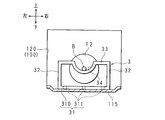
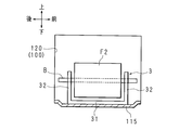
- 12 and 13 are a schematic front view and a side view for explaining how to use the cooking aid 3 when grilling food F1.
- FIG.12 and FIG.13 is also the front view and side view which show typically the internal structure of the heating chamber 120 with which the heating cooker 100 is provided.
- 14 and 15 are a schematic front view and side view for explaining how to use the cooking aid 3 when grilling food F2. 14 and 15 correspond to FIGS. 12 and 13.
- the heating cooker 100 includes a heating chamber 120.
- the bottom wall 115 of the heating chamber 120 has a tray shape.
- the cooking device 100 of the present embodiment may have a single function such as a microwave function, an oven function, a grill function, and a toaster function. It may have many functions. Further, the oven function, the grill function, and the like may be any of an electric type, a gas type, a steam type, and the like.
- the food F1 is, for example, bread or dried food.
- the food F2 is, for example, meat or fish.
- the skewer B is stabbed in the food F2. The skewer B penetrates the food F2, and both ends of the skewer B protrude from the food F2.
- Conventionally proposed cooking aids include a grid-like grill net, a corrugated plate, or a cooking net having leg portions protruding from a net body in which a plurality of rod-like portions are juxtaposed (for example, see JP 2010-197003 A, JP 2011-43267 A, and JP 2011-43277 A).
- the food F1 is cooked using these, the food F1 is placed on a grill net, a corrugated plate, or a net body of a cooking net, either directly or in a state of being placed on a bakeware.
- the food F2 is also cooked in the same manner as the food F1. That is, conventionally, the skewer B is not effectively used during cooking.
- the cooking assistance tool 3 of this Embodiment includes a net 31, four support legs 32, 32,... And two bowl-shaped portions 33, 33.
- the net 31 includes a rectangular frame 310 arranged in a horizontal posture and a plurality of rod-like portions 311, 311,... Arranged in a horizontal posture in the front-rear direction.
- the rectangular frame 310 has a longer left and right length than a front and rear length.
- the front-rear length and the left-right length of the rectangular frame 310 are shorter than the front-rear length and the left-right length of the bottom wall portion 115 of the heating chamber 120.
- Each rod-shaped part 311 is provided integrally between two long side parts of the rectangular frame 310.
- the net body 31 has a net shape in which rod-shaped portions 311, 311,... Are arranged in parallel in the left-right direction inside the rectangular frame 310.
- the net body 31 is not limited to the shape shown in FIG. 11, and may be, for example, a lattice net shape.
- the cooking assistance tool 3 may have, for example, a corrugated plate instead of the net body 31.
- each support leg 32 is integrally formed with the rectangular frame 310 of the net 31.
- Each hook-shaped portion 33 is arranged in a horizontal posture along the left-right direction. The hook-shaped portion 33 is integrally formed with the support legs 32, 32 so as to connect the other end portions (lower end portions in FIG. 11) of the support legs 32, 32 adjacent in the left-right direction.
- a plurality of locations (six locations in FIG. 11; only one location is shown in FIGS. 12 and 14) at the center in the left-right direction of the bowl-shaped portion 33 is the net body 31 side (upper side in FIGS. 11 and 12). Curved to the lower side.
- the concave side of each curved portion of the bowl-shaped portion 33 functions as a skewer receiving portion 34.
- the cooking assistance tool 3 as described above can be used in two ways, for example, for cooking with heat such as grilling and for cooking with cooking such as skewers, by placing it upside down. Specifically, when cooking the food F1 using the cooking aid 3, the user turns the net 31 upward and lowers the bowl-shaped portions 33, 33 as shown in FIGS. The cooking aid 3 is placed on the bottom wall 115 of the heating chamber 120 toward the side. At this time, the support legs 32, 32,... And the hook-shaped parts 33, 33 function as legs that support the net 31. The user places the food F1 on the net 31 and operates the heating cooker 100 to perform heating cooking. This is cooking such as grilling.
- the user faces the bowl-shaped portions 33 and 33 upward and the net 31 downward as shown in FIGS. Then, the cooking aid 3 is placed on the bottom wall 115 of the heating chamber 120. At this time, the net body 31 and the support legs 32, 32,... Function as leg parts that support the hook-shaped parts 33, 33.
- the user places one end portion and the other end portion of the skewer B on the pair of skewer receiving portions 34, 34. As a result, the skewer B is supported by the skewer receiving portions 34, 34 from below.
- the food F2 is pierced and supported by the grill skewer B.
- the user operates the cooking device 100 to perform cooking. This is cooking such as skewers.
- the cooking aid 3 is used regardless of whether the food F1 or the food F2 is cooked.
- the food F1 is in direct contact with the cooking aid 3, whereas the food F2 is not in contact with the cooking aid 3.
- the contamination of the cooking assistance tool 3 by contact with the food F2 is suppressed. Therefore, cleaning of the cooking assistance tool 3 after cooking is easy.
- the food F2 does not stick to the cooking aid 3. Therefore, damage to the food F2 due to sticking is prevented.
- the food F2 is not in contact with anything other than the skewer B. For this reason, food F2 is finished plumply.
- moisture or oil or the like that has exuded from the food F2 drops down to the bottom wall 115 of the heating chamber 120. Therefore, it is suppressed that the food texture of food F2 will be impaired by such moisture or fats and oils adhering to food F2. That is, the food F2 can be cooked satisfactorily by making effective use of the skewer B stuck to the food F2.
- the skewer B and the cooking assistance tool 3 should just have heat resistance.
- the grill skewer B is an iron skewer, and the cooking aid 3 is made of metal or ceramic.
- the skewer B and the cooking aid 3 need to have not only heat resistance but also non-conductivity.
- the grill skewer B is a bamboo skewer, and the cooking aid 3 is made of ceramic or heat-resistant plastic.
- the cooking aid 3 is not limited to the configuration of the present embodiment.
- the cooking aid 3 has a food placement portion on the top side on which food is to be placed, has a skewer receiving portion on the bottom side that receives the skewer that penetrates and supports the food, and is placed upside down. Any configuration can be used.
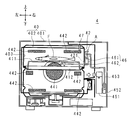
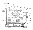
- FIG. FIG.16 and FIG.17 is the front view and side view which show typically the internal structure of the heating cooker 4 which concerns on Embodiment 6.
- FIG. The configuration of the heating cooker 4 in the present embodiment is substantially the same as the configuration of the heating cooker described in Japanese Patent No. 4994480 except for a configuration for attaching each steam generator A described later to the inner box 402. is there.
- the heating cooker 4 has a steam type oven function.
- Japanese Patent No. 4994480 exemplifies a multifunctional cooking device having a microwave oven function as well as a steam type oven function, but the cooking device 4 may be a multifunctional type or a single function type. Below, the steam type oven function of the heating cooker 4 is demonstrated.
- the heating cooker 4 includes a housing 40.
- the housing 40 includes an outer box 401 constituting the outer wall of the heating cooker 4 and an inner box 402 accommodated in the outer box 401. At least a part of the inside of the inner box 402 functions as a heating chamber 403.
- a tray 412 is accommodated in the heating chamber 403.
- a cooking assistance tool 411 is placed on the tray 412.
- the food F is placed on the cooking aid 411.
- the air supply port 422 is disposed on the front side and the lower side, the air outlets 421, 421,...
- An intake duct 431 is provided on the left front side of the inner box 402. One side of the intake duct 431 is connected to an opening (not shown) provided on the left wall of the outer box 401.
- An intake fan 432 is disposed in the opening. The other side of the intake duct 431 is connected to the air supply port 422.
- An exhaust duct 433 is provided on the right side of the inner box 402. One side of the exhaust duct 433 extends upward.
- An exhaust port 434 is provided at the extended end of the exhaust duct 433. The other side of the exhaust duct 433 is connected to the intake port 423. The air in the heating chamber 403 is taken into the exhaust duct 433 through the intake port 423 and discharged to the outside through the exhaust port 434.
- An intake port 441 is opened at the center of the rear wall of the inner box 402 in the vertical and horizontal directions.
- a plurality of jet outlets 442, 442,... Are opened at the peripheral edge of the rear wall of the inner box 402 so as to surround the air inlet 441.
- a circulation duct 440 is provided behind the inner box 402. One side of the circulation duct 440 is connected to the air inlet 441, and the other side of the circulation duct 440 is connected to the ejection ports 442, 442,.
- a circulation heater 443 and a circulation fan 444 are disposed inside the circulation duct 440.
- a fan motor 445 is connected to the circulation fan 444. When the fan motor 445 is operated, the air in the heating chamber 403 is sucked through the intake port 441 and heated by the circulation heater 443, and then returns to the heating chamber 403 through the ejection ports 442, 442,.
- the steam generator A generates steam to be supplied to the heating chamber 403.
- the steam generator A is attached to the outer surface of the right side wall portion 42 so as to cover the outlets 421, 421, ... from the outside of the inner box 402.
- a detachable water supply tank 451 is arranged on the left side of the steam generator A.
- the water supply tank 451 is connected to the water supply pipe 453 via the water supply pump 452.
- the water supply pipe 453 is connected to the steam generator A.
- the steam generator A includes a steam generation heater 46.
- the steam generating heater 46 When the steam generating heater 46 generates heat, the water supplied to the steam generator A evaporates.
- the steam generated at this time is supplied to the heating chamber 403 through the outlets 421, 421,.
- the food F is cooked by steam supplied to the heating chamber 403.
- a temperature sensor 47 that detects the temperature of the heating chamber 403 is disposed on the top wall of the inner box 402. Circulating heater 443 is controlled based on the temperature detected by temperature sensor 47. As a result, the temperature of the heating chamber 403 (and thus the temperature of air and water vapor circulating through the heating chamber 403 through the circulation duct 440) is maintained at a predetermined temperature.
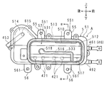
- the steam generator A includes a plate-shaped water heater 5 having a high thermal conductivity and a lid 6 that is long in the front-rear direction.
- the water heater 5 is arranged on the left side, and the lid 6 is arranged on the right side.
- the water heater 5 has a plate portion 51 that has a long rectangular shape in the front-rear direction.
- a first recess 511 is provided on the upper right side of the plate portion 51. The first recess 511 is long in the front-rear direction and is recessed on the left side (direction away from the lid body 6).
- a second recess 512 and an annular wall 513 are provided on the left surface of the plate portion 51.
- the second recess 512 is long in the front-rear direction and recessed on the right side.
- the annular wall 513 protrudes from the outer peripheral edge portion of the second recess 512.
- a long buffer chamber 52 is formed in the front-rear direction by the left surface of the plate portion 51 including the second recess 512 and the annular wall 513.
- a sealing member 531 is held at the tip of the annular wall 513. The sealing member 531 seals the gap between the tip of the annular wall 513 and the right side wall 42 of the inner box 402 by contacting the right side wall 42 of the inner box 402.
- a lead-out port 510 is provided in the upper part of the plate part 51.
- the lead-out port 510 penetrates the upper part of the plate portion 51 and forms an oval shape that is long in the front-rear direction.
- the first recess 511 and the second recess 512 communicate with each other through the outlet 510.
- An extension portion 514 is integrally provided at the rear portion of the plate portion 51.
- the extension part 514 extends upward in a tapered shape.
- the first recess 511 is formed across the extending portion 514. The opening of the first recess 511 is covered with the lid 6.
- an evaporating chamber 54 that is long in the front-rear direction is formed by the first recess 511 and the lid body 6 (more specifically, a third recess 612 to be described later).
- An annular groove 515 is provided on the peripheral edge of the right surface of the plate portion 51.
- a sealing member 532 is fitted and held in the annular groove 515. The sealing member 532 seals the gap between the plate portion 51 and the lid body 6.
- a steam generating heater 46 is embedded in the lower portion of the plate portion 51 by die casting.
- the steam generating heater 46 has a U shape that is long in the front-rear direction and has a rear portion curved in a semicircular shape, and includes a heat source 461 located on the upper side and a heat source 462 located on the lower side. Both the heat source 461 and the heat source 462 are disposed close to the buffer chamber 52. However, the heat source 461 is disposed close to the evaporation chamber 54, and the heat source 462 is spaced apart from the evaporation chamber 54.
- the heat source 461 is mainly used for the purpose of evaporating water.
- the heat source 462 is mainly used for the purpose of heating steam.
- the curved portion of the steam generating heater 46 is located below the extending portion 514.
- the heat generated by the steam generating heater 46 is conducted to the buffer chamber 52. Not only that, the heat of the heating chamber 403 is conducted to the buffer chamber 52 through the right side wall portion 42.
- a plate-shaped guide wall 516 is disposed at the center of the buffer chamber 52.
- the guide wall 516 protrudes from the left surface of the plate portion 51 toward the inner box 402.
- the guide wall 516 is long in the front-rear direction, and guides steam from the outlet port 510 in a direction intersecting the thickness direction of the plate portion 51 (a direction along the left surface of the plate portion 51).
- a sealing member 533 is held at the distal end portion of the guide wall 516.
- the sealing member 533 seals the gap between the leading end of the guide wall 516 and the right side wall 42 of the inner box 402 by contacting the right side wall 42 of the inner box 402. As a result, the passage of steam through the gap between the guide wall 516 and the right side wall portion 42 is suppressed.
- the end of the guide wall 516 on the outlet 510 side is bent downward and is in contact with the inner surface of the bottom wall of the annular wall 513.
- a reservoir portion 517 is formed between the portion bent downward of the guide wall 516 and the annular wall 513.
- a convex portion 518 protruding upward is provided at the end of the guide wall 516 opposite to the outlet 510. Since the water accumulated on the upper surface of the guide wall 516 is difficult to move over the convex portion 518, it easily flows down to the water reservoir 517.
- a vertical cross-sectional area between the guide wall 516 and the annular wall 513 (area of a cross section perpendicular to the flow direction of steam) is larger than the opening area of the outlet port 510. For this reason, the pressure of the steam led out from the outlet 510 to the buffer chamber 52 is reduced, and bumping is unlikely to occur in the reservoir 517.
- the space below the guide wall 516 in the buffer chamber 52 faces the outlets 421, 421,... Of the right side wall portion 42 of the inner box 402.
- the vertical cross-sectional area between the guide wall 516 and the annular wall 513 is wider than the total opening area of the plurality of outlets 421, 421,.
- On the upper part of the plate part 51 two attachment pieces 55, 55 that protrude upward are respectively provided integrally with being separated in the front-rear direction.
- Each attachment piece 55 has an insertion hole 551.
- two attachment pieces 56, 56 protruding downward are integrally provided separately in the front-rear direction.
- Each attachment piece 56 has an insertion hole 561.
- the front-rear mounting piece 56 is disposed in the front-rear direction of the air outlets 421, 421,..., And the rear-side mounting piece 56 is disposed in the front-rear direction. 421,... Behind the arrangement position in the front-rear direction.
- the lid body 6 includes a plate portion 61 having a rectangular shape that is long in the front-rear direction.
- the peripheral part of the plate part 61 is detachably attached to the peripheral part of the plate part 51 of the water heater 5 by a plurality of male screws (not shown).
- the plate portion 61 is provided with an outward convex portion 611 that protrudes to the right (in the direction away from the water heater 5).
- the inside of the outward convex part 611 becomes the 3rd recessed part 612 long in the front-back direction.
- An extension portion 613 is integrally provided at the rear portion of the plate portion 61.
- the extension part 613 extends upward in a tapered shape, and is disposed facing the extension part 514 of the plate part 51.
- An inward convex portion 614 is formed at the central portion excluding the peripheral edge portion of the extending portion 613.
- the inward convex portion 614 has a circular recess on the outer surface, and the tip is disposed to face the right surface of the extension portion 514.
- a water supply port 615 is opened at the center of the inward convex portion 614.
- the water supply port 615 is a position separated rearward from the outlet port 510 and is disposed at substantially the same position as the outlet port 510 in the vertical direction.
- a water supply pipe 453 is connected to the water supply port 615.
- the water supplied through the water supply port 615 first flows into the evaporation chamber 54.
- steam is generated in the evaporation chamber 54 by the heat generated by the heat source 461.
- the lower surface of the third recess 612 in other words, the lower surface of the evaporation chamber 54 is inclined such that the outlet 510 side is high and the water supply port 615 side is low. For this reason, even if the supplied water flows down to the lower surface of the evaporation chamber 54, it evaporates on the side away from the outlet 510.
- the vapor generated in the evaporation chamber 54 is led out to the buffer chamber 52 through the outlet 510.
- the steam led out to the buffer chamber 52 is guided along the guide wall 516 to the outlets 421, 421,. At this time, the steam does not move linearly from the outlet 510 to the outlets 421, 421,. For this reason, the heat generated by the steam generating heater 46 is sufficiently conducted to the steam in the buffer chamber 52.
- the vertical cross-sectional area between the guide wall 516 and the annular wall 513 is larger than the total opening area of the plurality of outlets 421, 421,. To rise. Therefore, the steam smoothly flows in the buffer chamber 52. Therefore, the pressure increase in the buffer chamber 52 is suppressed.
- FIG. 21 is a front view schematically showing a configuration of a steam generator B included in a conventional cooking device.
- FIG. 21 corresponds to FIG. 22 is a cross-sectional view taken along the line ⁇ - ⁇ in FIG.
- FIG. 22 corresponds to FIG.
- the difference between the steam generators A and B is that the steam generator A includes the mounting pieces 56 and 56, but the steam generator B does not include these, and the steam generator B dissipates heat as described below. However, the steam generator A does not include these parts.
- the heat dissipating parts 519, 519,... are formed in a cylindrical shape protruding from the left surface of the plate part 51, and female screws are formed inside.
- Each of the heat dissipating parts 519 is provided integrally with the plate part 51, and includes heat dissipating parts 519, 519,... Between the left and right sides of the guide wall 516 in the buffer chamber 52, Arranged in between.
- each heat radiating part 519 is screwed to the right side wall part 42 from the heating chamber 403 side through a through hole (not shown) provided in the right side wall part 42.
- the steam contact area in the water heater 5 is increased by the presence of the heat radiating parts 519, 519,.
- the heat dissipating parts 519, 519,... Have a drawback that the steam flow velocity is reduced because the frictional resistance against the steam increases as the contact area of the steam increases.
- the gap between the steam generator B and the right side wall portion 42 of the inner box 402 has a sealing member 531 held at the tip portion of the annular wall 513 and a sealing member held at the tip portion of the guide wall 516. 533 is sealed, but if the pressure in the buffer chamber 52 rises excessively, the right side wall portion 42 of the inner box 402 bends, and the sealing members 531 and 533 and the right side wall portion 42 of the inner box 402 A void is formed between the two.
- the steam generator B does not include the heat radiating portions 519, 519,.
- various problems caused by the heat radiation portions 519, 519,... Do not occur.
- the heat radiating portions 519, 519,... also have a role of fixedly attaching the lower portion of the steam generator B to the right side wall portion 42 of the inner box 402 by screwing using the female screws of the heat radiating portions 519, 519,. is there. Therefore, the steam generator B without the heat radiation portions 519, 519,... Is bolted using the fitting holes 551, 551 of the mounting pieces 55, 55 so that the upper portion of the steam generator B is the right side wall portion 42 of the inner box 402. It is only attached to.
- the steam generator A does not include the heat radiating portions 519, 519,. For this reason, the various problems resulting from the thermal radiation part 519,519, ... do not arise.
- the upper part of the steam generator A is attached to the right side wall portion 42 of the inner box 402 by bolting using the fitting holes 551, 551 of the attachment pieces 55, 55.
- the lower part of the steam generator A is attached to the right side wall portion 42 of the inner box 402 by bolting using the fitting holes 561 and 561 of the pieces 56 and 56.
- the upper and lower portions of the steam generator A are not simply attached to the right side wall portion 42 of the inner box 402.
- Each of the attachment pieces 55, 55, 56, 56 is disposed outside the buffer chamber 52 and in a portion corresponding to a space other than the high-speed space where the vapor flow rate in the buffer chamber 52 is highest.
- the high-speed space is a space in a range where the air outlets 421, 421,. For this reason, the bending of the right side wall part 42 and the floating of the steam generator A can be suppressed efficiently. This is because the high-speed space has a lower pressure than the space where the flow velocity is lower than that of the high-speed space. Even if the portion corresponding to the high-speed space in the steam generator A is attached to the right side wall portion 42 of the inner box 402, the deflection of the right side wall portion 42 and the lifting of the steam generator A cannot be efficiently suppressed.
- the steam generator A is not limited to the present embodiment.
- a plurality of attachment portions for attaching the steam generator A to the right side wall portion 42 of the box 402 are provided outside the flow space through which the steam flows, such as the buffer chamber 52 and the evaporation chamber 54. What is necessary is just to be arrange
- a portion where the flow direction of steam for example, the vicinity of a corner portion of the annular wall 513
- a portion where steam does not easily flow for example, the vicinity of the water storage portion 517, or the like can be considered.
- FIG. 23 and 24 are front views schematically showing the internal configuration of the heating cooker 7 according to the seventh embodiment.
- FIG. 23 shows a case where food F3 is cooked using each rotating container 8 described later
- FIG. 24 shows a case where food F4 is cooked using a cooking aid 712 described later.
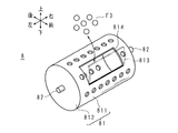
- 25 and 26 are a perspective view and a cross-sectional view schematically showing the structure of the rotating container 8 provided in the cooking device 7.
- the heating cooker 7 in the present embodiment has at least a steam type oven function.
- the cooking device 7 may be a multi-function type or a single-function type. Below, the steam type oven function of the heating cooker 7 is demonstrated.
- the cooking device 7 includes a casing 70.
- the housing 70 includes an outer box 701 constituting the outer wall of the heating cooker 7 and an inner box 702 accommodated in the outer box 701. At least a part of the inside of the inner box 702 functions as a heating chamber 703.
- a first jet port 721 including one or a plurality of openings is provided in the top wall portion 704 constituting the wall portion of the heating chamber 703. Further, in the inner box 702, a second jet port 722 including one or a plurality of openings is provided at the center in the vertical direction of the left side wall 705 constituting the wall of the heating chamber 703. Further, in the inner box 702, a suction port 723 including one or a plurality of openings is opened at the upper portion of the right side wall portion 706 constituting the wall portion of the heating chamber 703.
- a through hole is provided in each of the left and right side wall portions 705 and 706 of the heating chamber 703 in the center in the up-and-down front and rear direction, and one bearing 707 is disposed in each through hole.
- the bearing 707 of the left side wall portion 705 and the bearing 707 of the right side wall portion 706 are arranged at the same position in the vertical direction.
- a circulation duct 72 is provided along the top wall 704 and the left and right side walls.
- the upstream end of the circulation duct 72 is connected to the suction port 723, and the downstream end is connected to the second jet port 722.
- a central portion in the ventilation direction of the circulation duct 72 is connected to the first jet outlet 721.
- Bearings 727 and 727 arranged to face the bearings 707 and 707 are attached to portions of the wall portion of the circulation duct 72 that are disposed to face the left wall portion 705 and the right wall portion 706.
- the space inside the outer box 701 and outside the inner box 702 and the circulation duct 72 is hereinafter referred to as an inner space 708.
- a circulation heater 724 and a circulation fan 725 are disposed inside the circulation duct 72.
- the circulation heater 724 is disposed so as to face the opening portion of the first jet outlet 721 in the top wall 704 of the inner box 702.
- the circulation fan 725 is disposed opposite to the opening portion of the suction port 723 in the right side wall 706 of the inner box 702.
- the circulation fan 725 passes through the wall portion of the circulation duct 72 and is connected to a fan motor 726 disposed in the internal space 708.
- a steam generator 731 that generates steam to be supplied to the heating chamber 703 and a detachable water supply tank 732 that stores water to be supplied to the heating chamber 703 are arranged.
- the water stored in the water supply tank 732 is supplied to the steam generator 731 by a water supply pump (not shown).
- the steam generator 731 heats the supplied water by a steam generating heater (not shown). The steam generated at this time is supplied to the heating chamber 703.
- the heating cooker 7 includes an opening / closing part 74.
- the opening / closing part 74 closes the second ejection port 722 so that it can be opened and closed.
- ventilation through the second ejection port 722 between the heating chamber 703 and the circulation duct 72 is blocked.
- the opening / closing part 74 guides ventilation through the second ejection port 722 between the heating chamber 703 and the circulation duct 72.
- Such an opening / closing portion 74 has, for example, a hinge lid shape, and the opening / closing axis of the hinge lid is disposed below the second jet port 722 in the left side wall portion 705 of the inner box 702.
- the lid body of the hinge lid closes the second jet port 722.
- the lid body of the hinge lid is arranged in an inclined posture inside the circulation duct 72, thereby smoothly guiding the air flowing through the circulation duct 72 to the second jet outlet 722. To do.
- a tray 711 is accommodated in the heating chamber 703.
- the rotating container 8 is detachably accommodated above the tray 711 in the heating chamber 703 (see FIG. 23)
- the cooking aid 712 is detachably placed on the tray 711. In some cases (see FIG. 24).
- the food F3 is accommodated in the rotating container 8.
- the food F4 is placed on the cooking aid 712.
- the rotating container 8 has a container body 81 and rotating shafts 82 and 82.
- the container main body 81 has a cylindrical peripheral surface portion 811 in which a plurality of through holes are formed, and end surface portions 812 and 812 that close both end openings of the cylinder.
- a rotation shaft 82 projects from the center of each end surface portion 812 toward the outside.
- An opening 814 is provided in the peripheral surface portion 811, and the opening 814 is closed by a lid 813 so as to be opened and closed.
- the lid 813 has a hinge lid shape, for example.
- the lid 813 has a plurality of through holes.
- the lid 813 functions as a part of the peripheral surface portion 811 when the opening 814 of the peripheral surface portion 811 is closed. When the lid 813 is opened, the food F3 can be taken in and out of the container body 81 through the opening 814 of the peripheral surface portion 811.
- the rotating container 8 of the present embodiment is made of metal, and the peripheral surface portion 811 is made of punching metal in which a through hole having a diameter of about 3 mm is formed, but is not limited thereto.
- the rotary container 8 may be configured using a non-metal.
- the peripheral surface portion 811 is not limited to the configuration of the present embodiment as long as the opening ratio is high and the food F3 accommodated in the container body 81 does not fall off, and has a net shape or a bowl shape. May be.
- the shape of the rotating container 8 may be any shape as long as the rotating container 8 can rotate and the food F3 contained in the container body 81 can be easily stirred by the rotation of the rotating container 8.
- the heating cooker 7 includes rotation support shafts 831 and 831, a drive gear 832, a driven gear 833, and a rotation motor 834.
- the rotary motor 834 is disposed in the internal space 708, but the output shaft of the rotary motor 834 extends to the inside of the circulation duct 72.
- the rotation support shafts 831 and 831 are arranged in a horizontal posture along the left-right direction. A center portion in the axial direction of each rotation support shaft 831 is rotatably supported by a bearing 707. The left end (or right end) of the left (or right) rotation support shaft 831 is rotatably supported by a bearing 727.
- the drive gear 832 and the driven gear 833 are disposed inside the circulation duct 72.
- the right rotation support portion 831 is provided with a driven gear 833.
- a drive gear 832 is engaged with the driven gear 833.
- the drive gear 832 is connected to the output shaft of the rotary motor 834.
- the left rotation support shaft 831 has a rotation shaft attachment portion 835 at the right end, and the right rotation support shaft 831 has a rotation shaft attachment portion 835 at the left end.
- a rotation shaft attachment portion 835 of each rotation support shaft 831 protrudes into the heating chamber 703.
- the rotating shafts 82 and 82 of the rotating container 8 are detachably attached to the rotating shaft attaching portion 835 of each rotating support shaft 831.
- the container main body 81 When the rotation shafts 82 and 82 are attached to the rotation support shafts 831 and 831, the container main body 81 is rotatably arranged at the central portion in the vertical and forward / rearward directions of the heating chamber 703 in a lateral posture with the axial length direction along the horizontal direction. Furthermore, the upper part of the peripheral surface portion 811 of the container main body 81 is disposed so as to face the first ejection port 721.
- the rotation motor 834 When the rotation motor 834 is operated, the rotation motion output from the rotation motor 834 is transmitted to the right rotation shaft 82 via the drive gear 832, the driven gear 833, and the right rotation support shaft 831. As a result, the rotating container 8 rotates. As the rotating container 8 rotates, the food F3 accommodated in the container body 81 is agitated. When the rotating container 8 is accommodated in the heating chamber 703, the opening / closing part 74 is closed. On the other hand, when the rotating container 8 is not accommodated in the heating chamber 703, the opening / closing part 74 is opened.
- the opening / closing of the opening / closing part 74 may be linked to the attachment / detachment of the rotation shafts 82, 82 with respect to the rotation support shafts 831, 831.
- the opening / closing portion 74 may be configured to be switched automatically or manually when a user operates an operation portion (not shown).
- the food F3 is coffee beans, fried rice, fried noodles or the like. Now, it may be desired to stir the food F3 when cooking the food F3. This is the case, for example, when roasting coffee beans or fried fried rice or fried noodles.
- the conventional cooking device having a steam oven function does not have a function of stirring the food F3.
- the heating cooker 7 rotates the rotating container 8 and circulates steam at a predetermined temperature. At this time, since the second ejection port 722 is closed, the flow velocity of the steam ejected from the first ejection port 721 increases.
- the peripheral surface portion 811 of the rotating container 8 has a high opening ratio to such an extent that the food F3 accommodated in the container body 81 does not fall off from the container body 81. Accordingly, the steam efficiently enters and exits the container body 81 through the through-hole formed in the peripheral surface portion 811. As a result, the food F3 can be cooked uniformly while stirring.
- the coffee beans can be roasted by cooking the coffee beans using steam.
- the agitation of the coffee beans has the effect of uniform roasting of the coffee beans, and the coffee bean shells are broken and broken by the collision of the coffee beans, and the trays are passed through the through holes formed in the peripheral surface portion 811.
- the effect of falling to 711 is also achieved.
- the food F3 is cooked in a low oxygen state as compared with other types of cooking. Therefore, the oxidation of food F3 can be suppressed. If the food F3 is oxidized, the taste or quality of the food F3 may be deteriorated.
- the cooking device 7 places the cooking aid 712 on the tray 711 and places the food F4 on the cooking aid 712.
- the second spout 722 is opened, steam ejected from the first spout 721 and the second spout 722, that is, steam ejected from the upper side and the left side of the food F4 toward the food F3.
- the food F4 can be cooked efficiently.
- FIG. 27 is a front view schematically showing the internal configuration of the heating cooker 7 according to the eighth embodiment.
- FIG. 28 is a cross-sectional view schematically showing the structure of the rotating container provided in the heating cooker 7. 27 and 28 correspond to FIGS. 23 and 26 of the seventh embodiment.
- the heating cooker 7 according to the present embodiment has substantially the same configuration as the heating cooker 7 according to the seventh embodiment.
- differences from the seventh embodiment will be described, and other parts corresponding to those of the first embodiment are denoted by the same reference numerals, and description thereof will be omitted.
- the rotating container 8 of the present embodiment has a rotating shaft 84 instead of the rotating shafts 82 and 82 of the seventh embodiment.
- the rotating shaft 84 has a cylindrical shape.
- the rotation shaft 84 passes through the center of each of the end surface portions 812 and 812 of the container main body 81.
- the left end portion 841 and the right end portion 842 of the rotation shaft 84 protrude outward from the end surface portions 812 and 812.
- the left end portion 841 is detachably attached to a rotation shaft attachment portion 837 of a rotation support shaft 836 described later.
- the right end 842 is detachably attached to the rotation shaft attachment portion 835 of the rotation support shaft 831.
- a central portion 843 in the left-right direction of the rotation shaft 84 is disposed from one end surface portion 812 to the other end surface portion 812 inside the container body 81.
- a plurality of through holes are provided on the peripheral surface of the central portion 843.
- the heating cooker 7 includes a rotation support shaft 836 instead of the left rotation support shaft 831 of the seventh embodiment.
- a cylindrical rotation shaft mounting portion 837 is provided at the right end portion of the rotation support shaft 836.
- the rotation support shaft 836 has a bottomed cylindrical shape, and the rotation shaft attachment portion 837 is disposed on the opening side of the bottomed cylinder.
- a plurality of through holes are provided on the peripheral surface of the rotation support shaft 836.
- the cooking device 7 rotates the rotating container 8 and circulates steam at a predetermined temperature.
- steam flows into the rotation support shaft 836 through a through hole provided in the left rotation support shaft 836, and from here the rotation shaft attachment portion 837 passes through the rotation shaft.
- Steam flows into the interior of 84, and the steam is ejected into the container body 81 of the rotating container 8 through a through hole provided in the rotating shaft 84. Further, the steam efficiently enters and exits the container body 81 through the through-hole formed in the peripheral surface portion 811 of the container body 81. As a result, the food F3 can be cooked uniformly while stirring.
- the heating cooker 7 as described above can spray steam onto the food F3 accommodated in the rotating container 8 more directly than the heating cooker 7 of the seventh embodiment.
- the structure is complicated because the central portion 843 of the rotating shaft 84 is arranged inside the container main body 81, it is difficult to clean the inside of the container main body 81.
- a heating cooker 1 accommodates a heating chamber 12 that accommodates food F, a rotating antenna 14 for radiating radio waves to the food F accommodated in the heating chamber 12, and the rotating antenna 14. And an antenna chamber 13 that is separated from the heating chamber 12 and is adjacent to the heating chamber 12, and a state detection unit 2 that detects the state of the food F, according to the detection result of the state detection unit 2.
- the state detection unit 2 is arranged outside the heating chamber 12, and at least one of the two electrodes arranged inside the antenna chamber 13 And a capacitance detection unit 21 that detects a capacitance between the two electrode units.
- the inner box 11 has conductivity, the inner box 11 constitutes the other electrode part, and the rotating antenna 14 constitutes the one electrode part. It is characterized by being.
- the capacitance detection unit 21 is disposed outside the antenna chamber 13, and a through hole 131 is provided in a wall portion of the antenna chamber 13, and the antenna chamber In order to intermittently connect the electrode portion disposed inside 13 and the capacitance detecting portion 21, one side can be moved forward and backward with respect to the inside of the antenna chamber 13 through the through hole 131. It further includes a conductor 22 that is electrically connected to the electrode portion inside and is electrically connected to the capacitance detecting portion 21 on the other side.
- the cooking device 1 according to the present invention is configured to irradiate the radio wave intermittently, and the state detection unit 2 is configured such that when the radio wave is not irradiated, the electrostatic capacitance is detected by the capacitance detection unit 21. This is characterized in that detection of the above is performed.
- the cooking device is a so-called flat table type cooking device. Since the flat table type cooking device does not include a turntable, the object to be heated accommodated in the heating chamber is uniformly irradiated with radio waves by rotating the rotating antenna.
- the rotating antenna is accommodated in an antenna chamber adjacent to the heating chamber. Both of the two electrode portions of the state detection unit are arranged outside the heating chamber. For this reason, the heating chamber is not unnecessarily narrowed.
- the two electrode parts of the state detection part at least one of the electrode parts is arranged inside the antenna room. Since the antenna chamber is separated from the heating chamber, inconveniences (for example, food hygiene problems, internal electrode contamination, and short-circuiting) due to the electrode portion (that is, the internal electrode portion) not being covered with an insulator. Etc.) does not occur. Therefore, the internal electrode portion does not need to be covered with an insulator.
- the separation distance between the internal electrode portion and the object to be heated does not become unnecessarily long. Therefore, the capacitance detection accuracy is improved.
- the wall section that divides the antenna chamber and the heating chamber constitutes a flat table
- the object to be heated is placed on the flat table, and therefore the separation distance between the internal electrode section and the object to be heated is small. Minimized.
- the rotating antenna constitutes one electrode part. Since the rotating antenna has conductivity, it can be used as one electrode part. Further, the wall portion of the heating chamber constitutes the other electrode portion. Generally, since the wall part of a heating chamber has electroconductivity, this can be utilized as the other electrode part. As a result, it is possible to suppress an unnecessary increase in the number of parts of the heating cooker.
- the rotating antenna and the wall of the heating chamber and the object to be heated are kept in non-contact. Since the rotating antenna is arranged inside the antenna chamber adjacent to the heating chamber, the separation distance from the object to be heated does not become unnecessarily long. Further, the separation distance between the wall of the heating chamber and the object to be heated does not become unnecessarily long. Therefore, the capacitance detection accuracy is improved.
- the radio waves when radio waves are applied to the object to be heated accommodated in the heating chamber, the radio waves pass through the inside of the antenna chamber. Since the capacitance detection unit is arranged outside the antenna room, it is possible to prevent the capacitance detection unit from causing malfunction or failure due to radio waves passing through the antenna room.
- a through hole is provided in the wall of the antenna chamber. However, if the inner diameter of the through hole is set to be appropriately short, it is possible to suppress unnecessary leakage of radio waves from the inside of the antenna chamber to the outside of the heating chamber through the through hole.
- the internal electrode and the capacitance detector are electrically connected via the conductor.
- the capacitance can be detected by the capacitance detector.
- the conductor exits outside the antenna chamber through the through hole in the antenna chamber wall the electrical connection between the internal electrode portion and the capacitance detector via the conductor is cut. At this time, the capacitance cannot be detected by the capacitance detector.
- unnecessary leakage of radio waves to the outside of the antenna chamber and the heating chamber is suppressed through a conductor that electrically connects the internal electrode and the capacitance detection unit.
- the internal electrode unit and the capacitance detection unit can be appropriately interrupted according to the necessity of detection of the capacitance by the capacitance detection unit. If radio waves leak to the outside of the antenna room and the heating chamber, it may cause malfunction or failure of the cooking device or electric devices around the cooking device.
- the state detection unit detects the capacitance by the capacitance detection unit when the object to be heated contained in the heating chamber is not irradiated with radio waves. If it is attempted to detect the capacitance while the object to be heated is irradiated with radio waves, the detection accuracy of the capacitance deteriorates due to radio wave interference.
- the time zone in which radio waves are irradiated and the time zone in which no radio waves are irradiated are alternately repeated. Therefore, if the time zone in which no radio wave is irradiated is effectively used, the capacitance can be efficiently detected by the capacitance detector.
- the electrostatic capacity can be determined at any time during the cooking by the oven function or the grill function. Capacitance can be detected by the detection unit.
- the cooking device 1 may include components that are not disclosed in the first to eighth embodiments.
- the constituent elements (technical features) disclosed in each embodiment can be combined with each other, and a new technical feature can be formed by the combination.
- Heating cooker 112 Inner box (wall part of heating chamber, electrode part) 12 Heating chamber 13 Antenna chamber 131 Through hole 14 Rotating antenna (electrode part) 2 State detector 21 Capacitance detector 22 Conductor F Food (object to be heated)
Landscapes
- Physics & Mathematics (AREA)
- Electromagnetism (AREA)
- Electric Ovens (AREA)
- Constitution Of High-Frequency Heating (AREA)
- Control Of High-Frequency Heating Circuits (AREA)
Abstract
加熱室に配された電極部によって加熱室が狭まることなく、静電容量の検出結果に応じて被加熱物を加熱調理することができる加熱調理器を提供する。 加熱調理器1の状態検出部2が有する電極部(具体的に内箱112及び回転アンテナ14)は、加熱室12の外部に配されている。故に、加熱室12が無用に狭まることはない。また、アンテナ室13の内部に配されている電極部と食品Fとは、加熱室12とアンテナ室13とを区画する壁部によって非接触に保たれる。加熱室12とアンテナ室13とは隣接しているため、電極部と食品Fとの離隔距離が無用に長くなることはない。従って、静電容量の検出精度が向上する。
Description
本発明は、電波を用いて被加熱物を加熱調理する加熱調理器に関する。
電子レンジ機能を有する加熱調理器は、加熱室を備えている。加熱室には、被加熱物である食品が収脱可能に収容される(特許文献1参照)。
特許文献1には、食品の加熱調理中に赤外線センサを用いて食品の温度を非接触で検出し、検出結果に基づいて加熱調理を終了させるか否かを判定することが記載されている。
特許文献1には、食品の加熱調理中に赤外線センサを用いて食品の温度を非接触で検出し、検出結果に基づいて加熱調理を終了させるか否かを判定することが記載されている。
ところで、食品の温度と食品の静電容量とは相関関係にある。このため、食品の静電容量に基づいて食品の温度を測定する非接触型品温測定装置が提案されている(特許文献2参照)。
特許文献2に記載の非接触型品温測定装置は、一対の電極を備えている。食品は、一対の電極間に非接触で配置される。食品の温度は、一対の電極間に高周波電圧が印加されたときに検出される静電容量に基づいて求められる。
特許文献2に記載の非接触型品温測定装置は、一対の電極を備えている。食品は、一対の電極間に非接触で配置される。食品の温度は、一対の電極間に高周波電圧が印加されたときに検出される静電容量に基づいて求められる。
特許文献2に記載の非接触型品温測定装置の場合、各電極は実質的な絶縁体で被覆されている。食品は、絶縁体を介して、電極上に載置される。何故ならば、食品衛生、短絡防止、電極の汚損防止、及び高精度の測定等のためには、電極が食品に接触せず、且つ、電極と食品との離隔距離が短い方が好ましいからである。
故に、特許文献2に記載の非接触型品温測定装置を、電子レンジ機能を有する加熱調理器に単純に適用した場合、絶縁体で被覆された電極が加熱室に配置される。すると、加熱室が狭くなって、食品の収脱に支障を来す虞がある。
故に、特許文献2に記載の非接触型品温測定装置を、電子レンジ機能を有する加熱調理器に単純に適用した場合、絶縁体で被覆された電極が加熱室に配置される。すると、加熱室が狭くなって、食品の収脱に支障を来す虞がある。
本発明は斯かる事情に鑑みてなされたものであり、その主たる目的は、加熱室を狭めることなく、静電容量の検出結果に応じて被加熱物を加熱調理することができる加熱調理器を提供することにある。
本発明に係る加熱調理器は、被加熱物を収容する加熱室と、該加熱室に収容されている被加熱物へ電波を照射するための回転アンテナと、該回転アンテナを収容しており、前記加熱室とは区画されて該加熱室に隣接するアンテナ室と、前記被加熱物の状態を検出する状態検出部とを備え、該状態検出部の検出結果に応じて、前記被加熱物を加熱調理する加熱調理器において、前記状態検出部は、前記加熱室の外部に配され、少なくとも一方は前記アンテナ室の内部に配されている2個の電極部と、該2個の電極部の間の静電容量を検出する静電容量検出部とを有することを特徴とする。
本発明に係る加熱調理器は、前記加熱室の壁部は導電性を有し、前記壁部が他方の電極部を構成しており、前記回転アンテナは前記一方の電極部を構成していることを特徴とする。
本発明に係る加熱調理器は、前記静電容量検出部は前記アンテナ室の外部に配されており、前記アンテナ室の壁部には貫通孔が設けてあり、前記アンテナ室の内部に配されている電極部と前記静電容量検出部とを断続すべく、一側が前記貫通孔を通して前記アンテナ室の内部に対し進退可能にしてあり、前記アンテナ室の内部にて前記電極部に電気的に接続され、他側が前記静電容量検出部に電気的に接続されている導体を更に備えることを特徴とする。
本発明に係る加熱調理器は、前記電波を断続的に照射するようにしてあり、前記状態検出部は、前記電波が照射されていない場合に前記静電容量検出部による静電容量の検出を行なうようにしてあることを特徴とする。
本発明の加熱調理器による場合、2個の電極部は加熱室の外部に配される。故に、2個の電極部を加熱室に配置したせいで加熱室が無用に狭まることを防止することができる。
また、少なくとも一方の電極部はアンテナ室の内部に配置される。
しかも、アンテナ室は加熱室とは区画されている。従って、アンテナ室の内部に配されている電極部(以下、内部電極部という)が絶縁体で被覆されていないとしても、非接触で静電容量を検出することができる上に、短絡及び電極の汚損等の発生を抑制することができる。
また、少なくとも一方の電極部はアンテナ室の内部に配置される。
しかも、アンテナ室は加熱室とは区画されている。従って、アンテナ室の内部に配されている電極部(以下、内部電極部という)が絶縁体で被覆されていないとしても、非接触で静電容量を検出することができる上に、短絡及び電極の汚損等の発生を抑制することができる。
アンテナ室は加熱室に隣接している。このため、アンテナ室に配されている電極部は、加熱室に収容されている被加熱物の近傍に位置している。従って、静電容量の検出精度を向上させることができる。
以下、本発明を、その実施の形態を示す図面に基づいて詳述する。以下の説明では、図において矢符で示す上下、前後、及び左右を使用する。
実施の形態 1.
図1は、本発明の実施の形態1に係る加熱調理器1の内部構成を模式的に示す正面図である。
図2は、加熱調理器1が備える状態検出部2の構成を模式的に示す正面図である。
図3は、加熱調理器1の制御系の構成を示すブロック図である。
本実施の形態の加熱調理器1は、電子レンジ機能のみを有する単機能型であってもよく、電子レンジ機能のみならず、オーブン機能、グリル機能、及び/又はトースター機能等をも有する多機能型であってもよい。また、オーブン機能及びグリル機能等は、電気式及びガス式等の何れであってもよい。以下では、加熱調理器1の電子レンジ機能について説明する。
図1は、本発明の実施の形態1に係る加熱調理器1の内部構成を模式的に示す正面図である。
図2は、加熱調理器1が備える状態検出部2の構成を模式的に示す正面図である。
図3は、加熱調理器1の制御系の構成を示すブロック図である。
本実施の形態の加熱調理器1は、電子レンジ機能のみを有する単機能型であってもよく、電子レンジ機能のみならず、オーブン機能、グリル機能、及び/又はトースター機能等をも有する多機能型であってもよい。また、オーブン機能及びグリル機能等は、電気式及びガス式等の何れであってもよい。以下では、加熱調理器1の電子レンジ機能について説明する。
加熱調理器1は、金属製の筐体11を備えている。筐体11は、加熱調理器1の外壁を構成している外箱111と、外箱111に収容されている内箱112とを有する。外箱111の内部であり、内箱112の外部である空間を、以下では内部空間113という。
加熱調理器1は、いわゆるフラットテーブル型のものである。内箱112の内部において、上下方向中央部よりも下側には、内箱112の内部を上下に区画するトレイ状の隔壁114が配されている。内箱112の内部における隔壁114より上側は加熱室12として用いられる。内箱112の内部における隔壁114より下側はアンテナ室13として用いられる。つまり、内箱112の壁部の内、隔壁114より上側は加熱室12の壁部として機能し、隔壁114より下側はアンテナ室13の壁部として機能する。
加熱調理器1は、いわゆるフラットテーブル型のものである。内箱112の内部において、上下方向中央部よりも下側には、内箱112の内部を上下に区画するトレイ状の隔壁114が配されている。内箱112の内部における隔壁114より上側は加熱室12として用いられる。内箱112の内部における隔壁114より下側はアンテナ室13として用いられる。つまり、内箱112の壁部の内、隔壁114より上側は加熱室12の壁部として機能し、隔壁114より下側はアンテナ室13の壁部として機能する。
隔壁114には、図示しない耐熱皿又は調理補助具(例えば調理網)に載せ置かれた食品Fが載置される。
隔壁114は、加熱室12とアンテナ室13とを区画する壁部として機能する。加熱室12から見れば隔壁114は底壁部であり、アンテナ室13から見れば隔壁114は天壁部である。隔壁114を介して、加熱室12とアンテナ室13とは隣接している。
隔壁114は、加熱室12とアンテナ室13とを区画する壁部として機能する。加熱室12から見れば隔壁114は底壁部であり、アンテナ室13から見れば隔壁114は天壁部である。隔壁114を介して、加熱室12とアンテナ室13とは隣接している。
内箱112は、内箱112の内部(即ち加熱室12及びアンテナ室13)から外部へマイクロ波が漏出しないよう遮蔽する機能を有する。このために、内箱112は接地されている。
加熱室12には図示しない開放部が設けてある。この開放部は、マイクロ波を遮蔽する機能を有する図示しないドアによって開閉可能に閉鎖される。ドアが開いていれば、加熱調理器1の使用者が、加熱室12に対し、被加熱物である食品Fを出し入れすることができる。つまり、加熱室12は、食品Fを収脱可能に収容する。
加熱室12には図示しない開放部が設けてある。この開放部は、マイクロ波を遮蔽する機能を有する図示しないドアによって開閉可能に閉鎖される。ドアが開いていれば、加熱調理器1の使用者が、加熱室12に対し、被加熱物である食品Fを出し入れすることができる。つまり、加熱室12は、食品Fを収脱可能に収容する。
外箱111には、使用者が操作する操作ボタン又は操作摘み等を有する操作部17が配されている。操作部17には、例えば使用者が食品Fの自動調理を所望している場合に操作すべき自動調理ボタンと、使用者が加熱調理の開始を所望した場合に操作すべきスタートボタンとが設けられている(各不図示)。食品Fの自動調理とは、例えば食品Fの自動温め又は自動解凍等である。
隔壁114は、耐熱性と非導電性とを有する。隔壁114は、例えばセラミック製である。
隔壁114は、耐熱性と非導電性とを有する。隔壁114は、例えばセラミック製である。
アンテナ室13の底壁部には、円形の貫通孔131が設けられている。貫通孔131の内径は、貫通孔131を通したマイクロ波の漏出を抑制すべく、マイクロ波の波長より短くしてある。また、貫通孔131の内径は、後述する接続端子221の円滑な挿脱のために、接続端子221の外径より長くしてある。実用上、貫通孔131の内径は3cm以下であり、好ましくは5mm以上10mm以下である。
アンテナ室13の内部には、隔壁114の下面に対面配置された円盤状の回転アンテナ14が収容されている。回転アンテナ14は金属製であり、1又は複数の開口が設けられている。
アンテナ室13の内部には、隔壁114の下面に対面配置された円盤状の回転アンテナ14が収容されている。回転アンテナ14は金属製であり、1又は複数の開口が設けられている。
加熱調理器1は、アンテナ駆動部15を備えている。アンテナ駆動部15は、回転軸部151及びモータ152を有する。回転軸部151は、アンテナ室13の底壁部を貫通している。回転軸部151の上端部は、回転アンテナ14の中心部に取り付けられている。回転軸部151の下端部は、モータ152の出力軸に連結されている。モータ152は、アンテナ室13の下方の内部空間113に収容されている。
モータ152が作動すれば、回転軸部151がモータ152に連動して回転すると共に、回転アンテナ14が回転する。モータ152の作動が停止すれば、回転軸部151がモータ152に連動して回転停止すると共に、回転アンテナ14の回転が停止する。
モータ152が作動すれば、回転軸部151がモータ152に連動して回転すると共に、回転アンテナ14が回転する。モータ152の作動が停止すれば、回転軸部151がモータ152に連動して回転停止すると共に、回転アンテナ14の回転が停止する。
加熱調理器1は、電波発生部16を備えている。電波発生部16は、内箱112の側方の内部空間113に収容されている。電波発生部16は図示しないマグネトロンを有しており、マイクロ波を発生させる。電波発生部16が発生させたマイクロ波は、図示しない導波管を通ってアンテナ室13の内部へ導かれる。
加熱調理器1は、状態検出部2を備えている。状態検出部2は、2個の電極部と、制御部20、静電容量検出部21、導体22、及び断続部23を有する。
状態検出部2の2個の電極部の内、一方は回転アンテナ14によって構成されている。回転アンテナ14は、食品Fの下側に配される電極部である。状態検出部2の2個の電極部の内、他方は筐体11の内箱112によって構成されている。内箱112は、食品Fの上側に配される電極部である。
状態検出部2の2個の電極部の内、一方は回転アンテナ14によって構成されている。回転アンテナ14は、食品Fの下側に配される電極部である。状態検出部2の2個の電極部の内、他方は筐体11の内箱112によって構成されている。内箱112は、食品Fの上側に配される電極部である。
導体22は、接続端子221と導線222とを有する。導線222は、内部空間113に配されている。導線222の一端部は静電容量検出部21に電気的に接続されている。導線222の他端部は接続端子221に電気的に接続されている。
接続端子221は、断面形状が円形の棒状になしてある。接続端子221の外径は、アンテナ室13の貫通孔131の内径より短い。接続端子221の基端部は、断続部23に保持されて、アンテナ室13の下方の内部空間113に配されている。
接続端子221は、断面形状が円形の棒状になしてある。接続端子221の外径は、アンテナ室13の貫通孔131の内径より短い。接続端子221の基端部は、断続部23に保持されて、アンテナ室13の下方の内部空間113に配されている。
接続端子221は、貫通孔131に対して挿脱され、貫通孔131を通してアンテナ室13の内部に対して進退する。故に、接続端子221の先端部は、アンテナ室13の内部に位置している場合と、アンテナ室13の下方の内部空間113に位置している場合とがある。
接続端子221がアンテナ室13の内部に進入している場合、即ち、接続端子221の先端部がアンテナ室13の内部に位置している場合、接続端子221の先端部は回転アンテナ14に接触する。このとき、回転アンテナ14と接続端子221とは電気的に接続される。換言すれば、このとき、導体22を介して回転アンテナ14と静電容量検出部21とが電気的に接続される。
接続端子221がアンテナ室13の内部に進入している場合、即ち、接続端子221の先端部がアンテナ室13の内部に位置している場合、接続端子221の先端部は回転アンテナ14に接触する。このとき、回転アンテナ14と接続端子221とは電気的に接続される。換言すれば、このとき、導体22を介して回転アンテナ14と静電容量検出部21とが電気的に接続される。
なお、回転アンテナ14には開口が設けられているため、接続端子221が誤って回転アンテナ14の開口に挿入されてしまわないようにしなければならない。このためには、例えば、回転アンテナ14の回転位置にかかわらず、アンテナ室13の貫通孔131が回転アンテナ14の実体部分に臨むよう両者を適宜に配置することが考えられる。
接続端子221の先端部が回転アンテナ14から離隔している場合、回転アンテナ14と接続端子221との電気的な接続は切断される。故に、接続端子221がアンテナ室13の内部から退出している場合、即ち、接続端子221の先端部がアンテナ室13の下方の内部空間113に位置している場合、導体22を介した回転アンテナ14と静電容量検出部21との電気的な接続は切断されている。
断続部23は、接続端子221の基端部を保持し、接続端子221を接続端子221の長さ方向に直線的に進退させる。このために、断続部23は、接続端子221を進入方向へ付勢する付勢部(例えばバネ)と、付勢部の付勢力を打ち消して接続端子221を退出方向へ吸引する吸引部(例えばソレノイド)とを有する。
断続部23によって進入方向へ付勢された接続端子221は、アンテナ室13の貫通孔131に挿入されることによってアンテナ室13の内部に進入し、回転アンテナ14に接触する。
断続部23によって退出方向へ付勢された接続端子221は、アンテナ室13の貫通孔131から抜き出されることによってアンテナ室13の内部から退出する。
断続部23によって進入方向へ付勢された接続端子221は、アンテナ室13の貫通孔131に挿入されることによってアンテナ室13の内部に進入し、回転アンテナ14に接触する。
断続部23によって退出方向へ付勢された接続端子221は、アンテナ室13の貫通孔131から抜き出されることによってアンテナ室13の内部から退出する。
なお、断続部23は、本実施の形態の構成に限定されるものではない。例えば断続部23は、モータと、モータが出力する回転運動を接続端子221の往復直線運動に変換するリンク又はカム等を用いてなる構成でもよい。
静電容量検出部21は、検出回路211及び高周波電圧発生回路212を有する。静電容量検出部21と内箱112とは電気的に接続されている。静電容量検出部21と回転アンテナ14とは導体22を介して電気的に接続される。
静電容量検出部21と内箱112及び回転アンテナ14とが電気的に接続されている場合、高周波電圧発生回路212が高周波電圧を発生させると、内箱112と回転アンテナ14との間に高周波電圧が印加される。
検出回路211は、高周波電圧発生回路212の動作を制御する。また、検出回路211は、内箱112と回転アンテナ14との間に高周波電圧が印加されている場合の内箱112と回転アンテナ14との間の静電容量に対応する物理量を示す検出信号を制御部20へ出力する。本実施の形態では、内箱112と回転アンテナ14との間の静電容量の変化が、内箱112と回転アンテナ14との間のインピーダンスの変化として検出される。
静電容量検出部21と内箱112及び回転アンテナ14とが電気的に接続されている場合、高周波電圧発生回路212が高周波電圧を発生させると、内箱112と回転アンテナ14との間に高周波電圧が印加される。
検出回路211は、高周波電圧発生回路212の動作を制御する。また、検出回路211は、内箱112と回転アンテナ14との間に高周波電圧が印加されている場合の内箱112と回転アンテナ14との間の静電容量に対応する物理量を示す検出信号を制御部20へ出力する。本実施の形態では、内箱112と回転アンテナ14との間の静電容量の変化が、内箱112と回転アンテナ14との間のインピーダンスの変化として検出される。
制御部20は、CPU、ROM、及びRAM等を用いてなる。制御部20には、静電容量の初期値として、加熱室12に食品Fが収容していない場合の静電容量の検出値が予め与えられている。制御部20は、入力された検出信号が表わしている静電容量の検出値と初期値との差に基づいて、食品Fの静電容量の検出値を求める。制御部20には、食品Fの静電容量の検出値と食品Fの状態(例えば食品Fの温度)との関係を示すルックアップテーブルが予め与えられている。
制御部20は、入力された検出信号に基づいて、食品Fの状態を求める。つまり、状態検出部2は、内箱112と回転アンテナ14との間の静電容量に基づいて、食品Fの状態を間接的に検出する。
制御部20は、入力された検出信号に基づいて、食品Fの状態を求める。つまり、状態検出部2は、内箱112と回転アンテナ14との間の静電容量に基づいて、食品Fの状態を間接的に検出する。
なお、加熱調理器1が、食品Fの状態を示す静電容量以外の物理量を検出するセンサ(例えば赤外線センサ)を備えている場合、制御部20は、このセンサから入力された検出信号と、検出回路211から入力された検出信号との一方又は両方を選択的に用いて、食品Fの状態を求めてもよい。
制御部20は、加熱調理器1の制御中枢でもある。制御部20は、アンテナ駆動部15、電波発生部16、静電容量検出部21、及び断続部23夫々の動作を制御する。また、制御部20には、操作部17が操作されたことを示す操作信号が入力される。
図4は、加熱調理器1で実行される加熱調理処理の手順を示すフローチャートである。
使用者は、加熱調理器1のドアを開放して、隔壁114に食品Fを載置してから、ドアを閉鎖する。次に、使用者は、操作部17を操作する。ここでは、使用者が、操作部17の自動調理ボタンを操作してからスタートボタンを操作した場合を例示する。
使用者は、加熱調理器1のドアを開放して、隔壁114に食品Fを載置してから、ドアを閉鎖する。次に、使用者は、操作部17を操作する。ここでは、使用者が、操作部17の自動調理ボタンを操作してからスタートボタンを操作した場合を例示する。
図4に示すように、制御部20は、断続部23の動作を制御することによって、回転アンテナ14と静電容量検出部21とを電気的に接続する(S11)。このとき、接続端子221はアンテナ室13の内部に進入する。
次に、制御部20は、静電容量検出部21の動作を制御することによって、静電容量検出部21に静電容量を検出させる(S12)。制御部20に制御された静電容量検出部21では、検出回路211が高周波電圧発生回路212の動作を制御して高周波電圧を発生させる。次いで、検出回路211は、検出信号を制御部20へ出力する。検出信号の出力後、検出回路211は、高周波電圧発生回路212による高周波電圧の発生を終了させる。
次に、制御部20は、静電容量検出部21の動作を制御することによって、静電容量検出部21に静電容量を検出させる(S12)。制御部20に制御された静電容量検出部21では、検出回路211が高周波電圧発生回路212の動作を制御して高周波電圧を発生させる。次いで、検出回路211は、検出信号を制御部20へ出力する。検出信号の出力後、検出回路211は、高周波電圧発生回路212による高周波電圧の発生を終了させる。
制御部20は、入力された検出信号が表わしている静電容量の検出値に基づいて、食品Fの状態を求める状態演算処理を行なう(S13)。
次に、制御部20は、S13の状態演算処理の結果に基づいて、加熱調理を終了するか否かを判定する(S14)。S14における制御部20は、例えば、S13の状態演算処理の結果が、食品Fの温度が所定温度以上であることを表わしている場合、加熱調理を終了する、と判定する。一方、S13の状態演算処理の結果が、食品Fの温度が所定温度未満であることを表わしている場合、制御部20は、加熱調理を継続する、と判定する。
加熱調理を継続する、と判定した場合(S14でNO)、制御部20は、断続部23の動作を制御することによって、回転アンテナ14と静電容量検出部21との電気的な接続を切断する(S15)。このとき、接続端子221はアンテナ室13の内部から退出する。
次に、制御部20は、S13の状態演算処理の結果に基づいて、加熱調理を終了するか否かを判定する(S14)。S14における制御部20は、例えば、S13の状態演算処理の結果が、食品Fの温度が所定温度以上であることを表わしている場合、加熱調理を終了する、と判定する。一方、S13の状態演算処理の結果が、食品Fの温度が所定温度未満であることを表わしている場合、制御部20は、加熱調理を継続する、と判定する。
加熱調理を継続する、と判定した場合(S14でNO)、制御部20は、断続部23の動作を制御することによって、回転アンテナ14と静電容量検出部21との電気的な接続を切断する(S15)。このとき、接続端子221はアンテナ室13の内部から退出する。
また、制御部20は、S13の状態演算処理の結果に基づいて、マイクロ波による食品Fの加熱処理を行なう加熱処理時間を決定する(S16)。
次いで、制御部20は、経過時間の計時結果を“0”にリセットしてから、経過時間の計時を開始する(S17)。経過時間の計時は、図示しないタイマを用いて行なってもよく、制御部20にて用いられるクロックを計数することによって行なってもよい。
次いで、制御部20は、経過時間の計時結果を“0”にリセットしてから、経過時間の計時を開始する(S17)。経過時間の計時は、図示しないタイマを用いて行なってもよく、制御部20にて用いられるクロックを計数することによって行なってもよい。
更に、制御部20は、電波発生部16の動作を制御してマイクロ波の発生を開始させ(S18)、アンテナ駆動部15の動作を制御して回転アンテナ14の回転を開始させる(S19)。
S18及びS19の処理の結果、電波発生部16からアンテナ室13の内部へ導かれたマイクロ波が、回転する回転アンテナ14によって散乱する。この結果、マイクロ波が食品Fに均一に照射される。このため、食品Fは均一に加熱される。
S18及びS19の処理の結果、電波発生部16からアンテナ室13の内部へ導かれたマイクロ波が、回転する回転アンテナ14によって散乱する。この結果、マイクロ波が食品Fに均一に照射される。このため、食品Fは均一に加熱される。
制御部20は、経過時間がS16で決定した加熱処理時間以上になったか否かを判定する(S20)。
経過時間が加熱処理時間未満である場合(S20でNO)、制御部20は、再びS20の処理を行なう。この結果、S16で決定した加熱処理時間が経過するまで、食品Fはマイクロ波の作用によって加熱され続ける。
経過時間が加熱処理時間以上である場合(S20でYES)、制御部20は、経過時間の計時を終了する(S21)。
更に、制御部20は、電波発生部16の動作を制御してマイクロ波の発生を終了させ(S22)、アンテナ駆動部15の動作を制御して回転アンテナ14の回転を停止させる(S23)。
S22及びS23の処理の結果、食品Fへのマイクロ波の照射が終了する。
経過時間が加熱処理時間未満である場合(S20でNO)、制御部20は、再びS20の処理を行なう。この結果、S16で決定した加熱処理時間が経過するまで、食品Fはマイクロ波の作用によって加熱され続ける。
経過時間が加熱処理時間以上である場合(S20でYES)、制御部20は、経過時間の計時を終了する(S21)。
更に、制御部20は、電波発生部16の動作を制御してマイクロ波の発生を終了させ(S22)、アンテナ駆動部15の動作を制御して回転アンテナ14の回転を停止させる(S23)。
S22及びS23の処理の結果、食品Fへのマイクロ波の照射が終了する。
次に、制御部20は、処理をS11へ戻す。この後、再び食品Fの状態が間接的に検出され、検出結果に応じて、加熱調理を終了するか否かが判定される。
加熱調理を終了する、と判定した場合(S14でYES)、制御部20は、図示しない音声出力部を用いて、使用者に対し、加熱調理の終了を報知してから(S24)、加熱調理処理を終了する。
加熱調理の終了を報知された使用者は、加熱調理器1のドアを開放し、隔壁114に載置されている食品Fを取り出す。
加熱調理を終了する、と判定した場合(S14でYES)、制御部20は、図示しない音声出力部を用いて、使用者に対し、加熱調理の終了を報知してから(S24)、加熱調理処理を終了する。
加熱調理の終了を報知された使用者は、加熱調理器1のドアを開放し、隔壁114に載置されている食品Fを取り出す。
このように、電子レンジ機能による加熱調理を行なう場合は、電波発生部16がマイクロ波を発生させている期間中には静電容量検出部21と回転アンテナ14との電気的な接続を切断しておく必要がある。しかしながら、オーブン機能又はグリル機能等による加熱調理を行なう場合には、静電容量検出部21と回転アンテナ14とが常に電気的に接続してあっても特段の問題はない。従って、オーブン機能又はグリル機能等による加熱調理中には、任意のタイミングで静電容量の検出を行ない、検出結果に応じた加熱調理を行なうことができる。
図5は、加熱調理器1の有効性を説明するための特性図である。
発明者らは、内箱112と回転アンテナ14とを2個の電極部として用いた場合であっても加熱室12に収容されている食品Fの静電容量を検出することができるか否かを検証するために、次のような実験を行なった。
発明者らは、高周波電圧発生回路212が200kH の高周波電圧を発生させるようにした上で、まず、加熱室12に何も収容していない場合に静電容量検出部21が出力する検出信号を得た。次に、非導電性及び耐熱性を有する容器が加熱室12に収容してあり、この容器に、重量が異なる水(具体的には100gの水及び200gの水)が収容してある場合夫々に係る静電容量検出部21の検出信号を得た。また、この容器のみが加熱室12に収容してある場合(換言すれば、この容器に0gの水を収容してある場合)に係る静電容量検出部21の検出信号を得た。
発明者らは、内箱112と回転アンテナ14とを2個の電極部として用いた場合であっても加熱室12に収容されている食品Fの静電容量を検出することができるか否かを検証するために、次のような実験を行なった。
発明者らは、高周波電圧発生回路212が200kH の高周波電圧を発生させるようにした上で、まず、加熱室12に何も収容していない場合に静電容量検出部21が出力する検出信号を得た。次に、非導電性及び耐熱性を有する容器が加熱室12に収容してあり、この容器に、重量が異なる水(具体的には100gの水及び200gの水)が収容してある場合夫々に係る静電容量検出部21の検出信号を得た。また、この容器のみが加熱室12に収容してある場合(換言すれば、この容器に0gの水を収容してある場合)に係る静電容量検出部21の検出信号を得た。
そして、発明者らは、得られた検出信号に基づいて、インピーダンス変化率を演算した。図5に示す特性図において、横軸は、容器に収容されている水の重量(g)を表わしており、縦軸は、インピーダンス変化率(%)を表わしている。
容器に収容されている水の重量は、食品Fの重量に相当する。
図5に示すように、食品Fの重量の増加に比例してインピーダンス変化率も増加している。
このことからわかるように、内箱112と回転アンテナ14とを2個の電極部として用いた場合であっても、加熱室12に収容されている食品Fの静電容量を検出することができる。
容器に収容されている水の重量は、食品Fの重量に相当する。
図5に示すように、食品Fの重量の増加に比例してインピーダンス変化率も増加している。
このことからわかるように、内箱112と回転アンテナ14とを2個の電極部として用いた場合であっても、加熱室12に収容されている食品Fの静電容量を検出することができる。
以上のような加熱調理器1は、状態検出部2が有する2個の電極部の内、一方を回転アンテナ14が一方の電極部を構成しており、他方を筐体11の内箱112が構成している。換言すれば、フラットテーブル型の加熱調理器1が一般的に備える回転アンテナ14と内箱112とを、状態検出部2が有する2個の電極部として利用している。故に、加熱調理器1の部品点数が無用に増加することを抑制することができる。
また、状態検出部2が有する2個の電極部は、両方とも加熱室12には配置されない。故に、状態検出部2が有する2個の電極部のせいで加熱室12が無用に狭まることはない。故に、加熱室12に対する食品Fの収脱に支障を来す虞はない。
また、状態検出部2が有する2個の電極部は、両方とも加熱室12には配置されない。故に、状態検出部2が有する2個の電極部のせいで加熱室12が無用に狭まることはない。故に、加熱室12に対する食品Fの収脱に支障を来す虞はない。
ところで、特許文献1に記載されているように赤外線センサを用いて食品Fの状態を検出する場合、赤外線センサは内部空間113に配される。加熱室12の壁部には貫通孔が設けられ、この貫通孔を通して赤外線センサは食品Fの表面温度を検出する。
ところが、加熱室12の壁部に設けられている貫通孔は、加熱室12の密閉性を損なう。
一方、静電容量検出部21の場合、加熱室12の壁部に貫通孔を設ける必要がない。このため、加熱室12の密閉性を向上させることができる。密閉された加熱室12は、マイクロ波の漏出を抑制することができる上に、断熱性を向上させることができる。
ところが、加熱室12の壁部に設けられている貫通孔は、加熱室12の密閉性を損なう。
一方、静電容量検出部21の場合、加熱室12の壁部に貫通孔を設ける必要がない。このため、加熱室12の密閉性を向上させることができる。密閉された加熱室12は、マイクロ波の漏出を抑制することができる上に、断熱性を向上させることができる。
また、特許文献2に記載の電極とは異なり、回転アンテナ14は絶縁体で被覆されていない。しかしながら、回転アンテナ14はアンテナ室13に収容されており、アンテナ室13は加熱室12とは隔壁114によって区画されている。このため、回転アンテナ14が絶縁体で被覆されていないことによる不都合(例えば回転アンテナ14と食品Fとが直接的に接触することに起因する食品衛生上の問題、回転アンテナ14の汚損、及び短絡の発生等)は生じない。
食品Fは、アンテナ室13と加熱室12とを区画する隔壁114に載置されて内箱112に覆われ、回転アンテナ14は隔壁114に対面配置されている。このため、内箱112及び回転アンテナ14夫々と食品Fとの離隔距離が無用に長くなることはない。従って、静電容量検出部21による静電容量の検出精度が向上する。
食品Fは、アンテナ室13と加熱室12とを区画する隔壁114に載置されて内箱112に覆われ、回転アンテナ14は隔壁114に対面配置されている。このため、内箱112及び回転アンテナ14夫々と食品Fとの離隔距離が無用に長くなることはない。従って、静電容量検出部21による静電容量の検出精度が向上する。
状態検出部2は、電波発生部16がマイクロ波を発生させていない場合、即ち、食品Fに対してマイクロ波が照射されていない場合に、静電容量検出部21による静電容量の検出を行なう。このために、状態検出部2は、電波発生部16がマイクロ波を発生させていない場合に、アンテナ室13の底壁部の貫通孔131を通して導体22の接続端子221をアンテナ室13の内部へ進入させ、導体22を介して回転アンテナ14と静電容量検出部21とを電気的に接続する。
仮に、食品Fへのマイクロ波の照射中に静電容量を検出しようとすると、マイクロ波の干渉によって静電容量の検出精度が悪化する。このため、加熱調理が失敗する(具体的には食品Fが生煮えになったり焦げて炭化したりする)可能性が高くなる。
そればかりか、回転アンテナ14に電気的に接続されている導体22を介して、アンテナ室13から内部空間113へ、更には加熱調理器1の外部へマイクロ波が漏出してしまう。この結果、加熱調理器1又は加熱調理器1の周囲の電気機器等において、誤作動、故障、又は発火等が生じる虞がある。
そればかりか、回転アンテナ14に電気的に接続されている導体22を介して、アンテナ室13から内部空間113へ、更には加熱調理器1の外部へマイクロ波が漏出してしまう。この結果、加熱調理器1又は加熱調理器1の周囲の電気機器等において、誤作動、故障、又は発火等が生じる虞がある。
故に、状態検出部2は、電波発生部16がマイクロ波を発生させている場合、即ち、食品Fに対してマイクロ波が照射されている場合には、静電容量検出部21による静電容量の検出を行なわない。のみならず、状態検出部2は、電波発生部16がマイクロ波を発生させていない場合に、アンテナ室13壁部の貫通孔131を通して導体22の接続端子221をアンテナ室13の内部から退出させる。この結果、導体22を介したマイクロ波の漏出は生じない。また、貫通孔131の内径は十分に短いため、貫通孔131を介したマイクロ波の漏出が生じる虞もない。
一方、アンテナ室13壁部の貫通孔を通して導体22が貫通孔131の外部へ退出した場合、導体22を介した回転アンテナ14と静電容量検出部21との電気的な接続が切断される。このとき、静電容量検出部21による静電容量の検出を行なうことはできない。ただし、内部電極と静電容量検出部21とを電気的に接続する導体22を介して貫通孔131及び加熱室12の外部へ電波が漏出することが抑制される。
内箱112は常に静電容量検出部21と電気的に接続されている。とはいえ、内箱112は接地されているため、内箱112を介してマイクロ波が漏出する虞はない。
つまり、電波発生部16がマイクロ波を発生させているか否か、及び、静電容量検出部21による静電容量の検出が必要か否かに応じて、回転アンテナ14と静電容量検出部21とを適宜に接続/切断(即ち断続)することができる。
内箱112は常に静電容量検出部21と電気的に接続されている。とはいえ、内箱112は接地されているため、内箱112を介してマイクロ波が漏出する虞はない。
つまり、電波発生部16がマイクロ波を発生させているか否か、及び、静電容量検出部21による静電容量の検出が必要か否かに応じて、回転アンテナ14と静電容量検出部21とを適宜に接続/切断(即ち断続)することができる。
加熱調理器1を用いた自動調理の際には、使用者が加熱調理時間又は食品Fの重量等を加熱調理器1に与える必要はない。何故ならば、加熱調理器1は、適宜のタイミングで食品Fの状態(具体的には温度)を検出し、検出結果に応じて食品Fを加熱するからである。従って、使用者の利便性が高い。
なお、本実施の形態の加熱調理器1は、家庭用の電子レンジのようにマイクロ波を用いて加熱調理を行なう構成であるが、これに限定されるものではない。例えば加熱調理器1は、業務用の食品解凍機のようにマイクロ波より波長の長い高周波を用いて加熱調理を行なう構成でもよい。
また、状態検出部2が検出すべき食品Fの状態は、食品Fの温度に限定されず、例えば食品Fの焼け具合又は乾燥度合い等であってもよい。食品Fの状態を求めるために状態検出部2が検出すべき物理量は、静電容量又は赤外線に限定されず、重量又は湿度等であってもよい。食品Fが食肉である場合、状態検出部2は、食品Fが熱変性したか否かを検出してもよい。このとき、食品Fの静電容量の変化に基づいて食品Fが熱変性したか否かを判定してもよい。
また、状態検出部2が検出すべき食品Fの状態は、食品Fの温度に限定されず、例えば食品Fの焼け具合又は乾燥度合い等であってもよい。食品Fの状態を求めるために状態検出部2が検出すべき物理量は、静電容量又は赤外線に限定されず、重量又は湿度等であってもよい。食品Fが食肉である場合、状態検出部2は、食品Fが熱変性したか否かを検出してもよい。このとき、食品Fの静電容量の変化に基づいて食品Fが熱変性したか否かを判定してもよい。
実施の形態 2.
本実施の形態の加熱調理器1は、実施の形態1の加熱調理器1と略同様の構成である。以下では、実施の形態1との差異について説明し、その他、実施の形態1に対応する部分には同一符号を付してそれらの説明を省略する。
図6は、本発明の実施の形態2に係る加熱調理器1が備える状態検出部2の構成を模式的に示す正面図である。図6は、実施の形態1の図2に対応する。
本実施の形態における静電容量検出部21の構成及び静電容量の検出手順は、回転アンテナ14に替えて後述する電極シート24を用いること以外は、実施の形態1と略同様である。つまり、実施の形態1では、状態検出部2の2個の電極部は、回転アンテナ14と筐体11の内箱112とによって構成されているが、本実施の形態では電極シート24と筐体11の内箱112とによって構成されている。
本実施の形態の加熱調理器1は、実施の形態1の加熱調理器1と略同様の構成である。以下では、実施の形態1との差異について説明し、その他、実施の形態1に対応する部分には同一符号を付してそれらの説明を省略する。
図6は、本発明の実施の形態2に係る加熱調理器1が備える状態検出部2の構成を模式的に示す正面図である。図6は、実施の形態1の図2に対応する。
本実施の形態における静電容量検出部21の構成及び静電容量の検出手順は、回転アンテナ14に替えて後述する電極シート24を用いること以外は、実施の形態1と略同様である。つまり、実施の形態1では、状態検出部2の2個の電極部は、回転アンテナ14と筐体11の内箱112とによって構成されているが、本実施の形態では電極シート24と筐体11の内箱112とによって構成されている。
電極シート24は金属箔(例えば銅箔)を用いてなる。電極シート24は、隔壁114の下面に貼着してある。つまり、電極シート24は、食品Fの下側に配される電極部である。電極シート24の形状、寸法、及び貼着位置は、隔壁114に対する電極シート24の貼着によってアンテナ室13から加熱室12へのマイクロ波の照射が阻害されることなく、しかも、電極シート24の一部がアンテナ室13の貫通孔131に臨む位置である。
アンテナ室13の貫通孔131は、回転アンテナ14の真下よりも外側に配されている。
アンテナ室13の貫通孔131は、回転アンテナ14の真下よりも外側に配されている。
本実施の形態の接続端子221は、実施の形態1の接続端子221よりも長い。
アンテナ室13の内部に進入した接続端子221の先端部は、電極シート24に接触する。このとき、電極シート24と接続端子221とは電気的に接続される。つまり、このとき、導体22を介して電極シート24と静電容量検出部21とが電気的に接続される。本実施の形態の接続端子221が回転アンテナ14に電気的に接続することはない。
接続端子221の先端部が電極シート24から離隔している場合、電極シート24と接続端子221との電気的な接続は切断されており、延いては、導体22を介した電極シート24と静電容量検出部21との電気的な接続は切断されている。
アンテナ室13の内部に進入した接続端子221の先端部は、電極シート24に接触する。このとき、電極シート24と接続端子221とは電気的に接続される。つまり、このとき、導体22を介して電極シート24と静電容量検出部21とが電気的に接続される。本実施の形態の接続端子221が回転アンテナ14に電気的に接続することはない。
接続端子221の先端部が電極シート24から離隔している場合、電極シート24と接続端子221との電気的な接続は切断されており、延いては、導体22を介した電極シート24と静電容量検出部21との電気的な接続は切断されている。
以上のような加熱調理器1を用いる場合、電極シート24は、回転アンテナ14に比べて、隔壁114に載置されている食品までの距離が短い。故に、実施の形態1の加熱調理器1に比べて、静電容量の検出精度を向上させることができる。
実施の形態 3.
本実施の形態の加熱調理器1は、実施の形態1,2の加熱調理器1と略同様の構成である。以下では、実施の形態1との差異について説明し、その他、実施の形態1に対応する部分には同一符号を付してそれらの説明を省略する。
図7は、本発明の実施の形態3に係る加熱調理器1が備える状態検出部2の構成を模式的に示す正面図である。図8は、加熱調理器1の制御系の構成を示すブロック図である。図7は実施の形態2の図6に対応し、図7は実施の形態1の図3に対応する。
本実施の形態の加熱調理器1は、実施の形態1,2の加熱調理器1と略同様の構成である。以下では、実施の形態1との差異について説明し、その他、実施の形態1に対応する部分には同一符号を付してそれらの説明を省略する。
図7は、本発明の実施の形態3に係る加熱調理器1が備える状態検出部2の構成を模式的に示す正面図である。図8は、加熱調理器1の制御系の構成を示すブロック図である。図7は実施の形態2の図6に対応し、図7は実施の形態1の図3に対応する。
本実施の形態における静電容量検出部21の構成及び静電容量の検出手順は、回転アンテナ14及び内箱112に替えて電極シート241,242を用いること、及び、電極シート241,242夫々に対して接続端子221,221が接離すること等を除けば、実施の形態1と略同様である。
アンテナ室13の底壁部には、2個の貫通孔132,133が並設されている。貫通孔132,133夫々は、実施の形態1の貫通孔131と同様の構成である。貫通孔132,133は、アンテナ室13の底壁部における回転軸部151が貫通している位置の両側(図7中左右両側)、且つ回転アンテナ14の真下よりも外側に配されている。
アンテナ室13の底壁部には、2個の貫通孔132,133が並設されている。貫通孔132,133夫々は、実施の形態1の貫通孔131と同様の構成である。貫通孔132,133は、アンテナ室13の底壁部における回転軸部151が貫通している位置の両側(図7中左右両側)、且つ回転アンテナ14の真下よりも外側に配されている。
電極シート241,242夫々は、金属箔(例えば銅箔)を用いてなり、何れも隔壁114の下面に貼着してある。電極シート241,242夫々の形状、寸法、及び貼着位置は、隔壁114に対する電極シート241,242の貼着によってアンテナ室13から加熱室12へのマイクロ波の照射が阻害されることなく、しかも、電極シート241,242がアンテナ室13の貫通孔132,133に一対一対応で臨む位置である。つまり、電極シート241,242は、食品Fの下方且つ横方向両側(図7中左下側及び右下側)に配される電極部である。
状態検出部2は、静電容量検出部21と電極シート241,242夫々とを断続すべく、各2個の導体22,22及び断続部23,23を有する。各導体22が有する接続端子221は、実施の形態1の接続端子221よりも長い。
接続端子221,221は、制御部20が断続部23,23の動作を制御することによって、アンテナ室13の内部に対し進退する。
アンテナ室13の内部に進入した接続端子221,221の先端部は、電極シート241,242に接触する。このとき、電極シート241,242と接続端子221,221とは電気的に接続される。つまり、このとき、導体22,22を介して電極シート241,242と静電容量検出部21とが電気的に接続される。本実施の形態の各接続端子221が回転アンテナ14又は内箱112に電気的に接続することはない。
接続端子221,221は、制御部20が断続部23,23の動作を制御することによって、アンテナ室13の内部に対し進退する。
アンテナ室13の内部に進入した接続端子221,221の先端部は、電極シート241,242に接触する。このとき、電極シート241,242と接続端子221,221とは電気的に接続される。つまり、このとき、導体22,22を介して電極シート241,242と静電容量検出部21とが電気的に接続される。本実施の形態の各接続端子221が回転アンテナ14又は内箱112に電気的に接続することはない。
接続端子221,221の先端部が電極シート241,242から離隔している場合、電極シート241,242と接続端子221,221との電気的な接続は切断されており、延いては、導体22を介した電極シート241,242と静電容量検出部21との電気的な接続は切断されている。
実施の形態1,2の加熱調理器1では、接地されている内箱112と静電容量検出部21とを断続する必要はない。しかしながら、本実施の形態の加熱調理器1では、電極シート241,242は何れも接地されていない。故に、マイクロ波の漏出を抑制すべく、これらと静電容量検出部21とを断続する必要がある。
実施の形態1,2の加熱調理器1では、接地されている内箱112と静電容量検出部21とを断続する必要はない。しかしながら、本実施の形態の加熱調理器1では、電極シート241,242は何れも接地されていない。故に、マイクロ波の漏出を抑制すべく、これらと静電容量検出部21とを断続する必要がある。
以上のような加熱調理器1を用いる場合、電極シート241,242夫々は、回転アンテナ14及び内箱112の何れに比べても、隔壁114に載置されている食品までの距離が短い。故に、実施の形態1の加熱調理器1に比べて、静電容量の検出精度を向上させることができる。
実施の形態 4.
本実施の形態の加熱調理器1は、実施の形態1~3の加熱調理器1と略同様の構成である。以下では、実施の形態1~3との差異について説明し、その他、実施の形態1に対応する部分には同一符号を付してそれらの説明を省略する。
図9は、本発明の実施の形態4に係る加熱調理器1が備える状態検出部2の構成を模式的に示す正面図である。図9は、実施の形態3の図7に対応する。
図10は、加熱調理器1が備える回転アンテナ18の構成を模式的に示す平面図である。
本実施の形態の加熱調理器1は、実施の形態1の回転アンテナ14に替えて、回転アンテナ18を備えている。
本実施の形態の加熱調理器1は、実施の形態1~3の加熱調理器1と略同様の構成である。以下では、実施の形態1~3との差異について説明し、その他、実施の形態1に対応する部分には同一符号を付してそれらの説明を省略する。
図9は、本発明の実施の形態4に係る加熱調理器1が備える状態検出部2の構成を模式的に示す正面図である。図9は、実施の形態3の図7に対応する。
図10は、加熱調理器1が備える回転アンテナ18の構成を模式的に示す平面図である。
本実施の形態の加熱調理器1は、実施の形態1の回転アンテナ14に替えて、回転アンテナ18を備えている。
回転アンテナ18は、隔壁114の下面に対面配置された円盤状になしてある。回転アンテナ18は、2個のアンテナ本体181,182と連結部183とを有する。
連結部183は、非導電性を有する円盤部材であり、例えばセラミックを用いてなる。回転軸部151の上端部は、連結部183の中心部に取り付けられている。
アンテナ本体181,182夫々は金属製の半円盤状部材であり、夫々に1又は複数の開口が設けられている。アンテナ本体181,182は、半円盤の弦同士が向かい合う姿勢で、連結部183の周方向に180 °離隔して連結部183に取り付けられている。
連結部183は、非導電性を有する円盤部材であり、例えばセラミックを用いてなる。回転軸部151の上端部は、連結部183の中心部に取り付けられている。
アンテナ本体181,182夫々は金属製の半円盤状部材であり、夫々に1又は複数の開口が設けられている。アンテナ本体181,182は、半円盤の弦同士が向かい合う姿勢で、連結部183の周方向に180 °離隔して連結部183に取り付けられている。
本実施の形態における静電容量検出部21の構成及び静電容量の検出手順は、回転アンテナ14及び内箱112に替えてアンテナ本体181,182を用いること、及び、アンテナ本体181,182夫々に対して接続端子221,221が接離すること等を除けば、実施の形態1と略同様である。
アンテナ室13の底壁部には、2個の貫通孔134,135が並設されている。貫通孔134,135夫々は、実施の形態1の貫通孔131と同様の構成である。貫通孔134,135は、アンテナ室13の底壁部における回転軸部151が貫通している位置の両側(図9中左右両側)、且つ回転アンテナ14の真下に配されている。
アンテナ室13の底壁部には、2個の貫通孔134,135が並設されている。貫通孔134,135夫々は、実施の形態1の貫通孔131と同様の構成である。貫通孔134,135は、アンテナ室13の底壁部における回転軸部151が貫通している位置の両側(図9中左右両側)、且つ回転アンテナ14の真下に配されている。
状態検出部2は、静電容量検出部21とアンテナ本体181,182夫々とを断続すべく、各2個の導体22,22及び断続部23,23を有する。各導体22が有する接続端子221は、実施の形態1の接続端子221と同程度の長さである。
接続端子221,221は、制御部20が断続部23,23の動作を制御することによって、アンテナ室13の内部に対し進退する。
接続端子221,221は、制御部20が断続部23,23の動作を制御することによって、アンテナ室13の内部に対し進退する。
アンテナ室13の内部に進入した接続端子221,221の先端部は、アンテナ本体181,182に接触する。ただし、各接続端子221は、アンテナ本体181,182の何れか一方に接触し、他方には接触しない。また、接続端子221,221の両方がアンテナ本体181,182の何れか一方に接触することはない。更に、本実施の形態の各接続端子221が内箱112に接触することはない。
このとき、アンテナ本体181,182と接続端子221,221とは電気的に接続される。つまり、このとき、導体22,22を介してアンテナ本体181,182と静電容量検出部21とが電気的に接続される。
以上のようなアンテナ本体181,182は、食品Fの下方且つ横方向両側(図9中左下側及び右下側)に配される電極部である。
このとき、アンテナ本体181,182と接続端子221,221とは電気的に接続される。つまり、このとき、導体22,22を介してアンテナ本体181,182と静電容量検出部21とが電気的に接続される。
以上のようなアンテナ本体181,182は、食品Fの下方且つ横方向両側(図9中左下側及び右下側)に配される電極部である。
接続端子221,221の先端部がアンテナ本体181,182から離隔している場合、アンテナ本体181,182と接続端子221,221との電気的な接続は切断されており、延いては、導体22を介したアンテナ本体181,182と静電容量検出部21との電気的な接続は切断されている。
本実施の形態の加熱調理器1では、アンテナ本体181,182は何れも接地されていない。故に、マイクロ波の漏出を抑制すべく、これらと静電容量検出部21とを断続する必要がある。
本実施の形態の加熱調理器1では、アンテナ本体181,182は何れも接地されていない。故に、マイクロ波の漏出を抑制すべく、これらと静電容量検出部21とを断続する必要がある。
以上のような加熱調理器1を用いる場合、アンテナ本体181,182夫々は、内箱112に比べて隔壁114に載置されている食品までの距離が短い。故に、実施の形態1の加熱調理器1に比べて、静電容量の検出精度を向上させることができる。
実施の形態 5.
図11は、実施の形態5に係る加熱調理器100(後述)が備える調理補助具3の構成を示す斜視図である。
図12及び図13は、食品F1を網焼きする場合の調理補助具3の使い方を説明するための模式的な正面図及び側面図である。図12及び図13は、加熱調理器100が備える加熱室120の内部構成を模式的に示す正面図及び側面図でもある。
図14及び図15は、食品F2を網焼きする場合の調理補助具3の使い方を説明するための模式的な正面図及び側面図である。図14及び図15は、図12及び図13に対応する。
図11は、実施の形態5に係る加熱調理器100(後述)が備える調理補助具3の構成を示す斜視図である。
図12及び図13は、食品F1を網焼きする場合の調理補助具3の使い方を説明するための模式的な正面図及び側面図である。図12及び図13は、加熱調理器100が備える加熱室120の内部構成を模式的に示す正面図及び側面図でもある。
図14及び図15は、食品F2を網焼きする場合の調理補助具3の使い方を説明するための模式的な正面図及び側面図である。図14及び図15は、図12及び図13に対応する。
加熱調理器100は、加熱室120を備えている。加熱室120の底壁部115は、トレイ状になしてある。
このような加熱室120を備えるものであれば、本実施の形態の加熱調理器100は、電子レンジ機能、オーブン機能、グリル機能、及びトースター機能等の内の単機能を有するものであってもよく、多機能を有するものであってもよい。また、オーブン機能及びグリル機能等は、電気式、ガス式、及びスチーム式等の何れであってもよい。
食品F1は、例えば食パン又は干物等である。食品F2は、例えば肉又は魚等である。そして、食品F2には焼き串Bが刺してある。焼き串Bは食品F2を貫通しており、焼き串Bの両端部は食品F2から突出している。
このような加熱室120を備えるものであれば、本実施の形態の加熱調理器100は、電子レンジ機能、オーブン機能、グリル機能、及びトースター機能等の内の単機能を有するものであってもよく、多機能を有するものであってもよい。また、オーブン機能及びグリル機能等は、電気式、ガス式、及びスチーム式等の何れであってもよい。
食品F1は、例えば食パン又は干物等である。食品F2は、例えば肉又は魚等である。そして、食品F2には焼き串Bが刺してある。焼き串Bは食品F2を貫通しており、焼き串Bの両端部は食品F2から突出している。
従来提案されている調理補助具には、格子状の焼き網、波型プレート、又は、複数本の棒状部が並置されてなる網本体に脚部が突設してある調理網等がある(例えば特開2010-197003号公報、特開2011-43267号公報、及び特開2011-43277号公報等参照)。これらを用いて食品F1を加熱調理する場合、食品F1は、直接的に、或いは耐熱皿に載せ置かれた状態で、焼き網、波型プレート、又は、調理網の網本体に載置される。
食品F2も、食品F1と同様にして加熱調理される。即ち、従来は、加熱調理時に焼き串Bが有効活用されない。
食品F2も、食品F1と同様にして加熱調理される。即ち、従来は、加熱調理時に焼き串Bが有効活用されない。
ここで、本実施の形態の調理補助具3について説明する。
調理補助具3は、網体31と、4本の支持脚32,32,…と、2本の杆状部33,33とを備えている。
網体31は、横姿勢で配された矩形状枠310と、夫々前後方向に横姿勢で配された複数本の棒状部311,311,…とを有する。
矩形状枠310は、前後長さよりも左右長さの方が長い。矩形状枠310の前後長さ及び左右長さは、加熱室120の底壁部115の前後長さ及び左右長さよりも短い。
各棒状部311は、矩形状枠310の2本の長辺部間に亘って一体に設けられている。つまり、網体31は、矩形状枠310の内側に棒状部311,311,…が左右方向に並設されたような網状になしてある。
調理補助具3は、網体31と、4本の支持脚32,32,…と、2本の杆状部33,33とを備えている。
網体31は、横姿勢で配された矩形状枠310と、夫々前後方向に横姿勢で配された複数本の棒状部311,311,…とを有する。
矩形状枠310は、前後長さよりも左右長さの方が長い。矩形状枠310の前後長さ及び左右長さは、加熱室120の底壁部115の前後長さ及び左右長さよりも短い。
各棒状部311は、矩形状枠310の2本の長辺部間に亘って一体に設けられている。つまり、網体31は、矩形状枠310の内側に棒状部311,311,…が左右方向に並設されたような網状になしてある。
なお、網体31は、図11に示す形状に限定されず、例えば格子網状になしてあってもよい。また、調理補助具3は、網体31に替えて、例えば波型プレートを有していてもよい。
網体31の四隅には、縦姿勢で配された棒状の支持脚32,32,…が突設してある。各支持脚32の一端部(図11中の上端部)は、網体31の矩形状枠310に一体形成されている。
各杆状部33は、左右方向に沿う横姿勢で配されている。杆状部33は、左右方向に隣り合う支持脚32,32夫々の他端部(図11中の下端部)同士を連結するようにして支持脚32,32に一体形成されている。
各杆状部33は、左右方向に沿う横姿勢で配されている。杆状部33は、左右方向に隣り合う支持脚32,32夫々の他端部(図11中の下端部)同士を連結するようにして支持脚32,32に一体形成されている。
杆状部33の左右方向中央部における複数個所(図11中の6ヶ所。図12及び図14には1ヶ所のみ記載)は、網体31側(図11及び図12中の上側。図14中の下側)に湾曲している。杆状部33の湾曲部分夫々の凹側は、串受け部34として機能する。前側の杆状部33に設けられている串受け部34,34,…の左右方向の配置位置と、後ろ側の杆状部33に設けられている串受け部34,34,…の左右方向の配置位置とは一致している。つまり、調理補助具3には、前後方向に離隔配置された一組の串受け部34,34が、左右方向に6組、並設されている。
以上のような調理補助具3は、天地逆転して載置することにより、網焼きのような加熱調理用途及び串焼きのような加熱調理用途の2通りに使うことができる。
具体的には、調理補助具3を用いて食品F1を加熱調理する場合、使用者は、図12及び図13に示すように、網体31を上側に向け、杆状部33,33を下側に向けて、調理補助具3を加熱室120の底壁部115に載置する。このとき、支持脚32,32,…及び杆状部33,33は、網体31を支持する脚部として機能する。
使用者は、網体31に食品F1に載置し、加熱調理器100を操作して加熱調理を実行させる。これは、網焼きのような加熱調理である。
具体的には、調理補助具3を用いて食品F1を加熱調理する場合、使用者は、図12及び図13に示すように、網体31を上側に向け、杆状部33,33を下側に向けて、調理補助具3を加熱室120の底壁部115に載置する。このとき、支持脚32,32,…及び杆状部33,33は、網体31を支持する脚部として機能する。
使用者は、網体31に食品F1に載置し、加熱調理器100を操作して加熱調理を実行させる。これは、網焼きのような加熱調理である。
一方、調理補助具3を用いて食品F2を加熱調理する場合、使用者は、図14及び図15に示すように、杆状部33,33を上側に向け、網体31を下側に向けて、調理補助具3を加熱室120の底壁部115に載置する。このとき、網体31及び支持脚32,32,…は、杆状部33,33を支持する脚部として機能する。
使用者は、1組の串受け部34,34に、焼き串Bの一端部及び他端部を載置する。この結果、焼き串Bは串受け部34,34によって下側から支持される。食品F2は焼き串Bによって貫通支持されている。次いで、使用者は、加熱調理器100を操作して加熱調理を実行させる。これは、串焼きのような加熱調理である。
使用者は、1組の串受け部34,34に、焼き串Bの一端部及び他端部を載置する。この結果、焼き串Bは串受け部34,34によって下側から支持される。食品F2は焼き串Bによって貫通支持されている。次いで、使用者は、加熱調理器100を操作して加熱調理を実行させる。これは、串焼きのような加熱調理である。
食品F1及び食品F2の何れを加熱調理する場合であっても、調理補助具3が使用されている。しかしながら、食品F1は調理補助具3に直接的に接触するのに対し、食品F2は調理補助具3に対して非接触である。このため、食品F2との接触による調理補助具3の汚損が抑制される。従って、加熱調理後の調理補助具3の清掃は簡単である。また、食品F2が調理補助具3にこびり付くことがない。故に、こびり付きに起因する食品F2の破損が防止される。
更に、食品F2は、焼き串B以外には何にも接触していない。このため、食品F2はふっくらと仕上がる。
しかも、食品F2から滲み出た水分又は油脂等が、加熱室120の底壁部115へ滴り落ちる。故に、このような水分又は油脂等が食品F2に付着することによって食品F2の食感が損なわれてしまうことが抑制される。
つまり、食品F2に刺さっている焼き串Bを有効利用して、食品F2を良好に加熱調理することができる。
更に、食品F2は、焼き串B以外には何にも接触していない。このため、食品F2はふっくらと仕上がる。
しかも、食品F2から滲み出た水分又は油脂等が、加熱室120の底壁部115へ滴り落ちる。故に、このような水分又は油脂等が食品F2に付着することによって食品F2の食感が損なわれてしまうことが抑制される。
つまり、食品F2に刺さっている焼き串Bを有効利用して、食品F2を良好に加熱調理することができる。
ところで、オーブン機能、グリル機能、及びトースター機能等で食品F2の加熱調理を行なう場合、焼き串B及び調理補助具3は耐熱性を有するものであればよい。例えば、焼き串Bは鉄串であり、調理補助具3は金属製又はセラミック製等である。
一方、電子レンジ機能で食品F2の加熱調理を行なう場合、焼き串B及び調理補助具3は耐熱性のみならず非導電性も有する必要がある。例えば、焼き串Bは竹串であり、調理補助具3はセラミック製又は耐熱プラスチック製等である。
調理補助具3は、本実施の形態の如き構成に限定されるものではない。調理補助具3は、食品を載置すべき食品載置部を天側に有し、食品を貫通支持している焼き串を受け止める焼き串受け部を底側に有し、天地逆転して載置可能な構成であればよい。
一方、電子レンジ機能で食品F2の加熱調理を行なう場合、焼き串B及び調理補助具3は耐熱性のみならず非導電性も有する必要がある。例えば、焼き串Bは竹串であり、調理補助具3はセラミック製又は耐熱プラスチック製等である。
調理補助具3は、本実施の形態の如き構成に限定されるものではない。調理補助具3は、食品を載置すべき食品載置部を天側に有し、食品を貫通支持している焼き串を受け止める焼き串受け部を底側に有し、天地逆転して載置可能な構成であればよい。
実施の形態 6.
図16及び図17は、実施の形態6に係る加熱調理器4の内部構成を模式的に示す正面図及び側面図である。
本実施の形態における加熱調理器4の構成は、各後述する蒸気発生器Aを内箱402に取り付けるための構成を除けば、特許第4994480号公報に記載の加熱調理器の構成と略同様である。
加熱調理器4は、スチーム式のオーブン機能を有する。特許第4994480号公報では、スチーム式のオーブン機能と共に電子レンジ機能を有する多機能型の加熱調理器が例示されているが、加熱調理器4は、多機能型でも単機能型でもよい。以下では、加熱調理器4のスチーム式のオーブン機能について説明する。
図16及び図17は、実施の形態6に係る加熱調理器4の内部構成を模式的に示す正面図及び側面図である。
本実施の形態における加熱調理器4の構成は、各後述する蒸気発生器Aを内箱402に取り付けるための構成を除けば、特許第4994480号公報に記載の加熱調理器の構成と略同様である。
加熱調理器4は、スチーム式のオーブン機能を有する。特許第4994480号公報では、スチーム式のオーブン機能と共に電子レンジ機能を有する多機能型の加熱調理器が例示されているが、加熱調理器4は、多機能型でも単機能型でもよい。以下では、加熱調理器4のスチーム式のオーブン機能について説明する。
まず、加熱調理器4の概略について説明する。
加熱調理器4は筐体40を備えている。筐体40は、加熱調理器4の外壁を構成している外箱401と、外箱401に収容されている内箱402とを有する。内箱402の内部の少なくとも一部は加熱室403として機能する。
加熱室403にはトレイ412が収容されている。トレイ412上には調理補助具411が載置してある。調理補助具411には食品Fが載置される。
内箱402において、加熱室403の壁部を構成している右側壁部42には、吹出口421,421,…、給気口422、及び取入口423が開設してある。給気口422は前側且つ下側に、吹出口421,421,…は前後方向中央部且つ上側に、取入口423は後ろ側且つ上下方向中央部に配されている。
加熱調理器4は筐体40を備えている。筐体40は、加熱調理器4の外壁を構成している外箱401と、外箱401に収容されている内箱402とを有する。内箱402の内部の少なくとも一部は加熱室403として機能する。
加熱室403にはトレイ412が収容されている。トレイ412上には調理補助具411が載置してある。調理補助具411には食品Fが載置される。
内箱402において、加熱室403の壁部を構成している右側壁部42には、吹出口421,421,…、給気口422、及び取入口423が開設してある。給気口422は前側且つ下側に、吹出口421,421,…は前後方向中央部且つ上側に、取入口423は後ろ側且つ上下方向中央部に配されている。
内箱402の左側方前寄りには吸気ダクト431が設けてある。吸気ダクト431の一側は、外箱401の左側壁部に設けてある図示しない開口に接続されている。この開口には吸気ファン432が配されている。吸気ダクト431の他側は、給気口422に接続してある。吸気ファン432が作動すると、外気が吸気ダクト431に取り込まれ、給気口422を通して加熱室403に供給される。
内箱402の右側方には排気ダクト433が設けてある。排気ダクト433の一側は上方に延出している。排気ダクト433の延出端部には排気口434が設けてある。排気ダクト433の他側は、取入口423に接続してある。加熱室403の空気は、取入口423を通して排気ダクト433に取り込まれ、排気口434を通して外部に排出される。
内箱402の右側方には排気ダクト433が設けてある。排気ダクト433の一側は上方に延出している。排気ダクト433の延出端部には排気口434が設けてある。排気ダクト433の他側は、取入口423に接続してある。加熱室403の空気は、取入口423を通して排気ダクト433に取り込まれ、排気口434を通して外部に排出される。
内箱402の後壁部の上下左右方向中央部には、吸気口441が開設してある。内箱402の後壁部の周縁部には、吸気口441を取り囲むようにして、複数の噴出口442,442,…が開設してある。
内箱402の後方には循環ダクト440が設けてある。循環ダクト440の一側は吸気口441に接続されており、循環ダクト440の他側は噴出口442,442,…夫々に接続されている。循環ダクト440の内部には、循環ヒータ443及び循環ファン444が配されている。
循環ファン444には、ファンモータ445が連結してある。ファンモータ445が作動すると、加熱室403の空気が吸気口441を通して吸引され、循環ヒータ443にて加熱された後、噴出口442,442,…を通して加熱室403に戻る。
内箱402の後方には循環ダクト440が設けてある。循環ダクト440の一側は吸気口441に接続されており、循環ダクト440の他側は噴出口442,442,…夫々に接続されている。循環ダクト440の内部には、循環ヒータ443及び循環ファン444が配されている。
循環ファン444には、ファンモータ445が連結してある。ファンモータ445が作動すると、加熱室403の空気が吸気口441を通して吸引され、循環ヒータ443にて加熱された後、噴出口442,442,…を通して加熱室403に戻る。
蒸気発生器Aは、加熱室403に供給すべき蒸気を発生させるものである。
蒸気発生器Aは、吹出口421,421,…を内箱402の外側から覆うようにして、右側壁部42の外面に取り付けられている。
蒸気発生器Aの左側には、着脱自在の給水タンク451が配してある。給水タンク451は、給水ポンプ452を介して給水管453に接続してある。給水管453は蒸気発生器Aに接続してある。給水ポンプ452が作動すると、給水タンク451から給水管453を通して蒸気発生器Aに水が供給される。
蒸気発生器Aは蒸気発生用ヒータ46を備えている。蒸気発生用ヒータ46が発熱すると、蒸気発生器Aに供給された水が蒸発する。このとき発生した蒸気は、吹出口421,421,…を通して加熱室403に供給される。食品Fは、加熱室403に供給された蒸気によって加熱調理される。
蒸気発生器Aは、吹出口421,421,…を内箱402の外側から覆うようにして、右側壁部42の外面に取り付けられている。
蒸気発生器Aの左側には、着脱自在の給水タンク451が配してある。給水タンク451は、給水ポンプ452を介して給水管453に接続してある。給水管453は蒸気発生器Aに接続してある。給水ポンプ452が作動すると、給水タンク451から給水管453を通して蒸気発生器Aに水が供給される。
蒸気発生器Aは蒸気発生用ヒータ46を備えている。蒸気発生用ヒータ46が発熱すると、蒸気発生器Aに供給された水が蒸発する。このとき発生した蒸気は、吹出口421,421,…を通して加熱室403に供給される。食品Fは、加熱室403に供給された蒸気によって加熱調理される。
内箱402の天壁部には、加熱室403の温度を検出する温度センサ47が配されている。循環ヒータ443は、温度センサ47が検出した温度に基づいて制御される。この結果、加熱室403の温度(延いては、循環ダクト440を通して加熱室403を循環する空気及び水蒸気の温度)が所定の温度に維持される。
次に、蒸気発生器Aの詳細について説明する。
図18及び図19は、蒸気発生器Aの構成を模式的に示す左側面図及び右側面図である。図20は、図18におけるα-α線の断面図である。
蒸気発生器Aは、熱伝導率が高い板状の水加熱体5と、前後方向に長い蓋体6とを備えている。水加熱体5は左側に配され、蓋体6は右側に配される。
水加熱体5は、前後方向に長い矩形状をなす板部51を有する。
板部51の右面の上部には第1凹所511が設けてある。第1凹所511は前後方向に長く、左側(蓋体6から離れる方向)に窪んでいる。
図18及び図19は、蒸気発生器Aの構成を模式的に示す左側面図及び右側面図である。図20は、図18におけるα-α線の断面図である。
蒸気発生器Aは、熱伝導率が高い板状の水加熱体5と、前後方向に長い蓋体6とを備えている。水加熱体5は左側に配され、蓋体6は右側に配される。
水加熱体5は、前後方向に長い矩形状をなす板部51を有する。
板部51の右面の上部には第1凹所511が設けてある。第1凹所511は前後方向に長く、左側(蓋体6から離れる方向)に窪んでいる。
板部51の左面には、第2凹所512と環状壁513とが設けてある。第2凹所512は前後方向に長く、右側に窪んでいる。環状壁513は、第2凹所512の外周縁部から突出している。このため、板部51の左面側においては、第2凹所512を含む板部51の左面及び環状壁513によって、前後方向に長いバッファ室52が形成されている。
環状壁513の先端部には、封止部材531が保持されている。封止部材531は、内箱402の右側壁部42と接触することによって、環状壁513の先端部と内箱402の右側壁部42との間の空隙を封止する。
環状壁513の先端部には、封止部材531が保持されている。封止部材531は、内箱402の右側壁部42と接触することによって、環状壁513の先端部と内箱402の右側壁部42との間の空隙を封止する。
板部51の上部には導出口510が設けられている。導出口510は板部51の上部を貫通しており、前後方向に長い長円形をなす。第1凹所511と第2凹所512とは、導出口510を通して連通している。
板部51の後部には、延出部514が一体に設けてある。延出部514は、先細状に上方へ延出している。第1凹所511は、延出部514に亘って形成されている。
第1凹所511の開口は、蓋体6によって覆われている。このため、板部51の右面側においては、第1凹所511及び蓋体6(更に詳細には、後述する第3凹所612)よって、前後方向に長い蒸発室54が形成されている。
板部51における右面の周縁部には、環状溝515が設けてある。環状溝515には、封止部材532が嵌入保持されている。封止部材532は、板部51と蓋体6との間の空隙を封止する。
板部51の後部には、延出部514が一体に設けてある。延出部514は、先細状に上方へ延出している。第1凹所511は、延出部514に亘って形成されている。
第1凹所511の開口は、蓋体6によって覆われている。このため、板部51の右面側においては、第1凹所511及び蓋体6(更に詳細には、後述する第3凹所612)よって、前後方向に長い蒸発室54が形成されている。
板部51における右面の周縁部には、環状溝515が設けてある。環状溝515には、封止部材532が嵌入保持されている。封止部材532は、板部51と蓋体6との間の空隙を封止する。
板部51の下部には、ダイキャスト成形によって蒸気発生用ヒータ46が埋設されている。
蒸気発生用ヒータ46は、前後方向に長く、後ろ部分が半円状に湾曲したU字形になしてあり、上側に位置する熱源461と下側に位置する熱源462とを有する。熱源461及び熱源462は、共にバッファ室52に接近配置されている。ただし、熱源461は蒸発室54に接近配置されており、熱源462は蒸発室54から下側に離隔配置されている。熱源461は、主に水を蒸発させる目的で使用される。熱源462は、主に蒸気を加熱する目的で使用される。蒸気発生用ヒータ46の湾曲部は、延出部514の下側に位置している。
バッファ室52には、蒸気発生用ヒータ46が発生させた熱が伝導する。のみならず、バッファ室52には、加熱室403の熱が右側壁部42を介して伝導する。
蒸気発生用ヒータ46は、前後方向に長く、後ろ部分が半円状に湾曲したU字形になしてあり、上側に位置する熱源461と下側に位置する熱源462とを有する。熱源461及び熱源462は、共にバッファ室52に接近配置されている。ただし、熱源461は蒸発室54に接近配置されており、熱源462は蒸発室54から下側に離隔配置されている。熱源461は、主に水を蒸発させる目的で使用される。熱源462は、主に蒸気を加熱する目的で使用される。蒸気発生用ヒータ46の湾曲部は、延出部514の下側に位置している。
バッファ室52には、蒸気発生用ヒータ46が発生させた熱が伝導する。のみならず、バッファ室52には、加熱室403の熱が右側壁部42を介して伝導する。
バッファ室52の中央部には、板状の誘導壁516が配されている。誘導壁516は、板部51の左面から内箱402に向けて突出している。誘導壁516は、前後方向に長く、導出口510から板部51の厚さ方向と交差する方向(板部51の左面に沿う方向)へ蒸気を誘導する。
誘導壁516の先端部には、封止部材533が保持されている。封止部材533は、内箱402の右側壁部42と接触することによって、誘導壁516の先端部と内箱402の右側壁部42との間の空隙を封止する。この結果、誘導壁516と右側壁部42との隙間を蒸気が通流することが抑制される。
誘導壁516の先端部には、封止部材533が保持されている。封止部材533は、内箱402の右側壁部42と接触することによって、誘導壁516の先端部と内箱402の右側壁部42との間の空隙を封止する。この結果、誘導壁516と右側壁部42との隙間を蒸気が通流することが抑制される。
誘導壁516における導出口510側の端部は下方へ屈曲しており、環状壁513の底壁部内面に接触している。誘導壁516の下方へ屈曲した部分と環状壁513との間には、溜水部517が形成されている。誘導壁516における導出口510と反対側の端部には、上向きに突出した凸部518が設けてある。誘導壁516の上面に溜る水は、凸部518を乗り越えて移動することが困難であるため、溜水部517へ流下し易い。
誘導壁516と環状壁513の間における縦断面積(蒸気の通流方向に直交する断面の面積)は、導出口510の開口面積よりも広い。そのため導出口510からバッファ室52に導出された蒸気の圧力は低下し、溜水部517にて突沸が発生し難くなる。
誘導壁516と環状壁513の間における縦断面積(蒸気の通流方向に直交する断面の面積)は、導出口510の開口面積よりも広い。そのため導出口510からバッファ室52に導出された蒸気の圧力は低下し、溜水部517にて突沸が発生し難くなる。
バッファ室52における誘導壁516よりも下側の空間は、内箱402の右側壁部42の吹出口421,421,…に臨んでいる。図18及び図19には、吹出口421,421,…の配置位置が想像線で示されている。誘導壁516と環状壁513との間における縦断面積は、複数の吹出口421,421,…の総開口面積よりも広くなっている。
板部51の上部には、夫々上側に突出している2個の取付片55,55が前後方向に離隔して一体に設けられている。各取付片55には嵌入孔551が開設してある。
板部51の下部には、夫々下側に突出している2個の取付片56,56が前後方向に離隔して一体に設けられている。各取付片56には嵌入孔561が開設してある。前側の取付片56の前後方向の配置位置は、吹出口421,421,…の前後方向の配置位置よりも前側であり、後ろ側の取付片56の前後方向の配置位置は、吹出口421,421,…の前後方向の配置位置よりも後ろ側である。
板部51の上部には、夫々上側に突出している2個の取付片55,55が前後方向に離隔して一体に設けられている。各取付片55には嵌入孔551が開設してある。
板部51の下部には、夫々下側に突出している2個の取付片56,56が前後方向に離隔して一体に設けられている。各取付片56には嵌入孔561が開設してある。前側の取付片56の前後方向の配置位置は、吹出口421,421,…の前後方向の配置位置よりも前側であり、後ろ側の取付片56の前後方向の配置位置は、吹出口421,421,…の前後方向の配置位置よりも後ろ側である。
蓋体6は、前後方向に長い矩形状をなす板部61を備えている。板部61の周縁部は、図示しない複数の雄螺子によって、水加熱体5の板部51の周縁部に、着脱可能に取り付けられている。
板部61には、右側(水加熱体5から離れる方向)に突出した外向凸部611が設けてある。外向凸部611の内側は、前後方向に長い第3凹所612となっている。
板部61の後部には、延出部613が一体に設けてある。延出部613は、先細状に上方へ延出しており、板部51の延出部514に対面配置されている。
延出部613の周縁部を除く中央部には、内向凸部614が形成されている。内向凸部614は、外面が円形の凹所となり、先端が延出部514の右面に対向配置されている。内向凸部614の中央部には給水口615が開設してある。給水口615は、導出口510から後方へ離隔した位置であって、上下方向において導出口510と略同じ位置に配されている。
板部61には、右側(水加熱体5から離れる方向)に突出した外向凸部611が設けてある。外向凸部611の内側は、前後方向に長い第3凹所612となっている。
板部61の後部には、延出部613が一体に設けてある。延出部613は、先細状に上方へ延出しており、板部51の延出部514に対面配置されている。
延出部613の周縁部を除く中央部には、内向凸部614が形成されている。内向凸部614は、外面が円形の凹所となり、先端が延出部514の右面に対向配置されている。内向凸部614の中央部には給水口615が開設してある。給水口615は、導出口510から後方へ離隔した位置であって、上下方向において導出口510と略同じ位置に配されている。
給水口615には給水管453が接続されている。給水口615を通して供給された水は、まず、蒸発室54に流入する。
給水口615を通して給水された場合、熱源461が発生させた熱によって、蒸発室54で蒸気が発生する。第3凹所612の下面、換言すると蒸発室54の下面は、導出口510側が高く、給水口615側が低くなるように傾斜している。このため、供給された水が蒸発室54の下面に流下しても、導出口510から離隔した側で蒸発する。
蒸発室54にて発生した蒸気は、導出口510を通してバッファ室52に導出される。
給水口615を通して給水された場合、熱源461が発生させた熱によって、蒸発室54で蒸気が発生する。第3凹所612の下面、換言すると蒸発室54の下面は、導出口510側が高く、給水口615側が低くなるように傾斜している。このため、供給された水が蒸発室54の下面に流下しても、導出口510から離隔した側で蒸発する。
蒸発室54にて発生した蒸気は、導出口510を通してバッファ室52に導出される。
バッファ室52に導出された蒸気は、誘導壁516に沿って吹出口421,421,…へ誘導される。このとき、導出口510から吹出口421,421,…に直線的に蒸気が移動することはない。このため、蒸気発生用ヒータ46が発生させた熱が、バッファ室52の蒸気に充分に伝導する。
誘導壁516と環状壁513との間における縦断面積は、複数の吹出口421,421,…の総開口面積よりも広くなっているため、蒸気の流速は、吹出口421,421,…付近において上昇する。従って、蒸気はバッファ室52を円滑に流動する。故に、バッファ室52の圧力上昇が抑制される。
誘導壁516と環状壁513との間における縦断面積は、複数の吹出口421,421,…の総開口面積よりも広くなっているため、蒸気の流速は、吹出口421,421,…付近において上昇する。従って、蒸気はバッファ室52を円滑に流動する。故に、バッファ室52の圧力上昇が抑制される。
以上のような蒸気発生器Aを内箱402の右側壁部42に取り付ける場合、蒸気発生器Aの取付片55,55の各嵌入孔551にボルト552が嵌め入れられる。更に、ボルト552の両端部に、右側壁部42と取付片55とを挟持するようにしてナット553,553が螺合される。また、蒸気発生器Aの取付片56,56の各嵌入孔561にボルト562が嵌め入れられる。更に、ボルト562の両端部に、右側壁部42と取付片56とを挟持するようにしてナット563,563が螺合される。
図21は、従来の加熱調理器が備える蒸気発生器Bの構成を模式的に示す正面図である。図21は、図18に対応する。
図22は、図21におけるβ-β線の断面図である。図22は、図20に対応する。
蒸気発生器A,Bの差異は、蒸気発生器Aは取付片56,56を備えているが、蒸気発生器Bはこれらを備えていないこと、及び、蒸気発生器Bは次に説明する放熱部519,519,…を備えているが、蒸気発生器Aはこれらを備えていないことである。
図22は、図21におけるβ-β線の断面図である。図22は、図20に対応する。
蒸気発生器A,Bの差異は、蒸気発生器Aは取付片56,56を備えているが、蒸気発生器Bはこれらを備えていないこと、及び、蒸気発生器Bは次に説明する放熱部519,519,…を備えているが、蒸気発生器Aはこれらを備えていないことである。
放熱部519,519,…は、夫々板部51の左面から突出している筒状になしてあり、内部に雌ネジが形成されている。各放熱部519は、板部51に一体に設けられている放熱部519,519,…は、バッファ室52における誘導壁516の左右両側と、誘導壁516と環状壁513の底壁部との間に配されている。
以上のような蒸気発生器Bを内箱402の右側壁部42に取り付ける場合、蒸気発生器Aの取付片55,55の各嵌入孔551にボルト552が嵌め入れられる。更に、ボルト552の両端部に、右側壁部42と取付片55とを挟持するようにしてナット553,553が螺合される。また、蒸気発生器Aの取付片56,56の各嵌入孔561にボルト562が嵌め入れられる。更に、ボルト562の両端部に、右側壁部42と取付片56とを挟持するようにしてナット563,563が螺合される。
また、右側壁部42に設けられている図示しない貫通孔を通して、各放熱部519が加熱室403側から右側壁部42にネジ留めされる。
また、右側壁部42に設けられている図示しない貫通孔を通して、各放熱部519が加熱室403側から右側壁部42にネジ留めされる。
ところで、蒸気発生器Bが備える放熱部519,519,…には、放熱部519,519,…が存在する分だけ水加熱体5における蒸気の接触面積が増加するため、蒸気への熱伝導が効率よく行なわれる、という利点がある。
しかしながら、放熱部519,519,…には、蒸気の接触面積が増加する分だけ蒸気に対する摩擦抵抗が大きくなるため、蒸気の流速が低下する、という欠点もある。
しかしながら、放熱部519,519,…には、蒸気の接触面積が増加する分だけ蒸気に対する摩擦抵抗が大きくなるため、蒸気の流速が低下する、という欠点もある。
バッファ室52にて蒸気の流速が低下すると、吹出口421,421,…を通して蒸気を効率よく吹き出させることができない。
また、バッファ室52にて蒸気の流速が低下すると、バッファ室52の圧力が上昇する。蒸気発生器Bと内箱402の右側壁部42との間の空隙は、環状壁513の先端部に保持されている封止部材531と誘導壁516の先端部に保持されている封止部材533とが封止しているが、バッファ室52の圧力が過剰に上昇すれば、内箱402の右側壁部42が撓んで、封止部材531,533と内箱402の右側壁部42との間に空隙が生じる。すると、バッファ室52から外部への無用な蒸気漏れ、又は、導出口510から吹出口421,421,…への直線的な蒸気移動が生じてしまう。
更に、放熱部519,519,…には、蒸気発生器Bに供給された水から析出したスケールの付着面積が増加する、という欠点もある。このため、蒸気の流れと共にスケールが吹出口421,421,…を通って加熱室403に飛散する可能性が高まってしまう。
また、バッファ室52にて蒸気の流速が低下すると、バッファ室52の圧力が上昇する。蒸気発生器Bと内箱402の右側壁部42との間の空隙は、環状壁513の先端部に保持されている封止部材531と誘導壁516の先端部に保持されている封止部材533とが封止しているが、バッファ室52の圧力が過剰に上昇すれば、内箱402の右側壁部42が撓んで、封止部材531,533と内箱402の右側壁部42との間に空隙が生じる。すると、バッファ室52から外部への無用な蒸気漏れ、又は、導出口510から吹出口421,421,…への直線的な蒸気移動が生じてしまう。
更に、放熱部519,519,…には、蒸気発生器Bに供給された水から析出したスケールの付着面積が増加する、という欠点もある。このため、蒸気の流れと共にスケールが吹出口421,421,…を通って加熱室403に飛散する可能性が高まってしまう。
ここで、蒸気発生器Bが放熱部519,519,…を備えていない場合を考える。この場合、放熱部519,519,…に起因する種々の問題は生じない。
ところが、放熱部519,519,…には、放熱部519,519,…の雌ネジを利用したネジ留めによって蒸気発生器Bの下部を内箱402の右側壁部42に固定的に取り付ける役割もある。従って、放熱部519,519,…が存在しない蒸気発生器Bは、取付片55,55の嵌入孔551,551を利用したボルト留めによって蒸気発生器Bの上部が内箱402の右側壁部42に取り付けられているだけである。故に、何らかの理由でバッファ室52の圧力が上昇すれば、蒸気発生器Bの下部が内箱402の右側壁部42から浮き上がり、封止部材531,533と内箱402の右側壁部42との間に空隙が生じる。すると、バッファ室52から外部への無用な蒸気漏れ、又は、導出口510から吹出口421,421,…への直線的な蒸気移動が容易に生じてしまう。
ところが、放熱部519,519,…には、放熱部519,519,…の雌ネジを利用したネジ留めによって蒸気発生器Bの下部を内箱402の右側壁部42に固定的に取り付ける役割もある。従って、放熱部519,519,…が存在しない蒸気発生器Bは、取付片55,55の嵌入孔551,551を利用したボルト留めによって蒸気発生器Bの上部が内箱402の右側壁部42に取り付けられているだけである。故に、何らかの理由でバッファ室52の圧力が上昇すれば、蒸気発生器Bの下部が内箱402の右側壁部42から浮き上がり、封止部材531,533と内箱402の右側壁部42との間に空隙が生じる。すると、バッファ室52から外部への無用な蒸気漏れ、又は、導出口510から吹出口421,421,…への直線的な蒸気移動が容易に生じてしまう。
一方、蒸気発生器Aは放熱部519,519,…を備えていない。このため、放熱部519,519,…に起因する種々の問題は生じない。
しかも、蒸気発生器Aの場合、取付片55,55の嵌入孔551,551を利用したボルト留めによって蒸気発生器Aの上部が内箱402の右側壁部42に取り付けられている上に、取付片56,56の嵌入孔561,561を利用したボルト留めによって蒸気発生器Aの下部が内箱402の右側壁部42に取り付けられている。このため、何らかの理由でバッファ室52の圧力が上昇したとしても、蒸気発生器Aの下部が内箱402の右側壁部42から浮き上がることが抑制される。この結果、バッファ室52から外部への無用な蒸気漏れ、及び、導出口510から吹出口421,421,…への直線的な蒸気移動が抑制される。
しかも、蒸気発生器Aの場合、取付片55,55の嵌入孔551,551を利用したボルト留めによって蒸気発生器Aの上部が内箱402の右側壁部42に取り付けられている上に、取付片56,56の嵌入孔561,561を利用したボルト留めによって蒸気発生器Aの下部が内箱402の右側壁部42に取り付けられている。このため、何らかの理由でバッファ室52の圧力が上昇したとしても、蒸気発生器Aの下部が内箱402の右側壁部42から浮き上がることが抑制される。この結果、バッファ室52から外部への無用な蒸気漏れ、及び、導出口510から吹出口421,421,…への直線的な蒸気移動が抑制される。
更に、蒸気発生器Aの場合は、単純に蒸気発生器Aの上部及び下部を内箱402の右側壁部42に取り付けてあるだけではない。取付片55,55,56,56は、何れも、バッファ室52の外部であって、バッファ室52における蒸気の流速が最も高い高速空間以外の空間に対応する部分に配置されている。本実施の形態の場合、高速空間は、吹出口421,421,…が左右方向に並設されている範囲の空間である。このため、右側壁部42の撓み及び蒸気発生器Aの浮き上がりを効率よく抑制することができる。
何故ならば、高速空間は、高速空間よりも流速が低い空間に比べて圧力が低いからである。仮に、蒸気発生器Aにおける高速空間に対応する部分を内箱402の右側壁部42に取り付けたとしても、右側壁部42の撓み及び蒸気発生器Aの浮き上がりを効率よく抑制することができない。
何故ならば、高速空間は、高速空間よりも流速が低い空間に比べて圧力が低いからである。仮に、蒸気発生器Aにおける高速空間に対応する部分を内箱402の右側壁部42に取り付けたとしても、右側壁部42の撓み及び蒸気発生器Aの浮き上がりを効率よく抑制することができない。
なお、蒸気発生器Aは、本実施の構成に限定されるものではない。蒸気発生器Aは、蒸気発生器Aを箱402の右側壁部42に取り付けるための複数個の取付部が、バッファ室52及び蒸発室54等の蒸気が通流する通流空間の外部にて離隔配置されており、且つ、夫々が通流空間における高速空間以外の空間に対応する部分に配置されていればよい。
更に好適には、複数個の取付部の内、少なくとも1個が、バッファ室52における蒸気の流速が最も低い低速空間に対応する部分に配置されていればよい。低速空間としては、蒸気の流れる方向が変化する部分(例えば環状壁513のコーナー部分近傍)、又は蒸気が流入し難い部分(例えば溜水部517の近傍)等が考えられる。
更に好適には、複数個の取付部の内、少なくとも1個が、バッファ室52における蒸気の流速が最も低い低速空間に対応する部分に配置されていればよい。低速空間としては、蒸気の流れる方向が変化する部分(例えば環状壁513のコーナー部分近傍)、又は蒸気が流入し難い部分(例えば溜水部517の近傍)等が考えられる。
実施の形態 7.
図23及び図24は、実施の形態7に係る加熱調理器7の内部構成を模式的に示す正面図である。図23は、各後述する回転容器8を用いて食品F3を加熱調理する場合を示し、図24は、後述する調理補助具712を用いて食品F4を加熱調理する場合を示している。
図25及び図26は、加熱調理器7が備える回転容器8の構造を模式的に示す斜視図及び断面図である。
本実施の形態における加熱調理器7は、少なくともスチーム式のオーブン機能を有する。なお、加熱調理器7は、多機能型でも単機能型でもよい。以下では、加熱調理器7のスチーム式のオーブン機能について説明する。
図23及び図24は、実施の形態7に係る加熱調理器7の内部構成を模式的に示す正面図である。図23は、各後述する回転容器8を用いて食品F3を加熱調理する場合を示し、図24は、後述する調理補助具712を用いて食品F4を加熱調理する場合を示している。
図25及び図26は、加熱調理器7が備える回転容器8の構造を模式的に示す斜視図及び断面図である。
本実施の形態における加熱調理器7は、少なくともスチーム式のオーブン機能を有する。なお、加熱調理器7は、多機能型でも単機能型でもよい。以下では、加熱調理器7のスチーム式のオーブン機能について説明する。
加熱調理器7は筐体70を備えている。筐体70は、加熱調理器7の外壁を構成している外箱701と、外箱701に収容されている内箱702とを有する。内箱702の内部の少なくとも一部は加熱室703として機能する。
内箱702において、加熱室703の壁部を構成している天壁部704には、1又は複数の開口からなる第1噴出口721が開設してある。また、内箱702において、加熱室703の壁部を構成している左側壁部705の上下方向中央部には、1又は複数の開口からなる第2噴出口722が開設してある。更に、内箱702において、加熱室703の壁部を構成している右側壁部706の上部には、1又は複数の開口からなる吸込口723が開設してある。
加熱室703の左側壁部705及び右側壁部706夫々の上下前後方向中央部には貫通孔が設けられており、この貫通孔に軸受707が1個ずつ配されている。左側壁部705の軸受707と右側壁部706の軸受707とは、上下前後方向同一位置に配されている。
加熱室703の左側壁部705及び右側壁部706夫々の上下前後方向中央部には貫通孔が設けられており、この貫通孔に軸受707が1個ずつ配されている。左側壁部705の軸受707と右側壁部706の軸受707とは、上下前後方向同一位置に配されている。
内箱702の外側には、天壁部704及び左右両側壁部に沿う循環ダクト72が設けられている。循環ダクト72の上流側端部は吸込口723に接続されており、下流側端部は第2噴出口722に接続されている。循環ダクト72の通気方向中央部は第1噴出口721に接続されている。循環ダクト72の壁部において、左側壁部705及び右側壁部706に対面配置されている部分には、軸受707,707に対向配置された軸受727,727が取り付けられている。
外箱701の内部であり、内箱702及び循環ダクト72の外部である空間を、以下では内部空間708という。
外箱701の内部であり、内箱702及び循環ダクト72の外部である空間を、以下では内部空間708という。
循環ダクト72の内部には、循環ヒータ724及び循環ファン725が配されている。
循環ヒータ724は、内箱702の天壁部704における第1噴出口721の開設部分に対向配置されている。
循環ファン725は、内箱702の右側壁部706における吸込口723の開設部分に対向配置されている。循環ファン725は、循環ダクト72の壁部を貫通して、内部空間708に配されているファンモータ726に連結されている。
循環ヒータ724は、内箱702の天壁部704における第1噴出口721の開設部分に対向配置されている。
循環ファン725は、内箱702の右側壁部706における吸込口723の開設部分に対向配置されている。循環ファン725は、循環ダクト72の壁部を貫通して、内部空間708に配されているファンモータ726に連結されている。
内部空間708には、加熱室703に供給すべき蒸気を発生させる蒸気発生器731と、加熱室703に給水すべき水を貯留する着脱可能な給水タンク732とが配されている。給水タンク732に貯留されている水は、図示しない給水ポンプによって、蒸気発生器731に供給される。蒸気発生器731は、供給された水を図示しない蒸気発生用ヒータによって加熱する。このとき生じた蒸気は、加熱室703に供給される。
加熱調理器7は、開閉部74を備えている。開閉部74は、第2噴出口722を開閉可能に閉鎖する。開閉部74が閉じられている場合、加熱室703と循環ダクト72との間の第2噴出口722を通した通気が遮断される。開閉部74が開けられている場合、開閉部74は、加熱室703と循環ダクト72との間の第2噴出口722を通した通気を案内する。
このような開閉部74は、例えば、ヒンジ蓋状になしてあり、ヒンジ蓋の開閉軸は、内箱702の左側壁部705における第2噴出口722よりも下方に配されている。開閉部74が閉じられている場合、ヒンジ蓋の蓋本体が、第2噴出口722を閉鎖する。開閉部74が開けられている場合、ヒンジ蓋の蓋本体は、循環ダクト72の内部で傾斜姿勢に配されることによって、循環ダクト72を通流する空気を第2噴出口722へ円滑に案内する。
このような開閉部74は、例えば、ヒンジ蓋状になしてあり、ヒンジ蓋の開閉軸は、内箱702の左側壁部705における第2噴出口722よりも下方に配されている。開閉部74が閉じられている場合、ヒンジ蓋の蓋本体が、第2噴出口722を閉鎖する。開閉部74が開けられている場合、ヒンジ蓋の蓋本体は、循環ダクト72の内部で傾斜姿勢に配されることによって、循環ダクト72を通流する空気を第2噴出口722へ円滑に案内する。
加熱室703にはトレイ711が収容されている。加熱調理器7には、加熱室703におけるトレイ711の上方に回転容器8が着脱可能に収容される場合(図23参照)と、トレイ711上に調理補助具712が着脱可能に載置される場合(図24参照)とがある。食品F3は回転容器8に収容される。食品F4は調理補助具712上に載置される。
回転容器8は、容器本体81及び回転軸82,82を有する。容器本体81は、複数個の貫通孔が形成された円筒状の周面部811と、円筒の両端開口を閉塞する端面部812,812とを有する。各端面部812の中心部から外側に向けて、回転軸82が突設してある。
周面部811には開口814が設けてあり、この開口814は、蓋813によって開閉可能に閉鎖される。蓋813は、例えばヒンジ蓋状になしてある。蓋813には複数個の貫通孔が形成されている。蓋813は、周面部811の開口814を閉鎖している場合には、周面部811の一部として機能する。蓋813が開放されている場合、周面部811の開口814を通して、容器本体81に対する食品F3の出し入れが可能になる。
周面部811には開口814が設けてあり、この開口814は、蓋813によって開閉可能に閉鎖される。蓋813は、例えばヒンジ蓋状になしてある。蓋813には複数個の貫通孔が形成されている。蓋813は、周面部811の開口814を閉鎖している場合には、周面部811の一部として機能する。蓋813が開放されている場合、周面部811の開口814を通して、容器本体81に対する食品F3の出し入れが可能になる。
本実施の形態の回転容器8は金属製であり、周面部811は、直径3mm程度の貫通孔が形成されているパンチングメタルを用いてなるが、これに限定されるものではない。例えば回転容器8は非金属を用いてなる構成でもよい。また、周面部811は、開口率が高く、且つ、容器本体81に収容された食品F3が脱落しないものであれば、本実施の形態の構成に限定されず、網状又は籠状等をなしていてもよい。更に、回転容器8の形状は、回転容器8が回転可能となり、また、回転容器8の回転によって容器本体81に収容されている食品F3が容易に攪拌されるものであればよい。
加熱調理器7は、回転支持軸831,831、駆動歯車832、従動歯車833、及び回転モータ834を備えている。
回転モータ834は内部空間708に配されているが、回転モータ834の出力軸は循環ダクト72の内部まで延設されている。
回転支持軸831,831は左右方向に沿う横姿勢で配されている。各回転支持軸831の軸長方向中央部は軸受707によって回転可能に支持されている。左側(又は右側)の回転支持軸831の左端部(又は右端部)は軸受727によって回転可能に支持されている。
回転モータ834は内部空間708に配されているが、回転モータ834の出力軸は循環ダクト72の内部まで延設されている。
回転支持軸831,831は左右方向に沿う横姿勢で配されている。各回転支持軸831の軸長方向中央部は軸受707によって回転可能に支持されている。左側(又は右側)の回転支持軸831の左端部(又は右端部)は軸受727によって回転可能に支持されている。
駆動歯車832及び従動歯車833は循環ダクト72の内部に配されている。右側の回転支持部831には従動歯車833が設けられている。従動歯車833には駆動歯車832が噛合している。駆動歯車832は回転モータ834の出力軸に連結されている。
左側の回転支持軸831は、右端部に回転軸取付部835が設けてあり、右側の回転支持軸831は、左端部に回転軸取付部835が設けてある。各回転支持軸831の回転軸取付部835は、加熱室703に突出している。各回転支持軸831の回転軸取付部835には、回転容器8の回転軸82,82が着脱可能に取り付けられる。
左側の回転支持軸831は、右端部に回転軸取付部835が設けてあり、右側の回転支持軸831は、左端部に回転軸取付部835が設けてある。各回転支持軸831の回転軸取付部835は、加熱室703に突出している。各回転支持軸831の回転軸取付部835には、回転容器8の回転軸82,82が着脱可能に取り付けられる。
回転支持軸831,831に回転軸82,82が取り付けられると、容器本体81は軸長方向が左右方向に沿う横姿勢で加熱室703の上下前後方向中央部に回転可能に配される。更に、容器本体81の周面部811の上部が、第1噴出口721に対向配置される。
回転モータ834が作動すると、駆動歯車832、従動歯車833、及び右側の回転支持軸831を介し、回転モータ834が出力する回転運動が右側の回転軸82に伝達される。この結果、回転容器8が回転する。回転容器8の回転に伴い、容器本体81に収容されている食品F3が攪拌される。
加熱室703に回転容器8が収容されている場合、開閉部74は閉じられる。一方、加熱室703に回転容器8が収容されていない場合、開閉部74は開かれる。開閉部74の開/閉は、回転支持軸831,831に対する回転軸82,82の取り付け/取り外しに連動していてもよい。また、開閉部74の開閉は、図示しない操作部を使用者が操作した場合に自動的に、又は手動で切り替えられる構成でもよい。
加熱室703に回転容器8が収容されている場合、開閉部74は閉じられる。一方、加熱室703に回転容器8が収容されていない場合、開閉部74は開かれる。開閉部74の開/閉は、回転支持軸831,831に対する回転軸82,82の取り付け/取り外しに連動していてもよい。また、開閉部74の開閉は、図示しない操作部を使用者が操作した場合に自動的に、又は手動で切り替えられる構成でもよい。
ファンモータ726の作動によって循環ファン725が回転すると、加熱室703から吸込口723を通して循環ダクト72の内部へ空気が吸い込まれる。吸い込まれた空気は循環ダクト72の内部を通流し、循環ヒータ724によって加熱されてから、第1噴出口721及び第2噴出口722の一方を通して加熱室703へ噴出する。循環ヒータ724による空気の加熱は、加熱室703の温度を検出する図示しない温度センサの検出結果に基づいて制御される。以上の結果、空気に含まれている蒸気が所定の温度に維持されながら循環する。
ところで、食品F3はコーヒー豆、焼飯、又は焼そば等である。
さて、食品F3の加熱調理に際して食品F3を攪拌することが望まれる場合がある。それは、例えば、コーヒー豆を焙煎したり、焼飯又は焼そばを炒めたりする場合である。しかしながら、スチーム式のオーブン機能を有する従来の加熱調理器は、食品F3を攪拌する機能を備えていない。
一方、加熱調理器7は、回転容器8を回転させると共に、所定の温度の蒸気を循環させる。このとき、第2噴出口722は閉鎖されるため、第1噴出口721から噴出する蒸気の流速が高まる。しかも、回転容器8の周面部811は、容器本体81に収容されている食品F3が、容器本体81から脱落しない程度に開口率が高い。従って、周面部811に形成されている貫通孔を通して、容器本体81に対して効率よく蒸気が出入りする。この結果、食品F3を攪拌しながら均一に加熱調理することができる。
さて、食品F3の加熱調理に際して食品F3を攪拌することが望まれる場合がある。それは、例えば、コーヒー豆を焙煎したり、焼飯又は焼そばを炒めたりする場合である。しかしながら、スチーム式のオーブン機能を有する従来の加熱調理器は、食品F3を攪拌する機能を備えていない。
一方、加熱調理器7は、回転容器8を回転させると共に、所定の温度の蒸気を循環させる。このとき、第2噴出口722は閉鎖されるため、第1噴出口721から噴出する蒸気の流速が高まる。しかも、回転容器8の周面部811は、容器本体81に収容されている食品F3が、容器本体81から脱落しない程度に開口率が高い。従って、周面部811に形成されている貫通孔を通して、容器本体81に対して効率よく蒸気が出入りする。この結果、食品F3を攪拌しながら均一に加熱調理することができる。
特に、食品F3がコーヒー豆である場合、蒸気を用いたコーヒー豆の加熱調理によって、コーヒー豆を焙煎することができる。このとき、コーヒー豆の攪拌は、コーヒー豆の均一な焙煎という効果を奏する上に、コーヒー豆同士の衝突によってコーヒー豆の殻が割れて砕け、周面部811に形成されている貫通孔を通してトレイ711に落下するという効果をも奏する。
また、スチーム式のオーブン機能による加熱調理では、他の方式の加熱調理の場合と比べて低酸素状態で食品F3が加熱調理される。従って、食品F3の酸化を抑制することができる。仮に、食品F3が酸化した場合、食品F3の味又は品質等が劣化する虞がある。
また、スチーム式のオーブン機能による加熱調理では、他の方式の加熱調理の場合と比べて低酸素状態で食品F3が加熱調理される。従って、食品F3の酸化を抑制することができる。仮に、食品F3が酸化した場合、食品F3の味又は品質等が劣化する虞がある。
ところで、回転容器8を用いた加熱調理を行なわない場合、加熱調理器7は、トレイ711上に調理補助具712を載置し、調理補助具712に食品F4を載置する。このとき、第2噴出口722は開放されるため、第1噴出口721及び第2噴出口722から噴出される蒸気、即ち、食品F4の上方及び左側方から食品F3に向けて噴出される蒸気によって、食品F4を効率よく加熱調理することができる。
実施の形態 8.
図27は、実施の形態8に係る加熱調理器7の内部構成を模式的に示す正面図である。図28は、加熱調理器7が備える回転容器の構造を模式的に示す断面図である。図27及び図28は、実施の形態7の図23及び図26に対応する。
本実施の形態の加熱調理器7は、実施の形態7の加熱調理器7と略同様の構成である。以下では、実施の形態7との差異について説明し、その他、実施の形態1に対応する部分には同一符号を付してそれらの説明を省略する。
図27は、実施の形態8に係る加熱調理器7の内部構成を模式的に示す正面図である。図28は、加熱調理器7が備える回転容器の構造を模式的に示す断面図である。図27及び図28は、実施の形態7の図23及び図26に対応する。
本実施の形態の加熱調理器7は、実施の形態7の加熱調理器7と略同様の構成である。以下では、実施の形態7との差異について説明し、その他、実施の形態1に対応する部分には同一符号を付してそれらの説明を省略する。
本実施の形態の回転容器8は、実施の形態7の回転軸82,82に替えて、回転軸84を有する。
回転軸84は、円柱状になしてある。回転軸84は、容器本体81の端面部812,812夫々の中心部を貫通している。回転軸84の左端部841及び右端部842は、端面部812,812から外側へ突出している。左端部841は、後述する回転支持軸836の回転軸取付部837に着脱可能に取り付けられる。右端部842は、回転支持軸831の回転軸取付部835に着脱可能に取り付けられる。回転軸84の左右方向の中央部843は、容器本体81の内部において一方の端面部812から他方の端面部812に亘って配されている。中央部843の周面には複数個の貫通孔が設けてある。
回転軸84は、円柱状になしてある。回転軸84は、容器本体81の端面部812,812夫々の中心部を貫通している。回転軸84の左端部841及び右端部842は、端面部812,812から外側へ突出している。左端部841は、後述する回転支持軸836の回転軸取付部837に着脱可能に取り付けられる。右端部842は、回転支持軸831の回転軸取付部835に着脱可能に取り付けられる。回転軸84の左右方向の中央部843は、容器本体81の内部において一方の端面部812から他方の端面部812に亘って配されている。中央部843の周面には複数個の貫通孔が設けてある。
また、加熱調理器7は、実施の形態7の左側の回転支持軸831に替えて、回転支持軸836を備えている。回転支持軸836の右端部には円筒状の回転軸取付部837が設けられている。
回転支持軸836は有底円筒状をなしており、回転軸取付部837は、有底円筒の開口側に配されている。回転支持軸836の周面には複数個の貫通孔が設けてある。回転軸取付部837に回転軸84の左端部841が取り付けられた場合、回転軸取付部837を介して回転支持軸836の内部と回転軸84の内部とが連通する。
回転支持軸836は有底円筒状をなしており、回転軸取付部837は、有底円筒の開口側に配されている。回転支持軸836の周面には複数個の貫通孔が設けてある。回転軸取付部837に回転軸84の左端部841が取り付けられた場合、回転軸取付部837を介して回転支持軸836の内部と回転軸84の内部とが連通する。
加熱調理器7は、回転容器8を回転させると共に、所定の温度の蒸気を循環させる。このとき、第2噴出口722は閉鎖されるため、左側の回転支持軸836に設けられている貫通孔を通して回転支持軸836の内部に蒸気が流入し、ここから回転軸取付部837を通して回転軸84の内部に蒸気が流入し、回転軸84に設けられている貫通孔を通して回転容器8の容器本体81の内部に蒸気が噴出する。また、容器本体81の周面部811に形成されている貫通孔を通して、容器本体81に対して効率よく蒸気が出入りする。この結果、食品F3を攪拌しながら均一に加熱調理することができる。
以上のような加熱調理器7は、実施の形態7の加熱調理器7よりも直接的に、回転容器8に収容されている食品F3に蒸気を吹き付けることができる。ただし、容器本体81の内部に回転軸84の中央部843が配されている分、構造が複雑であるため、容器本体81の内部の清掃が困難である。
最後に、本発明の実施の形態についてまとめる。
本発明に係る加熱調理器1は、食品Fを収容する加熱室12と、該加熱室12に収容されている食品Fへ電波を照射するための回転アンテナ14と、該回転アンテナ14を収容しており、前記加熱室12とは区画されて該加熱室12に隣接するアンテナ室13と、前記食品Fの状態を検出する状態検出部2とを備え、該状態検出部2の検出結果に応じて、前記食品Fを加熱調理する加熱調理器1において、前記状態検出部2は、前記加熱室12の外部に配され、少なくとも一方は前記アンテナ室13の内部に配されている2個の電極部と、該2個の電極部の間の静電容量を検出する静電容量検出部21とを有することを特徴とする。
本発明に係る加熱調理器1は、前記内箱11は導電性を有し、前記内箱11が他方の電極部を構成しており、前記回転アンテナ14は前記一方の電極部を構成していることを特徴とする。
本発明に係る加熱調理器1は、前記静電容量検出部21は前記アンテナ室13の外部に配されており、前記アンテナ室13の壁部には貫通孔131が設けてあり、前記アンテナ室13の内部に配されている電極部と前記静電容量検出部21とを断続すべく、一側が前記貫通孔131を通して前記アンテナ室13の内部に対し進退可能にしてあり、前記アンテナ室13の内部にて前記電極部に電気的に接続され、他側が前記静電容量検出部21に電気的に接続されている導体22を更に備えることを特徴とする。
本発明に係る加熱調理器1は、前記電波を断続的に照射するようにしてあり、前記状態検出部2は、前記電波が照射されていない場合に前記静電容量検出部21による静電容量の検出を行なうようにしてあることを特徴とする。
本発明にあっては、加熱調理器は、いわゆるフラットテーブル型の加熱調理器である。フラットテーブル型の加熱調理器は、ターンテーブルを備えていないため、回転アンテナを回転させることによって、加熱室に収容されている被加熱物へ、均一に電波を照射する。回転アンテナは、加熱室に隣接するアンテナ室に収容されている。
状態検出部が有する2個の電極部は、何れも加熱室の外部に配されている。このため、加熱室が無用に狭まることはない。
状態検出部が有する2個の電極部は、何れも加熱室の外部に配されている。このため、加熱室が無用に狭まることはない。
状態検出部が有する2個の電極部の内、少なくとも一方の電極部は、アンテナ室の内部に配されている。アンテナ室は加熱室とは区画されているため、この電極部(即ち内部電極部)が絶縁体で被覆されていないことによる不都合(例えば食品衛生上の問題、内部電極の汚損、及び短絡の発生等)は生じない。故に、内部電極部は絶縁体で被覆されている必要はない。
アンテナ室と加熱室とは隣接しているため、内部電極部と被加熱物との離隔距離が無用に長くなることはない。従って、静電容量の検出精度が向上する。特に、アンテナ室と加熱室とを区画する壁部がフラットテーブルを構成している場合には、フラットテーブルに被加熱物が載置されるため、内部電極部と被加熱物との離隔距離が最小限に抑えられる。
本発明にあっては、回転アンテナが一方の電極部を構成している。回転アンテナは導電性を有するため、これを一方の電極部として利用することができる。
また、加熱室の壁部が他方の電極部を構成している。一般的に、加熱室の壁部は導電性を有するため、これを他方の電極部として利用することができる。
以上の結果、加熱調理器の部品点数が無用に増加することを抑制することができる。
また、加熱室の壁部が他方の電極部を構成している。一般的に、加熱室の壁部は導電性を有するため、これを他方の電極部として利用することができる。
以上の結果、加熱調理器の部品点数が無用に増加することを抑制することができる。
通常、回転アンテナ及び加熱室の壁部と被加熱物とは非接触に保たれる。
回転アンテナは加熱室に隣接するアンテナ室の内部に配されているため、被加熱物との離隔距離が無用に長くなることはない。また、加熱室の壁部は被加熱物との離隔距離が無用に長くなることはない。従って、静電容量の検出精度が向上する。
回転アンテナは加熱室に隣接するアンテナ室の内部に配されているため、被加熱物との離隔距離が無用に長くなることはない。また、加熱室の壁部は被加熱物との離隔距離が無用に長くなることはない。従って、静電容量の検出精度が向上する。
本発明にあっては、加熱室に収容されている被加熱物に対して電波が照射されている場合、アンテナ室の内部を電波が通過する。静電容量検出部はアンテナ室の外部に配されているため、アンテナ室の内部を通過する電波によって静電容量検出部が誤作動又は故障等を引き起こすことが抑制される。
アンテナ室の壁部には貫通孔が設けてある。とはいえ、貫通孔の内径を適宜に短く設定すれば、この貫通孔を通してアンテナ室の内部から加熱室以外の外部へ電波が無用に漏出することが抑制される。
アンテナ室の壁部には貫通孔が設けてある。とはいえ、貫通孔の内径を適宜に短く設定すれば、この貫通孔を通してアンテナ室の内部から加熱室以外の外部へ電波が無用に漏出することが抑制される。
アンテナ室壁部の貫通孔を通して導体がアンテナ室の内部へ進入し、内部電極部に電気的に接続された場合、導体を介して内部電極部と静電容量検出部とが電気的に接続される。このとき、静電容量検出部による静電容量の検出を行なうことができる。
一方、アンテナ室壁部の貫通孔を通して導体がアンテナ室の外部へ退出した場合、導体を介した内部電極部と静電容量検出部との電気的な接続が切断される。このとき、静電容量検出部による静電容量の検出を行なうことはできない。ただし、内部電極と静電容量検出部とを電気的に接続する導体を介してアンテナ室及び加熱室の外部へ電波が無用に漏出することが抑制される。
一方、アンテナ室壁部の貫通孔を通して導体がアンテナ室の外部へ退出した場合、導体を介した内部電極部と静電容量検出部との電気的な接続が切断される。このとき、静電容量検出部による静電容量の検出を行なうことはできない。ただし、内部電極と静電容量検出部とを電気的に接続する導体を介してアンテナ室及び加熱室の外部へ電波が無用に漏出することが抑制される。
つまり、静電容量検出部による静電容量の検出の要否に応じて、内部電極部と静電容量検出部とを適宜に断続することができる。
仮に、アンテナ室及び加熱室の外部へ電波が漏出すれば、加熱調理器、又は加熱調理器の周辺の電気機器等の誤作動又は故障等を引き起こしかねない。
仮に、アンテナ室及び加熱室の外部へ電波が漏出すれば、加熱調理器、又は加熱調理器の周辺の電気機器等の誤作動又は故障等を引き起こしかねない。
本発明にあっては、状態検出部は、加熱室に収容されている被加熱物に対して電波が照射されていない場合に、静電容量検出部による静電容量の検出を行なう。仮に、被加熱物への電波の照射中に静電容量を検出しようとすると、電波の干渉によって静電容量の検出精度が悪化する。
例えば冷凍食品を解凍する場合には、冷凍食品への電波の照射は断続的に行なわれる。つまり、被加熱物の加熱調理中に、電波が照射されている時間帯と電波が照射されていない時間帯とが交互に繰り返される。従って、電波が照射されていない時間帯を有効利用すれば、静電容量検出部による静電容量の検出を効率よく行なうことができる。
また、電子レンジ機能のみならずオーブン機能又はグリル機能等をも有する多機能型の加熱調理器であれば、オーブン機能又はグリル機能等による加熱調理の実行中には、任意のタイミングで静電容量検出部による静電容量の検出を行なうことができる。
また、電子レンジ機能のみならずオーブン機能又はグリル機能等をも有する多機能型の加熱調理器であれば、オーブン機能又はグリル機能等による加熱調理の実行中には、任意のタイミングで静電容量検出部による静電容量の検出を行なうことができる。
今回開示された実施の形態は、全ての点で例示であって、制限的なものではないと考えられるべきである。本発明の範囲は、上述した意味ではなく、請求の範囲と均等の意味及び請求の範囲内での全ての変更が含まれることが意図される。
また、本発明の効果がある限りにおいて、加熱調理器1に、実施の形態1~8に開示されていない構成要素が含まれていてもよい。
各実施の形態に開示されている構成要件(技術的特徴)はお互いに組み合わせ可能であり、組み合わせによって新しい技術的特徴を形成することができる。
また、本発明の効果がある限りにおいて、加熱調理器1に、実施の形態1~8に開示されていない構成要素が含まれていてもよい。
各実施の形態に開示されている構成要件(技術的特徴)はお互いに組み合わせ可能であり、組み合わせによって新しい技術的特徴を形成することができる。
1 加熱調理器
112 内箱(加熱室の壁部,電極部)
12 加熱室
13 アンテナ室
131 貫通孔
14 回転アンテナ(電極部)
2 状態検出部
21 静電容量検出部
22 導体
F 食品(被加熱物)
112 内箱(加熱室の壁部,電極部)
12 加熱室
13 アンテナ室
131 貫通孔
14 回転アンテナ(電極部)
2 状態検出部
21 静電容量検出部
22 導体
F 食品(被加熱物)
Claims (4)
- 被加熱物を収容する加熱室と、
該加熱室に収容されている被加熱物へ電波を照射するための回転アンテナと、
該回転アンテナを収容しており、前記加熱室とは区画されて該加熱室に隣接するアンテナ室と、
前記被加熱物の状態を検出する状態検出部と
を備え、
該状態検出部の検出結果に応じて、前記被加熱物を加熱調理する加熱調理器において、
前記状態検出部は、
前記加熱室の外部に配され、少なくとも一方は前記アンテナ室の内部に配されている2個の電極部と、
該2個の電極部の間の静電容量を検出する静電容量検出部と
を有することを特徴とする加熱調理器。 - 前記加熱室の壁部は導電性を有し、
前記壁部が他方の電極部を構成しており、
前記回転アンテナは前記一方の電極部を構成していることを特徴とする請求項1に記載の加熱調理器。 - 前記静電容量検出部は前記アンテナ室の外部に配されており、
前記アンテナ室の壁部には貫通孔が設けてあり、
前記アンテナ室の内部に配されている電極部と前記静電容量検出部とを断続すべく、一側が前記貫通孔を通して前記アンテナ室の内部に対し進退可能にしてあり、前記アンテナ室の内部にて前記電極部に電気的に接続され、他側が前記静電容量検出部に電気的に接続されている導体を更に備えることを特徴とする請求項1又は2に記載の加熱調理器。 - 前記電波を断続的に照射するようにしてあり、
前記状態検出部は、前記電波が照射されていない場合に前記静電容量検出部による静電容量の検出を行なうようにしてあることを特徴とする請求項1から3の何れかひとつに記載の加熱調理器。
Priority Applications (1)
| Application Number | Priority Date | Filing Date | Title |
|---|---|---|---|
| CN201480044233.XA CN105556212B (zh) | 2013-08-06 | 2014-08-04 | 加热烹调器 |
Applications Claiming Priority (2)
| Application Number | Priority Date | Filing Date | Title |
|---|---|---|---|
| JP2013-163498 | 2013-08-06 | ||
| JP2013163498A JP5683654B2 (ja) | 2013-08-06 | 2013-08-06 | 加熱調理器 |
Publications (1)
| Publication Number | Publication Date |
|---|---|
| WO2015020008A1 true WO2015020008A1 (ja) | 2015-02-12 |
Family
ID=52461340
Family Applications (1)
| Application Number | Title | Priority Date | Filing Date |
|---|---|---|---|
| PCT/JP2014/070508 Ceased WO2015020008A1 (ja) | 2013-08-06 | 2014-08-04 | 加熱調理器 |
Country Status (3)
| Country | Link |
|---|---|
| JP (1) | JP5683654B2 (ja) |
| CN (1) | CN105556212B (ja) |
| WO (1) | WO2015020008A1 (ja) |
Cited By (1)
| Publication number | Priority date | Publication date | Assignee | Title |
|---|---|---|---|---|
| EP3905848A4 (en) * | 2019-01-04 | 2022-03-02 | Haier Smart Home Co., Ltd. | HEATER |
Families Citing this family (3)
| Publication number | Priority date | Publication date | Assignee | Title |
|---|---|---|---|---|
| CN107071951A (zh) * | 2017-02-27 | 2017-08-18 | 广东美的厨房电器制造有限公司 | 微波烹饪器具和微波烹饪器具的搅拌天线组件 |
| CN112842092B (zh) * | 2019-11-27 | 2024-03-26 | 青岛海尔智能技术研发有限公司 | 烤箱 |
| CN115104925A (zh) * | 2022-07-22 | 2022-09-27 | 珠海格力电器股份有限公司 | 烹饪设备及烹饪设备控制方法、装置和存储介质 |
Citations (2)
| Publication number | Priority date | Publication date | Assignee | Title |
|---|---|---|---|---|
| JP2002359064A (ja) * | 2001-05-30 | 2002-12-13 | Matsushita Electric Ind Co Ltd | 高周波解凍装置 |
| JP2011237123A (ja) * | 2010-05-11 | 2011-11-24 | Sharp Corp | 高周波調理装置 |
Family Cites Families (3)
| Publication number | Priority date | Publication date | Assignee | Title |
|---|---|---|---|---|
| AU729352B2 (en) * | 1997-03-17 | 2001-02-01 | Ishikawa, Yasuo | Method and equipment for treating electrostatic field and electrode used therein |
| EP1052502A4 (en) * | 1998-09-02 | 2003-02-26 | Maekawa Seisakusho Kk | DEVICE FOR MEASURING THE TEMPERATURE OF A NON-CONTACT FOOD ARTICLE |
| JP4585910B2 (ja) * | 2005-05-10 | 2010-11-24 | 日立アプライアンス株式会社 | 加熱調理器 |
-
2013
- 2013-08-06 JP JP2013163498A patent/JP5683654B2/ja not_active Expired - Fee Related
-
2014
- 2014-08-04 WO PCT/JP2014/070508 patent/WO2015020008A1/ja not_active Ceased
- 2014-08-04 CN CN201480044233.XA patent/CN105556212B/zh not_active Expired - Fee Related
Patent Citations (2)
| Publication number | Priority date | Publication date | Assignee | Title |
|---|---|---|---|---|
| JP2002359064A (ja) * | 2001-05-30 | 2002-12-13 | Matsushita Electric Ind Co Ltd | 高周波解凍装置 |
| JP2011237123A (ja) * | 2010-05-11 | 2011-11-24 | Sharp Corp | 高周波調理装置 |
Cited By (3)
| Publication number | Priority date | Publication date | Assignee | Title |
|---|---|---|---|---|
| EP3905848A4 (en) * | 2019-01-04 | 2022-03-02 | Haier Smart Home Co., Ltd. | HEATER |
| AU2020204763B2 (en) * | 2019-01-04 | 2022-10-06 | Haier Smart Home Co., Ltd. | Heating device |
| US12213236B2 (en) | 2019-01-04 | 2025-01-28 | Haier Smart Home Co., Ltd. | Heating device |
Also Published As
| Publication number | Publication date |
|---|---|
| CN105556212A (zh) | 2016-05-04 |
| CN105556212B (zh) | 2017-05-24 |
| JP5683654B2 (ja) | 2015-03-11 |
| JP2015031489A (ja) | 2015-02-16 |
Similar Documents
| Publication | Publication Date | Title |
|---|---|---|
| CN101784843B (zh) | 蒸汽烹调器 | |
| JP5683654B2 (ja) | 加熱調理器 | |
| CN115003200B (zh) | 空气煎炸系统和方法 | |
| JP5052988B2 (ja) | 蒸気調理器 | |
| WO2016079935A1 (ja) | 加熱調理器 | |
| KR101684605B1 (ko) | 수직형 전기 구이 그릴 | |
| KR102046256B1 (ko) | 열플라즈마를 이용한 유도가열식 튀김장치 | |
| JP5732427B2 (ja) | 加熱調理器 | |
| JP6267309B2 (ja) | 蒸気調理器 | |
| CN214548828U (zh) | 锅盖组件及炒菜机 | |
| JP2013113518A (ja) | 加熱調理器 | |
| JP5486648B2 (ja) | 蒸気調理器 | |
| JP6612203B2 (ja) | 加熱調理器 | |
| JP5797729B2 (ja) | 蒸気調理器 | |
| JP6043414B2 (ja) | 蒸気調理器 | |
| JP2009041818A (ja) | 蒸気調理器 | |
| JP2011058677A (ja) | 加熱調理器 | |
| CN211795991U (zh) | 烤鱼机 | |
| JP4987635B2 (ja) | 蒸気調理器 | |
| JP2015114017A (ja) | 加熱調理器具及び高周波加熱調理器 | |
| JP2012047431A (ja) | 加熱調理器 | |
| CN114190783A (zh) | 烹饪设备及其双加热式熏烤装置 | |
| JP2012107866A (ja) | 蒸気調理器 | |
| JP2004069099A (ja) | 高周波加熱装置 | |
| KR101340607B1 (ko) | 다기능 전자레인지 |
Legal Events
| Date | Code | Title | Description |
|---|---|---|---|
| WWE | Wipo information: entry into national phase |
Ref document number: 201480044233.X Country of ref document: CN |
|
| 121 | Ep: the epo has been informed by wipo that ep was designated in this application |
Ref document number: 14834156 Country of ref document: EP Kind code of ref document: A1 |
|
| NENP | Non-entry into the national phase |
Ref country code: DE |
|
| 122 | Ep: pct application non-entry in european phase |
Ref document number: 14834156 Country of ref document: EP Kind code of ref document: A1 |