WO2015019747A1 - 摩擦ブレーキ装置 - Google Patents
摩擦ブレーキ装置 Download PDFInfo
- Publication number
- WO2015019747A1 WO2015019747A1 PCT/JP2014/067392 JP2014067392W WO2015019747A1 WO 2015019747 A1 WO2015019747 A1 WO 2015019747A1 JP 2014067392 W JP2014067392 W JP 2014067392W WO 2015019747 A1 WO2015019747 A1 WO 2015019747A1
- Authority
- WO
- WIPO (PCT)
- Prior art keywords
- friction
- pressing
- members
- rotational
- rotation axis
- Prior art date
- Legal status (The legal status is an assumption and is not a legal conclusion. Google has not performed a legal analysis and makes no representation as to the accuracy of the status listed.)
- Ceased
Links
Images





Classifications
-
- F—MECHANICAL ENGINEERING; LIGHTING; HEATING; WEAPONS; BLASTING
- F16—ENGINEERING ELEMENTS AND UNITS; GENERAL MEASURES FOR PRODUCING AND MAINTAINING EFFECTIVE FUNCTIONING OF MACHINES OR INSTALLATIONS; THERMAL INSULATION IN GENERAL
- F16D—COUPLINGS FOR TRANSMITTING ROTATION; CLUTCHES; BRAKES
- F16D55/00—Brakes with substantially-radial braking surfaces pressed together in axial direction, e.g. disc brakes
- F16D55/02—Brakes with substantially-radial braking surfaces pressed together in axial direction, e.g. disc brakes with axially-movable discs or pads pressed against axially-located rotating members
- F16D55/04—Brakes with substantially-radial braking surfaces pressed together in axial direction, e.g. disc brakes with axially-movable discs or pads pressed against axially-located rotating members by moving discs or pads away from one another against radial walls of drums or cylinders
- F16D55/14—Brakes with substantially-radial braking surfaces pressed together in axial direction, e.g. disc brakes with axially-movable discs or pads pressed against axially-located rotating members by moving discs or pads away from one another against radial walls of drums or cylinders with self-tightening action, e.g. by means of coacting helical surfaces or balls and inclined surfaces
-
- F—MECHANICAL ENGINEERING; LIGHTING; HEATING; WEAPONS; BLASTING
- F16—ENGINEERING ELEMENTS AND UNITS; GENERAL MEASURES FOR PRODUCING AND MAINTAINING EFFECTIVE FUNCTIONING OF MACHINES OR INSTALLATIONS; THERMAL INSULATION IN GENERAL
- F16D—COUPLINGS FOR TRANSMITTING ROTATION; CLUTCHES; BRAKES
- F16D51/00—Brakes with outwardly-movable braking members co-operating with the inner surface of a drum or the like
-
- F—MECHANICAL ENGINEERING; LIGHTING; HEATING; WEAPONS; BLASTING
- F16—ENGINEERING ELEMENTS AND UNITS; GENERAL MEASURES FOR PRODUCING AND MAINTAINING EFFECTIVE FUNCTIONING OF MACHINES OR INSTALLATIONS; THERMAL INSULATION IN GENERAL
- F16D—COUPLINGS FOR TRANSMITTING ROTATION; CLUTCHES; BRAKES
- F16D65/00—Parts or details
- F16D65/14—Actuating mechanisms for brakes; Means for initiating operation at a predetermined position
- F16D65/16—Actuating mechanisms for brakes; Means for initiating operation at a predetermined position arranged in or on the brake
- F16D65/22—Actuating mechanisms for brakes; Means for initiating operation at a predetermined position arranged in or on the brake adapted for pressing members apart, e.g. for drum brakes
-
- F—MECHANICAL ENGINEERING; LIGHTING; HEATING; WEAPONS; BLASTING
- F16—ENGINEERING ELEMENTS AND UNITS; GENERAL MEASURES FOR PRODUCING AND MAINTAINING EFFECTIVE FUNCTIONING OF MACHINES OR INSTALLATIONS; THERMAL INSULATION IN GENERAL
- F16D—COUPLINGS FOR TRANSMITTING ROTATION; CLUTCHES; BRAKES
- F16D2121/00—Type of actuator operation force
- F16D2121/18—Electric or magnetic
- F16D2121/20—Electric or magnetic using electromagnets
-
- F—MECHANICAL ENGINEERING; LIGHTING; HEATING; WEAPONS; BLASTING
- F16—ENGINEERING ELEMENTS AND UNITS; GENERAL MEASURES FOR PRODUCING AND MAINTAINING EFFECTIVE FUNCTIONING OF MACHINES OR INSTALLATIONS; THERMAL INSULATION IN GENERAL
- F16D—COUPLINGS FOR TRANSMITTING ROTATION; CLUTCHES; BRAKES
- F16D2125/00—Components of actuators
- F16D2125/18—Mechanical mechanisms
- F16D2125/20—Mechanical mechanisms converting rotation to linear movement or vice versa
- F16D2125/34—Mechanical mechanisms converting rotation to linear movement or vice versa acting in the direction of the axis of rotation
- F16D2125/36—Helical cams, Ball-rotating ramps
-
- F—MECHANICAL ENGINEERING; LIGHTING; HEATING; WEAPONS; BLASTING
- F16—ENGINEERING ELEMENTS AND UNITS; GENERAL MEASURES FOR PRODUCING AND MAINTAINING EFFECTIVE FUNCTIONING OF MACHINES OR INSTALLATIONS; THERMAL INSULATION IN GENERAL
- F16D—COUPLINGS FOR TRANSMITTING ROTATION; CLUTCHES; BRAKES
- F16D2125/00—Components of actuators
- F16D2125/18—Mechanical mechanisms
- F16D2125/44—Mechanical mechanisms transmitting rotation
- F16D2125/46—Rotating members in mutual engagement
- F16D2125/50—Rotating members in mutual engagement with parallel non-stationary axes, e.g. planetary gearing
-
- F—MECHANICAL ENGINEERING; LIGHTING; HEATING; WEAPONS; BLASTING
- F16—ENGINEERING ELEMENTS AND UNITS; GENERAL MEASURES FOR PRODUCING AND MAINTAINING EFFECTIVE FUNCTIONING OF MACHINES OR INSTALLATIONS; THERMAL INSULATION IN GENERAL
- F16D—COUPLINGS FOR TRANSMITTING ROTATION; CLUTCHES; BRAKES
- F16D2127/00—Auxiliary mechanisms
- F16D2127/08—Self-amplifying or de-amplifying mechanisms
Definitions
- the present invention relates to a friction brake device, and more particularly to a friction brake device that generates a frictional force by pressing a friction member against a brake rotor.
- Patent Document 1 describes a friction brake device having a self-boosting mechanism that generates a wedge action.
- the braking force generated by the brake device without increasing the pressing force of the pressing device that presses the friction member, compared to a brake device that does not increase the pressing force due to the wedge action. Can be high.
- the conventional friction brake device that generates the wedge action has room for improvement in sufficiently increasing the braking force.
- the present invention has been made in view of the above-described problems in a conventional friction brake device that generates a wedge action.
- the main problem of the present invention is that the friction member is caused to perform a motion other than relative rotation around the rotation axis with respect to the brake rotor, and the friction member is sufficiently pressed by the pressing force increased by the wedge action. It is to generate a high frictional force.
- a brake rotor having a friction surface extending perpendicularly to a rotation axis and rotating around the rotation axis, a rotary friction member rotatable around a rotation axis parallel to the rotation axis, and a press And a pressing device that presses the rotating friction member against the friction surface by pressing the member against the rotating friction member.
- the brake rotor, the rotating friction member, and the pressing member use the rotating friction member as a planetary gear.
- a pressing force intensifying mechanism is provided between the supported non-rotating member, and the pressing force intensifying mechanism generates a relative rotational torque around the rotation axis between the pressing member and the non-rotating member.
- the brake rotor, the rotating friction member, and the pressing member constitute a planetary gear mechanism using the rotating friction member as a planetary gear
- the rotating friction member rotates while rotating around a rotation axis parallel to the rotation axis. Revolve around. Therefore, the rotating friction member frictionally engages the friction surface and the pressing member to generate a frictional force due to both revolution and rotation.
- the pressing force between the rotating friction member, the friction surface, and the pressing member is a pressing force increased by a pressing force increasing mechanism.
- the braking force can be sufficiently increased as compared with the conventional wedge-acting friction brake device in which the friction member does not move other than relative rotation around the rotation axis with respect to the brake rotor. .
- the friction surface includes first and second friction surfaces spaced apart from each other along the rotation axis
- the rotation friction member includes the first and second friction surfaces, respectively.
- First and second rotating friction members supported to be frictionally engageable with the friction surface, and the pressing member presses the first and second rotating friction members against the first and second friction surfaces, respectively.
- 1st and 2nd press member Comprising: The 1st and 2nd press member supported so that a displacement along a rotating shaft is included, and one of the 1st and 2nd press members respond
- the brake rotor, the first and second rotating friction members, and the first and second pressing members are respectively First and second planetary gears using planetary gears as the first and second rotating friction members
- the first and second friction surfaces are opposed to each other, and at least a part of the first and second rotating friction members, the first and second pressing members, and the pressing force control mechanism are It may be configured to be disposed between the first friction surface and the second friction surface.
- the first and second rotating friction members are pressed in the opposite directions by the first and second pressing members between the first friction surface and the second friction surface. Are pressed against the first and second friction surfaces, respectively. Since there are two types of rotary friction members, the first and the second, as compared with the case where only one type of rotary friction member exists as in the friction brake device described in Patent Document 1, for example, there is a control. Power can be increased.
- the reaction force of the pressing by the first and second pressing members can be transmitted to the other pressing member, it is not necessary to provide another member for receiving the reaction force of the pressing. Therefore, for example, the structure of the friction brake device can be simplified as compared with a case where another member that receives the reaction force of the pressing like the friction brake device described in Patent Document 1 is required.
- the first pressing member is supported by the stationary member so as to be rotatable around the rotation axis and displaceable along the rotation axis
- the second pressing member is The stationary member is supported so as to be non-rotatable around the rotation axis and displaceable along the rotation axis.
- the second pressing member and the stationary member constitute a non-rotating member
- the pressing force control mechanism includes at least the first pressing mechanism.
- the pressing member may be configured to control a force that presses the first rotating friction member against the first friction surface.
- the first rotating friction member when the first rotating friction member is pressed against the first friction surface by the first pressing member, the first rotating friction member is frictionally engaged with the first friction surface.
- the first pressing member is also frictionally engaged. Therefore, the first pressing member is rotated around the rotation axis by dragging with the friction force between the first pressing friction member and the first pressing member relative to the second pressing member. It can be rotated around the axis of rotation. Accordingly, the relative rotational torque between the first pressing member and the second pressing member which is a part of the non-rotating member is converted into a pressing force by the pressing force intensifying mechanism, thereby the first and second rotations. The pressing force with which the friction member is pressed against the first and second friction surfaces is increased.
- the pressing force increasing mechanism transmits the rotational torque around the rotation axis between the first and second pressing members, and the first and second pressing members are The rotational torque is converted into a force in the direction of separating the first and second pressing members along the rotational axis by utilizing the wedge action generated by the relative rotational displacement around the rotational axis.
- a force transmission mechanism for transmitting a reaction force between the first and second pressing members to each other between the first and second pressing members, and a non-rotation around the rotation axis.
- a supported rotational torque carrying member that receives the rotational torque transmitted from one of the first and second pressing members to the other of the first and second pressing members via the other pressing member. And is configured to have a member Good.
- the rotational torque is converted into a force in the direction of separating the first and second pressing members along the rotational axis, and the conversion is performed.
- the pressing force can be increased by the force.
- the force transmission mechanism includes first and second opposing surfaces that are provided on the first and second pressing members, respectively, and face each other in a direction along the rotation axis.
- the first and second opposing surfaces have inclined regions that are inclined in the same direction with respect to a virtual plane perpendicular to the rotation axis, and rotational torque is generated by the cooperation of the inclined regions of the first and second opposing surfaces.
- the rotation torque may be transmitted in the circumferential direction around the rotation axis, and the rotation torque may be converted into a force parallel to the rotation axis and separating the first and second pressing members.
- the rotation torque can be reliably transmitted in the circumferential direction around the rotation axis by the cooperation of the inclined regions of the first and second opposing surfaces, and the rotation torque is parallel to the rotation axis.
- the force can be reliably converted into a force in a direction in which the first and second pressing members are separated.
- the first and second pressing members can press the first and second rotating friction members against the first and second friction surfaces, respectively, with the pressing force increased by the conversion.
- the friction surface includes first and second friction surfaces spaced apart from each other along the rotation axis
- the rotation friction member includes the first and second friction surfaces, respectively.
- First and second rotating friction members supported to be frictionally engageable with the friction surface, and the pressing member presses the first and second rotating friction members against the first and second friction surfaces, respectively.
- 1st and 2nd press member Comprising: The 1st and 2nd press member supported so that a displacement along a rotating shaft is included, and one of the 1st and 2nd press members respond
- the brake rotor, the first and second rotating friction members, and the first and second pressing members are respectively First and second planetary gears using planetary gears as the first and second rotating friction members
- the first and second friction surfaces face in opposite directions to each other, the first and second rotating friction members, the first and second pressing members, It may be configured to be disposed on opposite sides of the first and second friction surfaces.
- the first and second rotating friction members are respectively pressed by the first and second pressing members in directions approaching each other on both sides of the first and second friction surfaces. And pressed against the second friction surface. Since there are two types of rotary friction members, the first and the second, as compared with the case where only one type of rotary friction member exists as in the friction brake device described in Patent Document 1, for example, there is a control. Power can be increased.
- the pressing force can be increased by effectively using the reaction force of the pressing. .
- the first and second pressing members are supported by the caliper so as to be rotatable around the rotation axis and displaceable along the rotation axis, and the caliper is not rotated.
- the pressing force control mechanism may be configured to control a force with which at least the first pressing member presses the first rotating friction member against the first friction surface.
- the first rotating friction member when the first rotating friction member is pressed against the first friction surface by the first pressing member, the first rotating friction member is frictionally engaged with the first friction surface.
- the first pressing member is also frictionally engaged. Therefore, the first pressing member is rotated around the rotation axis by dragging with the first rotational friction member, so that the first pressing member is rotated around the rotation axis relative to the caliper. Can be rotated. Therefore, the relative rotational torque between the first pressing member and the caliper which is a non-rotating member is converted into a pressing force by the pressing force intensifying mechanism, whereby the first rotating friction member is against the first friction surface.
- the pressing force to be pressed is increased.
- the reaction force of the increased pressing force between the first rotating friction member, the first friction surface, and the first pressing member is transmitted to the second pressing member by the caliper, and the second pressing member is The second rotating friction member is pressed against the second friction surface with a high pressing force.
- the second rotational friction member frictionally engages with the second friction surface and also frictionally engages with the second pressing member. Therefore, the second pressing member is rotated around the rotation axis by dragging with the second rotational friction member, and thereby the second pressing member is rotated around the rotation axis relative to the caliper. Can be rotated.
- the relative rotational torque between the second pressing member and the caliper which is a non-rotating member is converted into a pressing force by the pressing force increasing mechanism, whereby the second rotating friction member is moved against the second friction surface.
- the pressing force to be pressed is increased.
- the pressing force increasing mechanism transmits the rotational torque around the rotation axis between the first pressing member and the caliper, and the first pressing member is The rotational torque is converted into a force in the direction of separating the first pressing member and the caliper along the rotational axis by utilizing the wedge action generated by the relative rotational displacement around the first rotational friction member. Transmits the rotational torque around the rotation axis between the first force transmission mechanism that transmits the reaction force that presses the first friction surface from the first pressing member to the caliper, and the second pressing member and the caliper.
- the torque bearing member may be configured to include a rotational torque transmitted from the first pressing member to the caliper and a rotational torque bearing member that receives the rotational torque transmitted from the second pressing member to the caliper.
- the rotational torque is converted into a force in the direction in which the first and second pressing members approach each other along the rotational axis.
- the pressing force can be increased by the force.
- the first force transmission mechanism includes third and fourth opposing surfaces that are provided on the first pressing member and the caliper, respectively, and face each other in the direction along the rotation axis.
- the third and fourth opposing surfaces have inclined regions that are inclined in the same direction with respect to a virtual plane perpendicular to the rotation axis, and rotate by the cooperation of the inclined regions of the third and fourth opposing surfaces.
- the torque may be transmitted in a circumferential direction around the rotation axis, and the rotation torque may be converted into a force in a direction parallel to the rotation axis and separating the first pressing member and the caliper.
- the rotation torque can be reliably transmitted in the circumferential direction around the rotation axis by the cooperation of the inclined regions of the third and fourth opposing surfaces, and the rotation torque is parallel to the rotation axis.
- the force can be reliably converted into a force in a direction to separate the first pressing member and the caliper.
- the first pressing member can press the first rotating friction member against the first friction surface with the pressing force increased by the conversion.
- the second force transmission mechanism includes fifth and sixth opposing surfaces that are provided on the second pressing member and the caliper, respectively, and face each other in the direction along the rotation axis.
- the fifth and sixth opposing surfaces have inclined regions inclined in the same direction with respect to a virtual plane perpendicular to the rotation axis, and are rotated by the cooperation of the inclined regions of the fifth and sixth opposing surfaces.
- the torque may be transmitted in a circumferential direction around the rotation axis, and the rotation torque may be converted into a force parallel to the rotation axis and separating the second pressing member and the caliper.
- the rotation torque can be reliably transmitted in the circumferential direction around the rotation axis by the cooperation of the inclined regions of the fifth and sixth opposing surfaces, and the rotation torque is parallel to the rotation axis.
- the force can be reliably converted into a force in the direction of separating the second pressing member and the caliper.
- the second pressing member can press the second rotating friction member against the second friction surface with the pressing force increased by the conversion.
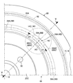
- FIG. 1 is a partial sectional view showing a first embodiment of a friction brake device according to the present invention configured as an electromagnetic vehicle brake device, cut along a cut surface passing through a rotation axis. It is the partial front view which looked at 1st embodiment from the right side of FIG.
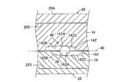
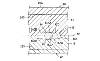
- FIG. 3 is a partial cross-sectional view taken along line III-III in FIG. It is a fragmentary sectional view showing a force transmission mechanism about the case where the 1st and 2nd press members are displaced relatively.
- FIG. 7 is a partial cross-sectional view taken along the line VII-VII in FIG. 6. It is a fragmentary sectional view which shows one modification of the cam surface of a force transmission mechanism. It is a fragmentary sectional view which shows another modification of the cam surface of a force transmission mechanism.
- FIG. 1 is a partial cross-sectional view showing a first embodiment of a friction brake device according to the present invention configured as an electromagnetic vehicle brake device, cut along a cutting plane passing through a rotation axis
- FIG. 3 is a partial sectional view taken along the line III-III in FIG. 2.
- 1 is a cross-sectional view taken along the line II of FIG.
- reference numeral 10 denotes an entire brake device, and the brake device 10 includes a brake rotor 12, a first pressing member 14, and a second pressing member 16.
- the brake rotor 12 rotates around a rotation axis 18 together with a wheel rotation shaft 17 (not shown).
- the brake rotor 12 includes a main rotor 20 that is integral with the rotary shaft 17 and a sub-rotor 22 that rotates integrally with the main rotor.
- the main rotor 20 and the first pressing member 14 are formed of a metal material having paramagnetism
- the second pressing member 16 and the sub-rotor 22 may be formed of a metal material having no paramagnetism.
- the main rotor 20 has a disk portion 20A and a cylindrical portion 20B that are spaced along the rotation axis 18.
- the disk portion 20 ⁇ / b> A is integrally connected to the rotating shaft 17 at the inner peripheral portion, and extends substantially in the shape of an annular plate around the rotating axis 18 perpendicular to the rotating axis 18.
- the cylindrical portion 20B is integrally connected to the outer peripheral portion of the disk portion 20A and extends in a cylindrical shape around the rotation axis 18.
- the sub-rotor 22 extends in the shape of an annular plate around the rotation axis 18 perpendicular to the rotation axis 18, and is connected to the end of the cylindrical portion 20B opposite to the disk portion 20A by a plurality of bolts 24 at the outer periphery. Has been.
- the disk portion 20A and the sub-rotor 22 have the same thickness, and the thickness of the cylindrical portion 20B is smaller than the thickness of the disk portion 20A and the sub-rotor 22.
- the cylindrical portion 20 ⁇ / b> B extends in a cylindrical shape around the rotation axis 18, it has higher rigidity than the disk portion 20 ⁇ / b> A and the sub-rotor 22.
- each of the disk portion 20A and the sub-rotor 22 extends in the shape of an annular plate around the rotation axis 18 perpendicular to the rotation axis 18, and is separated from each other along the rotation axis 18.
- the cylindrical portion 20 ⁇ / b> B functions as a connecting portion that cooperates with the bolt 24 to integrally connect the outer peripheral portion of the disk portion 20 ⁇ / b> A and the sub-rotor 22.
- the disk portion 20A, the cylindrical portion 20B, and the sub-rotor 22 have a U-shaped cross-sectional shape opened inward in the radial direction when viewed from a radial cut surface passing through the rotation axis 18.
- the surfaces of the disk portion 20A and the sub-rotor 22 that face each other include a first friction surface 20S and a second friction surface 22S that extend around the rotation axis 18 in parallel to each other perpendicular to the rotation axis 18, respectively. I have decided.
- the rotary shaft 17 is rotatably supported around the rotary axis 18 by a sleeve portion 28A of a wheel support member 28 as a stationary member via a pair of ball bearings 26.
- a space between the pair of ball bearings 26, the rotating shaft 17, and the sleeve portion 28A is filled with a lubricant such as grease.
- a pair of seal members 30 are arranged on both sides in the axial direction with respect to the pair of ball bearings 26, and the seal member 30 is disposed between the rotary shaft 17 and the sleeve portion 28 ⁇ / b> A so that dust and muddy water do not enter the ball bearing 26. It is sealed.
- the disk portion 20A of the main rotor 20 is a wheel rim formed by four bolts 32 and nuts screwed to the four bolts 32 while being spaced apart from each other by 90 ° around the rotation axis 18. It is designed to be integrally connected to the part. Therefore, the rotating shaft 17 and the brake rotor 12 (the main rotor 20 and the sub-rotor 22) rotate around the rotating axis 18 together with the wheels.
- the first pressing member 14 has an annular shape extending around the rotation axis 18 over the entire circumference.
- the first pressing member 14 has an annular groove 14 ⁇ / b> B that extends around the rotation axis 18 over the entire circumference and opens outward in the radial direction.
- a solenoid 34 is disposed in the annular groove 14 ⁇ / b> B, and the solenoid 34 extends annularly around the rotation axis 18.
- energization to the solenoid 34 is controlled by an electronic control unit.
- the driver's braking operation amount such as the depression force on the brake pedal may be detected, and the control current for the solenoid 34 may be controlled so that the current value increases as the braking operation amount increases.
- the second pressing member 16 has an annular plate-like portion 16X and a cylindrical portion 16Y that are integral with each other.
- the annular plate-like portion 16X extends around the rotation axis 18 over the entire circumference, and the outer peripheral portion of the annular plate-like portion 16X is separated from the first pressing member 14 in the first pressing member. 14 and the sub-rotor 22.
- the cylindrical portion 16Y is fitted to the sleeve portion 28A of the wheel support member 28 with a slight play, and is provided on the inner surface of the cylindrical portion 16Y and the outer surface of the sleeve portion 28A and extends along the rotation axis 18.
- a key 36 is fitted in the. Therefore, the second pressing member 16 is supported by the wheel support member 28 so as not to rotate around the rotation axis 18 and to be displaceable along the rotation axis 18.
- the annular plate-like portion 16X has a columnar shoulder portion 16C facing radially outward on the first pressing member 14, and the first pressing member 14 is a cylinder facing the shoulder portion 16C in the radial direction.
- the shoulder portion 14C has a shape.
- the shoulder portions 14C and 16C have regions spaced radially from each other at eight positions equally spaced around the rotation axis 18, and a ball is interposed between the shoulder portions 14C and 16C in these regions. 38 is interposed.
- the ball 38 is formed of a material such as a substantially rigid metal. Therefore, the first pressing member 14 is supported by the second pressing member 16 so as to be rotatable around the rotation axis 18 through the ball 38 and to be displaceable along the rotation axis 18.
- the first pressing member 14 and the second pressing member 16 have eight cam surfaces 14Z and 16Z that can be engaged with the corresponding balls 38 on the side surfaces facing each other in the region between the shoulder portion 14C and the shoulder portion 16C. Respectively. As shown in FIG. 2, each of the cam surfaces 14 ⁇ / b> Z and 16 ⁇ / b> Z is provided at a circumferential position where the corresponding ball 38 is disposed, and extends in an arc shape with the rotation axis 18 as the center.
- the cam surface 14 ⁇ / b> Z includes a curved portion 14 ⁇ / b> ZA that opens toward the second pressing member 16, and a planar inclined portion that extends continuously on both sides of the curved portion. 14ZB and 14ZC.
- the inclined portions 14ZB and 14ZC are inclined with respect to a virtual plane 40 perpendicular to the rotation axis 18 so as to approach the second pressing member 16 as the distance from the curved portion 14ZA increases.
- the cam surface 16Z has a curved portion 16ZA that opens toward the first pressing member 14, and planar inclined portions 16ZB and 16ZC that extend continuously on both sides of the curved portion. ing.
- the inclined portions 16ZB and 16ZC are inclined with respect to the virtual plane 40 so as to approach the first pressing member 14 as the distance from the curved portion 16ZA increases.
- the inclination angles of the inclined portion 14ZB and the like with respect to the virtual plane 40 are the same. Therefore, the inclined portions 14ZB and 16ZC and 14ZC and 16ZB facing each other in the radial direction of each ball 38 are inclined in the same direction with respect to the virtual plane 40 and extend parallel to each other.
- the inner peripheral portion of the sub-rotor 22 is fitted to the sleeve portion 28A of the wheel support member 28 as shown in FIG.
- a seal member 42 that extends over the entire circumference around the rotation axis 18 is disposed.
- the main rotor 20 and the sub-rotor 22 cooperate with the rotating shaft 17, the wheel support member 28, and the seal member 42 to form a sealed space 44, and the first pressing member 14, the second pressing member 16, The solenoid 34 and the ball 38 are accommodated in the sealed space 44.
- the sealed space 44 is filled with a lubricant. Therefore, substantially no frictional force is generated between the balls 38 and the shoulders 14C and 16C and between the balls 38 and the cam surfaces 14Z and 16Z.
- first rotational friction members 50 are arranged between the first pressing member 14 and the disk portion 20 ⁇ / b> A of the main rotor 20. It is substantially disk-shaped around an axis 52 parallel to the rotation axis 18.
- second rotational friction members 54 are disposed between the second pressing member 16 and the sub-rotor 22, and each rotational friction member 54 is centered on an axis 56 parallel to the rotational axis 18. It has a substantially disk shape.
- the axes 52 and 56 are aligned with each other, and the first rotating friction member 50 and the second rotating friction member 54 are spaced 90 ° around the rotation axis 18 with respect to each other.
- the first rotary friction member 50 has friction portions 50A and 50B on both side surfaces of the outer peripheral portion, and the friction portions 50A and 50B can be frictionally engaged with the side surfaces of the disk portion 20A and the first pressing member 14, respectively. It has become.
- the second rotational friction member 54 has friction portions 54A and 54B on both side surfaces of the outer peripheral portion so that the friction portions 54A and 54B can be frictionally engaged with the side surfaces of the sub-rotor 22 and the second pressing member 16, respectively. It has become.
- Each friction part extends in the form of an annular band around the axes 52 and 56 of the rotary friction members 50 and 54 in a state of protruding from the side surface of the disk-shaped main body.
- the friction part may be formed integrally with the disk-shaped main body by manufacturing the first rotating friction member 50 and the second rotating friction member 54 by, for example, a powder sintering method.
- the friction portion may be formed by attaching an annular belt-like friction material to the side surface of the main body by bonding or other means.
- the friction portions 50A, 50B and 54A, 54B are made of the same friction material, they may be made of different friction materials.
- the first pressing member 14 and the second pressing member 16 are positioned at the standard positions shown in FIG.
- the distance between the cam surfaces 14Z and 16Z in the direction along the rotation axis 18 is minimized, and the ball 38 separates the cam surfaces 14Z and 16Z to separate the two pressing surfaces. No force is generated to separate the members 14 and 16. Therefore, the friction portions 50A and 50B of the first rotating friction member 50 do not substantially frictionally engage with the friction surface 20S of the disk portion 20A and the outer surface of the first pressing member 14, respectively.
- the friction portions 54 ⁇ / b> A and 54 ⁇ / b> B of the second rotational friction member 54 are not substantially frictionally engaged with the friction surface 22 ⁇ / b> S of the sub-rotor 22 and the outer surface of the second pressing member 16, respectively.
- External gears 58 and 60 are provided on the outer peripheral portions of the main body of the first rotary friction member 50 and the second rotary friction member 54, respectively.
- the external gears 58 and 60 are the inner periphery of the cylindrical portion 20B of the main rotor 20.
- the inner gears 62 and 64 provided on the surface mesh with each other. Therefore, the first rotational friction member 50 and the second rotational friction member 54 are displaced relative to the cylindrical portion 20B around the rotation axis 18 so as to roll on the inner peripheral surface of the cylindrical portion 20B of the main rotor 20. Is possible.
- the first pressing member 14 and the second pressing member 16 have shelves 66 and 68 radially inward with respect to the first rotating friction member 50 and the second rotating friction member 54, respectively.
- External gears 70 and 72 that mesh with the external gears 58 and 60 of the first rotating friction member 50 and the second rotating friction member 54 are provided on the outer peripheral surfaces of the shelves 66 and 68, respectively.
- the external gears 58 and 60 of the rotational friction members 50 and 54 mesh with the internal gears 62 and 64 of the cylindrical portion 20B of the main rotor 20 on the radially outer side, and the pressing members 14 and 16 on the radially inner side. Are engaged with the external gears 70 and 72, respectively.
- the first rotational friction member 50 and the second rotational friction member 54 are planetary gear mechanisms 74 and 76 having internal gears 62 and 64 as internal gears and external gears 70 and 72 as sun gears, respectively. Function.
- the solenoid 34 when a braking operation is performed by the driver, a control current corresponding to the braking operation amount is supplied to the solenoid 34, and the first pressing member 14 and the disk are electromagnetically generated by the solenoid 34.
- An attractive force acts between the portion 20A. Therefore, since the first pressing member 14 is pressed against the disk portion 20A, the friction portions 50A and 50B of the first rotating friction member 50 are respectively in contact with the friction surface 20S of the disk portion 20A and the first pressing member 14. Frictionally engages the outer surface. Therefore, the solenoid 34 functions as a pressing force control mechanism that controls the pressing force that presses the first pressing member 14 against the disk portion 20A in cooperation with the first pressing member 14 and the disk portion 20A.
- the first rotational friction member 50 If a wheel not shown in the drawing is rotating, the first rotational friction member 50 generates a rotational torque around the rotational axis 18 due to a frictional force between the friction part 50A and the friction surface 20S of the disk part 20A. Receiving and trying to rotate around the rotation axis 18 relative to the first pressing member 14. Further, the first rotating friction member 50 tries to rotate the first pressing member 14 around the rotation axis 18 by the frictional force between the friction portion 50 ⁇ / b> B and the outer surface of the first pressing member 14.
- the first pressing member 14 is supported by the second pressing member 16 so as to be rotatable around the rotation axis 18, but the second pressing member 16 cannot rotate around the rotation axis 18. Therefore, the first pressing member 14 rotates around the rotation axis 18 relative to the second pressing member 16. As a result, the first pressing member 14 and the second pressing member 16 are displaced along the virtual plane 40 as shown in FIG. 4, so that the cam surfaces 14Z and 16Z at the position of the ball 38 try to approach each other. To do. However, since the ball 38 is not compressed and deformed, a so-called wedge effect is generated, and the first pressing member 14 and the second pressing member 16 are relatively displaced along the rotation axis 18 in a direction away from each other.
- the ball 38 and the cam surfaces 14Z and 16Z cooperate with each other to displace the first pressing member 14 and the second pressing member 16 along the rotation axis 18 in a direction away from each other. Further, the ball 38 and the cam surfaces 14Z and 16Z cooperate with each other to transmit the rotational torque around the rotation axis 18 from the first pressing member 14 to the second pressing member 16, and to apply the rotational torque to the two pressing forces. It converts into the force which separates a member. Further, the ball 38 and the cam surfaces 14Z and 16Z transmit the reaction force generated when the friction engagement member is pressed against the friction surface by the pressing member between the two pressing members.
- the ball 38 and the cam surfaces 14Z and 16Z transmit the rotational torque between the first pressing member 14 and the second pressing member 16, and generate a force that separates the two pressing members in the direction along the rotation axis 18.
- a force transmission mechanism 46 that transmits reaction force is configured.
- the force transmission mechanism 46 converts the relative rotational torque between the first pressing member 14 and the second pressing member 16 into a pressing force.
- the first pressing member 14 and the second pressing member 16 respectively press the first rotating friction member 50 and the second rotating friction member 54 with a high pressing force, and rotate with respect to the friction surfaces 20S and 22S.
- the friction members 50 and 54 are pressed with a high pressing force.
- the ball 38 and the cam surfaces 14Z and 16Z also function as a positioning mechanism that cooperates with each other to position the first pressing member 14 and the second pressing member 16 at the standard position.
- the relative rotational torque is proportional to the attractive force due to the electromagnetic force generated by the solenoid 34, and the force for separating the first pressing member 14 and the second pressing member 16 is proportional to the relative rotational torque. Therefore, the pressing force with which the first pressing member 14 and the second pressing member 16 press the rotating friction members 50 and 54 against the disk portion 20A and the sub disk 22 is proportional to the amount of braking operation by the driver.
- the second pressing member 16 is prevented from rotating around the rotation axis 18 relative to the wheel support member 28 by the key 36 and the keyway for receiving the key 36. Therefore, the wheel support member 28 functions as a rotational torque carrying member that receives the rotational torque that the second pressing member 16 receives from the first pressing member 14.
- the force transmission mechanism 46 transmits the rotational torque around the rotation axis 18 from the first pressing member 14 to the second pressing member 16 and the force transmitting mechanism 46. Due to the wedge action, the rotational torque is converted into a force separating the two pressing members. Further, the reaction force generated by the pressing of the pressing members 14 and 16 is transmitted to the other pressing member via the force transmission mechanism 46.
- the force transmission mechanism 46 functions as a force-increasing mechanism in cooperation with the wheel support member 28 as a stationary member, it is possible to generate a higher braking force than when the force transmission mechanism 46 is not provided. it can.
- the reaction force generated by pressing the friction engagement member against the friction surface by the pressing member is supported by the member different from the pressing member.
- the structure can be simplified as compared with the brake device provided. Further, a higher braking torque can be generated as compared with the brake device described in the above-mentioned publication, in which the friction engagement member is pressed against only one friction surface of the brake disk.
- the distance between the rotation axis 18 and the center of the ball 38 is 80 mm
- the distance between the rotation axis 18 and the rotation axes 52 and 56 is 120 mm
- the rotation axes 52 and 56 are in friction with each other.
- the distance from the center of the parts 50A, 50B and 54A, 54B is 25 mm.
- the distance from the rotation axis 18, the external gears 58 and 60 of the rotary friction members 50 and 54, and the internal gears 62 and 64 of the main rotor 20 to the meshing portion is 150 mm.
- the distance from the rotation axis 18, the external gears 58 and 60 of the rotational friction members 50 and 54, and the meshing portion of the pressing members 14 and 16 to the external gears 70 and 72 is 90 mm.
- the friction coefficient of each friction contact portion is ⁇
- the pressing force due to the electromagnetic force generated by the solenoid 34 is F1 (kgf)
- the pressing force due to the rotation torque being converted into the pressing force by the force transmission mechanism 46 is F2 (kgf).
- the total pressing force F of the first pressing member 14 and the second pressing member 16 that is, the pressing force F by which the pressing members 14 and 16 press the rotary friction members 50 and 54 against the disk portion 20A and the sub-rotor 22, respectively.
- F1 must be a positive value so that the force transmission mechanism 46 does not self-lock.
- F F1 + F2 (1)
- Trv Braking torque Trv generated when the rotational friction members 50 and 54 are rotated around the rotation axis 18 relative to the disk portion 20A and the sub-rotor 22 while being pressed against the disk portion 20A and the sub-rotor 22 by the pressing members 14 and 16, respectively.
- the braking torque Tc in the conventional general brake device in which the rotational friction members 50 and 54 are simply pressed against the disk portion 20A and the sub-rotor 22 by the pressing force F1 is expressed by the following equation (8).
- the braking torque Tc is generated by rotating around the rotation axis 18 in a state where the rotating friction members 50 and 54 do not rotate but are pressed against the disk portion 20A and the sub-rotor 22 by the pressing force F1.
- the disk portion 20A, the cylindrical portion 20B, and the sub-rotor 22 have a U-shaped cross-sectional shape that is opened inward in the radial direction when viewed in a radial cut surface passing through the rotation axis 18. There is no.
- the pressing members 14 and 16 are disposed between the disk portion 20A and the sub-rotor 22, and press the rotational friction members 50 and 54 in a direction away from each other.
- a caliper that extends over both sides of the brake rotor and supports the friction member and the pressing device and carries the reaction force of the pressing force of the pressing device as in the conventional disc brake device and the second embodiment described later. It is also unnecessary to increase the caliper rigidity. Further, since the disk portion 20A and the sub-rotor 22 extend around the rotation axis 18 over the entire circumference, the rigidity of the brake rotor 12 is improved as compared with a caliper that extends only in an arc around the rotation axis. Can be high.
- the first pressing member 14 can rotate about the rotation axis 18, and the second pressing member 16 cannot rotate about the rotation axis 18.
- both the first and second pressing members can rotate around the rotation axis 18, and the first and second pressing members can rotate more than a predetermined amount by the stationary member. It may be blocked.
- FIG. 5 is a cross-sectional view showing a second embodiment of a friction brake device according to the present invention configured as a vehicle brake device, cut along a cutting plane passing through a rotation axis
- FIG. 6 is a second embodiment.
- FIG. 7 is a partial cross-sectional view taken along the line VII-VII in FIG. 5 is a cross-sectional view taken along line VV in FIG. 5 to 7, the same members as those shown in FIGS. 1 to 4 are denoted by the same reference numerals as those shown in these drawings.
- the main rotor 20 does not have the cylindrical portion 20B and is a member different from the rotating shaft 17. Further, the disc-shaped disk portion 20 ⁇ / b> A of the main rotor 20 is integrally connected to the sub-rotor 22 by a connection portion 80 made of a fin for heat dissipation.
- the rotating shaft 17 has a flange portion 17A at an outer end portion, and the inner peripheral portion of a rim portion 20C integrated with the disc portion 20A is connected to the flange portion 17A by four bolts 32. Therefore, although not shown in the figure, the bolt 32 and the nut screwed to the bolt 32 integrally connect the rim portion 20C together with the flange portion 17A to the disc portion of the wheel.
- the first rotating friction member 50 and the second rotating friction member 54 are disposed on both sides of the disk portion 20A and the sub-rotor 22 so as to face the outer surfaces thereof.
- the first pressing member 14 and the second pressing member 16 are arranged on the opposite side of the disk portion 20A and the sub-rotor 22 with respect to the first rotating friction member 50 and the second rotating friction member 54, respectively.
- the first rotational friction member 50 and the second rotational friction member 54 are formed on the caliper via the balls 38A and 38B by a caliper 88 extending across the outer periphery of the brake rotor 12 and having a substantially U-shaped cross section. It is rotatably supported around the rotation axes 52 and 56.
- the caliper 88 includes halves 88A and 88B integrally connected by connecting means such as bolts or welding, and the half 88B is fixed integrally to the stationary member 90 by connecting means such as bolts.
- the balls 38A and 38B are respectively disposed between the cylindrical inner surfaces 14C and 16C of the first pressing member 14 and the second pressing member 16 and the cylindrical inner surfaces 88AC and 88BC provided on the halves 88A and 88B. It is intervened.
- cam surfaces 88AZ and 88BZ facing the cam surfaces 14Z and 16Z in the direction along the rotation axes 52 and 56 with the balls 38A and 38B interposed therebetween are respectively provided on the inner surfaces of the half bodies 88A and 88B. Is provided.
- the cam surfaces 88AZ and 88BZ have the same relationship with the cam surfaces 14Z and 16Z as the cam surfaces 16Z and 14Z of the first embodiment.
- the solenoid 34 is fixed to the outer surface of the radially inner peripheral portion of the half body 88A.
- the cam surfaces 14Z and 88AZ constitute a force transmission mechanism 46A corresponding to the force transmission mechanism 46 of the first embodiment in cooperation with the ball 38A.
- the force transmission mechanism 46 ⁇ / b> A transmits rotational torque between the first pressing member 14 and the half body 88 ⁇ / b> A, generates a force that separates the half body 88 ⁇ / b> A in the direction along the rotational axis 18, and transmits a reaction force.
- the cam surfaces 16Z and 88BZ together with the ball 38B constitute a force transmission mechanism 46B corresponding to the force transmission mechanism 46 of the first embodiment.
- the force transmission mechanism 46 ⁇ / b> B transmits rotational torque between the second pressing member 16 and the half body 88 ⁇ / b> B, generates a force that separates the half body 88 ⁇ / b> B in the direction along the rotational axis 18, and transmits a reaction force.
- These force transmission mechanisms 46A and 46B convert the relative rotational torque between the first pressing member 14 and the half body 88A and between the second pressing member 16 and the half body 88B into a pressing force, respectively. Accordingly, the first pressing member 14 and the second pressing member 16 press the first rotating friction member 50 and the second rotating friction member 54 with a high pressing force, respectively, and against the friction surfaces 20S and 22S. The rotary friction members 50 and 54 are pressed with a high pressing force.
- the ball 38A, the cam surface 14Z, and the cam surface 88AZ also function as a positioning mechanism that cooperates with each other to position the first pressing member 14 at the standard position.
- the ball 38B, the cam surface 16Z, and the cam surface 88BZ also function as a positioning mechanism that cooperates with each other to position the second pressing member 16 at the standard position.
- the relative rotational torque is proportional to the attractive force due to the electromagnetic force generated by the solenoid 34, and the force that separates the first pressing member 14 and the half body 88A and the second pressing member 16 and the half body 88B are separated.
- the force is proportional to the relative rotational torque. Therefore, the pressing force with which the first pressing member 14 and the second pressing member 16 press the rotating friction members 50 and 54 against the disk portion 20A and the sub disk 22 is proportional to the amount of braking operation by the driver.
- the half bodies 88A and 88B are prevented from rotating around the rotation axis 18 by the stationary member 90. Therefore, the half bodies 88 ⁇ / b> A and 88 ⁇ / b> B and the stationary member 90 function as a rotational torque carrying member that receives the rotational torque received from the first pressing member 14 and the second pressing member 16.
- the shelves 66 and 68 of the first pressing member 14 and the second pressing member 16 protrude in directions closer to each other than the main body portion of the pressing member, and are opposed to the first rotating friction member 50 and the second rotating friction member 54. It has a cylindrical shape extending around the entire circumference of the rotation axis 18 on the radially inner side.
- the external gears 70 and 72 provided on the shelves 66 and 68 are respectively connected to the external gears 58 and 60 of the first rotational friction member 50 and the second rotational friction member 54. Meshed.
- a ring gear member 92 having a substantially cylindrical shape is fixed to the outer periphery of the main rotor 20, that is, the cylindrical outer peripheral surfaces of the disk portion 20 ⁇ / b> A and the sub-rotor 22 by means such as welding.
- the ring gear member 92 extends around the rotation axis 18.
- Ring gears 94A and 94B are provided on the inner peripheral surfaces of both ends of the ring gear member 92, and the ring gears 94A and 94B mesh with the external gears 58 and 60 of the rotary friction members 50 and 54, respectively.
- the external gears 58 and 60 of the rotational friction members 50 and 54 mesh with the internal gears 94A and 94B of the ring gear member 92 on the radially outer side, and the external gears of the pressing members 14 and 16 on the radially inner side. Meshes with 70 and 72, respectively. Therefore, the first rotational friction member 50 and the second rotational friction member 54 are planetary gears of planetary gear mechanisms 74 and 76 in which the internal gears 94A and 94B are internal gears and the external gears 70 and 72 are sun gears, respectively. Function.
- the solenoid 34 cooperates with the first pressing member 14 and the disk portion 20A to control the pressing force that presses the first pressing member 14 against the disk portion 20A. Functions as a pressure control mechanism.
- the first rotational friction member 50 If a wheel not shown in the drawing is rotating, the first rotational friction member 50 generates a rotational torque around the rotational axis 18 due to a frictional force between the friction part 50A and the friction surface 20S of the disk part 20A. Receiving and trying to rotate around the rotation axis 18 relative to the first pressing member 14. Further, the first rotating friction member 50 tries to rotate the first pressing member 14 around the rotation axis 18 by the frictional force between the friction portion 50 ⁇ / b> B and the inner surface of the first pressing member 14.
- the first pressing member 14 is supported by the half body 88A of the caliper 88 so as to be rotatable around the rotation axis 18, but the half body 88A cannot rotate around the rotation axis 18. Therefore, the first pressing member 14 rotates around the rotation axis 18 relative to the half body 88A. As a result, since the first pressing member 14 and the half body 88A are relatively displaced, a so-called wedge effect is generated as in the case of the first embodiment, and the first pressing member 14 and the half body 88A have the rotation axis. 18 are pushed in directions away from each other.
- the half body 88 ⁇ / b> B presses the second pressing member 16 and the second rotating friction member 54 against the sub-rotor 22.
- the second rotational friction member 54 receives rotational torque around the rotational axis 18 due to the frictional force between the friction portion 54 ⁇ / b> A and the friction surface 22 ⁇ / b> S of the sub-rotor 22, and the rotational axis 18 is relative to the second pressing member 16. Try to rotate around. Further, the second rotating friction member 54 tries to rotate the second pressing member 16 around the rotation axis 18 by the frictional force between the friction portion 54 ⁇ / b> B and the inner surface of the second pressing member 16.
- the second pressing member 16 rotates around the rotation axis 18 relative to the half 88B.
- a so-called wedge effect is generated as in the case of the relative displacement of the first pressing member 14 and the half body 88A. 16 and the half 88B are pressed along the rotation axis 18 in a direction away from each other.
- the force transmission mechanism 46A transmits the rotational torque around the rotation axis 18 from the first pressing member 14 to the half body 88A, and the wedge transmission of the force transmission mechanism 46A.
- the rotational torque is converted into a force that separates the two members.
- the rotational torque around the rotational axis 18 is transmitted from the second pressing member 16 to the half body 88B by the force transmission mechanism 46B, and the rotational torque is applied to the two members by the wedge action of the force transmission mechanism 46B. It is converted into a force for separating.
- the reaction force generated by the pressing of the pressing members 14 and 16 is transmitted to the other pressing member via the force transmission mechanisms 46A and 46B and the caliper 88.
- the rotation axes 52 and 56 of the first rotational friction member 50 and the second rotational friction member 54 are not only aligned with each other, but also the force transmission mechanism 46A and It is aligned with the center of 46B balls 38A and 38B. Therefore, as compared with the case where the rotation axes 52 and 56 are not aligned with the centers of the balls 38A and 38B, the rotary friction members 50 and 54 are preferably moved by the pressing force generated by the force transmission mechanisms 46A and 46B. It is possible to press against the sub-rotor 22.
- the force transmission mechanisms 46A and 46B of the second embodiment function in the same manner as the force transmission mechanism 46 of the first embodiment. Therefore, if the dimensions such as the distance between the rotation axis 18 and the centers of the balls 38A and 38B are the same as in the first embodiment, the braking torque servo ratio Rbt1 is the same as in the first embodiment. is there.
- the friction portions 50A, 50B and 54A, 54B are integrated with the disc-shaped main bodies of the first rotational friction member 50 and the second rotational friction member 54, respectively. Is formed. Therefore, the number of parts can be reduced and the structure can be simplified as compared with the case where these friction parts are separate from the main bodies of the rotary friction members 50 and 54.
- the cam surfaces 14Z and 16Z of the force transmission mechanism 46 include the curved portions 14ZA and 16ZA and the planar inclined portions 14ZB, 16ZB and 14ZC extending on both sides of the curved portion, respectively. 16ZC.
- the cam surface of the force transmission mechanism 46 may have another shape as long as it has an inclined surface inclined in the same direction with respect to the virtual plane 40 perpendicular to the rotation axis 18.
- the cam surface 14Z may have a mountain shape, and the cam surface 16Z may have a valley shape that receives the cam surface 14Z.
- a rolling element such as a ball may be interposed between the cam surfaces of the first and second pressing members.
- the inclined portions 14ZB, 16ZB and 14ZC, 16ZC extending on both sides of the curved portion are inclined so that the inclination angle with respect to the virtual plane 40 gradually decreases as the distance from the curved portion increases. May be curved.
- the rolling element may be a cylindrical roller or a tapered roller.
- the two members having cam surfaces facing each other rotate relative to each other around the rotation axis 18, and the rotational torque increases in the direction along the rotation axis 18 as the relative displacement amount of these members increases. It is possible to gradually increase the force component decomposed into Therefore, the brake characteristic of the brake device can be changed to a progressive brake characteristic.
- the cam surfaces 14Z, 16Z, etc. have the curved portions 14ZA, 16ZA, etc., respectively, but the inclined portions such as the inclined portion 14ZB are not provided with the curved portions. It may consist only of parts.
- the friction engagement portions 14A and 16A have the same size, and the first rotation friction member 50 and the second rotation friction engagement member 54 are They have the same diameter. However, they may have different sizes and diameters.
- the friction portions on both sides of the first rotational friction member 50 and the second rotational friction engagement member 54 have the same radius around the axes 52 and 56. It is provided in the position. However, the friction portions on both sides of the rotating friction members 50 and 54 may be provided at positions having different radii.
- the cylindrical portion 20B is formed integrally with the disc portion 20A to form the main rotor 20.
- the cylindrical portion 20B may be formed integrally with the sub-rotor 22, and the disc portion 20A, the cylindrical portion 20B, and the sub-rotor 22 may be formed separately.
- the main rotor 20 and the sub-rotor 22 cooperate with the rotating shaft 17, the wheel support member 28, and the seal member 42 to form the sealed space 44. It may not be formed.
- the pressing members 14 and 16 and the rotating friction members 50 and 54 are accommodated in the sealed space 44. Therefore, compared with the case where a pressing member etc. are not accommodated in sealed space, the temperature of these members rises easily at the time of operation of brake equipment 10.
- the friction engagement member is formed of a ceramic friction material having excellent heat resistance as described above, a decrease in braking force due to a temperature rise is small.
- the main rotor 20 and the subrotor 22 may be provided with the fin for air cooling so that the temperature rise of those members may be suppressed.
- the first pressing member 14 is urged against the disk portion 20A by the electromagnetic force generated by the solenoid 34.
- the means for urging the pressing member may be modified to be hydraulic, for example.
- the brake device of each embodiment is a brake device for vehicles, the brake device of this invention may be applied to uses other than a vehicle.
Landscapes
- Engineering & Computer Science (AREA)
- General Engineering & Computer Science (AREA)
- Mechanical Engineering (AREA)
- Braking Arrangements (AREA)
- Retarders (AREA)
Abstract
摩擦面(20S、22S)を有し回転軸線(18)の周りに回転するブレーキロータ(20)と、回転軸線に平行な自転軸線(52、56)の周りに回転可能な回転摩擦部材(50、54)と、押圧部材(14、16)を回転摩擦部材に対し押圧して回転摩擦部材を摩擦面に対し押圧する押圧装置(34)とを有する摩擦ブレーキ装置(10)。ブレーキロータ、回転摩擦部材、押圧部材は、回転摩擦部材を遊星歯車とする遊星歯車機構(74、76)を構成しており、回転摩擦部材は摩擦面及び押圧部材と摩擦係合し、押圧部材と非回転部材(16)との間には、相対回転トルクを押圧力に変換する押圧力増力機構(46)が設けられている。
Description
本発明は、摩擦ブレーキ装置に係り、更に詳細にはブレーキロータに摩擦部材を押圧することにより摩擦力を発生させる摩擦ブレーキ装置に係る。
摩擦ブレーキ装置において、摩擦部材をブレーキロータに押圧すると共に、摩擦部材がブレーキロータより受ける回転トルクを利用してくさび作用を発生させ、これによりブレーキロータに対する摩擦部材の押圧力を増大させる構造が既に知られている。例えば、下記の特許文献1には、くさび作用を発生させる自己倍力機構を有する摩擦ブレーキ装置が記載されている。
この種の摩擦ブレーキ装置によれば、くさび作用による押圧力の増大が行われないブレーキ装置に比して、摩擦部材を押圧する押圧装置の押圧力を高くすることなくブレーキ装置が発生する制動力を高くすることができる。
〔発明が解決しようとする課題〕
上記特許文献1に記載されている如き従来のくさび作用を発生させる摩擦ブレーキ装置においては、摩擦部材はブレーキロータと摩擦係合し、ブレーキロータに対しその回転軸線の周りに相対回転する際の摩擦力により制動力を発生する。また、摩擦部材は摩擦力により回転軸線の周りに非回転部材に対し相対的に回転変位せしめられることによりくさび作用を発生する。
上記特許文献1に記載されている如き従来のくさび作用を発生させる摩擦ブレーキ装置においては、摩擦部材はブレーキロータと摩擦係合し、ブレーキロータに対しその回転軸線の周りに相対回転する際の摩擦力により制動力を発生する。また、摩擦部材は摩擦力により回転軸線の周りに非回転部材に対し相対的に回転変位せしめられることによりくさび作用を発生する。
しかし、摩擦部材は回転軸線の周りのブレーキロータに対する相対回転以外の運動をしないため、摩擦力により発生される制動力が制限される。よって、従来のくさび作用を発生させる摩擦ブレーキ装置には、制動力を十分に高くする上で改善の余地がある。
本発明は、くさび作用を発生させる従来の摩擦ブレーキ装置における上述の如き問題に鑑みてなされたものである。そして、本発明の主要な課題は、ブレーキロータに対する回転軸線の周りの相対回転以外の運動を摩擦部材にさせると共に、くさび作用により増大された押圧力にて摩擦部材を押圧することにより、十分に高い摩擦力を発生させることである。
〔課題を解決するための手段及び発明の効果〕
本発明によれば、回転軸線に垂直に延在する摩擦面を有し、回転軸線の周りに回転するブレーキロータと、回転軸線に平行な自転軸線の周りに回転可能な回転摩擦部材と、押圧部材を回転摩擦部材に対し押圧することにより、回転摩擦部材を摩擦面に対し押圧する押圧装置と、を有する摩擦ブレーキ装置において、ブレーキロータ、回転摩擦部材、押圧部材は、回転摩擦部材を遊星歯車とする遊星歯車機構を構成しており、回転摩擦部材は、押圧部材により摩擦面に対し押圧されると、摩擦面及び押圧部材と摩擦係合し、押圧部材と回転軸線の周りに回転不能に支持された非回転部材との間には、押圧力増力機構が設けられており、押圧力増力機構は、押圧部材と非回転部材との間の回転軸線の周りの相対回転トルクを、押圧部材を回転摩擦部材に対し押圧する押圧力に変換する、ことを特徴とする摩擦ブレーキ装置が提供される。
本発明によれば、回転軸線に垂直に延在する摩擦面を有し、回転軸線の周りに回転するブレーキロータと、回転軸線に平行な自転軸線の周りに回転可能な回転摩擦部材と、押圧部材を回転摩擦部材に対し押圧することにより、回転摩擦部材を摩擦面に対し押圧する押圧装置と、を有する摩擦ブレーキ装置において、ブレーキロータ、回転摩擦部材、押圧部材は、回転摩擦部材を遊星歯車とする遊星歯車機構を構成しており、回転摩擦部材は、押圧部材により摩擦面に対し押圧されると、摩擦面及び押圧部材と摩擦係合し、押圧部材と回転軸線の周りに回転不能に支持された非回転部材との間には、押圧力増力機構が設けられており、押圧力増力機構は、押圧部材と非回転部材との間の回転軸線の周りの相対回転トルクを、押圧部材を回転摩擦部材に対し押圧する押圧力に変換する、ことを特徴とする摩擦ブレーキ装置が提供される。
上記の構成において、押圧部材により回転摩擦部材が摩擦面に対し押圧されると、回転摩擦部材は摩擦面及び押圧部材と摩擦係合し、摩擦部材と押圧部材との間の摩擦力により押圧部材は非回転部材に対し相対的に回転軸線の周りに回転せしめられる。よって、押圧部材と非回転部材との間の相対回転トルクが、押圧力増力機構により押圧部材を回転摩擦部材に対し押圧する押圧力に変換され、これにより回転摩擦部材が摩擦面に対し押圧される押圧力が増力される。
また、ブレーキロータ、回転摩擦部材、押圧部材は、回転摩擦部材を遊星歯車とする遊星歯車機構を構成しているので、回転摩擦部材は回転軸線に平行な自転軸線の周りに自転しつつ回転軸線の周りに公転する。よって、回転摩擦部材は摩擦面及び押圧部材と摩擦係合して公転及び自転の両方による摩擦力を発生する。さらに、回転摩擦部材と摩擦面及び押圧部材との間の押圧力は押圧力増力機構により増力された押圧力である。
従って、上記構成によれば、摩擦部材がブレーキロータに対し回転軸線の周りの相対回転以外の運動をしない従来のくさび作用型摩擦ブレーキ装置に比して、制動力を十分に高くすることができる。
また、本発明によれば、上記の構成において、摩擦面は、回転軸線に沿って互いに隔置された第一及び第二の摩擦面を含み、回転摩擦部材は、それぞれ第一及び第二の摩擦面と摩擦係合可能に支持された第一及び第二の回転摩擦部材を含み、押圧部材は、それぞれ第一及び第二の摩擦面に対し第一及び第二の回転摩擦部材を押圧する第一及び第二の押圧部材であって、回転軸線に沿って変位可能に支持された第一及び第二の押圧部材を含み、押圧装置は、第一及び第二の押圧部材の一方が対応する回転摩擦部材を対応する摩擦面に対し押圧する力を制御する押圧力制御機構を含み、ブレーキロータ、第一及び第二の回転摩擦部材、第一及び第二の押圧部材は、それぞれ第一及び第二の回転摩擦部材を遊星歯車とする第一及び第二の遊星歯車機構を構成しており、第一及び第二の摩擦面は互いに対向し、第一及び第二の回転摩擦部材、第一及び第二の押圧部材、及び押圧力制御機構の少なくとも一部は、第一の摩擦面と第二の摩擦面との間に配置されているよう構成されてよい。
上記の構成によれば、第一及び第二の回転摩擦部材は、第一の摩擦面と第二の摩擦面との間において第一及び第二の押圧部材により互いに逆方向へ押圧されることによりそれぞれ第一及び第二の摩擦面に対し押圧される。回転摩擦部材として第一及び第二の2種類の回転摩擦部材があるので、例えば上記特許文献1に記載された摩擦ブレーキ装置の如く1種類の回転摩擦部材しか存在しない場合に比して、制動力を高くすることができる。
また、第一及び第二の押圧部材による押圧の反力を他方の押圧部材に伝達させることができるので、押圧の反力を受ける別の部材を設ける必要がない。よって、例えば上記特許文献1に記載された摩擦ブレーキ装置の如く押圧の反力を受ける別の部材が必要である場合に比して、摩擦ブレーキ装置の構造を単純化することができる。
また、本発明によれば、上記の構成において、第一の押圧部材は静止部材により回転軸線の周りに回転可能に、かつ、回転軸線に沿って変位可能に支持され、第二の押圧部材は静止部材により回転軸線の周りに回転不能に、かつ、回転軸線に沿って変位可能に支持され、第二の押圧部材及び静止部材は非回転部材を構成し、押圧力制御機構は少なくとも第一の押圧部材が第一の摩擦面に対し第一の回転摩擦部材を押圧する力を制御するよう構成されてよい。
上記の構成によれば、第一の回転摩擦部材が第一の押圧部材により第一の摩擦面に対し押圧されると、第一の回転摩擦部材は第一の摩擦面と摩擦係合すると共に、第一の押圧部材にも摩擦係合する。よって、第一の押圧部材は第一の回転摩擦部材との間の摩擦力による引きずりにより回転軸線の周りに回転せしめられ、これにより第一の押圧部材は第二の押圧部材に対し相対的に回転軸線の周りに回転せしめられる。従って、第一の押圧部材と非回転部材の一部である第二の押圧部材との間の相対回転トルクが、押圧力増力機構により押圧力に変換され、これにより第一及び第二の回転摩擦部材がそれぞれ第一及び第二の摩擦面に対し押圧される押圧力が増力される。
また、本発明によれば、上記の構成において、押圧力増力機構は、第一及び第二の押圧部材の間に回転軸線の周りの回転トルクを伝達し、第一及び第二の押圧部材が回転軸線の周りに相対回転変位せしめられることにより発生するくさび作用を利用して回転トルクを回転軸線に沿って第一及び第二の押圧部材を離間させる方向の力に変換すると共に、第一及び第二の回転摩擦部材がそれぞれ第一及び第二の摩擦面を押圧する反力を第一及び第二の押圧部材の間に相互に伝達する力伝達機構と、回転軸線の周りに回転不能に支持された回転トルク担持部材であって、第一及び第二の押圧部材の一方より第一及び第二の押圧部材の他方へ伝達される回転トルクを他方の押圧部材を介して受け止める回転トルク担持部材と、を有するよう構成されてよい。
上記の構成によれば、力伝達機構及び回転トルク担持部材の共働により、回転トルクを回転軸線に沿って第一及び第二の押圧部材を離間させる方向の力に変換し、その変換された力によって押圧力を増力することができる。
また、本発明によれば、上記の構成において、力伝達機構は、それぞれ第一及び第二の押圧部材に設けられ回転軸線に沿う方向に互いに対向する第一及び第二の対向面を有し、第一及び第二の対向面は回転軸線に垂直な仮想平面に対し同一の方向に傾斜する傾斜領域を有し、第一及び第二の対向面の傾斜領域の共働により、回転トルクを回転軸線の周りの周方向に伝達すると共に、回転トルクを回転軸線に平行で第一及び第二の押圧部材を離間させる方向の力に変換するよう構成されてよい。
上記の構成によれば、第一及び第二の対向面の傾斜領域の共働により、回転トルクを回転軸線の周りの周方向に確実に伝達することができると共に、回転トルクを回転軸線に平行で第一及び第二の押圧部材を離間させる方向の力に確実に変換することができる。そして、第一及び第二の押圧部材は、その変換により増力された押圧力にて第一及び第二の回転摩擦部材をそれぞれ第一及び第二の摩擦面に対し押圧することができる。
また、本発明によれば、上記の構成において、摩擦面は、回転軸線に沿って互いに隔置された第一及び第二の摩擦面を含み、回転摩擦部材は、それぞれ第一及び第二の摩擦面と摩擦係合可能に支持された第一及び第二の回転摩擦部材を含み、押圧部材は、それぞれ第一及び第二の摩擦面に対し第一及び第二の回転摩擦部材を押圧する第一及び第二の押圧部材であって、回転軸線に沿って変位可能に支持された第一及び第二の押圧部材を含み、押圧装置は、第一及び第二の押圧部材の一方が対応する回転摩擦部材を対応する摩擦面に対し押圧する力を制御する押圧力制御機構を含み、ブレーキロータ、第一及び第二の回転摩擦部材、第一及び第二の押圧部材は、それぞれ第一及び第二の回転摩擦部材を遊星歯車とする第一及び第二の遊星歯車機構を構成しており、第一及び第二の摩擦面は互いに対向する方向とは逆の方向へ面し、第一及び第二の回転摩擦部材、及び第一及び第二の押圧部材、第一及び第二の摩擦面に対し互いに反対の側に配置されているよう構成されてよい。
上記の構成によれば、第一及び第二の回転摩擦部材は、第一及び第二の摩擦面の両側において第一及び第二の押圧部材により互いに近づく方向へ押圧されることによりそれぞれ第一及び第二の摩擦面に対し押圧される。回転摩擦部材として第一及び第二の2種類の回転摩擦部材があるので、例えば上記特許文献1に記載された摩擦ブレーキ装置の如く1種類の回転摩擦部材しか存在しない場合に比して、制動力を高くすることができる。
なお、第一及び第二の押圧部材による押圧の反力を例えばキャリパの如き部材によって他方の押圧部材へ伝達させることにより、押圧の反力を有効に利用して押圧力を高くすることができる。
また、本発明によれば、上記の構成において、第一及び第二の押圧部材はキャリパにより回転軸線の周りに回転可能に、かつ、回転軸線に沿って変位可能に支持され、キャリパは非回転部材を構成し、押圧力制御機構は少なくとも第一の押圧部材が第一の摩擦面に対し第一の回転摩擦部材を押圧する力を制御するよう構成されてよい。
上記の構成によれば、第一の回転摩擦部材が第一の押圧部材により第一の摩擦面に対し押圧されると、第一の回転摩擦部材は第一の摩擦面と摩擦係合すると共に、第一の押圧部材とも摩擦係合する。よって、第一の押圧部材は第一の回転摩擦部材との間の摩擦力による引きずりにより回転軸線の周りに回転せしめられ、これにより第一の押圧部材はキャリパに対し相対的に回転軸線の周りに回転せしめられる。従って、第一の押圧部材と非回転部材であるキャリパとの間の相対回転トルクが、押圧力増力機構により押圧力に変換され、これにより第一の回転摩擦部材が第一の摩擦面に対し押圧される押圧力が増力される。
また、第一の回転摩擦部材と第一の摩擦面及び第一の押圧部材との間の増大された押圧力の反力がキャリパによって第二の押圧部材へ伝達され、第二の押圧部材は高い押圧力にて第二の回転摩擦部材を第二の摩擦面に対し押圧する。その結果、第二の回転摩擦部材は第二の摩擦面と摩擦係合すると共に、第二の押圧部材にも摩擦係合する。よって、第二の押圧部材は第二の回転摩擦部材との間の摩擦力による引きずりにより回転軸線の周りに回転せしめられ、これにより第二の押圧部材はキャリパに対し相対的に回転軸線の周りに回転せしめられる。従って、第二の押圧部材と非回転部材であるキャリパとの間の相対回転トルクが、押圧力増力機構により押圧力に変換され、これにより第二の回転摩擦部材が第二の摩擦面に対し押圧される押圧力が増力される。
また、本発明によれば、上記の構成において、押圧力増力機構は、第一の押圧部材とキャリパとの間に回転軸線の周りの回転トルクを伝達し、第一の押圧部材が回転軸線の周りに相対回転変位せしめられることにより発生するくさび作用を利用して回転トルクを回転軸線に沿って第一の押圧部材とキャリパとを離間させる方向の力に変換すると共に、第一の回転摩擦部材が第一の摩擦面を押圧する反力を第一の押圧部材よりキャリパへ伝達する第一の力伝達機構と、第二の押圧部材とキャリパとの間に回転軸線の周りの回転トルクを伝達し、第二の押圧部材が回転軸線の周りに相対回転変位せしめられることにより発生するくさび作用を利用して回転トルクを回転軸線に沿って第二の押圧部材とキャリパとを離間させる方向の力に変換すると共に、第二の回転摩擦部材が第二の摩擦面を押圧する反力を第二の押圧部材よりキャリパへ伝達する第二の力伝達機構と、回転軸線の周りに回転不能に支持された回転トルク担持部材であって、第一の押圧部材よりキャリパへ伝達される回転トルク及び第二の押圧部材よりキャリパへ伝達される回転トルクを受け止める回転トルク担持部材と、を有するよう構成されてよい。
上記の構成によれば、力伝達機構及び回転トルク担持部材の共働により、回転トルクを回転軸線に沿って第一及び第二の押圧部材が互いに近づく方向の力に変換し、その変換された力によって押圧力を増力することができる。
また、本発明によれば、上記の構成において、第一の力伝達機構は、それぞれ第一の押圧部材及びキャリパに設けられ回転軸線に沿う方向に互いに対向する第三及び第四の対向面を有し、第三及び第四の対向面は回転軸線に垂直な仮想平面に対し同一の方向に傾斜する傾斜領域を有し、第三及び第四の対向面の傾斜領域の共働により、回転トルクを回転軸線の周りの周方向に伝達すると共に、回転トルクを回転軸線に平行で第一の押圧部材及びキャリパを離間させる方向の力に変換するよう構成されてよい。
上記の構成によれば、第三及び第四の対向面の傾斜領域の共働により、回転トルクを回転軸線の周りの周方向に確実に伝達することができると共に、回転トルクを回転軸線に平行で第一の押圧部材及びキャリパを離間させる方向の力に確実に変換することができる。そして、第一の押圧部材は、その変換により増力された押圧力にて第一の回転摩擦部材を第一の摩擦面に対し押圧することができる。
また、本発明によれば、上記の構成において、第二の力伝達機構は、それぞれ第二の押圧部材及びキャリパに設けられ回転軸線に沿う方向に互いに対向する第五及び第六の対向面を有し、第五及び第六の対向面は回転軸線に垂直な仮想平面に対し同一の方向に傾斜する傾斜領域を有し、第五及び第六の対向面の傾斜領域の共働により、回転トルクを回転軸線の周りの周方向に伝達すると共に、回転トルクを回転軸線に平行で第二の押圧部材及びキャリパを離間させる方向の力に変換するよう構成されてよい。
上記の構成によれば、第五及び第六の対向面の傾斜領域の共働により、回転トルクを回転軸線の周りの周方向に確実に伝達することができると共に、回転トルクを回転軸線に平行で第二の押圧部材及びキャリパを離間させる方向の力に確実に変換することができる。そして、第二の押圧部材は、その変換により増力された押圧力にて第二の回転摩擦部材を第二の摩擦面に対し押圧することができる。
以下に添付の図を参照しつつ、本発明を幾つかの好ましい実施形態について詳細に説明する。
[第一の実施形態]
図1は、電磁式の車両用ブレーキ装置として構成された本発明による摩擦ブレーキ装置の第一の実施形態を、回転軸線を通る切断面にて切断して示す部分断面図、図2は、第一の実施形態を図1の右方より見た部分正面図、図3は、図2のIII-IIIに沿う部分断面図である。なお、図1は図2のI-Iに沿う断面図である。
図1は、電磁式の車両用ブレーキ装置として構成された本発明による摩擦ブレーキ装置の第一の実施形態を、回転軸線を通る切断面にて切断して示す部分断面図、図2は、第一の実施形態を図1の右方より見た部分正面図、図3は、図2のIII-IIIに沿う部分断面図である。なお、図1は図2のI-Iに沿う断面図である。
図1において、10はブレーキ装置を全体的に示しており、ブレーキ装置10は、ブレーキロータ12と、第一の押圧部材14及び第二の押圧部材16とを有している。ブレーキロータ12は、図には示されていない車輪の回転軸17と共に一体的に回転軸線18の周りに回転する。特に、図示の実施形態においては、ブレーキロータ12は、回転軸17と一体をなすメインロータ20と、該メインロータと共に一体的に回転するサブロータ22とを有している。メインロータ20及び第一の押圧部材14は常磁性を有する金属材料にて形成されているが、第二の押圧部材16及びサブロータ22は常磁性を有しない金属材料にて形成されていてよい。
メインロータ20は、回転軸線18に沿って隔置されたディスク部20Aと円筒部20Bとを有している。ディスク部20Aは、内周部にて回転軸17と一体に連結され、回転軸線18に垂直に回転軸線18の周りに実質的に円環板状に延在している。円筒部20Bは、ディスク部20Aの外周部と一体に接続され、回転軸線18の周りに円筒状に延在している。サブロータ22は、回転軸線18に垂直に回転軸線18の周りに円環板状に延在し、外周部にて円筒部20Bのディスク部20Aとは反対側の端部に複数のボルト24によって連結されている。
なお、ディスク部20A及びサブロータ22は、互いに同一の厚さを有し、円筒部20Bの厚さはディスク部20A及びサブロータ22の厚さよりも小さい。しかし、円筒部20Bは、回転軸線18の周りに円筒状に延在しているので、ディスク部20A及びサブロータ22よりも高い剛性を有している。
かくして、ディスク部20A及びサブロータ22は、それぞれ回転軸線18に垂直に回転軸線18の周りに円環板状に延在し回転軸線18に沿って互いに隔置された第一及び第二のディスク部として機能する。円筒部20Bは、ボルト24と共働してディスク部20A及びサブロータ22の外周部を一体的に接続する接続部として機能する。ディスク部20A、円筒部20B及びサブロータ22は、回転軸線18を通る径方向の切断面で見て径方向内方へ開いたコの字形の断面形状をなしている。ディスク部20A及びサブロータ22の互いに対向する面は、回転軸線18に垂直に互いに平行に回転軸線18の周りに全周に亘り延在する第一の摩擦面20S及び第二の摩擦面22Sをそれぞれ郭定している。
回転軸17は、一対のボールベアリング26を介して静止部材としての車輪支持部材28のスリーブ部28Aにより回転軸線18の周りに回転可能に支持されている。一対のボールベアリング26と回転軸17とスリーブ部28Aとの間の空間は、グリースの如き潤滑剤にて充填されている。一対のボールベアリング26に対し軸線方向両側には一対のシール部材30が配置されており、シール部材30は、ボールベアリング26に粉塵や泥水が侵入しないよう回転軸17とスリーブ部28Aとの間をシールしている。
図には示されていないが、メインロータ20のディスク部20Aは、回転軸線18の周りに互いに90°隔置された状態にて4本のボルト32及びこれに螺合するナットにより車輪のリム部に一体的に連結されるようになっている。従って、回転軸17及びブレーキロータ12(メインロータ20及びサブロータ22)は、車輪と共に回転軸線18の周りに回転する。
第一の押圧部材14は回転軸線18の周りに全周に亘り延在する環状をなしている。また、第一の押圧部材14は回転軸線18の周りに全周に亘り延在し径方向外方へ開いた環状溝14Bを有している。環状溝14Bにはソレノイド34が配置されており、ソレノイド34は回転軸線18の周りに環状に延在している。
図には示されていないが、ソレノイド34に対する通電は電子制御装置によって制御される。この場合、ブレーキペダルに対する踏力の如き運転者の制動操作量が検出され、制動操作量が高いほど電流値が高くなるようソレノイド34に対する制御電流が制御されてよい。
第二の押圧部材16は互いに一体をなす円環板状部16X及び円筒部16Yを有している。円環板状部16Xは回転軸線18の周りに全周に亘り延在し、円環板状部16Xの外周部は第一の押圧部材14より隔置された状態にて第一の押圧部材14とサブロータ22との間に配置されている。
円筒部16Yは車輪支持部材28のスリーブ部28Aに僅かな遊びを持って嵌合しており、円筒部16Yの内面及びスリーブ部28Aの外面に設けられ回転軸線18に沿って延在するキー溝にはキー36が嵌め込まれている。よって、第二の押圧部材16は車輪支持部材28により回転軸線18の周りに回転不能に、かつ、回転軸線18に沿って変位可能に支持されている。
円環板状部16Xは第一の押圧部材14の側において径方向外方へ面する円柱状の肩部16Cを有し、第一の押圧部材14は肩部16Cと径方向に対向する円筒状の肩部14Cを有している。肩部14C及び16Cは回転軸線18の周りに均等に隔置された8箇所において径方向に互いに隔置された領域を有しており、それらの領域における肩部14C及び16Cの間にはボール38が介装されている。ボール38は実質的に剛固な金属の如き材料にて形成されている。よって、第一の押圧部材14は第二の押圧部材16によりボール38を介して回転軸線18の周りに回転可能に、かつ、回転軸線18に沿って変位可能に支持されている。
第一の押圧部材14及び第二の押圧部材16は、肩部14Cと肩部16Cとの間の領域において互いに対向する側面に、対応するボール38に係合可能な八つのカム面14Z及び16Zをそれぞれ有している。図2に示されている如く、各カム面14Z及び16Zは、対応するボール38が配置された周方向位置に設けられており、回転軸線18を中心とする円弧状に延在している。
図3に示されている如く、カム面14Zは、第二の押圧部材16へ向けて開いた湾曲部14ZAと、該湾曲部に連続して湾曲部の両側に延在する平面状の傾斜部14ZB及び14ZCとを有している。傾斜部14ZB及び14ZCは、湾曲部14ZAより離れるにつれて第二の押圧部材16に近づくよう、回転軸線18に垂直な仮想平面40に対し傾斜している。同様に、カム面16Zは第一の押圧部材14へ向けて開いた湾曲部16ZAと、該湾曲部に連続して湾曲部の両側に延在する平面状の傾斜部16ZB及び16ZCとを有している。傾斜部16ZB及び16ZCは、湾曲部16ZAより離れるにつれて第一の押圧部材14に近づくよう、仮想平面40に対し傾斜している。
図示の実施形態においては、図3に示されている如く、仮想平面40に対する傾斜部14ZB等の傾斜角の大きさは同一である。よって、各ボール38の径方向に互いに対向する傾斜部14ZBと16ZC及び14ZCと16ZBは、仮想平面40に対し互いに同一の方向へ傾斜し、互いに平行に延在している。
特に、図示の実施形態においては、図1に示されている如く、サブロータ22の内周部は車輪支持部材28のスリーブ部28Aに嵌合している。サブロータ22の内周部とスリーブ部28Aとの間には、回転軸線18の周りに全周に亘り延在するシール部材42が配置されている。
従って、メインロータ20及びサブロータ22は、回転軸17、車輪支持部材28、シール部材42と共働して密閉空間44を形成しており、第一の押圧部材14、第二の押圧部材16、ソレノイド34及びボール38は、密閉空間44に収容されている。そして、密閉空間44には潤滑剤が充填されている。従って、各ボール38と肩部14C及び16Cとの間及び各ボール38とカム面14Z及び16Zとの間には実質的に摩擦力が発生しないようになっている。
図1に示されている如く、第一の押圧部材14とメインロータ20のディスク部20Aとの間には、四つの第一の回転摩擦部材50が配置されており、各回転摩擦部材50は回転軸線18に平行な軸線52を中心とする実質的に円板状をなしている。同様に、第二の押圧部材16とサブロータ22との間には、四つの第二の回転摩擦部材54が配置されており、各回転摩擦部材54は回転軸線18に平行な軸線56を中心とする実質的に円板状をなしている。軸線52及び56は互いに整合しており、第一の回転摩擦部材50及び第二の回転摩擦部材54は、それぞれ互いに他に対し回転軸線18の周りに90°隔置されている。
第一の回転摩擦部材50は外周部の両側面に摩擦部50A及び50Bを有し、摩擦部50A及び50Bはそれぞれディスク部20A及び第一の押圧部材14の側面に摩擦係合し得るようになっている。同様に、第二の回転摩擦部材54は外周部の両側面に摩擦部54A及び54Bを有し、摩擦部54A及び54Bそれぞれサブロータ22及び第二の押圧部材16の側面に摩擦係合し得るようになっている。各摩擦部は円板状の本体の側面より隆起した状態で回転摩擦部材50、54の軸線52、56の周りに環帯状に延在している。
なお、第一の回転摩擦部材50及び第二の回転摩擦部材54が例えば粉末焼結法によって製造されることにより、摩擦部は円板状の本体と一体に形成されてよい。また、摩擦部は、環帯状の摩擦材が本体の側面に接着又は他の手段により固定されることにより形成されてもよい。更に、摩擦部50A、50B及び54A、54Bは互いに同一の摩擦材料にて構成されているが、互いに異なる摩擦材料にて構成されていてもよい。
図1に示されている如く、ソレノイド34に制御電流が通電されていないときには、第一の押圧部材14及び第二の押圧部材16は図3に示された標準位置に位置決めされる。そして、二つの押圧部材が標準位置にあるときには、回転軸線18に沿う方向のカム面14Z及び16Zの間の距離が最小になり、ボール38がカム面14Z及び16Zを離間させることによって二つの押圧部材14及び16を離間させる力は発生しない。よって、第一の回転摩擦部材50の摩擦部50A、50Bは、それぞれディスク部20Aの摩擦面20S及び第一の押圧部材14の外面と実質的に摩擦係合しない。同様に、第二の回転摩擦部材54の摩擦部54A、54Bは、それぞれサブロータ22の摩擦面22S及び第二の押圧部材16の外面と実質的に摩擦係合しない。
第一の回転摩擦部材50及び第二の回転摩擦部材54の本体の外周部にはそれぞれ外歯車58及び60が設けられており、外歯車58及び60はメインロータ20の円筒部20Bの内周面に設けられた内歯車62及び64にそれぞれ噛合している。よって、第一の回転摩擦部材50及び第二の回転摩擦部材54は、メインロータ20の円筒部20Bの内周面上を転動するよう、回転軸線18の周りに円筒部20Bに対し相対変位可能である。
第一の押圧部材14及び第二の押圧部材16は、それぞれ第一の回転摩擦部材50及び第二の回転摩擦部材54に対し径方向内方に棚部66及び68を有している。棚部66及び68の外周面には第一の回転摩擦部材50及び第二の回転摩擦部材54の外歯車58及び60にそれぞれ噛合する外歯車70及び72が設けられている。
かくして、回転摩擦部材50及び54の外歯車58及び60は、径方向外側にてメインロータ20の円筒部20Bの内歯車62及び64にそれぞれ噛合すると共に、径方向内側にて押圧部材14及び16の外歯車70及び72にそれぞれ噛合している。よって、第一の回転摩擦部材50及び第二の回転摩擦部材54は、それぞれ内歯車62及び64を内歯車とし、外歯車70及び72を太陽歯車とする遊星歯車機構74及び76の遊星歯車として機能する。
ブレーキロータ12が回転軸線18の周りに回転すると、メインロータ20の円筒部20Bの回転がそれぞれ外歯車58及び60と内歯車62及び64との噛合部を介して第一の回転摩擦部材50及び第二の回転摩擦部材54へ伝達される。従って、第一の回転摩擦部材50及び第二の回転摩擦部材54は、それぞれディスク部20A及びサブロータ22に対し相対的に回転軸線18の周りに公転すると共に、第一の押圧部材14及び第二の押圧部材16に対し相対的に回転軸線18の周りに公転する。この場合、第一の押圧部材14及び第二の押圧部材16に対する公転速度はディスク部20A及びサブロータ22に対する公転速度よりも高い。また、軸線52及び56も回転軸線18の周りに公転し、第一の回転摩擦部材50及び第二の回転摩擦部材54はそれぞれ公転する軸線52及び56を自転軸線としてそれらの軸線の周りに自転する。
この第一の実施形態において、運転者により制動操作が行われると、制動操作量に対応する制御電流がソレノイド34に通電され、ソレノイド34により発生される電磁力によって第一の押圧部材14とディスク部20Aとの間に引力が作用する。そのため、第一の押圧部材14がディスク部20Aに対し押圧されるので、第一の回転摩擦部材50の摩擦部50A、50Bは、それぞれディスク部20Aの摩擦面20S及び第一の押圧部材14の外面と摩擦係合する。よって、ソレノイド34は、第一の押圧部材14及びディスク部20Aと共働して、第一の押圧部材14をディスク部20Aに対し押圧する押圧力を制御する押圧力制御機構として機能する。
図には示されていない車輪が回転していれば、第一の回転摩擦部材50は摩擦部50Aとディスク部20Aの摩擦面20Sとの間の摩擦力による回転軸線18の周りの回転トルクを受け、第一の押圧部材14に対し相対的に回転軸線18の周りに回転しようとする。また、第一の回転摩擦部材50は摩擦部50Bと第一の押圧部材14の外面との間の摩擦力により、第一の押圧部材14を回転軸線18の周りに回転させようとする。
第一の押圧部材14は第二の押圧部材16により回転軸線18の周りに回転可能に支持されているが、第二の押圧部材16は回転軸線18の周りに回転することができない。そのため、第一の押圧部材14は第二の押圧部材16に対し相対的に回転軸線18の周りに回転する。その結果、第一の押圧部材14及び第二の押圧部材16は図4に示されている如く仮想平面40に沿って変位するので、ボール38の位置におけるカム面14Z及び16Zは互いに接近しようとする。しかし、ボール38は圧縮変形しないので、所謂くさび効果が発生し、第一の押圧部材14及び第二の押圧部材16は回転軸線18に沿って互いに離れる方向へ相対変位する。
すなわち、ボール38及びカム面14Z、16Zは、互いに共働して第一の押圧部材14及び第二の押圧部材16を回転軸線18に沿って互いに離間する方向へ変位させる。また、ボール38及びカム面14Z、16Zは、互いに共働して第一の押圧部材14より第二の押圧部材16へ回転軸線18の周りの回転トルクを伝達すると共に、回転トルクを二つの押圧部材を離間させる力に変換する。さらに、ボール38及びカム面14Z、16Zは、摩擦係合部材が押圧部材によって摩擦面に対し押圧されることにより発生する反力を二つの押圧部材の間にて相互に伝達する。
よって、ボール38及びカム面14Z、16Zは、第一の押圧部材14及び第二の押圧部材16の間における回転トルクの伝達、回転軸線18に沿う方向に二つの押圧部材を離間させる力の発生、反力の伝達を行う力伝達機構46を構成している。この力伝達機構46は第一の押圧部材14及び第二の押圧部材16の間の相対回転トルクを押圧力に変換する。従って、第一の押圧部材14及び第二の押圧部材16はそれぞれ第一の回転摩擦部材50及び第二の回転摩擦部材54を高い押圧力にて押圧すると共に、摩擦面20S及び22Sに対し回転摩擦部材50及び54を高い押圧力にて押圧する。また、ボール38及びカム面14Z、16Zは、互いに共働して第一の押圧部材14及び第二の押圧部材16を標準位置に位置決めする位置決め機構としての機能も果たす。
なお、相対回転トルクはソレノイド34により発生される電磁力による引力に比例し、第一の押圧部材14及び第二の押圧部材16を離間させる力は相対回転トルクに比例する。よって、第一の押圧部材14及び第二の押圧部材16がそれぞれ回転摩擦部材50及び54をディスク部20A及びサブディスク22に対し押圧する押圧力は、運転者の制動操作量に比例する。
また、第二の押圧部材16はキー36及びこれを受けるキー溝により車輪支持部材28に対し相対的に回転軸線18の周りに回転することが阻止される。よって、車輪支持部材28は、第二の押圧部材16が第一の押圧部材14より受ける回転トルクを受け止める回転トルク担持部材として機能する。
かくして、第一の実施形態によれば、力伝達機構46により、回転軸線18の周りの回転トルクが第一の押圧部材14より第二の押圧部材16へ伝達されると共に、力伝達機構46のくさび作用により、回転トルクが二つの押圧部材を離間させる力に変換される。また、押圧部材14及び16の押圧により発生される反力が、力伝達機構46を介して他方の押圧部材へ伝達される。
よって、力伝達機構46のくさび作用によりブレーキロータ12の回転トルクを有効に利用して押圧力を増力することができると共に、力伝達機構46を介して行われる反力の伝達により押圧力を増力することができる。従って、力伝達機構46は静止部材としての車輪支持部材28と共働して増力機構として機能するので、力伝達機構46が設けられていない場合に比して、高い制動力を発生させることができる。
また、第一の実施形態によれば、押圧部材によって摩擦係合部材を摩擦面に対し押圧することにより発生される反力が押圧部材とは別の部材によって支持される前述の公開公報に記載されたブレーキ装置に比して、構造を簡単なものにすることができる。また、摩擦係合部材がブレーキディスクの一方の摩擦面に対してしか押圧されない前述の公開公報に記載されたブレーキ装置に比して、高い制動トルクを発生させることができる。
例えば、図1には示されていないが、回転軸線18とボール38の中心との距離を80mmとし、回転軸線18と自転軸線52、56との距離を120mmとし、自転軸線52、56と摩擦部50A、50B及び54A、54Bの中央との距離を25mmとする。また、回転軸線18と回転摩擦部材50及び54の外歯車58及び60とメインロータ20の内歯車62及び64との噛合部までの距離を150mmとする。また、回転軸線18と回転摩擦部材50及び54の外歯車58及び60と押圧部材14及び16の外歯車70及び72との噛合部までの距離を90mmとする。
また、各摩擦接触部の摩擦係数をμとし、ソレノイド34により発生される電磁力による押圧力をF1(kgf)とし、力伝達機構46により回転トルクが押圧力に変換されることによる押圧力をF2(kgf)とする。第一の押圧部材14及び第二の押圧部材16のトータルの押圧力F、すなわち、押圧部材14及び16がそれぞれ回転摩擦部材50及び54をディスク部20A及びサブロータ22に対し押圧する押圧力Fは、下記の式(1)により表される。なお、力伝達機構46においてセルフロックが生じないためには、F1が正の値でなければならない。
F=F1+F2 ……(1)
F=F1+F2 ……(1)
仮想平面40に対する力伝達機構46のカム面14Z及び16Zの傾斜角をα(rad)とし、第一の押圧部材14及び第二の押圧部材16の相対回転トルクTre(kgfm)とすると、押圧力F2は、下記の式(2)により表される。
F2=Tre/80/tanα ……(2)
F2=Tre/80/tanα ……(2)
相対回転トルクTbは押圧力をF1に比例するので、力伝達機構46の増力比をN(1よりも大きい正の値)として、押圧力F2は、下記の式(3)により表される。
F2=NF1 ……(3)
F2=NF1 ……(3)
回転摩擦部材50及び54がそれぞれ押圧部材14及び16によってディスク部20A及びサブロータ22に対し押圧された状態にてこれらに対し相対的に回転軸線18の周りに回転することにより発生される制動トルクTrvは、下記の式(4)により表される。
Trv=μF×120×2
=240μF……(4)
Trv=μF×120×2
=240μF……(4)
回転摩擦部材50及び54が摩擦部50A、50B及び54A、54Bにて摩擦接触しつつそれぞれ自転軸線52及び56の周りに自転することにより発生する抗力トルクがメインロータ20に与える抗力Frtは、下記の式(5)により表される。よって、抗力Frtによる制動トルクTrtは、下記の式(6)により表される。
Frv=μF×25/30×4
=3.33μF……(5)
Trt=Frv×150
=500μF……(6)
Frv=μF×25/30×4
=3.33μF……(5)
Trt=Frv×150
=500μF……(6)
従って、トータルの制動トルクは制動トルクTrvと自転による制動トルクTrtと和であるトータルの制動トルクTbは、下記の式7により表される。
Tb=240μF+500μF
=740μF
=740(1+N)μF1 ……(7)
Tb=240μF+500μF
=740μF
=740(1+N)μF1 ……(7)
回転摩擦部材50及び54がただ単にディスク部20A及びサブロータ22に対し押圧力F1にて押圧される従来の一般的なブレーキ装置における制動トルクTcは、下記の式(8)により表される。なお、制動トルクTcは、回転摩擦部材50及び54が自転せずにディスク部20A及びサブロータ22に対し押圧力F1にて押圧された状態で回転軸線18の周りに回転することにより発生される制動トルクである。
Tc=μF2×120×2
=240μF1……(8)
Tc=μF2×120×2
=240μF1……(8)
従って、従来の一般的なブレーキ装置との対比における第一の実施形態の制動トルクのサーボ比Rbt(=Tb/Tc)は、下記の式9により表される。よって、力伝達機構46の増力比Nが例えば3であれば、サーボ比Rbtは約12になり、増力比Nが4であれば、サーボ比Rbtは約15になる。
Rbt=740(1+N)μF1/240μF1
=3.08(1+N) ……(9)
Rbt=740(1+N)μF1/240μF1
=3.08(1+N) ……(9)
また、前述の特許文献1に記載されたブレーキ装置との対比における第一の実施形態の制動トルクのサーボ比Rbt(=Tb/Trv)は、下記の式10により表される。
Rbt=740F/240F
=3.08 ……(10)
Rbt=740F/240F
=3.08 ……(10)
特に、第一の実施形態によれば、ディスク部20A、円筒部20B及びサブロータ22は、回転軸線18を通る径方向の切断面で見て径方向内方へ開いたコの字形の断面形状をなしている。そして、押圧部材14及び16等は、ディスク部20Aとサブロータ22との間に配設され、それらに対し回転摩擦部材50及び54を互いに離れる方向へ押圧するようになっている。
よって、従来のディスクブレーキ装置や後述の第二の実施形態の如くブレーキロータの両側に跨るよう延在し摩擦部材や押圧装置を支持すると共に押圧装置の押圧力の反力を担持するキャリパは不要であり、またキャリパの剛性を高くすることも不要である。また、ディスク部20A及びサブロータ22は、回転軸線18の周りに全周に亘り延在しているので、回転軸線の周りに円弧状にしか延在しないキャリパに比してブレーキロータ12の剛性を高くすることができる。
なお、上述の第一の実施形態においては、第一の押圧部材14は回転軸線18の周りに回転可能であり、第二の押圧部材16は回転軸線18の周りに回転不能である。しかし、本発明の摩擦ブレーキ装置は、第一及び第二の押圧部材の両者が回転軸線18の周りに回転可能であり、第一及び第二の押圧部材の所定量以上の回転が静止部材によって阻止されるものであってもよい。
[第二の実施形態]
[第二の実施形態]
図5は、車両用ブレーキ装置として構成された本発明による摩擦ブレーキ装置の第二の実施形態を、回転軸線を通る切断面にて切断して示す断面図、図6は、第二の実施形態を図5の右方より見た部分正面図、図7は、図6のVII-VIIに沿う部分断面図である。なお、図5は図6のV-Vに沿う断面図である。また、図5ないし図7において、図1ないし図4に示された部材と同一の部材にはこれらの図において付された符号と同一の符号が付されている。
この第二の実施形態においては、メインロータ20は、円筒部20Bを有しておらず、回転軸17とは別の部材である。また、メインロータ20の円環板状のディスク部20Aは、放熱のためのフィンよりなる接続部80によりサブロータ22と一体に接続されている。回転軸17は外端部にフランジ部17Aを有し、フランジ部17Aにはディスク部20Aと一体をなすリム部20Cの内周部が4本のボルト32により連結されている。従って、図には示されていないが、ボルト32及びこれに螺合するナットは、共締めによりリム部20Cをフランジ部17Aと共に車輪のディスク部に一体的に連結する。
第一の回転摩擦部材50及び第二の回転摩擦部材54は、ディスク部20A及びサブロータ22の両側にてそれらの外面に対向するよう配置されている。また、第一の押圧部材14及び第二の押圧部材16は、それぞれ第一の回転摩擦部材50及び第二の回転摩擦部材54に対しディスク部20A及びサブロータ22とは反対の側に配置されている。第一の回転摩擦部材50及び第二の回転摩擦部材54は、ブレーキロータ12の外周部を跨いで実質的に断面U形に延在するキャリパ88により、ボール38A及び38Bを介してキャリパに対し相対的に自転軸線52及び56の周りに回転可能に支持されている。
キャリパ88は、ボルトや溶接の如き連結手段により一体的に連結された半体88A及び88Bよりなり、半体88Bはボルトの如き連結手段により静止部材90に一体的に固定されている。ボール38A及び38Bは、それぞれ第一の押圧部材14及び第二の押圧部材16の円筒状の内面14C及び16Cと、半体88A及び88Bに設けられた円筒状の内面88AC及び88BCとの間に介装されている。
図7に示されている如く、半体88A及び88Bの内面には、それぞれボール38A及び38Bを挟んで自転軸線52及び56に沿う方向にカム面14Z及び16Zと対向するカム面88AZ及び88BZが設けられている。カム面88AZ及び88BZはカム面14Z及び16Zに対し第一の実施形態のカム面16Z及び14Zと同様の関係を有している。ソレノイド34は半体88Aの径方向内周部の外面に固定されている。
カム面14Z及び88AZは、ボール38Aと共働して第一の実施形態の力伝達機構46に対応する力伝達機構46Aを構成している。力伝達機構46Aは、第一の押圧部材14及び半体88Aの間における回転トルクの伝達、回転軸線18に沿う方向に半体88Aを離間させる力の発生、反力の伝達を行う。同様に、カム面16Z及び88BZは、ボール38Bと共働して第一の実施形態の力伝達機構46に対応する力伝達機構46Bを構成している。力伝達機構46Bは、第二の押圧部材16及び半体88Bの間における回転トルクの伝達、回転軸線18に沿う方向に半体88Bを離間させる力の発生、反力の伝達を行う。
これらの力伝達機構46A及び46Bは、それぞれ第一の押圧部材14と半体88Aとの間及び第二の押圧部材16と半体88Bとの間の相対回転トルクを押圧力に変換する。従って、第一の押圧部材14及び第二の押圧部材16は、それぞれ第一の回転摩擦部材50及び第二の回転摩擦部材54を高い押圧力にて押圧すると共に、摩擦面20S及び22Sに対し回転摩擦部材50及び54を高い押圧力にて押圧する。ボール38A及びカム面14Z及びカム面88AZは、互いに共働して第一の押圧部材14を標準位置に位置決めする位置決め機構としての機能も果たす。同様に、ボール38B及びカム面16Z及びカム面88BZは、互いに共働して第二の押圧部材16を標準位置に位置決めする位置決め機構としての機能も果たす。
なお、相対回転トルクはソレノイド34により発生される電磁力による引力に比例し、第一の押圧部材14と半体88Aとを離間させる力及び第二の押圧部材16と半体88Bとを離間させる力は相対回転トルクに比例する。よって、第一の押圧部材14及び第二の押圧部材16がそれぞれ回転摩擦部材50及び54をディスク部20A及びサブディスク22に対し押圧する押圧力は、運転者の制動操作量に比例する。
また、半体88A及び88Bは静止部材90により回転軸線18の周りに回転することが阻止される。よって、半体88A、88B及び静止部材90は、第一の押圧部材14及び第二の押圧部材16より受ける回転トルクを受け止める回転トルク担持部材として機能する。
第一の押圧部材14及び第二の押圧部材16の棚部66及び68は、押圧部材の本体部より互いに近づく方向へ突出し、第一の回転摩擦部材50及び第二の回転摩擦部材54に対し径方向内側にて回転軸線18の周りに全周に亘り延在する円筒状をなしている。第一の実施形態の場合と同様に、棚部66及び68に設けられた外歯車70及び72は、それぞれ第一の回転摩擦部材50及び第二の回転摩擦部材54の外歯車58及び60と噛合している。
メインロータ20の外周、すなわちディスク部20A及びサブロータ22の円筒状の外周面には、実質的に円筒状をなすリング歯車部材92が溶接等の手段により固定されている。リング歯車部材92は回転軸線18に沿ってその周りに延在している。リング歯車部材92の両端の内周面には、リング歯車94A及び94Bが設けられており、リング歯車94A及び94Bはそれぞれ回転摩擦部材50及び54の外歯車58及び60と噛合している。
かくして、回転摩擦部材50及び54の外歯車58及び60は、径方向外側にてリング歯車部材92の内歯車94A及94Bにそれぞれ噛合すると共に、径方向内側にて押圧部材14及び16の外歯車70及び72にそれぞれ噛合している。よって、第一の回転摩擦部材50及び第二の回転摩擦部材54は、それぞれ内歯車94A及94Bを内歯車とし、外歯車70及び72を太陽歯車とする遊星歯車機構74及び76の遊星歯車として機能する。
第二の実施形態においては、ブレーキロータ12が回転軸線18の周りに回転すると、メインロータ20に固定されたリング歯車部材92の回転がそれぞれ外歯車58及び60と内歯車94A及94Bとの噛合部を介して回転摩擦部材50及び54へ伝達される。なお、第二の実施形態においても、ソレノイド34は、第一の押圧部材14及びディスク部20Aと共働して、第一の押圧部材14をディスク部20Aに対し押圧する押圧力を制御する押圧力制御機構として機能する。
図には示されていない車輪が回転していれば、第一の回転摩擦部材50は摩擦部50Aとディスク部20Aの摩擦面20Sとの間の摩擦力による回転軸線18の周りの回転トルクを受け、第一の押圧部材14に対し相対的に回転軸線18の周りに回転しようとする。また、第一の回転摩擦部材50は摩擦部50Bと第一の押圧部材14の内面との間の摩擦力により、第一の押圧部材14を回転軸線18の周りに回転させようとする。
第一の押圧部材14はキャリパ88の半体88Aにより回転軸線18の周りに回転可能に支持されているが、半体88Aは回転軸線18の周りに回転することができない。そのため、第一の押圧部材14は半体88Aに対し相対的に回転軸線18の周りに回転する。その結果、第一の押圧部材14及び半体88Aは相対変位するので、第一の実施形態の場合と同様に、所謂くさび効果が発生し、第一の押圧部材14及び半体88Aは回転軸線18に沿って互いに離れる方向へ押圧される。
そして、第一の押圧部材14と半体88Aとの間の押圧力は、キャリパ88により半体88Bへ伝達される。よって、半体88Bは第二の押圧部材16及び第二の回転摩擦部材54をサブロータ22に対し押圧する。第二の回転摩擦部材54は摩擦部54Aとサブロータ22の摩擦面22Sとの間の摩擦力による回転軸線18の周りの回転トルクを受け、第二の押圧部材16に対し相対的に回転軸線18の周りに回転しようとする。また、第二の回転摩擦部材54は摩擦部54Bと第二の押圧部材16の内面との間の摩擦力により、第二の押圧部材16を回転軸線18の周りに回転させようとする。
半体88Bは回転軸線18の周りに回転することができないので、第二の押圧部材16は半体88Bに対し相対的に回転軸線18の周りに回転する。その結果、第二の押圧部材16及び半体88Bは相対変位するので、第一の押圧部材14及び半体88Aの相対変位の場合と同様に、所謂くさび効果が発生し、第二の押圧部材16及び半体88Bは回転軸線18に沿って互いに離れる方向へ押圧される。
かくして、第二の実施形態によれば、力伝達機構46Aにより、回転軸線18の周りの回転トルクが第一の押圧部材14より半体88Aへ伝達されると共に、力伝達機構46Aのくさび作用により、回転トルクが二つの部材を離間させる力に変換される。同様に、力伝達機構46Bにより、回転軸線18の周りの回転トルクが第二の押圧部材16より半体88Bへ伝達されると共に、力伝達機構46Bのくさび作用により、回転トルクが二つの部材を離間させる力に変換される。また、押圧部材14及び16の押圧により発生される反力が、力伝達機構46A、46B及びキャリパ88を介して他方の押圧部材へ伝達される。
よって、力伝達機構46A及び46Bのくさび作用によりブレーキロータ12の回転トルクを有効に利用して押圧力を増力することができると共に、力伝達機構46A及び46Bを介して行われる反力の伝達により押圧力を増力することができる。従って、力伝達機構46A及び46Bは静止部材90と共働して増力機構として機能するので、力伝達機構46A及び46Bが設けられていない場合に比して、高い制動力を発生させることができる。
よって、第二の実施形態によれば、第一の実施形態の場合と同様に、従来の一般的な構造のブレーキ装置よりも遥かに高い制動トルクを発生させることができ、また、上記公開公報に記載されたブレーキ装置よりも高い制動トルクを発生させることができる。
特に、上述の第二の実施形態によれば、第一の回転摩擦部材50及び第二の回転摩擦部材54の自転軸線52及び56は、互いに整合しているだけでなく、力伝達機構46A及び46Bのボール38A及び38Bの中心と整合している。従って、自転軸線52及び56がボール38A及び38Bの中心と整合していない場合に比して、力伝達機構46A及び46Bにより発生される押圧力によって回転摩擦部材50及び54を好ましくディスク部20A及びサブロータ22に対し押圧することができる。
なお、以上の説明より解る如く、この第二の実施形態の力伝達機構46A及び46Bは、互いに共働して第一の実施形態の力伝達機構46と同様に機能する。よって、回転軸線18とボール38A、38Bの中心との距離等の各寸法が第一の実施形態の場合と同一であれば、制動トルクのサーボ比Rbt1は第一の実施形態の場合と同一である。
なお、第一及び第二の実施形態によれば、摩擦部50A、50B及び54A、54Bは、それぞれ第一の回転摩擦部材50及び第二の回転摩擦部材54の円板状の本体と一体に形成されている。従って、これらの摩擦部が回転摩擦部材50及び54の本体と別体である場合に比して、部品点数を少なくし、構造を簡単なものにすることができる。
以上においては、本発明を特定の実施形態について詳細に説明したが、本発明は上述の実施形態に限定されるものではなく、本発明の範囲内にて他の種々の実施形態が可能であることは当業者にとって明らかであろう。
例えば、上述の第一の実施形態においては、力伝達機構46のカム面14Z及び16Zは、それぞれ湾曲部14ZA及び16ZAと、湾曲部の両側に延在する平面状の傾斜部14ZB、16ZB及び14ZC、16ZCとを有している。しかし、力伝達機構46のカム面は回転軸線18に垂直な仮想平面40に対し同一の方向へ傾斜した傾斜面を有する限り、他の形状を有していてもよい。
例えば、図8に示されている如く、またカム面14Zが山形をなし、カム面16Zがカム面14Zを受ける谷形をなしていてもよい。なお、この修正例においても、第一及び第二の押圧部材のカム面の間にボールの如き転動要素が介装されてもよい。また、図9に示されている如く、湾曲部の両側に延在する傾斜部14ZB、16ZB及び14ZC、16ZCの仮想平面40に対する傾斜角が湾曲部より離れるにつれて漸次小さくなるよう、これらの傾斜部は湾曲していてもよい。
なお、以上の修正が可能であることは、第二の実施形態における力伝達機構46Aのカム面14Z、88AZ及び力伝達機構46Bのカム面16Z、88BZについても同様である。
また、上述の第一及び第二の実施形態の如く、カム面の間にボール38の如き転動体が介装されている場合には、一方のカム面の傾斜角のみが湾曲部より離れるにつれて漸次小さくなるよう湾曲していてもよい。なお、転動体は円柱状のローラやテーパを有するローラであってもよい。
これらの修正例によれば、互いに対向するカム面を有する二つの部材が回転軸線18の周りに相対回転し、それらの部材の相対変位量が増大するにつれて、回転トルクが回転軸線18に沿う方向に分解される力の成分を漸次大きくすることができる。よって、ブレーキ装置のブレーキ特性をプログレッシブなブレーキ特性にすることができる。
また、上述の第一及び第二の実施形態においては、カム面14Z、16Z等は、それぞれ湾曲部14ZA、16ZA等を有しているが、湾曲部が設けられることなく傾斜部14ZBの如き傾斜部のみよりなっていてもよい。
また、上述の第一及び第二の実施形態においては、摩擦係合部14A及び16Aは互いに同一の大きさを有し、第一の回転摩擦部材50及び第二の回転摩擦係合部材54は互いに同一の直径を有している。しかし、これらは互いに異なる大きさや直径を有していてもよい。
また、上述の第一及び第二の実施形態においては、第一の回転摩擦部材50及び第二の回転摩擦係合部材54の両側の摩擦部は、軸線52及び56を中心として互いに同一の半径の位置に設けられている。しかし、回転摩擦部材50及び54の両側の摩擦部は互いに異なる半径の位置に設けられていてもよい。
また、上述の第一の実施形態においては、円筒部20Bはディスク部20Aと一体に形成されてメインロータ20を形成している。しかし、円筒部20Bはサブロータ22と一体に形成されてもよく、またディスク部20A、円筒部20B、サブロータ22が別体に形成されてもよい。
また、上述の第一の実施形態においては、メインロータ20及びサブロータ22は、回転軸17、車輪支持部材28、シール部材42と共働して密閉空間44を形成しているが、密閉空間が形成されていなくてもよい。
なお、上述の第一の実施形態においては、押圧部材14、16や回転摩擦部材50、54は密閉空間44内に収容されている。よって、押圧部材等が密閉空間内に収容されていない場合に比して、ブレーキ装置10の作動時にそれらの部材の温度が上昇し易い。しかし、摩擦係合部材が上述の如く耐熱性にも優れたセラミック形の摩擦材料にて形成されていれば、温度上昇に起因する制動力の低下は小さい。また、押圧部材等が密閉空間内に収容される場合には、それらの部材の温度上昇が抑制されるよう、メインロータ20やサブロータ22に空冷用のフィンが設けられてもよい。
また、上述の第一及び第二の実施形態においては、第一の押圧部材14がソレノイド34による電磁力によってディスク部20Aに対し付勢されるようになっている。しかし、押圧部材を付勢する手段は例えば液圧式のものであるよう修正されてもよい。また、各実施形態のブレーキ装置は車両用のブレーキ装置であるが、本発明のブレーキ装置は車両以外の用途に適用されてもよい。
10…ブレーキ装置、12…ブレーキロータ、14…第一の押圧部材、16…第二の押圧部材、18…回転軸線、20…メインロータ、22…サブロータ、34…ソレノイド、38,38A,38B…ボール、46,46A,46B…力伝達機構、50…第一の回転摩擦部材、52…自転軸線、54…第二の回転摩擦部材、56…自転軸線、74,76…遊星歯車機構、88…キャリパ、90…静止部材
Claims (10)
- 回転軸線に垂直に延在する摩擦面を有し、前記回転軸線の周りに回転するブレーキロータと、
前記回転軸線に平行な自転軸線の周りに回転可能な回転摩擦部材と、
押圧部材を前記回転摩擦部材に対し押圧することにより、前記回転摩擦部材を前記摩擦面に対し押圧する押圧装置と、を有する摩擦ブレーキ装置において、
前記ブレーキロータ、前記回転摩擦部材、前記押圧部材は、前記回転摩擦部材を遊星歯車とする遊星歯車機構を構成しており、
前記回転摩擦部材は、前記押圧部材により前記摩擦面に対し押圧されると、前記摩擦面及び前記押圧部材と摩擦係合し、
前記押圧部材と前記回転軸線の周りに回転不能に支持された非回転部材との間には、押圧力増力機構が設けられており、
前記押圧力増力機構は、前記押圧部材と前記非回転部材との間の前記回転軸線の周りの相対回転トルクを、前記押圧部材を前記回転摩擦部材に対し押圧する押圧力に変換する、
ことを特徴とする摩擦ブレーキ装置。 - 前記摩擦面は、前記回転軸線に沿って互いに隔置された第一及び第二の摩擦面を含み、
前記回転摩擦部材は、それぞれ第一及び第二の摩擦面と摩擦係合可能に支持された第一及び第二の回転摩擦部材を含み、
前記押圧部材は、それぞれ前記第一及び第二の摩擦面に対し前記第一及び第二の回転摩擦部材を押圧する第一及び第二の押圧部材であって、前記回転軸線に沿って変位可能に支持された第一及び第二の押圧部材を含み、
前記押圧装置は、前記第一及び第二の押圧部材の一方が対応する回転摩擦部材を対応する摩擦面に対し押圧する力を制御する押圧力制御機構を含み、
前記ブレーキロータ、前記第一及び第二の回転摩擦部材、前記第一及び第二の押圧部材は、それぞれ前記第一及び第二の回転摩擦部材を遊星歯車とする第一及び第二の遊星歯車機構を構成しており、
前記第一及び第二の摩擦面は互いに対向し、前記第一及び第二の回転摩擦部材、前記第一及び第二の押圧部材、及び前記押圧力制御機構の少なくとも一部は、前記第一の摩擦面と前記第二の摩擦面との間に配置されている、
ことを特徴とする請求項1に記載の摩擦ブレーキ装置。 - 前記第一の押圧部材は静止部材により前記回転軸線の周りに回転可能に、かつ、前記回転軸線に沿って変位可能に支持され、前記第二の押圧部材は前記静止部材により前記回転軸線の周りに回転不能に、かつ、前記回転軸線に沿って変位可能に支持され、前記第二の押圧部材及び前記静止部材は前記非回転部材を構成し、前記押圧力制御機構は少なくとも前記第一の押圧部材が前記第一の摩擦面に対し前記第一の回転摩擦部材を押圧する力を制御することを特徴とする請求項2に記載の摩擦ブレーキ装置。
- 前記押圧力増力機構は、
前記第一及び第二の押圧部材の間に前記回転軸線の周りの回転トルクを伝達し、前記第一及び第二の押圧部材が前記回転軸線の周りに相対回転変位せしめられることにより発生するくさび作用を利用して回転トルクを前記回転軸線に沿って前記第一及び第二の押圧部材を離間させる方向の力に変換すると共に、前記第一及び第二の回転摩擦部材がそれぞれ前記第一及び第二の摩擦面を押圧する反力を第一及び第二の押圧部材の間に相互に伝達する力伝達機構と、
前記回転軸線の周りに回転不能に支持された回転トルク担持部材であって、前記第一及び第二の押圧部材の一方より前記第一及び第二の押圧部材の他方へ伝達される回転トルクを前記他方の押圧部材を介して受け止める回転トルク担持部材と、
を有することを特徴とする請求項2又は3に記載の摩擦ブレーキ装置。 - 前記力伝達機構は、それぞれ前記第一及び第二の押圧部材に設けられ前記回転軸線に沿う方向に互いに対向する第一及び第二の対向面を有し、
前記第一及び第二の対向面は前記回転軸線に垂直な仮想平面に対し同一の方向に傾斜する傾斜領域を有し、
前記第一及び第二の対向面の前記傾斜領域の共働により、回転トルクを前記回転軸線の周りの周方向に伝達すると共に、回転トルクを前記回転軸線に平行で前記第一及び第二の押圧部材を離間させる方向の力に変換する、
ことを特徴とする請求項4に記載の摩擦ブレーキ装置。 - 前記摩擦面は、前記回転軸線に沿って互いに隔置された第一及び第二の摩擦面を含み、
前記回転摩擦部材は、それぞれ第一及び第二の摩擦面と摩擦係合可能に支持された第一及び第二の回転摩擦部材を含み、
前記押圧部材は、それぞれ前記第一及び第二の摩擦面に対し前記第一及び第二の回転摩擦部材を押圧する第一及び第二の押圧部材であって、前記回転軸線に沿って変位可能に支持された第一及び第二の押圧部材を含み、
前記押圧装置は、前記第一及び第二の押圧部材の一方が対応する回転摩擦部材を対応する摩擦面に対し押圧する力を制御する押圧力制御機構を含み、
前記ブレーキロータ、前記第一及び第二の回転摩擦部材、前記第一及び第二の押圧部材は、それぞれ前記第一及び第二の回転摩擦部材を遊星歯車とする第一及び第二の遊星歯車機構を構成しており、
前記第一及び第二の摩擦面は互いに対向する方向とは逆の方向へ面し、前記第一及び第二の回転摩擦部材、及び前記第一及び第二の押圧部材、前記第一及び第二の摩擦面に対し互いに反対の側に配置されている、
ことを特徴とする請求項1に記載の摩擦ブレーキ装置。 - 前記第一及び第二の押圧部材はキャリパにより前記回転軸線の周りに回転可能に、かつ、前記回転軸線に沿って変位可能に支持され、前記キャリパは前記非回転部材を構成し、前記押圧力制御機構は少なくとも前記第一の押圧部材が前記第一の摩擦面に対し前記第一の回転摩擦部材を押圧する力を制御することを特徴とする請求項6に記載の摩擦ブレーキ装置。
- 前記押圧力増力機構は、
前記第一の押圧部材と前記キャリパとの間に前記回転軸線の周りの回転トルクを伝達し、前記第一の押圧部材が前記回転軸線の周りに相対回転変位せしめられることにより発生するくさび作用を利用して回転トルクを前記回転軸線に沿って前記第一の押圧部材と前記キャリパとを離間させる方向の力に変換すると共に、前記第一の回転摩擦部材が前記第一の摩擦面を押圧する反力を前記第一の押圧部材より前記キャリパへ伝達する第一の力伝達機構と、
前記第二の押圧部材と前記キャリパとの間に前記回転軸線の周りの回転トルクを伝達し、前記第二の押圧部材が前記回転軸線の周りに相対回転変位せしめられることにより発生するくさび作用を利用して回転トルクを前記回転軸線に沿って前記第二の押圧部材と前記キャリパとを離間させる方向の力に変換すると共に、前記第二の回転摩擦部材が前記第二の摩擦面を押圧する反力を前記第二の押圧部材より前記キャリパへ伝達する第二の力伝達機構と、
前記回転軸線の周りに回転不能に支持された回転トルク担持部材であって、前記第一の押圧部材より前記キャリパへ伝達される回転トルク及び前記第二の押圧部材より前記キャリパへ伝達される回転トルクを受け止める回転トルク担持部材と、
を有することを特徴とする請求項7に記載の摩擦ブレーキ装置。 - 前記第一の力伝達機構は、それぞれ前記第一の押圧部材及び前記キャリパに設けられ前記回転軸線に沿う方向に互いに対向する第三及び第四の対向面を有し、
前記第三及び第四の対向面は前記回転軸線に垂直な仮想平面に対し同一の方向に傾斜する傾斜領域を有し、
前記第三及び第四の対向面の前記傾斜領域の共働により、回転トルクを前記回転軸線の周りの周方向に伝達すると共に、回転トルクを前記回転軸線に平行で前記第一の押圧部材及び前記キャリパを離間させる方向の力に変換する、
ことを特徴とする請求項8に記載の摩擦ブレーキ装置。 - 前記第二の力伝達機構は、それぞれ前記第二の押圧部材及び前記キャリパに設けられ前記回転軸線に沿う方向に互いに対向する第五及び第六の対向面を有し、
前記第五及び第六の対向面は前記回転軸線に垂直な仮想平面に対し同一の方向に傾斜する傾斜領域を有し、
前記第五及び第六の対向面の前記傾斜領域の共働により、回転トルクを前記回転軸線の周りの周方向に伝達すると共に、回転トルクを前記回転軸線に平行で前記第二の押圧部材及び前記キャリパを離間させる方向の力に変換する、
ことを特徴とする請求項8又は9に記載の摩擦ブレーキ装置。
Priority Applications (1)
| Application Number | Priority Date | Filing Date | Title |
|---|---|---|---|
| JP2015530752A JP6160696B2 (ja) | 2013-08-07 | 2014-06-30 | 摩擦ブレーキ装置 |
Applications Claiming Priority (2)
| Application Number | Priority Date | Filing Date | Title |
|---|---|---|---|
| JP2013-163822 | 2013-08-07 | ||
| JP2013163822 | 2013-08-07 |
Publications (1)
| Publication Number | Publication Date |
|---|---|
| WO2015019747A1 true WO2015019747A1 (ja) | 2015-02-12 |
Family
ID=52461086
Family Applications (4)
| Application Number | Title | Priority Date | Filing Date |
|---|---|---|---|
| PCT/JP2014/067392 Ceased WO2015019747A1 (ja) | 2013-08-07 | 2014-06-30 | 摩擦ブレーキ装置 |
| PCT/JP2014/070933 Ceased WO2015020167A1 (ja) | 2013-08-07 | 2014-08-07 | 動力伝達装置 |
| PCT/JP2014/070935 Ceased WO2015020168A1 (ja) | 2013-08-07 | 2014-08-07 | 動力伝達装置 |
| PCT/JP2014/070930 Ceased WO2015020166A1 (ja) | 2013-08-07 | 2014-08-07 | 摩擦ブレーキ装置 |
Family Applications After (3)
| Application Number | Title | Priority Date | Filing Date |
|---|---|---|---|
| PCT/JP2014/070933 Ceased WO2015020167A1 (ja) | 2013-08-07 | 2014-08-07 | 動力伝達装置 |
| PCT/JP2014/070935 Ceased WO2015020168A1 (ja) | 2013-08-07 | 2014-08-07 | 動力伝達装置 |
| PCT/JP2014/070930 Ceased WO2015020166A1 (ja) | 2013-08-07 | 2014-08-07 | 摩擦ブレーキ装置 |
Country Status (2)
| Country | Link |
|---|---|
| JP (4) | JP6160696B2 (ja) |
| WO (4) | WO2015019747A1 (ja) |
Families Citing this family (4)
| Publication number | Priority date | Publication date | Assignee | Title |
|---|---|---|---|---|
| CN104204594B (zh) * | 2012-04-07 | 2016-11-02 | 丰田自动车株式会社 | 摩擦制动装置 |
| CN104204596B (zh) * | 2012-04-07 | 2016-10-12 | 丰田自动车株式会社 | 摩擦制动装置 |
| CN104246275B (zh) * | 2012-04-07 | 2017-05-03 | 丰田自动车株式会社 | 摩擦制动装置 |
| GB2604906B (en) * | 2021-03-18 | 2024-05-22 | Integrated Design Ltd | An access control system |
Citations (5)
| Publication number | Priority date | Publication date | Assignee | Title |
|---|---|---|---|---|
| DE2633460A1 (de) * | 1976-07-24 | 1978-01-26 | Klaue Hermann | Verstaerkungsfreie vollbelagscheibenbremse, insbesondere fuer kraftfahrzeuge |
| JPS58146723A (ja) * | 1982-02-24 | 1983-09-01 | Shinko Electric Co Ltd | セルフクランプ式高伝達容量の電磁クラツチ又は電磁ブレ−キ |
| JPS62126630U (ja) * | 1986-01-31 | 1987-08-11 | ||
| JP2006177532A (ja) * | 2004-12-24 | 2006-07-06 | Hitachi Ltd | ディスクブレーキ |
| JP2008151199A (ja) * | 2006-12-15 | 2008-07-03 | Toyota Motor Corp | 摩擦式伝達率可変型動力伝達装置 |
Family Cites Families (7)
| Publication number | Priority date | Publication date | Assignee | Title |
|---|---|---|---|---|
| JPS6081345U (ja) * | 1983-11-10 | 1985-06-05 | 日産自動車株式会社 | 可変速プ−リ− |
| JPH0178755U (ja) * | 1987-11-16 | 1989-05-26 | ||
| JP3803493B2 (ja) * | 1998-06-23 | 2006-08-02 | 本田技研工業株式会社 | ハイブリッド車両 |
| JP2000016101A (ja) * | 1998-06-30 | 2000-01-18 | Honda Motor Co Ltd | ハイブリッド車両 |
| JP2000291457A (ja) * | 1999-04-07 | 2000-10-17 | Fuji Heavy Ind Ltd | ハイブリッド車の制御装置 |
| JP2013107170A (ja) * | 2011-11-21 | 2013-06-06 | Panasonic Eco Solutions Power Tools Co Ltd | 変速装置 |
| CN104204594B (zh) * | 2012-04-07 | 2016-11-02 | 丰田自动车株式会社 | 摩擦制动装置 |
-
2014
- 2014-06-30 WO PCT/JP2014/067392 patent/WO2015019747A1/ja not_active Ceased
- 2014-06-30 JP JP2015530752A patent/JP6160696B2/ja active Active
- 2014-08-07 JP JP2015530963A patent/JP6176328B2/ja not_active Expired - Fee Related
- 2014-08-07 WO PCT/JP2014/070933 patent/WO2015020167A1/ja not_active Ceased
- 2014-08-07 WO PCT/JP2014/070935 patent/WO2015020168A1/ja not_active Ceased
- 2014-08-07 JP JP2015530962A patent/JP6052418B2/ja not_active Expired - Fee Related
- 2014-08-07 WO PCT/JP2014/070930 patent/WO2015020166A1/ja not_active Ceased
- 2014-08-07 JP JP2015530964A patent/JP6020730B2/ja not_active Expired - Fee Related
Patent Citations (5)
| Publication number | Priority date | Publication date | Assignee | Title |
|---|---|---|---|---|
| DE2633460A1 (de) * | 1976-07-24 | 1978-01-26 | Klaue Hermann | Verstaerkungsfreie vollbelagscheibenbremse, insbesondere fuer kraftfahrzeuge |
| JPS58146723A (ja) * | 1982-02-24 | 1983-09-01 | Shinko Electric Co Ltd | セルフクランプ式高伝達容量の電磁クラツチ又は電磁ブレ−キ |
| JPS62126630U (ja) * | 1986-01-31 | 1987-08-11 | ||
| JP2006177532A (ja) * | 2004-12-24 | 2006-07-06 | Hitachi Ltd | ディスクブレーキ |
| JP2008151199A (ja) * | 2006-12-15 | 2008-07-03 | Toyota Motor Corp | 摩擦式伝達率可変型動力伝達装置 |
Also Published As
| Publication number | Publication date |
|---|---|
| JP6176328B2 (ja) | 2017-08-09 |
| JPWO2015020168A1 (ja) | 2017-03-02 |
| JP6160696B2 (ja) | 2017-07-12 |
| WO2015020168A1 (ja) | 2015-02-12 |
| JPWO2015019747A1 (ja) | 2017-03-02 |
| JP6020730B2 (ja) | 2016-11-02 |
| WO2015020166A1 (ja) | 2015-02-12 |
| JPWO2015020167A1 (ja) | 2017-03-02 |
| JPWO2015020166A1 (ja) | 2017-03-02 |
| JP6052418B2 (ja) | 2016-12-27 |
| WO2015020167A1 (ja) | 2015-02-12 |
Similar Documents
| Publication | Publication Date | Title |
|---|---|---|
| JP5831627B2 (ja) | 摩擦ブレーキ装置 | |
| US9182021B2 (en) | Electric linear motion actuator and electric disk brake system | |
| JP5513914B2 (ja) | 電動式パーキング機構付ディスクブレーキ装置 | |
| EP1895183B1 (en) | Brake structure for wheel rotating device | |
| EP2891823B1 (en) | Electric linear motion actuator and electric disk brake system | |
| US8910754B2 (en) | Floating-disk type brake system | |
| JP6659364B2 (ja) | 電動ブレーキ装置 | |
| JP6160696B2 (ja) | 摩擦ブレーキ装置 | |
| JP5754547B2 (ja) | 摩擦ブレーキ装置 | |
| JP5780276B2 (ja) | 摩擦ブレーキ装置 | |
| JP5754548B2 (ja) | 摩擦ブレーキ装置 | |
| JP5754549B2 (ja) | 摩擦ブレーキ装置 | |
| JP2014214752A (ja) | 電動式ディスクブレーキ装置 | |
| JPH0512505Y2 (ja) | ||
| JP2017089871A (ja) | ディスクブレーキ装置 | |
| JP2017061203A (ja) | 電動ブレーキ | |
| JP2011127682A (ja) | 電動ブレーキ | |
| JP2021138207A (ja) | 電動パーキングブレーキ用軸受部材 |
Legal Events
| Date | Code | Title | Description |
|---|---|---|---|
| 121 | Ep: the epo has been informed by wipo that ep was designated in this application |
Ref document number: 14834397 Country of ref document: EP Kind code of ref document: A1 |
|
| ENP | Entry into the national phase |
Ref document number: 2015530752 Country of ref document: JP Kind code of ref document: A |
|
| NENP | Non-entry into the national phase |
Ref country code: DE |
|
| 122 | Ep: pct application non-entry in european phase |
Ref document number: 14834397 Country of ref document: EP Kind code of ref document: A1 |