WO2015019560A1 - Power receiving apparatus - Google Patents
Power receiving apparatus Download PDFInfo
- Publication number
- WO2015019560A1 WO2015019560A1 PCT/JP2014/003833 JP2014003833W WO2015019560A1 WO 2015019560 A1 WO2015019560 A1 WO 2015019560A1 JP 2014003833 W JP2014003833 W JP 2014003833W WO 2015019560 A1 WO2015019560 A1 WO 2015019560A1
- Authority
- WO
- WIPO (PCT)
- Prior art keywords
- power
- unit
- receiving apparatus
- antenna
- power receiving
- Prior art date
- Legal status (The legal status is an assumption and is not a legal conclusion. Google has not performed a legal analysis and makes no representation as to the accuracy of the status listed.)
- Ceased
Links
Images


Classifications
-
- H—ELECTRICITY
- H02—GENERATION; CONVERSION OR DISTRIBUTION OF ELECTRIC POWER
- H02J—ELECTRIC POWER NETWORKS; CIRCUIT ARRANGEMENTS OR SYSTEMS FOR SUPPLYING OR DISTRIBUTING ELECTRIC POWER; SYSTEMS FOR STORING ELECTRIC ENERGY
- H02J50/00—Circuit arrangements or systems for wireless supply or distribution of electric power
- H02J50/10—Circuit arrangements or systems for wireless supply or distribution of electric power using inductive coupling
-
- H—ELECTRICITY
- H02—GENERATION; CONVERSION OR DISTRIBUTION OF ELECTRIC POWER
- H02J—ELECTRIC POWER NETWORKS; CIRCUIT ARRANGEMENTS OR SYSTEMS FOR SUPPLYING OR DISTRIBUTING ELECTRIC POWER; SYSTEMS FOR STORING ELECTRIC ENERGY
- H02J50/00—Circuit arrangements or systems for wireless supply or distribution of electric power
- H02J50/80—Circuit arrangements or systems for wireless supply or distribution of electric power involving the exchange of data, concerning supply or distribution of electric power, between transmitting devices and receiving devices
-
- H—ELECTRICITY
- H02—GENERATION; CONVERSION OR DISTRIBUTION OF ELECTRIC POWER
- H02J—ELECTRIC POWER NETWORKS; CIRCUIT ARRANGEMENTS OR SYSTEMS FOR SUPPLYING OR DISTRIBUTING ELECTRIC POWER; SYSTEMS FOR STORING ELECTRIC ENERGY
- H02J50/00—Circuit arrangements or systems for wireless supply or distribution of electric power
- H02J50/10—Circuit arrangements or systems for wireless supply or distribution of electric power using inductive coupling
- H02J50/12—Circuit arrangements or systems for wireless supply or distribution of electric power using inductive coupling of the resonant type
-
- H—ELECTRICITY
- H02—GENERATION; CONVERSION OR DISTRIBUTION OF ELECTRIC POWER
- H02J—ELECTRIC POWER NETWORKS; CIRCUIT ARRANGEMENTS OR SYSTEMS FOR SUPPLYING OR DISTRIBUTING ELECTRIC POWER; SYSTEMS FOR STORING ELECTRIC ENERGY
- H02J7/00—Circuit arrangements for charging or discharging batteries or for supplying loads from batteries
- H02J7/40—Circuit arrangements for charging or discharging batteries or for supplying loads from batteries characterised by the exchange of charge or discharge related data
- H02J7/42—Circuit arrangements for charging or discharging batteries or for supplying loads from batteries characterised by the exchange of charge or discharge related data with electronic devices having internal batteries, e.g. mobile phones
Definitions
- the present invention relates to a wireless power transmission technology.
- Recent known technologies include a wireless power transmission system that includes a power transmitting apparatus which transmits power in a wireless (non-contact) manner without using a connector for connection and a power receiving apparatus which receives power supplied from the power transmitting apparatus.
- the power transmitting apparatus disclosed in PTL 1 employs a technique to enhance safety in wireless power transmission by limiting a current supplied to a power transmitting unit when an overcurrent state is detected, for example, in the case where excessive power is suddenly consumed or excessive power is required in a power receiving apparatus.
- the present invention provides a power receiving apparatus including: a requesting unit configured to request power from a power transmitting apparatus; a detection unit configured to detect that the power transmitting apparatus has started transmission of the power requested by the requesting unit; an antenna configured to receive power wirelessly transmitted from the power transmitting apparatus; a load unit configured to operate using the power received through the antenna; and a switching unit configured to switch, in accordance with detection performed by the detection unit, a disconnected state in which the antenna and the load unit are disconnected from each other to a connected state in which the antenna and the load unit are connected to each other.
- Fig. 1 is a diagram illustrating a configuration of a wireless power transmission system.
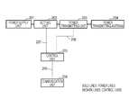
- Fig. 2 is a diagram illustrating a configuration of a power transmitting apparatus.
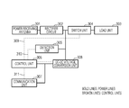
- Fig. 3 is a diagram illustrating a configuration of a power receiving apparatus.
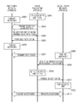
- Fig. 4 is a sequence diagram of the wireless power transmission system.
- Fig. 5 is a flowchart of the power receiving apparatus.
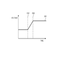
- Fig. 6 is a diagram illustrating a voltage waveform detected by a detection unit of the power receiving apparatus.
- the power transmitting apparatus may, at least temporarily, enter an overcurrent state.
- the power transmitting apparatus limits a current input to the power transmitting unit as in PTL 1
- the first power receiving apparatus becomes unable to receive power at a desired power level, whereby the power transmission efficiency of the whole system will decrease.
- Fig. 1 is a diagram illustrating the configuration of a wireless power transmission system in the present embodiment.
- the magnetic resonance method is a method in which power is transmitted by means of magnetic resonance coupling between a resonator (resonant element) of a power transmitting apparatus and a resonator (resonant element) of a power receiving apparatus.
- a wireless power transmission system non-contact power transmission method
- a power transmission method using electromagnetic induction, electric field resonance, microwaves, a laser, light, or the like may be used.
- reference numeral 101 denotes a power transmitting apparatus
- reference numeral 102 denotes a first power receiving apparatus
- reference numeral 103 denotes a second power receiving apparatus.
- Fig. 2 illustrates the configuration of the power transmitting apparatus 101.
- reference numeral 201 denotes a power supply unit that is connected to a battery of the power transmitting apparatus 101 or to an external power supply and that supplies power to the whole apparatus.
- Reference numeral 202 denotes a setting unit that sets an upper limit for the power transmitted by the power transmitting apparatus 101.
- the setting unit 202 limits an input voltage applied to the power transmitting unit 203 so that transmitted power does not exceed the set upper limit.
- the power transmitting unit 203 converts AC or DC power input from the setting unit 202 into AC power with a frequency in a transmission band, and transmits it to a power receiving apparatus through a power transmitting antenna 204.
- Reference numeral 205 denotes a control unit that controls constituent units of the power transmitting apparatus 101.
- the control unit 205 which is formed of a central processing unit (CPU), performs power transmission processing through control of hardware components by executing stored control programs.
- Reference numeral 206 denotes a communication unit for wireless communication.
- the communication unit 206 sends and receives control signals for wireless power transmission to and from a power receiving apparatus.
- the communication unit 206 has a communication function conforming to, for example, the Bluetooth (registered trade mark) 4.0 specification. Note that the communication unit 206 may use other communication standards, which include, for example, a wireless LAN (IEEE 802.11 series) and Near-Field Communication (NFC).
- IEEE 802.11 series IEEE 802.11 series
- NFC Near-Field Communication
- Reference numeral 207 denotes a control line for communicating control signals between the control unit 205 and the setting unit 202.
- Reference numeral 208 denotes a control line for communicating control signals between the control unit 205 and the power transmitting unit 203.
- Reference numeral 209 denotes a control line for communicating control signals between the control unit 205 and the communication unit 206.
- reference numeral 301 denotes a power receiving antenna for wirelessly receiving power from the power transmitting apparatus 101.
- Reference numeral 302 denotes a rectifier circuit for rectifying AC power received by the power receiving antenna 301 to obtain DC power.
- Reference numeral 303 denotes a load unit that operates with the received power.
- the load unit 303 may be, for example, a battery.
- Reference numeral 304 denotes a switch unit that switches connection between the rectifier circuit 302 and the load unit 303 on and off. The switch unit 304 switches a connection state between the power receiving antenna 301 and the load unit 303 from an unconnected state to a connected state.
- Reference numeral 305 denotes a detection unit that detects a voltage between the rectifier circuit 302 and the switch unit 304.
- Reference numeral 306 denotes a control unit that controls constituent units of the power receiving apparatus.
- the control unit 306 operates using power received through the power receiving antenna 301.
- Reference numeral 307 denotes a communication unit for wireless communication.
- the communication unit 307 sends and receives control signals for wireless power transmission to and from the power transmitting apparatus.
- the communication unit 307 operates using power received through the power receiving antenna 301.
- the communication unit 307 sends a message requesting power transmission together with the amount of requested power to the power transmitting apparatus.
- the communication unit 307 has a communication function conforming to, for example, the Bluetooth (registered trade mark) 4.0 specification.
- the communication unit 307 may use other communication standards, which include, for example, a wireless LAN (IEEE 802.11 series) and Near-Field Communication (NFC).
- Reference numeral 308 denotes a DC-DC voltage conversion unit that converts the output of the rectifier circuit 302 into a voltage allowing the control unit 306 and the communication unit 307 to operate.
- Reference numeral 309 denotes a control line for communicating control signals between the control unit 306 and the switch unit 304
- reference numeral 310 denotes a control line for communicating control signals between the control unit 306 and the detection unit 305.
- Reference numeral 311 denotes a control line for communicating control signals between the control unit 306 and the communication unit 307.
- Fig. 4 is a sequence diagram for the apparatuses in the wireless power transmission system of the present embodiment.
- the power transmitting apparatus 101 sets transmission power to an initially set transmission power (S401).
- the initially set transmission power is 6 W.
- the control unit 205 of the power transmitting apparatus 101 sets 6 W in the setting unit 202.
- the power transmitting unit 203 starts to transmit power for authentication necessary for the control unit 306 and the communication unit 307 to operate (S403).
- the first power receiving apparatus 102 after starting to operate, turns off the switch unit 304, thereby making the rectifier circuit 302 and the load unit 303 be disconnected from each other (S402).
- the first power receiving apparatus 102 when placed on the power transmitting apparatus 101, receives power for authentication, and supplies the received power to the control unit 306 and the communication unit 307.
- the first power receiving apparatus 102 notifies the power transmitting apparatus 101 of a request for authentication using the communication unit 307 (S404).
- the request for authentication can be said to be a message requesting the power transmitting apparatus to transmit power.
- Request for authentication includes the amount of power requested to be transmitted. Note that a notification of the requested power may be sent at the same time as a request for authentication or after completion of the authentication. It is assumed for ease of explanation that power requested by the first power receiving apparatus 102 is 5 W and that a notification of a request for power is sent at the same time as the request for authentication.
- the control unit 205 of the power transmitting apparatus 101 upon receipt of a request for authentication from a power receiving apparatus via the communication unit 206, performs authentication.
- the power transmission and reception apparatuses communicate information regarding supported specifications for wireless power transmission to determine whether or not there are mutually corresponding specifications for wireless power transmission therebetween, and authentication is performed on the basis of the communicated information.
- the power transmitting and receiving apparatuses communicate information regarding respective powers that can be transmitted and received therebetween to determine whether or not the powers that can be respectively transmitted and received by them correspond to each other, and authentication is performed on the basis of the communicated information.
- the power transmitting and receiving apparatuses communicate information for negotiation regarding power to be transmitted and received therebetween, and authentication is performed on the basis of the communicated information.
- the power transmitting apparatus 101 determines whether or not power transmission in accordance with the requested power can be performed under the current setting of the output upper limit. In this example, when 5 W is requested by the first power receiving apparatus 102 under an output upper limit of 6 W, it is determined that power transmission in accordance with the requested power can be performed under the current setting of the output upper limit. When it is determined that power transmission in accordance with the requested power cannot be performed under the current setting of the output upper limit, the output upper limit is re-set. Note that when the request for power received from the power receiving apparatus exceeds the capability of the power transmitting apparatus, rejection of authentication is transmitted to the power receiving apparatus.
- the control unit 205 of the power transmitting apparatus 101 determines whether or not authentication is successful, and when it is determined that the authentication is successful, sends a power reception permission notification to the first power receiving apparatus 102 via the communication unit 206 as a response to the request for authentication (S405). Note that, when the authentication fails, the power transmitting apparatus 101 sends an authentication rejection notification as a response to the request for authentication.
- the first power receiving apparatus 102 upon receipt of a power reception permission notification in response to the request for authentication, makes the switch unit 304 be in a connected state, determining that a modification of a transmission power output in response to the requested power has been detected (S406). It can be said that the power reception permission notification is information for instructing switching of the switch unit 304 to a connected state.
- the first power receiving apparatus 102 receives power transmitted from the power transmitting apparatus 101 and supplies the received power to the load unit 303 (S407).
- the second power receiving apparatus 103 starts a power receiving operation.
- the second power receiving apparatus 103 after starting to operate, turns off the switch unit 304, thereby making the rectifier circuit 302 and the load unit 303 be disconnected from each other (S408).
- the second power receiving apparatus 103 when placed on the power transmitting apparatus 101, receives part of the power being transmitted from the power transmitting apparatus 101, supplies the received power to the control unit 306 and the communication unit 307.
- the second power receiving apparatus 103 notifies the power transmitting apparatus 101 of a request for authentication using the communication unit 307 (S409).
- the power transmitting apparatus 101 determines whether or not authentication for the second power receiving apparatus 103 is successful.
- the power transmitting apparatus 101 also determines whether or not power transmission in accordance with the received request for power can be performed under the current setting of an output upper limit. In this example, since 5 W of power is being transmitted to the first power receiving apparatus 102 under an output upper limit of 6 W, when 5 W of power requested by the second power receiving apparatus 103 is added, the output upper limit is exceeded.
- the power transmitting apparatus 101 When it is determined that power transmission in accordance with the received request for power cannot be performed under the current setting of an output upper limit, the power transmitting apparatus 101 re-sets the current output upper limit (S410). In this case, the control unit 306 of the power transmitting apparatus 101 changes the setting in the setting unit 202 to a value (for example, 12 W) that allows a total of 10 W of power to be transmitted. Note that a notification of power reception termination is sent to the second power receiving apparatus 103 (S410).
- the power transmitting apparatus 101 may send a notification message to the power receiving apparatus, which requested power transmission, instructing not to start control for switching the switch unit 304 to a connected state.
- the control unit 205 of the power transmitting apparatus 101 when transmission of requested power became possible by re-setting performed in the setting unit 202, sends a power reception permission notification to the second power receiving apparatus 103 via the communication unit 307 (S411).
- the second power receiving apparatus 103 upon receipt of the power reception permission notification, makes the switch unit 304 be in a connected state (S412). Then the power transmitting apparatus 101 starts power transmission also for the second power receiving apparatus 103, and the second power receiving apparatus 103 starts to receive 5 W of power from the power transmitting apparatus 101 (S413). Note that the power transmitting apparatus 101 periodically monitors the power transmission output and determines whether or not the set upper limit is appropriate.
- the transmission power becomes less than or equal to a threshold corresponding to the output upper limit, it is checked whether or not any power receiving apparatuses exist using the communication unit 206. Then re-setting is performed to lower the output upper limit in accordance with the power receiving apparatus that has been determined to exist. This processing corresponds to the case in which a power receiving apparatus has been unexpectedly removed. Note that the power transmitting apparatus may perform re-setting to lower the output upper limit upon receipt of a power reception termination message from a power receiving apparatus.
- a power receiving apparatus connects a power receiving antenna to a load circuit upon receipt of a power reception permission notification from a power transmitting apparatus.
- the occurrence of the power transmitting apparatus entering an overcurrent state is decreased since power receiving apparatuses start to increase power consumption in synchronization with the start of output of the power transmitting apparatus in consideration of power transmission to a new power receiving apparatus.
- the power transmitting apparatus does not enter an overcurrent state, the occurrence of power transmission being stopped or output power being reduced is decreased, and the occurrence of power transmission efficiency being reduced in an apparatus which is already receiving power is decreased.
- the power receiving apparatus after starting to operate (S601), turns off the switch unit 304 and disconnects the rectifier circuit 302 from the load unit 303 (S602). Upon receipt of power through the power receiving antenna 301, supplies the received power to the control unit 306 and the communication unit 307. Then, the control unit 306 sends an authentication request including requested power to be supplied by the power transmitting apparatus to the power transmitting apparatus via the communication unit 307 (S603).
- the control unit 306 determines whether or not authentication performed by the power transmitting apparatus is successful on the basis of receipt of a notification of permission or a notification of failed authentication via the communication unit 307 (S604). When the authentication fails, the processing ends. When the authentication is successful, the control unit 306 through control of the communication unit 307, connects the rectifier circuit 302 and the load unit 303 to each other, and starts to supply received power to the load unit 303 (S605, S606). The control unit 306 determines whether or not power reception is to be terminated (S607). When it is determined that power reception is to be terminated, the control unit 306 sends a termination notification to the power transmitting apparatus and terminates the processing (S608, S609). Alternatively, the switch unit 304 may be turned off prior to the termination of the processing. With this operation, processing in step S602 can be omitted in the next power reception processing.
- the power receiving apparatus may start to receive power by detecting a change in the transmission power of the power transmitting apparatus.
- the power receiving apparatus may turn on the switch unit 304 on the basis of the detection result obtained by the detection unit 305 of the second power receiving apparatus 103.
- reference numeral 701 denotes the detection result obtained by the detection unit 305 versus time.
- reference numeral 702 denotes a point of time at which the power transmitting apparatus 101 starts to increase the power transmission output in response to a request from the power receiving apparatus.
- the detection unit 305 detects that the voltage has started to increase.
- the voltage detected by the voltage detection unit 305 increases and stabilizes.
- the detection unit 305 detecting the increase in the voltage and stabilization of the voltage, it can be determined that the power transmitting apparatus 101 has changed the output upper limit.
- An exemplary case in which the control unit 306 and the communication unit 307 of the second power receiving apparatus 103 operate at 5 V and 20 mA will be described. Since the control unit 306 and the communication unit 307 of the second power receiving apparatus 103 consume 20 mA, when the power transmitting apparatus 101 increases the output by 5 W, the voltage detected by the detection unit 305 increases to 250 V.
- a configuration may be employed in which, when the voltage detected by the detection unit 305 becomes 250 V, it is determined that the changing of the output upper limit has been finished in the power transmitting apparatus 101, and reception of 5 W of power from the power transmitting apparatus 101 is started by controlling and turning on the switch unit 304.
- a configuration may be employed in which, a period of time in which the power transmitting apparatus 101 is supposed to change the output upper limit is set and the second power receiving apparatus 103 starts to receive power after the predetermined period of time has elapsed.
- Embodiments of the present invention can also be realized by a computer of a system or apparatus that reads out and executes computer executable instructions recorded on a storage medium (e.g., non-transitory computer-readable storage medium) to perform the functions of one or more of the above-described embodiment of the present invention, and by a method performed by the computer of the system or apparatus by, for example, reading out and executing the computer executable instructions from the storage medium to perform the functions of one or more of the above-described embodiment(s).
- the computer may comprise one or more of a central processing unit (CPU), micro processing unit (MPU), or other circuitry, and may include a network of separate computers or separate computer processors.
- the computer executable instructions may be provided to the computer, for example, from a network or the storage medium.
- the storage medium may include, for example, one or more of a hard disk, a random-access memory (RAM), a read only memory (ROM), a storage of distributed computing systems, an optical disk (such as a compact disc (CD), digital versatile disc (DVD), or Blu-ray Disc (BD) TM ), a flash memory device, a memory card, and the like.
Landscapes
- Engineering & Computer Science (AREA)
- Power Engineering (AREA)
- Computer Networks & Wireless Communication (AREA)
- Charge And Discharge Circuits For Batteries Or The Like (AREA)
Abstract
Description
Claims (11)
- A power receiving apparatus comprising:
a requesting unit configured to request power from a power transmitting apparatus;
a detection unit configured to detect that the power transmitting apparatus has started transmission of the power requested by the requesting unit;
an antenna configured to receive power wirelessly transmitted from the power transmitting apparatus;
a load unit configured to operate using the power received through the antenna; and
a switching unit configured to switch, in accordance with detection performed by the detection unit, a disconnected state in which the antenna and the load unit are disconnected from each other to a connected state in which the antenna and the load unit are connected to each other. - The power receiving apparatus according to Claim 1, wherein the detection performed by the detection unit is performed on a basis of a response from the power transmitting apparatus to a request made by the requesting unit.
- The power receiving apparatus according to Claim 1, wherein the detection performed by the detection unit is performed on a basis of a voltage of an output of a rectifier circuit connected to the antenna.
- The power receiving apparatus according to Claim 1, wherein the requesting unit transmits a message requesting power transmission including an amount of requested power.
- The power receiving apparatus according to Claim 1, wherein the request made by the requesting unit is made using wireless communication.
- The power receiving apparatus according to Claim 1, wherein the request made by the requesting unit is made using power received through the antenna.
- The power receiving apparatus according to Claim 1, wherein the switching unit, when power reception is to be terminated, switches the connected state in which the antenna and the load unit are connected to each other to the disconnected state in which the antenna and the load unit are disconnected from each other.
- The power receiving apparatus according to Claim 1, wherein the load unit is not capable of operating in the disconnected state.
- The power receiving apparatus according to Claim 1, wherein, in the connected state, the load unit operates using the power received through the antenna.
- A control method of controlling a power receiving apparatus comprising:
requesting power from a power transmitting apparatus;
detecting that the power transmitting apparatus has started transmission of the requested power; and
switching, in accordance with the detecting, a state in which an antenna configured to receive power wirelessly transmitted from the power transmitting apparatus and a load unit configured to operate using the power received through the antenna are disconnected from each other to a state in which the antenna and the load unit are connected to each other. - A program causing the power receiving apparatus to execute the control method according to Claim 10.
Priority Applications (3)
| Application Number | Priority Date | Filing Date | Title |
|---|---|---|---|
| GB1603753.3A GB2532401A (en) | 2013-08-09 | 2014-07-18 | Power receiving apparatus |
| US14/910,239 US20160190871A1 (en) | 2013-08-09 | 2014-07-18 | Power receiving apparatus, method of controlling power receiving apparatus, and program |
| CN201480045114.6A CN105453378B (en) | 2013-08-09 | 2014-07-18 | Power receiving equipment |
Applications Claiming Priority (2)
| Application Number | Priority Date | Filing Date | Title |
|---|---|---|---|
| JP2013-166398 | 2013-08-09 | ||
| JP2013166398A JP6300465B2 (en) | 2013-08-09 | 2013-08-09 | Power receiving device, power receiving device control method, and program |
Publications (1)
| Publication Number | Publication Date |
|---|---|
| WO2015019560A1 true WO2015019560A1 (en) | 2015-02-12 |
Family
ID=51453786
Family Applications (1)
| Application Number | Title | Priority Date | Filing Date |
|---|---|---|---|
| PCT/JP2014/003833 Ceased WO2015019560A1 (en) | 2013-08-09 | 2014-07-18 | Power receiving apparatus |
Country Status (5)
| Country | Link |
|---|---|
| US (1) | US20160190871A1 (en) |
| JP (1) | JP6300465B2 (en) |
| CN (1) | CN105453378B (en) |
| GB (1) | GB2532401A (en) |
| WO (1) | WO2015019560A1 (en) |
Cited By (1)
| Publication number | Priority date | Publication date | Assignee | Title |
|---|---|---|---|---|
| EP3136545A1 (en) * | 2015-08-25 | 2017-03-01 | Funai Electric Co., Ltd. | Wireless power transfer to a plurality of receivers |
Families Citing this family (8)
| Publication number | Priority date | Publication date | Assignee | Title |
|---|---|---|---|---|
| JP6590497B2 (en) | 2015-03-18 | 2019-10-16 | キヤノン株式会社 | Power transmission device, control method performed by power transmission device, power reception device, control method performed by power reception device, and program |
| JP6648497B2 (en) * | 2015-11-16 | 2020-02-14 | 船井電機株式会社 | Power supply device and power supply method |
| EP3403313B1 (en) | 2016-01-13 | 2019-05-15 | Koninklijke Philips N.V. | Wireless inductive power transfer |
| JP6953143B2 (en) * | 2017-02-23 | 2021-10-27 | キヤノン株式会社 | Wireless power receiving and power supply systems, power supply devices, electronic devices, control methods and programs |
| JP7121521B2 (en) * | 2018-04-06 | 2022-08-18 | キヤノン株式会社 | Power receiving device, power transmitting device, wireless power transmission system, and control method thereof |
| JP7005423B2 (en) * | 2018-04-27 | 2022-02-04 | キヤノン株式会社 | Power receiving device, power transmission device, wireless power transmission system, power receiving device control method, power transmission device control method and program |
| JP7141238B2 (en) * | 2018-04-27 | 2022-09-22 | キヤノン株式会社 | Power transmission device, control method, and program |
| CN112910112B (en) * | 2019-11-19 | 2024-08-16 | 青岛海尔智能技术研发有限公司 | Method and device for wireless power supply and wireless power supply system |
Citations (4)
| Publication number | Priority date | Publication date | Assignee | Title |
|---|---|---|---|---|
| US20070103110A1 (en) * | 2005-10-24 | 2007-05-10 | Samsung Electronics Co., Ltd. | Apparatus and method of wirelessly sharing power by inductive method |
| US20090001932A1 (en) * | 2007-06-29 | 2009-01-01 | Seiko Epson Corporation | Power transmission control device, power transmission device, non-contact power transmission system, and electronic instrument |
| US20100066305A1 (en) * | 2006-11-08 | 2010-03-18 | Panasonic Corporation | Contactless battery charger, electronic device, battery pack, and contactless charging system |
| JP2013102666A (en) | 2011-10-21 | 2013-05-23 | Sony Corp | Power-feed device and power-feed system |
Family Cites Families (13)
| Publication number | Priority date | Publication date | Assignee | Title |
|---|---|---|---|---|
| JP4308858B2 (en) * | 2007-02-16 | 2009-08-05 | セイコーエプソン株式会社 | Power transmission control device, power reception control device, non-contact power transmission system, power transmission device, power reception device, and electronic equipment |
| JP4725664B2 (en) * | 2008-06-25 | 2011-07-13 | セイコーエプソン株式会社 | Power transmission control device, power transmission device, power reception control device, power reception device, electronic device, power transmission control method, and power reception control method |
| JP2010104203A (en) * | 2008-10-27 | 2010-05-06 | Seiko Epson Corp | Power feed control apparatus, power feed apparatus, electric power-receiving control apparatus, electric power-receiving apparatus, electronic equipment, and contactless power transmission system |
| BR112012025873A2 (en) * | 2010-04-13 | 2016-06-28 | Fujitsu Ltd | power supply system, power transmitter and power receiver |
| CN103119829B (en) * | 2010-10-01 | 2016-01-06 | 松下知识产权经营株式会社 | Electric vehicle power supply system and electric vehicle and power supply device used for the system |
| US9219378B2 (en) * | 2010-11-01 | 2015-12-22 | Qualcomm Incorporated | Wireless charging of devices |
| JP5869759B2 (en) * | 2010-11-04 | 2016-02-24 | キヤノン株式会社 | Wireless power transmission system, wireless power transmission system control method, wireless power transmission device, wireless power transmission device control method, and program |
| CN103348563A (en) * | 2011-02-17 | 2013-10-09 | 松下电器产业株式会社 | Power transmitting apparatus, power receiving apparatus, and power transmitting method |
| KR20130006326A (en) * | 2011-07-07 | 2013-01-16 | 삼성전자주식회사 | Wireless power transmission and charging system, power control and communication method of wireless power transmission and charging system |
| KR101817194B1 (en) * | 2011-08-31 | 2018-01-10 | 삼성전자주식회사 | Wireless power transmission system using solar cell module |
| JP2013132120A (en) * | 2011-12-21 | 2013-07-04 | Nakayo Telecommun Inc | Beyond wall wireless power supply adapter |
| JP6032900B2 (en) * | 2012-02-06 | 2016-11-30 | キヤノン株式会社 | Electronics |
| KR20140031780A (en) * | 2012-09-05 | 2014-03-13 | 삼성전자주식회사 | Wireless power transmitter for excluding cross connected wireless power receiver and method for controlling thereof |
-
2013
- 2013-08-09 JP JP2013166398A patent/JP6300465B2/en active Active
-
2014
- 2014-07-18 CN CN201480045114.6A patent/CN105453378B/en active Active
- 2014-07-18 GB GB1603753.3A patent/GB2532401A/en not_active Withdrawn
- 2014-07-18 US US14/910,239 patent/US20160190871A1/en not_active Abandoned
- 2014-07-18 WO PCT/JP2014/003833 patent/WO2015019560A1/en not_active Ceased
Patent Citations (4)
| Publication number | Priority date | Publication date | Assignee | Title |
|---|---|---|---|---|
| US20070103110A1 (en) * | 2005-10-24 | 2007-05-10 | Samsung Electronics Co., Ltd. | Apparatus and method of wirelessly sharing power by inductive method |
| US20100066305A1 (en) * | 2006-11-08 | 2010-03-18 | Panasonic Corporation | Contactless battery charger, electronic device, battery pack, and contactless charging system |
| US20090001932A1 (en) * | 2007-06-29 | 2009-01-01 | Seiko Epson Corporation | Power transmission control device, power transmission device, non-contact power transmission system, and electronic instrument |
| JP2013102666A (en) | 2011-10-21 | 2013-05-23 | Sony Corp | Power-feed device and power-feed system |
Cited By (4)
| Publication number | Priority date | Publication date | Assignee | Title |
|---|---|---|---|---|
| EP3136545A1 (en) * | 2015-08-25 | 2017-03-01 | Funai Electric Co., Ltd. | Wireless power transfer to a plurality of receivers |
| US20170063162A1 (en) * | 2015-08-25 | 2017-03-02 | Funai Electric Co., Ltd. | Power supply apparatus |
| CN106487106A (en) * | 2015-08-25 | 2017-03-08 | 船井电机株式会社 | Electric supply installation |
| US10367375B2 (en) | 2015-08-25 | 2019-07-30 | Funai Electric Co., Ltd. | Power supply apparatus |
Also Published As
| Publication number | Publication date |
|---|---|
| US20160190871A1 (en) | 2016-06-30 |
| GB201603753D0 (en) | 2016-04-20 |
| CN105453378A (en) | 2016-03-30 |
| CN105453378B (en) | 2018-10-26 |
| JP2015035911A (en) | 2015-02-19 |
| GB2532401A (en) | 2016-05-18 |
| JP6300465B2 (en) | 2018-03-28 |
Similar Documents
| Publication | Publication Date | Title |
|---|---|---|
| WO2015019560A1 (en) | Power receiving apparatus | |
| US11336124B2 (en) | Method for transmitting signal by wireless power transmitter in wireless charging system, wireless power transmitter and wireless power receiver | |
| JP6588455B2 (en) | How to prevent abnormalities during wireless charging | |
| JP6032900B2 (en) | Electronics | |
| US9997927B2 (en) | Power transmission apparatus, control method of power transmission apparatus, and storage medium | |
| US9985477B2 (en) | Power transmitting apparatus, power receiving apparatus, control methods therefor, program, and computer-readable storage medium | |
| US10063112B2 (en) | Power transmission apparatus, method for controlling power transmission apparatus, and storage medium storing program | |
| CN112421801A (en) | Wireless power transmitter and control method thereof | |
| JP6202854B2 (en) | Power supply device | |
| JP6643041B2 (en) | Power transmission equipment | |
| JP6381304B2 (en) | Electronics | |
| JP6494227B2 (en) | Power supply apparatus, control method, and program | |
| JP2014220944A (en) | Power feeding apparatus, electronic apparatus, and program | |
| CN108575101A (en) | Wireless power control method and device thereof | |
| US11011932B2 (en) | Mouse pad comprising wireless power transmission apparatus and mouse | |
| JP2014183628A (en) | Communication apparatus, control method of the same, and program | |
| WO2014208302A1 (en) | Power transmitting apparatus, control method, and storage medium | |
| US10116355B2 (en) | Power supply apparatus, power receiving apparatus, and control method thereof | |
| JP6685158B2 (en) | Power transmission device, power reception device, control method, and program | |
| US9853500B2 (en) | Power supply apparatus, method, and recording medium | |
| US9973029B2 (en) | Wireless power transmission/reception apparatus | |
| WO2015198568A1 (en) | Power transmission apparatus, control method for power transmission apparatus, and program | |
| JP6168869B2 (en) | Power supply device | |
| KR20160144173A (en) | Method for displaying expected wireless charge time and apparatus therefor | |
| JP2016034209A (en) | Power reception device, power transmission device, power reception device control method, power transmission device control method, and program |
Legal Events
| Date | Code | Title | Description |
|---|---|---|---|
| WWE | Wipo information: entry into national phase |
Ref document number: 201480045114.6 Country of ref document: CN |
|
| 121 | Ep: the epo has been informed by wipo that ep was designated in this application |
Ref document number: 14758176 Country of ref document: EP Kind code of ref document: A1 |
|
| WWE | Wipo information: entry into national phase |
Ref document number: 14910239 Country of ref document: US |
|
| NENP | Non-entry into the national phase |
Ref country code: DE |
|
| ENP | Entry into the national phase |
Ref document number: 201603753 Country of ref document: GB Kind code of ref document: A Free format text: PCT FILING DATE = 20140718 |
|
| 122 | Ep: pct application non-entry in european phase |
Ref document number: 14758176 Country of ref document: EP Kind code of ref document: A1 |
|
| ENPC | Correction to former announcement of entry into national phase, pct application did not enter into the national phase |
Ref country code: GB |