WO2015019477A1 - Rehab system and control method therefor - Google Patents
Rehab system and control method therefor Download PDFInfo
- Publication number
- WO2015019477A1 WO2015019477A1 PCT/JP2013/071570 JP2013071570W WO2015019477A1 WO 2015019477 A1 WO2015019477 A1 WO 2015019477A1 JP 2013071570 W JP2013071570 W JP 2013071570W WO 2015019477 A1 WO2015019477 A1 WO 2015019477A1
- Authority
- WO
- WIPO (PCT)
- Prior art keywords
- training
- subject
- rehabilitation
- menu
- sensor
- Prior art date
Links
- 238000000034 method Methods 0.000 title claims description 13
- 238000012549 training Methods 0.000 claims abstract description 290
- 210000003205 muscle Anatomy 0.000 claims abstract description 84
- 230000000694 effects Effects 0.000 claims description 40
- 230000008859 change Effects 0.000 claims description 9
- 210000003141 lower extremity Anatomy 0.000 claims description 7
- 230000003213 activating effect Effects 0.000 claims 2
- 238000005259 measurement Methods 0.000 description 28
- 238000005452 bending Methods 0.000 description 15
- 210000000323 shoulder joint Anatomy 0.000 description 11
- 210000002310 elbow joint Anatomy 0.000 description 10
- 210000001364 upper extremity Anatomy 0.000 description 10
- 230000003183 myoelectrical effect Effects 0.000 description 6
- 210000000689 upper leg Anatomy 0.000 description 6
- 230000036772 blood pressure Effects 0.000 description 5
- 230000036760 body temperature Effects 0.000 description 5
- 210000000629 knee joint Anatomy 0.000 description 5
- 238000004891 communication Methods 0.000 description 4
- 230000036541 health Effects 0.000 description 4
- 238000012545 processing Methods 0.000 description 4
- 230000003042 antagnostic effect Effects 0.000 description 3
- 210000004394 hip joint Anatomy 0.000 description 3
- 210000002758 humerus Anatomy 0.000 description 3
- 230000008569 process Effects 0.000 description 3
- 244000309466 calf Species 0.000 description 2
- 210000000852 deltoid muscle Anatomy 0.000 description 2
- 238000010586 diagram Methods 0.000 description 2
- 238000005516 engineering process Methods 0.000 description 2
- 210000000245 forearm Anatomy 0.000 description 2
- 230000005021 gait Effects 0.000 description 2
- 210000004247 hand Anatomy 0.000 description 2
- 230000010365 information processing Effects 0.000 description 2
- 210000002414 leg Anatomy 0.000 description 2
- 210000002976 pectoralis muscle Anatomy 0.000 description 2
- 238000011084 recovery Methods 0.000 description 2
- 125000002066 L-histidyl group Chemical group [H]N1C([H])=NC(C([H])([H])[C@](C(=O)[*])([H])N([H])[H])=C1[H] 0.000 description 1
- 206010033799 Paralysis Diseases 0.000 description 1
- 230000001133 acceleration Effects 0.000 description 1
- 230000009471 action Effects 0.000 description 1
- 230000001154 acute effect Effects 0.000 description 1
- 239000000853 adhesive Substances 0.000 description 1
- 230000001070 adhesive effect Effects 0.000 description 1
- 230000032683 aging Effects 0.000 description 1
- 230000008901 benefit Effects 0.000 description 1
- 230000002146 bilateral effect Effects 0.000 description 1
- 238000009530 blood pressure measurement Methods 0.000 description 1
- 208000026106 cerebrovascular disease Diseases 0.000 description 1
- 230000003247 decreasing effect Effects 0.000 description 1
- 230000003631 expected effect Effects 0.000 description 1
- 230000006870 function Effects 0.000 description 1
- 230000005484 gravity Effects 0.000 description 1
- 238000012423 maintenance Methods 0.000 description 1
- 230000007246 mechanism Effects 0.000 description 1
- 230000003340 mental effect Effects 0.000 description 1
- 238000012544 monitoring process Methods 0.000 description 1
- 230000008450 motivation Effects 0.000 description 1
- 201000008482 osteoarthritis Diseases 0.000 description 1
- 210000000062 pectoralis major Anatomy 0.000 description 1
- 210000003314 quadriceps muscle Anatomy 0.000 description 1
- 230000004044 response Effects 0.000 description 1
- 230000035807 sensation Effects 0.000 description 1
- 230000015541 sensory perception of touch Effects 0.000 description 1
- 230000004936 stimulating effect Effects 0.000 description 1
- 230000000638 stimulation Effects 0.000 description 1
- 210000000707 wrist Anatomy 0.000 description 1
Images


Classifications
-
- A—HUMAN NECESSITIES
- A61—MEDICAL OR VETERINARY SCIENCE; HYGIENE
- A61B—DIAGNOSIS; SURGERY; IDENTIFICATION
- A61B5/00—Measuring for diagnostic purposes; Identification of persons
- A61B5/24—Detecting, measuring or recording bioelectric or biomagnetic signals of the body or parts thereof
- A61B5/316—Modalities, i.e. specific diagnostic methods
- A61B5/389—Electromyography [EMG]
- A61B5/395—Details of stimulation, e.g. nerve stimulation to elicit EMG response
-
- A—HUMAN NECESSITIES
- A61—MEDICAL OR VETERINARY SCIENCE; HYGIENE
- A61B—DIAGNOSIS; SURGERY; IDENTIFICATION
- A61B5/00—Measuring for diagnostic purposes; Identification of persons
- A61B5/103—Detecting, measuring or recording devices for testing the shape, pattern, colour, size or movement of the body or parts thereof, for diagnostic purposes
- A61B5/11—Measuring movement of the entire body or parts thereof, e.g. head or hand tremor, mobility of a limb
- A61B5/112—Gait analysis
-
- A—HUMAN NECESSITIES
- A61—MEDICAL OR VETERINARY SCIENCE; HYGIENE
- A61B—DIAGNOSIS; SURGERY; IDENTIFICATION
- A61B2505/00—Evaluating, monitoring or diagnosing in the context of a particular type of medical care
- A61B2505/09—Rehabilitation or training
-
- A—HUMAN NECESSITIES
- A61—MEDICAL OR VETERINARY SCIENCE; HYGIENE
- A61B—DIAGNOSIS; SURGERY; IDENTIFICATION
- A61B5/00—Measuring for diagnostic purposes; Identification of persons
- A61B5/0002—Remote monitoring of patients using telemetry, e.g. transmission of vital signals via a communication network
- A61B5/0015—Remote monitoring of patients using telemetry, e.g. transmission of vital signals via a communication network characterised by features of the telemetry system
- A61B5/0024—Remote monitoring of patients using telemetry, e.g. transmission of vital signals via a communication network characterised by features of the telemetry system for multiple sensor units attached to the patient, e.g. using a body or personal area network
-
- A—HUMAN NECESSITIES
- A61—MEDICAL OR VETERINARY SCIENCE; HYGIENE
- A61B—DIAGNOSIS; SURGERY; IDENTIFICATION
- A61B5/00—Measuring for diagnostic purposes; Identification of persons
- A61B5/103—Detecting, measuring or recording devices for testing the shape, pattern, colour, size or movement of the body or parts thereof, for diagnostic purposes
- A61B5/1036—Measuring load distribution, e.g. podologic studies
- A61B5/1038—Measuring plantar pressure during gait
-
- A—HUMAN NECESSITIES
- A61—MEDICAL OR VETERINARY SCIENCE; HYGIENE
- A61B—DIAGNOSIS; SURGERY; IDENTIFICATION
- A61B5/00—Measuring for diagnostic purposes; Identification of persons
- A61B5/103—Detecting, measuring or recording devices for testing the shape, pattern, colour, size or movement of the body or parts thereof, for diagnostic purposes
- A61B5/107—Measuring physical dimensions, e.g. size of the entire body or parts thereof
- A61B5/1071—Measuring physical dimensions, e.g. size of the entire body or parts thereof measuring angles, e.g. using goniometers
-
- A—HUMAN NECESSITIES
- A61—MEDICAL OR VETERINARY SCIENCE; HYGIENE
- A61B—DIAGNOSIS; SURGERY; IDENTIFICATION
- A61B5/00—Measuring for diagnostic purposes; Identification of persons
- A61B5/103—Detecting, measuring or recording devices for testing the shape, pattern, colour, size or movement of the body or parts thereof, for diagnostic purposes
- A61B5/11—Measuring movement of the entire body or parts thereof, e.g. head or hand tremor, mobility of a limb
- A61B5/1113—Local tracking of patients, e.g. in a hospital or private home
- A61B5/1114—Tracking parts of the body
-
- A—HUMAN NECESSITIES
- A61—MEDICAL OR VETERINARY SCIENCE; HYGIENE
- A61B—DIAGNOSIS; SURGERY; IDENTIFICATION
- A61B5/00—Measuring for diagnostic purposes; Identification of persons
- A61B5/103—Detecting, measuring or recording devices for testing the shape, pattern, colour, size or movement of the body or parts thereof, for diagnostic purposes
- A61B5/11—Measuring movement of the entire body or parts thereof, e.g. head or hand tremor, mobility of a limb
- A61B5/1118—Determining activity level
-
- A—HUMAN NECESSITIES
- A61—MEDICAL OR VETERINARY SCIENCE; HYGIENE
- A61B—DIAGNOSIS; SURGERY; IDENTIFICATION
- A61B5/00—Measuring for diagnostic purposes; Identification of persons
- A61B5/22—Ergometry; Measuring muscular strength or the force of a muscular blow
- A61B5/224—Measuring muscular strength
-
- A—HUMAN NECESSITIES
- A61—MEDICAL OR VETERINARY SCIENCE; HYGIENE
- A61B—DIAGNOSIS; SURGERY; IDENTIFICATION
- A61B5/00—Measuring for diagnostic purposes; Identification of persons
- A61B5/24—Detecting, measuring or recording bioelectric or biomagnetic signals of the body or parts thereof
- A61B5/316—Modalities, i.e. specific diagnostic methods
- A61B5/389—Electromyography [EMG]
-
- A—HUMAN NECESSITIES
- A61—MEDICAL OR VETERINARY SCIENCE; HYGIENE
- A61B—DIAGNOSIS; SURGERY; IDENTIFICATION
- A61B5/00—Measuring for diagnostic purposes; Identification of persons
- A61B5/45—For evaluating or diagnosing the musculoskeletal system or teeth
- A61B5/4528—Joints
-
- A—HUMAN NECESSITIES
- A61—MEDICAL OR VETERINARY SCIENCE; HYGIENE
- A61B—DIAGNOSIS; SURGERY; IDENTIFICATION
- A61B5/00—Measuring for diagnostic purposes; Identification of persons
- A61B5/48—Other medical applications
- A61B5/486—Bio-feedback
-
- A—HUMAN NECESSITIES
- A61—MEDICAL OR VETERINARY SCIENCE; HYGIENE
- A61H—PHYSICAL THERAPY APPARATUS, e.g. DEVICES FOR LOCATING OR STIMULATING REFLEX POINTS IN THE BODY; ARTIFICIAL RESPIRATION; MASSAGE; BATHING DEVICES FOR SPECIAL THERAPEUTIC OR HYGIENIC PURPOSES OR SPECIFIC PARTS OF THE BODY
- A61H1/00—Apparatus for passive exercising; Vibrating apparatus ; Chiropractic devices, e.g. body impacting devices, external devices for briefly extending or aligning unbroken bones
- A61H1/02—Stretching or bending or torsioning apparatus for exercising
- A61H1/0237—Stretching or bending or torsioning apparatus for exercising for the lower limbs
- A61H1/024—Knee
-
- A—HUMAN NECESSITIES
- A61—MEDICAL OR VETERINARY SCIENCE; HYGIENE
- A61H—PHYSICAL THERAPY APPARATUS, e.g. DEVICES FOR LOCATING OR STIMULATING REFLEX POINTS IN THE BODY; ARTIFICIAL RESPIRATION; MASSAGE; BATHING DEVICES FOR SPECIAL THERAPEUTIC OR HYGIENIC PURPOSES OR SPECIFIC PARTS OF THE BODY
- A61H1/00—Apparatus for passive exercising; Vibrating apparatus ; Chiropractic devices, e.g. body impacting devices, external devices for briefly extending or aligning unbroken bones
- A61H1/02—Stretching or bending or torsioning apparatus for exercising
- A61H1/0237—Stretching or bending or torsioning apparatus for exercising for the lower limbs
- A61H1/0244—Hip
-
- A—HUMAN NECESSITIES
- A61—MEDICAL OR VETERINARY SCIENCE; HYGIENE
- A61H—PHYSICAL THERAPY APPARATUS, e.g. DEVICES FOR LOCATING OR STIMULATING REFLEX POINTS IN THE BODY; ARTIFICIAL RESPIRATION; MASSAGE; BATHING DEVICES FOR SPECIAL THERAPEUTIC OR HYGIENIC PURPOSES OR SPECIFIC PARTS OF THE BODY
- A61H2201/00—Characteristics of apparatus not provided for in the preceding codes
- A61H2201/50—Control means thereof
- A61H2201/5002—Means for controlling a set of similar massage devices acting in sequence at different locations on a patient
-
- A—HUMAN NECESSITIES
- A61—MEDICAL OR VETERINARY SCIENCE; HYGIENE
- A61H—PHYSICAL THERAPY APPARATUS, e.g. DEVICES FOR LOCATING OR STIMULATING REFLEX POINTS IN THE BODY; ARTIFICIAL RESPIRATION; MASSAGE; BATHING DEVICES FOR SPECIAL THERAPEUTIC OR HYGIENIC PURPOSES OR SPECIFIC PARTS OF THE BODY
- A61H2201/00—Characteristics of apparatus not provided for in the preceding codes
- A61H2201/50—Control means thereof
- A61H2201/5058—Sensors or detectors
- A61H2201/5061—Force sensors
-
- A—HUMAN NECESSITIES
- A61—MEDICAL OR VETERINARY SCIENCE; HYGIENE
- A61H—PHYSICAL THERAPY APPARATUS, e.g. DEVICES FOR LOCATING OR STIMULATING REFLEX POINTS IN THE BODY; ARTIFICIAL RESPIRATION; MASSAGE; BATHING DEVICES FOR SPECIAL THERAPEUTIC OR HYGIENIC PURPOSES OR SPECIFIC PARTS OF THE BODY
- A61H2201/00—Characteristics of apparatus not provided for in the preceding codes
- A61H2201/50—Control means thereof
- A61H2201/5058—Sensors or detectors
- A61H2201/5069—Angle sensors
-
- A—HUMAN NECESSITIES
- A61—MEDICAL OR VETERINARY SCIENCE; HYGIENE
- A61H—PHYSICAL THERAPY APPARATUS, e.g. DEVICES FOR LOCATING OR STIMULATING REFLEX POINTS IN THE BODY; ARTIFICIAL RESPIRATION; MASSAGE; BATHING DEVICES FOR SPECIAL THERAPEUTIC OR HYGIENIC PURPOSES OR SPECIFIC PARTS OF THE BODY
- A61H2201/00—Characteristics of apparatus not provided for in the preceding codes
- A61H2201/50—Control means thereof
- A61H2201/5058—Sensors or detectors
- A61H2201/5084—Acceleration sensors
-
- A—HUMAN NECESSITIES
- A61—MEDICAL OR VETERINARY SCIENCE; HYGIENE
- A61H—PHYSICAL THERAPY APPARATUS, e.g. DEVICES FOR LOCATING OR STIMULATING REFLEX POINTS IN THE BODY; ARTIFICIAL RESPIRATION; MASSAGE; BATHING DEVICES FOR SPECIAL THERAPEUTIC OR HYGIENIC PURPOSES OR SPECIFIC PARTS OF THE BODY
- A61H2201/00—Characteristics of apparatus not provided for in the preceding codes
- A61H2201/50—Control means thereof
- A61H2201/5097—Control means thereof wireless
-
- A—HUMAN NECESSITIES
- A61—MEDICAL OR VETERINARY SCIENCE; HYGIENE
- A61H—PHYSICAL THERAPY APPARATUS, e.g. DEVICES FOR LOCATING OR STIMULATING REFLEX POINTS IN THE BODY; ARTIFICIAL RESPIRATION; MASSAGE; BATHING DEVICES FOR SPECIAL THERAPEUTIC OR HYGIENIC PURPOSES OR SPECIFIC PARTS OF THE BODY
- A61H3/00—Appliances for aiding patients or disabled persons to walk about
Definitions
- the present invention relates to a rehabilitation system and a control method thereof, and more particularly, to a wearable power assist system and a control method thereof for performing rehabilitation by attaching a sensor or device to a person.
- rehabilitation includes acute or convalescent rehabilitation that hospitalized patients receive in hospitals and life stage rehabilitation (maintenance rehabilitation) that continues after discharge.
- Various devices and systems have been proposed according to rehabilitation in each period.
- Patent Document 1 proposes a walking assist system for patients with osteoarthritis.
- a walking assist device having a drive unit and a link mechanism is attached to both feet of a patient, a walking pattern is generated based on a change in the pressure of the sole detected by the foot sensor of the patient, and the walking is performed.
- Walking assistance is provided by controlling the drive unit of the walking assistance device according to the pattern.
- Patent Document 1 discloses a system that recommends a training protocol to a patient remotely, advances training, and monitors the patient's training state to adjust the protocol.
- Patent Document 1 corrects a walking pattern in accordance with an operation instruction from a user who is a doctor, and assists or corrects walking of a patient with a walking assist device based on the walking pattern.
- Patent Document 2 discloses a system that remotely supports a patient by providing a rehabilitation protocol recommendation or a modified protocol to the patient, but suggests that the training content is updated to the optimal training content in real time according to the training effect. There is no.
- An object of the present invention is to allow a subject to perform rehabilitation training based on a training menu and update the training menu based on the body movement of the subject to continuously perform rehabilitation training.
- the present invention also provides rehabilitation training by attaching a sensor that detects muscle movement and physical condition information to the subject's body, and stimulates the muscle part that inhibits the body movement to ensure proper use of the muscle. It is possible to instruct.
- Another object of the present invention is to make it possible to visualize and confirm the movement of a subject who performs training.
- the rehabilitation system according to the present invention is preferably an input terminal that can be operated by a subject who performs rehabilitation training, A display terminal for displaying information on rehabilitation training for the subject; A sensor that is attached to the body of the subject and detects the movement of muscles of the body; A storage unit for storing a training menu in which the content of training is determined in advance for each target person; The training menu for each target person is output from the storage unit, displayed on the display terminal used by the target person, and the data measured by the sensor is the value determined in advance in the training menu.
- An analysis system unit for the target person for judging whether or not The subject analysis system unit is Further, when it is determined that the data measured by the sensor is insufficient with respect to a value predetermined in the training menu, the training menu is changed, and the changed training menu is stored in the storage unit, And the training menu after this change is displayed on this display terminal, and it is comprised as a rehabilitation system characterized by performing rehabilitation training based on the training menu after this change.
- the rehabilitation system according to the present invention is also preferably an input terminal that can be operated by a subject who performs rehabilitation training, A display terminal for displaying information on rehabilitation training for the subject; A sensor that is attached to the body of the subject and detects the movement of the muscles of the body; a feedback device that provides a stimulus to the body part of the subject; A storage unit for storing a training menu in which the content of training is determined in advance for each target person; From the storage unit, the training menu for each subject is output and displayed on the display terminal used by the subject. And when it is judged that the data measured by the sensor is insufficient with respect to a predetermined value in the training menu, an analysis system unit for a target person that activates the feedback device, It is comprised as a rehabilitation system characterized by having.
- the rehabilitation control method according to the present invention is preferably configured as a rehabilitation control method in the rehabilitation system.
- the present invention or, preferably, a rehabilitation training wearing device to be worn by a subject of rehabilitation training, A plurality of sensors for detecting the joint angle and muscle movement of the subject's body; A sensor for detecting physical condition information of the subject; A feedback device that emits a signal that stimulates the muscle portion of the subject that is estimated to be a factor that hinders the goal of rehabilitation training; It is configured as a rehabilitation training wearing device in which a wireless unit that transmits a signal detected by the sensor to the outside and transmits a signal transmitted from the outside to the feedback device is arranged.
- ADVANTAGE OF THE INVENTION it becomes possible to make a subject perform rehabilitation training based on a training menu, update a training menu based on a body motion of a subject, and perform rehabilitation training continuously.
- a sensor that detects muscle movement and physical condition information is attached to the subject's body and rehabilitation training is performed, and stimulation is given to the muscle portion that inhibits the movement of the body to instruct the proper use of the muscle. Is possible.
- FIG. 1 shows the configuration of a rehabilitation training system according to the first embodiment.
- the rehabilitation training system is configured by connecting information processing apparatuses at each base of a hospital 2, a day care center rehabilitation facility 3, and a plurality of patient homes 4 to a data center 1 via a network.
- the data center 1 is constructed by one or a plurality of servers, and includes a patient analysis system 11, a facility analysis system 12, a doctor analysis system 14, a PHR (Personal Health Record) 13, and a database (abbreviated as DB). 15.
- the patient analysis system 11, the facility analysis system 12, and the doctor analysis system 14 execute their specific application programs on a server to realize their functions.
- the PHR 13 is a record corresponding to the patient's individual electronic medical record, and is stored in the DB 13.
- the DB 15 stores various information necessary for rehabilitation training including the PHR 13.
- An information processing apparatus such as an input terminal 43 and a display terminal 44 and a wireless unit 45 are installed in the patient house 4.
- the patient P1 wears the sensing wear 42 and performs rehabilitation training according to the guidance displayed on the display terminal 44.
- the sensing wear 42 is provided with a plurality of sensors 422, a feedback (FB) device 423, and a wireless unit 421 for transmitting and receiving data to and from the wireless unit 45.
- the plurality of sensors 422 detect and measure rehabilitation motion information related to movement of joint angles of each joint, muscle activity information related to surface myoelectric potential and muscle hardness, and physical condition information such as body temperature, pulse, blood pressure, and the like in real time. .
- the configuration of the sensing wear 42 will be described later with reference to FIG.
- the FB device 423 is a device that stimulates a portion of a patient's muscle that is estimated to be a factor that hinders a training target by vibration, pressure contact, or the like, and is activated in response to an instruction from the patient analysis system 11.
- the sensing wear 42 is called in this way because it is equipped with various sensors, but it may be simply called training wear.
- the patient analysis system 11 corresponds to an external device (or simply external) when viewed from the sensing wear 42.
- the patient P1 can input a message or the like to the doctor during training by using the input terminal 43. Information input from the input terminal 43 is recorded in the PHR 13.
- the patient analysis system 11 compares the sensor measurement values (muscle movement and physical condition information) of the sensing wear 42 with the target training information recorded in the PHR 13 for each patient, and changes the training as necessary.
- the information regarding the comparison result and the training change is transmitted to the display terminal 44 of the patient house 4 and displayed.
- a signal for stimulating the patient's muscle portion may be called a warning signal
- the data is transmitted to the feedback device 423 through the wireless unit 45 and the wireless unit 421 of the sensing wear 42.
- the feedback device 423 gives a stimulus to the patient's muscles based on the received warning signal to call attention.
- All the information processed by the patient analysis system 11 (including information input from the patient terminal input terminal 43) is recorded in the PHR 13.
- the PHR 13 is connected to the doctor analysis system 14, the facility analysis system 12, and the DB 15, and the information recorded in the PHR 13 is anonymized and stored in the DB 15.
- the doctor analysis system 14 creates the doctor general information including the message input from the input terminal 43 by the patient P1 after the training based on the training information recorded in the PHR 13.
- the created doctor general information is temporarily stored in the DB 15.
- the doctor P3 of the hospital 2 can instruct from the input terminal 24, access the DB 15, read the doctor general information, and display it on the display terminal 23. Based on this information, the doctor P3 can input the training content of the next day from the input terminal 24 to the doctor analysis system 14.
- the training content consists of several types of training menus, and the training menus are composed of training patterns.
- the training menu and training pattern will be described later with reference to FIGS.
- the training menu refers to a series of training operations such as “shoulder and elbow rehabilitation training” and “rehabilitation training of muscles around the shoulder joint”.
- the training pattern is a basic unit of the operation that constitutes the training menu. For example, “stretch both arms so that the right and left shoulder flexion angles and left and right elbow flexion angles are 0 degrees, 45 degrees to 90 degrees, and 0 degrees, respectively”. Or a basic unit of training operation such as “bend both arms so that the right and left shoulder flexion angles and left and right elbow flexion angles are 90 degrees, 0 degrees to 0 degrees, and 45 degrees, respectively”.
- the doctor P3 can search the DB 15 from the search terminal 22 as a reference for determining the next rehabilitation training, and can obtain information on the training content effective for the person with the same medical condition.
- the facility analysis system 12 is connected to a display terminal 32 installed in a day care center rehabilitation facility (hereinafter simply referred to as a rehabilitation facility) 3 that performs care and rehabilitation such as a day care center in the vicinity of the patient's home 4.
- the facility analysis system 12 displays physical condition information and warning information on the display terminal 32 when the physical information such as body temperature, pulse, blood pressure changes suddenly during the training of the patient P1 based on the information recorded in the PHR 13.
- the staff P2 of the rehabilitation facility 3 looks at the display information on the display terminal 32 and determines whether to “call the patient's home 4”, “directly to the patient's home 4”, or “contact the hospital 2”.
- the facility analysis system 12 analyzes not only the emergency situation during rehabilitation training, but also the training frequency, and the staff P2 of the rehabilitation facility 3 periodically contacts the patient P1 for patients who are prone to training. Then, the cause of health condition and mental condition is examined and reported to the doctor P3.
- the rehabilitation training system shown in FIG. 1 has the PHR 13 and the patient analysis system 11 in the data center 1, but these can be installed on the patient home 4 side as an alternative.
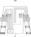
- FIG. 6 shows an example of the configuration of the sensing wear 42.
- the sensing wear 42 is worn when performing shoulder and elbow rehabilitation training.
- the sensing wear 42 may be called training wear.
- Motion sensors 4221 are arranged on the left and right upper arms and forearms of the sensing wear 42
- a pulse wave sensor 4222 is arranged on the left or right wrist.
- a muscle activity measuring sensor 4224 is disposed in a portion corresponding to the upper arm bilateral and upper arm third muscles and a portion corresponding to the shoulder deltoid, great circular and latissimus.
- the location of the pulse wave sensor 4222 is preferably attached to a person that can be easily attached according to the paralyzed hand.
- a device that stimulates the human body with a tactile sensation such as vibration by a vibration motor using a haptic technology is used in the vicinity of the muscle activity measurement sensor 4224 (that is, a muscle region estimated to be a factor that hinders a training target) ).
- the muscle activity measurement sensor 4224 that is, a muscle region estimated to be a factor that hinders a training target.
- These motion sensor 4221, pulse wave sensor 4222, muscle activity measurement sensor 4224, and FB device 423 are connected to the wireless unit 421.
- the motion sensor 4221 includes a three-axis acceleration sensor and a three-axis gyroscope, measures the upper arm and forearm movements, and detects the joint angles of the left and right shoulder joints and elbow joints. It is desirable to fix the motion sensor 4221 to the human body from above the sensing wear 42 with a hook-and-loop belt so that the position attached during training is not displaced.
- the motion measurement can be performed by motion capture using an infrared or visible light camera or posture recognition using a distance camera without mounting the sensing wear 42 incorporating the motion sensor 4221. In this case, it is preferable to keep a large space of about 3 m in front of the camera and the patient.
- the pulse wave sensor 4222 for example, a pulse wave propagation type sphygmomanometer described in Patent Document 3 that detects a blood pressure by detecting a pulse wave can be used. With this method, the heart rate can be measured. Further, the pulse wave sensor 4222 has a built-in thermometer and can also measure the body temperature. The pulse wave sensor 4222 may be a wristwatch-type wearing device different from the sensing wear 42.
- the muscle activity sensor 4224 for example, a small myoelectric sensor described in Patent Literature 4 and Patent Literature 5 can be used.
- the amount of muscle activity depends on the amplitude of the myoelectric signal. That is, the amount of muscle activity corresponds to an envelope when full-wave rectification of the myoelectric signal is performed.
- a muscle hardness meter can also be used for the muscle activity sensor 4224. When measured with a myoelectric sensor, it depends on hardness when measured with a muscle hardness meter.
- it can also be used by directly fixing the sensor to the human body with an adhesive bandage like an electrode of an electrocardiogram.
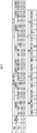
- FIG. 9 shows a data configuration example of the training menu (TM).
- the illustrated example shows a data configuration of an upper limb rehabilitation training menu “shoulder and elbow rehabilitation training” including two training patterns TP1 and TP2. This training menu is recorded in the order of TP1, TP2.
- Each training pattern TP includes a TP number, a maximum required time for training by this training pattern, a joint angle at the start of the training pattern, a joint angle at the end of the training pattern, and data representing right and left.
- the joint angle at the start of the above training pattern is further the rotation angle of the right shoulder joint, abduction angle, horizontal bending angle, bending angle, rotation angle of the left shoulder joint, abduction angle, horizontal bending angle, bending angle, right elbow joint It consists of rotation angle, flexion angle, left elbow joint rotation angle, and flexion angle.
- the rotation angle of the right shoulder joint abduction angle, horizontal bending angle, bending angle, rotation angle of the left shoulder joint, abduction angle, horizontal bending angle, bending angle, rotation angle of the right elbow joint, It consists of a bending angle, a rotation angle of the left elbow joint, and a bending angle.
- the right further includes data on the activity status of the right greater pectoral muscle, deltoid muscle, subscapular muscle, latissimus dorsi, humerus, biceps and humerus.
- the data structure on the left is the same as that on the right.
- the information other than the joint motion angle and muscle activity information focused on in each training pattern TP is NA (Not Applicable) and is not managed.
- the muscle activity information a muscle part predicted to be active in the training menu is represented by “1”, and a muscle part predicted not to be active is represented by “0”.
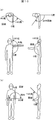
- FIG. 10 is a schematic diagram showing the names of the joint angles.
- FIG. 10A shows the joint angle of the shoulder joint
- FIG. 10B shows the joint angle of the elbow joint.
- the shoulder joint can be expressed by a rotation angle, an abduction angle, a horizontal bending angle, and a bending angle
- the elbow joint can be expressed by a rotation angle and a bending angle. Most of the upper limb movements can be expressed by these angular movements of the shoulder and elbow joints.
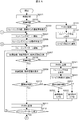
- the overall processing flow will be outlined.
- the patient analysis system 11 displays the training content and the communication items from the doctor on the display terminal 44 (S203).
- the training menu and the target action are displayed on the display terminal 44, and the patient performs training according to the display.
- the patient analysis system 11 always measures exercise parameters including physical condition information, joint angle motion information, and muscle activity information, and displays the motion currently performed by the patient and the target motion on the display terminal 44.
- the patient analysis system 11 constantly determines the physical condition of the patient during the training, and immediately determines that the physical condition of the patient P1 has deteriorated based on the physical condition information (S208 to S242). When it is determined that the physical condition is normal, the patient analysis system 11 determines whether to continue the training without changing the target by combining the measured motion information and muscle information, or to continue the training by changing the target value. It is determined whether to continue the training by changing the information and recorded in the PHR, and an instruction is given to the display device 44 (S209 to S211). At that time, feedback is given to the FB device 423 in order to give a stimulus such as vibration to muscles related to training as necessary (S252, S253).
- the patient analysis system 11 compares the current training result with the past result, and displays the result on the display terminal 44 (S216). The arrival status and history of the final goal are displayed on the display terminal 44 (S217).
- the doctor sends to the analysis system for doctors 14 information that summarizes the reaction to the target and the results for search.
- the patient analysis system 11 further acquires the communication items to the doctor that the patient inputs from the input terminal 43, records them in the PHR 13 and then records them in the DB 15 (S219, S220), and ends the series of training.
- shoulder and elbow rehabilitation training will be described as an example. This rehabilitation training is performed while lying on its back.
- the training menu for “shoulder and elbow rehabilitation training” consists of training pattern 1 (TP1) of “stretching arms from the state of crossing hands over the chest” and “extending the elbows from the state of stretching arms” It consists of training pattern 2 (TP2), “Bringed and assembled hands on chest” and repeats 20 times with TP1 and TP2 as a set.
- the contents of each training pattern are as shown in FIG. In this training pattern, only the left and right shoulder joint flexion angles and the elbow joint flexion angles are managed.
- the patient P1 starts the rehabilitation training in accordance with the training menu displayed on the display terminal 44 by wearing the sensing wear 42 in the patient house 4 (S206).
- physical condition information is measured and physical condition determination is made as to whether it is within the reference value (S207, S208). For example, if the patient's body temperature is in the range of 36 to 37 degrees, the maximum blood pressure is in the range of 120-140 mmHg, the minimum blood pressure is in the range of 60-90 mmHg, and the pulse is between 60-100 times per minute Judge that the physical condition is normal. Although these values are standard values, the normal range of the patient's physical condition information is preset for each patient and recorded in the PHR 13.
- the patient analysis system 11 determines that the physical condition is poor, records physical condition information in the PHR 13 (S241), and displays on the display terminal 44 that the training is stopped (S242). Further, the fact that the patient's health condition is not normal is displayed on the display terminal 32 of the rehabilitation facility 3 via the facility analysis system 12. As a result of the physical condition determination, when it is determined that the physical condition is normal (S208 / Yes), the training contents and the communication items determined by the doctor P3 are displayed on the display terminal 44 (S209), and the training menu is started.
- the operation of the current training menu is first displayed as an animation on the display terminal 44, and the expected effect will be described.
- the training pattern TP1 is started.
- a plurality of sensors 422 (4221 to 4224) provided in the sensing wear 42 measure the patient's body temperature information, joint angle motion, and muscle activity information, and measure each time.
- Data is transmitted to the patient analysis system 11 via the wireless units 421 and 45. Measurement and judgment of physical condition information is given the highest priority even during training, and when it exceeds the normal range, the training is immediately stopped and notified and displayed on the display terminal 32 of the rehabilitation facility 3.
- the patient analysis system 11 animates the target training operation (target operation) according to the training pattern of the training menu and the actually measured patient motion.
- the information is displayed on the display terminal 44 (S209).
- FIG. 1 An example of a screen displayed on the display terminal 44 during training is shown in FIG.
- a person is represented by a simplified model
- the target upper limb movement is represented by a dotted line
- the measured upper limb movement is represented by a solid line.
- the patient performs rehabilitation training so that the solid line that is his / her movement overlaps the dotted line which is the target movement.
- the measured physical condition information is displayed in a scale on the lower side of the display screen.
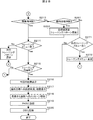
- the joint angle judgment 1 is performed from the joint angle data of the patient's upper limbs actually measured (S210).
- the joint angle determination 1 it is determined whether the current training pattern is suitable in view of each joint motion of the patient.
- the judgment method is to estimate the target angle of each joint angle when measuring the joint angle data of the patient's upper limb by linear interpolation from the joint angle data at the start and end of the training pattern and the maximum required time. Judge by comparing with the actual measurement.
- Judgment of each joint angle is performed by comparing the ratio of the actual measurement value to the target angle of each joint operation angle with a preset threshold value. It is suitable when the ratio of the actually measured operation angle to the target operation angle is larger than the threshold value.
- the target motion angle is the absolute value obtained by subtracting the target angle at the start of the training pattern from the target angle at the time of joint angle data measurement.
- the actual operation angle is the actual angle at the start of the training pattern subtracted from the actual angle at the time of joint angle data measurement. Absolute value. As an example, FIG.
- FIG. 11 shows an example of a target angle, an actual measurement angle, a target operation angle, an actual operation angle, a ratio of the actual operation angle to the target operation angle, and a threshold value of the joint angle 2 seconds after the training pattern 1 is started.
- the threshold value since all the operations are equal to or greater than the threshold value, Yes is determined.
- the left elbow movement (0.56) is smaller than the threshold value (0.65), so it is determined No. If it is determined Yes, the measurement result is recorded in the PHR 13 (S211).
- the patient analysis system 11 determines No in the joint angle determination 1, the patient analysis system 11 performs a muscle activity determination 1 (S251).
- the muscle activity determination from the muscle activity information of the patient, it is determined from the training pattern information and the measured muscle activity information whether the muscle strength is weak and the target movement is not possible or whether the antagonistic muscle is strong and the target movement is not possible. to decide.
- the training pattern it is expected from FIG. 9 that the greater pectoral muscle, the deltoid muscle, and the triceps are active, and the latissimus dorsi, the upper arm, and the biceps are not active.
- the latissimus dorsi, humerus and biceps are not active from the actually measured muscle activity information, it is determined that the pectoralis major, triceps, and triceps are weak, that is, Yes.
- the latissimus dorsi muscle, the upper arm muscles, and the biceps brachii muscles are active, it is determined that the antagonistic muscles are engaged and the target movement is not performed, that is, No.
- joint angle determination 2 it is determined whether or not the current training pattern needs to be changed as seen from each joint motion of the patient (S213).
- the target motion angle of each joint angle at the end of the training pattern is compared with the measured motion angle, and when the measured motion angle is close to the target motion angle, Yes is set, and when it is far away, No is set.
- the ratio of the actually measured value of the joint operation angle to the target angle is compared with a preset threshold value.
- the joint angle determination 2 is Yes, the training pattern content is not changed, and the process proceeds to the training menu end determination (S214).
- the joint angle determination 2 is No, the muscle activity determination 2 is performed (S261).
- the muscle activity determination 2 it is determined whether or not the muscle activity necessary for the executed training pattern has occurred (S261). The case where the muscle activity necessary for the training pattern can be actually measured is set to Yes, and the case where the muscle activity cannot be measured is set to No. If the result of muscle activity determination 2 is Yes, the target joint angle is updated so that the numerical value of the training pattern can be easily achieved (S262).
- the renewal constant is determined in advance by the doctor depending on the recovery state of the patient, but about 0.1-0.3 is often appropriate.
- the training pattern used for estimating the target operating angle here is not the training pattern with the child number updated during training, but the training pattern set first.
- the training pattern After the training pattern is updated, it is determined whether the current training menu is completed, that is, whether the setting of TP1 and TP2 is repeated 20 times (S214). If the training menu has not ended, the next training pattern is selected and the training pattern loop is repeated (S281, S206 to S213). When the training menu is finished, it is determined whether the training content is finished (S215). If the training content has not ended, the next training menu is selected and the training menu loop is repeated (S204 to S214). When the training content is completed, the patient analysis system 11 transmits the result of the current training to the display terminal 44 and displays it.
- the muscles necessary to perform the executed training pattern are not active, and the current training menu is not valid for the current state of the patient.
- the current training menu is canceled and it is determined whether there is a next training menu (S271). If there is, the training menu is changed to (S272). If there is no next training menu, it is determined that the training content has been completed, and the current result is displayed on the display terminal 44 (S216).
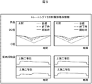
- the patient's home 4 is displayed by displaying the current training result (before and after training) and the comparison result with the past result on the display terminal 44.
- the training result of this time is performed by sending data of time-series changes of each joint angle, joint angular velocity, and muscle activity information to the display terminal 23 together.
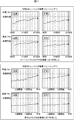
- FIG. 4 shows an example of a screen displayed on the patient terminal display terminal 44 after the training is completed.
- the past state and the state of the current training result can be compared with quantitative values such as the bending angle of the joint angle, so it is easy to grasp the slight training effect and maintain motivation for rehabilitation training. it can.
- an image in which the movement of the patient is reproduced by an instruction from the input terminal 24 is displayed.
- An example of a screen displayed on the display terminal 23 that reports to the doctor after the end of training is shown in FIG.
- the doctor reports the details of the rehabilitation training such as the joint angle during training and the time series information of the muscle activity at that time.
- a message (communication matter) from the patient to the doctor is acquired (S218), recorded in the PHR 13 for each patient (S219), and further stored in the DB 15 (S220), and a series of rehabilitation. End training.
- Example 2 describes a lower limb rehabilitation training system for correcting a gait of a patient who can walk to some extent.
- the difference between the lower limb rehabilitation training system and the upper limb habilitation training system described in Example 1 is that instead of sensing wear, which is an upper limb motion measurement system, the patient has to equip the lower limb motion measurement system with equipment It is to wear and train.
- the training state was judged by the joint angle of the shoulder joint and elbow joint and the amount of activity of the muscle that moves it, but in the lower limb motion measurement system, the joint angle of the hip joint and knee joint and the activity of the muscle that moves it. The training state is judged by the amount.
- FIG. 7 shows a configuration example of the lower limb motion measurement system.
- (A) is a configuration of the entire system
- (b) is a configuration of a joint angle measuring device
- (c) is a configuration of an insole type sole pressure measuring device for shoes.
- the lower limb motion measurement system includes a joint angle measurement device 71, a plantar pressure measurement device 72, a feedback (FB) device 73, and a muscle activity sensor.
- the muscle activity sensor is not shown because it is attached to the skin.
- the FB device 73 has the same configuration as the FB 423 shown in FIG.
- the data measured by the joint angle measuring device 71, the plantar pressure measuring device 72, and the muscle activity sensor are transmitted to the wireless unit 45 via the wireless unit 421 of the sensing wear 42 as in the first embodiment, and are analyzed for the patient. Sent to the system 11. As a result of the data processing performed by the patient analysis system 11, an instruction signal is sent to the FB device 73 via the wireless unit 45 and the wireless unit 421.
- the joint angle measuring device 71 includes two stays 714, stays 715, a single-axis angle measuring sensor 716, an inertial movement sensor unit 717, and a belt for fixing the stay 714 to the upper thigh. 718, a belt 719 for fixing the stay 715 to the lower leg, and a uniaxial slider 713.
- the stay 714 and the stay 715 have a link structure in which end portions are jointed, and a one-axis angle measurement sensor 716 is attached to the joint portion, and an inertial movement sensor unit 717 is attached to the stay 714.
- the 1-axis angle measurement sensor 716 and the inertial movement sensor unit 717 are connected to the wireless unit 421.
- the angle of the knee joint is measured by the uniaxial angle measurement sensor 716, and the angle of the hip joint is measured by the inertial movement sensor unit 717.
- a potentiometer, a rotary encoder, or the like is used as the uniaxial angle measurement sensor 716.
- the stay 714 is completely fixed to the upper leg by a belt 718, but the stay 715 is fixed to the lower leg by a belt 719 via a one-axis slider 713 so that the stay 715 can move in the longitudinal direction of the lower leg.
- the knee joint angle is not an ideal uniaxial rotary joint, and the central axis moves depending on the bending angle. Therefore, even if the central axis moves, the stay 715 moves in the longitudinal direction of the lower leg. This is because the structure allows measurement (see FIG. 8).
- the plantar pressure measuring device 72 has a structure in which a plurality of pressure sensitive sensors 722 are fixed to an insole 721 of a shoe. The position and number of the pressure sensitive sensors 722 can be changed as necessary. As shown in FIG. 7C, it is desirable to provide at least five pressure-sensitive sensors 722 because weight shift and left / right balance can be measured.
- the data measured by the plantar pressure measuring device 72 is not used for resetting or feedback of the real-time training target value, but is important information for the doctor to analyze the movement of the center of gravity during walking after training.
- the FB device 73 is fixed to the thigh and calf with an upper thigh fixing belt 718 and a lower thigh fixing belt 719.
- the human body can be stimulated by the FB device 73 of the thigh, and when it is better to increase the flexion angle of the knee joint, the human body can be stimulated by the FB device 73 of the calf.
- the FB device 73 uses a feedback device such as a vibration motor using a haptic technology that gives a stimulus to a human body by tactile sense, as in the upper limb motion measurement system of the first embodiment.
- the muscle activity sensor is fixed with a bandage at a position where, for example, the iliopsoas muscle, the gluteal muscle, the hamstring, and the quadriceps muscle can be measured.
- Data center 11 Patient analysis system 12: Facility analysis system 13: PHR (Personal Health Record) 14: Analysis system for doctors 15: DB 2: Hospital 22: Search terminal 23: Display terminal 24: Input terminal 3: Day care center rehabilitation facility 32: Display terminal 4: Patient home 42: Sensing wear 421: Wireless unit 422: Sensor 423: FB equipment 43: Input terminal 44: Display terminal 45: Wireless unit
Abstract
The present invention performs rehab training continuously by having the subject perform rehab training on the basis of a training menu and updating the training menu on the basis of the subject's body movements. The rehab system comprises: a sensor, which is installed on a rehab subject's body and is for detecting movements of a muscle of the body; a storage unit for storing training menus for each subject in which training details are set forth beforehand; and a subject analysis system unit for outputting each subject's training menu from the storage unit and displaying same on the display terminal being used by the subject, and for determining whether or not the data measured by the sensor is adequate with respect to the value previously set forth in the training menu. When it is determined that the data measured by the sensor is inadequate with respect to the value previously set forth in the training menu, the subject analysis system unit updates the training menu, displays the updated training menu on the display terminal, and has the subject perform rehab training on the basis of the updated training menu.
Description
本発明は、リハビリシステム及びその制御方法に係り、特に人にセンサや機器を装着してリハビリテーションを行う、装着型パワーアシストシステムおよびその制御方法に関する。
The present invention relates to a rehabilitation system and a control method thereof, and more particularly, to a wearable power assist system and a control method thereof for performing rehabilitation by attaching a sensor or device to a person.
リハビリテーション(以下単にリハビリという)には、入院患者が病院で受ける急性期ないし回復期リハビリと、退院後に続ける生活期リハビリ(維持期リハビリ)がある。各期のリハビリに応じて種々の装置やシステムが提案されている。
Rehabilitation (hereinafter simply referred to as rehabilitation) includes acute or convalescent rehabilitation that hospitalized patients receive in hospitals and life stage rehabilitation (maintenance rehabilitation) that continues after discharge. Various devices and systems have been proposed according to rehabilitation in each period.
例えば、高齢化による体力や筋力の低下した人のために、補助機器や器具を患者に装着してリハビリテーションを行う装置が提案されている。特許文献1には、変形性関節症の患者のための歩行アシストシステムが提案されている。このシステムは、駆動ユニットとリンク機構部を有する歩行補助装置を患者の両足に装着して、患者の足底センサにより検出された足底の圧力の変化に基づいて歩行パターンを生成してその歩行パターンに従って歩行補助装置の駆動ユニットを制御することにより歩行補助するものである。
For example, a device has been proposed for performing rehabilitation by attaching an auxiliary device or instrument to a patient for a person whose physical strength and muscle strength have decreased due to aging. Patent Document 1 proposes a walking assist system for patients with osteoarthritis. In this system, a walking assist device having a drive unit and a link mechanism is attached to both feet of a patient, a walking pattern is generated based on a change in the pressure of the sole detected by the foot sensor of the patient, and the walking is performed. Walking assistance is provided by controlling the drive unit of the walking assistance device according to the pattern.
また、遠隔監視によるリハビリテーションシステムに関して、例えば特許文献1には、遠隔で患者にトレーニングプロトコルを推薦してトレーニングを進め、患者のトレーニング状態を監視してプロトコルを調節するシステムが開示されている。
Further, regarding a rehabilitation system using remote monitoring, for example, Patent Document 1 discloses a system that recommends a training protocol to a patient remotely, advances training, and monitors the patient's training state to adjust the protocol.
特許文献1は、医師であるユーザからの操作指示に従って歩行パターンを修正して、歩行パターンに基づいて歩行補助装置で患者の歩行を補助ないし矯正するものである。特許文献2には、リハビリテーションプロトコルの推薦又はその修正したプロトコルを患者に提供して遠隔で支援するシステムが開示されているが、トレーニング効果に応じてリアルタイムに最適なトレーニング内容に更新する旨の示唆はない。
Patent Document 1 corrects a walking pattern in accordance with an operation instruction from a user who is a doctor, and assists or corrects walking of a patient with a walking assist device based on the walking pattern. Patent Document 2 discloses a system that remotely supports a patient by providing a rehabilitation protocol recommendation or a modified protocol to the patient, but suggests that the training content is updated to the optimal training content in real time according to the training effect. There is no.
本発明は、トレーニングメニューに基づいて対象者にリハビリトレーニングを行わせ、対象者の体の動きに基づいてトレーニングメニューを更新してリハビリトレーニングを継続的に行うようにすることにある。
本発明はまた、筋肉の動きや体調情報を検知するセンサを対象者の体に装着してリハビリトレーニングを行い、体の動きを阻害している筋肉部分に刺激を与えて適正な筋肉の使い方を指示することを可能とする。
本発明はまた、トレーニングを行う対象者の動きを可視化して確認できるようにすることにある。 An object of the present invention is to allow a subject to perform rehabilitation training based on a training menu and update the training menu based on the body movement of the subject to continuously perform rehabilitation training.
The present invention also provides rehabilitation training by attaching a sensor that detects muscle movement and physical condition information to the subject's body, and stimulates the muscle part that inhibits the body movement to ensure proper use of the muscle. It is possible to instruct.
Another object of the present invention is to make it possible to visualize and confirm the movement of a subject who performs training.
本発明に係るリハビリシステムは、好ましくは、リハビリトレーニングを行う対象者が操作することができる入力端末と、
該対象者のためにリハビリトレーニングに関する情報を表示する表示端末と、
該対象者の体に装着される、該体の筋肉の動きを検知するセンサと、
該対象者ごとに予めトレーニングの内容を定めたトレーニングメニューを記憶する記憶部と、
該記憶部から、該対象者ごとの該トレーニングメニューを出力して、該対象者が用いる該表示端末に表示し、かつ該センサによって計測されたデータが、該トレーニングメニューで予め定めた値に対して十分か否かを判断する対象者用解析システム部と、を有し、
前記対象者用解析システム部は、
更に、該センサによって計測されたデータが、該トレーニングメニューで予め定めた値に対して不十分と判断した場合、該トレーニングメニューを変更して、該変更したトレーニングメニューを該記憶部に記憶し、かつ
該変更後のトレーニングメニューを該表示端末に表示して、該変更後のトレーニングメニューに基づいてリハビリトレーニングを行わせる、ことを特徴とするリハビリシステムとして構成される。 The rehabilitation system according to the present invention is preferably an input terminal that can be operated by a subject who performs rehabilitation training,
A display terminal for displaying information on rehabilitation training for the subject;
A sensor that is attached to the body of the subject and detects the movement of muscles of the body;
A storage unit for storing a training menu in which the content of training is determined in advance for each target person;
The training menu for each target person is output from the storage unit, displayed on the display terminal used by the target person, and the data measured by the sensor is the value determined in advance in the training menu. An analysis system unit for the target person for judging whether or not
The subject analysis system unit is
Further, when it is determined that the data measured by the sensor is insufficient with respect to a value predetermined in the training menu, the training menu is changed, and the changed training menu is stored in the storage unit, And the training menu after this change is displayed on this display terminal, and it is comprised as a rehabilitation system characterized by performing rehabilitation training based on the training menu after this change.
本発明に係るリハビリシステムはまた、好ましくは、リハビリトレーニングを行う対象者が操作することができる入力端末と、
該対象者のためにリハビリトレーニングに関する情報を表示する表示端末と、
該対象者の体に装着される、該体の筋肉の動きを検知するセンサと、該対象者の体の部位に刺激を与えるフィードバック機器と、
該対象者ごとに予めトレーニングの内容を定めたトレーニングメニューを記憶する記憶部と、
該記憶部から、該対象者ごとの該トレーニングメニューを出力して、該対象者が用いる該表示端末に表示し、
かつ該センサによって計測されたデータが、該トレーニングメニューで予め定めた値に対して不十分と判断した場合、該フィードバック機器を起動する対象者用解析システム部と、
を有することを特徴とするリハビリシステムとして構成される。 The rehabilitation system according to the present invention is also preferably an input terminal that can be operated by a subject who performs rehabilitation training,
A display terminal for displaying information on rehabilitation training for the subject;
A sensor that is attached to the body of the subject and detects the movement of the muscles of the body; a feedback device that provides a stimulus to the body part of the subject;
A storage unit for storing a training menu in which the content of training is determined in advance for each target person;
From the storage unit, the training menu for each subject is output and displayed on the display terminal used by the subject.
And when it is judged that the data measured by the sensor is insufficient with respect to a predetermined value in the training menu, an analysis system unit for a target person that activates the feedback device,
It is comprised as a rehabilitation system characterized by having.
本発明に係るリハビリ制御方法は、好ましくは、上記リハビリシステムにおけるリハビリ制御方法として構成される。
The rehabilitation control method according to the present invention is preferably configured as a rehabilitation control method in the rehabilitation system.
本発明または、好ましくは、リハビリトレーニングの対象者に装着されるリハビリトレーニング用装着具であって、
対象者の体の関節角及び筋肉の可動状況を検知する複数センサと、
該対象者の体調情報を検知するセンサと、
リハビリトレーニングの目標を阻害する要因と推定される対象者の筋肉の部分に刺激を与える信号を発するフィードバック機器と、
該センサで検知された信号を外部に送信し、かつ外部から送信される信号を該フィードバック機器に伝える無線ユニットを配置した、リハビリトレーニング用装着具として構成される。 The present invention or, preferably, a rehabilitation training wearing device to be worn by a subject of rehabilitation training,
A plurality of sensors for detecting the joint angle and muscle movement of the subject's body;
A sensor for detecting physical condition information of the subject;
A feedback device that emits a signal that stimulates the muscle portion of the subject that is estimated to be a factor that hinders the goal of rehabilitation training;
It is configured as a rehabilitation training wearing device in which a wireless unit that transmits a signal detected by the sensor to the outside and transmits a signal transmitted from the outside to the feedback device is arranged.
本発明によれば、トレーニングメニューに基づいて対象者にリハビリトレーニングを行わせ、対象者の体の動きに基づいてトレーニングメニューを更新してリハビリトレーニングを継続的に行うことが可能となる。
また、筋肉の動きや体調情報を検知するセンサを対象者の体に装着してリハビリトレーニングを行い、体の動きを阻害している筋肉部分に刺激を与えて適正な筋肉の使い方を指示することが可能となる。また、トレーニングを行う対象者の動きを可視化して確認することができる。 ADVANTAGE OF THE INVENTION According to this invention, it becomes possible to make a subject perform rehabilitation training based on a training menu, update a training menu based on a body motion of a subject, and perform rehabilitation training continuously.
In addition, a sensor that detects muscle movement and physical condition information is attached to the subject's body and rehabilitation training is performed, and stimulation is given to the muscle portion that inhibits the movement of the body to instruct the proper use of the muscle. Is possible. In addition, it is possible to visualize and confirm the movement of the subject performing the training.
図1は実施例1によるリハビリトレーニングシステムの構成を示す。
リハビリトレーニングシステムは、病院2、デイケアセンタリハビリ施設3、複数の患者宅4の各拠点にある情報処理装置がネットワークを介して、データセンタ1に接続して構成される。データセンタ1は、1又は複数のサーバによって構築され、患者用解析システム11と、施設用解析システム12と、医師用解析システム14と、PHR(Personal Health Record)13、及びデータベース(DBと略す)15を有して構成される。患者用解析システム11と、施設用解析システム12と、医師用解析システム14は、特有のアプリケーションプログラムをサーバで実行してそれらの機能が実現される。PHR13は患者個人の電子カルテに相当する記録であり、それぞれDB13に記憶される。DB15は、PHR13をはじめとしてリハビリトレーニングに必要な種々の情報を記憶する。 FIG. 1 shows the configuration of a rehabilitation training system according to the first embodiment.
The rehabilitation training system is configured by connecting information processing apparatuses at each base of ahospital 2, a day care center rehabilitation facility 3, and a plurality of patient homes 4 to a data center 1 via a network. The data center 1 is constructed by one or a plurality of servers, and includes a patient analysis system 11, a facility analysis system 12, a doctor analysis system 14, a PHR (Personal Health Record) 13, and a database (abbreviated as DB). 15. The patient analysis system 11, the facility analysis system 12, and the doctor analysis system 14 execute their specific application programs on a server to realize their functions. The PHR 13 is a record corresponding to the patient's individual electronic medical record, and is stored in the DB 13. The DB 15 stores various information necessary for rehabilitation training including the PHR 13.
リハビリトレーニングシステムは、病院2、デイケアセンタリハビリ施設3、複数の患者宅4の各拠点にある情報処理装置がネットワークを介して、データセンタ1に接続して構成される。データセンタ1は、1又は複数のサーバによって構築され、患者用解析システム11と、施設用解析システム12と、医師用解析システム14と、PHR(Personal Health Record)13、及びデータベース(DBと略す)15を有して構成される。患者用解析システム11と、施設用解析システム12と、医師用解析システム14は、特有のアプリケーションプログラムをサーバで実行してそれらの機能が実現される。PHR13は患者個人の電子カルテに相当する記録であり、それぞれDB13に記憶される。DB15は、PHR13をはじめとしてリハビリトレーニングに必要な種々の情報を記憶する。 FIG. 1 shows the configuration of a rehabilitation training system according to the first embodiment.
The rehabilitation training system is configured by connecting information processing apparatuses at each base of a
患者宅4には、入力端末43及び表示端末44などの情報処理装置と、無線ユニット45が設置される。このような構成において、患者P1はセンシングウェア42を装着して表示端末44に表示される案内に従ってリハビリトレーニングを行う。センシングウェア42には複数のセンサ422と、フィードバック(FB)機器423と、無線ユニット45との間でデータ送受信するための無線ユニット421が設けられている。複数のセンサ422は例えば、各関節の関節角の動きに関するリハビリ動作情報や、表面筋電位や筋肉硬さに関する筋肉活動情報や、体温、脈拍、血圧などの体調情報をリアルタイムに検知して計測する。(なお、センシングウェア42の構成については図6を参照して後述する。)
リハビリトレーニング中にセンサ422で計測されたデータは無線ユニット421より無線ユニット45へ送信される。無線ユニット45に送信されたデータはデータセンタ1にある患者用解析システム11へ送信される。FB機器423は、振動や圧接等によってトレーニングの目標を阻害する要因と推定される患者の筋肉の部分に刺激を与える機器であり、患者用解析システム11からの指示に応じて起動される。なお、センシングウェア42は種々のセンサを装備しているのでこのように呼んでいるが、単にトレーニングウェアと呼んでもよい。また、患者用解析システム11はセンシングウェア42から見れば外部装置(或いは単に外部)に相当する。
患者P1は入力端末43によってトレーニングにおける医師への伝言等を入力することができる。入力端末43から入力された情報はPHR13に記録される。 An information processing apparatus such as aninput terminal 43 and a display terminal 44 and a wireless unit 45 are installed in the patient house 4. In such a configuration, the patient P1 wears the sensing wear 42 and performs rehabilitation training according to the guidance displayed on the display terminal 44. The sensing wear 42 is provided with a plurality of sensors 422, a feedback (FB) device 423, and a wireless unit 421 for transmitting and receiving data to and from the wireless unit 45. For example, the plurality of sensors 422 detect and measure rehabilitation motion information related to movement of joint angles of each joint, muscle activity information related to surface myoelectric potential and muscle hardness, and physical condition information such as body temperature, pulse, blood pressure, and the like in real time. . (The configuration of the sensing wear 42 will be described later with reference to FIG. 6).
Data measured by thesensor 422 during rehabilitation training is transmitted from the wireless unit 421 to the wireless unit 45. The data transmitted to the wireless unit 45 is transmitted to the patient analysis system 11 in the data center 1. The FB device 423 is a device that stimulates a portion of a patient's muscle that is estimated to be a factor that hinders a training target by vibration, pressure contact, or the like, and is activated in response to an instruction from the patient analysis system 11. The sensing wear 42 is called in this way because it is equipped with various sensors, but it may be simply called training wear. The patient analysis system 11 corresponds to an external device (or simply external) when viewed from the sensing wear 42.
The patient P1 can input a message or the like to the doctor during training by using theinput terminal 43. Information input from the input terminal 43 is recorded in the PHR 13.
リハビリトレーニング中にセンサ422で計測されたデータは無線ユニット421より無線ユニット45へ送信される。無線ユニット45に送信されたデータはデータセンタ1にある患者用解析システム11へ送信される。FB機器423は、振動や圧接等によってトレーニングの目標を阻害する要因と推定される患者の筋肉の部分に刺激を与える機器であり、患者用解析システム11からの指示に応じて起動される。なお、センシングウェア42は種々のセンサを装備しているのでこのように呼んでいるが、単にトレーニングウェアと呼んでもよい。また、患者用解析システム11はセンシングウェア42から見れば外部装置(或いは単に外部)に相当する。
患者P1は入力端末43によってトレーニングにおける医師への伝言等を入力することができる。入力端末43から入力された情報はPHR13に記録される。 An information processing apparatus such as an
Data measured by the
The patient P1 can input a message or the like to the doctor during training by using the
患者用解析システム11は、センシングウェア42のセンサの計測値(筋肉の動きや体調情報)と、患者ごとにPHR13に記録された目標のトレーニング情報とを比較し、必要に応じてトレーニングの変更を行い、比較結果及びトレーニング変更に関する情報を患者宅4の表示端末44へ送信して表示する。また、比較の結果、計測値が目標のトレーニング情報と離れている(許容範囲外)と判断した場合、患者の筋肉の部分に刺激を与えるための信号(警告信号といってもよい)を、無線ユニット45及びセンシングウェア42の無線ユニット421を通してフィードバック機器423へ送信する。フィードバック機器423は、受信した警告信号を基に患者の筋肉の部分に刺激を与えて注意を喚起する。
The patient analysis system 11 compares the sensor measurement values (muscle movement and physical condition information) of the sensing wear 42 with the target training information recorded in the PHR 13 for each patient, and changes the training as necessary. The information regarding the comparison result and the training change is transmitted to the display terminal 44 of the patient house 4 and displayed. In addition, as a result of the comparison, when it is determined that the measured value is different from the target training information (outside the allowable range), a signal for stimulating the patient's muscle portion (may be called a warning signal) The data is transmitted to the feedback device 423 through the wireless unit 45 and the wireless unit 421 of the sensing wear 42. The feedback device 423 gives a stimulus to the patient's muscles based on the received warning signal to call attention.
患者用解析システム11で処理された情報(患者宅の入力端末43から入力された情報も含む)は全てPHR13に記録される。PHR13は、医師用解析システム14と施設用解析システム12およびDB15に接続され、PHR13に記録された情報は匿名化されて、DB15に記憶される。
All the information processed by the patient analysis system 11 (including information input from the patient terminal input terminal 43) is recorded in the PHR 13. The PHR 13 is connected to the doctor analysis system 14, the facility analysis system 12, and the DB 15, and the information recorded in the PHR 13 is anonymized and stored in the DB 15.
医師用解析システム14は、PHR13に記録されたトレーニング情報を基にトレーニング終了後の患者P1が入力端末43から入力した伝言も含めて医師用総括情報を作成する。作成された医師用総括情報はDB15に一旦記憶される。病院2の医師P3は、入力端末24から指示してDB15をアクセスして医師用総括情報を読み出し、それを表示端末23に表示することができる。この情報を基に医師P3は次の日のトレーニング内容を入力端末24から医師解析用システム14に入力することがきる。トレーニング内容は数種類のトレーニングメニューからなり、トレーニングメニューはトレーニングパターンで構成されている。
The doctor analysis system 14 creates the doctor general information including the message input from the input terminal 43 by the patient P1 after the training based on the training information recorded in the PHR 13. The created doctor general information is temporarily stored in the DB 15. The doctor P3 of the hospital 2 can instruct from the input terminal 24, access the DB 15, read the doctor general information, and display it on the display terminal 23. Based on this information, the doctor P3 can input the training content of the next day from the input terminal 24 to the doctor analysis system 14. The training content consists of several types of training menus, and the training menus are composed of training patterns.
トレーニングメニュー及びトレーニングパターンについては、図9~図10を参照して後述する。概略言えば、トレーニングメニューは例えば「肩と肘のリハビリトレーニング」や「肩関節周囲筋のリハビリトレーニング」といった一連のトレーニング動作をいう。トレーニングパターンは、トレーニングメニューを構成する動作の基本単位であり、例えば、「右左肩屈曲角と左右肘屈曲角をそれぞれ0度、45度から90度、0度になるように両腕を伸ばす」や「右左肩屈曲角と左右肘屈曲角をそれぞれ90度、0度から0度、45度になるように両腕を曲げる」などのトレーニング動作の基本単位をいう。トレーニング内容を入力する際、医師P3は、次のリハビリトレーニングを決める参考として、検索端末22よりDB15を検索して、同様の病状の人に効果があったトレーニング内容に関する情報を得ることができる。
The training menu and training pattern will be described later with reference to FIGS. Generally speaking, the training menu refers to a series of training operations such as “shoulder and elbow rehabilitation training” and “rehabilitation training of muscles around the shoulder joint”. The training pattern is a basic unit of the operation that constitutes the training menu. For example, “stretch both arms so that the right and left shoulder flexion angles and left and right elbow flexion angles are 0 degrees, 45 degrees to 90 degrees, and 0 degrees, respectively”. Or a basic unit of training operation such as “bend both arms so that the right and left shoulder flexion angles and left and right elbow flexion angles are 90 degrees, 0 degrees to 0 degrees, and 45 degrees, respectively”. When inputting the training content, the doctor P3 can search the DB 15 from the search terminal 22 as a reference for determining the next rehabilitation training, and can obtain information on the training content effective for the person with the same medical condition.
施設用解析システム12は、患者宅4の近隣にあるデイケアセンタなどの介護とリハビリを行うデイケアセンタリハビリ施設(以下単にリハビリ施設という)3に設置された表示端末32に接続される。施設用解析システム12はPHR13に記録された情報を基に患者P1がトレーニング中に体温、脈拍、血圧といった体調情報が急変した場合、表示端末32に体調情報や警告の情報を表示する。リハビリ施設3の職員P2は表示端末32の表示情報を見て、「患者宅4に電話する」又は「患者宅4に直行する」又は「病院2に連絡する」の判断を行う。また、施設用解析システム12はリハビリトレーニング中の緊急事態だけでなく、トレーニング頻度に関する解析も行い、トレーニングが滞りがちな患者に対しては定期的にリハビリ施設3の職員P2が患者P1に連絡をとり、健康状態や精神状態などその原因を調べて、医師P3に報告する。
なお、図1に示したリハビリトレーニングシステムは、データセンタ1内にPHR13および患者用解析システム11を有しているが、代案としてはこれらを患者宅4側に設置することも可能である。 Thefacility analysis system 12 is connected to a display terminal 32 installed in a day care center rehabilitation facility (hereinafter simply referred to as a rehabilitation facility) 3 that performs care and rehabilitation such as a day care center in the vicinity of the patient's home 4. The facility analysis system 12 displays physical condition information and warning information on the display terminal 32 when the physical information such as body temperature, pulse, blood pressure changes suddenly during the training of the patient P1 based on the information recorded in the PHR 13. The staff P2 of the rehabilitation facility 3 looks at the display information on the display terminal 32 and determines whether to “call the patient's home 4”, “directly to the patient's home 4”, or “contact the hospital 2”. In addition, the facility analysis system 12 analyzes not only the emergency situation during rehabilitation training, but also the training frequency, and the staff P2 of the rehabilitation facility 3 periodically contacts the patient P1 for patients who are prone to training. Then, the cause of health condition and mental condition is examined and reported to the doctor P3.
The rehabilitation training system shown in FIG. 1 has thePHR 13 and the patient analysis system 11 in the data center 1, but these can be installed on the patient home 4 side as an alternative.
なお、図1に示したリハビリトレーニングシステムは、データセンタ1内にPHR13および患者用解析システム11を有しているが、代案としてはこれらを患者宅4側に設置することも可能である。 The
The rehabilitation training system shown in FIG. 1 has the
図6にセンシングウェア42の構成の一例を示す。このセンシングウェア42は肩と肘のリハビリトレーニングを行う場合に装着するものである。なお、センシングウェア42はトレーニングウェアと呼んでもよい。
センシングウェア42の左右の上腕および前腕部分にはモーションセンサ4221が配置され、左あるいは右手首部分には脈波センサ4222が配置される。更に、上腕の上腕二等筋および上腕三等筋に相当する部分と肩の三角筋、大円筋、広背筋に相当する部分には筋肉活動計測センサ4224が配置されている。脈波センサ4222の場所は麻痺手に応じて取り付けやすい方に装着するのがよい。FB機器423としては、ハプティクス技術を用いた振動モータによる振動などの触覚で人体に刺激を与える機器が、筋肉活動計測センサ4224の近傍(即ちトレーニングの目標を阻害する要因と推定される筋肉の部位)に配置されている。これらモーションセンサ4221、脈波センサ4222、筋肉活動計測センサ4224およびFB機器423は無線ユニット421に接続されている。 FIG. 6 shows an example of the configuration of thesensing wear 42. The sensing wear 42 is worn when performing shoulder and elbow rehabilitation training. The sensing wear 42 may be called training wear.
Motion sensors 4221 are arranged on the left and right upper arms and forearms of the sensing wear 42, and a pulse wave sensor 4222 is arranged on the left or right wrist. Further, a muscle activity measuring sensor 4224 is disposed in a portion corresponding to the upper arm bilateral and upper arm third muscles and a portion corresponding to the shoulder deltoid, great circular and latissimus. The location of the pulse wave sensor 4222 is preferably attached to a person that can be easily attached according to the paralyzed hand. As the FB device 423, a device that stimulates the human body with a tactile sensation such as vibration by a vibration motor using a haptic technology is used in the vicinity of the muscle activity measurement sensor 4224 (that is, a muscle region estimated to be a factor that hinders a training target) ). These motion sensor 4221, pulse wave sensor 4222, muscle activity measurement sensor 4224, and FB device 423 are connected to the wireless unit 421.
センシングウェア42の左右の上腕および前腕部分にはモーションセンサ4221が配置され、左あるいは右手首部分には脈波センサ4222が配置される。更に、上腕の上腕二等筋および上腕三等筋に相当する部分と肩の三角筋、大円筋、広背筋に相当する部分には筋肉活動計測センサ4224が配置されている。脈波センサ4222の場所は麻痺手に応じて取り付けやすい方に装着するのがよい。FB機器423としては、ハプティクス技術を用いた振動モータによる振動などの触覚で人体に刺激を与える機器が、筋肉活動計測センサ4224の近傍(即ちトレーニングの目標を阻害する要因と推定される筋肉の部位)に配置されている。これらモーションセンサ4221、脈波センサ4222、筋肉活動計測センサ4224およびFB機器423は無線ユニット421に接続されている。 FIG. 6 shows an example of the configuration of the
モーションセンサ4221は3軸の加速度センサと3軸ジャイロスコープを備えており、上腕および前腕の動作を計測し、左右の肩関節と肘関節の関節角度を検出する。モーションセンサ4221はトレーニング中に取り付けた位置がずれないように面ファスナー式のベルトでセンシングウェア42の上から人体に固定することが望ましい。なお、モーション計測はモーションセンサ4221を内蔵したセンシングウェア42を装着しなくても、赤外、可視光カメラを用いたモーションキャプチャや距離カメラを用いた姿勢認識でも計測可能である。この場合、カメラと患者の前に3m程度の広い空間を保つのがよい。
The motion sensor 4221 includes a three-axis acceleration sensor and a three-axis gyroscope, measures the upper arm and forearm movements, and detects the joint angles of the left and right shoulder joints and elbow joints. It is desirable to fix the motion sensor 4221 to the human body from above the sensing wear 42 with a hook-and-loop belt so that the position attached during training is not displaced. The motion measurement can be performed by motion capture using an infrared or visible light camera or posture recognition using a distance camera without mounting the sensing wear 42 incorporating the motion sensor 4221. In this case, it is preferable to keep a large space of about 3 m in front of the camera and the patient.
脈波センサ4222としては例えば特許文献3に記載の、脈波を検知して血圧を検知する脈波伝播方式の血圧計を使用することができる。この方式では心拍数を計測することができる。さらに脈波センサ4222は温度計を内蔵して体温の計測もできる。また脈波センサ4222はセンシングウェア42とは別の腕時計型の装着デバイスにすることもできる。
As the pulse wave sensor 4222, for example, a pulse wave propagation type sphygmomanometer described in Patent Document 3 that detects a blood pressure by detecting a pulse wave can be used. With this method, the heart rate can be measured. Further, the pulse wave sensor 4222 has a built-in thermometer and can also measure the body temperature. The pulse wave sensor 4222 may be a wristwatch-type wearing device different from the sensing wear 42.
筋肉活動センサ4224としては、例えば特許文献4及び特許文献5に記載の、小型の筋電センサを使用することができる。筋電センサを使用する場合、筋肉活動量は筋電信号の振幅に依存する。すなわち、筋肉活動量は筋電信号を全波整流したときの包絡線に相当する。筋肉活動センサ4224には筋硬度計を使用することもできる。筋電センサで計測した場合は、筋硬度計で計測した場合は硬度に依存する。また、筋電センサを使用する場合、心電図の電極のようにセンサを人体に絆創膏で直接固定して使用することもできる。
As the muscle activity sensor 4224, for example, a small myoelectric sensor described in Patent Literature 4 and Patent Literature 5 can be used. When an electromyographic sensor is used, the amount of muscle activity depends on the amplitude of the myoelectric signal. That is, the amount of muscle activity corresponds to an envelope when full-wave rectification of the myoelectric signal is performed. A muscle hardness meter can also be used for the muscle activity sensor 4224. When measured with a myoelectric sensor, it depends on hardness when measured with a muscle hardness meter. Moreover, when using a myoelectric sensor, it can also be used by directly fixing the sensor to the human body with an adhesive bandage like an electrode of an electrocardiogram.
次に、図9~図10を参照して、トレーニングメニュー及びトレーニングパターンについて説明する。
図9はトレーニングメニュー(TM)のデータ構成例を示す。図示の例は2つのトレーニングパターンTP1、TP2からなる上肢リハビリトレーニングメニュー「肩と肘のリハビリトレーニング」のデータ構成を示している。このトレーニングメニューはTP1、TP2の順に記録される。 Next, a training menu and a training pattern will be described with reference to FIGS.
FIG. 9 shows a data configuration example of the training menu (TM). The illustrated example shows a data configuration of an upper limb rehabilitation training menu “shoulder and elbow rehabilitation training” including two training patterns TP1 and TP2. This training menu is recorded in the order of TP1, TP2.
各トレーニングパターンTPは、TP番号、このトレーニングパターンによるトレーニングにかける最大所要時間、トレーニングパターン開始時の関節角、トレーニングパターン終了時の関節角、右及び左を表すデータから構成される。上記トレーニングパターン開始時の関節角は更に、右肩関節の回旋角、外転角、水平屈曲角、屈曲角、左肩関節の回旋角、外転角、水平屈曲角、屈曲角、右肘関節の回旋角、屈曲角、左肘関節の回旋角、屈曲角から構成される。上記トレーニングパターン終了時は更に、右肩関節の回旋角、外転角、水平屈曲角、屈曲角、左肩関節の回旋角、外転角、水平屈曲角、屈曲角、右肘関節の回旋角、屈曲角、左肘関節の回旋角、屈曲角から構成される。上記右は更に、右の大胸筋、三角筋、肩甲下筋、広背筋、上腕筋、上腕二頭筋、上腕筋の活動状態のデータから構成される。上記左も上記右を同様のデータ構成である。
ここで、各トレーニングパターンTPで着目する関節運動角、筋肉活動情報以外はNA(Not Applicable (適用せずの意味))とし、管理を行わない。筋肉活動情報はトレーニングメニューで活動すると予測される筋肉部位は「1」、活動しないと予測される筋肉部位は「0」で表す。 Each training pattern TP includes a TP number, a maximum required time for training by this training pattern, a joint angle at the start of the training pattern, a joint angle at the end of the training pattern, and data representing right and left. The joint angle at the start of the above training pattern is further the rotation angle of the right shoulder joint, abduction angle, horizontal bending angle, bending angle, rotation angle of the left shoulder joint, abduction angle, horizontal bending angle, bending angle, right elbow joint It consists of rotation angle, flexion angle, left elbow joint rotation angle, and flexion angle. At the end of the training pattern, the rotation angle of the right shoulder joint, abduction angle, horizontal bending angle, bending angle, rotation angle of the left shoulder joint, abduction angle, horizontal bending angle, bending angle, rotation angle of the right elbow joint, It consists of a bending angle, a rotation angle of the left elbow joint, and a bending angle. The right further includes data on the activity status of the right greater pectoral muscle, deltoid muscle, subscapular muscle, latissimus dorsi, humerus, biceps and humerus. The data structure on the left is the same as that on the right.
Here, the information other than the joint motion angle and muscle activity information focused on in each training pattern TP is NA (Not Applicable) and is not managed. In the muscle activity information, a muscle part predicted to be active in the training menu is represented by “1”, and a muscle part predicted not to be active is represented by “0”.
図10は各関節角の名称を表す模式図を示す。図10(a)は肩関節の関節角、図10(b)は肘関節の関節角を示す。肩関節は回旋角、外転角、水平屈曲角、屈曲角で表すことができ、肘関節は回旋角、屈曲角で表すことができる。肩関節及び肘関節のこれら角運動でほとんどの上肢運動を表現することができる。
FIG. 10 is a schematic diagram showing the names of the joint angles. FIG. 10A shows the joint angle of the shoulder joint, and FIG. 10B shows the joint angle of the elbow joint. The shoulder joint can be expressed by a rotation angle, an abduction angle, a horizontal bending angle, and a bending angle, and the elbow joint can be expressed by a rotation angle and a bending angle. Most of the upper limb movements can be expressed by these angular movements of the shoulder and elbow joints.
次に、図2を参照して、リハビリトレーニングシステムにおける処理手順について説明する。
まず全体の処理の流れについて概略説明する。リハビリトレーニングを開始するにあたり、患者の体調を計測してトレーニングを行える状態であるか確認する(S201)。次に患者用解析システム11は、トレーニング内容、医師からの連絡事項を表示端末44に表示する(S203)。次に、トレーニングメニュー及び目標動作を表示端末44に表示し、患者はその表示に従いトレーニングを行う。その際、患者用解析システム11は、常に体調情報および関節角動作情報と筋肉活動情報からなる運動パラメータを計測し、患者が現在行っている動作と目標動作を併せて表示端末44に表示する。患者用解析システム11は、トレーニング中常時患者の体調判断を行っていて、体調情報より患者P1の体調が悪化したと判断した場合、直ちにトレーニングを中止する(S208~S242)。体調が正常と判断した場合、患者用解析システム11は、計測された動作情報と筋肉情報を組み合わせて目標を変えずにトレーニングを継続するか、目標値を変えてトレーニングを継続するか、トレーニング部位を変えてトレーニングを継続するかを判断してPHRに記録して、表示装置44に指示を出す(S209~S211)。その際、必要に応じてトレーニングに関係する筋肉に振動などの刺激を与えるためにFB機器423にフィードバックを与える(S252,S253)。これを最初に設定したトレーニング内容が終了するまで繰り返す(S214,S215)。トレーニング終了後、患者用解析システム11は、今回のトレーニング結果と過去の結果を比較しその結果を表示端末44に表示する(S216)。また最終目標への到達状況および履歴を表示端末44に表示する(S217)。また医師用解析システム14へ医師が検索用の、目標に対する反応と結果をまとめた情報を送る。患者用解析システム11は更に患者が入力端末43から入力する医師への連絡事項を取得して、PHR13に記録しその後DB15に記録して(S219、S220)、一連のトレーニングを終了する。 Next, a processing procedure in the rehabilitation training system will be described with reference to FIG.
First, the overall processing flow will be outlined. When starting rehabilitation training, it is checked whether the patient can be trained by measuring the physical condition of the patient (S201). Next, thepatient analysis system 11 displays the training content and the communication items from the doctor on the display terminal 44 (S203). Next, the training menu and the target action are displayed on the display terminal 44, and the patient performs training according to the display. At that time, the patient analysis system 11 always measures exercise parameters including physical condition information, joint angle motion information, and muscle activity information, and displays the motion currently performed by the patient and the target motion on the display terminal 44. The patient analysis system 11 constantly determines the physical condition of the patient during the training, and immediately determines that the physical condition of the patient P1 has deteriorated based on the physical condition information (S208 to S242). When it is determined that the physical condition is normal, the patient analysis system 11 determines whether to continue the training without changing the target by combining the measured motion information and muscle information, or to continue the training by changing the target value. It is determined whether to continue the training by changing the information and recorded in the PHR, and an instruction is given to the display device 44 (S209 to S211). At that time, feedback is given to the FB device 423 in order to give a stimulus such as vibration to muscles related to training as necessary (S252, S253). This is repeated until the initially set training content is completed (S214, S215). After the training, the patient analysis system 11 compares the current training result with the past result, and displays the result on the display terminal 44 (S216). The arrival status and history of the final goal are displayed on the display terminal 44 (S217). In addition, the doctor sends to the analysis system for doctors 14 information that summarizes the reaction to the target and the results for search. The patient analysis system 11 further acquires the communication items to the doctor that the patient inputs from the input terminal 43, records them in the PHR 13 and then records them in the DB 15 (S219, S220), and ends the series of training.
まず全体の処理の流れについて概略説明する。リハビリトレーニングを開始するにあたり、患者の体調を計測してトレーニングを行える状態であるか確認する(S201)。次に患者用解析システム11は、トレーニング内容、医師からの連絡事項を表示端末44に表示する(S203)。次に、トレーニングメニュー及び目標動作を表示端末44に表示し、患者はその表示に従いトレーニングを行う。その際、患者用解析システム11は、常に体調情報および関節角動作情報と筋肉活動情報からなる運動パラメータを計測し、患者が現在行っている動作と目標動作を併せて表示端末44に表示する。患者用解析システム11は、トレーニング中常時患者の体調判断を行っていて、体調情報より患者P1の体調が悪化したと判断した場合、直ちにトレーニングを中止する(S208~S242)。体調が正常と判断した場合、患者用解析システム11は、計測された動作情報と筋肉情報を組み合わせて目標を変えずにトレーニングを継続するか、目標値を変えてトレーニングを継続するか、トレーニング部位を変えてトレーニングを継続するかを判断してPHRに記録して、表示装置44に指示を出す(S209~S211)。その際、必要に応じてトレーニングに関係する筋肉に振動などの刺激を与えるためにFB機器423にフィードバックを与える(S252,S253)。これを最初に設定したトレーニング内容が終了するまで繰り返す(S214,S215)。トレーニング終了後、患者用解析システム11は、今回のトレーニング結果と過去の結果を比較しその結果を表示端末44に表示する(S216)。また最終目標への到達状況および履歴を表示端末44に表示する(S217)。また医師用解析システム14へ医師が検索用の、目標に対する反応と結果をまとめた情報を送る。患者用解析システム11は更に患者が入力端末43から入力する医師への連絡事項を取得して、PHR13に記録しその後DB15に記録して(S219、S220)、一連のトレーニングを終了する。 Next, a processing procedure in the rehabilitation training system will be described with reference to FIG.
First, the overall processing flow will be outlined. When starting rehabilitation training, it is checked whether the patient can be trained by measuring the physical condition of the patient (S201). Next, the
次に「肩と肘のリハビリトレーニング」を例にして具体的に説明する。このリハビリトレーニングは仰向けに横になった状態で行う。
「肩と肘のリハビリトレーニング」のトレーニングメニューは、「胸の上で手を組んだ状態から天井に向けて腕を伸ばす」というトレーニングパターン1(TP1)と、「腕を伸ばした状態から肘を曲げて組んだ手を胸の上に持ってくる」というトレーニングパターン2(TP2)からなり、TP1とTP2をセットとして20回繰り返す。それぞれのトレーニングパターンの内容は図9に示す通りである。このトレーニングパターンでは関節角は左右の肩関節屈曲角と、肘関節屈曲角のみを管理する。 Next, “shoulder and elbow rehabilitation training” will be described as an example. This rehabilitation training is performed while lying on its back.
The training menu for “shoulder and elbow rehabilitation training” consists of training pattern 1 (TP1) of “stretching arms from the state of crossing hands over the chest” and “extending the elbows from the state of stretching arms” It consists of training pattern 2 (TP2), “Bringed and assembled hands on chest” and repeats 20 times with TP1 and TP2 as a set. The contents of each training pattern are as shown in FIG. In this training pattern, only the left and right shoulder joint flexion angles and the elbow joint flexion angles are managed.
患者P1は、患者宅4内でセンシングウェア42を装着して表示端末44に表示されるトレーニングメニューに従ってリハビリトレーニングを開始する(S206)。トレーニングの開始に際して、体調情報を計測してそれが基準値内であるかの体調判断をする(S207,S208)。例えば体温が患者の体温が36度から37度の範囲内で最高血圧が120-140mmHgの範囲内、最低血圧が60-90mmHgの範囲内、かつ脈拍が毎分60-100回の間であれば体調が正常であると判断する。なおこれらの値は標準的な値であるが、患者の体調情報の正常範囲は、患者ごとに予め設定されてPHR13に記録されている。体調が正常で無いと判断した場合、患者用解析システム11は体調不良と判断してPHR13に体調情報を記録し(S241)、トレーニングを中止することを表示端末44に表示する(S242)。さらに施設用解析システム12を介してリハビリ施設3の表示端末32に患者の健康状態が正常でない旨を表示する。上記体調判断の結果、体調が正常であると判断した場合(S208/Yes)、医師P3が決定したトレーニング内容と連絡事項を表示端末44に表示し(S209)、トレーニングメニューを開始する。
The patient P1 starts the rehabilitation training in accordance with the training menu displayed on the display terminal 44 by wearing the sensing wear 42 in the patient house 4 (S206). At the start of training, physical condition information is measured and physical condition determination is made as to whether it is within the reference value (S207, S208). For example, if the patient's body temperature is in the range of 36 to 37 degrees, the maximum blood pressure is in the range of 120-140 mmHg, the minimum blood pressure is in the range of 60-90 mmHg, and the pulse is between 60-100 times per minute Judge that the physical condition is normal. Although these values are standard values, the normal range of the patient's physical condition information is preset for each patient and recorded in the PHR 13. If it is determined that the physical condition is not normal, the patient analysis system 11 determines that the physical condition is poor, records physical condition information in the PHR 13 (S241), and displays on the display terminal 44 that the training is stopped (S242). Further, the fact that the patient's health condition is not normal is displayed on the display terminal 32 of the rehabilitation facility 3 via the facility analysis system 12. As a result of the physical condition determination, when it is determined that the physical condition is normal (S208 / Yes), the training contents and the communication items determined by the doctor P3 are displayed on the display terminal 44 (S209), and the training menu is started.
トレーニングメニューに開始に際して、まず表示端末44に今回のトレーニングメニューの動作をアニメーションで表示し、その期待される効果を説明する。最初にトレーニングパターンTP1を開始する。患者がトレーニングパターンTP1に応じたトレーニング動作を開始すると、センシングウェア42に設けた複数のセンサ422(4221~4224)は、患者の体温情報および関節角動作、筋肉活動情報を計測し、その都度計測データを無線ユニット421、45を介して患者用解析システム11へ送信する。トレーニング中でも体調情報の計測及び判断が最優先され、それが正常範囲を超えた場合、直ちにトレーニングを中止して、リハビリ施設3の表示端末32に通知し表示する。
体調判断の結果、体調が正常であると判断した場合(S208/Yes)、患者用解析システム11はトレーニングメニューのトレーニングパターンに応じた目標のトレーニング動作(目標動作)と実測した患者動作をアニメーションで表示端末44に表示する(S209)。 At the start of the training menu, the operation of the current training menu is first displayed as an animation on thedisplay terminal 44, and the expected effect will be described. First, the training pattern TP1 is started. When the patient starts a training operation according to the training pattern TP1, a plurality of sensors 422 (4221 to 4224) provided in the sensing wear 42 measure the patient's body temperature information, joint angle motion, and muscle activity information, and measure each time. Data is transmitted to the patient analysis system 11 via the wireless units 421 and 45. Measurement and judgment of physical condition information is given the highest priority even during training, and when it exceeds the normal range, the training is immediately stopped and notified and displayed on the display terminal 32 of the rehabilitation facility 3.
As a result of the physical condition determination, when it is determined that the physical condition is normal (S208 / Yes), thepatient analysis system 11 animates the target training operation (target operation) according to the training pattern of the training menu and the actually measured patient motion. The information is displayed on the display terminal 44 (S209).
体調判断の結果、体調が正常であると判断した場合(S208/Yes)、患者用解析システム11はトレーニングメニューのトレーニングパターンに応じた目標のトレーニング動作(目標動作)と実測した患者動作をアニメーションで表示端末44に表示する(S209)。 At the start of the training menu, the operation of the current training menu is first displayed as an animation on the
As a result of the physical condition determination, when it is determined that the physical condition is normal (S208 / Yes), the
トレーニング中の表示端末44に表示される画面の一例を図3に示す。図示の表示画面例では人を単純化したモデルで表現し、目標とする上肢の動きを点線で表し、実測した上肢の動きを実線で表す。患者は、自分の動作である実線が目標動作である点線に重なるようにリハビリトレーニングを行う。表示画面の下側には計測した体調情報が目盛で表される。
An example of a screen displayed on the display terminal 44 during training is shown in FIG. In the illustrated display screen example, a person is represented by a simplified model, the target upper limb movement is represented by a dotted line, and the measured upper limb movement is represented by a solid line. The patient performs rehabilitation training so that the solid line that is his / her movement overlaps the dotted line which is the target movement. The measured physical condition information is displayed in a scale on the lower side of the display screen.
次に実測した患者の上肢の関節角データより関節角判断1を行う(S210)。関節角判断1では、患者の各関節動作から見て現在のトレーニングパターンが適しているか判断する。判断方法は、トレーニングパターン開始時、トレーニングパターン終了時の各関節角データおよび最大所要時間から、線形補完により患者の上肢の関節角データ計測時の各関節角の目標角度を見積もり、各関節角の実測値と比較し判断する。
Next, the joint angle judgment 1 is performed from the joint angle data of the patient's upper limbs actually measured (S210). In the joint angle determination 1, it is determined whether the current training pattern is suitable in view of each joint motion of the patient. The judgment method is to estimate the target angle of each joint angle when measuring the joint angle data of the patient's upper limb by linear interpolation from the joint angle data at the start and end of the training pattern and the maximum required time. Judge by comparing with the actual measurement.
各関節角の判断は、各関節動作角の目標角度に対する実測値の比と、あらかじめ設定した閾値とを比較することで行われる。目標動作角度に対する実測動作角度の比が閾値より大きい場合、適しているとする。目標動作角度とは、関節角データ計測時の目標角度からトレーニングパターン開始時の目標角度を引いた絶対値、実測動作角度は関節角データ計測時の実測角度からトレーニングパターン開始時の実測角度を引いた絶対値である。例として、図11にトレーニングパターン1を開始後2秒の関節角の目標角度、実測角度、目標動作角度、実測動作角度、目標動作角度に対する実測動作角度の比、閾値の一例を記す。図11(a)の場合、いずれの動作も閾値以上であるためYesと判断する。それに対し、図11(b)の場合は左肘の動き(0.56)が閾値(0.65)よりも小さいためNoと判断する。Yesと判断した場合、計測結果をPHR13に記録する(S211)。
Judgment of each joint angle is performed by comparing the ratio of the actual measurement value to the target angle of each joint operation angle with a preset threshold value. It is suitable when the ratio of the actually measured operation angle to the target operation angle is larger than the threshold value. The target motion angle is the absolute value obtained by subtracting the target angle at the start of the training pattern from the target angle at the time of joint angle data measurement. The actual operation angle is the actual angle at the start of the training pattern subtracted from the actual angle at the time of joint angle data measurement. Absolute value. As an example, FIG. 11 shows an example of a target angle, an actual measurement angle, a target operation angle, an actual operation angle, a ratio of the actual operation angle to the target operation angle, and a threshold value of the joint angle 2 seconds after the training pattern 1 is started. In the case of FIG. 11A, since all the operations are equal to or greater than the threshold value, Yes is determined. On the other hand, in the case of FIG. 11B, the left elbow movement (0.56) is smaller than the threshold value (0.65), so it is determined No. If it is determined Yes, the measurement result is recorded in the PHR 13 (S211).
患者用解析システム11は、関節角判断1でNoと判断した場合、筋肉活動判断1を行う(S251)。筋肉活動判断1では患者の筋肉活動情報から、筋力が弱くて目標動作ができていないのか、拮抗筋に力が入って目標動作ができていないのかを、トレーニングパターン情報と実測した筋肉活動情報から判断する。トレーニングパターン1の場合、図9より大胸筋と三角筋、上腕三頭筋が活動して、広背筋、上腕筋、上腕二頭筋が活動していないことが期待される。実測した筋肉活動情報から広背筋、上腕筋、上腕二頭筋が活動していない場合、大胸筋と三角筋、上腕三頭筋の力が弱い、すなわちYesと判断する。広背筋、上腕筋、上腕二頭筋が活発に活動している場合、拮抗筋に力が入って目標動作ができていない、即ちNoと判断する。
If the patient analysis system 11 determines No in the joint angle determination 1, the patient analysis system 11 performs a muscle activity determination 1 (S251). In the muscle activity determination 1, from the muscle activity information of the patient, it is determined from the training pattern information and the measured muscle activity information whether the muscle strength is weak and the target movement is not possible or whether the antagonistic muscle is strong and the target movement is not possible. to decide. In the case of the training pattern 1, it is expected from FIG. 9 that the greater pectoral muscle, the deltoid muscle, and the triceps are active, and the latissimus dorsi, the upper arm, and the biceps are not active. When the latissimus dorsi, humerus and biceps are not active from the actually measured muscle activity information, it is determined that the pectoralis major, triceps, and triceps are weak, that is, Yes. When the latissimus dorsi muscle, the upper arm muscles, and the biceps brachii muscles are active, it is determined that the antagonistic muscles are engaged and the target movement is not performed, that is, No.
筋肉活動判断1でYesと判断した場合、活動信号が弱い筋肉に対し、図6に示す該当するFB機器423より患者フィードバックを与える(S252)。フィードバックは振動モータによって患者の該当する体の箇所に振動刺激する。筋肉活動判断1でNoと判断した場合、本来活動してはいけないが活動してしまっている(力が入っている)拮抗筋にFB機器423よりフィードバックを与える(S253)。フィードバックとして振動刺激を利用する場合は、振動周期を変えるなど、筋力が弱い場合と区別できるようにする。いずれの場合でも、筋肉にフィードバックを与えた後、計測結果をPHR13に記録する(S211)。
When it is determined that the muscle activity determination 1 is Yes, patient feedback is given to the muscle having a weak activity signal from the corresponding FB device 423 shown in FIG. 6 (S252). The feedback is vibrated and stimulated to a corresponding part of the patient's body by a vibration motor. When it is determined No in the muscle activity determination 1, feedback is given from the FB device 423 to the antagonistic muscle that should not be active but has been active (with power) (S 253). When using a vibration stimulus as feedback, it is possible to distinguish it from when the muscle strength is weak, such as changing the vibration period. In any case, after giving feedback to the muscle, the measurement result is recorded in the PHR 13 (S211).
次に、現在行っているトレーニングパターンが終了したかを判断する(S212)。その結果、トレーニングパターンが未だ残っている場合(すなわちトレーニングパターンデータに記録されている最大所要時間に達していない場合)は、体調情報、関節角動作、筋肉活動を計測し、トレーニングパターンが終了するまで一連の処理動作を繰り返して行う(S207~S211)。一方、トレーニングパターンが終了したと判断した場合、関節角判断2を行う(S213)。
Next, it is determined whether the current training pattern is completed (S212). As a result, when the training pattern still remains (that is, when the maximum required time recorded in the training pattern data has not been reached), the physical condition information, joint angle movement, and muscle activity are measured, and the training pattern is completed. A series of processing operations are repeated until the above (S207 to S211). On the other hand, if it is determined that the training pattern has ended, joint angle determination 2 is performed (S213).
関節角判断2では、患者の各関節動作から見て現在のトレーニングパターンに変更が必要かを判断する(S213)。トレーニングパターン終了時の各関節角の目標動作角度と実測動作角度を比較して、実測動作角度が目標動作角度に近い場合をYesとし、大きく離れている場合をNoとする。具体的には、関節角判断1と同様に関節動作角の目標角度に対する実測値の比と、あらかじめ設定した閾値とを比較する。関節角判断2がYesの場合、トレーニングパターン内容の変更は行わずにトレーニングメニューの終了判断へ移る(S214)。一方、関節角判断2がNoの場合、筋肉活動判断2を行う(S261)。
In joint angle determination 2, it is determined whether or not the current training pattern needs to be changed as seen from each joint motion of the patient (S213). The target motion angle of each joint angle at the end of the training pattern is compared with the measured motion angle, and when the measured motion angle is close to the target motion angle, Yes is set, and when it is far away, No is set. Specifically, like the joint angle determination 1, the ratio of the actually measured value of the joint operation angle to the target angle is compared with a preset threshold value. When the joint angle determination 2 is Yes, the training pattern content is not changed, and the process proceeds to the training menu end determination (S214). On the other hand, when the joint angle determination 2 is No, the muscle activity determination 2 is performed (S261).
筋肉活動判断2では実行したトレーニングパターンに必要な筋肉活動が生じているか判断する(S261)。トレーニングパターンに必要な筋肉活動が実測できる場合をYesとし、実測できない場合をNoとする。筋肉活動判断2の結果Yesの場合、トレーニングパターンの数値を達成が容易なように目標関節角を更新する(S262)。
In the muscle activity determination 2, it is determined whether or not the muscle activity necessary for the executed training pattern has occurred (S261). The case where the muscle activity necessary for the training pattern can be actually measured is set to Yes, and the case where the muscle activity cannot be measured is set to No. If the result of muscle activity determination 2 is Yes, the target joint angle is updated so that the numerical value of the training pattern can be easily achieved (S262).
すなわち、各関節動作角の目標角度を
開始時実測角+(目標動作角-実測動作角)×更新定数
に、トレーニングパターン番号を1-1、1-2のように子番号をつけて更新する。即ち、トレーニングパターンは、図12(b)(c)に示すように更新される。ただし、
目標動作角=トレーニングパターン終了時の目標角度-トレーニングパターン開始時の目標角度
実測動作角=トレーニングパターン終了時の実測角度-トレーニングパターン開始時の実測角度
である。 In other words, the target angle of each joint motion angle is updated by adding a child pattern number such as 1-1, 1-2 to the actual measurement angle at start time + (target motion angle−actual motion angle) × update constant. . That is, the training pattern is updated as shown in FIGS. However,
Target operating angle = target angle at the end of the training pattern−target angle actual operation angle at the start of the training pattern = measured angle at the end of the training pattern−the actual angle at the start of the training pattern.
更新定数は患者の回復状態により医師があらかじめ決定するが、0.1-0.3程度が適している場合が多い。また、ここで目標動作角の見積もりに使用するトレーニングパターンはトレーニング途中に更新した子番号のついたトレーニングパターンではなく、最初に設定されたトレーニングパターンを使用する。
The renewal constant is determined in advance by the doctor depending on the recovery state of the patient, but about 0.1-0.3 is often appropriate. The training pattern used for estimating the target operating angle here is not the training pattern with the child number updated during training, but the training pattern set first.
トレーニングパターンが更新された後、現在のトレーニングメニューが終了したか、すなわち、TP1、TP2のセットを20回繰り返したかを判断する(S214)。トレーニングメニューが終了していない場合、次のトレーニングパターンを選択し、トレーニングパターンのループを繰り返す(S281,S206~S213)。トレーニングメニューが終了した場合、トレーニング内容が終了したか判断する(S215)。トレーニング内容が終了していない場合、次のトレーニングメニューを選択し、トレーニングメニューのループを繰り返す(S204~S214)。トレーニング内容が終了した場合、患者用解析システム11は今回のトレーニングの結果を表示端末44へ送信して表示する。
After the training pattern is updated, it is determined whether the current training menu is completed, that is, whether the setting of TP1 and TP2 is repeated 20 times (S214). If the training menu has not ended, the next training pattern is selected and the training pattern loop is repeated (S281, S206 to S213). When the training menu is finished, it is determined whether the training content is finished (S215). If the training content has not ended, the next training menu is selected and the training menu loop is repeated (S204 to S214). When the training content is completed, the patient analysis system 11 transmits the result of the current training to the display terminal 44 and displays it.
筋肉活動判断2の結果Noの場合(S261/No)、実行したトレーニングパターンを行うのに必要な筋肉が活動していないため、現在行っているトレーニングメニューが患者の現在の状態に有効で無いと判断して、現在のトレーニングメニューを中止し、次のトレーニングメニューが有るかを判断して(S271)、有ればそのトレーニングメニューに変更する(S272)。次のトレーニングメニューが無い場合、トレーニング内容が終了したと判断し、今回の結果を表示端末44に表示する(S216)。
If the result of muscle activity determination 2 is No (S261 / No), the muscles necessary to perform the executed training pattern are not active, and the current training menu is not valid for the current state of the patient. The current training menu is canceled and it is determined whether there is a next training menu (S271). If there is, the training menu is changed to (S272). If there is no next training menu, it is determined that the training content has been completed, and the current result is displayed on the display terminal 44 (S216).
今回のトレーニング結果の表示に関して、患者宅4に対しては、今回のトレーニング結果(トレーニング前とトレーニング後)および、過去の結果との比較結果を表示端末44に表示することで行い、病院2に対しては、今回のトレーニング結果について、各関節角、関節角速度、筋肉活動情報の時系列変化のデータをまとめて表示端末23へ送ることで行う。
Regarding the display of the current training result, the patient's home 4 is displayed by displaying the current training result (before and after training) and the comparison result with the past result on the display terminal 44. On the other hand, the training result of this time is performed by sending data of time-series changes of each joint angle, joint angular velocity, and muscle activity information to the display terminal 23 together.
トレーニング終了後に、患者宅の表示端末44に表示される画面の一例を図4に示す。画面例によれば、過去の状態と今回のトレーニング結果による状態を関節角の屈曲角といった定量的な値で比較できるので、わずかなトレーニング効果も把握することが容易で、リハビリトレーニングに対するモチベーションを維持できる。医師P3に対する表示端末23には各情報を時系列グラフ表示するだけでなく、医師が必要と感じた場合、入力端末24からの指示により患者の動きをアニメーションで再現した画像を表示する。トレーニング終了後に医師に報告する表示端末23に表示される画面の一例を図5に示す。この画面表示を通して医師にはトレーニング中の関節角度とそのときの筋肉活動情報の時系列情報などリハビリトレーニングの詳細を報告する。最後に、患者から医師へのメッセージ(連絡事項)を取得して(S218)、それを患者ごとのPHR13に記録し(S219)、更にそのPHRをDB15に記憶して(S220)、一連のリハビリトレーニングを終了する。
FIG. 4 shows an example of a screen displayed on the patient terminal display terminal 44 after the training is completed. According to the sample screen, the past state and the state of the current training result can be compared with quantitative values such as the bending angle of the joint angle, so it is easy to grasp the slight training effect and maintain motivation for rehabilitation training. it can. In addition to displaying each information on the display terminal 23 for the doctor P3 in a time series graph, when the doctor feels that the information is necessary, an image in which the movement of the patient is reproduced by an instruction from the input terminal 24 is displayed. An example of a screen displayed on the display terminal 23 that reports to the doctor after the end of training is shown in FIG. Through this screen display, the doctor reports the details of the rehabilitation training such as the joint angle during training and the time series information of the muscle activity at that time. Finally, a message (communication matter) from the patient to the doctor is acquired (S218), recorded in the PHR 13 for each patient (S219), and further stored in the DB 15 (S220), and a series of rehabilitation. End training.
歩行は人のQOL(Quality of Life)を大きく左右する動作であるため、脳血管疾患後の回復期において病院で患者の歩行訓練が行われることが多い。しかし病院でのリハビリは期間が限定されているため、生活期の自宅におけるリハビリで歩行フォーム(歩容)を発病前に近づけたいという要求がある。実施例2は、ある程度歩行が可能な患者の歩容の矯正としての下肢リハビリトレーニングシステムについて述べるものである。
Because walking is a movement that greatly affects a person's QOL (Quality of Life), walking training of patients is often performed in hospitals during the recovery period after cerebrovascular disease. However, since rehabilitation at hospitals is limited, there is a demand for rehabilitation at home during the life phase to bring the walking form (gait) closer to the onset of illness. Example 2 describes a lower limb rehabilitation training system for correcting a gait of a patient who can walk to some extent.
下肢リハビリトレーニングシステムと、実施例1で述べた上肢ハビリトレーニングシステム(図6参照)との違いは、上肢動作計測システムであるセンシングウェアの代わりに、患者は下肢動作計測システム用の装備を下肢に装着してトレーニングを行うことにある。上肢動作計測システムでは肩関節と肘関節の関節角度およびそれを動かす筋肉の活動量でトレーニング状態を判断していたが、下肢動作計測システムでは股関節と膝節の関節角度およびそれを動かす筋肉の活動量によりトレーニング状態を判断する。
The difference between the lower limb rehabilitation training system and the upper limb habilitation training system described in Example 1 (see FIG. 6) is that instead of sensing wear, which is an upper limb motion measurement system, the patient has to equip the lower limb motion measurement system with equipment It is to wear and train. In the upper limb motion measurement system, the training state was judged by the joint angle of the shoulder joint and elbow joint and the amount of activity of the muscle that moves it, but in the lower limb motion measurement system, the joint angle of the hip joint and knee joint and the activity of the muscle that moves it. The training state is judged by the amount.
図7は下肢動作計測システムの構成例を示す。(a)はシステム全体の構成、(b)は関節角計測機器の構成、(c)は靴のインソール型足底圧計測器の構成を示す。
図7(a)に示すように、下肢動作計測システムは関節角計測機器71、足底圧計測機器72、フィードバック(FB)機器73、筋肉活動センサを備えて構成される。なお、筋肉活動センサは皮膚に付けるため図示していない。FB機器73は図1に示すFB423と同様の構成を有している。 FIG. 7 shows a configuration example of the lower limb motion measurement system. (A) is a configuration of the entire system, (b) is a configuration of a joint angle measuring device, and (c) is a configuration of an insole type sole pressure measuring device for shoes.
As shown in FIG. 7A, the lower limb motion measurement system includes a jointangle measurement device 71, a plantar pressure measurement device 72, a feedback (FB) device 73, and a muscle activity sensor. The muscle activity sensor is not shown because it is attached to the skin. The FB device 73 has the same configuration as the FB 423 shown in FIG.
図7(a)に示すように、下肢動作計測システムは関節角計測機器71、足底圧計測機器72、フィードバック(FB)機器73、筋肉活動センサを備えて構成される。なお、筋肉活動センサは皮膚に付けるため図示していない。FB機器73は図1に示すFB423と同様の構成を有している。 FIG. 7 shows a configuration example of the lower limb motion measurement system. (A) is a configuration of the entire system, (b) is a configuration of a joint angle measuring device, and (c) is a configuration of an insole type sole pressure measuring device for shoes.
As shown in FIG. 7A, the lower limb motion measurement system includes a joint
関節角計測機器71と足底圧計測機器72と筋肉活動センサで計測されたデータは、実施例1と同様に、センシングウェア42の無線ユニット421を介して無線ユニット45へ送信され、患者用解析システム11に送られる。患者用解析システム11でデータ処理が行われた結果、無線ユニット45及び無線ユニット421を介してFB機器73に指示信号が送られる。
The data measured by the joint angle measuring device 71, the plantar pressure measuring device 72, and the muscle activity sensor are transmitted to the wireless unit 45 via the wireless unit 421 of the sensing wear 42 as in the first embodiment, and are analyzed for the patient. Sent to the system 11. As a result of the data processing performed by the patient analysis system 11, an instruction signal is sent to the FB device 73 via the wireless unit 45 and the wireless unit 421.
図7(b)に示すように、関節角計測機器71は、2本のステイ714、ステイ715、1軸角度計測センサ716、慣性移動センサユニット717、ステイ714を上腿に固定するためのベルト718、ステイ715を下腿に固定するためのベルト719、および1軸スライダ713を備えて構成される。ステイ714とステイ715は端部がジョイントされたリンク構造であり、ジョイント部分に1軸角度計測センサ716が、ステイ714に慣性移動センサユニット717が取り付けられている。図示していないが、1軸角度計測センサ716、慣性移動センサユニット717は無線ユニット421に接続されている。1軸角度計測センサ716で膝関節の角度を計測し、慣性移動センサユニット717で股関節の角度を計測する。1軸角度計測センサ716としてポテンショメータ、ロータリーエンコーダなどを用いる。また、ステイ714は上腿にベルト718で完全に固定されるが、ステイ715は下腿の長軸方向には動くことができるように1軸スライダ713を介してベルト719で下腿に固定される。これは、膝関節角が理想的な1軸回転ジョイントでなく、曲げる角度によって中心軸が移動する特徴があるため、中心軸が移動してもステイ715が下腿の長軸方向に動くことで角度計測ができる構造とするためである(図8参照)。
As shown in FIG. 7 (b), the joint angle measuring device 71 includes two stays 714, stays 715, a single-axis angle measuring sensor 716, an inertial movement sensor unit 717, and a belt for fixing the stay 714 to the upper thigh. 718, a belt 719 for fixing the stay 715 to the lower leg, and a uniaxial slider 713. The stay 714 and the stay 715 have a link structure in which end portions are jointed, and a one-axis angle measurement sensor 716 is attached to the joint portion, and an inertial movement sensor unit 717 is attached to the stay 714. Although not shown, the 1-axis angle measurement sensor 716 and the inertial movement sensor unit 717 are connected to the wireless unit 421. The angle of the knee joint is measured by the uniaxial angle measurement sensor 716, and the angle of the hip joint is measured by the inertial movement sensor unit 717. A potentiometer, a rotary encoder, or the like is used as the uniaxial angle measurement sensor 716. The stay 714 is completely fixed to the upper leg by a belt 718, but the stay 715 is fixed to the lower leg by a belt 719 via a one-axis slider 713 so that the stay 715 can move in the longitudinal direction of the lower leg. This is because the knee joint angle is not an ideal uniaxial rotary joint, and the central axis moves depending on the bending angle. Therefore, even if the central axis moves, the stay 715 moves in the longitudinal direction of the lower leg. This is because the structure allows measurement (see FIG. 8).
図7(c)に示すように、足底圧計測機器72は、靴のインソール721に複数の感圧センサ722を固定した構造である。感圧センサ722の位置と数は必要に応じて変えることが可能である。図7(c)のように、体重移動および左右のバランスが計測できるため最低5つの感圧センサ722を設けるのが望ましい。足底圧計測機器72で計測したデータはリアルタイムのトレーニング目標値の再設定やフィードバックには使用しないが、トレーニング後に歩行時の重心移動などを医師が解析する上で重要な情報となる。
As shown in FIG. 7C, the plantar pressure measuring device 72 has a structure in which a plurality of pressure sensitive sensors 722 are fixed to an insole 721 of a shoe. The position and number of the pressure sensitive sensors 722 can be changed as necessary. As shown in FIG. 7C, it is desirable to provide at least five pressure-sensitive sensors 722 because weight shift and left / right balance can be measured. The data measured by the plantar pressure measuring device 72 is not used for resetting or feedback of the real-time training target value, but is important information for the doctor to analyze the movement of the center of gravity during walking after training.
FB機器73は上腿固定用ベルト718と下腿固定用ベルト719で大腿部と脹脛に固定される。股関節の屈曲角を大きくした方が良い場合は大腿部のFB機器73により、また膝関節の屈曲角を大きくした方が良い場合は脹脛のFB機器73により人体に刺激を与えることができる。FB機器73は実施例1の上肢動作計測システムと同様に、触覚で人体に刺激を与えるハプティクス技術を用いた振動モータのようなフィードバックデバイスを用いる。
筋肉活動センサは例えば、腸腰筋、大殿筋、ハムストリング、大腿四頭筋が計測できる位置に絆創膏で固定される。 TheFB device 73 is fixed to the thigh and calf with an upper thigh fixing belt 718 and a lower thigh fixing belt 719. When it is better to increase the flexion angle of the hip joint, the human body can be stimulated by the FB device 73 of the thigh, and when it is better to increase the flexion angle of the knee joint, the human body can be stimulated by the FB device 73 of the calf. The FB device 73 uses a feedback device such as a vibration motor using a haptic technology that gives a stimulus to a human body by tactile sense, as in the upper limb motion measurement system of the first embodiment.
The muscle activity sensor is fixed with a bandage at a position where, for example, the iliopsoas muscle, the gluteal muscle, the hamstring, and the quadriceps muscle can be measured.
筋肉活動センサは例えば、腸腰筋、大殿筋、ハムストリング、大腿四頭筋が計測できる位置に絆創膏で固定される。 The
The muscle activity sensor is fixed with a bandage at a position where, for example, the iliopsoas muscle, the gluteal muscle, the hamstring, and the quadriceps muscle can be measured.
1:データセンタ 11:患者用解析システム 12:施設用解析システム
13:PHR(Personal Health Record) 14:医師用解析システム 15:DB
2:病院 22:検索端末 23:表示端末 24:入力端末
3:デイケアセンタリハビリ施設 32:表示端末
4:患者宅 42:センシングウェア 421:無線ユニット 422:センサ 423:FB機器 43:入力端末 44:表示端末 45:無線ユニット 1: Data center 11: Patient analysis system 12: Facility analysis system
13: PHR (Personal Health Record) 14: Analysis system for doctors 15: DB
2: Hospital 22: Search terminal 23: Display terminal 24: Input terminal 3: Day care center rehabilitation facility 32: Display terminal 4: Patient home 42: Sensing wear 421: Wireless unit 422: Sensor 423: FB equipment 43: Input terminal 44: Display terminal 45: Wireless unit
Claims (12)
- リハビリトレーニングを行う対象者が操作することができる入力端末と、
該対象者のためにリハビリトレーニングに関する情報を表示する表示端末と、
該対象者の体に装着される、該体の筋肉の動きを検知するセンサと、
該対象者ごとに予めトレーニングの内容を定めたトレーニングメニューを記憶する記憶部と、
該記憶部から、該対象者ごとの該トレーニングメニューを出力して、該対象者が用いる該表示端末に表示し、かつ該センサによって計測されたデータが、該トレーニングメニューで予め定めた値に対して十分か否かを判断する対象者用解析システム部と、を有し、
前記対象者用解析システム部は、
更に、該センサによって計測されたデータが、該トレーニングメニューで予め定めた値に対して不十分と判断した場合、該トレーニングメニューを変更して、該変更したトレーニングメニューを該記憶部に記憶し、かつ
該変更後のトレーニングメニューを該表示端末に表示して、該変更後のトレーニングメニューに基づいてリハビリトレーニングを行わせる、
ことを特徴とするリハビリシステム。 An input terminal that can be operated by a subject who performs rehabilitation training,
A display terminal for displaying information on rehabilitation training for the subject;
A sensor that is attached to the body of the subject and detects the movement of muscles of the body;
A storage unit for storing a training menu in which the content of training is determined in advance for each target person;
The training menu for each target person is output from the storage unit, displayed on the display terminal used by the target person, and the data measured by the sensor is the value determined in advance in the training menu. An analysis system unit for the target person for judging whether or not
The subject analysis system unit is
Further, when it is determined that the data measured by the sensor is insufficient with respect to a value predetermined in the training menu, the training menu is changed, and the changed training menu is stored in the storage unit, And the training menu after the change is displayed on the display terminal, and rehabilitation training is performed based on the training menu after the change.
Rehabilitation system characterized by that. - リハビリトレーニングを行う対象者が操作することができる入力端末と、
該対象者のためにリハビリトレーニングに関する情報を表示する表示端末と、
該対象者の体に装着される、該体の筋肉の動きを検知するセンサと、該対象者の体の部位に刺激を与えるフィードバック機器と、
該対象者ごとに予めトレーニングの内容を定めたトレーニングメニューを記憶する記憶部と、
該記憶部から、該対象者ごとの該トレーニングメニューを出力して、該対象者が用いる該表示端末に表示し、
かつ該センサによって計測されたデータが、該トレーニングメニューで予め定めた値に対して不十分と判断した場合、該フィードバック機器を起動する対象者用解析システム部と、
を有することを特徴とするリハビリシステム。 An input terminal that can be operated by a subject who performs rehabilitation training,
A display terminal for displaying information on rehabilitation training for the subject;
A sensor that is attached to the body of the subject and detects the movement of the muscles of the body; a feedback device that provides a stimulus to the body part of the subject;
A storage unit for storing a training menu in which the content of training is determined in advance for each target person;
From the storage unit, the training menu for each subject is output and displayed on the display terminal used by the subject.
And when it is judged that the data measured by the sensor is insufficient with respect to a predetermined value in the training menu, an analysis system unit for a target person that activates the feedback device,
A rehabilitation system comprising: - 前記対象者用解析システム部は、
更に、該センサによって計測されたデータが、該トレーニングメニューで予め定めた値に対して不十分と判断した場合、該トレーニングメニューを変更して、該変更したトレーニングメニューを該記憶部に記憶し、かつ
該変更後のトレーニングメニューを該表示端末に表示して、該変更後のトレーニングメニューに基づいてリハビリトレーニングを行わせる、
請求項2に記載のリハビリシステム。 The subject analysis system unit is
Further, when it is determined that the data measured by the sensor is insufficient with respect to a value predetermined in the training menu, the training menu is changed, and the changed training menu is stored in the storage unit, And the training menu after the change is displayed on the display terminal, and rehabilitation training is performed based on the training menu after the change.
The rehabilitation system according to claim 2. - 前記対象者用解析システム部は、対象者ごとの前記トレーニングメニューと、前記入力端末から該対象者によって入力された情報を記録する、該対象者ごとのレコードを作成し、
前記記憶部は、該対象者ごとの該レコードを記憶する、
請求項1乃至3のいずれかの項記載のリハビリシステム。 The analysis system for the target person creates a record for each target person that records the training menu for each target person and information input by the target person from the input terminal,
The storage unit stores the record for each subject.
The rehabilitation system according to any one of claims 1 to 3. - 同じ該対象者ごとに、第1のトレーニングメニュー及び第2のトレーニングメニューを含む複数のトレーニングメニューを用意しておき、
前記対象者用解析システム部は、該第1のトレーニングメニューに基づくトレーニングを行った結果、該該センサによって計測されたデータが、該第1のトレーニングメニューで予め定めた値に対して不十分と判断した場合、第2のトレーニングメニューを前記表示端末に表示して、該第2のトレーニングメニューに基づいてトレーニングを行わせる
請求項1乃至4のいずれかの項記載のリハビリシステム。 A plurality of training menus including a first training menu and a second training menu are prepared for the same target person,
As a result of performing training based on the first training menu, the analysis system unit for the target person indicates that the data measured by the sensor is insufficient with respect to a value predetermined in the first training menu. The rehabilitation system according to any one of claims 1 to 4, wherein when the determination is made, a second training menu is displayed on the display terminal and training is performed based on the second training menu. - 前記トレーニングメニューを構成するトレーニング動作の基本単位として複数のトレーニングパターンが規定され、
該トレーニングパターンは、該トレーニングパターンによるトレーニングにかける最大所要時間、トレーニングパターン開始時の関節角、トレーニングパターン終了時の関節角、右及び左を表すデータを含んで構成される、
請求項1乃至5のいずれかの項記載のリハビリシステム。 A plurality of training patterns are defined as basic units of training operations constituting the training menu,
The training pattern includes data representing a maximum required time for training by the training pattern, a joint angle at the start of the training pattern, a joint angle at the end of the training pattern, and the right and left.
The rehabilitation system according to any one of claims 1 to 5. - 前記センサとして、対象者の体の関節角及び筋肉の可動状況を検知する複数センサと、該対象者の体調情報を検知するセンサと、
リハビリトレーニングの目標を阻害する要因と推定される対象者の筋肉の部分に刺激を与える信号を発する前記フィードバック機器と、
該センサで検知された信号を送信し、かつ患者用解析システム部から送信される信号を該フィードバック機器に伝える無線ユニットを、該対象者が装着する装着具に配置した、
請求項1乃至6のいずれかの項記載のリハビリシステム。 As the sensor, a plurality of sensors for detecting the joint angle and muscle movement status of the subject's body, a sensor for detecting the physical condition information of the subject,
The feedback device that emits a signal that stimulates the muscle portion of the subject that is presumed to be a factor that hinders the goal of rehabilitation training;
A wireless unit that transmits a signal detected by the sensor and transmits a signal transmitted from a patient analysis system unit to the feedback device is disposed in a wearing tool worn by the subject.
The rehabilitation system according to any one of claims 1 to 6. - 該リハビリシステムは下肢リハビリトレーニングシステムであり、
前記センサとして関節角計測機器と、足底圧計測機器と、筋肉活動センサと、
前記フィードバック機器を、前記装着具に配置して成る
請求項1乃至7のいずれかの項記載のリハビリシステム。 The rehabilitation system is a lower limb rehabilitation training system,
As the sensor, a joint angle measuring device, a plantar pressure measuring device, a muscle activity sensor,
The rehabilitation system according to any one of claims 1 to 7, wherein the feedback device is arranged on the wearing tool. - 前記フィードバック装置は、振動モータの作動により体の部位に振動を与える、
請求項1乃至8のいずれかの項記載のリハビリシステム。 The feedback device applies vibration to a body part by the operation of a vibration motor.
The rehabilitation system according to any one of claims 1 to 8. - 該対象者のためにリハビリトレーニングに関する情報を表示端末に表示するステップと、
該対象者の体に装着されるセンサで該体の筋肉の動きを検知するステップと、
該対象者ごとに予めトレーニングの内容を定めたトレーニングメニューを記憶部に記憶するステップと、
該記憶部から該対象者ごとの該トレーニングメニューを出力して、該対象者が用いる該表示端末に表示し、かつ該センサによって計測されたデータが、該トレーニングメニューで予め定めた値に対して十分か否かを判断する対象者用解析ステップを有し、
前記対象者用解析ステップにおいて更に、該センサによって計測されたデータが、該トレーニングメニューで予め定めた値に対して不十分と判断した場合、該トレーニングメニューを変更して、該変更したトレーニングメニューを該記憶部に記憶し、かつ
該変更後のトレーニングメニューを該表示端末に表示して、該変更後のトレーニングメニューに基づいてリハビリトレーニングを行わせる、ことを特徴とするリハビリ制御方法。 Displaying information on rehabilitation training for the subject on a display terminal;
Detecting movement of muscles of the body with a sensor attached to the body of the subject;
Storing a training menu in which content of training is previously determined for each target person in a storage unit;
The training menu for each target person is output from the storage unit, displayed on the display terminal used by the target person, and the data measured by the sensor is a value determined in advance in the training menu. Has an analysis step for the subject to determine whether it is sufficient,
Further, in the analysis step for the target person, when it is determined that the data measured by the sensor is insufficient with respect to a value predetermined in the training menu, the training menu is changed, and the changed training menu is displayed. A rehabilitation control method characterized by storing in the storage unit, displaying the changed training menu on the display terminal, and performing rehabilitation training based on the changed training menu. - 該対象者のためにリハビリトレーニングに関する情報を表示端末に表示するステップと、
該対象者の体に装着されるセンサで該体の筋肉の動きを検知するステップと、
フィードバック機器を起動して該対象者の体の部位に刺激を与えるフィードバックステップと、
該対象者ごとに予めトレーニングの内容を定めたトレーニングメニューを記憶部に記憶するステップと、
該記憶部から該対象者ごとの該トレーニングメニューを出力して、該対象者が用いる該表示端末に表示し、かつ該センサによって計測されたデータが、該トレーニングメニューで予め定めた値に対して不十分と判断した場合、該フィードバック機器を起動するステップと、
を有することを特徴とするリハビリ制御方法。 Displaying information on rehabilitation training for the subject on a display terminal;
Detecting movement of muscles of the body with a sensor attached to the body of the subject;
A feedback step of activating a feedback device to stimulate the body part of the subject;
Storing a training menu in which content of training is previously determined for each target person in a storage unit;
The training menu for each target person is output from the storage unit, displayed on the display terminal used by the target person, and the data measured by the sensor is a value determined in advance in the training menu. Activating the feedback device if determined to be insufficient, and
The rehabilitation control method characterized by having. - リハビリトレーニングの対象者に装着されるリハビリトレーニング用装着具であって、
対象者の体の関節角及び筋肉の可動状況を検知する複数センサと、
該対象者の体調情報を検知するセンサと、
リハビリトレーニングの目標を阻害する要因と推定される対象者の筋肉の部分に刺激を与える信号を発するフィードバック機器と、
該センサで検知された信号を外部に送信し、かつ外部から送信される信号を該フィードバック機器に伝える無線ユニットを配置した、リハビリトレーニング用装着具。 A rehabilitation training wearing device worn by a rehabilitation training subject,
A plurality of sensors for detecting the joint angle and muscle movement of the subject's body;
A sensor for detecting physical condition information of the subject;
A feedback device that emits a signal that stimulates the muscle portion of the subject that is estimated to be a factor that hinders the goal of rehabilitation training;
A rehabilitation training wearing device in which a wireless unit that transmits a signal detected by the sensor to the outside and transmits a signal transmitted from the outside to the feedback device is disposed.
Priority Applications (2)
| Application Number | Priority Date | Filing Date | Title |
|---|---|---|---|
| PCT/JP2013/071570 WO2015019477A1 (en) | 2013-08-08 | 2013-08-08 | Rehab system and control method therefor |
| JP2015530631A JP6242899B2 (en) | 2013-08-08 | 2013-08-08 | Rehabilitation system and control method thereof |
Applications Claiming Priority (1)
| Application Number | Priority Date | Filing Date | Title |
|---|---|---|---|
| PCT/JP2013/071570 WO2015019477A1 (en) | 2013-08-08 | 2013-08-08 | Rehab system and control method therefor |
Publications (1)
| Publication Number | Publication Date |
|---|---|
| WO2015019477A1 true WO2015019477A1 (en) | 2015-02-12 |
Family
ID=52460844
Family Applications (1)
| Application Number | Title | Priority Date | Filing Date |
|---|---|---|---|
| PCT/JP2013/071570 WO2015019477A1 (en) | 2013-08-08 | 2013-08-08 | Rehab system and control method therefor |
Country Status (2)
| Country | Link |
|---|---|
| JP (1) | JP6242899B2 (en) |
| WO (1) | WO2015019477A1 (en) |
Cited By (16)
| Publication number | Priority date | Publication date | Assignee | Title |
|---|---|---|---|---|
| JP2016154288A (en) * | 2015-02-20 | 2016-08-25 | シャープ株式会社 | Information processing apparatus, information processing system, information processing method, and information processing program |
| CN106073794A (en) * | 2016-08-23 | 2016-11-09 | 吉林大学 | A kind of wearable lower limb rehabilitation tempers gait monitoring analytical equipment |
| JP2017092784A (en) * | 2015-11-12 | 2017-05-25 | 株式会社コネクションズラボ | Movie distribution system for oral muscle function therapy |
| WO2018144874A1 (en) * | 2017-02-05 | 2018-08-09 | Progressive Health Rehabilitation Inc. | Method and apparatus for measuring an individual's ability to perform a varying range of barrier reaches |
| WO2019022102A1 (en) * | 2017-07-25 | 2019-01-31 | パナソニックIpマネジメント株式会社 | Activity assistant method, program, and activity assistant system |
| JP2019024579A (en) * | 2017-07-25 | 2019-02-21 | パナソニックIpマネジメント株式会社 | Rehabilitation support system, rehabilitation support method, and program |
| JP2019024580A (en) * | 2017-07-25 | 2019-02-21 | パナソニックIpマネジメント株式会社 | Rehabilitation support system, rehabilitation support method, and program |
| JP2019058285A (en) * | 2017-09-25 | 2019-04-18 | パナソニックIpマネジメント株式会社 | Activity support method, program, and activity support system |
| CN110496308A (en) * | 2018-05-16 | 2019-11-26 | 山东蓓明医疗科技有限公司 | It can provide the functional electric stimulation system and control method for customizing rehabilitation training |
| JP2020039566A (en) * | 2018-09-10 | 2020-03-19 | 学校法人北里研究所 | Rehabilitation support device and program |
| CN111035535A (en) * | 2019-12-19 | 2020-04-21 | 成都信息工程大学 | Cerebral apoplexy rehabilitation training system and method |
| CN112842824A (en) * | 2021-02-24 | 2021-05-28 | 郑州铁路职业技术学院 | Training method for lower limb rehabilitation recovery |
| WO2021215207A1 (en) * | 2020-04-22 | 2021-10-28 | コニカミノルタ株式会社 | Method performed by computer to provide information about care recipient, program, and information providing device |
| WO2023189649A1 (en) * | 2022-03-30 | 2023-10-05 | ソニーグループ株式会社 | Information processing system, program, and information processing method |
| JP7373781B1 (en) | 2022-11-30 | 2023-11-06 | アイスリーメディカル株式会社 | Systems, programs, and methods. |
| WO2024029400A1 (en) * | 2022-08-01 | 2024-02-08 | 株式会社村田製作所 | Control device for vibrator of haptic presentation device, and haptic presentation device |
Citations (4)
| Publication number | Priority date | Publication date | Assignee | Title |
|---|---|---|---|---|
| JP2004516058A (en) * | 2000-12-19 | 2004-06-03 | マンドメーテル・アクチボラゲット | Exercise support device |
| JP2006263002A (en) * | 2005-03-22 | 2006-10-05 | Nippon Telegr & Teleph Corp <Ntt> | Exercise guidance system and mobile communication terminal thereof |
| JP2007526030A (en) * | 2004-02-05 | 2007-09-13 | モトリカ インク | Methods and instruments for rehabilitation and training |
| JP2011019669A (en) * | 2009-07-15 | 2011-02-03 | Suncall Engineering Kk | Walking diagnosis support system, walking pattern generator, walking pattern generation program, and walking pattern generation method |
-
2013
- 2013-08-08 JP JP2015530631A patent/JP6242899B2/en active Active
- 2013-08-08 WO PCT/JP2013/071570 patent/WO2015019477A1/en active Application Filing
Patent Citations (4)
| Publication number | Priority date | Publication date | Assignee | Title |
|---|---|---|---|---|
| JP2004516058A (en) * | 2000-12-19 | 2004-06-03 | マンドメーテル・アクチボラゲット | Exercise support device |
| JP2007526030A (en) * | 2004-02-05 | 2007-09-13 | モトリカ インク | Methods and instruments for rehabilitation and training |
| JP2006263002A (en) * | 2005-03-22 | 2006-10-05 | Nippon Telegr & Teleph Corp <Ntt> | Exercise guidance system and mobile communication terminal thereof |
| JP2011019669A (en) * | 2009-07-15 | 2011-02-03 | Suncall Engineering Kk | Walking diagnosis support system, walking pattern generator, walking pattern generation program, and walking pattern generation method |
Cited By (19)
| Publication number | Priority date | Publication date | Assignee | Title |
|---|---|---|---|---|
| JP2016154288A (en) * | 2015-02-20 | 2016-08-25 | シャープ株式会社 | Information processing apparatus, information processing system, information processing method, and information processing program |
| JP2017092784A (en) * | 2015-11-12 | 2017-05-25 | 株式会社コネクションズラボ | Movie distribution system for oral muscle function therapy |
| CN106073794A (en) * | 2016-08-23 | 2016-11-09 | 吉林大学 | A kind of wearable lower limb rehabilitation tempers gait monitoring analytical equipment |
| WO2018144874A1 (en) * | 2017-02-05 | 2018-08-09 | Progressive Health Rehabilitation Inc. | Method and apparatus for measuring an individual's ability to perform a varying range of barrier reaches |
| WO2019022102A1 (en) * | 2017-07-25 | 2019-01-31 | パナソニックIpマネジメント株式会社 | Activity assistant method, program, and activity assistant system |
| JP2019024579A (en) * | 2017-07-25 | 2019-02-21 | パナソニックIpマネジメント株式会社 | Rehabilitation support system, rehabilitation support method, and program |
| JP2019024580A (en) * | 2017-07-25 | 2019-02-21 | パナソニックIpマネジメント株式会社 | Rehabilitation support system, rehabilitation support method, and program |
| JP2019058285A (en) * | 2017-09-25 | 2019-04-18 | パナソニックIpマネジメント株式会社 | Activity support method, program, and activity support system |
| CN110496308A (en) * | 2018-05-16 | 2019-11-26 | 山东蓓明医疗科技有限公司 | It can provide the functional electric stimulation system and control method for customizing rehabilitation training |
| CN110496308B (en) * | 2018-05-16 | 2023-08-22 | 山东蓓明医疗科技有限公司 | Functional electric stimulation system capable of providing customized rehabilitation training and control method |
| JP2020039566A (en) * | 2018-09-10 | 2020-03-19 | 学校法人北里研究所 | Rehabilitation support device and program |
| JP7011317B2 (en) | 2018-09-10 | 2022-02-10 | 学校法人北里研究所 | Rehabilitation support equipment and programs |
| CN111035535A (en) * | 2019-12-19 | 2020-04-21 | 成都信息工程大学 | Cerebral apoplexy rehabilitation training system and method |
| WO2021215207A1 (en) * | 2020-04-22 | 2021-10-28 | コニカミノルタ株式会社 | Method performed by computer to provide information about care recipient, program, and information providing device |
| CN112842824A (en) * | 2021-02-24 | 2021-05-28 | 郑州铁路职业技术学院 | Training method for lower limb rehabilitation recovery |
| CN112842824B (en) * | 2021-02-24 | 2023-05-16 | 郑州铁路职业技术学院 | Training method for rehabilitation and recovery of lower limbs |
| WO2023189649A1 (en) * | 2022-03-30 | 2023-10-05 | ソニーグループ株式会社 | Information processing system, program, and information processing method |
| WO2024029400A1 (en) * | 2022-08-01 | 2024-02-08 | 株式会社村田製作所 | Control device for vibrator of haptic presentation device, and haptic presentation device |
| JP7373781B1 (en) | 2022-11-30 | 2023-11-06 | アイスリーメディカル株式会社 | Systems, programs, and methods. |
Also Published As
| Publication number | Publication date |
|---|---|
| JP6242899B2 (en) | 2017-12-06 |
| JPWO2015019477A1 (en) | 2017-03-02 |
Similar Documents
| Publication | Publication Date | Title |
|---|---|---|
| JP6242899B2 (en) | Rehabilitation system and control method thereof | |
| US20210260371A1 (en) | Patient therapy systems and methods | |
| US20190283247A1 (en) | Management of biomechanical achievements | |
| US10194837B2 (en) | Devices for measuring human gait and related methods of use | |
| US20220167918A1 (en) | Non-invasive wearable biomechanical and physiology monitor for injury prevention and rehabilitation | |
| US11272879B2 (en) | Systems and methods using a wearable device for monitoring an orthopedic implant and rehabilitation | |
| US20170147789A1 (en) | System and methods with user interfaces for monitoring physical therapy and rehabilitation | |
| Marta et al. | Wearable biofeedback suit to promote and monitor aquatic exercises: A feasibility study | |
| JP7187466B2 (en) | System and method with user interface for monitoring physical therapy and rehabilitation | |
| US20220409098A1 (en) | A wearable device for determining motion and/or a physiological state of a wearer | |
| JP2020507382A (en) | System and method for monitoring joint physiotherapy and rehabilitation | |
| US11179065B2 (en) | Systems, devices, and methods for determining an overall motion and flexibility envelope | |
| CN116018080A (en) | Gait adjustment assistance system | |
| US20190117129A1 (en) | Systems, devices, and methods for determining an overall strength envelope | |
| JP7066729B2 (en) | Systems and methods for monitoring orthopedic implants and rehabilitation using wearable devices | |
| Al-Omri et al. | Internet of things-based telemonitoring rehabilitation system for knee injuries | |
| US20210386611A1 (en) | Cloud-based control system and method enabling interactive clinical care using a powered mobility assistance device | |
| Abdullah | Design and Development of Biofeedback Stick Technology (BfT) to Improve the Quality of Life of Walking Stick Users | |
| JP6995737B2 (en) | Support device | |
| US20230380763A1 (en) | Physical therapy monitoring system | |
| Adinarayanan | Real-time Assessment and Visual Feedback for Patient Rehabilitation Using Inertial Sensors | |
| Dalangin | FIXTRATE: AN IOT-BASED POSTURE DETECTION AND CORRECTION SYSTEM | |
| Hendeby et al. | Healthy aging using physical activity monitoring | |
| WO2020007802A1 (en) | System for detection and kinematic monitoring of body movements in water, and relative method |
Legal Events
| Date | Code | Title | Description |
|---|---|---|---|
| 121 | Ep: the epo has been informed by wipo that ep was designated in this application |
Ref document number: 13890942 Country of ref document: EP Kind code of ref document: A1 |
|
| ENP | Entry into the national phase |
Ref document number: 2015530631 Country of ref document: JP Kind code of ref document: A |
|
| NENP | Non-entry into the national phase |
Ref country code: DE |
|
| 122 | Ep: pct application non-entry in european phase |
Ref document number: 13890942 Country of ref document: EP Kind code of ref document: A1 |