WO2015016226A1 - 基地局、ユーザ端末及び無線通信方法 - Google Patents
基地局、ユーザ端末及び無線通信方法 Download PDFInfo
- Publication number
- WO2015016226A1 WO2015016226A1 PCT/JP2014/069962 JP2014069962W WO2015016226A1 WO 2015016226 A1 WO2015016226 A1 WO 2015016226A1 JP 2014069962 W JP2014069962 W JP 2014069962W WO 2015016226 A1 WO2015016226 A1 WO 2015016226A1
- Authority
- WO
- WIPO (PCT)
- Prior art keywords
- antenna port
- user terminal
- base station
- transmission power
- cell
- Prior art date
- Legal status (The legal status is an assumption and is not a legal conclusion. Google has not performed a legal analysis and makes no representation as to the accuracy of the status listed.)
- Ceased
Links
Images




Classifications
-
- H—ELECTRICITY
- H04—ELECTRIC COMMUNICATION TECHNIQUE
- H04W—WIRELESS COMMUNICATION NETWORKS
- H04W52/00—Power management, e.g. Transmission Power Control [TPC] or power classes
- H04W52/04—Transmission power control [TPC]
- H04W52/18—TPC being performed according to specific parameters
- H04W52/24—TPC being performed according to specific parameters using SIR [Signal to Interference Ratio] or other wireless path parameters
- H04W52/243—TPC being performed according to specific parameters using SIR [Signal to Interference Ratio] or other wireless path parameters taking into account interferences
-
- H—ELECTRICITY
- H04—ELECTRIC COMMUNICATION TECHNIQUE
- H04W—WIRELESS COMMUNICATION NETWORKS
- H04W16/00—Network planning, e.g. coverage or traffic planning tools; Network deployment, e.g. resource partitioning or cells structures
- H04W16/24—Cell structures
- H04W16/26—Cell enhancers or enhancement, e.g. for tunnels, building shadow
-
- H—ELECTRICITY
- H04—ELECTRIC COMMUNICATION TECHNIQUE
- H04W—WIRELESS COMMUNICATION NETWORKS
- H04W52/00—Power management, e.g. Transmission Power Control [TPC] or power classes
- H04W52/04—Transmission power control [TPC]
- H04W52/18—TPC being performed according to specific parameters
- H04W52/24—TPC being performed according to specific parameters using SIR [Signal to Interference Ratio] or other wireless path parameters
- H04W52/242—TPC being performed according to specific parameters using SIR [Signal to Interference Ratio] or other wireless path parameters taking into account path loss
-
- H—ELECTRICITY
- H04—ELECTRIC COMMUNICATION TECHNIQUE
- H04W—WIRELESS COMMUNICATION NETWORKS
- H04W52/00—Power management, e.g. Transmission Power Control [TPC] or power classes
- H04W52/04—Transmission power control [TPC]
- H04W52/38—TPC being performed in particular situations
- H04W52/42—TPC being performed in particular situations in systems with time, space, frequency or polarisation diversity
-
- H—ELECTRICITY
- H04—ELECTRIC COMMUNICATION TECHNIQUE
- H04W—WIRELESS COMMUNICATION NETWORKS
- H04W88/00—Devices specially adapted for wireless communication networks, e.g. terminals, base stations or access point devices
- H04W88/08—Access point devices
-
- H—ELECTRICITY
- H04—ELECTRIC COMMUNICATION TECHNIQUE
- H04W—WIRELESS COMMUNICATION NETWORKS
- H04W88/00—Devices specially adapted for wireless communication networks, e.g. terminals, base stations or access point devices
- H04W88/08—Access point devices
- H04W88/085—Access point devices with remote components
Definitions
- the present invention relates to a base station, a user terminal and a wireless communication method applicable to a next generation communication system.
- LTE Long Term Evolution
- SC-FDMA Single Carrier Frequency Division Multiple Access
- LTE-A LTE Advanced or LTE enhancement
- each base station device includes a plurality of antenna devices (for example, antenna ports) at geographically distant positions
- RRH Remote Radio Head
- each base station device includes a plurality of antenna devices (for example, antenna ports) at geographically distant positions
- a plurality of distributed antennas are distributed in each cell.
- each antenna port is composed of one antenna, and each antenna port is arranged at a geographically distant position.
- a user terminal located in each cell can transmit / receive data to / from an adjacent antenna port among a plurality of transmission antenna ports. (Path loss) can be suppressed.
- each cell try to connect to the antenna port having the highest reception quality (for example, SINR).
- SINR reception quality
- each user terminal is connected to the antenna port with the shortest distance among the distributed antenna ports.
- a signal transmitted from a certain antenna port may interfere with a user terminal in the adjacent cell.
- the throughput of the entire system may decrease.
- the present invention has been made in view of such a point, and when applying an RRH system in an environment having a plurality of cells (multi-cellular environment), a base station capable of suppressing a decrease in throughput of the entire system.
- An object is to provide a user terminal and a wireless communication method.
- the base station of the present invention is a base station in an RRH system in which a plurality of antenna ports are distributed and arranged in each cell, and the antenna port of each cell in which each user terminal is located is connected to each user terminal.
- a selection unit that selects from a port, and a power setting unit that controls transmission power of the antenna port, wherein the selection unit and the power setting unit include a target SINR (t) of each user terminal and a transmission power of the antenna port. Is set, and the antenna port for each user terminal is selected and the transmission power of each antenna port is controlled so that the smallest SINR value among the SINRs of the user terminals in a plurality of cells is maximized. It is characterized by that.
- the throughput of the entire system is reduced by maximizing the lowest SINR among the SINRs of the user terminals. This can be suppressed.
- FIG. 2 is an example of an RRH system applied in a multi-cellular environment.
- the number of cells per cluster, the number of antenna ports (AP) of each cell, and the like are not limited thereto.
- FIG. 2 shows a case where three cells (Cell) form one cluster and each cell is provided with four antenna ports (distributed antennas).
- a wireless base station (BS) forming each cell and a distributed antenna arranged in the cell can be connected via a backhaul link such as an optical fiber.
- the radio base station may be configured to include an antenna (antenna port) that uses the same frequency as the distributed antenna. In this case, the number of antenna ports in each cell is five.
- the RRH system shown in FIG. 2 differs from a network configuration in which a radio base station is arranged only in the center of a cell to transmit and receive signals, and antenna ports are distributed and arranged over the entire coverage. For this reason, even if the user terminal (UE) is located at the cell edge, the user terminal is arranged at a position close to any one of the antenna ports.
- the user terminal of each cell is normally connected to the antenna port having the highest reception quality (for example, SINR).
- SINR reception quality
- the user terminal 1 (UE1) located in the cell 1 (Cell1) has the highest reception quality among the plurality of antenna ports arranged in the cell 1 (for example, the closest distance) ) Connect to antenna port 1 (AP1).
- control is performed so that each user terminal is connected to the antenna port having the highest SINR.
- the present inventors set the user terminal 1 (UE1) not to the antenna port 1 with the highest SINR, but to the antenna port 2 with less interference to the user terminal 2 (UE2) in the adjacent cell. It has been found that by connecting to (AP2), the reception quality of the user terminal 1 is slightly reduced, but the throughput of the entire system can be improved. As described above, in the multi-cellular RRH system, the inventors select an antenna port having the highest SINR for each user terminal, which is not necessarily an optimal selection when considering the entire cluster (for example, adjacent cells). I found out that this is not always the case.
- the present inventors do not connect each user terminal to the antenna port with the highest SINR in the RRH system in a multi-cellular environment, but the maximum SINR value among the SINRs of a plurality of user terminals is the maximum.
- the idea is to select an antenna port to which each user terminal is connected and to control the transmission power of the antenna port.
- By selecting the antenna port for each user terminal and controlling the transmission power so that the lowest SINR value among the SINRs of the plurality of user terminals is maximized (max-mini) a plurality of including the adjacent cells are also included. It is possible to guarantee the minimum quality for the user terminal.
- predetermined conditions are set for the target SINR of each user terminal, the transmission power value per antenna port, the transmission power value of the antenna port for each user terminal, and the like. Then, the antenna port connected to each user terminal and the transmission power of the antenna port are jointly controlled so as to satisfy a predetermined condition. That is, the base station selects an antenna port for each user terminal using a linear programming method and controls transmission power of the antenna port.
- the antenna port selection and transmission power control may be performed every predetermined period, or may be performed based on a change in the communication environment (decrease in throughput).
- each user terminal is provided with one antenna, and is connected to one antenna port of the located cell.
- the synchronization procedure of user terminals in each cell can be simplified.
- the configuration to which this embodiment is applicable is not necessarily limited to this.
- each cell can be simultaneously allocated to the same resource block.
- each user data can be used only in a cell that is in the service area and user data exchange between different cells is not taken into consideration.
- this embodiment is not limited to this.
- the base station selects an antenna port to which each user terminal in the cluster is connected.
- the base station in this Embodiment should just be a base station which collects the information in the radio base station of each cell which forms a cluster.
- a radio base station that is a representative of the radio base stations in each cell, or an aggregation station that is connected to each radio base station can be used as the base station.
- the base station selects an antenna port connected to each user terminal so that the total transmission power of each cell (for example, cell m) is minimized under a predetermined condition.
- predetermined conditions conditions are set for the target SINR (t) of each user terminal, the transmission power value for each antenna port, and the transmission power value of the antenna port for each user terminal.
- the SINR in each user terminal is equal to or greater than a predetermined SINR (target SINR (t))
- the total transmission power of each antenna port to the user terminal is equal to or less than a predetermined value (for example, the maximum transmission power P per antenna port)
- a condition can be set in which the total transmission power of each antenna port for the user terminal is a predetermined value (for example, maximum transmission power P) or less.
- the base station uses the following equation (2) to select an antenna port to which the user terminal is connected.
- FIG. 4A shows a conceptual diagram of antenna port selection for each user terminal when the above equation (2) is used.
- the antenna port (M) is set in the horizontal direction
- the user terminal (K) is set in the vertical direction.
- a case is assumed where the number of antenna ports is 3 and the number of user terminals is 4.
- the base station is configured such that the total transmission power of each antenna port for the user terminal is equal to or less than a predetermined value (condition 2), and the total transmission power of each antenna port for each user terminal is equal to or less than the predetermined value (condition 3) Suppose the transmission power of each antenna port. Then, for each user terminal, the antenna port with the highest transmission power (the highest SINR) is selected.
- FIG. 4A shows a case where antenna ports 2, 1, 2, and 3 (vectors p12, p21, p32, and p43) are selected for user terminals 1 to 4, respectively.
- the base station can select a specific antenna port of a cell that is in the service area for the user terminal of each cell by using the above equation (2).
- the base station controls the transmission power of the antenna port to which the user terminal is connected using, for example, the following equation (3) (see FIG. 4B).
- the conditions (linear programming) defined by the above equations (2) and (3) are set so that the smallest SINR among the SINRs of the user terminals is maximized.
- the antenna port connected to each user terminal and the transmission power of the antenna port are jointly controlled.
- a bisection search method can be applied in order to define the maximum target SINR (t) that can be achieved by the system.
- the value of t is further increased using the bisection method, and if not feasible, the value of t is decreased and the calculation is repeated. As a result, it is possible to find the optimum target SINR (Max SINR) and appropriately perform the selection of the antenna port for the user terminal and the transmission power control of the antenna port.
- Max SINR Maximum SINR
- FIG. 5 is a schematic configuration diagram of the radio communication system according to the present embodiment.
- the radio communication system shown in FIG. 5 is a system including, for example, an LTE system or SUPER 3G.
- carrier aggregation (CA) in which a plurality of basic frequency blocks (component carriers) having the system bandwidth of the LTE system as one unit can be applied.
- this wireless communication system may be called IMT-Advanced, or may be called 4G, FRA (Future Radio Access).
- the wireless communication system 1 shown in FIG. 5 includes a wireless base station 11 that forms a macro cell C1, and a plurality of antenna ports (distributed antennas) 12a to 12c arranged in the macro cell C1. Further, in the wireless communication system 1, as shown in FIG. 1 described above, one cluster is composed of a plurality of cells (multi-cellular RRH system). Each user terminal 20 may be configured to transmit and receive signals by connecting to an antenna port (for example, one antenna port) arranged in a cell in which the user terminal 20 is located.
- an antenna port for example, one antenna port
- the wireless base station 11 and the antenna port 12 are connected by a wired connection (Optical fiber or the like).
- the radio base station 11 is connected to the higher station apparatus 30 and connected to the core network 40 via the higher station apparatus 30.
- the upper station device 30 includes, for example, an access gateway device, a radio network controller (RNC), a mobility management entity (MME), and the like, but is not limited thereto.
- RNC radio network controller
- MME mobility management entity
- Each antenna port 12 is connected to a higher-level station apparatus via a radio base station 11, and scheduling control in each antenna port 12 is performed by the radio base station 11 (or an aggregation station that aggregates the radio base stations 11). Can be done.
- the radio base station 11 may be called an eNodeB, a macro base station, a transmission / reception point, or the like.
- the antenna port 12 is an antenna device having local coverage, and may be called an RRH (Remote Radio Head), a distributed antenna, a transmission / reception point, or the like.
- RRH Remote Radio Head
- the radio base station 11 forming each cell can be configured to be connected to a base station that functions as an aggregation station. Or it is good also as a structure which provides a representative radio base station in the radio base stations of each cell which forms a cluster, and collects information in the said radio base station.
- Each user terminal 20 is a terminal compatible with various communication methods such as LTE and LTE-A, and may include not only a mobile communication terminal but also a fixed communication terminal.
- OFDMA Orthogonal Frequency Division Multiple Access
- SC-FDMA Single Carrier Frequency Division Multiple Access
- OFDMA is a multi-carrier transmission scheme that performs communication by dividing a frequency band into a plurality of narrow frequency bands (subcarriers) and mapping data to each subcarrier.
- SC-FDMA is a single-carrier transmission scheme that reduces interference between terminals by dividing the system bandwidth into bands consisting of one or continuous resource blocks for each terminal and using a plurality of terminals with mutually different bands. is there.
- this Embodiment is applicable if it is a system which applies a multi-cellular RRH system.
- the downlink communication channel includes a PDSCH (Physical Downlink Shared Channel) shared by each user terminal 20 and a downlink L1 / L2 control channel (PDCCH, PCFICH, PHICH, extended PDCCH).
- PDSCH and PUSCH scheduling information and the like are transmitted by PDCCH (Physical Downlink Control Channel).
- the number of OFDM symbols used for PDCCH is transmitted by PCFICH (Physical Control Format Indicator Channel).
- the HARQ ACK / NACK for PUSCH is transmitted by PHICH (Physical Hybrid-ARQ Indicator Channel).
- scheduling information of PDSCH and PUSCH may be transmitted by the extended PDCCH (EPDCCH). This EPDCCH is frequency division multiplexed with PDSCH (downlink shared data channel).
- the uplink communication channel includes a PUSCH (Physical Uplink Shared Channel) as an uplink data channel shared by each user terminal 20 and a PUCCH (Physical Uplink Control Channel) as an uplink control channel. User data and higher control information are transmitted by this PUSCH. Also, downlink radio quality information (CQI: Channel Quality Indicator), a delivery confirmation signal (ACK / NACK), and the like are transmitted by PUCCH.
- PUSCH Physical Uplink Shared Channel
- PUCCH Physical Uplink Control Channel
- reference signals for example, cell-specific reference signal (CRS), user-specific demodulation reference signal (DM-RS), channel state measurement reference signal (CSI-RS: Channel) State Information-Reference Signal
- CRS cell-specific reference signal
- DM-RS user-specific demodulation reference signal
- CSI-RS Channel state measurement reference signal
- UE User Equipment
- SRS Sounding Reference Signal
- FIG. 6 is an overall configuration diagram of the base station 10 (for example, the representative radio base station 11) according to the present embodiment.
- the base station 10 includes a transmission / reception antenna 101, an amplifier unit 102, a transmission / reception unit 103, a baseband signal processing unit 104, a call processing unit 105, and a transmission path interface 106.
- User data transmitted from the base station 10 to the user terminal 20 via the downlink is input from the higher station apparatus 30 to the baseband signal processing unit 104 via the transmission path interface 106.
- information can be exchanged with each antenna port 12 via the transmission path interface 106.
- the baseband signal processing unit 104 performs PDCP layer processing, user data division / combination, RLC layer transmission processing such as RLC (Radio Link Control) retransmission control transmission processing, MAC (Medium Access Control) retransmission control, for example, HARQ transmission processing, scheduling, transmission format selection, channel coding, Inverse Fast Fourier Transform (IFFT) processing, and precoding processing are performed and transferred to each transceiver 103.
- RLC layer transmission processing such as RLC (Radio Link Control) retransmission control transmission processing, MAC (Medium Access Control) retransmission control, for example, HARQ transmission processing, scheduling, transmission format selection, channel coding, Inverse Fast Fourier Transform (IFFT) processing, and precoding processing are performed and transferred to each transceiver 103.
- HARQ transmission processing scheduling, transmission format selection, channel coding, Inverse Fast Fourier Transform (IFFT) processing, and precoding processing are performed and transferred to each transceiver 103.
- IFFT Inverse Fast Fourier Transform
- the baseband signal processing unit 104 notifies the user terminal 20 of control information for communication in the cell by higher layer signaling (for example, RRC signaling, broadcast information, etc.).
- the information for communication in the cell includes, for example, the system bandwidth in the uplink or the downlink. It is also possible to notify the user terminal 20 of information regarding the antenna port to which each user terminal is connected by higher layer signaling.
- the transmission / reception unit 103 converts the baseband signal output by precoding from the baseband signal processing unit 104 to a radio frequency band.
- the amplifier unit 102 amplifies the frequency-converted radio frequency signal and transmits the amplified signal using the transmission / reception antenna 101.
- a radio frequency signal received by the transmission / reception antenna 101 is amplified by the amplifier unit 102 and frequency-converted by the transmission / reception unit 103 to be converted into a baseband signal.
- the signal is converted and input to the baseband signal processing unit 104.
- the baseband signal processing unit 104 performs FFT processing, IDFT processing, error correction decoding, MAC retransmission control reception processing, RLC layer, and PDCP layer reception processing on user data included in the input baseband signal.
- the data is transferred to the higher station apparatus 30 via the transmission path interface 106.
- the call processing unit 105 performs call processing such as communication channel setting and release, state management of the base station 10, and radio resource management.
- FIG. 7 is a main functional configuration diagram of the baseband signal processing unit 104 included in the base station 10 according to the present embodiment.
- a functional configuration diagram that is particularly relevant to the present embodiment is mainly shown, but the base station 10 also includes other functional configurations necessary for communication.
- the baseband signal processing unit 104 included in the base station 10 includes a scheduler (control unit) 301, an SINR acquisition unit 302, an antenna port (AP) transmission power setting unit 303, and an antenna port (AP).
- An antenna port control unit 305 including a selection unit 304, a target SINR setting unit 306, and an antenna port (AP) selection information generation unit 307 are configured.
- the scheduler (control unit) 301 controls scheduling of downlink data signals transmitted by PDSCH, downlink control signals transmitted by PDCCH and / or enhanced PDCCH (EPDCCH), downlink reference signals, and the like. Further, the scheduler 301 also performs scheduling control (allocation control) for uplink data transmitted on the PUSCH, uplink control information transmitted on the PUCCH or PUSCH, and uplink reference signals. Information related to allocation control of uplink signals (uplink control signals, uplink user data) is notified to user terminals using downlink control signals (DCI).
- DCI downlink control signals
- the scheduler 301 allocates radio resources based on instruction information from the higher station apparatus 30 and feedback information from each user terminal 20 (for example, CSI including CQI, RI, etc.).
- the scheduler 301 also performs transmission / reception signal scheduling in the plurality of antenna ports 12.
- the SINR acquisition unit 302 acquires information on SINR of each user terminal (for example, user terminals in a cluster). For example, the SINR acquisition unit 302 acquires information on the SINR of each user terminal calculated using the above formula (1).
- the target SINR setting unit 306 sets a target SINR necessary for the antenna port control unit 305. For example, the target SINR setting unit 306 sets a target SINR (t) by applying a binary search method (bisection search method), and outputs the target SINR (t) to the antenna port control unit 305. Note that the function of the target SINR setting unit 306 may be provided in the antenna port control unit 305.
- the antenna port control unit 305 uses the antenna port selection unit 304 and the antenna port transmission power setting unit 303 so that the lowest SINR value among the SINRs of a plurality of user terminals is maximized (max-mini).
- the antenna port is selected for each user terminal and the transmission power of the antenna port is controlled.
- the antenna port selection unit 304 selects an antenna port connected to each user terminal so that the total transmission power of each cell (for example, cell m) is minimized under a predetermined condition.
- the predetermined conditions conditions are set for the target SINR (t) of each user terminal, the total value of transmission power of each antenna port for the user terminal, and the total value of transmission power of each antenna port for each user terminal.
- the antenna port selection unit 304 selects the antenna port to which the user terminal is connected using the above-described equation (2) (see FIG. 4A above).
- the antenna port transmission power setting unit 303 controls the transmission power of the selected antenna port for each user terminal.
- the antenna port transmission power setting unit 303 controls the transmission power of the antenna port connected to the user terminal using the above-described equation (3) (see FIG. 4B above).
- FIG. 8 shows an example of the operation in the antenna port control unit 305.
- 8A corresponds to a flowchart illustrating operation procedures in the target SINR setting unit 306 and the antenna port control unit 305
- FIG. 8B corresponds to an example of an algorithm to be applied. Note that (2) and (3) in FIG. 8B correspond to the above formulas (2) and (3), respectively.
- the antenna port control unit 305 determines whether each user terminal has only one serving AP (connection AP) (Step 14). When one serving AP is assigned to each user terminal, communication is performed using the AP of each user terminal set in Step 13 and the transmission power of each AP. On the other hand, when one serving AP is not assigned to each user terminal, optimization processing is performed again to select an antenna port with the highest transmission power for each user terminal (Step 15).
- the antenna port selection unit 304 that has selected the antenna port for each user terminal by the above-described operation outputs information on the antenna port selected for each user terminal to the scheduler 301 and the antenna port selection information generation unit 307.
- the antenna port selection information generation unit 307 generates information on the AP corresponding to each user terminal based on the information output from the antenna port selection unit 304. Note that the information generated by the antenna port selection information generation unit 307 can be included in higher layer signaling (for example, RRC signaling) or downlink control information and notified to each user terminal.
- higher layer signaling for example, RRC signaling
- downlink control information for example, downlink control information
- FIG. 9 is an overall configuration diagram of the user terminal 20 according to the present embodiment.
- the user terminal 20 includes a transmission / reception antenna 201, an amplifier unit 202, a transmission / reception unit (reception unit) 203, a baseband signal processing unit 204, and an application unit 205.
- radio frequency signals received by the transmission / reception antenna 201 are amplified by the amplifier unit 202, frequency-converted by the transmission / reception unit 203, and converted into baseband signals.
- the baseband signal is subjected to FFT processing, error correction decoding, retransmission control (HARQ-ACK) reception processing, and the like by the baseband signal processing unit 204.
- downlink user data is transferred to the application unit 205.
- the application unit 205 performs processing related to layers higher than the physical layer and the MAC layer. Also, broadcast information in the downlink data is also transferred to the application unit 205.
- uplink user data is input from the application unit 205 to the baseband signal processing unit 204.
- the baseband signal processing unit 204 performs retransmission control (HARQ-ACK) transmission processing, channel coding, precoding, DFT processing, IFFT processing, and the like, and transfers them to the transmission / reception unit 203.
- the transmission / reception unit 203 converts the baseband signal output from the baseband signal processing unit 204 into a radio frequency band. Thereafter, the amplifier unit 202 amplifies the frequency-converted radio frequency signal and transmits the amplified signal using the transmitting / receiving antenna 201.
- HARQ-ACK retransmission control
- FIG. 10 is a main functional configuration diagram of the baseband signal processing unit 204 included in the user terminal 20.
- the baseband signal processing unit 204 included in the user terminal 20 includes an antenna port (AP) selection unit 401, a received power measurement unit 402, a feedback control unit 403, an uplink information generation unit 404, At least.
- the baseband signal processing unit 204 also includes a functional unit that performs channel coding, precoding, DFT processing, IFFT processing, and the like.
- the antenna port selection unit 401 is a connection antenna port (for example, one AP) from among a plurality of antenna ports arranged in a cell in the area. Select.
- the received power measuring unit 402 measures received power (RSRP, RSRQ, etc.) of a downlink signal (for example, a reference signal) transmitted from each antenna port.
- the reception power measurement unit 402 can feed back information on the measured reception power to the radio base station via the uplink control information generation unit 404.
- SINR may be calculated based on received power, and information regarding the SINR may be fed back.
- the feedback control unit 403 specifies a feedback destination antenna port based on the information output from the antenna port selection unit 401, generates an acknowledgment signal (ACK / NACK), assigns it to a PUCCH resource, feedback timing, etc. To control.
- Uplink information generation section 404 generates an uplink signal based on an instruction from feedback control section 403. The uplink signal generated by the uplink control information generation unit 404 is transmitted to the antenna port selected by the antenna port selection unit 401 via the transmission / reception unit 203.
- the base station selects the AP to which each user terminal is connected so that the SINR value that is the smallest among the SINRs of the plurality of user terminals is maximized, and the AP is notified of the user terminal.
Landscapes
- Engineering & Computer Science (AREA)
- Computer Networks & Wireless Communication (AREA)
- Signal Processing (AREA)
- Mobile Radio Communication Systems (AREA)
Abstract
複数セルを有する環境(マルチセルラー環境)下でRRHシステムを適用する場合に、システム全体のスループットが低下することを抑制すること。各セルにそれぞれ複数のアンテナポートが分散して配置されるRRHシステムにおける基地局であって、各ユーザ端末が接続するアンテナポートを各ユーザ端末が在圏するセルのアンテナポートから選択する選択部と、アンテナポートの送信電力を制御する電力設定部と、を有し、選択部及び電力設定部は、各ユーザ端末のターゲットSINR(t)とアンテナポートの送信電力について所定条件を設定し、複数セルのユーザ端末のSINRの中で最小となるSINRの値が最大となるように、各ユーザ端末に対するアンテナポートを選択すると共に、各アンテナポートの送信電力を制御する。
Description
本発明は、次世代の通信システムに適用可能な基地局、ユーザ端末及び無線通信方法に関する。
UMTS(Universal Mobile Telecommunications System)ネットワークにおいて、さらなる高速データレート、低遅延などを目的としてロングタームエボリューション(LTE:Long Term Evolution)が仕様化された(非特許文献1)。LTEではマルチアクセス方式として、下り回線(下りリンク)にOFDMA(Orthogonal Frequency Division Multiple Access)をベースとした方式を用い、上り回線(上りリンク)にSC-FDMA(Single Carrier Frequency Division Multiple Access)をベースとした方式を用いている。また、LTEからのさらなる広帯域化及び高速化を目的として、LTEの後継システム(例えば、LTEアドバンスト又はLTEエンハンスメントと呼ぶこともある(以下、「LTE-A」という))も検討され、仕様化されている。
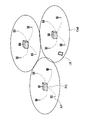
また、将来の無線通信システムにおいては、各基地局装置が地理的に離れた位置に複数のアンテナ装置(例えば、アンテナポート)を具備したRRH(Remote Radio Head)システムの適用が検討されている(図1参照)。RRHシステム(分散アンテナシステムとも呼ぶ)では、図1に示すように、各セルにおいてそれぞれ複数の分散アンテナ(アンテナポート)が分散して設けられている。
例えば、RRHシステムでは、各アンテナポートをそれぞれ一つのアンテナから構成し、各アンテナポートを地理的に離れた位置に配置する。これにより、各セルに在圏するユーザ端末は、複数の送信アンテナポートの中で近接するアンテナポートとデータの送受信を行うことが可能となるため、セル端に位置する場合であっても伝播損失(パスロス)を抑制することが可能となる。
3GPP TS 36.300 "Evolved UTRA and Evolved UTRAN Overall description"
上述したように、RRHシステムを適用する場合、一般に、各セルに在圏するユーザ端末は、それぞれ受信品質(例えば、SINR)が最も高いアンテナポートに接続しようとする。例えば、各ユーザ端末は、分散して配置されたアンテナポートの中で距離が最も近いアンテナポートに接続する。
しかし、複数のセルが隣接して配置されるネットワーク(マルチセルラーネットワーク)構成では、あるアンテナポートから送信された信号が、隣接セルのユーザ端末に対して干渉となるおそれがある。他のユーザ端末(例えば、隣接セルのユーザ端末)への干渉が大きくなると、システム全体としてのスループットが低下するおそれがある。
本発明はかかる点に鑑みてなされたものであり、複数セルを有する環境(マルチセルラー環境)下でRRHシステムを適用する場合に、システム全体のスループットが低下することを抑制することができる基地局、ユーザ端末及び無線通信方法を提供することを目的とする。
本発明の基地局は、各セルにそれぞれ複数のアンテナポートが分散して配置されるRRHシステムにおける基地局であって、各ユーザ端末が接続するアンテナポートを各ユーザ端末が在圏するセルのアンテナポートから選択する選択部と、アンテナポートの送信電力を制御する電力設定部と、を有し、前記選択部及び前記電力設定部は、各ユーザ端末のターゲットSINR(t)とアンテナポートの送信電力について所定条件を設定し、複数セルのユーザ端末のSINRの中で最小となるSINRの値が最大となるように、各ユーザ端末に対するアンテナポートを選択すると共に、各アンテナポートの送信電力を制御することを特徴とする。
本発明によれば、複数セルを有する環境(マルチセルラー環境)下でRRHシステムを適用する場合に、各ユーザ端末のSINRの中で最も低いSINRを最大化することでシステム全体のスループットが低下することを抑制することができる。
まず、本実施の形態において適用可能なRRHシステムについて図2を参照して説明する。なお、図2は、マルチセルラー環境で適用するRRHシステムの一例であり、本実施の形態では、1クラスタ当たりのセル数、各セルのアンテナポート(AP)数等はこれに限られない。
図2は、3つのセル(Cell)が1つのクラスタを形成し、各セルにそれぞれ4個のアンテナポート(分散アンテナ)が設けられた場合を示している。各セルを形成する無線基地局(BS)と当該セルに配置される分散アンテナは光ファイバ等のバックホールリンクを介して接続した構成とすることができる。なお、無線基地局が分散アンテナと同じ周波数を利用するアンテナ(アンテナポート)を備えた構成としてもよい。この場合には、各セルにおけるアンテナポート数が5個となる。
図2に示すRRHシステムは、セルの中央のみに無線基地局を配置して信号の送受信を行うネットワーク構成と異なり、アンテナポートがカバレッジ全体にわたって分散して配置される。このため、ユーザ端末(UE)がセル端に位置する場合であっても、ユーザ端末はいずれかのアンテナポートに近接する位置に配置される。
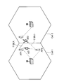
ところで、図2に示すようなRRHシステムでは、通常、各セルのユーザ端末は、受信品質(例えば、SINR)が最も高くなるアンテナポートに接続する。例えば、図3に示す場合、セル1(Cell1)に在圏するユーザ端末1(UE1)は、セル1に配置された複数のアンテナポートの中で最も受信品質が高い(例えば、距離が最も近い)アンテナポート1(AP1)へ接続する。
例えば、受信品質として以下の式(1)を用いて算出されたSINRを用い、当該SINRが最も高くなるアンテナポートに各ユーザ端末が接続するように制御する。
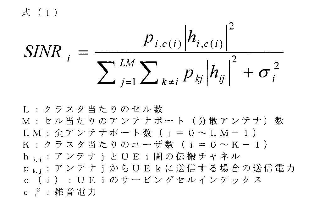
しかし、図3に示すように、ユーザ端末1がSINRの最も高くなるアンテナポート1(AP1)に接続する場合、アンテナポート1からユーザ端末1に対して送信される信号が、セル2(Cell2)に在圏するユーザ端末2に対して大きな干渉となるおそれがある。このように、各ユーザ端末がSINRの最も高いアンテナポートに接続する場合であっても、隣接セルのユーザ端末に対する干渉源となり、結果的にシステム全体のスループットが低下してしまう。
一方で、本発明者等は、図3に示す場合に、ユーザ端末1(UE1)をSINRの最も高いアンテナポート1ではなく、隣接セルのユーザ端末2(UE2)への干渉が小さいアンテナポート2(AP2)に接続させることにより、ユーザ端末1の受信品質は多少低下するがシステム全体のスループットを向上できることを見出した。このように、本発明者等は、マルチセルラーRRHシステムにおいて、各ユーザ端末にとってSINRが最も高くなるアンテナポートを選択することは、クラスタ全体(例えば、隣接セル)を考慮した際に必ずしも最適な選択になるとは限らないことを見出した。
そこで、本発明者等は、マルチセルラー環境のRRHシステムにおいて、各ユーザ端末をSINRの最も高いアンテナポートに接続させるのではなく、複数のユーザ端末のSINRの中で最小となるSINRの値が最大となるように、各ユーザ端末が接続するアンテナポートを選択すると共に、当該アンテナポートの送信電力を制御することを着想した。複数のユーザ端末のSINRの中で最も低いSINRの値が最大となるように(max-mini)、各ユーザ端末に対するアンテナポートの選択及び送信電力の制御を行うことにより、隣接セルも含めた複数のユーザ端末に対して最低限の品質を保証することが可能となる。
具体的には、各ユーザ端末のターゲットSINR、各アンテナポート当たりの送信電力値、各ユーザ端末に対するアンテナポートの送信電力値等についてそれぞれ所定条件を設定する。そして、所定条件を満たすように各ユーザ端末が接続するアンテナポートと当該アンテナポートの送信電力を連帯して(jointly)制御する。つまり、基地局は、線形計画法(linear programming method)を用いて、各ユーザ端末に対するアンテナポートを選択すると共に、当該アンテナポートの送信電力を制御する。なお、アンテナポートの選択及び送信電力制御は、所定周期毎に行ってもよいし、通信環境の変化(スループットの低下)に基づいて行うことも可能である。
以下に、各ユーザ端末が接続するアンテナポートの選択方法と、当該アンテナポートの送信電力方法について説明する。なお、以下の説明では、各セルにそれぞれ複数のユーザ端末が在圏し、各ユーザ端末がそれぞれ1つのアンテナ(single antenna)を具備すると共に、在圏セルの1つのアンテナポートに接続するシナリオを想定する。このシナリオでは、各セルにおけるユーザ端末の同期手順を簡略化することが可能となる。もちろん、本実施の形態が適用可能な構成は必ずしもこれに限られない。
また、各セルに在圏する複数のユーザ端末は、同一のリソースブロックに同時に割当て可能となっている。また、各ユーザデータは、在圏するセルでのみ利用可能であり、異なるセル間でのユーザデータ交換を考慮に入れない場合を想定する。もちろん、本実施の形態はこれに限られない。
<アンテナポート選択方法>
基地局は、クラスタ内の各ユーザ端末がそれぞれ接続するアンテナポートを選択する。なお、本実施の形態における基地局は、クラスタを形成する各セルの無線基地局における情報を集約する基地局であればよい。例えば、各セルの無線基地局の中で代表となる無線基地局、又は各無線基地局と接続された集約局を基地局とすることができる。
基地局は、クラスタ内の各ユーザ端末がそれぞれ接続するアンテナポートを選択する。なお、本実施の形態における基地局は、クラスタを形成する各セルの無線基地局における情報を集約する基地局であればよい。例えば、各セルの無線基地局の中で代表となる無線基地局、又は各無線基地局と接続された集約局を基地局とすることができる。
基地局は、所定条件の下、各セル(例えば、セルm)の送信電力の合計がそれぞれ最小となるように、各ユーザ端末が接続するアンテナポートを選択する。所定条件としては、各ユーザ端末のターゲットSINR(t)、各アンテナポート当たりの送信電力値、各ユーザ端末に対するアンテナポートの送信電力値についてそれぞれ条件を設定する。例えば、各ユーザ端末におけるSINRが所定SINR(ターゲットSINR(t))以上、各アンテナポートのユーザ端末に対する送信電力の合計が所定値(例えば、アンテナポート当たりの最大送信電力P)以下、且つ、各ユーザ端末に対する各アンテナポートの送信電力の合計が所定値(例えば、最大送信電力P)以下、となる条件を設定することができる。
例えば、基地局は、以下の式(2)を利用して、ユーザ端末が接続するアンテナポートを選択する。

上記式(2)において、||pim||は、ユーザ端末iに対するサービングセルmの各アンテナポートの送信電力の総和に相当する。式(2)では、各ユーザ端末におけるSINRがターゲットSINR(t)以上(条件1)、各アンテナポートのユーザ端末に対する送信電力の合計が所定値以下(条件2)、且つ、各ユーザ端末に対する各アンテナポートの送信電力の合計が所定値以下(条件3)を仮定した線形計画法(linear programming method)を利用する。
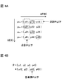
図4Aに、上記式(2)を用いる際に、各ユーザ端末に対するアンテナポート選択の概念図を示す。図4Aでは、横方向にアンテナポート(M)、縦方向にユーザ端末(K)が設定されており、ここでは、アンテナポート数が3、ユーザ端末数が4と想定する場合を示している。
基地局は、各アンテナポートのユーザ端末に対する送信電力の合計が所定値以下(条件2)、且つ、各ユーザ端末に対する各アンテナポートの送信電力の合計が所定値以下(条件3)、となるように各アンテナポートの送信電力を仮定する。そして、ユーザ端末毎に、送信電力が最も高くなる(SINRが最も高くなる)アンテナポートを選択する。図4Aでは、ユーザ端末1~4に対して、それぞれアンテナポート2、1、2、3(ベクトルp12、p21、p32、p43)を選択する場合を示している。
このように、基地局は、上記式(2)を利用して、各セルのユーザ端末に対して在圏するセルの特定のアンテナポートを選択することができる。
<アンテナポート送信電力設定方法>
次に、基地局は、ユーザ端末毎に、選択したアンテナポートの送信電力を制御する。具体的には、選択したベクトルp=[p12、p21、p32、p43]の各要素が所定値(例えば、最大送信電力P)以下となるようにアンテナポートの送信電力を制御する。
次に、基地局は、ユーザ端末毎に、選択したアンテナポートの送信電力を制御する。具体的には、選択したベクトルp=[p12、p21、p32、p43]の各要素が所定値(例えば、最大送信電力P)以下となるようにアンテナポートの送信電力を制御する。
基地局は、例えば、以下の式(3)を利用して、ユーザ端末が接続するアンテナポートの送信電力を制御する(図4B参照)。
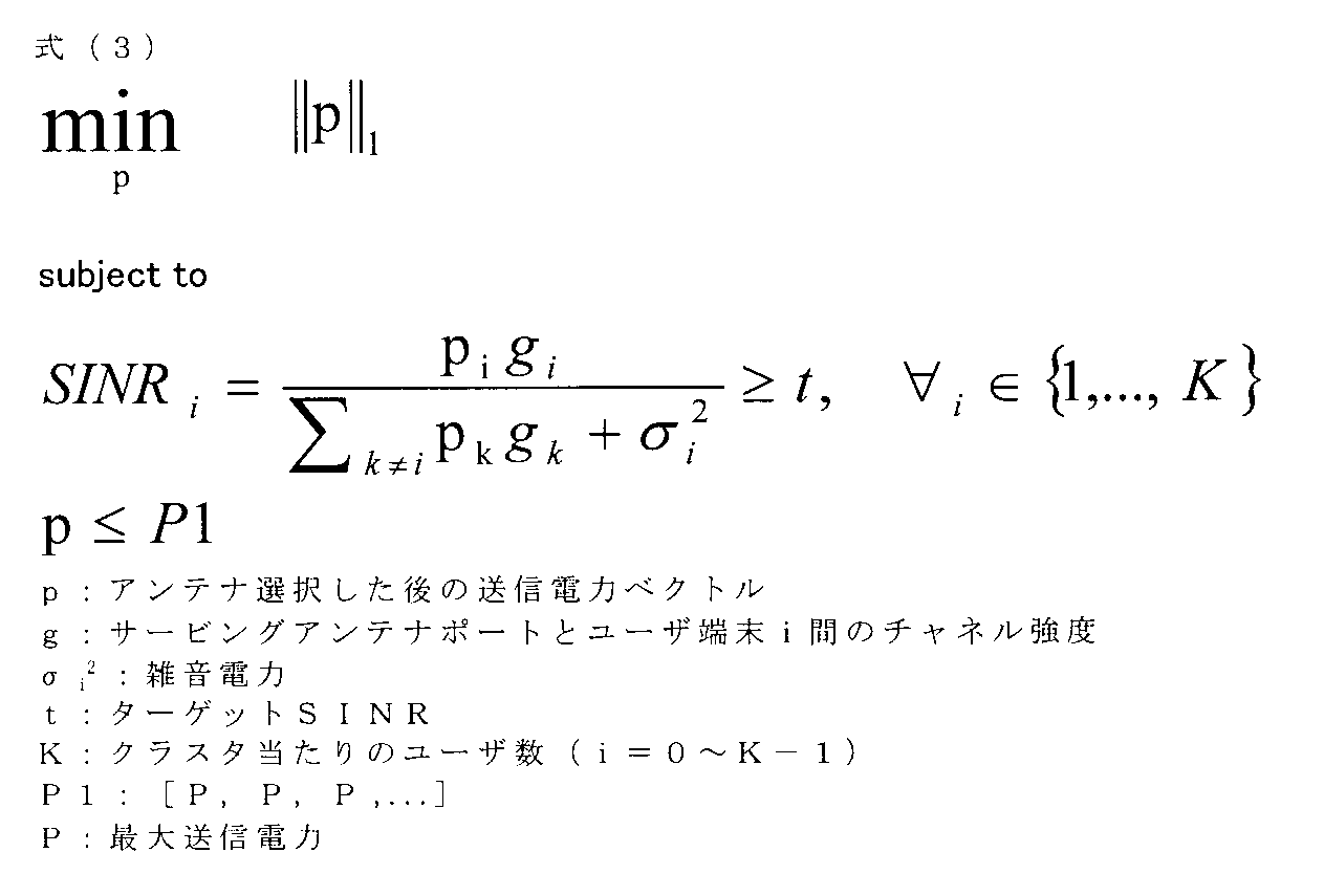
以上のように、本実施の形態では、各ユーザ端末のSINRの中で最小となるSINRが最大となるように、上記式(2)、(3)で規定された条件(線形計画法)を利用して、各ユーザ端末が接続するアンテナポートと当該アンテナポートの送信電力を連帯して(jointly)制御する。これにより、複数セルで構成されるネットワーク環境においてRRHシステムを適用する場合であっても、隣接セルへの干渉を低減し、クラスタ内のユーザ端末に対して最低限の品質を保証すること(max-mini)が可能となる。
なお、本実施の形態において、システムで達成可能なターゲットSINR(t)の最大値を規定するために、二分検索法(bisection search method)を適用することができる。例えば、ターゲットSINR(t)として、まずSINRの最大値(tmax)と最小値(tmin)の平均値(t=(tmin+tmax)/2)を設定する。最小値(tmin)は、例えば0とすることができる。そして、設定したターゲットSINR(t)を用いて上記式(2)、(3)で規定された条件(線形計画法)に基づいて計算を行い、実現可能であるか否か(tが適切であるか否か)判断する。実現可能である場合にはさらに二分法を用いてtの値を増加させ、実現不可能である場合にはtの値を減少させて計算を繰り返して行う。これにより、最適なターゲットSINR(Max SINR)を見つけると共に、ユーザ端末に対するアンテナポートの選択及び当該アンテナポートの送信電力制御を適切に行うことができる。
(無線通信システムの構成)
以下、本実施の形態に係る無線通信システムについて、詳細に説明する。
以下、本実施の形態に係る無線通信システムについて、詳細に説明する。
図5は、本実施の形態に係る無線通信システムの概略構成図である。なお、図5に示す無線通信システムは、例えば、LTEシステム或いは、SUPER 3G等が包含されるシステムである。この無線通信システムでは、LTEシステムのシステム帯域幅を1単位とする複数の基本周波数ブロック(コンポーネントキャリア)を一体としたキャリアアグリゲーション(CA)を適用することができる。また、この無線通信システムは、IMT-Advancedと呼ばれても良いし、4G、FRA(Future Radio Access)と呼ばれても良い。
図5に示す無線通信システム1は、マクロセルC1を形成する無線基地局11と、マクロセルC1内に配置された複数のアンテナポート(分散アンテナ)12a~12cとを備えている。また、無線通信システム1は、上記図1に示したように複数のセルで1クラスタが構成されている(マルチセルラーRRHシステム)。各ユーザ端末20は、在圏するセルに配置されたアンテナポート(例えば、1つのアンテナポート)に接続して、信号の送受信を行う構成とすることができる。
無線基地局11とアンテナポート12間は、有線接続(Optical fiber等)で接続されている。
無線基地局11は、上位局装置30に接続され、上位局装置30を介してコアネットワーク40に接続される。なお、上位局装置30には、例えば、アクセスゲートウェイ装置、無線ネットワークコントローラ(RNC)、モビリティマネジメントエンティティ(MME)等が含まれるが、これに限定されるものではない。また、各アンテナポート12は、無線基地局11を介して上位局装置に接続されており、各アンテナポート12におけるスケジューリング制御は無線基地局11(又は、各無線基地局11を集約する集約局)で行うことができる。
なお、無線基地局11は、eNodeB、マクロ基地局、送受信ポイントなどと呼ばれてもよい。また、アンテナポート12は、局所的なカバレッジを有するアンテナ装置であり、RRH(Remote Radio Head)、分散アンテナ、送受信ポイントなどと呼ばれてもよい。
各セルを形成する無線基地局11は、それぞれ集約局として機能する基地局に接続された構成とすることができる。あるいは、クラスタを形成する各セルの無線基地局の中で、代表となる無線基地局を設けて当該無線基地局に情報を集約する構成としてもよい。また、各ユーザ端末20は、LTE、LTE-A等の各種通信方式に対応した端末であり、移動通信端末だけでなく固定通信端末を含んでよい。
本実施の形態の無線通信システムにおいては、無線アクセス方式として、下りリンクについてはOFDMA(直交周波数分割多元接続)、上りリンクについてはSC-FDMA(シングルキャリア-周波数分割多元接続)を適用することができる。OFDMAは、周波数帯域を複数の狭い周波数帯域(サブキャリア)に分割し、各サブキャリアにデータをマッピングして通信を行うマルチキャリア伝送方式である。SC-FDMAは、システム帯域幅を端末毎に1つ又は連続したリソースブロックからなる帯域に分割し、複数の端末が互いに異なる帯域を用いることで、端末間の干渉を低減するシングルキャリア伝送方式である。なお、本実施の形態は、マルチセルラーRRHシステムを適用するシステムであれば適用することが可能である。
ここで、図5に示す無線通信システムで用いられる通信チャネルの一例について説明する。下りリンクの通信チャネルは、各ユーザ端末20で共有されるPDSCH(Physical Downlink Shared Channel)と、下りL1/L2制御チャネル(PDCCH、PCFICH、PHICH、拡張PDCCH)とを有する。PDSCHにより、ユーザデータ及び上位制御情報が伝送される。PDCCH(Physical Downlink Control Channel)により、PDSCHおよびPUSCHのスケジューリング情報等が伝送される。PCFICH(Physical Control Format Indicator Channel)により、PDCCHに用いるOFDMシンボル数が伝送される。PHICH(Physical Hybrid-ARQ Indicator Channel)により、PUSCHに対するHARQのACK/NACKが伝送される。また、拡張PDCCH(EPDCCH)により、PDSCH及びPUSCHのスケジューリング情報等が伝送されてもよい。このEPDCCHは、PDSCH(下り共有データチャネル)と周波数分割多重される。
上りリンクの通信チャネルは、各ユーザ端末20で共有される上りデータチャネルとしてのPUSCH(Physical Uplink Shared Channel)と、上りリンクの制御チャネルであるPUCCH(Physical Uplink Control Channel)とを有する。このPUSCHにより、ユーザデータや上位制御情報が伝送される。また、PUCCHにより、下りリンクの無線品質情報(CQI:Channel Quality Indicator)、送達確認信号(ACK/NACK)等が伝送される。なお、以下の説明では、無線基地局12がTDDを適用する場合について説明する。
また、下りリンクにおいては、参照信号(例えば、セル固有参照信号(CRS:Cell specific Reference Signal)、ユーザ固有の復調用参照信号(DM-RS)、チャネル状態測定用参照信号(CSI-RS:Channel State Information-Reference Signal)等)が送信され、各ユーザ端末は当該参照信号を利用して受信電力測定や受信処理を行う。また、上りリンクにおいては、移動端末装置(UE:User Equipment)からチャネル品質測定用のSRS(Sounding Reference Signal)が送信され、無線基地局は当該SRSに基づいて上りリンクのチャネル品質を測定することができる。
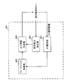
図6は、本実施の形態に係る基地局10(例えば、代表無線基地局11)の全体構成図である。基地局10は、送受信アンテナ101と、アンプ部102と、送受信部103と、ベースバンド信号処理部104と、呼処理部105と、伝送路インターフェース106とを備えている。
下りリンクにより基地局10からユーザ端末20に送信されるユーザデータは、上位局装置30から伝送路インターフェース106を介してベースバンド信号処理部104に入力される。また、各アンテナポート12との情報のやり取りも伝送路インターフェース106を介して行うことができる。
ベースバンド信号処理部104では、PDCPレイヤの処理、ユーザデータの分割・結合、RLC(Radio Link Control)再送制御の送信処理などのRLCレイヤの送信処理、MAC(Medium Access Control)再送制御、例えば、HARQの送信処理、スケジューリング、伝送フォーマット選択、チャネル符号化、逆高速フーリエ変換(IFFT:Inverse Fast Fourier Transform)処理、プリコーディング処理が行われて各送受信部103に転送される。また、下りリンクの制御チャネルの信号に関しても、チャネル符号化や逆高速フーリエ変換等の送信処理が行われて、各送受信部103に転送される。
また、ベースバンド信号処理部104は、上位レイヤシグナリング(例えば、RRCシグナリング、報知情報等)により、ユーザ端末20に対して、当該セルにおける通信のための制御情報を通知する。当該セルにおける通信のための情報には、例えば、上りリンク又は下りリンクにおけるシステム帯域幅等が含まれる。また、各ユーザ端末が接続するアンテナポートに関する情報を、上位レイヤシグナリングによりユーザ端末20に通知することも可能である。
送受信部103は、ベースバンド信号処理部104からプリコーディングして出力されたベースバンド信号を無線周波数帯に変換する。アンプ部102は、周波数変換された無線周波数信号を増幅して送受信アンテナ101により送信する。
一方、上りリンクによりユーザ端末20から基地局10に送信されるデータについては、送受信アンテナ101で受信された無線周波数信号がアンプ部102で増幅され、送受信部103で周波数変換されてベースバンド信号に変換され、ベースバンド信号処理部104に入力される。
ベースバンド信号処理部104では、入力されたベースバンド信号に含まれるユーザデータに対して、FFT処理、IDFT処理、誤り訂正復号、MAC再送制御の受信処理、RLCレイヤ、PDCPレイヤの受信処理がなされ、伝送路インターフェース106を介して上位局装置30に転送される。呼処理部105は、通信チャネルの設定や解放等の呼処理や、基地局10の状態管理や、無線リソースの管理を行う。
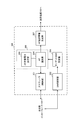
図7は、本実施の形態に係る基地局10が有するベースバンド信号処理部104の主な機能構成図である。なお、図7においては、本実施の形態で特に関連のある機能構成図を主に示しているが、基地局10は、通信に必要な他の機能構成も備えている。
図7に示すように、基地局10が有するベースバンド信号処理部104は、スケジューラ(制御部)301と、SINR取得部302と、アンテナポート(AP)送信電力設定部303及びアンテナポート(AP)選択部304を具備するアンテナポート制御部305と、ターゲットSINR設定部306と、アンテナポート(AP)選択情報生成部307と、を含んで構成されている。
スケジューラ(制御部)301は、PDSCHで送信される下りデータ信号、PDCCH及び/又は拡張PDCCH(EPDCCH)で伝送される下り制御信号、下り参照信号等のスケジューリングを制御する。また、スケジューラ301は、PUSCHで伝送される上りデータ、PUCCH又はPUSCHで伝送される上り制御情報、上り参照信号のスケジューリングの制御(割当て制御)も行う。上りリンク信号(上り制御信号、上りユーザデータ)の割当て制御に関する情報は、下り制御信号(DCI)を用いてユーザ端末に通知される。
具体的に、スケジューラ301は、上位局装置30からの指示情報や各ユーザ端末20からのフィードバック情報(例えば、CQI、RIなどを含むCSI)に基づいて、無線リソースの割り当てを行う。また、スケジューラ301は、複数のアンテナポート12における送受信信号のスケジューリングも行う。
SINR取得部302は、各ユーザ端末(例えば、クラスタ内のユーザ端末)のSINRに関する情報を取得する。例えば、SINR取得部302は、上記式(1)を利用して算出された各ユーザ端末のSINRに関する情報を取得する。ターゲットSINR設定部306は、アンテナポート制御部305で必要となるターゲットSINRを設定する。例えば、ターゲットSINR設定部306は、二分検索法(bisection search method)を適用してターゲットSINR(t)を設定し、アンテナポート制御部305に出力する。なお、ターゲットSINR設定部306の機能をアンテナポート制御部305に設けてもよい。
アンテナポート制御部305は、アンテナポート選択部304及びアンテナポート送信電力設定部303を用いて、複数のユーザ端末のSINRの中で最も低いSINRの値を最大とする(max-mini)ように、各ユーザ端末に対してアンテナポートを選択すると共にアンテナポートの送信電力を制御する。
アンテナポート選択部304は、所定条件の下、各セル(例えば、セルm)の送信電力の合計がそれぞれ最小となるように、各ユーザ端末が接続するアンテナポートを選択する。所定条件としては、各ユーザ端末のターゲットSINR(t)、各アンテナポートのユーザ端末に対する送信電力の合計値、各ユーザ端末に対する各アンテナポートの送信電力の合計値についてそれぞれ条件を設定する。例えば、アンテナポート選択部304は、上述した式(2)を利用して、ユーザ端末が接続するアンテナポートを選択する(上記図4A参照)。
アンテナポート送信電力設定部303は、ユーザ端末毎に、選択したアンテナポートの送信電力を制御する。例えば、アンテナポート送信電力設定部303は、上述した式(3)を利用して、ユーザ端末が接続するアンテナポートの送信電力を制御する(上記図4B参照)。
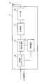
図8にアンテナポート制御部305における動作の一例を示す。なお、図8Aは、ターゲットSINR設定部306とアンテナポート制御部305における動作手順を示すフローチャート図に相当し、図8Bは、適用するアルゴリズムの一例に相当する。なお、図8Bにおける(2)、(3)は、それぞれ上記式(2)、式(3)に相当する。
まず、ターゲットSINR設定部306は、ターゲットSINR(t)として、SINRの最大値(tmax)と最小値(tmin)の平均値(t=(tmin+tmax)/2)を設定する(Step11)。そして、アンテナポート制御部305は、当該ターゲットSINR(t)を用いて上記式(2)、式(3)で規定された条件(線形計画法)に基づいた計算を行い(Step12)、実現可能であるか否か(tが適切であるか否か)判断する(Step13)。アンテナポート制御部305は、実現可能である場合には二分法を用いてtの値を増加させ、実現不可能である場合にはtの値を減少させて計算を繰り返して行う。これにより、最適なターゲットSINR(Max SINR)を見つけることができる。
アンテナポート制御部305は、各ユーザ端末がそれぞれ1つのサービングAP(接続AP)のみ有しているか判断する(Step14)。各ユーザ端末に1つのサービングAPが割当てられている場合には、Step13で設定した各ユーザ端末のAPと各APの送信電力を用いて通信を行う。一方で、各ユーザ端末に1つのサービングAPが割当てられていない場合には、再度最適化処理を行ってユーザ端末毎に最も送信電力が高くなるアンテナポートを選択する(Step15)。
上述の動作で各ユーザ端末に対するアンテナポートを選択したアンテナポート選択部304は、各ユーザ端末に対して選択したアンテナポートに関する情報をスケジューラ301、アンテナポート選択情報生成部307に出力する。
アンテナポート選択情報生成部307は、アンテナポート選択部304から出力された情報に基づいて、各ユーザ端末に対応するAPに関する情報を生成する。なお、アンテナポート選択情報生成部307で生成された情報は、上位レイヤシグナリング(例えば、RRCシグナリング)や下り制御情報に含めて各ユーザ端末に通知することができる。
図9は、本実施の形態に係るユーザ端末20の全体構成図である。ユーザ端末20は、送受信アンテナ201と、アンプ部202と、送受信部(受信部)203と、ベースバンド信号処理部204と、アプリケーション部205とを備えている。
下りリンクのデータについては、送受信アンテナ201で受信された無線周波数信号がそれぞれアンプ部202で増幅され、送受信部203で周波数変換されてベースバンド信号に変換される。このベースバンド信号は、ベースバンド信号処理部204でFFT処理や、誤り訂正復号、再送制御(HARQ-ACK)の受信処理等がなされる。この下りリンクのデータの内、下りリンクのユーザデータは、アプリケーション部205に転送される。アプリケーション部205は、物理レイヤやMACレイヤより上位のレイヤに関する処理等を行う。また、下りリンクのデータの内、報知情報もアプリケーション部205に転送される。
一方、上りリンクのユーザデータについては、アプリケーション部205からベースバンド信号処理部204に入力される。ベースバンド信号処理部204では、再送制御(HARQ-ACK)の送信処理や、チャネル符号化、プリコーディング、DFT処理、IFFT処理等が行われて送受信部203に転送される。送受信部203は、ベースバンド信号処理部204から出力されたベースバンド信号を無線周波数帯に変換する。その後、アンプ部202は、周波数変換された無線周波数信号を増幅して送受信アンテナ201により送信する。
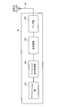
図10は、ユーザ端末20が有するベースバンド信号処理部204の主な機能構成図である。図10に示すように、ユーザ端末20が有するベースバンド信号処理部204は、アンテナポート(AP)選択部401と、受信電力測定部402と、フィードバック制御部403と、上り情報生成部404と、を少なくとも有している。なお、上述したように、ベースバンド信号処理部204は、チャネル符号化、プリコーディング、DFT処理、IFFT処理等を行う機能部も有している。
アンテナポート選択部401は、無線基地局11から通知されるアンテナポート選択情報に基づいて、在圏するセルに配置された複数のアンテナポートの中から接続用のアンテナポート(例えば、1つのAP)を選択する。
受信電力測定部402は、各アンテナポートから送信される下りリンク信号(例えば、参照信号)の受信電力(RSRP、RSRQ等)を測定する。受信電力測定部402は、測定した受信電力に関する情報を上り制御情報生成部404を介して無線基地局へフィードバックすることができる。あるいは、ユーザ端末側で、受信電力に基づいてSINRを算出して当該SINRに関する情報をフィードバックしてもよい。
フィードバック制御部403は、アンテナポート選択部401から出力される情報に基づいて、フィードバック先のアンテナポートを特定すると共に、送達確認信号(ACK/NACK)の生成、PUCCHリソースへの割当て、フィードバックタイミング等を制御する。上り情報生成部404は、フィードバック制御部403からの指示に基づいて、上りリンク信号を生成する。上り制御情報生成部404で生成された上りリンク信号は、送受信部203を介してアンテナポート選択部401で選択されたアンテナポートに対して送信される。
このように、基地局が、複数のユーザ端末のSINRの中で最小となるSINRの値が最大となるように、各ユーザ端末が接続するAPを選択し、当該ユーザ端末が通知されたAPに関する情報に基づいて、特定のAPと送受信を行うことにより、システム全体のスループットが低下することを抑制することができる。
以上、上述の実施形態を用いて本発明について詳細に説明したが、当業者にとっては、本発明が本明細書中に説明した実施形態に限定されるものではないということは明らかである。本発明は、特許請求の範囲の記載により定まる本発明の趣旨及び範囲を逸脱することなく修正及び変更態様として実施することができる。従って、本明細書の記載は、例示説明を目的とするものであり、本発明に対して何ら制限的な意味を有するものではない。
本出願は、2013年7月29日出願の特願2013-156567に基づく。この内容は、全てここに含めておく。
Claims (9)
- 各セルにそれぞれ複数のアンテナポートが分散して配置されるRRHシステムにおける基地局であって、
各ユーザ端末が接続するアンテナポートを各ユーザ端末が在圏するセルのアンテナポートから選択する選択部と、アンテナポートの送信電力を制御する電力設定部と、を有し、
前記選択部及び前記電力設定部は、各ユーザ端末のターゲットSINR(t)とアンテナポートの送信電力について所定条件を設定し、複数セルのユーザ端末のSINRの中で最小となるSINRの値が最大となるように、各ユーザ端末に対するアンテナポートを選択すると共に、各アンテナポートの送信電力を制御することを特徴とする基地局。 - 前記選択部は、各ユーザ端末のターゲットSINR(t)、各アンテナポートのユーザ端末に対する送信電力の合計値、各ユーザ端末に対する各アンテナポートの送信電力の合計値についてそれぞれ所定条件を設定して、各セルの送信電力の合計がそれぞれ最小となるように、各ユーザ端末に対するアンテナポートを選択することを特徴とする請求項1に記載の基地局。
- 前記選択部は、以下の式(2)を利用して各ユーザ端末が接続するアンテナポートを選択することを特徴とする請求項2に記載の基地局。

- 前記電力設定部は、ユーザ端末毎に選択されたアンテナポートの送信電力が所定値以下となるように各アンテナポートの送信電力を制御することを特徴とする請求項1に記載の基地局。
- 前記電力設定部は、以下の式(3)を利用してアンテナポートの送信電力を制御することを特徴とする請求項4に記載の基地局。

- 各ユーザ端末は1つのアンテナを具備し、前記選択部は、各ユーザ端末に対して1つのアンテナポートを割当てることを特徴とする請求項1に記載の基地局。
- 複数のセルで1つのクラスタが構成され、異なるセル間でユーザデータの交換を行わないことを特徴とする請求項1に記載の基地局。
- 各セルにそれぞれ複数のアンテナポートが分散して配置されるRRHシステムにおけるユーザ端末であって、
在圏するセルの無線基地局から通知されるアンテナポート選択情報に基づいて、在圏するセルに配置された複数のアンテナポートの中から接続用のアンテナポートを1つ選択する選択部と、選択したアンテナポートと信号の送受信を行う送受信部と、を有し、
前記接続用のアンテナポートは、複数セルに在圏する複数のユーザ端末のSINRの中で最小となるSINRの値が最大となるように選択されたアンテナポートであることを特徴とするユーザ端末。 - 各セルにそれぞれ複数のアンテナポートが分散して配置されるRRHシステムにおける無線通信方法であって、
各ユーザ端末が接続するアンテナポートを各ユーザ端末が在圏するセルのアンテナポートから選択すると共に、アンテナポートの送信電力を制御する工程を有し、
各ユーザ端末のターゲットSINR(t)とアンテナポートの送信電力について所定条件を設定して、複数のセルのユーザ端末のSINRの中で最小となるSINRの値が最大となるように、各ユーザ端末に対するアンテナポートを選択すると共に、各アンテナポートの送信電力を制御することを特徴とする無線通信方法。
Priority Applications (2)
| Application Number | Priority Date | Filing Date | Title |
|---|---|---|---|
| SG11201601502RA SG11201601502RA (en) | 2013-07-29 | 2014-07-29 | Base station, user terminals and wireless communication method |
| US14/908,905 US9854538B2 (en) | 2013-07-29 | 2014-07-29 | Base station, user terminals and wireless communication method |
Applications Claiming Priority (2)
| Application Number | Priority Date | Filing Date | Title |
|---|---|---|---|
| JP2013156567A JP6234726B2 (ja) | 2013-07-29 | 2013-07-29 | 基地局、ユーザ端末及び無線通信方法 |
| JP2013-156567 | 2013-07-29 |
Publications (1)
| Publication Number | Publication Date |
|---|---|
| WO2015016226A1 true WO2015016226A1 (ja) | 2015-02-05 |
Family
ID=52431757
Family Applications (1)
| Application Number | Title | Priority Date | Filing Date |
|---|---|---|---|
| PCT/JP2014/069962 Ceased WO2015016226A1 (ja) | 2013-07-29 | 2014-07-29 | 基地局、ユーザ端末及び無線通信方法 |
Country Status (4)
| Country | Link |
|---|---|
| US (1) | US9854538B2 (ja) |
| JP (1) | JP6234726B2 (ja) |
| SG (1) | SG11201601502RA (ja) |
| WO (1) | WO2015016226A1 (ja) |
Families Citing this family (5)
| Publication number | Priority date | Publication date | Assignee | Title |
|---|---|---|---|---|
| JP6400614B2 (ja) * | 2016-02-12 | 2018-10-03 | 日本電信電話株式会社 | 分散アンテナを用いた無線基地局およびアンテナ切替方法 |
| KR102439792B1 (ko) | 2018-02-14 | 2022-09-02 | 삼성전자주식회사 | 무선 통신 시스템에서 송신 전력을 결정하기 위한 장치 및 방법 |
| CN109962719B (zh) * | 2019-01-28 | 2021-08-06 | Oppo广东移动通信有限公司 | 天线控制方法和系统、电子设备、计算机可读存储介质 |
| CN110493831B (zh) * | 2019-07-30 | 2021-09-28 | 维沃移动通信有限公司 | 一种功率确定方法及终端设备 |
| WO2022240683A1 (en) * | 2021-05-10 | 2022-11-17 | Kyocera Corporation | Randomization of multiple discovery resource types |
Citations (4)
| Publication number | Priority date | Publication date | Assignee | Title |
|---|---|---|---|---|
| JP2002252619A (ja) * | 2001-02-26 | 2002-09-06 | Yrp Mobile Telecommunications Key Tech Res Lab Co Ltd | パケット通信装置 |
| JP2009246974A (ja) * | 2008-03-31 | 2009-10-22 | Mitsubishi Electric Research Laboratories Inc | 分散アンテナシステムおよびその容量を最大にするための方法 |
| WO2012033887A1 (en) * | 2010-09-08 | 2012-03-15 | Telcordia Technologies, Inc. | A distributed power level selection method and system for cellular wireless networks under joint constraints |
| JP2013118619A (ja) * | 2011-11-01 | 2013-06-13 | Sharp Corp | 移動局装置、通信システム、通信方法および集積回路 |
Family Cites Families (4)
| Publication number | Priority date | Publication date | Assignee | Title |
|---|---|---|---|---|
| KR101084142B1 (ko) * | 2005-08-25 | 2011-11-17 | 엘지전자 주식회사 | 하향공유채널의 데이터 송수신 방법 |
| US8213533B2 (en) * | 2008-02-11 | 2012-07-03 | Telefonaktiebolaget Lm Ericsson (Publ) | Distributed antenna diversity transmission method |
| US8369791B2 (en) * | 2009-09-22 | 2013-02-05 | Telefonaktiebolaget L M Ericsson (Publ) | Multi-user beamforming with inter-cell interference suppression |
| JP5270648B2 (ja) * | 2010-12-08 | 2013-08-21 | 株式会社日立製作所 | 分散アンテナシステム、基地局装置、アンテナ選択制御方法 |
-
2013
- 2013-07-29 JP JP2013156567A patent/JP6234726B2/ja active Active
-
2014
- 2014-07-29 US US14/908,905 patent/US9854538B2/en not_active Expired - Fee Related
- 2014-07-29 WO PCT/JP2014/069962 patent/WO2015016226A1/ja not_active Ceased
- 2014-07-29 SG SG11201601502RA patent/SG11201601502RA/en unknown
Patent Citations (4)
| Publication number | Priority date | Publication date | Assignee | Title |
|---|---|---|---|---|
| JP2002252619A (ja) * | 2001-02-26 | 2002-09-06 | Yrp Mobile Telecommunications Key Tech Res Lab Co Ltd | パケット通信装置 |
| JP2009246974A (ja) * | 2008-03-31 | 2009-10-22 | Mitsubishi Electric Research Laboratories Inc | 分散アンテナシステムおよびその容量を最大にするための方法 |
| WO2012033887A1 (en) * | 2010-09-08 | 2012-03-15 | Telcordia Technologies, Inc. | A distributed power level selection method and system for cellular wireless networks under joint constraints |
| JP2013118619A (ja) * | 2011-11-01 | 2013-06-13 | Sharp Corp | 移動局装置、通信システム、通信方法および集積回路 |
Non-Patent Citations (1)
| Title |
|---|
| HUAWEI ET AL.: "Discussion on Side Condition and Maximum Size of CRM for CoMP", 3GPP TSG-RAN WG4#64 R4-124099, Retrieved from the Internet <URL:http://www.3gpp.org/ftp/tsg_ran/WG4_Radio/TSGR4_64/Docs/R4-124099.zip> [retrieved on 20120806] * |
Also Published As
| Publication number | Publication date |
|---|---|
| JP6234726B2 (ja) | 2017-11-22 |
| SG11201601502RA (en) | 2016-04-28 |
| US9854538B2 (en) | 2017-12-26 |
| US20160278023A1 (en) | 2016-09-22 |
| JP2015027027A (ja) | 2015-02-05 |
Similar Documents
| Publication | Publication Date | Title |
|---|---|---|
| US10389512B2 (en) | User terminal, base station and radio communication method | |
| CN108141428B (zh) | 无线基站、用户终端以及无线通信方法 | |
| US10064102B2 (en) | User terminal, radio base station and radio communication method | |
| EP3179821B1 (en) | User terminal, wireless communication system, and wireless communication method | |
| JP5781016B2 (ja) | 無線基地局、無線通信システム及び無線通信方法 | |
| JPWO2016199768A1 (ja) | ユーザ端末、無線基地局及び無線通信方法 | |
| WO2016159230A1 (ja) | ユーザ端末、無線基地局及び無線通信方法 | |
| EP3099131A1 (en) | User terminal, wireless base station, and wireless communication method | |
| JPWO2016013446A1 (ja) | 無線基地局および無線通信方法 | |
| WO2017130992A1 (ja) | ユーザ端末、無線基地局及び無線通信方法 | |
| US20180323949A1 (en) | Radio base station, user terminal and radio communication method | |
| JP5911320B2 (ja) | 無線通信システム、ユーザ端末、無線基地局装置及び無線通信方法 | |
| JP6234726B2 (ja) | 基地局、ユーザ端末及び無線通信方法 | |
| WO2013069759A1 (ja) | 無線通信システム、無線通信方法、無線基地局装置及びユーザ端末 | |
| US9444527B2 (en) | Radio communication system, radio base station apparatus, user terminal and radio communication method | |
| US20190014588A1 (en) | User terminal, radio base station, and radio communication method | |
| WO2014181626A1 (ja) | ユーザ端末、無線基地局および無線通信方法 | |
| WO2015045960A1 (ja) | ユーザ端末および無線通信方法 | |
| US10609652B2 (en) | User terminal, radio base station and radio communication method | |
| JP6254240B2 (ja) | ユーザ端末、無線基地局及び無線通信方法 | |
| EP2765820A1 (en) | Wireless communications system, wireless base station device, user terminal, and wireless communications method | |
| JPWO2016190215A1 (ja) | ユーザ端末、無線基地局及び無線通信方法 | |
| EP3177091A1 (en) | Wireless base station, user terminal, and wireless communication method |
Legal Events
| Date | Code | Title | Description |
|---|---|---|---|
| 121 | Ep: the epo has been informed by wipo that ep was designated in this application |
Ref document number: 14831363 Country of ref document: EP Kind code of ref document: A1 |
|
| NENP | Non-entry into the national phase |
Ref country code: DE |
|
| WWE | Wipo information: entry into national phase |
Ref document number: 14908905 Country of ref document: US |
|
| 122 | Ep: pct application non-entry in european phase |
Ref document number: 14831363 Country of ref document: EP Kind code of ref document: A1 |