WO2015015869A1 - Dispositif de traitement d'image, procédé de traitement d'image, et programme - Google Patents
Dispositif de traitement d'image, procédé de traitement d'image, et programme Download PDFInfo
- Publication number
- WO2015015869A1 WO2015015869A1 PCT/JP2014/063283 JP2014063283W WO2015015869A1 WO 2015015869 A1 WO2015015869 A1 WO 2015015869A1 JP 2014063283 W JP2014063283 W JP 2014063283W WO 2015015869 A1 WO2015015869 A1 WO 2015015869A1
- Authority
- WO
- WIPO (PCT)
- Prior art keywords
- image
- area
- feature
- feature area
- deformation
- Prior art date
Links
Images


Classifications
-
- G—PHYSICS
- G06—COMPUTING; CALCULATING OR COUNTING
- G06V—IMAGE OR VIDEO RECOGNITION OR UNDERSTANDING
- G06V20/00—Scenes; Scene-specific elements
- G06V20/40—Scenes; Scene-specific elements in video content
-
- G—PHYSICS
- G06—COMPUTING; CALCULATING OR COUNTING
- G06T—IMAGE DATA PROCESSING OR GENERATION, IN GENERAL
- G06T7/00—Image analysis
- G06T7/20—Analysis of motion
- G06T7/246—Analysis of motion using feature-based methods, e.g. the tracking of corners or segments
-
- G—PHYSICS
- G06—COMPUTING; CALCULATING OR COUNTING
- G06T—IMAGE DATA PROCESSING OR GENERATION, IN GENERAL
- G06T7/00—Image analysis
- G06T7/0002—Inspection of images, e.g. flaw detection
- G06T7/0012—Biomedical image inspection
- G06T7/0014—Biomedical image inspection using an image reference approach
- G06T7/0016—Biomedical image inspection using an image reference approach involving temporal comparison
-
- G—PHYSICS
- G06—COMPUTING; CALCULATING OR COUNTING
- G06T—IMAGE DATA PROCESSING OR GENERATION, IN GENERAL
- G06T7/00—Image analysis
- G06T7/30—Determination of transform parameters for the alignment of images, i.e. image registration
- G06T7/33—Determination of transform parameters for the alignment of images, i.e. image registration using feature-based methods
-
- G—PHYSICS
- G06—COMPUTING; CALCULATING OR COUNTING
- G06V—IMAGE OR VIDEO RECOGNITION OR UNDERSTANDING
- G06V20/00—Scenes; Scene-specific elements
- G06V20/40—Scenes; Scene-specific elements in video content
- G06V20/41—Higher-level, semantic clustering, classification or understanding of video scenes, e.g. detection, labelling or Markovian modelling of sport events or news items
-
- A—HUMAN NECESSITIES
- A61—MEDICAL OR VETERINARY SCIENCE; HYGIENE
- A61B—DIAGNOSIS; SURGERY; IDENTIFICATION
- A61B1/00—Instruments for performing medical examinations of the interior of cavities or tubes of the body by visual or photographical inspection, e.g. endoscopes; Illuminating arrangements therefor
- A61B1/04—Instruments for performing medical examinations of the interior of cavities or tubes of the body by visual or photographical inspection, e.g. endoscopes; Illuminating arrangements therefor combined with photographic or television appliances
- A61B1/041—Capsule endoscopes for imaging
-
- G—PHYSICS
- G06—COMPUTING; CALCULATING OR COUNTING
- G06T—IMAGE DATA PROCESSING OR GENERATION, IN GENERAL
- G06T2207/00—Indexing scheme for image analysis or image enhancement
- G06T2207/10—Image acquisition modality
- G06T2207/10016—Video; Image sequence
-
- G—PHYSICS
- G06—COMPUTING; CALCULATING OR COUNTING
- G06T—IMAGE DATA PROCESSING OR GENERATION, IN GENERAL
- G06T2207/00—Indexing scheme for image analysis or image enhancement
- G06T2207/10—Image acquisition modality
- G06T2207/10068—Endoscopic image
-
- G—PHYSICS
- G06—COMPUTING; CALCULATING OR COUNTING
- G06T—IMAGE DATA PROCESSING OR GENERATION, IN GENERAL
- G06T2207/00—Indexing scheme for image analysis or image enhancement
- G06T2207/30—Subject of image; Context of image processing
- G06T2207/30004—Biomedical image processing
- G06T2207/30028—Colon; Small intestine
-
- G—PHYSICS
- G06—COMPUTING; CALCULATING OR COUNTING
- G06T—IMAGE DATA PROCESSING OR GENERATION, IN GENERAL
- G06T2207/00—Indexing scheme for image analysis or image enhancement
- G06T2207/30—Subject of image; Context of image processing
- G06T2207/30004—Biomedical image processing
- G06T2207/30096—Tumor; Lesion
-
- G—PHYSICS
- G06—COMPUTING; CALCULATING OR COUNTING
- G06V—IMAGE OR VIDEO RECOGNITION OR UNDERSTANDING
- G06V2201/00—Indexing scheme relating to image or video recognition or understanding
- G06V2201/03—Recognition of patterns in medical or anatomical images
- G06V2201/031—Recognition of patterns in medical or anatomical images of internal organs
-
- G—PHYSICS
- G06—COMPUTING; CALCULATING OR COUNTING
- G06V—IMAGE OR VIDEO RECOGNITION OR UNDERSTANDING
- G06V2201/00—Indexing scheme relating to image or video recognition or understanding
- G06V2201/03—Recognition of patterns in medical or anatomical images
- G06V2201/032—Recognition of patterns in medical or anatomical images of protuberances, polyps nodules, etc.
Definitions
- the present invention relates to an image processing apparatus, an image processing method, a program, and the like.
- Patent Document 1 an object detection means for detecting an object from input image information and a distance and a position of the object with respect to the imaging means when the object is detected by the object detection means.
- a tracking device having a determination means for determining if it is identical.
- JP 2008-217714 A JP, 2009-268005, A JP 2007-257287 A JP, 2010-113616, A
- the movement range of the object made into object is estimated, and the determination of identity is performed based on whether the object of the same characteristic was imaged in the estimated movement range. Further, in Patent Document 2, during a period in which the target object is not detected, the object position is estimated by linear approximation from the history of the object region in the detected period, and the identity is determined based on the estimation result.
- Patent Document 1 and Patent Document 2 it is assumed that an object which is both an object and an object imaged as a background of the object are rigid and move independently.
- the subject performs non-rigid (elastic) motion.
- the subject in the case of a digestive tract image obtained by imaging the inside of the intestine, the subject largely changes the shape due to the peristaltic movement of the intestine. Therefore, even if the methods of Patent Document 1 and Patent Document 2 assuming that the movement of the object is linear are applied to the image sequence for the in-vivo image, the identity of the object is determined with sufficient accuracy. Can not do it.
- deletion of an image that should not be deleted may cause loss of information, or not deleting an image that can be deleted may reduce the effect of saving power of the user (doctor). is there.
- image summary processing with high accuracy is performed by performing processing for determining the identity of feature regions using deformation information obtained based on regions other than at least the feature regions in an image.
- An image processing apparatus, an image processing method, and a program to be realized can be provided.
- One embodiment of the present invention is an image sequence acquiring unit for acquiring an image sequence having consecutive first to N-th (N is an integer of 2 or more (including its value)) images;
- a deformation information calculation unit for obtaining deformation information representing a deformation between images, a feature area detection unit for detecting a feature area in each of the first to Nth images, and the feature area in the i-th image Of the i-th feature area which is the result of the detection process of (1), the (i + 1) -th feature area which is the result of the detection process of the feature area in the (i + 1) -th image, the i-th image and the (i + 1) -th image
- An identity determination unit for performing an identity determination process on the i-th feature area and the (i + 1) -th feature area based on h (i, i + 1) which is the deformation information between them;
- Image summary for the image sequence based on the result of
- deformation information is obtained based on a deformation estimation target area including an area other than the feature area, and the process of determining the identity of the characteristic area is performed using the obtained deformation information.
- it is an area obtained by projecting the ith characteristic area onto the ith + 1 image based on the ith characteristic area and h (i, i + 1). Further includes a deformation estimation processing unit for performing deformation estimation processing for determining a deformation region of the image, and the identity determination unit is based on the i-th deformation region obtained by the deformation estimation processing and the (i + 1) th feature region The identity determination process may be performed between the ith feature area and the (i + 1) th feature area.
- the image sequence acquisition unit acquires a time-series in-vivo image as the image sequence
- the feature region detection unit determines a lesion region and an abnormal mucosa region in the in-vivo image. At least one of the two regions may be detected as the feature region.
- the deformation information calculation unit is configured to: at least the i-th deformation estimation target region including at least a normal mucous membrane region in the i-th image;
- the deformation information may be obtained based on the (i + 1) th deformation estimation target area including the area.
- the identity determining unit when the identity determining unit does not determine that the same feature area is imaged, the identity determining unit determines the predetermined number of images by the predetermined number. The process based on the deformation information may be continued, and the identity determination process may be performed when the feature area is detected in the set number of images or less.
- the feature region is not detected in the (i + 1) -th image, so that the i-th feature region and the (i + 1) -th feature region are the same in the identity determination unit.
- the identity determination unit determines the i-th feature region, and the (i + 2) -th feature region that is the result of the detection process of the feature region in the (i + 2) -th image;
- the identity determination processing of the i-th feature area and the (i + 2) -th feature area is performed based on h (i, i + 2) which is the deformation information between the i-th image and the (i + 2) -th image May be
- the identity determination unit determines the i-th + k-th feature that is the result of the detection process of the i-th feature area and the i-th k + (k is an integer) image of the feature area.
- the identity determination process on the i-th feature region is ended, and In the case where it is not determined that the i characteristic region and the (i + k) characteristic region are identical, if k ⁇ Th, the ith characteristic region and the i th k th image in the (i + k + 1) image
- the i-th is based on the (i + k + 1) -th feature area which is the result of the detection process of the feature area, and h (i, i + k + 1) which is the deformation information between the i-th image and the i + k + 1 image.
- a feature area and the (i + k + 1) th feature It may perform the same determination process in said area.
- the deformation information calculation unit determines an inter-image motion vector at at least one position in an image as the deformation information
- the identity determination unit determines the i-th feature region. And the same one of the i-th feature region and the (i + 1) -th feature region based on the (i + 1) -th feature region and the inter-image motion vector between the i-th image and the (i + 1) -th image.
- a sex determination process may be performed.
- the identity determination unit is a region obtained by projecting the i-th feature region onto the i + 1 th image using h (i, i + 1).
- the identity determination process may be performed based on at least one of shape information, color information, texture information, and position information in an image of the (i + 1) th characteristic region.
- the identity determination unit determines the identity between the ith feature area and the (i + 1) th feature area based on the reliability of h (i, i + 1). You may process.
- the summary processing unit determines that the same feature area is photographed among the first to N-th images. And at least one representative image selected from the same feature area image group set in the image group setting section, and an image group setting section configured to set the same feature area image group composed of different images. And a summary image sequence generation unit for generating an image sequence.
- the summary processing unit may include: area information of the feature area, color information of the feature area, texture information of the feature area, in each image included in the same feature area image group.
- the representative image may be selected based on at least one of position information in an image of a feature area and reliability information of the detection process of the feature area.
- another aspect of the present invention performs processing for acquiring an image sequence having consecutive first to N-th (N is an integer of 2 or more (including its value)) images; Perform deformation information calculation processing for obtaining deformation information representing deformation between two images, perform detection processing of a characteristic region in each of the first to Nth images, and detect the characteristic region in the i-th image
- the identity determination process is performed on the i-th feature area and the (i + 1) -th feature area based on h (i, i + 1) that is deformation information, and the image is determined based on the result of the identity determination process.
- an i-th modification estimation target region including a region other than at least the i-th feature region in the i-th image, and a region other than at least the i + 1-th feature region in the i + 1 th image
- the image processing method for obtaining h (i, i + 1) based on the (i + 1) th deformation estimation target area including.
- Another aspect of the present invention relates to a program that causes a computer to function as the above-described units.
- FIG. 1 is a system configuration example of an image processing apparatus according to the present embodiment.
- FIG. 2 is a detailed system configuration example of the image processing apparatus according to the present embodiment.
- FIGS. 3A to 3C illustrate a method for obtaining deformation information using an area other than the feature area.
- FIG. 4 is an explanatory diagram of a method of the first embodiment.
- FIG. 5 is another explanatory view of the method of the first embodiment.
- FIG. 6 is a flowchart illustrating processing of the first embodiment.
- FIG. 7 is another flowchart illustrating the process of the first embodiment.
- FIG. 8 is an explanatory diagram of a method of the second embodiment.
- FIG. 9 is a flowchart for explaining the process of the second embodiment.
- an image sequence imaged using a capsule endoscope can be considered.
- the capsule endoscope is a capsule-shaped endoscope incorporating a small camera, and captures an image at a given time interval (for example, once every 0.5 seconds). Since a capsule endoscope requires several hours (in some cases, several tens of hours) from internal use to discharge, tens of thousands of captured images are acquired in one examination of one user. In addition, the capsule endoscope stays in the same place or returns in the opposite direction due to the influence of the movement of the living body, and the like during movement in the living body. Therefore, a large number of images capture an object similar to other images, and there are many images that are not useful for diagnosis and the like.
- image summary processing is performed in which a lesion area is detected from the image, an image in which the lesion area is detected is left in the summary image sequence after summary processing, and an image in which the lesion area is not detected is deleted.
- a lesion area may be detected in most of the acquired image sequences. In such a case, even if image summary processing is performed depending on whether or not a lesion area is detected, most images can not be deleted, so the reduction effect of the number of images is low and the burden on the user (doctor) It does not lead to mitigation.
- the present applicant performs processing to determine the identity of a feature area in a given image (in a narrow sense, a lesion area or an abnormal mucous membrane area) and a feature area in another image, based on the result of the process.
- Patent Document 1 and Patent Document 2 There are various known methods for determining the identity of an object captured in an image, as in Patent Document 1 and Patent Document 2.
- the conventional method is not necessarily effective.
- the conventional identity determination method tilting method
- an object to be detected undergoes rigid body deformation.
- Patent Document 1 and Patent Document 2 is a method regarding tracking of a person in a surveillance camera or the like.
- the assumption that deformation takes place, and also that changes in position and size are linear, holds true well.
- such deformation is expressed as "rigid body" deformation. Therefore, there is no particular problem in the estimation of the movement range of Patent Document 1 or the tracking by linear approximation from the history of Patent Document 2.
- the feature area is a lesion area or the like, and the lesion area is generated on the surface of the living body (for example, the mucous membrane of the digestive tract) or stuck to the surface of the living body.
- the living body itself may be soft and elastic, it may change its shape by performing some kind of movement like the intestinal peristalsis. That is, since the characteristic region is not rigidly deformed but non-rigidly (elastically) deformed, it is difficult to make a highly accurate judgment by the conventional identity judgment method.
- the present applicant proposes a method of determining the identity of feature regions based on deformation information between images. Then, when obtaining deformation information, at least an area other than the feature area is used.
- the conventional method when determining the identity between the first feature area in the first image and the second feature area in the second image, they are directly compared. This corresponds to, for example, the case of directly comparing the feature area FA1-1 of the image Y1 in FIG. 4 with the feature area FA1-2 of the image Y2. Therefore, when the subject elastically deforms or the like, the shapes of the first feature area and the second feature area may be largely different, and the accuracy is lowered.
- the deformation information also includes elastic deformation of the subject, so that it is possible to determine the identity with high accuracy even when an in-vivo image or the like is targeted.
- the deformation area is obtained by estimating deformation of the first feature area, and the deformation area is compared with the second feature area. Good.
- the deformation between the first image and the second image is canceled (reduced in a broad sense) by the deformation estimation process using deformation information, so the first feature region and the second feature region Is the same, the difference between the deformation area and the second feature area becomes small, and identity determination can be performed with high accuracy.
- the above method presupposes that deformation information between images is obtained with high accuracy, and if the accuracy of the deformation information is low, the accuracy of the deformation area to be obtained and the identity determination processing using the deformation area The accuracy also decreases.
- the deformation information in the in-vivo image is obtained only from the feature region (lesion region) portion, it is difficult to ensure the accuracy of the deformation information. This is because, in an in-vivo image, the feature region may be shielded by the contents, the eyebrow structure, and the like.
- bubbles or residues in the digestive tract may be imaged, and if the content is at a position covering the lesion area or between the lesion area and the imaging unit, Without the contents, part or all of the lesion area that could have been imaged would be shielded.
- a convex structure such as a weir may be observed in the living body, and the weir may change its position due to the above-mentioned peristaltic movement and the like. Therefore, even if the relevant lesion area can be imaged when only the relative position between the imaging unit and the lesion area is considered, the relevant lesion area is imaged or shielded and can not be imaged depending on the movement of the eyelid or the like.
- the frame rate of imaging is often low. This is particularly noticeable in the case of a capsule endoscope in which the size of a battery or a device is very limited, and for example, as described above, the frame rate may be as low as 2 fps. This low frame rate also causes the accuracy of the deformation information to decrease.
- the applicant at least uses information of an area other than the feature area in the image when obtaining deformation information.
- the feature area and the other area perform the same movement.
- a lesion area which is a characteristic area is stuck to a mucous membrane area which is a background, and a lesion area and a mucous membrane area move (deform) as one.
- the information such as the mucous membrane area is used. It becomes possible to obtain deformation information with high accuracy.
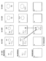
- FIG. 3 (A) to FIG. 3 (C) Specific examples are shown in FIG. 3 (A) to FIG. 3 (C).
- FIG. 3A when the feature area FA1 is detected in the first image, the area corresponding to FA1 in the second image is supposed to be originally imaged in the area of FA2.
- the shielded area MA including FA2 has been shielded by the contents.
- the corresponding area can not be found, and appropriate deformation information can not be obtained.
- FIG. 3C can not be derived from an image targeted by a conventional method such as Patent Document 1 or Patent Document 2.
- Patent Document 1 an object (such as a person) to be detected and a background (such as a landscape) move (deform) independently.
- the object 1 captured in R3 in the first image moves out of the imaging range until the second image is captured.
- an object 2 different from the object 1 may enter the area R4 before the second image is captured.
- the determination that R3 and R4 correspond to each other is not appropriate, and the information of the area other than the feature area is not effective in deriving the deformation information for obtaining the deformation area.
- 3C corresponds to a state in which a motion vector is estimated for each point included in R3 by interpolation processing (correction processing) using a motion vector in R1 with high reliability. That is, by the method according to the present embodiment, it is accurately determined to which point (region) in the second image the arbitrary point (arbitrary region) of the first image is moved (deformed). It is possible.
- the image processing apparatus acquires an image sequence that acquires an image sequence having consecutive first to N-th (N is an integer of 2 or more (including its value)) images.
- Unit 101 a deformation information calculation unit 104 for obtaining deformation information representing deformation between two images in an image sequence, and a feature area detection unit for performing a process of detecting a feature area in each of the first to Nth images 106, an i-th feature area that is a result of detection processing of a feature area in an i-th image, an i + 1th feature area that is a result of detection processing of a feature area in an i + 1 th image, and an i-th image
- An identity determination unit 109 that performs an identity determination process on the i-th feature area and the (i + 1) -th feature area based on h (i, i + 1) that is deformation information between the (i + 1) -th image; Based on the result of the determination process, the image
- the deformation information calculation unit 104 for obtaining deformation
- the first and second embodiments will be described below.
- a basic method will be described
- a method corresponding to temporary disappearance (non-detection) of the feature area will be described.
- FIG. 2 shows an example of the system configuration of an image processing apparatus according to the present embodiment.
- the image processing apparatus includes an image string acquisition unit 101, a processing unit 10, and an output unit 112.
- the processing unit 10 includes a deformation information calculation unit 104, a deformation information storage unit 105, a feature area detection unit 106, and features. It includes a region storage unit 107, a deformation estimation processing unit 108, an identity determination unit 109, an image group setting unit 110, and a summary image sequence generation unit 111.
- the image processing apparatus is not limited to the configuration of FIG. 2, and various modifications may be made such as omitting some of these components or adding other components.
- the image input unit 102 and the image database 103 are assumed to be provided outside the image processing apparatus, the image processing apparatus may be configured to include them.
- the image sequence acquisition unit 101 acquires the image sequence input from the image input unit 102 or the image sequence stored in the image database 103.
- the image sequence here is composed of a plurality of continuous images, and in a narrow sense is an image sequence composed of in-vivo images obtained by imaging the inside of a living body.
- the deformation information calculation unit 104 obtains deformation information between two images included in the image sequence acquired by the image sequence acquisition unit 101. As described above, when obtaining deformation information of the deformation information calculation unit 104, information of a deformation estimation target area including at least an area other than the feature area in the image is used. In addition, although the detection result in the characteristic area
- the deformation information may be a motion vector at a point in the image, and derivation of the motion vector can be realized by various methods such as a generally used block matching method.
- a deformation parameter between images may be calculated, the deformation parameter may be used as deformation information, or a motion vector obtained based on the deformation parameter may be used as deformation information.
- Good in any case, in order to obtain deformation information, as shown in FIG. 3B, it is sufficient if the condition of using the information of the area other than the feature area is satisfied, and the calculation process of the deformation information can be realized by various methods is there. When calculating deformation information such as a motion vector, the reliability may be obtained together.
- the deformation information storage unit 105 stores the deformation information calculated by the deformation information calculation unit 104. As described later with reference to the explanatory views of FIGS. 4 and 5 or the flowchart of FIG. 6, the processing in the present embodiment can be realized in a narrow sense using deformation information between adjacent images. Therefore, the deformation information calculation unit 104 may obtain deformation information between adjacent images in the image sequence, and the deformation information storage unit 105 may store the obtained deformation information. If the image sequence is composed of the first to N-th (N is an integer) images, (N-1) pieces of deformation information are calculated and stored. However, the processing of the present embodiment is not limited to that performed between adjacent images. In that case, deformation information between any two images in the image sequence may be calculated and stored.
- N (N-1) / 2 ways of deformation information are calculated and stored.
- deformation information between any two images can be obtained by combining deformation information between adjacent images in between.
- the deformation information h (s, t) between the non-adjacent s (s is an integer) image and the t (t is an integer) image is h (s, s + 1) which is deformation information between adjacent images.
- the feature area detection unit 106 detects a feature area which is a characteristic area from each image of the image sequence acquired by the image sequence acquisition unit 101.
- the characteristic area here is, in a narrow sense, a lesion area or an abnormal mucous membrane area in the in-vivo image.
- it is judged whether the whitened area is abnormal or the reddish area due to hemorrhage is abnormal, according to the targeted lesion or examination item, etc. It will be different. That is, various methods can be applied to the detection target of the feature area and the detection method of the feature area.
- the detection method of the characteristic region is not limited to the above-described detection method based on the normal color, for example, but is based on an image obtained by the irradiation of special light (narrowly narrow band light with a narrow frequency band compared to normal light).
- special light narrowly narrow band light with a narrow frequency band compared to normal light.
- Various modifications can be made, such as a method of detecting a specific lesion area such as squamous cell carcinoma or a method as disclosed in Patent Document 4 as a method of detecting a lesion area in a medical image.
- the feature area storage unit 107 stores information on the feature area detected by the feature area detection unit 106.
- the deformation estimation processing unit 108 performs a deformation estimation process of deforming a feature region of a given image and projecting it onto another image based on the deformation information between the images stored in the deformation information storage unit 105.
- the deformation estimation process here may be performed for the first feature area that is the feature area of the first image.
- the entire first image is deformed according to deformation information between the first image and the second image to obtain an area corresponding to the first image in the second image, and
- the first deformation area may be specified by obtaining a portion corresponding to the first feature area.
- the identity determination unit 109 is based on the first feature area in the first image, the second feature area in the second image, and deformation information between the first image and the second image. Then, it is determined whether the first feature area and the second feature area are the same.
- the image group setting unit 110 sets a plurality of images determined to have the same feature area by the determination of the identity determination unit 109 as the same feature area image group. Note that for a given feature area detected in a given image, when there is no other image having a feature area determined to be identical to the feature area, the given image is left in the summary image sequence The image group setting process may be skipped by determining the image group, or an image group having only one given image may be set.
- the summary image sequence generation unit 111 selects at least one representative image from the images included in the same feature area image group set by the image group setting unit 110 and leaves it in the summary image sequence and is selected as a representative image. Perform image summarization processing to delete images that were not present.
- the output unit 112 outputs the summary image sequence generated by the summary image sequence generation unit 111.
- the output unit 112 may be a display unit that displays an image included in the summary image sequence.
- the display of the summary image sequence may be performed by an external device other than the image processing apparatus, and the output unit 112 in that case performs output processing of the summary image sequence to the external device.
- images X1 to X5 are captured original image sequences.
- An image Y1 to an image Y5 are detected image sequences of characteristic regions representing the result of the process of detecting the characteristic regions on the original image sequence.
- the images Z1 to Z5 are deformation region image sequences representing the result of performing the deformation estimation process on the feature regions detected in the detected image sequence.
- the feature area FA1-1 corresponding to OB1 is detected in the image Y1, and the feature areas FA1-2 and OB2 corresponding to OB1 in the image Y2.
- FA2-2 is detected, feature area FA1-3 corresponding to OB1 is detected in image Y3, feature area FA2-4 corresponding to OB2 is detected in image Y4, and feature area FA2- corresponding to OB2 is detected in image Y5. 5 has been detected.
- determination of identity is performed on the detected feature regions as shown in the images Y1 to Y5.
- a specific example is shown below. First, with the feature area FA1-1 detected in the image Y1 as a starting point, it is determined whether or not the images after Y2 have the same feature area as FA1-1.
- deformation estimation processing using deformation information is performed on the feature area FA1-1. Specifically, FA1-1 is deformed using deformation information between the image X1 and the image X2 to obtain a deformation area. This is shown in the image Z2, and a deformation area FA'1-1 is obtained by deforming FA1-1.
- the identity determination process is performed by comparing the deformation area FA'1-1 with the feature area detected in the corresponding image.
- the image Y2 is specified as the image corresponding to the image Z2 for which the FA'1-1 is obtained, and the feature areas FA1-2, FA2-2, and FA'1-1 detected in the image Y2 are identified. You can compare That is, identity determination processing of the feature areas FA1-1 and FA1-2 is performed using FA'1-1 and FA1-2, and identity determination processing of FA1-1 and FA2-2 is FA'1. It is performed using -1 and FA2-2.
- the identity determination process may be performed by defining a similarity function based on the overlap of the deformation area and the feature area, the shape similarity, the texture similarity, and the like, and comparing the similarity with a threshold. If the similarity is greater than the threshold, it is determined that the two target feature regions are the same.
- the shape similarity is information representing the similarity of the contour represented by, for example, the edge of the area.
- the texture similarity is information indicating the similarity of texture (pattern etc.) inside the area.
- the similarity function may be defined by any one of area overlap (position information in an image), shape similarity, texture similarity, etc., or two or more (the values thereof It may be defined by the combination of.
- FA1-1 and FA1-2 are identical, as FA'1-1 and FA1-2 are similar.
- FA1-1 and FA2-2 are not identical.
- the search for an image having the same feature area as the feature area (FA 1-1 in this case) serving as the starting point is continued. This is because the same feature area may be detected across three or more images (including their values).
- the characteristic area FA1-1 may be deformed and projected onto the third image (Z3), and comparison processing with the characteristic area detected at Y3 may be performed.
- the present embodiment calculates deformation information with high accuracy, it is not guaranteed to obtain ideal deformation information without any error.
- FA1-1 is transformed according to the transformation information h (1, 2) between X1 and X2 to obtain FA′1-1, and further FA′1- This corresponds to the process of transforming 1 by h (2, 3). That is, the deformation processing between the images distant in the image sequence is to combine the deformation processing with a plurality of pieces of deformation information, and an error included in the deformation information is accumulated.
- FA1-2 and FA1-3 are identical whether or not FA1-1 and FA1-3 are identical. It is synonymous with the determination of whether or not.
- FA′1-1 is an area estimated using deformation information
- FA1-2 is an area actually detected from the original image X2, and has high reliability.
- the process of determining the identity of a given feature area is a process of deforming and projecting the latest feature area determined to be identical to the given feature area to the adjacent image.
- FA 1-2 is transformed using h (2, 3) to obtain FA ′ 1-2, and the obtained FA ′ 1-2 and Y 3 are detected.
- a comparison process with the feature area FA1-3 may be performed.
- the image group setting unit 110 sets the first to third images as the same feature area image group.
- the summary image sequence generation unit 111 selects at least one image from the same feature area image group as a representative image.
- various images such as the area of the feature area, the position of the feature area in the image, color information, texture information, reliability of the detection process, etc. in the same feature area image group as a target It is possible to use the information of recognition or image detection results.
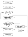
- This process is repeatedly executed by the number of images included in the image sequence as shown in S301. Specifically, it is determined whether a feature area is detected in the image (i) to be processed (S302). In the case of Yes in S302, the process proceeds to the detailed process of the identity determination shown in S303 to S306. On the other hand, in the case of No in S302, the identity determination process starting from the image (i) at that time is unnecessary, so the process returns from S307 to S301 and the process is performed on the image (i + 1) which is the next image. For example, in the case of FIG. 4, since the feature area FA1-1 is detected as shown in the image Y1 in the first image, the processing of S303 to S306 for searching for an image having the same feature area in the first image is performed. To be executed.
- the detected feature area is first estimated as an image (i + 1), which is an adjacent image, using deformation information (S303). Then, the deformation area obtained by deformation estimation and the feature area detected in the image (i + 1) are compared to determine whether they are the same (S304).
- step S304 if it is determined that the feature area between the deformation area and the adjacent image is not similar, the result of S304 is No, and the deformation estimation process and the identity determination process starting from the image (i) before incrementing in S302. Ends and returns from step S307 to step S301.
- FIG. 6 is a flowchart on the assumption that only one feature area is detected from one image. However, as shown in the image Y2 and the like of FIG. 4, a plurality of feature areas may be detected from one image. In that case, processing may be performed independently for each feature region.
- the feature areas FA1-2 and FA2-2 are detected as indicated by Y2.
- processing may be performed respectively by FA1-2 and FA2-2.
- FA1-2 since it is determined that FA1-2 is identical to the feature area FA1-1 detected in the previous image, it is not necessary to execute the process starting from FA1-2.
- FIG. 5 An example of processing for FA 2-2 is shown in FIG. Specifically, FA 2-2 is deformed and estimated using h (2, 3) to obtain FA ′ 2 ⁇ 2, and comparison processing of the feature area detected in image Y 3 with FA ′ 2 ⁇ 2 is performed. It is good.
- the image Y3 since the image Y3 has no feature area determined to be the same as FA'2-2, only the second image is set as the same feature area image group for the feature area FA2-2. Just do it.
- the process in consideration of FA2-4 of Y4 and FA2-5 of Y5 will be described later in the second embodiment.
- FIG. A flowchart in the case where a plurality of feature areas can be detected is shown in FIG. As in S301 and S307 of FIG. 6, S401 and S408 indicate that the process is repeated by the number of images included in the image sequence.
- a process of detecting a feature area is performed on an image (i) to be processed, as in S302 (S402). When no feature area is detected, the point is No in S402, and the process returns from S408 to S401 as in FIG.
- the process may be repeatedly executed for each area as shown in S404 and S406.
- the process to be executed for each area may be the same process as that shown in FIG. 6, and specifically, the same process as S303 to S306 (S405).
- a plurality of same feature area image groups overlap (a given image is a first same feature area image group as well as a second same feature area image The case is considered to be included in the group.
- the first identical feature area image group is the first to third images
- the second identical feature area image group is the second image.
- the representative images may be independently selected from the respective same feature area image groups. For example, in FIG. 4 and FIG. 5, if the first image is selected as a representative image from the first same feature area image group, and the second image is selected as a representative image from the second same feature area image group, OB1 Both are visible without loss of information in the summary image sequence.
- the representative image may be selected in consideration of the overlap of the same feature area image group.
- the second image which is the overlapping portion is used as a representative image
- the first and second same feature region image groups can be represented by one representative image. The effect of reducing the number of images is improved. That is, in addition to the area of the feature area, the position of the feature area in the image, the color information, the texture information, the reliability of the detection process, etc., in the representative image selection process, overlapping of a plurality of identical feature area image groups You may use information about
- the image processing apparatus acquires an image sequence having continuous first to N-th (N is an integer of 2 or more (including its value)) images.
- a sequence acquisition unit 101 a deformation information calculation unit 104 for obtaining deformation information representing deformation between two images in an image sequence, and a feature region for performing a process of detecting a feature region in each of the first to Nth images
- the detection unit 106 the i-th feature area which is the result of the detection process of the feature area in the i-th image, the (i + 1) -th feature area which is the result of the detection process of the feature area in the i + 1 th image
- An identity determination unit 109 that performs identity determination processing on the i-th feature area and the (i + 1) -th feature area based on h (i, i + 1) that is deformation information between the image and the (i + 1) -th image; Based on the result of the identity determination process, Including a summary processing unit 113 for performing image summarization process.
- the deformation information calculation unit 104 calculates an i-th deformation estimation target region including a region other than at least the i-th feature region in the i-th image, and a region other than at least the i + 1-th feature region in the i + 1 th image.
- H (i, i + 1) is determined based on the included i + 1 deformation estimation target region.
- the summary processing unit 113 in FIG. 1 corresponds to the image group setting unit 110 and the summary image sequence generation unit 111 as shown in FIG. 2, but the image group setting unit 110 and the summary image sequence generation unit Implementation of the abstract processing unit 113 is not hindered by the configuration other than 111.
- deformation information is obtained using a region including areas other than the feature region in the image (in a narrow sense, the entire image is not limited thereto) as a deformation estimation target region. That is, by obtaining the deformation of the area other than the feature area, the feature area included in the inside is also deformed in accordance with the deformation of the surrounding area. Therefore, the feature area in the deformation area obtained by such deformation processing By determining as a deformation area of, the identity is determined by comparing the detected feature area. This assumes that in the image targeted by this embodiment, the target area moves (sticks) in the same manner as the background, and deformation of the background is useful for estimating deformation of the feature area. It is.
- the image processing apparatus projects the i-th feature region onto the i + 1 th image based on the i-th feature region and h (i, i + 1). It may further include a deformation estimation processing unit 108 that performs deformation estimation processing for obtaining the i-th deformation region. Then, the sameness determination unit 109 determines the sameness between the ith feature area and the (i + 1) th feature area based on the ith deformation area obtained by the deformation estimation process and the (i + 1) th feature area. I do.
- the i-th feature area is FA 1-1 of the image Y 1 in FIG. 4
- the i-th deformation area corresponds to FA ′ 1-1 of the image Z 2 in FIG.
- a deformation area is obtained by estimating deformation of one feature area to the other image using deformation information, and the deformation area and the feature area of the other image It becomes possible to perform comparison processing.
- the deformation information is ideal information that does not contain an error
- a subject imaged in a given area of one image is imaged in which area of the other image by the deformation estimation process using the deformation information.
- the method of the present embodiment even if the subject is elastically deformed, it is possible to perform the sameness determination processing by a simple determination as to whether or not the two areas coincide. Thus, it is possible to perform determination with high accuracy. In addition, it is difficult to assume that the deformation information does not include an error, and considering that the color information and the texture information may fluctuate due to conditions of light quantity at the time of imaging, etc., the two areas do not match completely. It goes without saying that it is necessary to determine that they are the same if they are in a range close to a certain extent.
- the image string acquisition unit 101 may acquire a time-series in-vivo image as an image string. Then, the feature area detection unit 106 detects at least one of the lesion area and the abnormal mucous membrane area in the in-vivo image as a feature area.
- the lesion area represents an area having a characteristic corresponding to a given lesion in the image.
- the abnormal mucous membrane region represents a region corresponding to a mucous membrane which is not a lesion but has characteristics different from those of a normal mucous membrane.
- the feature area detection unit 106 may hold a model (pattern) representing a lesion area and detect the lesion area from the in-vivo image.
- a model representing a lesion area and a model representing an abnormal mucous membrane may be held to detect the lesion area and the abnormal mucous membrane region, respectively.
- a model representing a normal mucous membrane may be held, and an area other than the normal mucous membrane area in the image may be detected as either the lesion area or the abnormal mucous membrane area.
- the detection method of the feature area detection unit 106 can be variously modified.
- the lesion area or abnormal mucous membrane area which is the characteristic area integrally moves and deforms integrally with the normal mucous membrane area etc. which is the area (background) other than the characteristic area. That is, when the deformation estimation target area including areas other than the feature area is set, it becomes possible to accurately estimate the deformation of the feature area.
- the image quality of an in-vivo image captured by downsizing the imaging unit is smaller than that of a normal digital camera or the like from the viewpoint of invasiveness to a patient. Often low.
- the frame rate of imaging also becomes very low due to the limitation of the battery and the like.
- the capsule endoscope image has a particularly high degree of redundancy and further includes important feature areas such as a lesion area and an abnormal mucous membrane area
- viewing efficiency can be improved by displaying only the image in which these feature areas are detected.
- the number of images is large even with the image in which the feature area is detected. Since there are many images in which the same feature area is captured in these images, the images having the same feature area are classified into at least one group and then summarized into at least one image from each group The effect of improving the browsing efficiency is high, and it can be said that the method of the present embodiment is effective.
- the deformation information calculation unit 104 further includes an ith deformation estimation target region including at least a normal mucous membrane region in the i th image, and an ith + 1 deformation estimation target region including at least a normal mucous membrane region in the i + 1th image.
- the deformation information may be determined based on
- the deformation information calculation unit 104 may obtain an inter-image motion vector at at least one position in the image as deformation information. Then, the sameness determination unit 109 determines the i-th feature region and the i-th feature region based on the i-th feature region, the (i + 1) -th feature region, and the inter-image motion vector between the i-th image and the (i + 1) -th image. An identity determination process with the i + 1 feature area may be performed.
- deformation information in the present embodiment may be information that expresses deformation between images, and is not limited to motion vectors.
- the identity determination unit 109 is configured to project the i-th deformation region, which is a region obtained by projecting the i-th feature region using the h (i, i + 1) onto the i + 1 th image,
- the identity determination process may be performed based on at least one of shape information, color information, texture information, and position information in an image.
- the lesion type may be recognized together, and therefore, lesion type information may be used for the determination process of the identity. That is, the identity determination unit 109 determines whether the ith deformation area and the (i + 1) th feature area, which are areas obtained by projecting the ith feature area onto the (i + 1) th image using h (i, i + 1). The identity determination processing may be performed based on at least one of shape information, color information, texture information, position information in an image, and lesion type information.
- the identity determination process can be performed using, as a reference, shape information, color information, texture information, position information in the image, and the like of the deformation area and the feature area.
- lesion type information may be used in combination to perform the identity determination process.
- only one or a plurality of pieces of information may be used among the plurality of pieces of information.
- the positions and shapes are geometrically similar, there is a high possibility that they are the same feature area, so conditions for determining the identity of the shape information and the position information in the image It may be In addition, even if the position and shape are similar, it may not be appropriate to determine the same feature area if the textures are different, and therefore, the similarity of the textures is also combined to be the condition of the identity determination. It is also possible to make a high identity determination.
- texture information is used in the identity determination process, it is necessary to deform the texture by texture mapping or the like in the deformation estimation process in the deformation estimation processing unit 108. Conversely, if it is determined that the texture information is not used in the identity determination process, the deformation estimation process may be performed using only the shape (outline).
- the identity determination unit 109 may perform the identity determination process between the ith feature region and the (i + 1) th feature region based on the reliability of h (i, i + 1).
- the reliability of the deformation information calculation can also be used as a condition for determining the identity of the feature area, whereby the identity determination process can be performed with higher reliability. This is because the calculation reliability of the deformation information affects the accuracy of the deformation estimation process.
- the summary processing unit 113 determines, based on the result of the identity determination process, an image determined that the same feature area is captured among the first to N-th images. By selecting at least one representative image from the same feature area image group set by the image group setting unit 110 that sets the same feature area image group configured by the image group setting unit 110 and the image group setting unit 110 May be included.
- the same feature area image group is configured by an image including feature areas determined to be identical. That is, in the images included in the same feature area image group, information on the target feature area is overlapped. Therefore, by leaving one image from the same feature area image group and deleting another image, it is possible to reduce the number of images without losing information about the target feature area.
- the representative image to be selected is not limited to one. For example, in diagnosis of a lesion area, an image obtained by imaging the same lesion from different angles may be useful, etc. Therefore, even if a plurality of images are selected as representative images from the same feature area image group for a given feature area. Good.
- the summary processing unit 113 is configured to include area information of the feature area, color information of the feature area, texture information of the feature area, position information of the feature area in the image, and features in each image included in the same feature area image group.
- the representative image may be selected based on at least one piece of reliability information of the region detection process.
- the method of the present embodiment realizes the labor saving of the user (doctor), it is meaningless that the information on the feature area can not be sufficiently acquired from the image. That is, not only that the characteristic region is imaged, but also if the characteristic region is a detection result with sufficient reliability, or if the visibility in the image of the characteristic region is sufficient, etc. It is preferable to perform selection processing of a representative image.
- part or most of the processing may be realized by a program.
- the processor such as the CPU executes the program, whereby the image processing apparatus and the like of the present embodiment are realized.
- a program stored in a non-temporary information storage device is read, and a processor such as a CPU executes the read program.
- the information storage device (device readable by a computer) stores programs, data, etc., and its function is an optical disk (DVD, CD, etc.), HDD (hard disk drive), or memory (card type) This can be realized by a memory, a ROM, etc.
- a processor such as a CPU performs various processing of the present embodiment based on a program (data) stored in the information storage device. That is, a program for causing a computer (a device including an operation unit, a processing unit, a storage unit, and an output unit) to function as each unit of the present embodiment in the information storage device (a program for causing the computer to execute processing of each unit) Is stored.
- the image processing apparatus and the like of the present embodiment may include a processor and a memory.
- the processor here may be, for example, a CPU (Central Processing Unit). However, the processor is not limited to a CPU, and various processors such as a graphics processing unit (GPU) or a digital signal processor (DSP) can be used.
- the processor may also be a hardware circuit with an application specific integrated circuit (ASIC).
- the memory stores an instruction readable by a computer, and the instruction is executed by the processor to implement each unit such as the image processing apparatus according to the present embodiment.
- the memory here may be a semiconductor memory such as SRAM or DRAM, or may be a register or a hard disk.
- the instruction here may be an instruction of an instruction set that configures a program, or an instruction that instructs an operation to a hardware circuit of a processor.
- a deformation area obtained by estimating deformation of a feature area to an adjacent image is determined, and the comparison process of the deformation area and the feature area detected in the adjacent image is performed.
- the identity determination process for the feature area to be processed has been completed. Specifically, as shown in FIG. 4, when the feature area corresponding to FA′1-3 is not on Y4, the process for the feature area FA1-1 is completed.
- a feature corresponding to OB2 is detected if a feature area corresponding to OB2 is not detected in the middle even if the same subject is originally continued to be imaged. Processing for the area ends. This point is the same not only when the process of detecting the feature area fails, but also when the object OB2 disappears in the image X3 (the imaging itself can not be performed). Specifically, as shown in FIG. 5, the process for FA 2-2 ends when no feature area identical to FA 2-2 is found in Y 3. Therefore, although FA2-4 of Y4 and FA2-5 of Y5 are originally the same feature regions as FA2-2, they are determined to be feature regions different from F2-2.
- the second, fourth, and fifth images of FIG. 5 can be set as one identical feature area image group, they are divided into two identical feature area image groups. Therefore, the number of images selected as the representative image, that is, the number of images included in the summary image sequence is increased, and the effect of saving the labor of the user is reduced.
- the same number of the same for the given feature regions is provided by a predetermined number of sheets. Continue the sex determination process. In this way, even if the feature area can not be detected temporarily like Y3, the process for FA2-2 is continued for the fourth and fifth images, so FA2-2 And FA2-4 and FA2-5 can be determined to be identical.
- the sameness determination process of searching for an image having the same feature area as FA2-2 is started.
- deformation estimation is performed using FA ( 2-2) using h (2, 3), and FA (1) 2-2 is found as in the first embodiment.
- FA (1) 2-2 represents the same area as FA'2-2 in FIG.
- FIG. 5 it is determined that the image Y3 does not have the same feature area as FA (1) 2-2.
- the process is not ended here, and in the next image, it is determined whether or not there is the same feature area as FA2-2. However, since the feature area corresponding to OB2 is not detected in Y3, the feature area actually detected in the third image can not be deformed and estimated with respect to the fourth image.
- the characteristic area FA2-2 is deformed and projected onto the fourth image, and comparison processing with the characteristic area detected at Y4 is performed.
- a region where FA2-2 is projected to the fourth image can be obtained from deformation information h (2, 4) between X2 and X4 and FA2-2.
- deformation information between any two images can be expressed by a combination of deformation information between adjacent images.
- the required area for the case where FA2-2 is deformed by h (2, 4) and the case where FA2-2 is further deformed by h (2, 3) and then h (3, 4) are It should be equal.
- the area obtained by deforming FA 2-2 with h (2, 3) is already obtained as the deformation area FA (1) 2-2, so that FA (1) 2-2 is h (3, 4). Transform it and find FA (2) 2-2.
- the search is performed for a predetermined number of sheets.
- the threshold Th is set, the same feature area is found up to the i-th image, and the same feature area is not found in the (i + 1) th and subsequent ones.
- the same identity determination process may be continued from the image.
- FAi which is a feature area in the i-th image is sequentially deformed by deformation information, and FA (1) i, FA (2) i,... FA (Th) i are obtained and detected. Compare with feature regions.
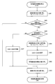
- FIG. 9 shows a flowchart for explaining the process of this embodiment.
- S501 and S513 indicate that the processing is repeated by the number of images included in the image sequence, as in S301 and S307. The same applies to S502 and S503 as in S302 and S303.
- S504 processing of comparing the deformation area and the feature area detected in the adjacent image is performed. If the deformation area and the feature area detected in the adjacent image are the same, the result of S504 is Yes, and the processes of S505 and S506 are performed. This is similar to the processing of S305 and S306 in FIG.
- the result in S509 is Yes, and the adjacent image (i + 1) at that time is identical as having the same feature area as the image (i) at the time of S502.
- a feature area image group is set (S510). Then, i is incremented (S 511), and the process returns to S 503 in order to continue the identity determination process.
- the process of S507 and subsequent processes is compared with the deformation cumulative threshold (S512). If the number of searched sheets is equal to or less than the threshold value, the process returns to S507, and the processing is continued for the next image. If the number of searched sheets exceeds the threshold, the process returns from step S513 to step S501, and the image serving as the starting point of the process is updated.
- a plurality of feature areas may be detected from one image.
- processing may be performed in parallel for each feature area as in the first embodiment.
- the flowchart is the same as that in FIG. 7, and the processing in S405 and S407 may be changed to the processing in the second embodiment, that is, the processing in S503 to S512 in FIG.
- deformation estimation is cumulatively performed on the deformation area by the set number of threshold values. Therefore, if the sameness determination condition with the feature regions detected within the threshold number of sheets is satisfied, the same for the discontinuous image even if the feature region detection is not continuously performed.
- a feature area image group can be set.
- the identity determining unit 109 determines the predetermined number of images based on the deformation information. The process may be continued, and the identity determination process may be performed when the feature area is detected in the set number of images or less.
- the same feature area as FA 2-2 is not detected from the third image by comparison of the feature areas detected by FA (1) 2-2 of Z 3 and Y 3 in the example of FIG. Also in this case, processing regarding FA2-2 is continued, and identity determination processing using FA (2) 2-2 of Z4 and FA2-4 detected by Y4 in the fourth image is performed. .
- the process is ended there. It is possible to continue the identity determination process using the next image without performing the process.
- the processing for FA2-2 ends with the third image, and the identity determination processing for FA2-4 and FA2-5 that should be originally identical is a row. I can not do it. Therefore, the same feature area image group having the same feature area as the second image is only the second image, and the reduction effect of the number of images may be reduced.
- identity determination processing is performed between FA 2-2, FA 2-4, and FA 2-5. Therefore, since the second, fourth, and fifth images are set as the same feature area image group, the reduction effect of the number of images is improved as compared with the method of the first embodiment, and it is possible to further save labor of the user. become.
- the sex determination unit 109 is the deformation information between the ith characteristic area and the (i + 2) th characteristic area which is the result of the detection processing of the characteristic area in the (i + 2) th image and the ith image and the (i + 2) th image.
- the identity determination process may be performed between the ith feature area and the (i + 2) th feature area based on h (i, i + 2).
- a deformation area (FA (2) 2-2) is obtained by estimating the deformation of the i-th feature area (for example, FA2-2 in FIG. 8) with respect to the image two points ahead, and The comparison process may be performed with the feature area (FA2-4) detected in the image two ahead.
- the process of obtaining FA (2) 2-2 does not have to be performed using FA 2-2 and h (2, 4), and the already obtained FA (1) 2-2 is h It may be carried out by estimating deformation according to (3, 4). That is, in a narrow sense, the deformation estimation processing unit 108 of the image processing apparatus determines the (i + 1) th deformation region based on the (i + 1) th deformation information which is the deformation information between the (i + 1) th image and the (i + 2) th image.
- the identity determination process is performed to determine the identity of the i-th feature area and the (i + 2) -th feature area based on the i + 2th feature area that is the result of the area detection process. May be
- the sameness determination unit 109 does not determine that the ith feature area is the same as the ith feature area which is the result of the process of detecting the feature area in the ith feature area and the ith + k (k is an integer) image.
- the identity determination process on the i-th feature area may be ended.
- the sameness determination unit 109 determines that the i-th feature region and the (i + k) -th feature region are not the same, and if k ⁇ Th, , Based on h (i, i + k + 1), which is the deformation information between the i-th image and the i + k + 1 image, which is a result of the detection process of the feature region in the i + k + 1 image; An identity determination process may be performed between the i feature region and the (i + k + 1) feature region.
- the processing in the case where the same feature area can not be found is not limited to the image two images ahead, and it is possible to continue the images ahead by a predetermined number (Th in the above example). .
- Th a predetermined number
- the detection of the feature area may be possible if the imaging conditions change.
- the feature area is shielded by the contents, the eyebrow structure, etc., the contents are moved (in a narrow sense, removed), or the eyebrow structure moves by its own movement, or the like.
- processing unit 101 image sequence acquisition unit, 102 image input unit, 103 image database, 104 deformation information calculation unit, 105 deformation information storage unit, 106 feature region detection unit, 107 feature region storage unit, 108 deformation estimation processing unit, 109 identity determination unit 110 image group setting unit 111 summary image sequence generation unit 112 output unit, 113 summary processing unit
Abstract
L'invention concerne un dispositif de traitement d'image comprenant : une unité d'acquisition de séries d'images (101) ; une unité de calcul d'information de modification (104) qui dérive l'information de modification entre les images ; une unité de détection d'une région caractéristique (106) qui effectue un procédé de détection d'une région caractéristique ; une unité de détermination d'identité (109) qui effectue, sur base de l'information de modification entre la ième image et la i+1ième image, un procédé de détermination d'identité d'une ième région caractéristique et d'une i+1ème région caractéristique ; et une unité de traitement de soustraction (113) qui effectue un procédé de soustraction d'images. L'unité de calcul de l'information de modification (104) dérive l'information de modification sur base d'une ième région d'estimation de modification du sujet qui inclut une région dans la ième image autre que la ième région caractéristique et une i+1ème région d'estimation de modification du sujet qui comprend une région dans la i+1ème image autre que la i+1ème région caractéristique.
Priority Applications (3)
| Application Number | Priority Date | Filing Date | Title |
|---|---|---|---|
| EP14831513.8A EP3028624A4 (fr) | 2013-08-02 | 2014-05-20 | Dispositif de traitement d'image, procédé de traitement d'image, et programme |
| CN201480042666.1A CN105407787B (zh) | 2013-08-02 | 2014-05-20 | 图像处理装置、图像处理方法 |
| US15/012,281 US9898664B2 (en) | 2013-08-02 | 2016-02-01 | Image processing device, image processing method, and information storage device |
Applications Claiming Priority (2)
| Application Number | Priority Date | Filing Date | Title |
|---|---|---|---|
| JP2013-161029 | 2013-08-02 | ||
| JP2013161029A JP6188477B2 (ja) | 2013-08-02 | 2013-08-02 | 画像処理装置、画像処理方法及びプログラム |
Related Child Applications (1)
| Application Number | Title | Priority Date | Filing Date |
|---|---|---|---|
| US15/012,281 Continuation US9898664B2 (en) | 2013-08-02 | 2016-02-01 | Image processing device, image processing method, and information storage device |
Publications (1)
| Publication Number | Publication Date |
|---|---|
| WO2015015869A1 true WO2015015869A1 (fr) | 2015-02-05 |
Family
ID=52431415
Family Applications (1)
| Application Number | Title | Priority Date | Filing Date |
|---|---|---|---|
| PCT/JP2014/063283 WO2015015869A1 (fr) | 2013-08-02 | 2014-05-20 | Dispositif de traitement d'image, procédé de traitement d'image, et programme |
Country Status (5)
| Country | Link |
|---|---|
| US (1) | US9898664B2 (fr) |
| EP (1) | EP3028624A4 (fr) |
| JP (1) | JP6188477B2 (fr) |
| CN (1) | CN105407787B (fr) |
| WO (1) | WO2015015869A1 (fr) |
Families Citing this family (18)
| Publication number | Priority date | Publication date | Assignee | Title |
|---|---|---|---|---|
| US10235750B2 (en) * | 2014-02-27 | 2019-03-19 | Agency For Science, Technology And Research | Segmentation of cardiac magnetic resonance (CMR) images using a memory persistence approach |
| JP6371544B2 (ja) * | 2014-03-14 | 2018-08-08 | オリンパス株式会社 | 画像処理装置、画像処理方法、及び画像処理プログラム |
| JP6821303B2 (ja) * | 2015-12-15 | 2021-01-27 | キヤノン株式会社 | 情報処理装置、情報処理方法およびプログラム |
| CN109475278A (zh) * | 2016-07-25 | 2019-03-15 | 奥林巴斯株式会社 | 图像处理装置、图像处理方法和程序 |
| WO2018052966A1 (fr) * | 2016-09-16 | 2018-03-22 | Zimmer, Inc. | Guidage de technique chirurgicale à réalité augmentée |
| EP3596658A1 (fr) | 2017-03-13 | 2020-01-22 | Zimmer, Inc. | Guidage de diagnostic de réalité augmentée |
| JP6785948B2 (ja) * | 2017-03-30 | 2020-11-18 | 富士フイルム株式会社 | 医療用画像処理装置及び内視鏡システム並びに医療用画像処理装置の作動方法 |
| US20180307912A1 (en) * | 2017-04-20 | 2018-10-25 | David Lee Selinger | United states utility patent application system and method for monitoring virtual perimeter breaches |
| EP3636134A4 (fr) * | 2017-05-25 | 2021-03-10 | Nec Corporation | Dispositif de traitement d'informations, procédé de commande et programme |
| US11432877B2 (en) | 2017-08-02 | 2022-09-06 | Medtech S.A. | Surgical field camera system that only uses images from cameras with an unobstructed sight line for tracking |
| CN111050628B (zh) | 2017-09-15 | 2022-09-06 | 富士胶片株式会社 | 医疗图像处理装置 |
| JPWO2019078237A1 (ja) * | 2017-10-18 | 2020-10-22 | 富士フイルム株式会社 | 医療画像処理装置、内視鏡システム、診断支援装置、並びに医療業務支援装置 |
| CN108615045B (zh) * | 2018-03-06 | 2022-07-12 | 重庆金山医疗技术研究院有限公司 | 筛选胶囊内镜拍摄的图像的方法、装置及设备 |
| JP7368074B2 (ja) * | 2018-03-28 | 2023-10-24 | 日本光電工業株式会社 | 挿管装置 |
| JP7135082B2 (ja) | 2018-05-17 | 2022-09-12 | 富士フイルム株式会社 | 内視鏡装置、内視鏡装置の作動方法、及びプログラム |
| JP7215504B2 (ja) * | 2019-02-13 | 2023-01-31 | 日本電気株式会社 | 施術支援装置、施術支援方法、及びプログラム |
| CN111879648A (zh) * | 2020-07-24 | 2020-11-03 | 三峡大学 | 一种弹性模量的校准方法 |
| JP7110293B2 (ja) * | 2020-09-28 | 2022-08-01 | 楽天グループ株式会社 | 情報処理装置、情報処理方法およびプログラム |
Citations (6)
| Publication number | Priority date | Publication date | Assignee | Title |
|---|---|---|---|---|
| JP2006320650A (ja) * | 2005-05-20 | 2006-11-30 | Olympus Medical Systems Corp | 画像表示装置 |
| JP2007257287A (ja) | 2006-03-23 | 2007-10-04 | Tokyo Institute Of Technology | 画像レジストレーション方法 |
| JP2008217714A (ja) | 2007-03-07 | 2008-09-18 | Sogo Keibi Hosho Co Ltd | 追跡装置、追跡方法、及び追跡プログラム |
| JP2009268005A (ja) | 2008-04-30 | 2009-11-12 | Meidensha Corp | 侵入物検知追跡装置 |
| JP2010113616A (ja) | 2008-11-07 | 2010-05-20 | Olympus Corp | 画像処理装置、画像処理プログラムおよび画像処理方法 |
| JP2010158308A (ja) * | 2009-01-06 | 2010-07-22 | Olympus Corp | 画像処理装置、画像処理方法および画像処理プログラム |
Family Cites Families (2)
| Publication number | Priority date | Publication date | Assignee | Title |
|---|---|---|---|---|
| JP2007195586A (ja) * | 2006-01-23 | 2007-08-09 | Olympus Medical Systems Corp | カプセル型医療装置、医療用制御装置、医療用画像処理装置及びプログラム |
| JP5374135B2 (ja) * | 2008-12-16 | 2013-12-25 | オリンパス株式会社 | 画像処理装置、画像処理装置の作動方法および画像処理プログラム |
-
2013
- 2013-08-02 JP JP2013161029A patent/JP6188477B2/ja not_active Expired - Fee Related
-
2014
- 2014-05-20 CN CN201480042666.1A patent/CN105407787B/zh not_active Expired - Fee Related
- 2014-05-20 EP EP14831513.8A patent/EP3028624A4/fr not_active Withdrawn
- 2014-05-20 WO PCT/JP2014/063283 patent/WO2015015869A1/fr active Application Filing
-
2016
- 2016-02-01 US US15/012,281 patent/US9898664B2/en active Active
Patent Citations (6)
| Publication number | Priority date | Publication date | Assignee | Title |
|---|---|---|---|---|
| JP2006320650A (ja) * | 2005-05-20 | 2006-11-30 | Olympus Medical Systems Corp | 画像表示装置 |
| JP2007257287A (ja) | 2006-03-23 | 2007-10-04 | Tokyo Institute Of Technology | 画像レジストレーション方法 |
| JP2008217714A (ja) | 2007-03-07 | 2008-09-18 | Sogo Keibi Hosho Co Ltd | 追跡装置、追跡方法、及び追跡プログラム |
| JP2009268005A (ja) | 2008-04-30 | 2009-11-12 | Meidensha Corp | 侵入物検知追跡装置 |
| JP2010113616A (ja) | 2008-11-07 | 2010-05-20 | Olympus Corp | 画像処理装置、画像処理プログラムおよび画像処理方法 |
| JP2010158308A (ja) * | 2009-01-06 | 2010-07-22 | Olympus Corp | 画像処理装置、画像処理方法および画像処理プログラム |
Non-Patent Citations (1)
| Title |
|---|
| See also references of EP3028624A4 |
Also Published As
| Publication number | Publication date |
|---|---|
| US20160148053A1 (en) | 2016-05-26 |
| US9898664B2 (en) | 2018-02-20 |
| EP3028624A1 (fr) | 2016-06-08 |
| JP2015032127A (ja) | 2015-02-16 |
| JP6188477B2 (ja) | 2017-08-30 |
| EP3028624A4 (fr) | 2017-06-21 |
| CN105407787B (zh) | 2017-10-10 |
| CN105407787A (zh) | 2016-03-16 |
Similar Documents
| Publication | Publication Date | Title |
|---|---|---|
| WO2015015869A1 (fr) | Dispositif de traitement d'image, procédé de traitement d'image, et programme | |
| US10860930B2 (en) | Learning method, image recognition device, and computer-readable storage medium | |
| JP5080485B2 (ja) | 画像処理装置、画像処理方法、および画像処理プログラム | |
| US8290280B2 (en) | Image processing device, image processing method, and computer readable storage medium storing image processing program | |
| KR102237441B1 (ko) | 뉴럴 네트워크를 이용하여 캡슐 내시경 영상으로부터 병변 판독 방법 및 장치 | |
| JP6125648B2 (ja) | 生体情報取得装置および生体情報取得方法 | |
| WO2013157354A1 (fr) | Dispositif de traitement d'image, programme et procédé de traitement d'image | |
| US11954860B2 (en) | Image matching method and device, and storage medium | |
| WO2021103938A1 (fr) | Procédé, appareil et dispositif de traitement d'images médicales, support et endoscope | |
| JP6248780B2 (ja) | 脈波検出装置、脈波検出方法及び脈波検出プログラム | |
| US20220369920A1 (en) | Phase identification of endoscopy procedures | |
| JP7266599B2 (ja) | 患者の身体運動を検知するためのデバイス、システム及び方法 | |
| CN110769731B (zh) | 内窥镜系统、内窥镜用处理系统、图像处理方法 | |
| KR20130013966A (ko) | 이미지 정합 기반 흉부영상 진단 시스템 및 방법 | |
| Figueiredo et al. | Dissimilarity measure of consecutive frames in wireless capsule endoscopy videos: a way of searching for abnormalities | |
| JP7100505B2 (ja) | 画像処理装置、画像処理装置の作動方法、及び画像処理装置の作動プログラム | |
| CN114255200A (zh) | 基于实时电影成像的心肌应力分析方法及装置 | |
| WO2023126999A1 (fr) | Dispositif de traitement d'image, procédé de traitement d'image et support de stockage | |
| JP5973783B2 (ja) | 画像処理装置、プログラム及び画像処理方法 | |
| WO2021149169A1 (fr) | Dispositif d'aide au fonctionnement, procédé d'aide au fonctionnement et support d'enregistrement lisible par ordinateur | |
| WO2023068372A1 (fr) | Dispositif de mesure de mouvement thoracique, programme de mesure de mouvement thoracique et support de stockage non temporaire | |
| US20210304409A1 (en) | Image processing apparatus, image processing method, and storage medium | |
| Khajarian et al. | Image-based Live Tracking and Registration for AR-Guided Liver Surgery Using Hololens2: A Phantom Study | |
| US20220160260A1 (en) | System and method for measuring biomedical signal | |
| JP2019098168A (ja) | 肌解析方法及び肌解析システム |
Legal Events
| Date | Code | Title | Description |
|---|---|---|---|
| WWE | Wipo information: entry into national phase |
Ref document number: 201480042666.1 Country of ref document: CN |
|
| 121 | Ep: the epo has been informed by wipo that ep was designated in this application |
Ref document number: 14831513 Country of ref document: EP Kind code of ref document: A1 |
|
| NENP | Non-entry into the national phase |
Ref country code: DE |
|
| WWE | Wipo information: entry into national phase |
Ref document number: 2014831513 Country of ref document: EP |