WO2015015819A1 - 熱式流量計 - Google Patents
熱式流量計 Download PDFInfo
- Publication number
- WO2015015819A1 WO2015015819A1 PCT/JP2014/052602 JP2014052602W WO2015015819A1 WO 2015015819 A1 WO2015015819 A1 WO 2015015819A1 JP 2014052602 W JP2014052602 W JP 2014052602W WO 2015015819 A1 WO2015015819 A1 WO 2015015819A1
- Authority
- WO
- WIPO (PCT)
- Prior art keywords
- flow rate
- resistor
- circuit
- flow meter
- integrated circuit
- Prior art date
- Legal status (The legal status is an assumption and is not a legal conclusion. Google has not performed a legal analysis and makes no representation as to the accuracy of the status listed.)
- Ceased
Links
Images





Classifications
-
- G—PHYSICS
- G01—MEASURING; TESTING
- G01F—MEASURING VOLUME, VOLUME FLOW, MASS FLOW OR LIQUID LEVEL; METERING BY VOLUME
- G01F1/00—Measuring the volume flow or mass flow of fluid or fluent solid material wherein the fluid passes through a meter in a continuous flow
- G01F1/68—Measuring the volume flow or mass flow of fluid or fluent solid material wherein the fluid passes through a meter in a continuous flow by using thermal effects
- G01F1/696—Circuits therefor, e.g. constant-current flow meters
- G01F1/6965—Circuits therefor, e.g. constant-current flow meters comprising means to store calibration data for flow signal calculation or correction
-
- G—PHYSICS
- G01—MEASURING; TESTING
- G01F—MEASURING VOLUME, VOLUME FLOW, MASS FLOW OR LIQUID LEVEL; METERING BY VOLUME
- G01F1/00—Measuring the volume flow or mass flow of fluid or fluent solid material wherein the fluid passes through a meter in a continuous flow
- G01F1/68—Measuring the volume flow or mass flow of fluid or fluent solid material wherein the fluid passes through a meter in a continuous flow by using thermal effects
- G01F1/684—Structural arrangements; Mounting of elements, e.g. in relation to fluid flow
- G01F1/6842—Structural arrangements; Mounting of elements, e.g. in relation to fluid flow with means for influencing the fluid flow
-
- G—PHYSICS
- G01—MEASURING; TESTING
- G01F—MEASURING VOLUME, VOLUME FLOW, MASS FLOW OR LIQUID LEVEL; METERING BY VOLUME
- G01F1/00—Measuring the volume flow or mass flow of fluid or fluent solid material wherein the fluid passes through a meter in a continuous flow
- G01F1/68—Measuring the volume flow or mass flow of fluid or fluent solid material wherein the fluid passes through a meter in a continuous flow by using thermal effects
- G01F1/684—Structural arrangements; Mounting of elements, e.g. in relation to fluid flow
- G01F1/6845—Micromachined devices
-
- G—PHYSICS
- G01—MEASURING; TESTING
- G01F—MEASURING VOLUME, VOLUME FLOW, MASS FLOW OR LIQUID LEVEL; METERING BY VOLUME
- G01F1/00—Measuring the volume flow or mass flow of fluid or fluent solid material wherein the fluid passes through a meter in a continuous flow
- G01F1/68—Measuring the volume flow or mass flow of fluid or fluent solid material wherein the fluid passes through a meter in a continuous flow by using thermal effects
- G01F1/684—Structural arrangements; Mounting of elements, e.g. in relation to fluid flow
- G01F1/688—Structural arrangements; Mounting of elements, e.g. in relation to fluid flow using a particular type of heating, cooling or sensing element
- G01F1/69—Structural arrangements; Mounting of elements, e.g. in relation to fluid flow using a particular type of heating, cooling or sensing element of resistive type
- G01F1/692—Thin-film arrangements
-
- G—PHYSICS
- G01—MEASURING; TESTING
- G01P—MEASURING LINEAR OR ANGULAR SPEED, ACCELERATION, DECELERATION, OR SHOCK; INDICATING PRESENCE, ABSENCE, OR DIRECTION, OF MOVEMENT
- G01P5/00—Measuring speed of fluids, e.g. of air stream; Measuring speed of bodies relative to fluids, e.g. of ship, of aircraft
- G01P5/10—Measuring speed of fluids, e.g. of air stream; Measuring speed of bodies relative to fluids, e.g. of ship, of aircraft by measuring thermal variables
- G01P5/12—Measuring speed of fluids, e.g. of air stream; Measuring speed of bodies relative to fluids, e.g. of ship, of aircraft by measuring thermal variables using variation of resistance of a heated conductor
Definitions
- the present invention relates to a thermal flow meter.
- a thermal flow meter that measures the flow rate of air includes a flow rate detection element for measuring the air flow rate, and performs heat transfer between the flow rate detection element and the gas that is a measurement target, thereby providing a gas air It is configured to measure the flow rate.
- the air flow rate measured by the thermal flow meter is widely used as an important control parameter for various devices.
- the feature of the thermal type flow meter is that the flow rate of air can be measured with relatively high accuracy compared to other types of flow meters.
- a thermal flow meter that measures the amount of intake air that is guided to an internal combustion engine includes a sub-passage that takes in a portion of the intake air amount and a flow rate detection element disposed in the sub-passage, and the flow rate detection element is connected to the gas to be measured. By performing heat transfer between them, the state of the gas to be measured flowing through the auxiliary passage is measured, and an electric signal representing the amount of intake air introduced to the internal combustion engine is output.
- Patent Document 1 includes “a substrate, a diaphragm formed on the substrate, a heating resistor and a temperature detection resistor formed on the diaphragm, and heats the heating resistor.
- strain detection resistors are formed upstream and downstream of the flow of the fluid to be measured with respect to the heating resistor on the diaphragm.
- a technique is disclosed in which the amount of distortion generated on the diaphragm by the resistor is detected, and the flow signal detected by the heating resistor and the temperature detection resistor is compensated based on the detected amount of distortion.
- an integrated circuit for example, an LSI that calculates the flow rate of the gas to be measured based on the output signal from the flow rate detection element.
- an integrated circuit for example, an LSI
- thermal stress acting on the thermal flow meter for example, thermal stress generated in an adhesive or resin for fixing the casing or integrated circuit to the substrate to accommodate the substrate.
- the output of the LSI arranged in the sensor assembly may fluctuate, and the measurement accuracy of the thermal flow meter may be reduced.
- the present invention has been made in view of the above points, and the object of the present invention is even when distortion caused by thermal stress occurs in the integrated circuit that calculates the flow rate of the gas to be measured.
- An object of the present invention is to provide a thermal flow meter that can suppress variations in measurement accuracy.
- the thermal flow meter performs heat transfer between the sub-passage for flowing the gas to be measured taken from the main passage and the gas to be measured flowing through the sub-passage. And a flow rate detecting element for measuring the flow rate of the gas to be measured.
- the thermal flow meter has a circuit package in which a flow rate detection element and an integrated circuit that calculates a flow rate of a gas to be measured based on an output signal from the flow rate detection element are mounted, and a sub-passage that accommodates the circuit package. A formed casing.
- the integrated circuit includes an analog circuit having a resistor, detects the amount of distortion generated in the resistor at a position adjacent to the resistor of the analog circuit, and outputs the analog circuit based on the amount of distortion or Correct the flow rate value of the gas to be measured.
- variation in measurement accuracy can be suppressed even when distortion due to thermal stress occurs in the integrated circuit that calculates the flow rate of the gas to be measured.
- FIG. 1 is a system diagram showing an embodiment in which a thermal flow meter is used as an electronic fuel injection internal combustion engine control system as a thermal flow meter according to the present invention.
- the top view of the circuit package which comprises the thermal type flow meter which concerns on this embodiment.
- the top view of the thermal type flow meter which concerns on this embodiment.
- FIG. 4 is a cross-sectional view taken along line AA in FIG. 3.
- the circuit block diagram of the thermal type flow meter which concerns on 1st Embodiment.
- FIG. 1 is a system diagram showing an embodiment in which a thermal flow meter is used as an electronic fuel injection internal combustion engine control system as a thermal flow meter according to the present invention.
- a thermal flow meter is used as an electronic fuel injection internal combustion engine control system as a thermal flow meter according to the present invention.
- an internal combustion engine 110 including an engine cylinder 112 and an engine piston 114
- intake air is sucked from an air cleaner 122 as a measured gas IA.
- the sucked measurement gas IA is led to the combustion chamber of the engine cylinder 112 through, for example, an intake body including the intake pipe 71 in which the main passage 70 is formed, a throttle body 126, and an intake manifold 128.
- the flow rate of the gas to be measured IA that is the intake air led to the combustion chamber is measured by the thermal flow meter 10 according to the present embodiment, and fuel is supplied from the fuel injection valve 152 based on the measured flow rate. Together with the gas to be measured IA, which is introduced into the combustion chamber in the state of the air-fuel mixture.
- the fuel injection valve 152 is provided at the intake port of the internal combustion engine, and the fuel injected into the intake port forms an air-fuel mixture together with the measured gas IA that is intake air, and is connected via the intake valve 116. It is guided to the combustion chamber and burns to generate mechanical energy.
- the thermal flow meter 10 can be used not only for the method of injecting fuel into the intake port of the internal combustion engine shown in FIG. 1 but also for the method of directly injecting fuel into each combustion chamber.
- the basic concept of the control parameter measurement method including the method of using the thermal flow meter 10 and the control method of the internal combustion engine including the fuel supply amount and the ignition timing is substantially the same.
- a method of injecting fuel into the port is shown in FIG.
- the fuel and air guided to the combustion chamber are in a mixed state of fuel and air, and are ignited explosively by spark ignition of the spark plug 154 to generate mechanical energy.
- the combusted gas is guided from the exhaust valve 118 to the exhaust pipe, and is exhausted from the exhaust pipe to the outside as exhaust EA.
- the flow rate of the gas to be measured IA that is the intake air led to the combustion chamber is controlled by a throttle valve 132 whose opening degree changes based on the operation of the accelerator pedal.
- the fuel supply amount is controlled based on the flow rate of the intake air guided to the combustion chamber, and the driver controls the flow rate of the intake air guided to the combustion chamber by controlling the opening degree of the throttle valve 132 so that the internal combustion engine is controlled.
- the generated mechanical energy can be controlled.
- the flow rate, humidity, and temperature of the measurement target gas IA that is the intake air that is taken in from the air cleaner 122 and flows through the main passage 70 are measured by the thermal flow meter 10, and the flow rate, humidity, and temperature of the intake air are measured from the thermal flow meter 10.
- the electric signal to be represented is input to the control device 200.
- the output of the throttle angle sensor 144 that measures the opening degree of the throttle valve 132 is input to the control device 200, and the positions and states of the engine piston 114, the intake valve 116, and the exhaust valve 118 of the internal combustion engine, and the rotation of the internal combustion engine.
- the output of the rotation angle sensor 146 is input to the control device 200.
- the output of the oxygen sensor 148 is input to the control device 200.
- the control device 200 calculates the fuel injection amount and the ignition timing based on the flow rate, humidity, and temperature of the intake air, which is the output of the thermal flow meter 10, and the rotational speed of the internal combustion engine from the rotation angle sensor 146. Based on these calculation results, the amount of fuel supplied from the fuel injection valve 152 and the ignition timing ignited by the spark plug 154 are controlled. The fuel supply amount and ignition timing are actually based on the intake air temperature and throttle angle change state measured by the thermal flow meter 10, the engine rotational speed change state, and the air-fuel ratio state measured by the oxygen sensor 148. Are controlled. The control device 200 further controls the amount of air that bypasses the throttle valve 132 by the idle air control valve 156 in the idle operation state of the internal combustion engine, thereby controlling the rotational speed of the internal combustion engine in the idle operation state.
- Both the fuel supply amount and ignition timing, which are the main control amounts of the internal combustion engine, are calculated using the output of the thermal flow meter 10 as a main parameter. Accordingly, improvement in measurement accuracy of the thermal flow meter 10, suppression of changes over time, and improvement in reliability are important in terms of improvement in vehicle control accuracy and ensuring reliability.
- improvement in measurement accuracy of the thermal flow meter 10 suppression of changes over time, and improvement in reliability are important in terms of improvement in vehicle control accuracy and ensuring reliability.
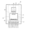
- FIG. 2 is a plan view of a circuit package constituting the thermal flow meter 10 according to the present embodiment.
- a circuit package 20 constituting the thermal flow meter 10 according to the present embodiment includes a flow rate detecting element 24 and an integrated circuit (LSI) 23 that is a calculation unit.
- the integrated circuit (LSI) 23 and the flow rate detection element 24 described above are bonded to a metal lead frame 21 via an adhesive sheet 26.
- the integrated circuit 23 and the flow rate detection element 24 and the integrated circuit 23 and the lead frame 21 are electrically connected by wire bonding using gold wires 28 and 29. Thereafter, these are molded with a first resin 27 (polymer resin) which is a thermosetting resin, and formed into a circuit package 20. As a result, the integrated circuit 23 is covered with the first resin 27.
- a first resin 27 polymer resin
- the integrated circuit 23 controls the flow rate detection element 24 that is a sensor chip, converts an analog signal from the flow rate detection element 24 into a digital signal, calculates the flow rate of the gas IA to be measured, and outputs it to the outside. It is configured as follows. Details of the flow rate detection element 24 and the integrated circuit 23 will be described later with reference to FIG.
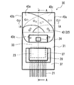
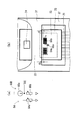
- FIG. 3 is a plan view of the thermal type flow meter according to this embodiment
- FIG. 4 is a cross-sectional view taken along line AA in FIG.
- FIG. 3 is a view showing a state in which the front cover 41 and the back cover 42 of the thermal flow meter 10 are removed.
- the thermal flow meter 10 is attached to the circuit package 20 described above, a housing 31 in which the circuit package 20 is fixedly accommodated, and a front surface and a back surface of the housing 31.
- the front cover 41 and the back cover 42 are provided (see FIG. 4).
- the circuit package 20 shown in FIG. 2 is accommodated in the casing 30.
- the front cover 41 and the rear cover 42 are attached to the front surface and the rear surface of the housing 31, thereby forming the casing 30 that fixes and accommodates the circuit package 20.
- the housing 31 has a sub-passage groove 32 for guiding the gas to be measured flowing through the main passage 70 to the flow rate detection element 24.
- the sub-passage groove 32 is formed on the front surface and the back surface of the housing 31, and covers the front cover 41 on the front surface side of the housing 31 and covers the back cover 42 on the back surface side thereof.
- a sub-passage 43 for flowing the gas to be measured taken from is formed.
- the sub passage 43 has an inlet 43a formed on the side surface of the casing 30 facing the upstream side of the main passage 70, and an outlet 43b formed on the side surface of the casing 30 facing the downstream side thereof.
- the gas to be measured taken from the inlet 43a of the sub passage 43 passes through the back side sub passage 43c formed on the back side.
- the gas to be measured IA that has passed through the back side sub-passage 43c passes through the flow rate detecting element 24 disposed in the through portion 43d that penetrates the front and back surfaces, and the gas to be measured that has passed through the through portion 43d is formed on the front side. Passes through the front side sub-passage 43e and flows out from the outlet 43b.
- the housing 31 is integrally formed with a thermoplastic resin (second resin) 37 in a state where the circuit package 20 is disposed in the mold.
- a holding portion 33 that holds (fixes) the circuit package 20 is formed in a part of the sub-passage groove 32.
- the holding portion 33 holds the circuit package 20 so as to circulate around the circuit package 20, and the flow rate detection element 24 is disposed in the auxiliary passage groove 32 (through portion 43 d).
- the holding portion 33 of the casing 30 holds the circuit package 20 between or on the integrated circuit (LSI) 23 and the integrated circuit (LSI) 23, and at the same time with respect to the sub-passage 43 with high accuracy.
- the detection element 23 can be arranged.
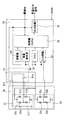
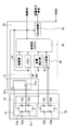
- FIG. 5 is a circuit configuration diagram of the thermal type flow meter according to the first embodiment.
- FIG. 6 is a diagram for explaining the strain amount detection unit of the thermal flow meter according to the first embodiment
- FIG. 6A is a diagram for explaining the circuit configuration of the strain amount detection unit.
- (b) is a diagram for explaining a constant current circuit of the strain amount detection unit
- (c) is a diagram for explaining an arrangement state of resistors constituting the strain amount detection unit.
- FIG. 7 is a view for explaining correction of the thermal type flow meter according to the first embodiment.
- the flow rate detection element 24 measures a general thermal flow rate, and performs heat transfer with the gas to be measured IA flowing through the sub-passage 43, thereby reducing the flow rate of the gas to be measured IA. measure.
- the flow rate detecting element 24 forms a diaphragm 24a on a flat plate substrate made of a material having good thermal conductivity such as silicon or ceramic as a temperature detecting element, and the diaphragm 24a includes a diaphragm 24a as shown in FIG.
- a heater bridge circuit 51 and a temperature detection bridge circuit 52 are arranged.
- the integrated circuit 23 controls the flow rate detection element 24, calculates the flow rate of the gas to be measured based on the output signal from the flow rate detection element 24, and outputs this.
- the integrated circuit 23 includes a heater control unit 61, and controls the heating of the heater resistor 51a by supplying a current from the power source to the heater resistor 51a of the heater bridge circuit 51 through the transistor 61b.
- the flow rate detecting element 24 measures the flow rate of the gas to be measured based on the heat quantity of the fluid generated by the heater resistor 51a.
- signal processing is performed on the output signal corresponding to the flow rate with respect to the output signal of the flow rate detection element 24.
- the heater bridge circuit 51 is a bridge circuit formed by a heater temperature detection resistor 51b, a resistance temperature detector 51c, and fixed resistors 51d and 51f. 90 is connected.
- the potential at the connection point between the heater temperature detection resistor 51b and the fixed resistor 51f and the potential at the connection point between the resistance temperature detector 51c and the fixed resistor 51d are connected to the input terminal of the operational amplifier 61a, and these potentials are the same.
- the operational amplifier 61a feedback-controls the heating current supplied to the heater resistor 51a.
- the temperature detection bridge circuit 52 is disposed upstream of the heater resistor 51a in the direction of air flow, and the temperature sensing resistors 52a and 52b whose resistance value changes due to the thermal effect from the heater resistor 51a, and the heater resistance It is a bridge circuit formed by the temperature sensitive resistors 52c and 52d disposed downstream of the body 51a in the air flow direction.
- the temperature detection bridge circuit 52 is also connected to the power supply 90.
- the differential signal corresponding to the air flow rate is a potential difference between the connection point of the temperature sensitive resistors 52a and 52d and the connection point of the temperature sensitive resistors 52c and 52b.
- This differential signal is an input circuit 62 which is an AD converter. Is input.
- the output of the input circuit 62 is input to a processing unit (CPU) 63.
- the processing unit 63 uses the adjustment information stored in the memory 65 such as ROM or RAM, and the adjusted flow rate signal is input to the output circuit 67 including a DA converter or a frequency output conversion circuit (FRC). And converted into a voltage signal or a frequency signal.
- a voltage signal or a frequency signal is output as a flow rate output by a multiplexer (not shown) which is a changeover switch.
- the circuit package 20 covers at least the integrated circuit 23 that is an LSI with the first resin 27, so that the silicon elements that constitute the integrated circuit (LSI) 32 and the first resin 27 Due to the difference in thermal expansion coefficient, thermal stress is generated in the integrated circuit 23.
- the circuit package 20 is formed of the first resin 27 and the housing 11 is formed of the second resin 37. Therefore, the holding portion 33 and the circuit package 20 that hold and fix the circuit package 20 are used. Further, thermal stress due to the difference in linear expansion coefficient between the first resin 27 and the second resin 37 is further generated at the interface (in the vicinity of the integrated circuit 23). Thereby, the resistance value of the resistor of the analog circuit of the integrated circuit 23 changes, and an error may occur in the flow rate of the gas to be measured calculated by this change. In view of such a point, in the present embodiment, the following configuration is further provided.
- the first embodiment aims to reduce the influence of a change in resistance value due to thermal stress on the resistor of the oscillator 64 as an analog circuit. Since the resistor 64a of the oscillator 64 such as an RC oscillator does not constitute a resistor composed of a bridge circuit, a change in the resistance value of the resistor is easily affected by the output frequency of the oscillator 64 due to the thermal stress described above. . For example, as shown in the relationship between the temperature T ( ⁇ ) and the frequency f0 shown in the oscillator 64 of FIG. 7, the frequency f0 changes due to a temperature change (that is, a strain amount ⁇ due to thermal stress). Therefore, in the present embodiment, the following configuration is adopted.
- a distortion amount detection unit 66 for measuring the above is disposed.
- the strain amount detection unit 66 is supplied with a current through a constant current circuit 66a, and the constant current circuit 66a can supply a constant current to the strain amount detection resistor 66b regardless of the action of thermal stress. it can.
- the constant current circuit 66a includes an operational amplifier 601 to which the reference voltage Vref is applied to the non-inverting input terminal, an NMOS transistor 602 to which the output of the operational amplifier 601 is applied to the gate terminal, and an NMOS transistor.
- An external resistor 604 connected between the source terminal 602 and the ground point via the external terminal 603 and a current mirror circuit 605 connected to the drain terminal of the NMOS transistor 604 are provided.
- the source terminal of the NMOS transistor 602 is connected to the inverting input terminal of the operational amplifier 601.
- the current mirror circuit 605 has a PMOS transistor 607 whose drain terminal and gate terminal are connected to the drain terminal of the NMOS transistor 602, and a PMOS transistor 608 whose gate terminal is connected to the drain terminal of the NMOS transistor 602.
- the current mirror circuit 605 outputs, from the drain terminal of the PMOS transistor 608, a constant current output current Iout whose current ratio to the reference current Is is a mirror ratio.
- the mirror ratio is determined by the ratio of the element sizes of the PMOS transistors 607 and 608.
- the external resistor 604 of the constant current circuit 66a is not easily affected by thermal stress. Therefore, in the present embodiment, the external resistor 604, which is a diffused resistor, has a longitudinal direction of Si single crystal ⁇ 100> a diffusion resistor 604a parallel to the axis and a diffusion resistor 604b perpendicular to the diffusion resistor 604a are connected in series. This makes it difficult for the output current Iout to fluctuate due to thermal stress inside the constant current circuit 66a.
- a strain amount detection resistor 66b having the same material and shape as the resistor 64a of the oscillator 64 is disposed on the output current Iout side of the constant current circuit 66a. Further, the resistor 64 a and the strain amount detecting resistor 66 b of the oscillator 64 are arranged at the same distance D from the holding portion 33.
- the potential V ⁇ (strain amount ⁇ ) detected by the strain amount detection resistor 66b is converted into a digital value via an AD converter (not shown), and is input to the correction amount calculation unit 63a of the processing unit 63. Entered.
- the correction amount calculation unit 63a is a polynomial or the like of the relationship between the potential V ⁇ (distortion amount ⁇ ) measured and stored in advance in the memory 65 and the correction amount dv (shift in the output frequency of the oscillator corresponding to the change in distortion amount).
- a correction amount dv for the distortion amount is calculated using a correction formula or a correction map. Using the calculated correction amount dv, the frequency f0 output from the oscillator 64 is corrected by the output value correction unit 63b, and the corrected frequency f is used as the output value of the oscillator 64.
- the distortion amount detection unit 66 that detects the amount of distortion generated in the resistor 64a is disposed at a position adjacent to the resistor 64a of the oscillator 64 that is an analog circuit, and the distortion amount detection unit. Based on the detected distortion amount from 66, the output frequency which is the output value of the oscillator 64 is corrected. Thereby, the flow rate error of the fluid to be measured due to the oscillator (analog circuit) 64 can be accurately corrected. That is, the thermal stress to the oscillator acting due to the difference in thermal expansion between the first resin 27 and the integrated circuit 23, and further the thermal stress generated between the first resin 27 and the second resin 37 generated in the holding portion 33.
- the strain amount detecting resistor 66b having the same material and shape as the resistor 64a of the oscillator 64 is used, the deformation of the strain amount detecting resistor 66b and the resistor 64a is almost the same. It will be about. Accordingly, the strain amount ⁇ of the resistor 64a can be measured with higher accuracy by the strain amount detecting resistor 66b. As a result, an error in the flow rate of the fluid to be measured due to the thermal stress of the oscillator 64 can be accurately corrected.
- the resistor 64a of the oscillator 64 and the strain amount detecting resistor 66b are arranged at the same distance D from the holding portion 33, the difference in expansion between the first resin 27 and the second resin 37 is caused.
- the strain amount of the resistor 64a due to thermal stress can be detected with high accuracy by the strain amount detecting resistor 66b.
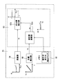
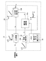
- FIG. 8 is a circuit configuration diagram of a thermal flow meter according to the second embodiment.
- FIG. 9 is a diagram for explaining a strain amount detection unit of the thermal type flow meter according to the second embodiment, and (a) is a diagram for explaining a circuit configuration of the strain amount detection unit. (b) is a figure for demonstrating the arrangement
- FIG. 10 is a diagram for explaining correction of the thermal type flow meter according to the second embodiment.
- the second embodiment aims to reduce the influence of a change in resistance value due to thermal stress on the resistor of the input circuit 62 as an analog circuit.
- the output value Va may deviate from the normal value due to temperature change (ie, strain amount ⁇ due to thermal stress). Therefore, in the present embodiment, the following configuration is adopted.
- the second embodiment differs from the first embodiment in that the distortion amount acting on the oscillator 64 is measured by the distortion amount detection unit 66 and the output value is corrected in the first embodiment.
- a distortion amount generated in the input circuit 62 is measured by the distortion amount detection unit 66A, and this output value is corrected. Since other configurations are the same as those of the first embodiment, detailed description thereof is omitted.
- the integrated circuit 23 includes an input circuit 62 as an analog circuit having a resistor, as in the first embodiment. At a position adjacent to the resistor of the input circuit 62, a strain amount detector 66A that detects the amount of strain generated in the resistor is disposed.
- the strain amount detector 66A measures the amount of strain acting on the resistor 62a of the input circuit 62, as shown in FIG. 9B.
- the strain amount detection unit 66A includes strain amount detection resistors 66g and 66h that detect the strain amount generated in the resistor 62a of the input circuit 62, and fixed resistors.
- a Wheatstone bridge circuit formed by the bodies 66i and 66j, to which a power supply 90 is connected.
- a diffusion resistance whose longitudinal direction is 45 degrees with the ⁇ 100> axis of the Si single crystal and perpendicular thereto. It is arranged so as to be a diffused resistor, and is configured in the strain amount detection unit 66A.
- the correction amount calculation unit 63a includes a polynomial or the like of the relationship between the potential V ⁇ (distortion amount ⁇ ) measured and stored in advance in the memory 65 and the correction amount dv (deviation of the output frequency of the oscillator corresponding to the change in distortion amount).
- a correction amount dv for the distortion amount is calculated using a correction formula or a correction map. Using the calculated correction amount dv, the output value Va output from the input circuit 62 is corrected by the output value correction unit 63b, and the corrected output value Va is used as the output value of the input circuit 62.
- the strain amount detection unit 66A that detects the strain amount generated in the resistor 62a is disposed at a position adjacent to the resistor 62a of the input circuit 62 that is an analog circuit, thereby detecting the strain amount. Since the output frequency, which is the output value of the oscillator 64, is corrected based on the amount of distortion detected from the unit 66A, the flow rate detection signal (output signal) from the flow rate detection element that directly affects the flow rate value is processed accurately. In addition to the effects described above in the first embodiment, the flow rate error of the fluid to be measured can be corrected with high accuracy. In particular, since the Wheatstone bridge circuit is used for the distortion amount detection unit 66A, the distortion amount of the resistor 62a of the input circuit 62 can be detected with high accuracy without being affected by the internal resistance.
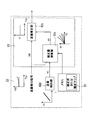
- FIG. 11 is a circuit configuration diagram of a thermal flow meter according to the third embodiment.
- FIG. 12 is a diagram for explaining a strain amount detection unit of a thermal type flow meter according to the third embodiment, and (a) is a diagram for explaining a circuit configuration of the strain amount detection unit. (b) is a figure for demonstrating the arrangement
- FIG. 13 is a diagram for explaining correction of the thermal flow meter according to the third embodiment.
- the output values of these analog circuits are corrected based on the amount of distortion acting on the resistor of the analog circuit such as the oscillator 64 or the input circuit 62, but in the third embodiment, Among the resistors, the amount of distortion of a resistor (that is, an integrated circuit) that easily causes variations in the flow rate value measured by thermal stress is detected, and the flow rate of the gas to be measured is measured based on the amount of distortion.
- the oscillator 64 has a position adjacent to the resistor 64 a.
- a strain amount detection unit 66B for detecting the strain amount generated in the resistor 64a is disposed. The configuration of the distortion amount detection unit 66B is the same.
- the strain amount detection unit 66B measures the amount of strain acting on the resistor 64a of the oscillator 64, and thermal stress has acted on the strain amount detection unit 66B.
- the potential V ⁇ changes as in the first embodiment. This change corresponds to the amount of strain ⁇ generated in the resistor 64a of the oscillator 64.
- the detected potential V ⁇ (distortion amount ⁇ ) is converted through an AD converter (not shown) and input to the correction amount calculation unit 63 a of the processing unit 63.
- the correction amount calculation unit 63 a calculates a flow rate correction amount based on the detected potential V ⁇ (distortion amount ⁇ ) and the flow rate detected by the flow rate detection element 24 via the input circuit 62.
- a correction formula or correction that is a polynomial or the like representing a deviation of the flow rate of the thermal flow meter 10 in accordance with the strain amount (thermal stress) from the potential V ⁇ (strain amount ⁇ ) and the flow rate in advance.
- a map is stored, and the correction amount calculation unit 63a calculates the flow amount correction amount for the distortion amount and the flow rate using these correction equations or correction maps.
- the flow rate value Vf0 obtained by digitizing the flow rate detection signal is corrected by the flow rate correction unit 63c, and the corrected flow rate is output as the flow rate value measured by the thermal flow meter 10.
- the flow rate value obtained by the flow rate detection signal (output signal) from the flow rate detection element that directly affects the flow rate value is corrected using the distortion amount generated in the resistor 64a of the oscillator 64. Therefore, it is possible to accurately correct the flow rate error of the fluid to be measured in consideration of the influence of other resistors including the oscillator 64.
- the strain amount detecting resistor 66b having the same material and shape as the resistor 64a of the oscillator 64 is used, the resistance caused by the thermal stress of the oscillator 64 is also used. An error in the flow rate of the measurement fluid can be accurately reflected in the flow rate value. Further, since the resistor 64a of the oscillator 64 and the strain amount detecting resistor 66b are arranged at the same distance D from the holding portion 33, the difference in expansion between the first resin 27 and the second resin 37 is caused. The strain amount of the resistor 64a due to thermal stress can be detected with high accuracy by the strain amount detecting resistor 66b.
- the flow rate detecting element and the integrated circuit are separated, but these may be integrated, and such a configuration is also included in the scope of the present invention.
- the circuit package is formed of the first resin (thermosetting resin) so as to cover the integrated circuit.
- the present invention is not limited to such a form.
- a circuit package circuit board in which an integrated circuit is not covered with a polymer resin and is bonded to a substrate through an adhesive may be used. Even in this case, the resistance of the integrated circuit is also distorted due to the thermal stress of the adhesive, and variations in measurement accuracy can be suppressed by the correction described in the first and second embodiments.
- the circuit package is formed integrally with the housing by the second resin (thermoplastic resin) so as to fix the circuit package, but the circuit package (including the circuit board described above) is formed in the housing (casing).
- the fixing method is not limited as long as it can be fixed to ().
- the circuit package may be fixed to the housing with an adhesive, or the circuit package may be fixed so as to be sandwiched between two members.
- the housing (casing) is thermally contracted to cause the housing to be twisted, thereby generating distortion in the integrated circuit.
Landscapes
- Physics & Mathematics (AREA)
- Fluid Mechanics (AREA)
- General Physics & Mathematics (AREA)
- Measuring Volume Flow (AREA)
Abstract
被計測気体の流量を演算する集積回路に熱応力が起因した歪が発生した場合であっても、計測精度のバラつきを抑えることができる熱式流量計を提供するために、熱式流量計は、流量検出素子24と、流量検出素子24からの出力信号に基づいて被計測気体の流量を演算する集積回路23と、が搭載された回路パッケージ20を備えている。回路パッケージ20を収納するとともに前記副通路が形成されたケーシング30と、を備えている。集積回路23は、抵抗体64aを有した発振器64を備えている。発振器64の抵抗体64aに隣接した位置には、抵抗体64aに発生する歪量を検出する歪量検出部66が配置されている。集積回路23は、歪量検出部23からの検出された歪量に基づいて、発振器64の出力値を補正する出力値補正部63bをさらに備える。
Description
本発明は熱式流量計に関する。
空気の流量を計測する熱式流量計は、空気流量を計測するための流量検出素子を備え、前記流量検出素子と計測対象である前記気体との間で熱伝達を行うことにより、気体の空気流量を計測するように構成されている。熱式流量計が計測する空気流量は色々な装置の重要な制御パラメータとして広く使用されている。熱式流量計の特徴は、他の方式の流量計に比べ相対的に高い精度で空気の流量を計測できることである。
しかし更なる空気流量の計測精度の向上が望まれている。例えば、内燃機関を搭載した車両では、省燃費の要望や排気ガス浄化の要望が非常に高い。これら要望に応えるには、内燃機関の主要パラメータである吸入空気量を高い精度で計測することが求められている。内燃機関に導かれる吸入空気量を計測する熱式流量計は、吸入空気量の一部を取り込む副通路と副通路に配置された流量検出素子とを備え、流量検出素子が被計測気体との間で熱伝達を行うことにより、副通路を流れる被計測気体の状態を計測して、内燃機関に導かれる吸入空気量を表す電気信号を出力する。
このような技術として、たとえば、特許文献1には「基板と、基板に形成されたダイアフラムと、ダイアフラム上に形成された発熱抵抗体および温度検出抵抗体とを有し、前記発熱抵抗体を加熱することによって被測定流体の流量を検出する熱式流量センサにおいて、ダイアフラム上の発熱抵抗体に対して被測定流体の流れの上流側および下流側に歪検出抵抗体が形成されており、歪検出抵抗体によってダイアフラム上に発生する歪量を検出し、前記検出された歪量に基づいて発熱抵抗体と温度検出抵抗体が検出する流量信号の歪補償を行う」技術が開示されている。
しかしながら、特許文献1の如く流量検出素子のダイアフラム上に発生する歪量を検出した場合であっても、流量検出素子からの出力信号に基づいて被計測気体の流量を演算する集積回路(たとえばLSI)には、熱式流量計に作用する熱応力(たとえば、基板を収容するケーシングや集積回路を基板に固定する接着剤や樹脂などに発生する熱応力)の影響により歪が発生することがある。この結果、センサアセンブリ内に配置されるLSIの出力(主に抵抗が歪により変化)が変動し、熱式流量計の測定精度が低下するおそれがある。
本発明はこのような点を鑑みてなされたものであり、その目的とするところは、被計測気体の流量を演算する集積回路に、熱応力を起因とした歪が発生した場合であっても、計測精度のバラつきを抑えることができる熱式流量計を提供することにある。
上記目的を達成すべく、本発明に係る熱式流量計は、主通路から取り込まれた被計測気体を流すための副通路と、副通路を流れる被計測気体との間で熱伝達を行うことにより被計測気体の流量を計測するための流量検出素子とを備える。熱式流量計は、流量検出素子と、流量検出素子からの出力信号に基づいて被計測気体の流量を演算する集積回路と、が搭載された回路パッケージと、回路パッケージを収納するとともに副通路が形成されたケーシングと、を備える。集積回路は抵抗体を有したアナログ回路を備えており、アナログ回路の前記抵抗体に隣接した位置において、抵抗体に発生する歪量を検出し、該歪量に基づいてアナログ回路の出力値または被計測気体の流量値を補正する。
本発明によれば、被計測気体の流量を演算する集積回路に、熱応力を起因とした歪が発生した場合であっても、計測精度のバラつきを抑えることができる。
以下、本発明のいくつかの実施の形態を図を参照して説明する。
〔第1実施形態〕
図1は、電子燃料噴射方式の内燃機関制御システムに、本発明に係る熱式流量計として、熱式流量計を使用した一実施形態を示すシステム図である。図1に示すように、エンジンシリンダ112とエンジンピストン114を備える内燃機関110の動作に基づき、吸入空気が被計測気体IAとしてエアクリーナ122から吸入される。吸入された被計測気体IAは、主通路70が形成された吸気管71を含む例えば吸気ボディ、スロットルボディ126、吸気マニホールド128を介してエンジンシリンダ112の燃焼室に導かれる。
〔第1実施形態〕
図1は、電子燃料噴射方式の内燃機関制御システムに、本発明に係る熱式流量計として、熱式流量計を使用した一実施形態を示すシステム図である。図1に示すように、エンジンシリンダ112とエンジンピストン114を備える内燃機関110の動作に基づき、吸入空気が被計測気体IAとしてエアクリーナ122から吸入される。吸入された被計測気体IAは、主通路70が形成された吸気管71を含む例えば吸気ボディ、スロットルボディ126、吸気マニホールド128を介してエンジンシリンダ112の燃焼室に導かれる。
燃焼室に導かれる吸入空気である被計測気体IAの流量は、本実施形態に係る熱式流量計10で計測され、計測された流量に基づいて燃料噴射弁152より燃料が供給され、吸入空気である被計測気体IAと共に混合気の状態で燃焼室に導かれる。なお、本実施形態では、燃料噴射弁152は内燃機関の吸気ポートに設けられ、吸気ポートに噴射された燃料が吸入空気である被計測気体IAと共に混合気を成形し、吸気弁116を介して燃焼室に導かれ、燃焼して機械エネルギを発生する。
熱式流量計10は、図1に示す内燃機関の吸気ポートに燃料を噴射する方式だけでなく、各燃焼室に燃料を直接噴射する方式にも同様に使用できる。両方式とも熱式流量計10の使用方法を含めた制御パラメータの計測方法および燃料供給量や点火時期を含めた内燃機関の制御方法の基本概念は略同じであり、両方式の代表例として吸気ポートに燃料を噴射する方式を図1に示す。
燃焼室に導かれた燃料および空気は、燃料と空気の混合状態を成しており、点火プラグ154の火花着火により、爆発的に燃焼し、機械エネルギを発生する。燃焼後の気体は排気弁118から排気管に導かれ、排気EAとして排気管から車外に排出される。燃焼室に導かれる吸入空気である被計測気体IAの流量は、アクセルペダルの操作に基づいてその開度が変化するスロットルバルブ132により制御される。燃焼室に導かれる吸入空気の流量に基づいて燃料供給量が制御され、運転者はスロットルバルブ132の開度を制御して燃焼室に導かれる吸入空気の流量を制御することにより、内燃機関が発生する機械エネルギを制御することができる。
エアクリーナ122から取り込まれ主通路70を流れる吸入空気である被計測気体IAの流量、湿度および温度が、熱式流量計10により計測され、熱式流量計10から吸入空気の流量、湿度および温度を表す電気信号が制御装置200に入力される。また、スロットルバルブ132の開度を計測するスロットル角度センサ144の出力が制御装置200に入力され、さらに内燃機関のエンジンピストン114や吸気弁116や排気弁118の位置や状態、さらに内燃機関の回転速度を計測するために、回転角度センサ146の出力が、制御装置200に入力される。排気EAの状態から燃料量と空気量との混合比の状態を計測するために、酸素センサ148の出力が制御装置200に入力される。
制御装置200は、熱式流量計10の出力である吸入空気の流量、湿度、および温度、および回転角度センサ146からの内燃機関の回転速度、に基づいて燃料噴射量や点火時期を演算する。これら演算結果に基づいて、燃料噴射弁152から供給される燃料量、また点火プラグ154により点火される点火時期が制御される。燃料供給量や点火時期は、実際にはさらに熱式流量計10で計測される吸気温度やスロットル角度の変化状態、エンジン回転速度の変化状態、酸素センサ148で計測された空燃比の状態に基づいて制御されている。制御装置200はさらに内燃機関のアイドル運転状態において、スロットルバルブ132をバイパスする空気量をアイドルエアコントロールバルブ156により制御し、アイドル運転状態での内燃機関の回転速度を制御する。
内燃機関の主要な制御量である燃料供給量や点火時期はいずれも熱式流量計10の出力を主パラメータとして演算される。従って熱式流量計10の計測精度の向上や経時変化の抑制、信頼性の向上が、車両の制御精度の向上や信頼性の確保に関して重要である。特に近年、車両の省燃費に関する要望が非常に高く、また排気ガス浄化に関する要望が非常に高い。これらの要望に応えるには熱式流量計10により計測される吸入空気である被計測気体IAの流量の計測精度の向上が極めて重要である。
図2は、本実施形態に係る熱式流量計10を構成する回路パッケージの平面図である。図2に示すように、本実施形態に係る熱式流量計10を構成する回路パッケージ20には、流量検出素子24と演算部である集積回路(LSI)23とが搭載されている。回路パッケージ20は、金属製のリードフレーム21に上述した集積回路(LSI)23、流量検出素子24が、接着シート26を介して接着されている。集積回路23と流量検出素子24との間、集積回路23とリードフレーム21との間は、金線28、29によってワイヤボンデングにより結線することで電気的に接続される。その後、これらを熱硬化性樹脂である第1樹脂27(高分子樹脂)によりモールドし、回路パッケージ20に成形する。これにより、集積回路23が第1樹脂27で覆われる。
なお、集積回路23は、センサチップである流量検出素子24を制御するとともに、流量検出素子24からのアナログ信号をデジタル信号に変換して、被計測気体IAの流量を演算し、外部に出力するように構成されている。流量検出素子24および集積回路23の詳細は、図5を用いて後述する。
図3は、本実施形態に係る熱式流量計の平面図であり、図4は、図3のA-A線矢視断面図である。なお、図3は、熱式流量計10の前面カバー41と背面カバー42とを取り外した状態を示した図である。
本実施形態に係る熱式流量計10は、図3および図4に示すように、上述した回路パッケージ20と、回路パッケージ20を固定して収容するハウジング31と、ハウジング31の前面および背面に取り付けられる前面カバー41および背面カバー42と、を備えている(図4参照)。図2に示す回路パッケージ20は、ケーシング30に収納される。本実施形態では、ハウジング31の前面および背面に、前面カバー41および背面カバー42を取り付けることにより、回路パッケージ20を固定して収容するケーシング30が形成される。
ここで、ハウジング31は、主通路70を流れる被計測気体を流量検出素子24に導くための副通路溝32が形成されている。副通路溝32は、ハウジング31の前面および背面に形成されており、ハウジング31の前面側に前面カバー41を覆い、その背面側に背面カバー42を覆うことにより、流量検出素子24に主通路70から取り込まれた被計測気体を流すための副通路43が形成される。
副通路43は、主通路70の上流側に面したケーシング30の側面に入口43aが形成され、その下流側に面したケーシング30の側面に出口43bが形成さている。副通路43の入口43aから取り込まれた被計測気体は、背面側に形成された背面側副通路43cを通過する。背面側副通路43cを通過した被計測気体IAは、前面および背面が貫通した貫通部43dに配置された流量検出素子24を通過し、貫通部43dを通過した被計測気体は、前面側に形成された前面側副通路43eを通過し、出口43bから流出する。
ここで、ハウジング31は、回路パッケージ20を金型内に配置した状態で、熱可塑性樹脂(第2樹脂)37で一体的に成形される。これにより、回路パッケージ20を保持(固定)する保持部33が、副通路溝32の一部に形成される。ここで、保持部33は、回路パッケージ20を周回するように、回路パッケージ20を保持し、流量検出素子24は副通路溝32(貫通部43d)中に配置される。このような結果、ケーシング30の保持部33は、流量検出素子24と集積回路(LSI)23との間または集積回路23上において回路パッケージ20を保持するとともに、副通路43に対して精度良く流量検出素子23を配置することができる。
図5は、第1実施形態に係る熱式流量計の回路構成図である。図6は、第1実施形態に係る熱式流量計の歪量検出部を説明するための図であり、(a)は、歪量検出部の回路構成を説明するための図であり、(b)は、歪量検出部の定電流回路を説明するための図であり、(c)は、歪量検出部を構成する抵抗の配置状態を説明するための図である。図7は、第1実施形態に係る熱式流量計の補正を説明するための図である。
ここで、流量検出素子24は、一般的な熱式流量の測定を行うものであり、副通路43を流れる被計測気体IAとの間で熱伝達を行うことにより、被計測気体IAの流量を計測する。具体的には、流量検出素子24は、温度検出素子としてシリコンやセラミック等の熱伝導率の良い材料で構成される平板基板にダイアフラム24aを形成し、ダイアフラム24aには、図5に示すように、ヒータブリッジ回路51と温度検出ブリッジ回路52とが配置されている。
集積回路23は、流量検出素子24を制御し、流量検出素子24からの出力信号に基づいて被計測気体の流量を演算し、これを出力するものである。集積回路23には、ヒーター制御部61が備えられており、電源からトランジスタ61bを介してヒータブリッジ回路51のヒーター抵抗体51aに電流を流すことでヒーター抵抗体51aを加熱制御する。流量検出素子24は、このヒーター抵抗体51aにより発熱した流体の熱量に基づいて被計測気体の流量を測定している。集積回路23では、流量検出素子24の出力信号に対して流量に応じた出力信号に信号処理を行う。
より具体的には、図5に示すように、ヒータブリッジ回路51は、ヒーター温度検出抵抗体51bと、測温抵抗体51cと、固定抵抗51d,51fとによって形成されたブリッジ回路であり、電源90が接続されている。ヒーター温度検出抵抗体51bと固定抵抗51fとの接続点の電位と、測温抵抗体51cと固定抵抗51dの接続点の電位とが、オペアンプ61aの入力端子に接続され、これらの電位が同一になるようにオペアンプ61aによりヒーター抵抗体51aへ供給される加熱電流がフィードバック制御される。
温度検出ブリッジ回路52は、ヒーター抵抗体51aに対して空気流れの方向の上流側に配置され、ヒーター抵抗体51aからの熱影響によって抵抗値が変化する感温抵抗体52a,52bと、ヒーター抵抗体51aに対して空気流れの方向の下流側に配置されている感温抵抗体52c,52dによって形成されたブリッジ回路である。温度検出ブリッジ回路52は、電源90にも接続されている。
空気流量に応じた差動信号は、感温抵抗体52aと52dの接続点と、感温抵抗体52cと52bの接続点の電位差であり、この差動信号はAD変換器である入力回路62に入力される。入力回路62の出力は、処理部(CPU)63に入力される。処理部63では、発振器64により出力された所定の周波数が入力される。さらに、処理部63では、ROM、RAM等のメモリ65に格納された調整情報を使用し、調整された流量信号は、DA変換器または周波数出力変換回路(FRC)などからなる出力回路67に入力され、電圧信号あるいは周波数信号に変換される。最終的にメモリ65に格納された情報に基づき切替スイッチであるマルチプレクサ(図示せず)によって電圧信号あるいは周波数信号が流量出力として出力される。
ここで、図3および図4に戻り、回路パッケージ20は、第1樹脂27により、LSIである集積回路23を少なくとも覆うので、集積回路(LSI)32を構成するシリコン素子と第1樹脂27との間に熱膨張係数の差により、集積回路23に熱応力が発生する。特に、本実施形態に係る構造では、回路パッケージ20は第1樹脂27により形成され、ハウジング11は第2樹脂37により形成されるため、回路パッケージ20を保持し固定する保持部33と回路パッケージ20との界面(集積回路23近傍)に、第1樹脂27と第2樹脂37の線膨張係数差に起因する熱応力がさらに発生する。これにより、集積回路23のアナログ回路の抵抗体の抵抗値が変化し、この変化により演算される被計測気体の流量に誤差が生じることがある。このような点を鑑みて、本実施形態では、以下の如き構成をさらに設けている。
第1実施形態では、アナログ回路として発振器64の抵抗体の、熱応力による抵抗値の変化の影響を低減することを目的としている。RC発振器など発振器64の抵抗体64aは、ブリッジ回路からなる抵抗体を構成していないので、上述した熱応力により、その抵抗体の抵抗値の変化が、発振器64の出力周波数に影響を受けやすい。たとえば図7の発振器64に示す温度T(ε)と周波数f0の関係のごとく、温度変化(すなわち熱応力による歪量ε)により、周波数f0は変化してしまう。そこで、本実施形態では、以下の如き構成を採用している。
図5、図6(a)および(c)に示すように、具体的には、集積回路23のアナログ回路である発振器64の抵抗体64aに隣接した位置に、抵抗体64aに発生する歪量を測定する歪量検出部66が配置されている。歪量検出部66は、定電流回路66aを介して電流が供給されており、定電流回路66aは、熱応力の作用に拘らず一定の電流を歪量検出用抵抗体66bに供給することができる。
定電流回路66aは、図6(b)に示すように、基準電圧Vrefが非反転入力端子に印加されるオペアンプ601と、オペアンプ601の出力がゲート端子へ印加されるNMOSトランジスタ602と、NMOSトランジスタ602のソース端子と接地点との間に外部端子603を介して接続された外付け抵抗604と、NMOSトランジスタ604のドレイン端子に接続されたカレントミラー回路605とを備えている。また、NMOSトランジスタ602のソース端子がオペアンプ601の反転入力端子に接続されている。
カレントミラー回路605は、ドレイン端子およびゲート端子がNMOSトランジスタ602のドレイン端子に接続されたPMOSトランジスタ607と、ゲート端子がNMOSトランジスタ602のドレイン端子に接続されたPMOSトランジスタ608とを有している。カレントミラー回路605は、PMOSトランジスタ608のドレイン端子から、基準電流Isに対する電流比がミラー比となる定電流の出力電流Ioutを出力する。ミラー比は、PMOSトランジスタ607、608の素子サイズの比で決まる。
本実施形態では、定電流回路66aの外付け抵抗604が、熱応力による影響を受け難くするため、本実施形態では、拡散抵抗である外付け抵抗604は、その長手方向がSi単結晶の<100>軸と平行である拡散抵抗604aと、これと垂直である拡散抵抗604bとを直列に接続した構造となっている。これにより、定電流回路66aの内部において、熱応力により出力電流Ioutが変動し難くなる。
定電流回路66aの出力電流Iout側に、発振器64の抵抗体64aと同じ材料および同じ形状となる歪量検出用抵抗体66bが配置されている。さらに、発振器64の抵抗体64aと歪量検出用抵抗体66bとは、保持部33から同じ距離Dとなる位置に配置されている。
歪量検出用抵抗体66bには、定電流回路66aから定電流が流れているので、歪量検出用抵抗体66bに熱応力が作用したときに、歪量検出用抵抗体66bの抵抗値が変化することより、図に示す位置における電位Vεが変化する。この変化が発振器64の抵抗体64aに発生する歪量εに相当する。
次に、歪量検出用抵抗体66bで検出された電位Vε(歪量ε)が、AD変換器(図示せず)を介してデジタル値に変換され、処理部63の補正量演算部63aに入力される。補正量演算部63aでは、メモリ65で予め測定して記憶された電位Vε(歪量ε)と補正量dvの関係(歪量の変化に対応した発振器の出力周波数のずれ)の多項式等ならなる補正式または補正マップを用いて、歪量に対する補正量dvを演算する。演算された補正量dvを用いて、発振器64から出力される周波数f0を出力値補正部63bで補正し、補正した周波数fを発振器64の出力値として用いる。
このように、本実施形態では、アナログ回路であるの発振器64の抵抗体64aに隣接した位置に、抵抗体64aに発生する歪量を検出する歪量検出部66を配置し、歪量検出部66からの検出された歪量に基づいて、発振器64の出力値である出力周波数を補正する。これにより、発振器(アナログ回路)64に起因した被計測流体の流量の誤差を精度良く補正することができる。すなわち、第1樹脂27と集積回路23との熱膨張差により作用する発振器への熱応力、さらには、保持部33において発生する第1樹脂27と第2樹脂37との間に発生する熱応力が起因した発振器64の出力周波数のずれ(正規の値からのずれ)を抑えることができる。このような結果、集積回路23のアナログ回路のうち、熱応力により測定した流量精度におおきな影響を与える発振器64の出力値を補正することができる。
また本実施形態では、発振器64の抵抗体64aと同じ材料および同じ形状となる歪量検出用抵抗体66bを用いているので、歪量検出用抵抗体66bと抵抗体64aとの変形はほぼ同程度となる。これにより、歪量検出用抵抗体66bで、より精度よく抵抗体64aの歪量εを測定することができる。このような結果、発振器64の熱応力に起因した被計測流体の流量の誤差を精度良く補正することができる。
特に、発振器64の抵抗体64aと歪量検出用抵抗体66bとを、保持部33から同じ距離Dとなる位置に配置したので、第1樹脂27と第2樹脂37との膨張差が起因した熱応力による抵抗体64aの歪量を、歪量検出用抵抗体66bで精度良く検出することができる。
〔第2実施形態〕
図8は、第2実施形態に係る熱式流量計の回路構成図である。図9は、第2実施形態に係る熱式流量計の歪量検出部を説明するための図であり、(a)は、歪量検出部の回路構成を説明するための図であり、(b)は、歪量検出部を構成する抵抗の配置状態を説明するための図である。図10は、第2実施形態に係る熱式流量計の補正を説明するための図である。
図8は、第2実施形態に係る熱式流量計の回路構成図である。図9は、第2実施形態に係る熱式流量計の歪量検出部を説明するための図であり、(a)は、歪量検出部の回路構成を説明するための図であり、(b)は、歪量検出部を構成する抵抗の配置状態を説明するための図である。図10は、第2実施形態に係る熱式流量計の補正を説明するための図である。
上述したようなAD変換器などの入力回路62は、流量検出素子24からの流量に関する信号が入力されるので、入力回路62の抵抗体の抵抗値の変化が、そのまま流量のばらつきに影響を与えてしまう。そこで、第2実施形態では、アナログ回路として入力回路62の抵抗体の、熱応力による抵抗値の変化の影響を低減することを目的としている。
たとえば図10の入力回路62に示す入力値Vinと出力値Vaの関係のごとく、温度変化(すなわち熱応力による歪量ε)により、正規の値から出力値Vaがずれてしまうことがある。そこで、本実施形態では、以下の如き構成を採用している。
なお、第2実施形態が第1実施形態と相違する点は、第1実施形態では歪量検出部66で発振器64に作用する歪量を測定し、この出力値を補正したが、第2実施形態では歪量検出部66Aで入力回路62に発生する歪量を測定し、この出力値を補正する点である。その他の構成は、第1実施形態と同じであるので、その詳細な説明は省略する。
図8に示すように、本実施形態に係る集積回路23は、第1実施形態に係るものと同様に、抵抗体を有したアナログ回路として入力回路62を備えている。入力回路62の抵抗体に隣接した位置には、抵抗体に発生する歪量を検出する歪量検出部66Aが配置されている。
歪量検出部66Aは、図9(b)に示すように、入力回路62の抵抗体62aに作用する歪量を測定するものである。具体的には、図9(a)に示すように、歪量検出部66Aは、入力回路62の抵抗体62aに発生する歪量を検出する歪量検出用抵抗体66g,66hと、固定抵抗体66i,66jによって形成されたホイーストンブリッジ回路であり、電源90が接続されている。本実施形態では、図示のごとく、各隣接する抵抗体を、熱応力による影響を受け難くするため、その長手方向がSi単結晶の<100>軸と45度である拡散抵抗と、これと垂直である拡散抵抗となるように配置し、歪量検出部66Aに構成されている。
このような結果、歪量検出部66Aに熱応力が作用したときに、歪量検出用抵抗体66g,66hの抵抗値が変化することより、図に示す位置における電位Vεが変化する。この変化が発振器64の抵抗体64aに発生する歪量εに相当する。
次に、検出された電位Vε(歪量ε)が、AD変換器(図示せず)を介してデジタル値に変換され、処理部63の補正量演算部63aに入力される。補正量演算部63aでは、メモリ65で予め測定して記憶された電位Vε(歪量ε)と補正量dvの関係(歪量の変化に対応した発振器の出力周波数のずれ)の多項式等からなる補正式または補正マップを用いて、歪量に対する補正量dvを演算する。演算された補正量dvを用いて、入力回路62から出力される出力値Vaを出力値補正部63bで補正し、補正した出力値Vaを入力回路62の出力値として用いる。
このように、本実施形態では、アナログ回路であるの入力回路62の抵抗体62aに隣接した位置に、抵抗体62aに発生する歪量を検出する歪量検出部66Aを配置し、歪量検出部66Aからの検出された歪量に基づいて、発振器64の出力値である出力周波数を補正するので、流量値に直接影響する流量検出素子からの流量検出信号(出力信号)を精度よく、処理部63に取り込むことができ、第1実施形態における上述した作用効果に加えて、さらに、被計測流体の流量の誤差を精度良く補正することができる。とくに、歪量検出部66Aに、ホイーストンブリッジ回路を用いたので、内部抵抗の影響を受けることがなく、精度良く入力回路62の抵抗体62aの歪量を検出することができる。
〔第3実施形態〕
図11は、第3実施形態に係る熱式流量計の回路構成図である。図12は、第3実施形態に係る熱式流量計の歪量検出部を説明するための図であり、(a)は、歪量検出部の回路構成を説明するための図であり、(b)は、歪量検出部を構成する抵抗の配置状態を説明するための図である。図13は、第3実施形態に係る熱式流量計の補正を説明するための図である。
図11は、第3実施形態に係る熱式流量計の回路構成図である。図12は、第3実施形態に係る熱式流量計の歪量検出部を説明するための図であり、(a)は、歪量検出部の回路構成を説明するための図であり、(b)は、歪量検出部を構成する抵抗の配置状態を説明するための図である。図13は、第3実施形態に係る熱式流量計の補正を説明するための図である。
第1および第2実施形態では、発振器64または入力回路62などのアナログ回路の抵抗体に作用する歪量に基づいてこれらアナログ回路の出力値を補正したが、第3実施形態では、アナログ回路の抵抗体のうち、熱応力により測定した流量の値にバラつきを生じさせやすい抵抗体(すなわち、集積回路)の歪量を検出し、この歪量に基づいて被計測気体の流量を測定する。本実施形態では、その一例として、アナログ回路のうち、第1実施形態と同様に、図11、12(a),(b)に示すように、発振器64の抵抗体64aに隣接した位置には、抵抗体64aに発生する歪量を検出する歪量検出部66Bを配置する。
歪量検出部66Bの構成は同じである。
歪量検出部66Bの構成は同じである。
歪量検出部66Bは、図12(a)、(b)に示すように、発振器64の抵抗体64aに作用する歪量を測定するものであり、歪量検出部66Bに熱応力が作用したときに、第1実施形態と同様に電位Vεが変化する。この変化が発振器64の抵抗体64aに発生する歪量εに相当する。
次に、図13に示すように、検出された電位Vε(歪量ε)が、AD変換器(図示せず)を介して変換され、処理部63の補正量演算部63aに入力される。補正量演算部63aでは、検出された電位Vε(歪量ε)と、入力回路62を介して流量検出素子24で検出された流量とに基づいて、流量補正量を演算する。
たとえば、メモリ65には、予め、電位Vε(歪量ε)と流量とから、歪量(熱応力)に応じた熱式流量計10の流量のずれを表した多項式等ならなる補正式または補正マップが記憶されており、補正量演算部63aでは、これらの補正式または補正マップを用いて歪量および流量に対する流量補正量を演算する。演算された補正量dvを用いて、流量検出信号をデジタル化した流量値Vf0を流量補正部63cで補正し、補正した流量を熱式流量計10が測定した流量値として出力する。
このように、本実施形態では、流量値に直接影響する流量検出素子からの流量検出信号(出力信号)でえられた流量値を、発振器64の抵抗体64aに発生する歪量を用いて補正することができるので、発振器64を含む他の抵抗体の影響も加味して、被計測流体の流量の誤差を精度良く補正することができる。
また、第1実施形態と同様に本実施形態でも、発振器64の抵抗体64aと同じ材料および同じ形状となる歪量検出用抵抗体66bを用いているので、発振器64の熱応力に起因した被計測流体の流量の誤差を精度良く、流量値に反映することができる。また、発振器64の抵抗体64aと歪量検出用抵抗体66bとを、保持部33から同じ距離Dとなる位置に配置したので、第1樹脂27と第2樹脂37との膨張差が起因した熱応力による抵抗体64aの歪量を、歪量検出用抵抗体66bで精度良く検出することができる。
以上、本発明の実施形態について詳述したが、本発明は、前記の実施形態に限定されるものではなく、特許請求の範囲に記載された本発明の精神を逸脱しない範囲で、種々の設計変更を行うことができるものである。
本実施形態では、流量検出素子と集積回路が別体となっていたが、これらが一体となっていてもよく、このような構成のものも本発明の範囲に含まれる。
また、本実施形態では、回路パッケージは、集積回路を覆うように第1樹脂(熱硬化性樹脂)により成形されていたが、このような形態に限定されるものではない。たとえば、集積回路が高分子樹脂で覆われずに接着剤を介して基板に接着された回路パッケージ(回路基板)であってもよい。この場合であっても、接着剤の熱応力により集積回路の抵抗にも歪が生じ、上述した第1および第2の実施形態で示した補正により、計測精度のバラつきを抑えることができる。
また、本実施形態では、回路パッケージを固定するように、回路パッケージをハウジングに一体的に第2樹脂(熱可塑性樹脂)で成形したが、回路パッケージ(上述した回路基板を含む)をハウジング(ケーシング)に固定することができるのであれば、その固定方法は限定されるものではない。たとえば、回路パッケージをハウジングに接着剤に固定してもよく、回路パッケージを2つの部材で挟持ように固定してもよい。
このような場合であっても、ハウジング(ケーシング)の熱収縮により、ハウジングにねじれが生じ、これにより集積回路に歪が発生し、上述した第1および第2の実施形態で示した補正により、計測精度のバラつきを抑えることができる。
10:熱式流量計、11:ハウジング、20:パッケージ、21:リードフレーム、23:集積回路、24:流量検出素子、24a:ダイアフラム、26:接着シート、27:第1樹脂、28:金線、29:金線、30:ケーシング、31:ハウジング、32:副通路溝、33:保持部、37:第2樹脂、41:前面カバー、42:背面カバー、43:副通路、43a:入口、43b:出口、43c:背面側副通路、43d:貫通部、43e:前面側副通路、51:ヒータブリッジ回路、51a:ヒーター抵抗体、51b:温度検出抵抗体、51c:測温抵抗体、51d:固定抵抗、51f:固定抵抗、52:温度検出ブリッジ回路、52a:感温抵抗体、52c:感温抵抗体、61:ヒーター制御部、61a:オペアンプ、61b:トランジスタ、62:入力回路、62a:抵抗体、63:処理部、63a:補正量演算部、63b:出力値補正部、64:発振器、64a:抵抗体、65:メモリ、66、66A、66B:歪量検出部、66a:定電流回路、66b,66g,66h:歪量検出用抵抗体、66i:固定抵抗体、67:出力回路、70:主通路、71:吸気管、90:電源、EA:排気、IA:被計測気体
Claims (11)
- 主通路から取り込まれた被計測気体を流すための副通路と、該副通路を流れる被計測気体との間で熱伝達を行うことにより前記被計測気体の流量を計測するための流量検出素子とを備える熱式流量計であって、
該熱式流量計は、
前記流量検出素子と、該流量検出素子からの出力信号に基づいて前記被計測気体の流量を演算する集積回路と、が搭載された回路パッケージと、
該回路パッケージを収納するとともに前記副通路が形成されたケーシングと、を備えており、
前記集積回路は、抵抗体を有したアナログ回路を備えており、
該アナログ回路の前記抵抗体に隣接した位置には、該抵抗体に発生する歪量を検出する歪量検出部が配置されており、
前記集積回路は、該歪量検出部からの検出された歪量に基づいて、前記アナログ回路の出力値を補正する出力値補正部をさらに備えることを特徴とする熱式流量計。 - 前記歪量検出部は、前記抵抗体と同じ材料および同じ形状となっていることを特徴とする請求項1に記載の熱式流量計。
- 前記アナログ回路は発振器であり、前記出力値補正部は、前記出力値として前記発振器の出力周波数を補正することを特徴とする請求項1に記載の熱式流量計。
- 前記歪量検出部は、ホイーストンブリッジ回路からなることを特徴とする請求項1に記載の熱式流量計。
- 前記ケーシングには、前記流量検出素子と前記集積回路との間または前記集積回路上において前記回路パッケージを保持する保持部が形成されていることを特徴とする請求項1に記載の熱式流量計。
- 前記抵抗体と前記歪量検出部とは、前記保持部から同じ距離となる位置に配置されていることを特徴とする請求項5に記載の熱式流量計。
- 主通路から取り込まれた被計測気体を流すための副通路と、該副通路を流れる被計測気体との間で熱伝達を行うことにより、前記被計測気体の流量を計測するための流量検出素子を備える熱式流量計であって、
該熱式流量計は、
前記流量検出素子と、該流量検出素子からの出力信号に基づいて前記被計測気体の流量を演算する集積回路と、が搭載された回路パッケージと、
該回路パッケージを収納するとともに、前記副通路が形成されたケーシングと、を備えており、
前記集積回路は、抵抗体を有したアナログ回路を備えており、
該アナログ回路の前記抵抗体に隣接した位置には、該抵抗体に発生する歪量を検出する歪量検出部が配置されており、
前記集積回路は、該歪量検出部から検出された歪量に基づいて、前記被計測気体の流量値を補正する流量補正部を備えていることを特徴とする熱式流量計。 - 前記歪量検出部は、前記抵抗体と同じ材料および同じ形状となっていることを特徴とする請求項7に記載の熱式流量計。
- 前記アナログ回路は発振器であることを特徴とする請求項7に記載の熱式流量計。
- 前記ケーシングには、前記流量検出素子と前記集積回路との間または前記集積回路上において前記回路パッケージを保持する保持部が形成されていることを特徴とする請求項7に記載の熱式流量計。
- 前記抵抗体と前記歪量検出部とは、前記保持部から同じ距離となる位置に配置されていることを特徴とする請求項10に記載の熱式流量計。
Applications Claiming Priority (2)
| Application Number | Priority Date | Filing Date | Title |
|---|---|---|---|
| JP2013160820A JP5968279B2 (ja) | 2013-08-01 | 2013-08-01 | 熱式流量計 |
| JP2013-160820 | 2013-08-01 |
Publications (1)
| Publication Number | Publication Date |
|---|---|
| WO2015015819A1 true WO2015015819A1 (ja) | 2015-02-05 |
Family
ID=52431372
Family Applications (1)
| Application Number | Title | Priority Date | Filing Date |
|---|---|---|---|
| PCT/JP2014/052602 Ceased WO2015015819A1 (ja) | 2013-08-01 | 2014-02-05 | 熱式流量計 |
Country Status (2)
| Country | Link |
|---|---|
| JP (1) | JP5968279B2 (ja) |
| WO (1) | WO2015015819A1 (ja) |
Citations (1)
| Publication number | Priority date | Publication date | Assignee | Title |
|---|---|---|---|---|
| JP2011215062A (ja) * | 2010-04-01 | 2011-10-27 | Hitachi Automotive Systems Ltd | 熱式流量センサ |
Family Cites Families (1)
| Publication number | Priority date | Publication date | Assignee | Title |
|---|---|---|---|---|
| JP3366818B2 (ja) * | 1997-01-16 | 2003-01-14 | 株式会社日立製作所 | 熱式空気流量計 |
-
2013
- 2013-08-01 JP JP2013160820A patent/JP5968279B2/ja active Active
-
2014
- 2014-02-05 WO PCT/JP2014/052602 patent/WO2015015819A1/ja not_active Ceased
Patent Citations (1)
| Publication number | Priority date | Publication date | Assignee | Title |
|---|---|---|---|---|
| JP2011215062A (ja) * | 2010-04-01 | 2011-10-27 | Hitachi Automotive Systems Ltd | 熱式流量センサ |
Also Published As
| Publication number | Publication date |
|---|---|
| JP5968279B2 (ja) | 2016-08-10 |
| JP2015031580A (ja) | 2015-02-16 |
Similar Documents
| Publication | Publication Date | Title |
|---|---|---|
| CN104081169B (zh) | 流量计测装置 | |
| JP6352423B2 (ja) | 物理量検出装置 | |
| CN106662476B (zh) | 物理量检测装置 | |
| US9851234B2 (en) | Physical quantity measuring device | |
| WO2016092984A1 (ja) | 物理量検出装置 | |
| JP2016197105A (ja) | 温度、絶対圧および差圧が組み合わされたセンサアセンブリ | |
| JP2005009965A (ja) | 熱式空気流量計 | |
| JP6568593B2 (ja) | 物理量検出装置 | |
| WO2005050143A1 (ja) | 熱式流体流量計 | |
| JP5152292B2 (ja) | 流量計測装置 | |
| JP6181900B2 (ja) | 空気流量検出装置 | |
| CN102822641B (zh) | 热式流量传感器 | |
| CN108458762B (zh) | 热式空气流量计 | |
| WO2013187170A1 (ja) | 熱式流量計 | |
| JP6932640B2 (ja) | 物理量検出装置 | |
| US20200049538A1 (en) | Air flow rate measurement device | |
| JP5968279B2 (ja) | 熱式流量計 | |
| JP6434893B2 (ja) | 物理量検出装置 | |
| JP2009085855A (ja) | 流量測定装置及び内燃機関の制御システム | |
| JP2019066253A (ja) | 流量計測装置 | |
| JP2020008595A (ja) | エアフロメータ | |
| JP4914226B2 (ja) | 気体流量計 | |
| JPH1123334A (ja) | 発熱抵抗体式空気流量測定装置およびその計測誤差補正方法および装置 | |
| JP6064022B2 (ja) | 熱式空気流量計 | |
| JP2012078228A (ja) | 空気流量測定装置 |
Legal Events
| Date | Code | Title | Description |
|---|---|---|---|
| 121 | Ep: the epo has been informed by wipo that ep was designated in this application |
Ref document number: 14831280 Country of ref document: EP Kind code of ref document: A1 |
|
| NENP | Non-entry into the national phase |
Ref country code: DE |
|
| 122 | Ep: pct application non-entry in european phase |
Ref document number: 14831280 Country of ref document: EP Kind code of ref document: A1 |