WO2015003382A1 - 智能居家定位系统及其定位方法 - Google Patents
智能居家定位系统及其定位方法 Download PDFInfo
- Publication number
- WO2015003382A1 WO2015003382A1 PCT/CN2013/079281 CN2013079281W WO2015003382A1 WO 2015003382 A1 WO2015003382 A1 WO 2015003382A1 CN 2013079281 W CN2013079281 W CN 2013079281W WO 2015003382 A1 WO2015003382 A1 WO 2015003382A1
- Authority
- WO
- WIPO (PCT)
- Prior art keywords
- positioning
- operation module
- sensing
- measured
- output
- Prior art date
Links
Classifications
-
- H—ELECTRICITY
- H04—ELECTRIC COMMUNICATION TECHNIQUE
- H04B—TRANSMISSION
- H04B17/00—Monitoring; Testing
- H04B17/20—Monitoring; Testing of receivers
- H04B17/27—Monitoring; Testing of receivers for locating or positioning the transmitter
-
- G—PHYSICS
- G01—MEASURING; TESTING
- G01S—RADIO DIRECTION-FINDING; RADIO NAVIGATION; DETERMINING DISTANCE OR VELOCITY BY USE OF RADIO WAVES; LOCATING OR PRESENCE-DETECTING BY USE OF THE REFLECTION OR RERADIATION OF RADIO WAVES; ANALOGOUS ARRANGEMENTS USING OTHER WAVES
- G01S11/00—Systems for determining distance or velocity not using reflection or reradiation
- G01S11/02—Systems for determining distance or velocity not using reflection or reradiation using radio waves
- G01S11/06—Systems for determining distance or velocity not using reflection or reradiation using radio waves using intensity measurements
-
- G—PHYSICS
- G01—MEASURING; TESTING
- G01S—RADIO DIRECTION-FINDING; RADIO NAVIGATION; DETERMINING DISTANCE OR VELOCITY BY USE OF RADIO WAVES; LOCATING OR PRESENCE-DETECTING BY USE OF THE REFLECTION OR RERADIATION OF RADIO WAVES; ANALOGOUS ARRANGEMENTS USING OTHER WAVES
- G01S3/00—Direction-finders for determining the direction from which infrasonic, sonic, ultrasonic, or electromagnetic waves, or particle emission, not having a directional significance, are being received
- G01S3/02—Direction-finders for determining the direction from which infrasonic, sonic, ultrasonic, or electromagnetic waves, or particle emission, not having a directional significance, are being received using radio waves
- G01S3/14—Systems for determining direction or deviation from predetermined direction
- G01S3/46—Systems for determining direction or deviation from predetermined direction using antennas spaced apart and measuring phase or time difference between signals therefrom, i.e. path-difference systems
-
- G—PHYSICS
- G01—MEASURING; TESTING
- G01S—RADIO DIRECTION-FINDING; RADIO NAVIGATION; DETERMINING DISTANCE OR VELOCITY BY USE OF RADIO WAVES; LOCATING OR PRESENCE-DETECTING BY USE OF THE REFLECTION OR RERADIATION OF RADIO WAVES; ANALOGOUS ARRANGEMENTS USING OTHER WAVES
- G01S5/00—Position-fixing by co-ordinating two or more direction or position line determinations; Position-fixing by co-ordinating two or more distance determinations
- G01S5/02—Position-fixing by co-ordinating two or more direction or position line determinations; Position-fixing by co-ordinating two or more distance determinations using radio waves
- G01S5/12—Position-fixing by co-ordinating two or more direction or position line determinations; Position-fixing by co-ordinating two or more distance determinations using radio waves by co-ordinating position lines of different shape, e.g. hyperbolic, circular, elliptical or radial
-
- G—PHYSICS
- G01—MEASURING; TESTING
- G01S—RADIO DIRECTION-FINDING; RADIO NAVIGATION; DETERMINING DISTANCE OR VELOCITY BY USE OF RADIO WAVES; LOCATING OR PRESENCE-DETECTING BY USE OF THE REFLECTION OR RERADIATION OF RADIO WAVES; ANALOGOUS ARRANGEMENTS USING OTHER WAVES
- G01S5/00—Position-fixing by co-ordinating two or more direction or position line determinations; Position-fixing by co-ordinating two or more distance determinations
- G01S5/16—Position-fixing by co-ordinating two or more direction or position line determinations; Position-fixing by co-ordinating two or more distance determinations using electromagnetic waves other than radio waves
Definitions
- the present invention relates to a positioning system and method, and more particularly to a positioning system and a positioning method for accurately detecting a position of a person or the like located in a home interior through a heat source emitted from a human body. Background technique
- Today's technology allows people to set the time of household appliances in advance when they are in the field. When people return home after the set time, they are set.
- the home appliances can be operated immediately, so as to prevent the user from dragging the tired body to open various household appliances.
- the home appliances can be remotely controlled by wireless remote control, when people are on their way home.
- the start-up it can be further protected by the home security system, surveillance system, etc., to protect the safety of home life.
- the action position of the mobile object can be used to transmit the moving object through the action range of the at least one electronic device, thereby achieving the purpose of intelligently controlling the electronic device.
- the above-mentioned "position reading control system” has the ability to detect the moving object, and by stepping on the floor mat, the detection of the floor mat further enables the central control unit to control the starting of the electrical appliance to achieve the aforementioned purpose. And the effect, however, the inductive detection through the floor mat can not accurately detect the exact location of the moving object in the place, if the person does not step on the floor mat, it can not sense the location of the people, so that the mat can not transmit electricity The control signal is sent to the central control unit, and the home appliance cannot be activated.
- the main object of the present invention is to provide a smart home positioning system and a positioning method thereof, which can accurately identify the location of the indoor user through the setting of the positioning device when the user is at home.
- a smart home positioning system installed in a two-dimensional closed space, comprising: a positioning device comprising a certain direction operation module and a positioning operation module; and a plurality of sensing components, each of the sensing component and the positioning device The positioning operation module and the directional operation module are electrically connected; wherein the positioning device uses the positioning operation module and the directional operation module to measure the user in the two-dimensional closed space according to the time difference and the voltage output between the plurality of sensing members The location inside.
- a positioning method for a smart home positioning system comprising:
- the step of orienting the object to be tested includes: positioning the operation module through a distance parameter between two adjacent sensing members, and a sample rate parameter to calculate an angle value between the measured object and any of the sensors;
- the step of positioning the object to be tested includes: positioning the operation module to output the output of the at least three adjacent sensing element voltage ADCs to measure the position of the measured object relative to the three sensing elements; The position of the object in the enclosed space.
- the object to be tested is a heat source or an IR source.
- the smart home positioning system and the positioning method thereof have the following advantages: using the positioning result of the invention, the direction of use of the household electrical appliance can be further accurately controlled, which is to improve the prior art, when the user is stepping on the user When the mat is placed on the floor mat, the floor mat cannot transmit the electric control signal to the central control device, and thus cannot effectively control the startup of the household appliance and the direction of the required use.
- Figure 1 is a block diagram of the apparatus of the present invention.
- Figure 2 is a step diagram of the method of the present invention.
- Figure 4 is a two-dimensional area range diagram of the present invention.
- Figure 5 is a directional measurement diagram of the present invention.
- Figure 6 is a positioning measurement diagram of the present invention.
- the invention relates to a smart home positioning system which is used for enclosing a two-dimensional space, such as a room, a kitchen, a living room and the like, for accurately measuring the position of the object to be tested, as shown in FIG. 1 to FIG.
- the method includes: a positioning device 1 including a certain direction operation module 11 and a positioning operation module 12; and a plurality of sensing members 21, 22, ....
- the sensing members 21, 22 and the like of the present invention are PIR sensors, and the sensing members 21 and 22 are electrically connected to the positioning operation module 12 and the orientation computing module 11 of the positioning device 1; wherein the positioning device 1 utilizes the positioning operation module 12 and The directional operation module 11 accurately measures the position of the object under the two-dimensional closed space 10 according to the time difference and the voltage output between the plurality of sensing elements 21, 22, etc., wherein the object to be tested is a heat source or IR source.
- the steps include:
- Step S1 of orienting the object to be tested The positioning operation module 12 transmits a distance parameter between two adjacent sensing members 21, 22 and the like, and a sample rate parameter to calculate a relationship between the measured object and any of the sensors 2 Angle value
- Step S2 of positioning the object to be tested the positioning operation module 12 transmits the output of the three adjacent sensing element voltages ADC to measure the position of the measured object relative to the at least three sensing elements 21, 22, etc.; s position
- the object 4 is a heat source or an infrared (IR) source.
- the invention can be combined with various intelligent devices, for example: having the user's identity and the position of the user, to accurately regulate the electronic device to the user's usual operating state, providing user comfort environment of.
- the present invention can accurately detect the position in a two-dimensional closed space 10 and the direction of its displacement, thereby detecting the dynamic information of each user at any time, and achieving the effect of monitoring at any time.
- FIG. 3 shows the enclosed space 10, the sensing members 21, 22, and the like, and the sensing block 3, and FIG. 4 shows the sensing block 3 of the sensing member in two dimensions.
- the plurality of sensing members 21, 22 and the like are disposed on the ceiling at a pitch, so that the time difference of the plurality of sensing members 21, 22 and the like and the ADC output of the voltage can be used to obtain the precise position of the measured object. .
- the orientation of the object 4 can be calculated by the directional computing module 11.
- the object 4 is a person, which can also be called a heat source.
- the position is located at the upper right of the sensing members 21, 22, and the sensing member 22 at the right side defines a center line X penetrating the center of the sensing member 22, and the object 4 (person) is directed toward the sensing member 22.
- a right heat conduction plane wave R1 is defined.
- the right heat conduction plane wave R1 and the center line X intersect with each other on the upper end surface of the sensing member 22, and a right symmetric heat conduction plane wave R2 is defined.
- the right heat conduction plane wave R1 and the right symmetric heat conduction plane wave R2 are centered by the center line X.
- the center is oppositely mirrored, and the right heat conduction plane wave R1 has an angle ⁇ with the center line X.
- the measured object 4 (person) defines a left heat conduction plane wave L1 toward the sensor 21 located on the left side, and a left symmetric heat conduction plane wave L2 which is mirrored by the sensing element 21 and is opposite to the left conduction plane wave L1.
- V represents the transmission speed of the object 4 (person) to the sensing members 21, 22, and ⁇ represents the measured The angle between the object 4 (human) and the sensing member 32 (assuming that the object 4 is transmitted in a plane wave manner), so the sampling rate is fixed, and the delay of the two sensing members 21 and 22 is delayed. It is also possible to reverse the angle ⁇ to know the moving direction of the object 4, and the expression is as follows:
- the sensing component is mainly for the infrared energy of the body body to emit a specific wavelength (about 10 mm), and the human body acts.
- the distance from the sensing component affects the output of the voltage ADC. If the output of the voltage ADC is the distance parameter, the three sensors 23, 24, 25 can be used to determine the object 4 (human) by three-point positioning. Relative position, as shown in Fig. 6, the middle white point is the object 4 (person), and surrounded by the object 4 (person) are three sensing elements 23, 24, 25 arranged in a triangle shape.
- the three large circles 50, 51, and 52 of the outermost circle are the sensing ranges of the sensing members 23, 24, and 25, respectively, and the three sensing members 23, 24, and 25 are respectively located on the left side PIR_A, and the coordinates thereof.
- Position system (XA, YA) located on the right side PIR-B, its coordinate position is ( ⁇ , ⁇ ), and PIR-C located above, its coordinate position is (XC, YC), and the measured object 4 (human
- the coordinate position is ( ⁇ , ⁇ )
- the sensing member 23PIR — the distance to the person is DAO
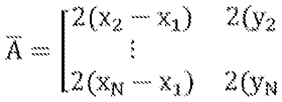
- the sensing member 25PIR- distance C of human DCO which measures 4 (human) positioning the analyte is defined equation: 0 ⁇ (x R - xg ,) 3 ⁇ 4 + (B - y 0 ) 2 and DAO and DBO, DCO subtraction can be obtained: , , , ,
- the present invention can accurately align the position of 4 positions and the direction of displacement by the above definition.
Abstract
Description


Claims
Priority Applications (4)
| Application Number | Priority Date | Filing Date | Title |
|---|---|---|---|
| PCT/CN2013/079281 WO2015003382A1 (zh) | 2013-07-12 | 2013-07-12 | 智能居家定位系统及其定位方法 |
| KR1020157034806A KR20160030095A (ko) | 2013-07-12 | 2013-07-12 | 주택 내 물체를 위한 위치발견 시스템 및 그 방법 |
| EP13888942.3A EP3021502A4 (en) | 2013-07-12 | 2013-07-12 | Intelligent home positioning system and positioning method therefor |
| JP2016524651A JP2016530501A (ja) | 2013-07-12 | 2013-07-12 | スマートハウスの位置測定システム及びその方法 |
Applications Claiming Priority (1)
| Application Number | Priority Date | Filing Date | Title |
|---|---|---|---|
| PCT/CN2013/079281 WO2015003382A1 (zh) | 2013-07-12 | 2013-07-12 | 智能居家定位系统及其定位方法 |
Publications (1)
| Publication Number | Publication Date |
|---|---|
| WO2015003382A1 true WO2015003382A1 (zh) | 2015-01-15 |
Family
ID=52279328
Family Applications (1)
| Application Number | Title | Priority Date | Filing Date |
|---|---|---|---|
| PCT/CN2013/079281 WO2015003382A1 (zh) | 2013-07-12 | 2013-07-12 | 智能居家定位系统及其定位方法 |
Country Status (4)
| Country | Link |
|---|---|
| EP (1) | EP3021502A4 (zh) |
| JP (1) | JP2016530501A (zh) |
| KR (1) | KR20160030095A (zh) |
| WO (1) | WO2015003382A1 (zh) |
Families Citing this family (1)
| Publication number | Priority date | Publication date | Assignee | Title |
|---|---|---|---|---|
| US10242269B2 (en) * | 2017-02-21 | 2019-03-26 | Osram Sylvania Inc. | Occupant position tracking using imaging sensors |
Citations (4)
| Publication number | Priority date | Publication date | Assignee | Title |
|---|---|---|---|---|
| CN101547048A (zh) * | 2008-03-05 | 2009-09-30 | 中科院嘉兴中心微系统所分中心 | 基于无线传感网的室内定位方法 |
| US20100332235A1 (en) * | 2009-06-29 | 2010-12-30 | Abraham Ben David | Intelligent home automation |
| CN102117062A (zh) * | 2009-12-31 | 2011-07-06 | 青岛海尔软件有限公司 | 智能家居系统 |
| CN102984039A (zh) * | 2012-11-06 | 2013-03-20 | 鸿富锦精密工业(深圳)有限公司 | 智能网关、智能家居系统及家电设备的智能控制方法 |
Family Cites Families (8)
| Publication number | Priority date | Publication date | Assignee | Title |
|---|---|---|---|---|
| EP0249292A3 (en) * | 1986-06-10 | 1989-11-15 | THORN EMI Electronics Limited | Radio direction-finding using time of arrival measurements |
| GB2191649A (en) * | 1986-06-10 | 1987-12-16 | Philips Electronic Associated | Radio direction-finding |
| JP2918024B2 (ja) * | 1996-04-15 | 1999-07-12 | 日本電気株式会社 | 車両軌跡追尾装置 |
| JP4093792B2 (ja) * | 2002-04-18 | 2008-06-04 | 富士通株式会社 | 移動無線局の位置を決定する測位システム、プログラムおよび位置決定方法 |
| KR100815260B1 (ko) * | 2006-07-18 | 2008-03-19 | 삼성전자주식회사 | 위상차를 이용한 방위각 측정 장치 및 방법 |
| JP5515647B2 (ja) * | 2009-11-05 | 2014-06-11 | 独立行政法人産業技術総合研究所 | 測位装置 |
| JP5673921B2 (ja) * | 2010-03-31 | 2015-02-18 | 独立行政法人産業技術総合研究所 | 焦電型赤外線センサアレイを用いた測位システム及び測位方法 |
| US8391890B2 (en) * | 2011-06-29 | 2013-03-05 | Alcatel Lucent | Method and apparatus for geo-locating mobile station |
-
2013
- 2013-07-12 EP EP13888942.3A patent/EP3021502A4/en not_active Withdrawn
- 2013-07-12 JP JP2016524651A patent/JP2016530501A/ja active Pending
- 2013-07-12 KR KR1020157034806A patent/KR20160030095A/ko not_active Application Discontinuation
- 2013-07-12 WO PCT/CN2013/079281 patent/WO2015003382A1/zh active Application Filing
Patent Citations (4)
| Publication number | Priority date | Publication date | Assignee | Title |
|---|---|---|---|---|
| CN101547048A (zh) * | 2008-03-05 | 2009-09-30 | 中科院嘉兴中心微系统所分中心 | 基于无线传感网的室内定位方法 |
| US20100332235A1 (en) * | 2009-06-29 | 2010-12-30 | Abraham Ben David | Intelligent home automation |
| CN102117062A (zh) * | 2009-12-31 | 2011-07-06 | 青岛海尔软件有限公司 | 智能家居系统 |
| CN102984039A (zh) * | 2012-11-06 | 2013-03-20 | 鸿富锦精密工业(深圳)有限公司 | 智能网关、智能家居系统及家电设备的智能控制方法 |
Also Published As
| Publication number | Publication date |
|---|---|
| EP3021502A1 (en) | 2016-05-18 |
| JP2016530501A (ja) | 2016-09-29 |
| KR20160030095A (ko) | 2016-03-16 |
| EP3021502A4 (en) | 2017-03-15 |
Similar Documents
| Publication | Publication Date | Title |
|---|---|---|
| JP2019512114A5 (zh) | ||
| JP2015130168A (ja) | 摩擦拡張制御、及び、タッチコントロールパネルのボタンを摩擦拡張制御部へと変換する方法 | |
| JP2008253749A5 (zh) | ||
| KR102055677B1 (ko) | 이동 로봇 및 그 제어방법 | |
| KR20170057038A (ko) | 수면 단계 분석 장치 및 그 동작 방법 | |
| WO2011100519A3 (en) | Biometric sensor for human presence detection and associated methods | |
| US20180259550A1 (en) | Environmental sensor | |
| CN104375515B (zh) | 一种自动跟踪人体的转向装置 | |
| CN105677065B (zh) | 用于显示屏的遥控触控装置及方法 | |
| CN101859211B (zh) | 手指触控定位装置及方法 | |
| CN103486702A (zh) | 基于室内环境或人体表面温度的室内降温控制系统 | |
| US20170164162A1 (en) | LumenGlow™ virtual switch | |
| WO2015003382A1 (zh) | 智能居家定位系统及其定位方法 | |
| KR20190043774A (ko) | 다양한 종류의 센서로부터 데이터를 수집하기 위한 IoT 장치 및 방법 | |
| JP2014191918A (ja) | 環境制御システム | |
| TWI574030B (zh) | Smart home location method | |
| JP2008206908A (ja) | 生体信号検出装置及びそれを用いた電気機器 | |
| CN104023454A (zh) | 一种由座椅控制电灯的系统 | |
| JP2016532795A (ja) | ロック装置の低電力無効化 | |
| CN104280717B (zh) | 智能居家定位系统及其定位方法 | |
| CN201893016U (zh) | 带有微机械传感器的遥控器 | |
| TWI418790B (zh) | 紅外線人體活動感測器架構及偵側人體活動量的方法 | |
| TWI363491B (en) | A sensing controller | |
| US10389149B2 (en) | Sensory and control platform for an automation system | |
| TWI378254B (zh) |
Legal Events
| Date | Code | Title | Description |
|---|---|---|---|
| 121 | Ep: the epo has been informed by wipo that ep was designated in this application |
Ref document number: 13888942 Country of ref document: EP Kind code of ref document: A1 |
|
| ENP | Entry into the national phase |
Ref document number: 2016524651 Country of ref document: JP Kind code of ref document: A |
|
| ENP | Entry into the national phase |
Ref document number: 20157034806 Country of ref document: KR Kind code of ref document: A |
|
| WWE | Wipo information: entry into national phase |
Ref document number: 2013888942 Country of ref document: EP |
|
| NENP | Non-entry into the national phase |
Ref country code: DE |