WO2015001610A1 - Induction heating cooker - Google Patents
Induction heating cooker Download PDFInfo
- Publication number
- WO2015001610A1 WO2015001610A1 PCT/JP2013/068086 JP2013068086W WO2015001610A1 WO 2015001610 A1 WO2015001610 A1 WO 2015001610A1 JP 2013068086 W JP2013068086 W JP 2013068086W WO 2015001610 A1 WO2015001610 A1 WO 2015001610A1
- Authority
- WO
- WIPO (PCT)
- Prior art keywords
- time
- heating
- frequency
- coil
- change amount
- Prior art date
Links
Images


Classifications
-
- H—ELECTRICITY
- H05—ELECTRIC TECHNIQUES NOT OTHERWISE PROVIDED FOR
- H05B—ELECTRIC HEATING; ELECTRIC LIGHT SOURCES NOT OTHERWISE PROVIDED FOR; CIRCUIT ARRANGEMENTS FOR ELECTRIC LIGHT SOURCES, IN GENERAL
- H05B6/00—Heating by electric, magnetic or electromagnetic fields
- H05B6/02—Induction heating
- H05B6/06—Control, e.g. of temperature, of power
- H05B6/062—Control, e.g. of temperature, of power for cooking plates or the like
-
- H—ELECTRICITY
- H05—ELECTRIC TECHNIQUES NOT OTHERWISE PROVIDED FOR
- H05B—ELECTRIC HEATING; ELECTRIC LIGHT SOURCES NOT OTHERWISE PROVIDED FOR; CIRCUIT ARRANGEMENTS FOR ELECTRIC LIGHT SOURCES, IN GENERAL
- H05B2213/00—Aspects relating both to resistive heating and to induction heating, covered by H05B3/00 and H05B6/00
- H05B2213/07—Heating plates with temperature control means
Definitions
- the present invention relates to an induction heating cooker.
- Some conventional induction heating cookers determine the temperature of an object to be heated based on the input current or control amount of an inverter (see, for example, Patent Documents 1 and 2).
- the induction heating cooker of Patent Document 1 has control means for controlling the inverter so that the input current of the inverter is constant, and the temperature of the object to be heated when there is a change in the control amount over a predetermined time within a predetermined time. Judging that the change is large, the output of the inverter is suppressed.
- Patent Document 2 discloses an input current change amount detecting means for detecting an input current change amount, and a temperature determination processing means for determining the temperature of an object to be heated from the input current change amount detected by the input current change amount detecting means.
- An induction heating cooker equipped with the above has been proposed. It is disclosed that when the temperature determining means determines that the heated object has blown up, a stop signal is output to stop heating.
- JP 2008-181892 A (paragraph 0025, FIG. 1) Japanese Patent Laid-Open No. 5-62773 (paragraph 0017, FIG. 1)
- the present invention has been made to solve the above-described problems, and provides an induction heating cooker that can perform an optimal operation efficiently according to the heat load of the contents of the object to be heated. It is intended.
- An induction heating cooker includes a heating coil that induction-heats an object to be heated, a drive circuit that supplies high-frequency power to the heating coil, and a drive circuit that controls driving of the drive circuit and is supplied to the heating coil.
- a control unit that controls high-frequency power, and the control unit is configured to fix at least one of an input current to the drive circuit and a coil current that flows to the heating coil in a state where the drive frequency of the drive circuit is fixed.
- a change amount ( ⁇ I) is obtained, a first time (t1) from the start of power supply to the heating coil until the time change amount ( ⁇ I) becomes equal to or less than a set value is measured, and the first time (t1) ) And the current change amount (I1) of at least one of the input current and the coil current between the first time (t1) and the high frequency power supplied to the heating coil It is characterized by controlling.
- an optimal operation can be efficiently performed according to the heat load of the contents of the object to be heated.
- FIG. 1 It is a disassembled perspective view which shows the induction heating cooking appliance which concerns on Embodiment 1.
- FIG. It is a figure which shows an example of the drive circuit of the induction heating cooking appliance which concerns on Embodiment 1.
- FIG. It is a functional block diagram which shows an example of the control part of the induction heating cooking appliance which concerns on Embodiment 1.
- FIG. It is a load discrimination
- FIG. It is an interphase figure of the input current with respect to the drive frequency at the time of the temperature change of the to-be-heated material of the induction heating cooking appliance which concerns on Embodiment 1.
- FIG. 6 is a diagram illustrating an example of a drive signal for a half-bridge circuit according to Embodiment 2.
- FIG. 6 is a figure which shows a part of drive circuit of the induction heating cooking appliance which concerns on Embodiment 3.
- FIG. 6 is a diagram illustrating an example of a drive signal of a full bridge circuit according to a third embodiment.
- FIG. (Constitution) 1 is an exploded perspective view showing an induction heating cooker according to Embodiment 1.
- an induction heating cooker 100 has a top plate 4 on which an object to be heated 5 such as a pan is placed.
- the top plate 4 includes a first heating port 1, a second heating port 2, and a third heating port 3 as heating ports for inductively heating the object to be heated 5, and corresponds to each heating port.
- the first heating unit 11, the second heating unit 12, and the third heating unit 13 are provided, and the object to be heated 5 can be placed on each heating port to perform induction heating. Is.
- the first heating means 11 and the second heating means 12 are provided side by side on the front side of the main body, and the third heating means 13 is provided at substantially the center on the back side of the main body.
- positioning of each heating port is not restricted to this.
- three heating ports may be arranged side by side in a substantially straight line.
- the top plate 4 is entirely composed of a material that transmits infrared rays, such as heat-resistant tempered glass or crystallized glass, and a rubber packing or a sealing material is interposed between the upper surface opening outer periphery of the induction heating cooker 100 main body. Fixed in a watertight state.
- the top plate 4 has a circular pan showing a rough placement position of the pan corresponding to the heating range (heating port) of the first heating unit 11, the second heating unit 12 and the third heating unit 13.
- the position display is formed by applying paint or printing.
- the heating power and cooking menu (boiling mode, fried food mode when heating the article 5 to be heated by the first heating means 11, the second heating means 12, and the third heating means 13. Etc.) are provided as an input device for setting the operation unit 40a, the operation unit 40b, and the operation unit 40c (hereinafter may be collectively referred to as the operation unit 40). Further, in the vicinity of the operation unit 40, as the notification unit 42, a display unit 41 a, a display unit 41 b, and a display unit 41 c that display the operation state of the induction heating cooker 100 and input / operation contents from the operation unit 40 are provided. Is provided.
- the operation units 40a to 40c and the display units 41a to 41c are not particularly limited, for example, when the operation units 40a and 41c are provided for each heating port, or when the operation unit 40 and the display unit 41 are provided collectively.
- a first heating means 11, a second heating means 12, and a third heating means 13 are provided below the top plate 4 and inside the main body, and each heating means is a heating coil (not shown). Z).
- a drive circuit 50 for supplying high frequency power to the heating coils of the first heating means 11, the second heating means 12, and the third heating means 13, and the drive circuit 50.
- a control unit 45 for controlling the operation of the whole induction heating cooker.
- the heating coil has a substantially circular planar shape, and is configured by winding a conductive wire made of an arbitrary metal with an insulating film (for example, copper, aluminum, etc.) in the circumferential direction. Is supplied to each heating coil, whereby an induction heating operation is performed.
- FIG. 2 is a diagram showing a drive circuit of the induction heating cooker according to the first embodiment.
- the drive circuit 50 is provided for every heating means, the circuit structure may be the same and may be changed for every heating means. In FIG. 2, only one drive circuit 50 is shown. As shown in FIG. 2, the drive circuit 50 includes a DC power supply circuit 22, an inverter circuit 23, and a resonance capacitor 24a.
- the input current detection means 25a detects a current input from the AC power supply (commercial power supply) 21 to the DC power supply circuit 22 and outputs a voltage signal corresponding to the input current value to the control unit 45.
- the DC power supply circuit 22 includes a diode bridge 22a, a reactor 22b, and a smoothing capacitor 22c, converts an AC voltage input from the AC power supply 21 into a DC voltage, and outputs the DC voltage to the inverter circuit 23.
- the inverter circuit 23 is a so-called half-bridge type inverter in which IGBTs 23a and 23b as switching elements are connected in series to the output of the DC power supply circuit 22, and diodes 23c and 23d are parallel to the IGBTs 23a and 23b as flywheel diodes, respectively. It is connected to the.
- the inverter circuit 23 converts the DC power output from the DC power supply circuit 22 into a high-frequency AC power of about 20 kHz to 50 kHz, and supplies the AC power to the resonance circuit including the heating coil 11a and the resonance capacitor 24a.
- the resonance capacitor 24a is connected in series to the heating coil 11a, and this resonance circuit has a resonance frequency according to the inductance of the heating coil 11a, the capacity of the resonance capacitor 24a, and the like.
- the inductance of the heating coil 11a changes according to the characteristics of the metal load when the object to be heated 5 (metal load) is magnetically coupled, and the resonance frequency of the resonance circuit changes according to the change in the inductance.
- the IGBTs 23a and 23b which are switching elements, are composed of, for example, a silicon-based semiconductor, but may be configured using a wide band gap semiconductor such as silicon carbide or a gallium nitride-based material.
- the conduction loss of the switching element can be reduced, and since the heat radiation of the driving circuit is good even when the switching frequency (driving frequency) is high (high speed), the driving circuit Therefore, the size and cost of the driving circuit can be reduced.
- the coil current detection means 25b is connected between the heating coil 11a and the resonance capacitor 24a.
- the coil current detection unit 25 b detects a current flowing through the heating coil 11 a and outputs a voltage signal corresponding to the heating coil current value to the control unit 45.
- the temperature detection means 30 is composed of, for example, a thermistor, and detects the temperature by the heat transferred from the heated object 5 to the top plate 4.
- FIG. 3 is a functional block diagram illustrating an example of a control unit of the induction heating cooker according to the first embodiment.
- the control unit 45 controls the operation of the induction heating cooker 100 including a microcomputer or a DSP (digital signal processor), and includes a drive control unit 31, a load determination unit 32, a drive frequency setting unit 33, a current.
- a change detection unit 34, a period measurement unit 35, and an input / output control unit 36 are provided.
- the drive control means 31 drives the inverter circuit 23 by outputting a drive signal DS to the IGBTs 23a and 23b of the inverter circuit 23 to perform a switching operation. And the drive control means 31 controls the heating to the to-be-heated material 5 by controlling the high frequency electric power supplied to the heating coil 11a.
- the drive signal DS is a signal having a predetermined drive frequency of, for example, about 20 to 50 kHz with a predetermined on-duty ratio (for example, 0.5).
- the load determination means 32 performs a load determination process for the object to be heated 5 and determines the material of the object to be heated 5 as a load.
- the load determination means 32 is, for example, iron, a magnetic material such as SUS430, a high resistance nonmagnetic material such as SUS304, or a low resistance nonmagnetic material such as aluminum or copper. It is roughly classified and judged.
- the drive frequency setting means 33 sets the drive frequency f of the drive signal DS output to the inverter circuit 23 when the inverter circuit 23 supplies the heating coil 11a.
- the drive frequency setting unit 33 has a function of automatically setting the drive frequency f according to the determination result of the load determination unit 32.
- the drive frequency setting means 33 stores a table for determining the drive frequency f according to, for example, the material of the article to be heated 5 and the set thermal power.
- the drive frequency setting means 33 determines the value fd of the drive frequency f by referring to this table when the load determination result and the set thermal power are input.
- the drive frequency setting means 33 sets a frequency higher than the resonance frequency of the resonance circuit so that the input current does not become excessive.
- the drive frequency setting means 33 drives the inverter circuit 23 with the drive frequency f corresponding to the material of the article to be heated 5 based on the load determination result, an increase in input current can be suppressed.
- the reliability of the circuit 23 can be improved by suppressing the high temperature of the circuit 23.
- the predetermined time may be a preset period, or may be a period that can be changed by operating the operation unit 40.
- the period measuring means 35 measures the heating time t1 from the start of power supply to the heating coil 11a until the time change amount ⁇ I becomes equal to or less than the set value in the current change detecting means 34.
- the period measuring means 35 measures the current change amount I1 of the input current during the heating time t1.
- the heating time t1 corresponds to the “first time” in the present invention.
- the drive control means 31 reduces the electric power supplied to the heating coil 11a according to the heating time t1 and the current change amount I1 measured by the period measuring means 35.
- the drive control means 31 sets the increase amount ⁇ f to be larger as the heating time t1 is shorter and the current change amount I1 is smaller.
- the load determination unit 32 of the control unit 45 performs a load determination process.
- FIG. 4 is a graph showing how the input current with respect to the drive frequency changes according to the temperature change of the object to be heated in the drive circuit of FIG.
- the material of the heated object 5 (pan) serving as a load is largely divided into a magnetic material such as iron and SUS430, a high-resistance nonmagnetic material such as SUS304, and a low-resistance nonmagnetic material such as aluminum and copper. Separated.
- the relationship between the coil current and the input current differs depending on the material of the pan load placed on the top plate 4.
- the control unit 45 stores in advance a load determination table in which the relationship between the coil current and the input current shown in FIG. 4 is tabulated. By storing the load determination table therein, the load determination unit 32 can be configured with an inexpensive configuration.
- the control unit 45 drives the inverter circuit 23 with a specific drive signal for load determination, and detects the input current from the output signal of the input current detection means 25a. At the same time, the control unit 45 detects the coil current from the output signal of the coil current detection means 25b.
- the control part 45 determines the material of the to-be-heated object (pan) 5 mounted from the detected coil current and input current, and the load determination table showing the relationship of FIG.
- the control part 45 (load determination means 32) determines the material of the to-be-heated object 5 mounted above the heating coil 11a based on the correlation between an input current and a coil current.
- control unit 45 After performing the above load determination processing, the control unit 45 performs a control operation based on the load determination result.
- the induction heating cooker 100 When the load determination result is a low-resistance non-magnetic material, the induction heating cooker 100 according to the first embodiment cannot be heated. Encourage people to change the pan. At this time, high frequency power is not supplied from the drive circuit 50 to the heating coil 11a.
- the notification means 42 is notified that heating is impossible, and the user is prompted to place the pan. In this case as well, high-frequency power is not supplied to the heating coil 11a.
- these pans are materials that can be heated by the induction heating cooker 100 of the first embodiment, and thus the control unit 45 has determined.
- This drive frequency is set to a frequency higher than the resonance frequency so that the input current does not become excessive.
- the drive frequency can be determined by referring to a frequency table or the like corresponding to the material of the article 5 to be heated and the set heating power, for example.
- the control unit 45 fixes the determined drive frequency and drives the inverter circuit 23 to start the induction heating operation.
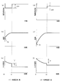
- FIG. 5 is a graph showing how the input current with respect to the drive frequency varies with the temperature change of the object to be heated in the drive circuit of FIG.
- a thin line is a characteristic when the to-be-heated object 5 (pan) is low temperature
- a thick line is a characteristic when the to-be-heated object 5 is high temperature.
- the characteristics change depending on the temperature of the object to be heated 5 because the electrical resistivity of the object to be heated 5 increases and the magnetic permeability decreases due to the temperature rise. This is because the magnetic coupling of the heated object 5 changes.
- a frequency higher than the frequency at which the input current shown in FIG. 5 is maximized is determined as the drive frequency, and this drive frequency is fixed and the inverter circuit 23 is controlled.
- FIG. 6 is an enlarged graph of a portion indicated by a broken line in the graph of FIG.
- the input current value (operating point) at the drive frequency increases as the heated object 5 changes from low temperature to high temperature.
- the point A changes from point A to point B, and the input current gradually decreases as the temperature of the article to be heated 5 rises.
- the control unit 45 obtains a change amount of the input current per time (time change amount ⁇ I) in a state where the drive frequency of the inverter circuit 23 is fixed, and based on this time change amount ⁇ I, the heating object 5 Detect temperature changes.
- the temperature change of the heated object 5 can be detected regardless of the material of the heated object 5. Moreover, since the temperature change of the to-be-heated object 5 can be detected by the change of an input current, the temperature change of the to-be-heated object 5 can be detected at high speed compared with a temperature sensor etc.
- the material of the to-be-heated object 5 mounted above the heating coil 11a is determined, the drive frequency of the inverter circuit 23 is determined according to the material of the to-be-heated object 5, and the inverter circuit 23 is determined by the drive frequency. Drive.
- the inverter circuit 23 can be fixed and driven by the drive frequency according to the material of the to-be-heated material 5, and the increase in input current can be suppressed. Therefore, the high temperature of the inverter circuit 23 can be suppressed and the reliability can be improved.
- control unit 45 performs a load determination process, determines a drive frequency corresponding to the determined pan material, drives the inverter circuit 23 with the determined drive frequency fixed, and performs an induction heating operation. carry out. Then, the control unit 45 determines the completion of boiling based on the time variation ⁇ I of the input current.
- FIG. 7 is a graph showing the temperature and input current over time when driven at the predetermined drive frequency of FIG.
- FIG. 7 the elapsed time and the change of each characteristic when water is thrown into the to-be-heated material 5 and it was made to operate
- FIG. 7 (a) is a drive frequency
- FIG. 7C shows the input current.
- the temperature (water temperature) of the article to be heated 5 gradually increases until it boils, as shown in FIG. 7B. As it rises and boils, the temperature remains constant at about 100 ° C.
- the input current gradually decreases as the temperature of the article to be heated 5 increases, and when the water boils and the temperature becomes constant, the input current also becomes constant. It becomes. That is, when the input current becomes constant, the water boils and the boiling is completed.
- control unit 45 in the first embodiment obtains a change amount (time change amount ⁇ I) of the input current per time with the drive frequency of the inverter circuit 23 fixed, and this time change amount ⁇ I. When becomes below the set value, it is determined that the water heating is completed.
- the setting value information may be set in the control unit 45 in advance or may be input from the operation unit 40 or the like.
- reports that the boiling was completed using the alerting
- the notification means 42 is not particularly limited, for example, displaying the completion of boiling on the display unit 41 or notifying the user by voice using a speaker (not shown).
- the time change amount ⁇ I of the input current is obtained with the drive frequency of the inverter circuit 23 fixed, and this time change amount ⁇ I becomes equal to or less than the set value.
- the notification means 42 notifies the user that the boiling is completed. For this reason, the completion of boiling of water can be notified promptly, and an easy-to-use induction heating cooker can be obtained.
- control unit 45 does not require a high-precision microcomputer when obtaining the time variation ⁇ I of the input current, an induction heating cooker capable of detecting boiling water by an inexpensive method can be obtained.
- control unit 45 performs a load determination process, determines a drive frequency corresponding to the determined pan material, drives the inverter circuit 23 with the determined drive frequency fixed, and performs an induction heating operation. carry out. Then, the control unit 45 determines the completion of boiling based on the time variation ⁇ I of the input current. Further, the control unit 45 cancels the fixing of the driving frequency when the time change amount ⁇ I obtained in a state where the driving frequency of the inverter circuit 23 is fixed becomes equal to or less than the set value.
- control unit 45 varies the drive frequency of the inverter circuit 23 according to the heating time t1 until the time change amount ⁇ I becomes equal to or less than the set value and the current change amount I1 of the input current during the heating time t1.
- the high frequency power supplied to the heating coil 11a is varied. Details of such an operation will be described with reference to FIGS.
- FIG. 8 is a diagram showing the relationship between the drive frequency, temperature, input current, and time in the hot water mode 2 of the induction heating cooker according to the first embodiment.
- FIGS. 8A to 8C show characteristics when the initial temperature of water charged into the object to be heated 5 is high.
- FIG. 8A shows the driving frequency
- FIG. 8B shows the temperature (water temperature).
- 8 (c) shows the input current.
- 8D to 8F show characteristics when the initial temperature of the water charged into the object to be heated 5 is low
- FIG. 8D shows the driving frequency
- FIG. 8E shows the temperature (water temperature).
- 8 (f) shows the input current.
- the initial temperature refers to a temperature in a range from the start of heating to a predetermined period, and is not limited to the start of heating.
- the amount of water (contents) when the initial temperature is high and when the initial temperature is low is substantially the same. That is, the heat load of the contents of the article 5 to be heated in the initial stage of heating is determined by the temperature and amount of the contents. However, if the amounts of the contents are equal, the heat load depends on the initial temperature.
- FIG. 10 is a flowchart illustrating an operation example of the hot water mode 2 of the induction heating cooker according to the first embodiment.
- FIG. 11 is a flowchart showing an operation example of the initial water temperature detection of FIG.
- description will be made based on the flowcharts of FIGS. 10 and 11 with reference to FIGS.
- the heated object 5 is placed on the heating port of the top plate 4 by the user, and an instruction to start heating (heating power input) is given to the operation unit 40.
- the load determination means 32 the material of the to-be-heated object (pan) 5 is determined as a load using the load determination table which shows the relationship between input current and coil current (step ST1).
- the notification means 42 notifies that and the high frequency power is controlled from being supplied from the drive circuit 50 to the heating coil 11a. .
- the drive control means 31 fixes the drive frequency f to fd and the inverter circuit 23 is driven to start the induction heating operation (step ST3). Simultaneously with the start of the induction heating operation by the start of power supply, the measurement of the heating time t1 and the current change amount I1 by the period measuring means 35 is started.
- the current change detecting means 34 calculates the time change amount ⁇ I at a predetermined sampling interval (step ST4). Then, it is determined whether or not the time change amount ⁇ I is equal to or less than a set value (Iref) (step ST5). As the heated object 5 changes from a low temperature to a high temperature, the time change amount ⁇ I decreases (FIGS. 8C and 8F). When water boils and the temperature becomes constant, the input current also becomes constant (FIGS. 8C and 8F). Thereby, in the heating time t1, the control part 45 determines with the time variation
- DELTA change_quantity
- the period measuring means 35 detects the heating time t1 (step ST6). Further, the period measuring means 35 detects the current change amount I1 of the input current between the heating start and the heating time t1 (step ST7). Thereafter, the drive control means 31 performs an initial water temperature detection process, and an increase amount ⁇ f of the drive frequency f is determined from the heating time t1 and the current change amount I1 (step ST8).
- the heating time t1 and the current change amount I1 vary depending on the initial temperature of the water charged into the article 5 to be heated. That is, when the initial temperature (T0) of water is high (FIG. 8B), the heating time t1 is short and the current change amount I1 is small. On the other hand, when the initial temperature of water is low (FIG. 8E), the heating time t1 is long and the current change amount I1 is large. From this, the initial temperature of water (heat load at the initial stage of heating) can be determined based on the heating time t1 and the current change amount I1.
- the controller 45 determines whether or not the heating time t1 is shorter than the predetermined reference time t_ref1 and the current change amount I1 is smaller than the predetermined reference current change amount I_ref1 (step ST81).
- the control part 45 determines with the initial temperature of water being high (strong hot start) (step ST82). For example, if the amount of water is known, it can be estimated that the initial temperature (T0) of water is equal to or higher than T_ref1.
- the control unit 45 determines whether or not the heating time t1 is equal to or less than the predetermined reference time t_ref2 and the current change amount I1 is equal to or less than the predetermined reference current change amount I_ref2. (Step ST83).
- the reference time t_ref2 is longer than the reference time t_ref1.
- the reference current change amount I_ref2 is larger than the reference current change amount I_ref1.
- step ST83 determines that the initial temperature of water is lower (weak hot start) than the strong hot start (step ST84). For example, if the amount of water is known, it can be estimated that the initial temperature (T0) of water is T_ref2 or more and less than T_ref1.
- step ST83 determines that the initial temperature of water is lower (normal heating) than the weak hot start (step ST85). For example, if the amount of water is known, it can be estimated that the initial temperature (T0) of water is less than T_ref2.
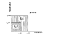
- FIG. 12 is a diagram illustrating the relationship between the reference time and the reference current change amount and the heat load in the initial stage of heating.
- the control unit 45 causes the heating time t1 to be shorter and the current change amount I1 to be smaller according to the heating time t1 and the current change amount I1. It is estimated that the heat load of the contents of the article 5 to be heated in the initial heating stage is small (water temperature is high).
- the reference time and the reference current change amount are each two has been described here, it may be determined by setting three or more reference times and the reference current change amount.
- each reference time and each reference current change amount in the processing of the initial water temperature determination in steps ST81 to ST85 is the water temperature. It is necessary to set according to the amount. For this reason, for example, information on each reference time and each reference current change amount corresponding to the amount of water (content amount) is stored in advance as a table, and information on the amount of water (content amount) is acquired. Thus, each reference time and each reference current change amount may be determined. Thereby, the initial temperature (heat load) of water can be detected more accurately.
- Information on the amount of water may be input from the operation unit 40 or the like. For example, the amount of water may be determined from the weight of the object to be heated 5 using a gravity sensor or the like. Note that the amount of water does not need to be a strict value, and may be, for example, three levels such as small, medium, and large.
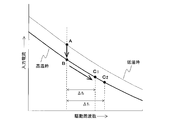
- the drive control means 31 of the control unit 45 releases the fixed drive frequency and increases the drive frequency of the inverter circuit 23 to lower the input current, thereby supplying high-frequency power (thermal power) supplied to the heating coil 11a. ). That is, since the heating power to raise the temperature is not necessary when the object to be heated 5 is kept warm, the amount of heating from the heating coil 11a to the object to be heated 5 is suppressed. At this time, the drive control means 31 of the control part 45 controls the high frequency electric power supplied to the heating coil 11a according to the estimated initial temperature (heat load).
- the increase amount ( ⁇ f) of the drive frequency will be described.
- the drive control means 31 drives the inverter circuit 23 by increasing the drive frequency f to be smaller than ⁇ f2.
- the information on the increase amounts ⁇ f1 and ⁇ f2 of the drive frequency may be set in the control unit 45 in advance, or may be input from the operation unit 40 or the like.
- the increase amounts ⁇ f1 and ⁇ f2 are set so that the water temperature hardly decreases and keeps a constant temperature, and the operating point is changed from the point B to the point C1. (Or point C2). Then, even if the driving frequency f is increased and the thermal power is lowered, the water temperature is hardly lowered and the heat retaining state is maintained.
- the drive of the inverter circuit 23 is controlled to reduce the high frequency power supplied to the heating coil 11a.
- Energy saving can be achieved. That is, when the set value is simply increased to a predetermined driving frequency f as in the conventional case, the optimum heat retaining state cannot be maintained according to the heat load (temperature and amount) of the contents. There is. For example, when the initial temperature of the contents of the article to be heated 5 is low, the amount of heat is insufficient and the temperature gradually decreases, and reheating is required. On the other hand, when the initial temperature of the contents of the article to be heated 5 is high, excessive power is consumed.
- the drive control means 31 determines the increase amount ⁇ f in accordance with the heating time t1 and the current change amount I1, and changes the drive frequency f when the temperature is kept.
- the control unit 45 determines that the heating time t1 is shorter than the reference time t_ref1 (time reference value) and the current change amount I1 is smaller than the reference current change amount I_ref1 (current reference value) (strong hot start).
- the notification means 42 may notify that the hot water has been heated.
- the control unit 45 performs a load determination process, determines a drive frequency corresponding to the determined pan material, drives the inverter circuit 23 with the determined drive frequency fixed, and performs an induction heating operation. carry out. Then, the control unit 45 determines the completion of boiling based on the time variation ⁇ I of the input current. Further, the control unit 45 performs the same control continuously for a predetermined time after the time variation ⁇ I obtained with the drive frequency of the inverter circuit 23 fixed becomes equal to or less than the set value. The fixed frequency is released, the drive frequency of the inverter circuit 23 is varied, and the high frequency power supplied to the heating coil 11a is varied. Details of such an operation will be described with reference to FIGS.
- FIG. 13 is a diagram showing a relationship among drive frequency, temperature, input current, and time in the water heating mode 3 of the induction heating cooker according to the first embodiment.
- FIG. 13 the elapsed time and the change of each characteristic when water is poured into the article 5 to be heated and the water is heated are shown.
- 13 (a) to 13 (c) show characteristics when the initial temperature of water charged into the object to be heated 5 is high.
- FIG. 13 (a) shows the driving frequency
- FIG. 13 (b) shows the temperature (water temperature).
- FIG. 13C shows the input current.
- FIGS. 13D to 13F show characteristics when the initial temperature of the water charged into the object to be heated 5 is low
- FIG. 13D shows the drive frequency
- FIG. 13E shows the temperature (water temperature).
- 13F shows the input current.
- description will be made assuming that the amount of water (contents) when the initial temperature is high and low is approximately the same. That is, the heat load of the contents of the article 5 to be heated in the initial stage of heating is determined by the temperature and amount of the contents. However, if the amounts of the contents are equal, the heat load depends on the initial temperature.
- the input current gradually decreases as the temperature of the object to be heated 5 rises.
- the electrical resistivity and magnetic permeability of the object to be heated 5 change as the temperature rises. This is because the magnetic coupling of the heated object 5 changes. That is, the state in which the input current is constant means that the temperature of the article to be heated 5 (particularly, the portion adjacent to the heating coil 11a) is constant.
- the temperature of the object to be heated 5 reaches about 100 ° C., but the water charged into the object to be heated 5 has a temperature of There may be unevenness and the water as a whole may not have boiled.
- the entire water can be boiled reliably in a short time by driving with the driving frequency fixed until the heating time t2 obtained by adding the additional time ⁇ t to the heating time t1.
- the control unit 45 determines that the boiling of water has been completed.
- the additional time ⁇ t corresponds to the “second time” in the present invention.
- the controller 45 measures the heating time t1 from the start of heating until the input current becomes constant, and according to the length of the heating time t1 and the magnitude of the current change amount I1 until the heating time t1.
- the additional time ⁇ t is changed.
- the heating time t1 and the current change amount I1 are changed by the thermal load (initial temperature and amount) of water charged into the article 5 to be heated. Change. That is, when the initial temperature of water is high (FIG. 13B), the heating time t1 is short and the current change amount I1 is small. When the initial temperature of water is low (FIG. 13 (e)), the heating time t1 becomes long and the current change amount I1 becomes large. When the heating time t1 is short and the current change amount I1 is large, as shown in FIG. 13C, the control unit 45 sets the additional time ⁇ t to be short. On the other hand, when the heating time t1 is long and I1 is large, the control unit 45 sets the additional time ⁇ t to be long as shown in FIG.
- the initial temperature of the water inside the article to be heated 5 is detected by measuring the heating time t1 and the current change amount I1, and the additional time ⁇ t corresponding to the initial temperature of the water is set.
- the additional time ⁇ t corresponding to the initial temperature of the water is set.
- the control unit 45 releases the fixing of the driving frequency and increases the driving frequency of the inverter circuit 23 to reduce the input current, thereby heating the heating coil 11a.
- the high frequency power (thermal power) supplied to is reduced.
- the control for increasing the drive frequency is the same as in the hot water mode 2. Even if the driving frequency is increased to lower the thermal power, the water temperature hardly decreases, so that the operating point moves (changes) from point B to point C1 (point C2) as shown in FIG.
- control unit 45 increases the drive frequency of the inverter circuit 23 and notifies the user of the completion of boiling by the notification means 42. Note that the user may be notified before or after raising the drive frequency.
- the method of controlling the high frequency power (thermal power) by changing the drive frequency has been described.
- the thermal power is controlled by changing the on-duty (on / off ratio) of the switching element of the inverter circuit 23.
- a method may be used.
- FIG. 14 is a diagram illustrating another drive circuit of the induction heating cooker according to the first embodiment.
- a drive circuit 50 shown in FIG. 14 is obtained by adding a resonance capacitor 24b to the configuration shown in FIG.
- Other configurations are the same as those in FIG. 2, and the same parts are denoted by the same reference numerals.
- the resonance circuit is configured by the heating coil 11a and the resonance capacitor, the capacity of the resonance capacitor is determined by the maximum heating power (maximum input power) required for the induction heating cooker.
- the drive circuit 50 shown in FIG. 10 by connecting the resonant capacitors 24a and 24b in parallel, the respective capacities can be halved, and an inexpensive control circuit can be obtained even when two resonant capacitors are used. .
- the current flowing through the coil current detection means 25b is half of the current flowing through the heating coil 11a.
- the capacity coil current detection means 25b can be used, a small and inexpensive control circuit can be obtained, and an inexpensive induction heating cooker can be obtained.
- the example in which the time change amount of the input current detected by the input current detection unit 25a is detected has been described.
- the time of the coil current detected by the coil current detection unit 25b is described.
- the change amount ⁇ I may be detected, or the time change amount ⁇ I of both the input current and the coil current may be detected.
- the half-bridge type inverter circuit 23 has been described. However, a configuration using a full-bridge type or one-stone voltage resonance type inverter may be used.
- the method of using the relationship between the coil current and the primary current in the load determination process in the load determination unit 32 has been described, a method of performing the load determination process by detecting the resonance voltage at both ends of the resonance capacitor may be used.
- the method for determining the load is not particularly limited.
- the load determination unit is configured by setting a threshold for each determination result of the load determination unit 32. Depending on the determination result of 32, the initial temperature of the water charged into the object to be heated may be estimated.
- Embodiment 2 FIG. In the second embodiment, details of the drive circuit 50 in the first embodiment will be described.
- FIG. 15 is a diagram illustrating a part of the drive circuit of the induction heating cooker according to the second embodiment.
- the inverter circuit 23 includes two switching elements (IGBTs 23a and 23b) connected in series between the positive and negative buses, and diodes 23c and 23d connected in antiparallel to the switching elements, respectively. One set of arms is provided.
- the IGBT 23 a and the IGBT 23 b are driven on and off by a drive signal output from the control unit 45.
- the control unit 45 turns off the IGBT 23b while turning on the IGBT 23a, turns on the IGBT 23b while turning off the IGBT 23a, and outputs a drive signal that turns on and off alternately.
- the half bridge inverter which drives the heating coil 11a is comprised by IGBT23a and IGBT23b.
- the IGBT 23a and the IGBT 23b constitute the “half bridge inverter circuit” in the present invention.
- the control part 45 inputs a high frequency drive signal into IGBT23a and IGBT23b according to input electric power (thermal power), and adjusts a heating output.
- the drive signal output to the IGBT 23a and the IGBT 23b is variable in a drive frequency range higher than the resonance frequency of the load circuit constituted by the heating coil 11a and the resonance capacitor 24a, and the current flowing through the load circuit is applied to the load circuit. It is controlled to flow with a lagging phase compared to the voltage to be transmitted.
- FIG. 16 is a diagram illustrating an example of a drive signal of the half bridge circuit according to the second embodiment.
- FIG. 16A shows an example of a drive signal for each switch in the high thermal power state.
- FIG. 16B is an example of the drive signal of each switch in the low thermal power state.
- the control unit 45 outputs a high-frequency drive signal higher than the resonance frequency of the load circuit to the IGBT 23 a and the IGBT 23 b of the inverter circuit 23. By varying the frequency of the drive signal, the output of the inverter circuit 23 increases or decreases.
- the frequency of the high-frequency current supplied to the heating coil 11a approaches the resonance frequency of the load circuit, and the input power to the heating coil 11a increases.
- FIG. 16B when the drive frequency is increased, the frequency of the high-frequency current supplied to the heating coil 11a is separated from the resonance frequency of the load circuit, and the input power to the heating coil 11a is reduced.
- control unit 45 controls the application time of the output voltage of the inverter circuit 23 by changing the on-duty ratio of the IGBT 23a and the IGBT 23b of the inverter circuit 23, along with the control of the input power by changing the drive frequency described above, It is also possible to control the input power to the heating coil 11a.
- the ratio (on duty ratio) of the on-time of the IGBT 23a (the off-time of the IGBT 23b) in one cycle of the drive signal is increased to increase the voltage application time width in one cycle.
- the ratio (on duty ratio) of the on-time of the IGBT 23a (the off-time of the IGBT 23b) in one cycle of the drive signal is reduced to reduce the voltage application time width in one cycle.
- the ratio between the on time T11a of the IGBT 23a (the off time of the IGBT 23b) and the off time T11b of the IGBT 23a (the on time of the IGBT 23b) in one cycle T11 of the drive signal is the same (on duty ratio). Is 50%).
- the ratio between the ON time T12a of the IGBT 23a (the OFF time of the IGBT 23b) and the OFF time T12b of the IGBT 23a (the ON time of the IGBT 23b) in one cycle T12 of the drive signal is the same (ON). The case where the duty ratio is 50%) is illustrated.
- the control circuit 45 23 In the state where the drive frequency of the inverter circuit 23 is fixed when the control unit 45 obtains the time variation ⁇ I per predetermined time of the input current (or coil current) described in the first embodiment, the control circuit 45 23, the on-duty ratio of the IGBT 23a and the IGBT 23b is fixed. Thereby, the time change amount ⁇ I per predetermined time of the input current (or coil current) can be obtained in a state where the input power to the heating coil 11a is constant.
- FIG. 17 is a diagram illustrating a part of the drive circuit of the induction heating cooker according to the third embodiment. Note that FIG. 17 shows only the differences from the drive circuit 50 of the first embodiment.
- two heating coils are provided for one heating port.
- the two heating coils have different diameters and are arranged concentrically.
- the heating coil having a small diameter is referred to as an inner coil 11b, and the heating coil having a large diameter is referred to as an outer coil 11c.
- positioning of a heating coil are not limited to this.
- positioned in the center of a heating port may be sufficient.
- the inverter circuit 23 includes three arms each composed of two switching elements (IGBTs) connected in series between the positive and negative buses and diodes connected to the switching elements in antiparallel.
- IGBTs switching elements
- one of the three sets of arms is called a common arm, and the other two sets are called an inner coil arm and an outer coil arm.
- the common arm is an arm connected to the inner coil 11b and the outer coil 11c, and includes an IGBT 232a, an IGBT 232b, a diode 232c, and a diode 232d.
- the inner coil arm is an arm to which the inner coil 11b is connected, and includes an IGBT 231a, an IGBT 231b, a diode 231c, and a diode 231d.
- the outer coil arm is an arm to which the outer coil 11c is connected, and includes an IGBT 233a, an IGBT 233b, a diode 233c, and a diode 233d.
- the common arm IGBT 232a and IGBT 232b, the inner coil arm IGBT 231a and IGBT 231b, and the outer coil arm IGBT 233a and IGBT 233b are driven on and off by a drive signal output from the control unit 45.
- the controller 45 turns off the IGBT 232b while turning on the IGBT 232a of the common arm, turns on the IGBT 232b while turning off the IGBT 232a, and outputs a drive signal that turns on and off alternately.
- the control unit 45 outputs drive signals for alternately turning on and off the IGBTs 231a and IGBT 231b for the inner coil arms and the IGBTs 233a and IGBT 233b for the outer coil arms.
- the common arm and the inner coil arm constitute a full bridge inverter that drives the inner coil 11b.
- the common arm and the outer coil arm constitute a full bridge inverter that drives the outer coil 11c.
- the “full bridge inverter circuit” in the present invention is constituted by the common arm and the inner coil arm.
- the common arm and the outer coil arm constitute a “full bridge inverter circuit” in the present invention.
- the load circuit constituted by the inner coil 11b and the resonance capacitor 24c is connected between the output point of the common arm (the connection point of the IGBT 232a and the IGBT 232b) and the output point of the arm for the inner coil (the connection point of the IGBT 231a and the IGBT 231b). Is done.
- the load circuit constituted by the outer coil 11c and the resonance capacitor 24d is connected between the output point of the common arm and the output point of the outer coil arm (the connection point between the IGBT 233a and the IGBT 233b).
- the inner coil 11b is a heating coil with a small outer shape wound in a substantially circular shape, and an outer coil 11c is disposed on the outer periphery thereof.
- the coil current flowing through the inner coil 11b is detected by the coil current detection means 25c.
- the coil current detection means 25c detects the peak of the current flowing through the inner coil 11b and outputs a voltage signal corresponding to the peak value of the heating coil current to the control unit 45.
- the coil current flowing through the outer coil 11c is detected by the coil current detection means 25d.
- the peak of the current flowing through the coil current detection means 25d for example, the outer coil 11c, is detected, and a voltage signal corresponding to the peak value of the heating coil current is output to the control unit 45.
- the control unit 45 inputs a high-frequency drive signal to the switching element (IGBT) of each arm according to the input power (thermal power), and adjusts the heating output.
- the drive signal output to the switching elements of the common arm and the inner coil arm varies in a drive frequency range higher than the resonance frequency of the load circuit constituted by the inner coil 11b and the resonance capacitor 24c, and flows to the load circuit. Control is performed so that the current flows in a delayed phase compared to the voltage applied to the load circuit.
- the drive signal output to the switching elements of the common arm and the outer coil arm can be varied within a drive frequency range higher than the resonance frequency of the load circuit constituted by the outer coil 11c and the resonance capacitor 24d, and the load circuit Control is performed so that the current flowing in the current flows in a delayed phase compared to the voltage applied to the load circuit.
- FIG. 18 is a diagram illustrating an example of a drive signal of the full bridge circuit according to the third embodiment.
- FIG. 18A shows an example of the drive signal of each switch and the energization timing of each heating coil in the high thermal power state.
- FIG. 18B is an example of the drive signal of each switch and the energization timing of each heating coil in the low thermal power state.
- the energization timings shown in FIGS. 18A and 18B are related to the potential difference between the output points of each arm (connection point of IGBT and IGBT), and the output points of the inner coil arm and the outer coil A state where the output point of the common arm is lower than the output point of the arm is indicated by “ON”. Further, the state where the output point of the common arm is higher than the output point of the inner coil arm and the output point of the outer coil arm and the state of the same potential are indicated by “OFF”.
- the control unit 45 outputs a high-frequency drive signal higher than the resonance frequency of the load circuit to the IGBTs 232a and IGBTs 232b of the common arm. Further, the control unit 45 outputs a drive signal having a phase advanced from the drive signal of the common arm to the IGBT 231a and IGBT 231b of the inner coil arm and the IGBT 233a and IGBT 233b of the outer coil arm.
- the frequency of the drive signal of each arm is the same frequency, and the on-duty ratio is also the same.
- the positive bus potential or the negative bus potential which is the output of the DC power supply circuit, is switched at a high frequency and output at the output point of each arm (the connection point between the IGBT and IGBT) in accordance with the on / off state of the IGBT and IGBT.
- a potential difference between the output point of the common arm and the output point of the inner coil arm is applied to the inner coil 11b.
- a potential difference between the output point of the common arm and the output point of the outer coil arm is applied to the outer coil 11c. Therefore, the high frequency voltage applied to the inner coil 11b and the outer coil 11c can be adjusted by increasing / decreasing the phase difference between the driving signal to the common arm and the driving signals to the inner coil arm and the outer coil arm.
- the high frequency output current and the input current flowing through the inner coil 11b and the outer coil 11c can be controlled.
- the phase ⁇ between the arms is increased to increase the voltage application time width in one cycle.
- the upper limit of the phase ⁇ between the arms is in the case of reverse phase (phase difference 180 °), and the output voltage waveform at this time is almost a rectangular wave.
- the case where the phase ⁇ between the arms is 180 ° is illustrated.
- the energization on time width T14a and the energization off time width T14b of the inner coil 11b and the outer coil 11c in one cycle T14 of the drive signal have the same ratio.
- the phase ⁇ between the arms is made smaller than in the high thermal power state to reduce the voltage application time width in one cycle.
- the lower limit of the phase ⁇ between the arms is set to a level at which an excessive current does not flow into the switching element and breaks due to the phase of the current flowing in the load circuit at the time of turn-on, for example.
- the frequency and on-duty ratio of the drive signal for each arm are the same as in FIG.
- the energization on time width T14a of the inner coil 11b and the outer coil 11c in one cycle T14 of the drive signal is a time corresponding to the phase ⁇ between the arms.
- the input power (thermal power) to the inner coil 11b and the outer coil 11c can be controlled by the phase difference between the arms.
- the control unit 45 determines whether the drive frequency of the inverter circuit 23 is fixed between the arms. And the on-duty ratio of the switching element of each arm are fixed. Other operations are the same as those in the first embodiment. Thereby, the time change amount ⁇ I per predetermined time of the input current (or coil current) can be obtained in a state where the input power to the inner coil 11b and the outer coil 11c is constant.
- the coil current flowing through the inner coil 11b and the coil current flowing through the outer coil 11c are detected by the coil current detecting means 25c and the coil current detecting means 25d, respectively. Therefore, when both the inner coil 11b and the outer coil 11c are heated, even if either the coil current detection means 25c or the coil current detection means 25d cannot detect the coil current value due to a failure or the like.
- the other detection value makes it possible to detect the time variation ⁇ I of the coil current per predetermined time.
- the control unit 45 also includes a time change amount ⁇ I per predetermined time of the coil current detected by the coil current detection means 25c, and a time change amount ⁇ I per predetermined time of the coil current detected by the coil current detection means 25d.
- the determination operation described in the first embodiment may be performed using the larger one of the time change amounts ⁇ I. Further, each determination operation described in the first embodiment may be performed using an average value of each time change amount ⁇ I. By performing such control, even if the detection accuracy of either the coil current detection unit 25c or the coil current detection unit 25d is low, the time change amount ⁇ I per predetermined time of the coil current is obtained more accurately. be able to.
- the IH cooking heater has been described as an example of the induction heating cooker of the present invention.
- the present invention is not limited to this.
- the present invention can be applied to any induction heating cooker that employs an induction heating method, such as a rice cooker that performs cooking by induction heating.
Abstract
Description
(構成)
図1は、実施の形態1に係る誘導加熱調理器を示す分解斜視図である。
図1に示すように、誘導加熱調理器100の上部には、鍋などの被加熱物5が載置される天板4を有している。天板4には、被加熱物5を誘導加熱するための加熱口として、第一の加熱口1、第二の加熱口2、第三の加熱口3とを備え、各加熱口に対応して、第一の加熱手段11、第二の加熱手段12、第三の加熱手段13を備えており、それぞれの加熱口に対して被加熱物5を載置して誘導加熱を行うことができるものである。
本実施の形態1では、本体の手前側に左右に並べて第一の加熱手段11と第二の加熱手段12が設けられ、本体の奥側ほぼ中央に第三の加熱手段13が設けられている。
なお、各加熱口の配置はこれに限るものではない。例えば、3つの加熱口を略直線状に横に並べて配置しても良い。また、第一の加熱手段11の中心と第二の加熱手段12の中心との奥行き方向の位置が異なるように配置しても良い。
(Constitution)
1 is an exploded perspective view showing an induction heating cooker according to
As shown in FIG. 1, an
In the first embodiment, the first heating means 11 and the second heating means 12 are provided side by side on the front side of the main body, and the third heating means 13 is provided at substantially the center on the back side of the main body. .
In addition, arrangement | positioning of each heating port is not restricted to this. For example, three heating ports may be arranged side by side in a substantially straight line. Moreover, you may arrange | position so that the position of the depth direction of the center of the 1st heating means 11 and the center of the 2nd heating means 12 may differ.
制御部45は、マイコン又はDSP(デジタル・シグナル・プロセッサ)等からなる誘導加熱調理器100の動作を制御するものであって、駆動制御手段31、負荷判定手段32、駆動周波数設定手段33、電流変化検出手段34、期間計測手段35、入出力制御手段36を備えている。 FIG. 3 is a functional block diagram illustrating an example of a control unit of the induction heating cooker according to the first embodiment. The
The
なお、加熱時間t1は、本発明における「第一の時間」に相当する。 The period measuring means 35 measures the heating time t1 from the start of power supply to the
The heating time t1 corresponds to the “first time” in the present invention.
次に、実施の形態1に係る誘導加熱調理器100の動作例について説明する。
まず、天板4の加熱口に載置された被加熱物5を、操作部40により設定された火力により誘導加熱する場合の動作について説明する。 (Operation)
Next, an operation example of the
First, the operation in the case where the object to be heated 5 placed on the heating port of the top plate 4 is induction-heated by the thermal power set by the
ここで、負荷となる被加熱物5(鍋)の材質は、鉄、SUS430等の磁性材と、SUS304等の高抵抗非磁性材と、アルミ、銅等の低抵抗非磁性材と、に大別される。 FIG. 4 is a graph showing how the input current with respect to the drive frequency changes according to the temperature change of the object to be heated in the drive circuit of FIG.
Here, the material of the heated object 5 (pan) serving as a load is largely divided into a magnetic material such as iron and SUS430, a high-resistance nonmagnetic material such as SUS304, and a low-resistance nonmagnetic material such as aluminum and copper. Separated.
図5に示すように、被加熱物5の温度によって特性が変化するのは、温度上昇によって被加熱物5の電気抵抗率が増加し、また透磁率が低下することで、加熱コイル11aと被加熱物5の磁気結合が変化するためである。 FIG. 5 is a graph showing how the input current with respect to the drive frequency varies with the temperature change of the object to be heated in the drive circuit of FIG. In FIG. 5, a thin line is a characteristic when the to-be-heated object 5 (pan) is low temperature, and a thick line is a characteristic when the to-
As shown in FIG. 5, the characteristics change depending on the temperature of the object to be heated 5 because the electrical resistivity of the object to be heated 5 increases and the magnetic permeability decreases due to the temperature rise. This is because the magnetic coupling of the
前述の負荷判定処理で判定した鍋材質に応じた駆動周波数を固定してインバータ回路23を制御すると、被加熱物5が低温から高温になるにつれて、当該駆動周波数における入力電流値(動作点)が、点Aから点Bに変化し、被加熱物5の温度上昇に伴い、入力電流が徐々に低下していく。
このとき、制御部45は、インバータ回路23の駆動周波数を固定した状態で、入力電流の時間当たりの変化量(時間変化量ΔI)を求め、この時間変化量ΔIに基づき、被加熱物5の温度変化を検出する。 6 is an enlarged graph of a portion indicated by a broken line in the graph of FIG.
When the
At this time, the
次に、操作部40により調理メニュー(動作モード)として、被加熱物5に投入された水の湯沸し動作を行う湯沸しモードが選択された場合の動作について説明する。 (Water heating mode 1)
Next, an operation when the water heating mode for performing the water heating operation of the water charged in the article to be heated 5 is selected as the cooking menu (operation mode) by the
図7においては、被加熱物5内に水が投入され、湯沸しモードで動作させた時の経過時間と各特性の変化を示しており、図7(a)は駆動周波数、図7(b)は温度(水温)、図7(c)は入力電流を示す。 FIG. 7 is a graph showing the temperature and input current over time when driven at the predetermined drive frequency of FIG.
In FIG. 7, the elapsed time and the change of each characteristic when water is thrown into the to-
なお、設定値の情報は予め制御部45に設定しても良いし、操作部40等から入力可能としても良い。 For this reason, the
The setting value information may be set in the
このため、水の湯沸し完了を速やかに報知することができ、使い勝手の良い誘導加熱調理器を得ることができる。 As described above, in the water heating mode in which the water boiling operation is set, the time change amount ΔI of the input current is obtained with the drive frequency of the
For this reason, the completion of boiling of water can be notified promptly, and an easy-to-use induction heating cooker can be obtained.
次に、操作部40により湯沸しモードが選択された場合の別の制御動作について説明する。 (Hot water mode 2)
Next, another control operation when the water heating mode is selected by the
さらに、制御部45は、インバータ回路23の駆動周波数を固定した状態で求めた時間変化量ΔIが、設定値以下となった場合、駆動周波数の固定を解除する。そして、制御部45は、時間変化量ΔIが設定値以下になるまでの加熱時間t1と、加熱時間t1の間における入力電流の電流変化量I1とに応じて、インバータ回路23の駆動周波数を可変して、加熱コイル11aに供給される高周波電力を可変させる。このような動作の詳細を図8~図11により説明する。 Similarly to the above-described operation, the
Further, the
図8においては、被加熱物5内に水が投入され湯沸しを行った際の経過時間と各特性の変化を示している。
図8(a)~(c)は、被加熱物5内に投入された水の初期温度が高い時の特性であり、図8(a)は駆動周波数、図8(b)は温度(水温)、図8(c)は入力電流を示している。
図8(d)~(f)は、被加熱物5内に投入された水の初期温度が低い時の特性であり、図8(d)は駆動周波数、図8(e)は温度(水温)、図8(f)は入力電流を示している。
図9は、図5の破線で示した部分を拡大した図である。
ここで、初期温度とは、加熱を開始してから所定の期間までの範囲における温度を指し、加熱開始時に限定するものではない。
なお、図8においては、初期温度が高い場合と低い場合の水(内容物)の量が略同等であるものとして説明する。即ち、加熱初期段階における被加熱物5の内容物の熱負荷は、内容物の温度と量とによって定まるものであるが、内容物の量が同等であれば熱負荷は初期温度に依存する。 FIG. 8 is a diagram showing the relationship between the drive frequency, temperature, input current, and time in the
In FIG. 8, the elapsed time and the change of each characteristic when water is thrown into the to-
FIGS. 8A to 8C show characteristics when the initial temperature of water charged into the object to be heated 5 is high. FIG. 8A shows the driving frequency, and FIG. 8B shows the temperature (water temperature). 8 (c) shows the input current.
8D to 8F show characteristics when the initial temperature of the water charged into the object to be heated 5 is low, FIG. 8D shows the driving frequency, and FIG. 8E shows the temperature (water temperature). 8 (f) shows the input current.
FIG. 9 is an enlarged view of a portion indicated by a broken line in FIG.
Here, the initial temperature refers to a temperature in a range from the start of heating to a predetermined period, and is not limited to the start of heating.
In FIG. 8, description will be made assuming that the amount of water (contents) when the initial temperature is high and when the initial temperature is low is substantially the same. That is, the heat load of the contents of the
図11は、図11の初期水温検知の動作例を示すフローチャートである。
以下、図10、図11のフローチャートに基づき、図8、図9を参照しつつ説明する。 FIG. 10 is a flowchart illustrating an operation example of the
FIG. 11 is a flowchart showing an operation example of the initial water temperature detection of FIG.
Hereinafter, description will be made based on the flowcharts of FIGS. 10 and 11 with reference to FIGS.
そして、時間変化量ΔIが設定値(Iref)以下であるか否かが判断される(ステップST5)。被加熱物5が低温から高温になるにつれて、時間変化量ΔIが小さくなっていく(図8(c)、(f))。水が沸騰して温度が一定となると、入力電流も一定となる(図8(c)、(f))。これにより、加熱時間t1において、制御部45は、入力電流の時間変化量ΔIが設定値(Iref)以下となったと判定する。 While the induction heating operation is performed, the current change detecting means 34 calculates the time change amount ΔI at a predetermined sampling interval (step ST4).
Then, it is determined whether or not the time change amount ΔI is equal to or less than a set value (Iref) (step ST5). As the
その後、駆動制御手段31は、初期水温検知の処理を実施し、加熱時間t1と電流変化量I1とから駆動周波数fの増加量Δfが決定される(ステップST8)。 When the time change amount ΔI becomes equal to or less than the set value, the period measuring means 35 detects the heating time t1 (step ST6). Further, the period measuring means 35 detects the current change amount I1 of the input current between the heating start and the heating time t1 (step ST7).
Thereafter, the drive control means 31 performs an initial water temperature detection process, and an increase amount Δf of the drive frequency f is determined from the heating time t1 and the current change amount I1 (step ST8).
このことから、加熱時間t1と電流変化量I1とに基づき、水の初期温度(加熱初期段階の熱負荷)を判定することができる。 Since the driving frequency is fixed during the heating time t1, the heating time t1 and the current change amount I1 vary depending on the initial temperature of the water charged into the
From this, the initial temperature of water (heat load at the initial stage of heating) can be determined based on the heating time t1 and the current change amount I1.
制御部45は、加熱時間t1が所定の参照時間t_ref1よりも短く、かつ、電流変化量I1が所定の参照電流変化量I_ref1よりも小さいか否かを判定する(ステップST81)。 Details of this initial water temperature detection process will be described with reference to FIG.
The
図12に示すように、ステップST81~ST85の初期水温判定の処理により、加熱時間t1及び電流変化量I1に応じて、制御部45は、加熱時間t1が短く、電流変化量I1が小さい程、加熱初期段階における被加熱物5の内容物の熱負荷が小さい(水の温度が高い)と推定する。
なお、ここでは、参照時間及び参照電流変化量がそれぞれ2つ場合について説明したが、3つ以上の参照時間及び参照電流変化量を設定して判定してもよい。 FIG. 12 is a diagram illustrating the relationship between the reference time and the reference current change amount and the heat load in the initial stage of heating.
As shown in FIG. 12, according to the initial water temperature determination process in steps ST81 to ST85, the
In addition, although the case where the reference time and the reference current change amount are each two has been described here, it may be determined by setting three or more reference times and the reference current change amount.
このとき、制御部45の駆動制御手段31は、推定した初期温度(熱負荷)に応じて加熱コイル11aに供給される高周波電力を制御する。駆動制御手段31においてインバータ回路23の駆動周波数f=fdからf=fd+Δfに変更され、低下した高周波電力がインバータ回路23から加熱コイル11aに供給される(ステップST86、図8(a)(d))。 Next, the drive control means 31 of the
At this time, the drive control means 31 of the
加熱時間t1が短く、電流変化量I1が小さい場合、即ち、強ホットスタートの場合、図8(a)に示すように、駆動制御手段31は、駆動周波数fを大きく増加させ、駆動周波数f=fd+Δf1の駆動信号DSでインバータ回路23を駆動する。
一方、加熱時間t1が長く、電流変化量I1が大きい場合、即ち、弱ホットスタートの場合、図8(d)に示すように、駆動制御手段31は、駆動周波数fを小さく増加させ、駆動周波数f=fd+Δf2の駆動信号DSでインバータ回路23を駆動する。
なお、加熱時間t1がさらに長く、電流変化量I1がさらに大きい場合、即ち、通常加熱の場合、駆動制御手段31は、駆動周波数fをΔf2よりも小さく増加させてインバータ回路23を駆動する。
なお、駆動周波数の増加量Δf1、Δf2の情報は予め制御部45に設定しても良いし、操作部40等から入力可能としても良い。 Here, the increase amount (Δf) of the drive frequency will be described.
When the heating time t1 is short and the current change amount I1 is small, that is, in the case of strong hot start, as shown in FIG. 8A, the drive control means 31 greatly increases the drive frequency f, and the drive frequency f = The
On the other hand, when the heating time t1 is long and the current change amount I1 is large, that is, in the case of weak hot start, as shown in FIG. 8D, the drive control means 31 increases the drive frequency f to a small value, The
When the heating time t1 is longer and the current change amount I1 is larger, that is, in the case of normal heating, the drive control means 31 drives the
The information on the increase amounts Δf1 and Δf2 of the drive frequency may be set in the
このため、無駄な電力供給を抑えつつ、保温動作を行うことができる省エネで使い勝手の良い誘導加熱調理器を得ることができる。
特に、湯沸し(水の沸騰)モードの場合では、必要以上に火力を上げても水温が100℃以上になることはないため、駆動周波数fを上げて火力を低下させても、沸騰状態を維持することができる。 Thus, for the high-frequency power (thermal power) input after the heating time t1, when the thermal load at the initial stage of heating is small (the initial temperature is high), the thermal power is set low, and the thermal load at the initial stage of heating is large ( If the initial temperature is low), set the heating power higher.
For this reason, it is possible to obtain an energy-saving and easy-to-use induction heating cooker that can perform a heat retaining operation while suppressing wasteful power supply.
In particular, in the case of boiling water (boiling water) mode, even if the heating power is increased more than necessary, the water temperature will not exceed 100 ° C. Therefore, even if the driving frequency f is increased and the heating power is decreased, the boiling state is maintained. can do.
すなわち、従来のように、設定値になった際に所定の駆動周波数fまで単に増加させた場合、内容物の熱負荷(温度及び量)に応じて最適な保温状態を保つことができないという問題がある。例えば、被加熱物5の内容物の初期温度が低い場合には熱量が足りずに温度が徐々に低下してしまい再加熱が必要となってしまう。一方で被加熱物5の内容物の初期温度が高い場合には過剰な電力を消費してしまう。
本実施の形態1においては、被加熱物5の内容物の熱負荷(温度及び量)が異なれば駆動周波数fが同一(火力が同一)であっても加熱時間t1及び電流変化量I1が異なる点に着目し、駆動制御手段31が加熱時間t1及び電流変化量I1に応じて増加量Δfを決定し、保温する際の駆動周波数fを変化させる。これにより、被加熱物5の熱負荷に即して必要十分な電力を加熱コイル11aに供給することができるため、効率よく省エネ化を図ることができる。 As described above, when the time variation ΔI of the input current becomes equal to or less than the set value, the drive of the
That is, when the set value is simply increased to a predetermined driving frequency f as in the conventional case, the optimum heat retaining state cannot be maintained according to the heat load (temperature and amount) of the contents. There is. For example, when the initial temperature of the contents of the article to be heated 5 is low, the amount of heat is insufficient and the temperature gradually decreases, and reheating is required. On the other hand, when the initial temperature of the contents of the article to be heated 5 is high, excessive power is consumed.
In the first embodiment, if the heat load (temperature and amount) of the contents of the article to be heated 5 is different, the heating time t1 and the current change amount I1 are different even if the drive frequency f is the same (the same thermal power). Focusing on this point, the drive control means 31 determines the increase amount Δf in accordance with the heating time t1 and the current change amount I1, and changes the drive frequency f when the temperature is kept. Thereby, since necessary and sufficient electric power can be supplied to the
なお、制御部45は、加熱時間t1が参照時間t_ref1(時間基準値)より短く、かつ、電流変化量I1が参照電流変化量I_ref1(電流基準値)より小さい場合(強ホットスタート)には、時間変化量ΔIが設定値以下となった時に、湯沸しが完了した旨を報知手段42により報知させても良い。 Refer to FIG. 10 again. After step ST8, the drive control means 31 notifies the user of the completion of boiling by the notifying
The
次に、操作部40により湯沸しモードが選択された場合の別の制御動作について説明する。 (Water heating mode 3)
Next, another control operation when the water heating mode is selected by the
さらに、制御部45は、インバータ回路23の駆動周波数を固定した状態で求めた時間変化量ΔIが、設定値以下となった後、所定時間継続して同じ制御を行い、所定時間経過後、駆動周波数の固定を解除し、インバータ回路23の駆動周波数を可変して、加熱コイル11aに供給される高周波電力を可変させる。このような動作の詳細を図9及び図13により説明する。 Similarly to the above-described operation, the
Further, the
図13においては、被加熱物5内に水が投入され湯沸しを行った際の経過時間と各特性の変化を示している。
図13(a)~(c)は、被加熱物5内に投入された水の初期温度が高い時の特性であり、図13(a)は駆動周波数、図13(b)は温度(水温)、図13(c)は入力電流を示している。
図13(d)~(f)は、被加熱物5内に投入された水の初期温度が低い時の特性であり、図13(d)は駆動周波数、図13(e)は温度(水温)、図13(f)は入力電流を示している。
なお、図13においては、初期温度が高い場合と低い場合の水(内容物)の量が略同等であるものとして説明する。即ち、加熱初期段階における被加熱物5の内容物の熱負荷は、内容物の温度と量とによって定まるものであるが、内容物の量が同等であれば熱負荷は初期温度に依存する。 FIG. 13 is a diagram showing a relationship among drive frequency, temperature, input current, and time in the water heating mode 3 of the induction heating cooker according to the first embodiment.
In FIG. 13, the elapsed time and the change of each characteristic when water is poured into the
13 (a) to 13 (c) show characteristics when the initial temperature of water charged into the object to be heated 5 is high. FIG. 13 (a) shows the driving frequency, and FIG. 13 (b) shows the temperature (water temperature). FIG. 13C shows the input current.
FIGS. 13D to 13F show characteristics when the initial temperature of the water charged into the object to be heated 5 is low, FIG. 13D shows the drive frequency, and FIG. 13E shows the temperature (water temperature). FIG. 13F shows the input current.
In FIG. 13, description will be made assuming that the amount of water (contents) when the initial temperature is high and low is approximately the same. That is, the heat load of the contents of the
この湯沸しモード3では、加熱時間t1に付加時間Δtを加えた加熱時間t2まで、駆動周波数を固定した状態で駆動することで、短時間で確実に水全体を沸騰させることができる。加熱時間t2において、制御部45は湯沸しが完了したと判断する。
なお、付加時間Δtは、本発明における「第二の時間」に相当する。 In the heating time t1 in which the input current is constant in FIGS. 13C and 13F, the temperature of the object to be heated 5 reaches about 100 ° C., but the water charged into the object to be heated 5 has a temperature of There may be unevenness and the water as a whole may not have boiled.
In the hot water boiling mode 3, the entire water can be boiled reliably in a short time by driving with the driving frequency fixed until the heating time t2 obtained by adding the additional time Δt to the heating time t1. At the heating time t2, the
The additional time Δt corresponds to the “second time” in the present invention.
付加時間Δtは、加熱時間t2と加熱時間t1との差分であり、Δt=t2-t1で表させる。湯沸しモード3では、制御部45により、加熱開始から入力電流が一定となるまでの加熱時間t1を計測し、加熱時間t1の長さと、加熱時間t1までの電流変化量I1の大きさに応じて付加時間Δtを変化させる。 Here, the heating time t2 and the additional time Δt will be described.
The additional time Δt is a difference between the heating time t2 and the heating time t1, and is expressed by Δt = t2−t1. In the hot water heating mode 3, the
そこで、湯沸しモード3では、加熱時間t1及び電流変化量I1を計測することで被加熱物5の内部の水の初期温度を検出し、水の初期温度に応じた付加時間Δtを設定することで、沸騰に必要な無駄な電力供給を抑制すると共に、短時間で確実に水全体を沸騰させることができる省エネでかつ使い勝手の良い誘導加熱調理器を得ることができる。 When the initial temperature of the water is low, the temperature unevenness of the water inside the article to be heated 5 is often larger than when it is high, and more time is required to boil the whole water reliably. .
Therefore, in the water heating mode 3, the initial temperature of the water inside the article to be heated 5 is detected by measuring the heating time t1 and the current change amount I1, and the additional time Δt corresponding to the initial temperature of the water is set. In addition, it is possible to obtain an energy-saving and easy-to-use induction heating cooker that can suppress wasteful power supply necessary for boiling and can surely boil the entire water in a short time.
続いて別の駆動回路を使用した例について説明する。
図14は、実施の形態1に係る誘導加熱調理器の別の駆動回路を示す図である。
図14に示す駆動回路50は、図2に示した構成に、共振コンデンサ24bを付加したものである。なお、その他の構成は図2と同様であり、同一部分には同一の符号を付する。 (Configuration example of another drive circuit)
Next, an example using another drive circuit will be described.
FIG. 14 is a diagram illustrating another drive circuit of the induction heating cooker according to the first embodiment.
A
本実施の形態2では、上記実施の形態1における駆動回路50の詳細について説明する。
In the second embodiment, details of the
図15に示すように、インバータ回路23は、正負母線間に直列に接続された2個のスイッチング素子(IGBT23a、23b)と、そのスイッチング素子にそれぞれ逆並列に接続されたダイオード23c、23dとによって構成されるアームを1組備えている。 FIG. 15 is a diagram illustrating a part of the drive circuit of the induction heating cooker according to the second embodiment. In FIG. 15, only a part of the configuration of the
As shown in FIG. 15, the
制御部45は、IGBT23aをオンさせている間はIGBT23bをオフ状態にし、IGBT23aをオフさせている間はIGBT23bをオン状態にし、交互にオンオフする駆動信号を出力する。
これにより、IGBT23aとIGBT23bとにより、加熱コイル11aを駆動するハーフブリッジインバータを構成する。 The
The
Thereby, the half bridge inverter which drives the
制御部45は、インバータ回路23のIGBT23aおよびIGBT23bに、負荷回路の共振周波数よりも高い高周波の駆動信号を出力する。
この駆動信号の周波数を可変することにより、インバータ回路23の出力が増減する。 FIG. 16 is a diagram illustrating an example of a drive signal of the half bridge circuit according to the second embodiment. FIG. 16A shows an example of a drive signal for each switch in the high thermal power state. FIG. 16B is an example of the drive signal of each switch in the low thermal power state.
The
By varying the frequency of the drive signal, the output of the
また、図16(b)に示すように、駆動周波数を上昇させると、加熱コイル11aに供給される高周波電流の周波数が、負荷回路の共振周波数から離れ、加熱コイル11aへの投入電力が減少する。 For example, as shown in FIG. 16A, when the drive frequency is lowered, the frequency of the high-frequency current supplied to the
As shown in FIG. 16B, when the drive frequency is increased, the frequency of the high-frequency current supplied to the
火力を増加させる場合には、駆動信号の1周期におけるIGBT23aのオン時間(IGBT23bのオフ時間)の比率(オンデューティ比)を大きくして、1周期における電圧印加時間幅を増加させる。
また、火力を低下させる場合には、駆動信号の1周期におけるIGBT23aのオン時間(IGBT23bのオフ時間)の比率(オンデューティ比)を小さくして、1周期における電圧印加時間幅を減少させる。 Furthermore, the
When increasing the thermal power, the ratio (on duty ratio) of the on-time of the
When reducing the thermal power, the ratio (on duty ratio) of the on-time of the
また、図16(b)の例では、駆動信号の1周期T12におけるIGBT23aのオン時間T12a(IGBT23bのオフ時間)と、IGBT23aのオフ時間T12b(IGBT23bのオン時間)との比率が同じ場合(オンデューティ比が50%)の場合を図示している。 In the example of FIG. 16A, the ratio between the on time T11a of the
In the example of FIG. 16B, the ratio between the ON time T12a of the
これにより、加熱コイル11aへの投入電力が一定の状態で、入力電流(又はコイル電流)の所定時間当たりの時間変化量ΔIを求めることができる。 In the state where the drive frequency of the
Thereby, the time change amount ΔI per predetermined time of the input current (or coil current) can be obtained in a state where the input power to the
本実施の形態3においては、フルブリッジ回路を用いたインバータ回路23について説明を行う。
図17は、実施の形態3に係る誘導加熱調理器の駆動回路の一部を示す図である。なお、図17においては、上記実施の形態1の駆動回路50との相違点のみを図示している。
本実施の形態3では、1つの加熱口に対して2つの加熱コイルが設けられている。2つの加熱コイルは、例えば、それぞれ直径が異なり、同心円状に配置されている。ここでは、直径の小さい加熱コイルを内コイル11bと称し、直径の大きい加熱コイルを外コイル11cと称する。
なお、加熱コイルの数及び配置は、これに限定されない。例えば、加熱口の中央に配置した加熱コイルの周囲に複数の加熱コイルを配置する構成でも良い。 Embodiment 3 FIG.
In the third embodiment, an
FIG. 17 is a diagram illustrating a part of the drive circuit of the induction heating cooker according to the third embodiment. Note that FIG. 17 shows only the differences from the
In the third embodiment, two heating coils are provided for one heating port. For example, the two heating coils have different diameters and are arranged concentrically. Here, the heating coil having a small diameter is referred to as an
In addition, the number and arrangement | positioning of a heating coil are not limited to this. For example, the structure which arrange | positions a some heating coil around the heating coil arrange | positioned in the center of a heating port may be sufficient.
内コイル用アームは、内コイル11bが接続されたアームで、IGBT231a、IGBT231b、ダイオード231c、及びダイオード231dで構成されている。
外コイル用アームは、外コイル11cが接続されたアームで、IGBT233a、IGBT233b、ダイオード233c、及びダイオード233dで構成されている。 The common arm is an arm connected to the
The inner coil arm is an arm to which the
The outer coil arm is an arm to which the
同様に、制御部45は、内コイル用アームのIGBT231aとIGBT231b、外コイル用アームのIGBT233aとIGBT233bを交互にオンオフする駆動信号を出力する。
これにより、共通アームと内コイル用アームとにより、内コイル11bを駆動するフルブリッジインバータを構成する。また、共通アームと外コイル用アームとにより、外コイル11cを駆動するフルブリッジインバータを構成する。 The
Similarly, the
As a result, the common arm and the inner coil arm constitute a full bridge inverter that drives the
外コイル11cおよび共振コンデンサ24dにより構成される負荷回路は、共通アームの出力点と、外コイル用アームの出力点(IGBT233aとIGBT233bの接続点)との間に接続されている。 The load circuit constituted by the
The load circuit constituted by the
内コイル11bに流れるコイル電流は、コイル電流検出手段25cにより検出する。コイル電流検出手段25cは、例えば、内コイル11bに流れる電流のピークを検出し、加熱コイル電流のピーク値に相当する電圧信号を制御部45に出力する。
外コイル11cに流れるコイル電流は、コイル電流検出手段25dにより検出する。コイル電流検出手段25d、例えば、外コイル11cに流れる電流のピークを検出し、加熱コイル電流のピーク値に相当する電圧信号を制御部45に出力する。 The
The coil current flowing through the
The coil current flowing through the
共通アーム及び内コイル用アームのスイッチング素子に出力される駆動信号は、内コイル11bおよび共振コンデンサ24cにより構成される負荷回路の共振周波数よりも高い駆動周波数の範囲で可変して、負荷回路に流れる電流が負荷回路に印加される電圧と比較して遅れ位相で流れるように制御する。
また、共通アーム及び外コイル用アームのスイッチング素子に出力される駆動信号は、外コイル11cおよび共振コンデンサ24dにより構成される負荷回路の共振周波数よりも高い駆動周波数の範囲で可変して、負荷回路に流れる電流が負荷回路に印加される電圧と比較して遅れ位相で流れるように制御する。 The
The drive signal output to the switching elements of the common arm and the inner coil arm varies in a drive frequency range higher than the resonance frequency of the load circuit constituted by the
Further, the drive signal output to the switching elements of the common arm and the outer coil arm can be varied within a drive frequency range higher than the resonance frequency of the load circuit constituted by the
図18(a)は高火力状態における各スイッチの駆動信号と各加熱コイルの通電タイミングの例である。
図18(b)は低火力状態における各スイッチの駆動信号と各加熱コイルの通電タイミングの例である。
なお、図18(a)及び(b)に示す通電タイミングは、各アームの出力点(IGBTとIGBTの接続点)の電位差に関係するものであり、内コイル用アームの出力点および外コイル用アームの出力点に対して共通アームの出力点が低い状態を「ON」で示している。また、内コイル用アームの出力点および外コイル用アームの出力点に対して共通アームの出力点が高い状態および同電位の状態を「OFF」で示している。 FIG. 18 is a diagram illustrating an example of a drive signal of the full bridge circuit according to the third embodiment.
FIG. 18A shows an example of the drive signal of each switch and the energization timing of each heating coil in the high thermal power state.
FIG. 18B is an example of the drive signal of each switch and the energization timing of each heating coil in the low thermal power state.
Note that the energization timings shown in FIGS. 18A and 18B are related to the potential difference between the output points of each arm (connection point of IGBT and IGBT), and the output points of the inner coil arm and the outer coil A state where the output point of the common arm is lower than the output point of the arm is indicated by “ON”. Further, the state where the output point of the common arm is higher than the output point of the inner coil arm and the output point of the outer coil arm and the state of the same potential are indicated by “OFF”.
また、制御部45は、共通アームの駆動信号より位相の進んだ駆動信号を、内コイル用アームのIGBT231aとIGBT231b、外コイル用アームのIGBT233aとIGBT233bに出力する。なお、各アームの駆動信号の周波数は同一周波数であり、オンデューティ比も同一である。 As shown in FIG. 18, the
Further, the
したがって、共通アームへの駆動信号と、内コイル用アームおよび外コイル用アームへの駆動信号との位相差を増減することにより、内コイル11bおよび外コイル11cに印加する高周波電圧を調整することができ、内コイル11bと外コイル11cに流れる高周波出力電流と入力電流を制御することができる。 The positive bus potential or the negative bus potential, which is the output of the DC power supply circuit, is switched at a high frequency and output at the output point of each arm (the connection point between the IGBT and IGBT) in accordance with the on / off state of the IGBT and IGBT. As a result, a potential difference between the output point of the common arm and the output point of the inner coil arm is applied to the
Therefore, the high frequency voltage applied to the
図18(a)の例では、アーム間の位相αが180°の場合を図示している。また、各アームの駆動信号のオンデューティ比が50%の場合、つまり、1周期T13におけるオン時間T13aとオフ時間T13bとの比率が同じ場合を図示している。
この場合、駆動信号の1周期T14における、内コイル11b、外コイル11cの通電オン時間幅T14aと、通電オフ時間幅T14bとが同じ比率となる。 When increasing the thermal power, the phase α between the arms is increased to increase the voltage application time width in one cycle. The upper limit of the phase α between the arms is in the case of reverse phase (phase difference 180 °), and the output voltage waveform at this time is almost a rectangular wave.
In the example of FIG. 18A, the case where the phase α between the arms is 180 ° is illustrated. Further, the case where the on-duty ratio of the drive signal of each arm is 50%, that is, the case where the ratio of the on-time T13a and the off-time T13b in one cycle T13 is the same is illustrated.
In this case, the energization on time width T14a and the energization off time width T14b of the
図18(b)の例では、アーム間の位相αを図18(a)と比較して小さくした場合を図示している。なお、各アームの駆動信号の周波数及びオンデューティ比は、図18(a)と同じである。
この場合、駆動信号の1周期T14における、内コイル11b、外コイル11cの通電オン時間幅T14aは、アーム間の位相αに応じた時間となる。
このように、アーム相互間の位相差によって、内コイル11b、外コイル11cへの投入電力(火力)を制御することができる。 When lowering the thermal power, the phase α between the arms is made smaller than in the high thermal power state to reduce the voltage application time width in one cycle. Note that the lower limit of the phase α between the arms is set to a level at which an excessive current does not flow into the switching element and breaks due to the phase of the current flowing in the load circuit at the time of turn-on, for example.
In the example of FIG. 18B, the case where the phase α between the arms is made smaller than that in FIG. The frequency and on-duty ratio of the drive signal for each arm are the same as in FIG.
In this case, the energization on time width T14a of the
Thus, the input power (thermal power) to the
これにより、内コイル11b、外コイル11cへの投入電力が一定の状態で、入力電流(又はコイル電流)の所定時間当たりの時間変化量ΔIを求めることができる。 When determining the time change amount ΔI per predetermined time of the input current (or coil current) described in the first embodiment, the
Thereby, the time change amount ΔI per predetermined time of the input current (or coil current) can be obtained in a state where the input power to the
このため、内コイル11bおよび外コイル11cを共に加熱動作させた場合において、コイル電流検出手段25c又はコイル電流検出手段25dの何れか一方が、故障などでコイル電流値が検出できない場合であっても、他方の検出値によって、コイル電流の所定時間当たり時間変化量ΔIを検出することが可能となる。
また、制御部45は、コイル電流検出手段25cで検出されたコイル電流の所定時間当たりの時間変化量ΔIと、コイル電流検出手段25dで検出されたコイル電流の所定時間当たりの時間変化量ΔIとをそれぞれ求め、それぞれ時間変化量ΔIのうち大きい方を用いて、上記実施の形態1で説明した各判断動作を行うようにしても良い。また、それぞれの時間変化量ΔIの平均値を用いて、上記実施の形態1で説明した各判断動作を行うようにしても良い。
このような制御を行うことで、コイル電流検出手段25c又はコイル電流検出手段25dの何れか検出精度が低い場合であっても、コイル電流の所定時間当たりの時間変化量ΔIを、より精度良く求めることができる。 In the third embodiment, the coil current flowing through the
Therefore, when both the
The
By performing such control, even if the detection accuracy of either the coil
Claims (14)
- 被加熱物を誘導加熱する加熱コイルと、
前記加熱コイルに高周波電力を供給する駆動回路と、
前記駆動回路の駆動を制御し、前記加熱コイルに供給される高周波電力を制御する制御部と、を備え、
前記制御部は、
前記駆動回路の駆動周波数を固定した状態で、前記駆動回路への入力電流および前記加熱コイルに流れるコイル電流の少なくとも何れか一方の時間変化量(ΔI)を求め、
前記加熱コイルへの電力供給開始から前記時間変化量(ΔI)が設定値以下になるまでの第一の時間(t1)を計測し、
前記第一の時間(t1)と、前記第一の時間(t1)の間における、前記入力電流および前記コイル電流の少なくとも何れか一方の電流変化量(I1)と、に応じて、前記加熱コイルに供給される高周波電力を制御する
ことを特徴とする誘導加熱調理器。 A heating coil for inductively heating an object to be heated;
A drive circuit for supplying high-frequency power to the heating coil;
A controller that controls driving of the driving circuit and controls high-frequency power supplied to the heating coil,
The controller is
In a state where the drive frequency of the drive circuit is fixed, the time change amount (ΔI) of at least one of the input current to the drive circuit and the coil current flowing through the heating coil is obtained,
Measure the first time (t1) from the start of power supply to the heating coil until the time variation (ΔI) becomes below a set value,
The heating coil according to the current change amount (I1) of at least one of the input current and the coil current between the first time (t1) and the first time (t1). An induction heating cooker characterized by controlling the high-frequency power supplied to the. - 前記制御部は、
前記第一の時間(t1)が短く、前記電流変化量(I1)が小さい程、前記加熱コイルに供給される高周波電力を小さくする
ことを特徴とする請求項1に記載の誘導加熱調理器。 The controller is
The induction heating cooker according to claim 1, wherein the high frequency power supplied to the heating coil is reduced as the first time (t1) is shorter and the current change amount (I1) is smaller. - 前記制御部は、
前記第一の時間(t1)が短く、前記電流変化量(I1)が小さい程、加熱初期段階における前記被加熱物の内容物の熱負荷が小さいと推定し、
推定した熱負荷に応じて前記加熱コイルに供給される高周波電力を制御する
ことを特徴とする請求項1または2に記載の誘導加熱調理器。 The controller is
As the first time (t1) is short and the current change amount (I1) is small, it is estimated that the heat load of the contents of the heated object in the initial heating stage is small,
The induction heating cooker according to claim 1 or 2, wherein high-frequency power supplied to the heating coil is controlled in accordance with the estimated heat load. - 前記制御部は、
前記駆動回路の駆動周波数を固定した状態で求めた前記時間変化量(ΔI)が、前記設定値以下になってから第二の時間(Δt)を経過したあとに、前記加熱コイルに供給される高周波電力を低下させる制御を行い、
前記第二の時間(Δt)を、前記第一の時間(t1)と電流変化量(I1)とに応じて決定する
ことを特徴とする請求項1~3の何れか一項に記載の誘導加熱調理器。 The controller is
The time change amount (ΔI) obtained with the drive frequency of the drive circuit fixed is supplied to the heating coil after a second time (Δt) has elapsed since it became equal to or less than the set value. Control to reduce the high-frequency power,
The induction according to any one of claims 1 to 3, wherein the second time (Δt) is determined according to the first time (t1) and a current change amount (I1). Cooking cooker. - 前記制御部は、
前記第一の時間(t1)が短く、前記電流変化量(I1)が小さい程、前記第二の時間(Δt)を短くする
ことを特徴とする請求項4に記載の誘導加熱調理器。 The controller is
The induction heating cooker according to claim 4, wherein the second time (Δt) is shortened as the first time (t1) is short and the current change amount (I1) is small. - 前記制御部は、
前記駆動回路の駆動周波数を固定した状態で求めた前記時間変化量(ΔI)が、前記設定値以下となったあと、前記駆動回路の駆動周波数を増加させて、前記加熱コイルに供給される高周波電力を低下させる制御を行い、
前記駆動周波数の増加量を、前記第一の時間(t1)と電流変化量(I1)とに応じて決定する
ことを特徴とする請求項1~5の何れか一項に記載の誘導加熱調理器。 The controller is
After the time variation (ΔI) obtained with the drive frequency of the drive circuit fixed is less than or equal to the set value, the drive frequency of the drive circuit is increased and the high frequency supplied to the heating coil Control to reduce power,
The induction heating cooking according to any one of claims 1 to 5, wherein the increase amount of the driving frequency is determined according to the first time (t1) and the current change amount (I1). vessel. - 前記制御部は、
前記第一の時間(t1)が短く、前記電流変化量(I1)が小さい程、前記駆動周波数の増加量を小さくする
ことを特徴とする請求項6に記載の誘導加熱調理器。 The controller is
The induction heating cooker according to claim 6, wherein the amount of increase in the drive frequency is reduced as the first time (t1) is shorter and the current change amount (I1) is smaller. - 前記制御部は、
前記駆動回路の駆動周波数またはスイッチング素子のオンデューティ比を可変することで、前記加熱コイルに供給される高周波電力を低下させる
ことを特徴とする請求項1~7の何れか一項に記載の誘導加熱調理器。 The controller is
The induction according to any one of claims 1 to 7, wherein the high frequency power supplied to the heating coil is reduced by changing a driving frequency of the driving circuit or an on-duty ratio of the switching element. Cooking cooker. - 動作モードの選択操作を行う操作部と、
報知手段と、を備え、
前記制御部は、
前記動作モードとして、水の湯沸し動作を設定する湯沸しモードが選択された場合、前記駆動回路を駆動させ、
前記時間変化量(ΔI)が前記設定値以下となった後に、湯沸しが完了した旨を前記報知手段により報知させる
ことを特徴とする請求項1~8の何れか一項に記載の誘導加熱調理器。 An operation unit for selecting an operation mode;
An informing means,
The controller is
When the water heating mode for setting the water heating operation of water is selected as the operation mode, the driving circuit is driven,
The induction heating cooking according to any one of claims 1 to 8, wherein after the time change amount (ΔI) becomes equal to or less than the set value, the notification means notifies the completion of boiling. vessel. - 前記制御部は、
前記第一の時間(t1)が時間基準値より短く、かつ、前記電流変化量(I1)が電流基準値より小さい場合、
前記時間変化量(ΔI)が前記設定値以下となった時に、湯沸しが完了した旨を前記報知手段により報知させる
ことを特徴とする請求項9に記載の誘導加熱調理器。 The controller is
When the first time (t1) is shorter than the time reference value and the current change amount (I1) is smaller than the current reference value,
10. The induction heating cooker according to claim 9, wherein when the time change amount (ΔI) becomes equal to or less than the set value, the notification means notifies the completion of boiling. - 前記被加熱物の負荷判定処理を行う負荷判定手段を備え、
前記制御部は、
前記負荷判定手段の判定結果に応じて、前記駆動回路を駆動させる際の駆動周波数を設定する
ことを特徴とする請求項1~10の何れか一項に記載の誘導加熱調理器。 Load determining means for performing load determination processing of the heated object,
The controller is
The induction heating cooker according to any one of claims 1 to 10, wherein a driving frequency for driving the driving circuit is set according to a determination result of the load determining means. - 前記制御部は、
前記駆動回路の駆動周波数を固定した状態において、前記駆動回路のスイッチング素子のオンデューティ比を固定した状態にする
ことを特徴とする請求項1~11の何れか一項に記載の誘導加熱調理器。 The controller is
The induction heating cooker according to any one of claims 1 to 11, wherein an on-duty ratio of a switching element of the drive circuit is fixed in a state where the drive frequency of the drive circuit is fixed. . - 前記駆動回路は、
2つのスイッチング素子を直列に接続したアームを少なくとも2つ有するフルブリッジインバータ回路により構成され、
前記制御部は、
前記フルブリッジインバータ回路の、前記スイッチング素子の駆動周波数を固定した状態において、前記2つのアームの相互間の前記スイッチング素子の駆動位相差と、前記スイッチング素子のオンデューティ比とを固定した状態にする
ことを特徴とする請求項1~11の何れか一項に記載の誘導加熱調理器。 The drive circuit is
A full-bridge inverter circuit having at least two arms in which two switching elements are connected in series;
The controller is
In the state where the driving frequency of the switching element of the full bridge inverter circuit is fixed, the driving phase difference of the switching element between the two arms and the on-duty ratio of the switching element are fixed. The induction heating cooker according to any one of claims 1 to 11, wherein - 前記駆動回路は、
2つのスイッチング素子を直列に接続したアームを有するハーフブリッジインバータ回路により構成され、
前記制御部は、
前記ハーフブリッジインバータ回路の、前記スイッチング素子の駆動周波数を固定した状態において、前記スイッチング素子のオンデューティ比を固定した状態にする
ことを特徴とする請求項1~11の何れか一項に記載の誘導加熱調理器。 The drive circuit is
It is composed of a half-bridge inverter circuit having an arm in which two switching elements are connected in series,
The controller is
The on-duty ratio of the switching element is fixed in a state where the driving frequency of the switching element of the half-bridge inverter circuit is fixed. Induction heating cooker.
Priority Applications (4)
| Application Number | Priority Date | Filing Date | Title |
|---|---|---|---|
| JP2015524930A JP6005281B2 (en) | 2013-07-02 | 2013-07-02 | Induction heating cooker |
| CN201380077957.XA CN105359622B (en) | 2013-07-02 | 2013-07-02 | Induction heating cooking instrument |
| EP13888859.9A EP3018976B1 (en) | 2013-07-02 | 2013-07-02 | Induction heating cooker |
| PCT/JP2013/068086 WO2015001610A1 (en) | 2013-07-02 | 2013-07-02 | Induction heating cooker |
Applications Claiming Priority (1)
| Application Number | Priority Date | Filing Date | Title |
|---|---|---|---|
| PCT/JP2013/068086 WO2015001610A1 (en) | 2013-07-02 | 2013-07-02 | Induction heating cooker |
Publications (1)
| Publication Number | Publication Date |
|---|---|
| WO2015001610A1 true WO2015001610A1 (en) | 2015-01-08 |
Family
ID=52143233
Family Applications (1)
| Application Number | Title | Priority Date | Filing Date |
|---|---|---|---|
| PCT/JP2013/068086 WO2015001610A1 (en) | 2013-07-02 | 2013-07-02 | Induction heating cooker |
Country Status (4)
| Country | Link |
|---|---|
| EP (1) | EP3018976B1 (en) |
| JP (1) | JP6005281B2 (en) |
| CN (1) | CN105359622B (en) |
| WO (1) | WO2015001610A1 (en) |
Families Citing this family (1)
| Publication number | Priority date | Publication date | Assignee | Title |
|---|---|---|---|---|
| CN110476479B (en) * | 2017-04-14 | 2021-11-09 | 三菱电机株式会社 | Induction heating device |
Citations (6)
| Publication number | Priority date | Publication date | Assignee | Title |
|---|---|---|---|---|
| JPH0562773A (en) | 1991-09-03 | 1993-03-12 | Zojirushi Corp | Temperature detecting device for induction-heated cooking device |
| JP3334216B2 (en) * | 1993-03-03 | 2002-10-15 | 松下電器産業株式会社 | Electromagnetic cooker |
| JP2004247237A (en) * | 2003-02-17 | 2004-09-02 | Matsushita Electric Ind Co Ltd | Induction heating cooker |
| JP2004349098A (en) * | 2003-05-22 | 2004-12-09 | Matsushita Electric Ind Co Ltd | Induction heating cooker |
| JP2006114371A (en) * | 2004-10-15 | 2006-04-27 | Matsushita Electric Ind Co Ltd | Induction heating cooker |
| JP2008181892A (en) | 2008-03-19 | 2008-08-07 | Matsushita Electric Ind Co Ltd | Induction heating cooking device |
Family Cites Families (4)
| Publication number | Priority date | Publication date | Assignee | Title |
|---|---|---|---|---|
| JP3976007B2 (en) * | 2001-11-21 | 2007-09-12 | 松下電器産業株式会社 | Induction heating device |
| JP3900184B2 (en) * | 2002-11-20 | 2007-04-04 | 松下電器産業株式会社 | Induction heating device |
| CN103098542B (en) * | 2010-09-13 | 2015-08-19 | 三菱电机株式会社 | Induction heating cooking instrument |
| KR101835714B1 (en) * | 2011-04-01 | 2018-03-08 | 삼성전자주식회사 | Induction heating cooker and control method thereof |
-
2013
- 2013-07-02 JP JP2015524930A patent/JP6005281B2/en active Active
- 2013-07-02 CN CN201380077957.XA patent/CN105359622B/en active Active
- 2013-07-02 WO PCT/JP2013/068086 patent/WO2015001610A1/en active Application Filing
- 2013-07-02 EP EP13888859.9A patent/EP3018976B1/en active Active
Patent Citations (6)
| Publication number | Priority date | Publication date | Assignee | Title |
|---|---|---|---|---|
| JPH0562773A (en) | 1991-09-03 | 1993-03-12 | Zojirushi Corp | Temperature detecting device for induction-heated cooking device |
| JP3334216B2 (en) * | 1993-03-03 | 2002-10-15 | 松下電器産業株式会社 | Electromagnetic cooker |
| JP2004247237A (en) * | 2003-02-17 | 2004-09-02 | Matsushita Electric Ind Co Ltd | Induction heating cooker |
| JP2004349098A (en) * | 2003-05-22 | 2004-12-09 | Matsushita Electric Ind Co Ltd | Induction heating cooker |
| JP2006114371A (en) * | 2004-10-15 | 2006-04-27 | Matsushita Electric Ind Co Ltd | Induction heating cooker |
| JP2008181892A (en) | 2008-03-19 | 2008-08-07 | Matsushita Electric Ind Co Ltd | Induction heating cooking device |
Also Published As
| Publication number | Publication date |
|---|---|
| CN105359622A (en) | 2016-02-24 |
| EP3018976A4 (en) | 2017-01-25 |
| JPWO2015001610A1 (en) | 2017-02-23 |
| JP6005281B2 (en) | 2016-10-12 |
| CN105359622B (en) | 2017-06-27 |
| EP3018976A1 (en) | 2016-05-11 |
| EP3018976B1 (en) | 2017-09-06 |
Similar Documents
| Publication | Publication Date | Title |
|---|---|---|
| JP6021933B2 (en) | Induction heating cooker | |
| JP6038345B2 (en) | Induction heating cooker | |
| JP6021934B2 (en) | Induction heating cooker | |
| JP6141492B2 (en) | Induction heating cooker | |
| JP6038343B2 (en) | Induction heating cooker | |
| JP2011034712A (en) | Induction heating cooker | |
| JP6038344B2 (en) | Induction heating cooker | |
| JP6211175B2 (en) | Induction heating cooker | |
| JP6005281B2 (en) | Induction heating cooker | |
| JP2016207544A (en) | Induction heating cooker | |
| JP5921707B2 (en) | Induction heating cooker | |
| JP5980344B2 (en) | Induction heating cooker |
Legal Events
| Date | Code | Title | Description |
|---|---|---|---|
| WWE | Wipo information: entry into national phase |
Ref document number: 201380077957.X Country of ref document: CN |
|
| 121 | Ep: the epo has been informed by wipo that ep was designated in this application |
Ref document number: 13888859 Country of ref document: EP Kind code of ref document: A1 |
|
| ENP | Entry into the national phase |
Ref document number: 2015524930 Country of ref document: JP Kind code of ref document: A |
|
| NENP | Non-entry into the national phase |
Ref country code: DE |
|
| REEP | Request for entry into the european phase |
Ref document number: 2013888859 Country of ref document: EP |
|
| WWE | Wipo information: entry into national phase |
Ref document number: 2013888859 Country of ref document: EP |