WO2014208283A1 - ホログラム記録用の光学モジュールおよびホログラム記録装置 - Google Patents
ホログラム記録用の光学モジュールおよびホログラム記録装置 Download PDFInfo
- Publication number
- WO2014208283A1 WO2014208283A1 PCT/JP2014/064594 JP2014064594W WO2014208283A1 WO 2014208283 A1 WO2014208283 A1 WO 2014208283A1 JP 2014064594 W JP2014064594 W JP 2014064594W WO 2014208283 A1 WO2014208283 A1 WO 2014208283A1
- Authority
- WO
- WIPO (PCT)
- Prior art keywords
- lens
- recording medium
- light
- reference light
- signal light
- Prior art date
- Legal status (The legal status is an assumption and is not a legal conclusion. Google has not performed a legal analysis and makes no representation as to the accuracy of the status listed.)
- Ceased
Links
Images


Classifications
-
- G—PHYSICS
- G11—INFORMATION STORAGE
- G11B—INFORMATION STORAGE BASED ON RELATIVE MOVEMENT BETWEEN RECORD CARRIER AND TRANSDUCER
- G11B7/00—Recording or reproducing by optical means, e.g. recording using a thermal beam of optical radiation by modifying optical properties or the physical structure, reproducing using an optical beam at lower power by sensing optical properties; Record carriers therefor
- G11B7/12—Heads, e.g. forming of the optical beam spot or modulation of the optical beam
- G11B7/135—Means for guiding the beam from the source to the record carrier or from the record carrier to the detector
- G11B7/1372—Lenses
- G11B7/1374—Objective lenses
-
- G—PHYSICS
- G03—PHOTOGRAPHY; CINEMATOGRAPHY; ANALOGOUS TECHNIQUES USING WAVES OTHER THAN OPTICAL WAVES; ELECTROGRAPHY; HOLOGRAPHY
- G03H—HOLOGRAPHIC PROCESSES OR APPARATUS
- G03H1/00—Holographic processes or apparatus using light, infrared or ultraviolet waves for obtaining holograms or for obtaining an image from them; Details peculiar thereto
- G03H1/04—Processes or apparatus for producing holograms
- G03H1/0476—Holographic printer
- G03H2001/0482—Interference based printer
-
- G—PHYSICS
- G11—INFORMATION STORAGE
- G11B—INFORMATION STORAGE BASED ON RELATIVE MOVEMENT BETWEEN RECORD CARRIER AND TRANSDUCER
- G11B7/00—Recording or reproducing by optical means, e.g. recording using a thermal beam of optical radiation by modifying optical properties or the physical structure, reproducing using an optical beam at lower power by sensing optical properties; Record carriers therefor
- G11B7/12—Heads, e.g. forming of the optical beam spot or modulation of the optical beam
- G11B7/135—Means for guiding the beam from the source to the record carrier or from the record carrier to the detector
- G11B7/1372—Lenses
- G11B2007/13727—Compound lenses, i.e. two or more lenses co-operating to perform a function, e.g. compound objective lens including a solid immersion lens, positive and negative lenses either bonded together or with adjustable spacing
-
- G—PHYSICS
- G11—INFORMATION STORAGE
- G11B—INFORMATION STORAGE BASED ON RELATIVE MOVEMENT BETWEEN RECORD CARRIER AND TRANSDUCER
- G11B7/00—Recording or reproducing by optical means, e.g. recording using a thermal beam of optical radiation by modifying optical properties or the physical structure, reproducing using an optical beam at lower power by sensing optical properties; Record carriers therefor
- G11B7/004—Recording, reproducing or erasing methods; Read, write or erase circuits therefor
- G11B7/0065—Recording, reproducing or erasing by using optical interference patterns, e.g. holograms
-
- G—PHYSICS
- G11—INFORMATION STORAGE
- G11B—INFORMATION STORAGE BASED ON RELATIVE MOVEMENT BETWEEN RECORD CARRIER AND TRANSDUCER
- G11B7/00—Recording or reproducing by optical means, e.g. recording using a thermal beam of optical radiation by modifying optical properties or the physical structure, reproducing using an optical beam at lower power by sensing optical properties; Record carriers therefor
- G11B7/08—Disposition or mounting of heads or light sources relatively to record carriers
- G11B7/085—Disposition or mounting of heads or light sources relatively to record carriers with provision for moving the light beam into, or out of, its operative position or across tracks, otherwise than during the transducing operation, e.g. for adjustment or preliminary positioning or track change or selection
- G11B7/08547—Arrangements for positioning the light beam only without moving the head, e.g. using static electro-optical elements
- G11B7/08564—Arrangements for positioning the light beam only without moving the head, e.g. using static electro-optical elements using galvanomirrors
Definitions
- the present invention relates to a hologram recording technique for recording information on a recording medium using holography.
- a storage device using holography is a promising candidate for a next-generation storage device because it has a higher recording density than a conventional magnetic recording device.
- Patent Document 1 discloses that a recording medium is irradiated with signal light and reference light by separate optical systems, and the signal light and reference are recorded on the recording medium.
- An apparatus for recording optical information by causing interference with light is disclosed.
- the optical axes of the signal light lens and the reference light lens are set so as to be inclined rather than perpendicular to the recording medium.
- This apparatus records a plurality of page data on the same part of the recording medium by changing the relative angle between the signal light and the reference light by changing the incident angle of the reference light to the recording medium, so-called angle multiplexing.
- the recording density is increased by recording.
- the present invention has been made to solve these problems, and is a technique for recording a hologram by irradiating a recording medium with signal light and reference light by optical systems whose optical axes are inclined with respect to the recording medium.
- An object of the present invention is to provide a technique capable of downsizing the apparatus while suppressing a decrease in recording density.
- the hologram recording optical module includes a holding unit that holds a recording medium capable of recording a hologram, and a first light inclined with respect to the surface of the recording medium.
- a signal light that includes a first lens system having an axis and a lens barrel that holds the first lens system, and that condenses signal light that is generated from coherent light and is incident on the first lens system on the recording medium.
- the signal light lens with respect to the surface comprising a lens, a second lens system having a second optical axis inclined with respect to the surface of the recording medium, and a lens barrel holding the second lens system
- a reference light lens which is provided on the side and irradiates a portion of the recording medium on which the signal light is collected with reference light generated in advance from the coherent light and incident on the second lens system, and Includes the first lens system
- the distance along the first optical axis from the recording medium side surface apex of the recording medium side lens to the recording medium surface is the recording medium side surface of the recording medium side lens that the second lens system includes most.
- Both the normal of the surface at the intersection of the first optical axis and the surface of the recording medium and the first optical axis are shorter than the distance along the second optical axis from the apex to the surface of the recording medium.
- a side view is defined by a direction view orthogonal to the reference, and a reference reference light is defined by the reference light that passes through a portion of the outermost periphery of the effective aperture of the second lens system that is farthest from the recording medium surface in the side view. Then, the signal light lens is provided on the side opposite to the second optical axis with respect to the standard reference light in a side view.
- the optical module for hologram recording according to the second aspect is the optical module for hologram recording according to the first aspect, wherein the numerical aperture on the recording medium side of the first lens system of the signal light lens is The numerical aperture on the recording medium side of the second lens system of the reference light lens is larger.
- the hologram recording optical module according to a third aspect is the hologram recording optical module according to the first or second aspect, wherein the signal light lens and the reference light lens include the signal light, The reference light is positioned with respect to the holding portion so that the maximum incident angles of the reference light on the recording medium are 70 degrees or less, respectively.
- the optical module for hologram recording according to the fourth aspect is the optical module for hologram recording according to any one of the first to third aspects, and has a numerical aperture on the recording medium side of the first lens system. Is 0.71 or less, and when viewed from the side, an angle formed by the reference light passing through the outermost periphery of the effective aperture of the second lens system and the second optical axis is 18 degrees or less, and the signal light lens Of these, the angle between the straight line connecting the portion closest to the reference reference light and the intersection point with the first optical axis, and the convergence angle of the signal light defined by the numerical aperture on the recording medium side of the first lens system Is 10 degrees or less.
- the optical module for hologram recording according to a fifth aspect is the optical module for hologram recording according to any one of the first to fourth aspects, wherein the reference reference is included in the signal light lens in a side view.
- the angle formed between the straight line connecting the portion closest to the light and the intersection and the reference reference light after passing through the reference light lens is 2 degrees or more.
- a hologram recording optical module is the optical module for hologram recording according to any one of the first to fifth aspects, wherein, in a side view, the reference reference of the signal light lens The angle formed by the straight line connecting the portion closest to the light and the intersection and the reference reference light after passing through the reference light lens is 8 degrees or less.
- a hologram recording apparatus generates the signal light from the optical module for hologram recording according to any one of the first to sixth aspects, a light source that emits the coherent light, and the coherent light.
- a hologram is recorded by causing the signal light that has passed through the first lens and the reference light that has passed through the second lens to interfere with each other in the recording medium.
- the first light from the recording medium side surface apex of the lens on the most recording medium side included in the first lens system to the recording medium surface is also provided.
- the distance along the axis is shorter than the distance along the second optical axis from the recording medium side surface apex of the most recording medium side lens included in the second lens system to the recording medium surface.
- the signal light lens is provided on the side opposite to the second optical axis with respect to the standard reference light. Therefore, the signal light lens can be reduced in size while maintaining the numerical aperture of the signal light lens on the recording medium 40 side by approaching the recording medium side without mechanically interfering with the reference light. Therefore, it is possible to reduce the size of the optical module and the hologram recording apparatus including the optical module while suppressing a decrease in recording density.
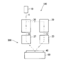
- FIG. 1 is a side block diagram illustrating an example of a schematic configuration of a hologram recording apparatus 100 according to the embodiment.
- 2 to 4 are schematic side views showing how the signal light 12 and the reference light 14 are incident on the recording medium from the optical module 300 according to the embodiment. 2 shows Examples 1 to 4 and 7 to be described later of the lens configuration of the optical module 300,
- FIG. 3 shows Example 5, and
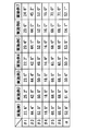
- FIG. 5 is a diagram showing various characteristics of Examples 1 to 7 in a table format.
- the hologram recording apparatus 100 includes a light source 10 that emits coherent light 1, a signal light optical system 20, a signal light lens 23, a reference light optical system 30, a reference light lens 27, and a holding unit that holds a recording medium 40. 50 is mainly provided.
- the hologram recording apparatus 100 records the hologram by irradiating the recording medium 40 with the reference light 14 while condensing the signal light 12, and receiving the reproduction light by irradiating the recording medium 40 with the reference light 14 during reproduction. And reproduce the hologram.
- the recording medium 40 includes a recording layer capable of recording a hologram and is held by a holding unit 50.
- the signal light lens 23, the reference light lens 27, and the holding unit 50 are the hologram recording optical module 300.
- the side view refers to the optical axis 91 of the signal light lens 23 and the normal line (main normal line) 92 of the surface at the intersection 81 between the optical axis 91 and the surface of the recording medium 40. It is a direction view orthogonal to both.
- the vertical direction is the direction of the normal line 92, and the signal light lens 23 and reference light lens 27 side is on the upper side, and the recording medium 40 side is on the lower side.
- the coherent light 1 emitted from the light source 10 is converted into a parallel light beam by an optical system (not shown), and enters a polarization beam splitter (not shown) included in the reference light optical system 30.
- the coherent light 1 is divided into two parallel light bundles by the polarizing beam splitter.
- One parallel light beam is guided to the signal light optical system 20.
- the other parallel light beam is guided as reference light 14 from the reference light optical system 30 to the reference light lens 27 and irradiated from the reference light lens 27 to the recording medium 40.
- the light bundle is also referred to as a light beam as appropriate.
- a spatial light modulator (SLM: Spatial Light Modulator) included in the signal light optical system 20 spatially converts the parallel light flux of the coherent light 1 guided to the signal light optical system 20 according to the page data to be recorded. To generate the signal light 12.
- the signal light 12 enters the signal light lens 23 as a spatially modulated parallel light beam.
- the signal light lens 23 includes a lens system (“first lens system”) 22 including a plurality of lenses, and a lens barrel 21 that holds the lens system 22.
- the lens system 22 has an optical axis (“first optical axis”) 91 that is inclined with respect to the surface of the recording medium 40.
- the signal light lens 23 condenses on the recording layer of the recording medium 40 the signal light 12 that is generated in advance from the coherent light 1 by the signal light optical system 20 and enters the lens system 22 as a parallel light bundle.
- the reference light optical system 30 generates the other parallel light bundle of the coherent light 1 divided into two by the polarization beam splitter as the reference light 14 and enters a part of the reference light lens 27.
- the reference light 14 is positioned corresponding to each data page on the lens surface of the second lens system 26 of the reference light lens 27 by a scanning unit (not shown) such as a galvanometer mirror provided in the reference light optical system 30. Scanned.
- the reference light lens 27 includes a lens system (“second lens system”) 26 including a plurality of lenses and a lens barrel 29 that holds the lens system 26.
- the lens system 26 has an optical axis (“second optical axis”) 96 that is inclined with respect to the surface of the recording medium 40.
- the reference light lens 27 is provided on the same side as the signal light lens 23 with respect to the surface of the recording medium 40.
- the reference light lens 27 is generated in advance from the coherent light 1 by the reference light optical system 30 and enters the lens system 26 according to the position of the reference light 14 scanned on the lens surface of the lens system 26. It deflects and irradiates the portion of the recording medium 40 where the signal light 12 is collected. Thereby, the signal light 12 and the reference light 14 interfere with each other in the recording layer of the recording medium 40 and are recorded as a hologram corresponding to the page data.
- the polarization state of the polarizing beam splitter is changed, and the coherent light 1 is not guided to the signal light optical system 20 side. Accordingly, the signal light optical system 20 and the signal light lens 23 do not irradiate the signal light 12, and only the reference light optical system 30 and the reference light lens 27 irradiate the recording medium 40 with the reference light.
- Information recorded on the recording medium 40 is reproduced from the recording medium 40 by irradiation of the reference light, and the signal light 12 at the time of recording is reproduced as reproduction light and guided to an imaging element (not shown) provided in the signal light optical system 20. Is read out.
- the signal light 12 that has entered the lens system 22 of the signal light lens 23 as a parallel beam is an intersection 81 portion between the surface of the recording medium 40 and the optical axis 91 of the lens system 22 (more precisely, the recording medium of the lens system 22).
- the focal point on the 40 side is focused on the portion of the recording medium 40 that has entered the recording layer.
- the light bundle S1 is a light bundle incident on the surface of the recording medium 40 at the largest incident angle among the most off-axis light bundles of the respective light bundles.
- the light beam S3 is the most off-axis light beam that passes through an optical path symmetrical to the light beam S1 with respect to the optical axis 91.
- the light beam S2 is an axial light beam.
- the optical path closer to the recording medium 40 than the lens system 22 of the light bundles S1 and S3 is defined by the numerical aperture NA of the lens system 22 on the recording medium 40 side.
- reference lights 14a to 14c when the reference light 14 is scanned at three different positions on the lens surface are shown.
- the reference light 14a is the reference light 14 that passes through the portion closest to the surface of the recording medium 40 in the outermost periphery of the effective aperture of the lens system 26 in a side view.
- the reference light 14b is the reference light 14 that passes on the optical axis 96 of the lens system 26 in a side view.
- the reference light 14c is the reference light 14 that passes through a portion of the outermost periphery of the effective aperture of the lens system 26 that is farthest from the surface of the recording medium 40 in a side view.
- the reference light 14c is also referred to as a standard reference light.
- the optical paths of the reference beams 14a and 14c are defined by the numerical aperture on the recording medium 40 side of the lens system 26.
- the angle ⁇ 1 is an angle formed between the normal 92 and the optical axis 91 of the lens system 22 of the signal light lens 23.
- the angle ⁇ 2 is an angle formed by the optical axis 91 and the light bundle S1 (S3), and is a convergence angle of the signal light 12 defined by the numerical aperture NA of the lens system 22 on the recording medium 40 side.
- the angle formed by the light incident on the outermost periphery of the effective aperture among the light incident parallel to the optical axis of the lens and the optical axis after passing through the lens is also referred to as “convergence angle (convergence angle)”.
- the angle ⁇ 3 is an angle formed between the normal 92 and the optical axis 96 of the lens system 26 of the reference light lens 27.
- the angle ⁇ 4 is an angle formed by the optical axis 96 of the reference light 14 (that is, reference light 14a, 14c) that has passed through the outermost periphery of the effective aperture of the lens system 26 of the reference light lens 27, and the recording medium 40 of the lens system 26. It is defined by the numerical aperture on the side.
- the angle ⁇ 5 is an incident angle of the light beam S1 to the recording medium 40, and is a maximum incident angle of the signal light 12 to the recording medium 40.
- the angle ⁇ 6 is an incident angle of the reference light 14a to the recording medium 40, and is a maximum incident angle of the reference light 14 to the recording medium 40.
- the distance H (L) of the signal light lens 23 is the surface vertex on the recording medium 40 side of the lens closest to the recording medium 40 included in the lens system 22 (26) (also referred to as “recording medium side surface vertex”). ) A distance along the optical axis 91 (96) from the surface 25 (28) to the surface of the recording medium 40 (also referred to as “distance on the optical axis”). The distance H is shorter than the distance L.
- the angles ⁇ 1 to ⁇ 4 satisfy the formula (1). That is, the signal light lens 23 is provided on the side opposite to the second optical axis of the reference light lens 27 with respect to the standard reference light 14c in a side view. Further, the angle ⁇ is equal to or larger than the angle ⁇ 2.
- the numerical aperture NA on the recording medium 40 side of the lens system 22 of the signal light lens 23 is preferably set larger than the numerical aperture on the recording medium 40 side of the lens system 26 of the reference light lens 27.
- the angles ⁇ 5 and ⁇ 6 preferably satisfy the expression (2). That is, the signal light lens 23 and the reference light are set so that the maximum incident angle of the signal light 12 to the recording medium 40 and the maximum incident angle of the reference light 14 to the recording medium 40 are preferably 70 degrees or less, respectively.
- the lens 27 is positioned with respect to the holding unit 50.
- the angle ⁇ 4 formed by the reference light 14 passing through the peripheral portion of the effective aperture of the lens system 26 of the reference light lens 27 and the optical axis 96 is set to 18 degrees or less, and the recording of the lens system 22 of the signal light lens 23 is performed.
- the numerical aperture NA on the medium 40 side is set to 0.71 or less.
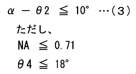
- the angle ⁇ and the angle ⁇ 2 preferably satisfy the expression (3). That is, the difference between the angle ⁇ and the angle ⁇ 2 is preferably set to 10 degrees or less.
- the angle ⁇ is an angle formed by a straight line connecting the intersection point 81 with a portion (also referred to as an “edge portion”) 24 of the signal light lens 23 that is closest to the reference reference light 14 c and the optical axis 91.
- angles ⁇ 1, ⁇ 3, ⁇ 4, and ⁇ preferably satisfy the formula (4). Further, the angles ⁇ 1, ⁇ 3, ⁇ 4, and ⁇ preferably satisfy the expression (5). In addition, the angles ⁇ 1, ⁇ 3, ⁇ 4, and ⁇ more preferably satisfy Expression (6). That is, the angle formed between the straight line connecting the portion 24 of the signal light lens 23 closest to the standard reference light 14c and the intersection 81 and the standard reference light 14c (more precisely, the principal ray of the standard reference light 14c) is Preferably it is set to 2 degrees or more. The angle is preferably set to 8 degrees or less. More preferably, the angle is set to 2 degrees or more and 8 degrees or less.
- the numerical apertures NA of Examples 1 to 7 of the signal light lens 23 and the reference light lens 27 of the optical module 300 according to this embodiment are 0.7, 0,. 68, 0.7, 0.68, 0.7, 0.7, 0.71.
- the lens system 22 of the signal light lens 23 protrudes from the end surface of the barrel 21 on the recording medium 40 side to the recording medium 40 side. Further, the portion 24 of the signal light lens 23 that is closest to the reference light 14 c is a part of the lens closest to the recording medium 40 included in the lens system 22. In the fifth embodiment, the lens system 22 protrudes to the recording medium 40 side from the end surface of the lens barrel 21 on the recording medium 40 side, but the portion 24 of the signal light lens 23 that is closest to the reference light 14c is a mirror. This is a part of the end of the cylinder 21 closest to the recording medium 40.
- the lens system 22 is accommodated in the internal space of the lens barrel 21 and does not protrude from the lens barrel 21.
- the portion 24 of the signal light lens 23 closest to the reference light 14c is a part of the end portion of the lens barrel 21 closest to the recording medium 40.
- the distance H of the signal light lens 23 with respect to the lens system 22 is shorter than the distance L of the reference light lens 27 with respect to the lens system 26.
- the distances H in Examples 1 to 4 and 7 are set to 10.45 mm, 10.78 mm, 13.45 mm, 11.45 mm, and 11.45 mm, respectively.
- the numerical aperture on the recording medium 40 side of the signal light lens 23 can be further increased.
- the surface vertex on the recording medium 40 side of the lens included in the holding unit 50 and the lens system 22 on the most recording medium 40 side is an optical axis 96 from the surface vertex 28 on the recording medium 40 side of the lens included in the lens system 26 to the surface of the recording medium 40. Shorter than the distance L along.
- the signal light lens 23 is provided on the side opposite to the optical axis 96 with respect to the reference light 14c.
- the signal light lens 23 can be reduced in size while maintaining the numerical aperture on the recording medium 40 side of the signal light lens 23 by bringing the signal light lens 23 closer to the recording medium 40 side without causing mechanical interference with the reference light 14. I can do it. Therefore, the optical module 300 and the hologram recording apparatus 100 including the optical module 300 can be reduced in size while suppressing a decrease in recording density.
- the numerical aperture on the recording medium 40 side of the lens system 22 of the signal light lens 23 is larger than the numerical aperture on the recording medium 40 side of the lens system 26 of the reference light lens 27. Since it is large, the numerical aperture of the signal light lens 23 on the recording medium 40 side can be increased while suppressing the increase in size of the optical module 300. Thereby, the recording density can be further increased.
- the signal light lens 23 and the reference light lens 27 have the maximum incident angles ⁇ 5 and ⁇ 6 of the signal light 12 and the reference light 14 with respect to the recording medium 40, respectively. It is positioned with respect to the holding part 50 so as to be 70 degrees or less. Therefore, reflection of the signal light 12 and the reference light 14 on the surface of the recording medium 40 can be suppressed, and the recording efficiency can be improved.
- the straight line connecting the portion 24 of the signal light lens 23 closest to the reference light 14c and the intersection 81 between the optical axis 91 and the surface of the recording medium 40 is the optical axis 91.
- the convergence angle ⁇ 2 of the signal light 12 defined by the numerical aperture NA on the recording medium 40 side of the lens system 22 is 10 degrees or less. Therefore, the signal light lens 23 can be further downsized.
- the angle formed by 14c is 2 degrees or more. Therefore, mechanical interference between the reference light 14 and the signal light lens 23 due to an attachment error or the like can be suppressed.
- the angle formed between the straight line connecting the portion 24 of the signal light lens 23 and the intersection 81 and the reference light 14c is 8 degrees or less. Therefore, since the signal light lens 23 can be brought closer to the reference light lens 27, the optical module 300 can be further downsized.
- Optical module 1 Coherent light 10
- Light source 12 Signal light 14, 14a, 14b Reference light 14c Reference light (standard reference light) 20
- signal light optical system 30 reference light optical system 23 signal light lens 22 lens system (first lens system) 27 Reference light lens 26
- Recording medium 50 Holding portion 91 Optical axis (first optical axis) 92 Normal 96 Optical axis (second optical axis) S1-S3 Ray bundle
Landscapes
- Physics & Mathematics (AREA)
- Optics & Photonics (AREA)
- Optical Head (AREA)
- Optical Recording Or Reproduction (AREA)
- Holo Graphy (AREA)
Abstract
ホログラムの記録密度の低下を抑制しつつ、装置を小型化することを図る。該目的を達成するために、ホログラム記録用の光学モジュールは、記録媒体を保持する保持部と、第1レンズ系と、第1レンズ系を保持する鏡筒とを備え、第1レンズ系に入射する信号光を記録媒体に集光する信号光レンズと、第2レンズ系と、第2レンズ系を保持する鏡筒とを備え、第2レンズ系に入射する参照光を記録媒体のうち信号光が集光される部分に照射する参照光レンズとを備える。そして、第1レンズ系が含む最も記録媒体側のレンズの記録媒体側面頂点から記録媒体表面までの第1光軸に沿った距離が、第2レンズ系が含む最も記録媒体側のレンズの記録媒体側面頂点から記録媒体表面までの第2光軸に沿った距離よりも短く、信号光レンズは、基準参照光に対して第2光軸と反対側に設けられている。
Description
本発明は、ホログラフィを利用して記録媒体に情報を記録するホログラム記録技術に関する。
近年、ホログラフィを利用したストレージデバイスの開発が進められている。ホログラフィを利用したストレージデバイスでは、従来の磁気記録式のデバイスより高い記録密度が得られるため次世代ストレージデバイスの有力な候補となっている。
ホログラフィを利用したストレージデバイスに光情報を記録再生可能な記録再生装置として、特許文献1には、信号光と参照光とを別々の光学系で記録媒体に照射し、記録媒体において信号光と参照光とを干渉させて光情報を記録する装置が開示されている。この装置では、参照光との機械的干渉をさけるために信号光レンズと参照光レンズとのそれぞれの光軸が、記録媒体に対し垂直ではなく傾けて設定されている。そして、この装置は、記録媒体への参照光の入射角度を変化させて信号光と参照光との相対角度を変化させることにより記録媒体の同一部分に複数のページデータを記録する、いわゆる角度多重記録によって、記録密度の増大を図っている。
しかしながら、特許文献1の装置には、各レンズの互いの機械的な干渉や、一方のレンズが照射する光線束への他方のレンズの機械的な干渉を避けるために、各レンズおよび記録媒体を保持する部品の相互の間隔が広く設定されている。このため、装置が大きくなるといった問題がある。
本発明は、こうした問題を解決するためになされたもので、記録媒体に対して互いに光軸が傾いた各光学系で信号光と参照光とを記録媒体に照射してホログラムを記録する技術において、記録密度の低下を抑制しつつ、装置を小型化できる技術を提供することを目的とする。
上記の課題を解決するために、第1の態様に係るホログラム記録用の光学モジュールは、ホログラムを記録可能な記録媒体を保持する保持部と、前記記録媒体の表面に対して傾いた第1光軸を有する第1レンズ系と、前記第1レンズ系を保持する鏡筒とを備え、予めコヒーレント光から生成されて前記第1レンズ系に入射する信号光を前記記録媒体に集光する信号光レンズと、前記記録媒体の表面に対して傾いた第2光軸を有する第2レンズ系と、前記第2レンズ系を保持する鏡筒とを備えて前記表面に対して前記信号光レンズと同じ側に設けられ、予め前記コヒーレント光から生成されて前記第2レンズ系に入射する参照光を前記記録媒体のうち前記信号光が集光される部分に照射する参照光レンズと、を備え、前記第1レンズ系が含む最も前記記録媒体側のレンズの前記記録媒体側面頂点から前記記録媒体表面までの前記第1光軸に沿った距離が、前記第2レンズ系が含む最も前記記録媒体側のレンズの前記記録媒体側面頂点から前記記録媒体表面までの前記第2光軸に沿った距離よりも短く、前記第1光軸と前記記録媒体の表面との交点における当該表面の法線と前記第1光軸との双方に直交する方向視によって側面視を定義し、側面視において、前記第2レンズ系の有効口径の最周辺のうち前記記録媒体表面から最も離れた部分を通過する前記参照光によって基準参照光を定義したとき、前記信号光レンズは、側面視において、前記基準参照光に対して前記第2光軸と反対側に設けられている。
第2の態様に係るホログラム記録用の光学モジュールは、第1の態様に係るホログラム記録用の光学モジュールであって、前記信号光レンズの前記第1レンズ系の前記記録媒体側の開口数が、前記参照光レンズの前記第2レンズ系の前記記録媒体側の開口数よりも大きい。
第3の態様に係るホログラム記録用の光学モジュールは、第1または第2の態様に係るホログラム記録用の光学モジュールであって、前記信号光レンズと前記参照光レンズとは、前記信号光と前記参照光とのそれぞれの前記記録媒体への最大入射角がそれぞれ70度以下となるように前記保持部に対して位置決めされている。
第4の態様に係るホログラム記録用の光学モジュールは、第1から第3の何れか1つの態様に係るホログラム記録用の光学モジュールであって、前記第1レンズ系の前記記録媒体側の開口数が0.71以下であり、側面視において、前記第2レンズ系の有効口径の最周辺を通過した前記参照光が前記第2光軸となす角度が18度以下であり、前記信号光レンズのうち前記基準参照光に最も近い部分と前記交点とを結ぶ直線が前記第1光軸となす角度と、前記第1レンズ系の前記記録媒体側の開口数によって規定される前記信号光の収束角との差が、10度以下である。
第5の態様に係るホログラム記録用の光学モジュールは、第1から第4の何れか1つの態様に係るホログラム記録用の光学モジュールであって、側面視において、前記信号光レンズのうち前記基準参照光に最も近い部分と前記交点とを結ぶ直線と、前記参照光レンズを通過後の前記基準参照光とがなす角度が2度以上である。
第6の態様に係るホログラム記録用の光学モジュールは、第1から第5の何れか1つの態様に係るホログラム記録用の光学モジュールであって、側面視において、前記信号光レンズのうち前記基準参照光に最も近い部分と前記交点とを結ぶ直線と、前記参照光レンズを通過後の前記基準参照光とがなす角度が8度以下である。
第7の態様に係るホログラム記録装置は、第1から第6の何れか1つの態様に係るホログラム記録用の光学モジュールと、前記コヒーレント光を射出する光源と、前記コヒーレント光から前記信号光を生成して前記信号光レンズの前記第1レンズに導く信号光光学系と、前記コヒーレント光から前記参照光を生成して前記参照光レンズの前記第2レンズに導く参照光光学系と、を備え、前記第1レンズを通過した前記信号光と、前記第2レンズを通過した前記参照光とを前記記録媒体において干渉させることによりホログラムを記録する。
第1から第7の何れの態様に係る発明によっても、記録媒体を保持する保持部と、第1レンズ系が含む最も記録媒体側のレンズの記録媒体側面頂点から記録媒体表面までの第1光軸に沿った距離が、第2レンズ系が含む最も記録媒体側のレンズの記録媒体側面頂点から記録媒体表面までの第2光軸に沿った距離よりも短い。そして、信号光レンズは、基準参照光に対して第2光軸と反対側に設けられている。従って、信号光レンズが参照光と機械的に干渉することなく記録媒体側に近づくことにより、信号光レンズの記録媒体40側の開口数を維持しつつ信号光レンズを小型化出来る。従って、記録密度の低下を抑制しつつ、光学モジュールおよび光学モジュールを備えたホログラム記録装置を小型化することができる。
以下、本発明の一実施形態を図面に基づいて説明する。図面では同様な構成および機能を有する部分に同じ符号が付され、下記説明では重複説明が省略される。
<実施形態>
<ホログラム記録装置の構成>
図1は、実施形態に係るホログラム記録装置100の概略構成の一例を示す側面ブロック図である。図2~図4は、実施形態に係る光学モジュール300から信号光12と参照光14とが記録媒体へ入射する様子を示す側面模式図である。また、図2は、光学モジュール300のレンズ構成の後述する実施例1~4、7を示し、図3は、実施例5を示し、図4は、実施例6を示している。図5は、実施例1~7の諸特性を表形式で示す図である。
<ホログラム記録装置の構成>
図1は、実施形態に係るホログラム記録装置100の概略構成の一例を示す側面ブロック図である。図2~図4は、実施形態に係る光学モジュール300から信号光12と参照光14とが記録媒体へ入射する様子を示す側面模式図である。また、図2は、光学モジュール300のレンズ構成の後述する実施例1~4、7を示し、図3は、実施例5を示し、図4は、実施例6を示している。図5は、実施例1~7の諸特性を表形式で示す図である。
ホログラム記録装置100は、コヒーレント光1を射出する光源10と、信号光光学系20と、信号光レンズ23と、参照光光学系30と、参照光レンズ27と、記録媒体40を保持する保持部50とを主に備えて構成されている。ホログラム記録装置100は、記録媒体40に対して信号光12を集光させながら参照光14を照射してホログラムを記録するとともに、再生時には参照光14を記録媒体40に照射して再生光を受光し、ホログラムを再生する。記録媒体40は、ホログラムを記録可能な記録層を備えて構成されており、保持部50によって保持されている。なお、信号光レンズ23と参照光レンズ27と保持部50とは、ホログラム記録用の光学モジュール300である。
ここで、本実施形態に説明において、側面視とは、信号光レンズ23の光軸91と、光軸91と記録媒体40の表面との交点81における当該表面の法線(主法線)92との双方に直交する方向視である。また、上下方向は、法線92の方向であり、信号光レンズ23、参照光レンズ27側が上で、記録媒体40側が下である。
光源10から射出されたコヒーレント光1は、図示省略の光学系により平行光線束に変換されて、参照光光学系30が備える図示省略の偏光ビームスプリッタに入射する。記録時には、コヒーレント光1は、上記偏光ビームスプリッタにより2つの平行光線束に分けられる。一方の平行光線束は、信号光光学系20に導かれる。他方の平行光線束は、参照光14として参照光光学系30から参照光レンズ27に導かれ、参照光レンズ27から記録媒体40へ照射される。なお、光線束は、適宜、光束とも称される。
信号光光学系20が備える図示省略の空間光変調素子(SLM:Spatial Light Modulator)は、信号光光学系20に導かれたコヒーレント光1の平行光線束を記録対象のページデータに応じて空間的に変調して信号光12を生成する。信号光12は、空間変調された平行光線束として信号光レンズ23に入射する。
信号光レンズ23は、複数のレンズを備えるレンズ系(「第1レンズ系」)22と、レンズ系22を保持する鏡筒21とを備えている。レンズ系22は、記録媒体40の表面に対して傾いた光軸(「第1光軸」)91を有している。信号光レンズ23は、信号光光学系20によってコヒーレント光1から予め生成されて、平行光線束としてレンズ系22に入射する信号光12を記録媒体40の記録層に集光する。
参照光光学系30は、上記偏光ビームスプリッタにより2つに分けたコヒーレント光1の他方の平行光線束を参照光14として生成し参照光レンズ27の一部に入射する。この際、参照光14は、参照光光学系30に設けられたガルバノミラー等の図示省略の走査部によって、参照光レンズ27の第2レンズ系26のレンズ面において、各データページに対応した位置に走査される。
参照光レンズ27は、複数のレンズを備えるレンズ系(「第2レンズ系」)26と、レンズ系26を保持する鏡筒29とを備えている。レンズ系26は、記録媒体40の表面に対して傾いた光軸(「第2光軸」)96を有している。また、参照光レンズ27は、記録媒体40の表面に対して信号光レンズ23と同じ側に設けられている。参照光レンズ27は、参照光光学系30によってコヒーレント光1から予め生成されてレンズ系26に入射する参照光14を、レンズ系26のレンズ面上で走査される参照光14の位置に応じて偏向し、記録媒体40のうち信号光12が集光される部分に照射する。これにより、信号光12と参照光14とは、記録媒体40の記録層において干渉し、ページデータに対応したホログラムとして記録される。
再生時には、上記偏光ビームスプリッタの偏光状態が変更され、コヒーレント光1は、信号光光学系20側に導かれない。これにより、信号光光学系20、信号光レンズ23は信号光12を照射せず、参照光光学系30、参照光レンズ27のみが参照光を記録媒体40に照射する。参照光の照射により記録媒体40からは、記録時の信号光12が再生光として再生されて信号光光学系20に設けられた図示省略の撮像素子に導かれ、記録媒体40に記録された情報の読出しが行われる。
<光学モジュールについて>
次に、図2を参照して、光学モジュール300について説明する。信号光レンズ23のレンズ系22に平行光線束として入射した信号光12は、記録媒体40の表面とレンズ系22の光軸91との交点81部分(より正確には、レンズ系22の記録媒体40側の焦点が、記録媒体40の記録層に入り込んだ部分)に集光される。
次に、図2を参照して、光学モジュール300について説明する。信号光レンズ23のレンズ系22に平行光線束として入射した信号光12は、記録媒体40の表面とレンズ系22の光軸91との交点81部分(より正確には、レンズ系22の記録媒体40側の焦点が、記録媒体40の記録層に入り込んだ部分)に集光される。
平行光線束としてレンズ系22に入射した信号光12が含む各光線束のうち光線束S1~S3が例示されている。光線束S1は、当該各光線束の最軸外光線束のうち最も大きな入射角で記録媒体40表面に入射する光線束である。光線束S3は、光軸91に対して光線束S1に対称な光路を通る最軸外光線束である。また、光線束S2は、軸上光線束である。光線束S1、S3のレンズ系22よりも記録媒体40側の光路は、レンズ系22の記録媒体40側の開口数NAによって規定されている。
参照光レンズ27のレンズ系26に入射した参照光14の例として、参照光14がレンズ面の互い異なる3つの位置に走査されたときの参照光14a~14cが示されている。参照光14aは、側面視において、レンズ系26の有効口径の最周辺のうち記録媒体40の表面から最も近い部分を通過する参照光14である。参照光14bは、側面視において、レンズ系26の光軸96上を通過する参照光14である。参照光14cは、側面視において、レンズ系26の有効口径の最周辺のうち記録媒体40の表面から最も離れた部分を通過する参照光14である。参照光14cは、基準参照光とも称される。参照光14a、14cの光路は、レンズ系26の記録媒体40側の開口数によって規定されている。
角度θ1は、法線92と信号光レンズ23のレンズ系22の光軸91とがなす角度である。角度θ2は、光軸91と光線束S1(S3)とがなす角度であり、レンズ系22の記録媒体40側の開口数NAによって規定される信号光12の収束角である。なお、レンズの光軸に平行に入射した光線のうち有効口径の最周辺に入射した光線がレンズを通過後に光軸となす角度を便宜上、「収束角(収束角度)」とも称する。角度θ3は、法線92と参照光レンズ27のレンズ系26の光軸96とがなす角度である。角度θ4は、参照光レンズ27のレンズ系26の有効口径の最周辺を通過した参照光14(すなわち、参照光14a、14c)が光軸96となす角度であり、レンズ系26の記録媒体40側の開口数により規定される。角度θ5は、光線束S1の記録媒体40への入射角であり、信号光12の記録媒体40への最大入射角である。角度θ6は、参照光14aの記録媒体40への入射角であり、参照光14の記録媒体40への最大入射角である。
信号光レンズ23(参照光レンズ27)の距離H(L)は、レンズ系22(26)が含む最も記録媒体40側のレンズの記録媒体40側の面頂点(「記録媒体側面頂点」とも称する)25(28)から記録媒体40表面までの光軸91(96)に沿った距離(「光軸上距離」とも称する)である。そして、距離Hは、距離Lよりも短い。
角度θ1~θ4は、式(1)を満足している。すなわち、信号光レンズ23は、側面視において、基準参照光14cに対して参照光レンズ27の第2光軸と反対側に設けられている。また、角度αは、角度θ2以上である。

信号光レンズ23のレンズ系22の記録媒体40側の開口数NAは、好ましくは、参照光レンズ27のレンズ系26の記録媒体40側の開口数よりも大きく設定される。
角度θ5、θ6は、好ましくは、式(2)を満足する。すなわち、信号光12の記録媒体40への最大入射角と、参照光14の記録媒体40への最大入射角とが、好ましくは、それぞれ70度以下となるように、信号光レンズ23と参照光レンズ27とが保持部50に対してそれぞれ位置決めされる。

好ましくは、参照光レンズ27のレンズ系26の有効口径の周辺部を通過した参照光14が光軸96となす角度θ4は、18度以下に設定され、信号光レンズ23のレンズ系22の記録媒体40側の開口数NAは、0.71以下に設定される。
この場合において、角度αと角度θ2とは、好ましくは、式(3)を満足する。すなわち、角度αと角度θ2との差は、好ましくは10度以下に設定される。なお、角度αは、信号光レンズ23のうち基準参照光14cに最も近い部分(「エッジ部」とも称する)24と交点81とを結ぶ直線が光軸91となす角度である。
角度θ1、θ3、θ4、αは、好ましくは、式(4)を満足する。また、角度θ1、θ3、θ4、αは、好ましくは、式(5)を満足する。また、角度θ1、θ3、θ4、αは、より好ましくは、式(6)を満足する。すなわち、信号光レンズ23のうち基準参照光14cに最も近い部分24と交点81とを結ぶ直線と、基準参照光14c(より正確には、基準参照光14cの主光線)とがなす角度は、好ましくは2度以上に設定される。また、当該角度は、好ましくは、8度以下に設定される。また、より好ましくは、当該角度は、2度以上、かつ、8度以下に設定される。


図2~図5に示されるように、本実施形態に係る光学モジュール300の信号光レンズ23および参照光レンズ27の実施例1~実施例7の開口数NAは、それぞれ0.7、0.68、0.7、0.68、0.7、0.7、0.71に設定されている。
実施例1~4、7においては、信号光レンズ23のレンズ系22は、鏡筒21の記録媒体40側の端面よりも記録媒体40側に飛び出している。また、信号光レンズ23のうち参照光14cに最も近い部分24は、レンズ系22が含む最も記録媒体40側のレンズの一部である。実施例5においては、レンズ系22は、鏡筒21の記録媒体40側の端面よりも記録媒体40側に飛び出しているが、信号光レンズ23のうち参照光14cに最も近い部分24は、鏡筒21の最も記録媒体40側の端部の一部である。また、実施例6においては、レンズ系22は鏡筒21の内部空間に収容されており、鏡筒21から飛び出していない。また、信号光レンズ23のうち参照光14cに最も近い部分24は、鏡筒21の最も記録媒体40側の端部の一部である。
実施例1~7の何れにおいても、信号光レンズ23のレンズ系22についての距離Hは参照光レンズ27のレンズ系26についての距離Lよりも短い。なお、実施例1~4、7における距離Hは、それぞれ10.45mm、10.78mm、13.45mm、11.45mm、11.45mmに設定されている。これにより、光学モジュール300においては、信号光レンズ23の記録媒体40側の開口数をより大きくすることができる。
以上のように構成された本実施形態に係る光学モジュール300およびホログラム記録装置100の何れによっても、保持部50と、レンズ系22が含む最も記録媒体40側のレンズの記録媒体40側の面頂点25から記録媒体40表面までの光軸91に沿った距離Hが、レンズ系26が含む最も記録媒体40側のレンズの記録媒体40側の面頂点28から記録媒体40表面までの光軸96に沿った距離Lよりも短い。そして、信号光レンズ23は、参照光14cに対して光軸96と反対側に設けられている。従って、信号光レンズ23を参照光14と機械的に干渉させることなく記録媒体40側に近づけることにより、信号光レンズ23の記録媒体40側の開口数を維持しつつ信号光レンズ23を小型化出来る。従って、記録密度の低下を抑制しつつ、光学モジュール300および光学モジュール300を備えたホログラム記録装置100を小型化することができる。
また、本実施形態に係る光学モジュール300によれば、信号光レンズ23のレンズ系22の記録媒体40側の開口数が、参照光レンズ27のレンズ系26の記録媒体40側の開口数よりも大きいので、光学モジュール300の大形化を抑制しつつ、信号光レンズ23の記録媒体40側の開口数を上げることが出来る。これにより、記録密度をさらに上げることができる。
また、本実施形態に係る光学モジュール300によれば、信号光レンズ23と参照光レンズ27とは、信号光12と参照光14とのそれぞれの記録媒体40への最大入射角θ5、θ6がそれぞれ70度以下となるように保持部50に対して位置決めされている。従って、信号光12および参照光14の記録媒体40表面での反射を抑制し、記録効率を向上させることができる。
また、本実施形態に係る光学モジュール300によれば、信号光レンズ23のうち参照光14cに最も近い部分24と、光軸91と記録媒体40表面との交点81とを結ぶ直線が光軸91となす角度αと、レンズ系22の記録媒体40側の開口数NAによって規定される信号光12の収束角θ2との差が、10度以下である。従って、信号光レンズ23をより小型化できる。
また、本実施形態に係る光学モジュール300によれば、信号光レンズ23のうち参照光14cに最も近い部分24と、光軸91と記録媒体40表面との交点81とを結ぶ直線と、参照光14cとがなす角度が2度以上である。従って、取付誤差等による参照光14と信号光レンズ23の機械的な干渉を抑制できる。
また、本実施形態に係る光学モジュール300によれば、信号光レンズ23の部分24と交点81とを結ぶ直線と、参照光14cとがなす角度が8度以下である。従って、信号光レンズ23を参照光レンズ27により近づけることができるので、光学モジュール300をさらに小型化できる。
100 ホログラム記録装置
300 光学モジュール
1 コヒーレント光
10 光源
12 信号光
14,14a,14b 参照光
14c 参照光(基準参照光)
20 信号光光学系
30 参照光光学系
23 信号光レンズ
22 レンズ系(第1レンズ系)
27 参照光レンズ
26 レンズ系(第2レンズ系)
40 記録媒体
50 保持部
91 光軸(第1光軸)
92 法線
96 光軸(第2光軸)
S1~S3 光線束
300 光学モジュール
1 コヒーレント光
10 光源
12 信号光
14,14a,14b 参照光
14c 参照光(基準参照光)
20 信号光光学系
30 参照光光学系
23 信号光レンズ
22 レンズ系(第1レンズ系)
27 参照光レンズ
26 レンズ系(第2レンズ系)
40 記録媒体
50 保持部
91 光軸(第1光軸)
92 法線
96 光軸(第2光軸)
S1~S3 光線束
Claims (7)
- ホログラムを記録可能な記録媒体を保持する保持部と、
前記記録媒体の表面に対して傾いた第1光軸を有する第1レンズ系と、前記第1レンズ系を保持する鏡筒とを備え、予めコヒーレント光から生成されて前記第1レンズ系に入射する信号光を前記記録媒体に集光する信号光レンズと、
前記記録媒体の表面に対して傾いた第2光軸を有する第2レンズ系と、前記第2レンズ系を保持する鏡筒とを備えて前記表面に対して前記信号光レンズと同じ側に設けられ、予め前記コヒーレント光から生成されて前記第2レンズ系に入射する参照光を前記記録媒体のうち前記信号光が集光される部分に照射する参照光レンズと、
を備え、
前記第1レンズ系が含む最も前記記録媒体側のレンズの前記記録媒体側面頂点から前記記録媒体表面までの前記第1光軸に沿った距離が、前記第2レンズ系が含む最も前記記録媒体側のレンズの前記記録媒体側面頂点から前記記録媒体表面までの前記第2光軸に沿った距離よりも短く、
前記第1光軸と前記記録媒体の表面との交点における当該表面の法線と前記第1光軸との双方に直交する方向視によって側面視を定義し、
側面視において、前記第2レンズ系の有効口径の最周辺のうち前記記録媒体表面から最も離れた部分を通過する前記参照光によって基準参照光を定義したとき、
前記信号光レンズは、側面視において、前記基準参照光に対して前記第2光軸と反対側に設けられている、ホログラム記録用の光学モジュール。 - 請求項1に記載のホログラム記録用の光学モジュールであって、
前記信号光レンズの前記第1レンズ系の前記記録媒体側の開口数が、前記参照光レンズの前記第2レンズ系の前記記録媒体側の開口数よりも大きい、ホログラム記録用の光学モジュール。 - 請求項1または請求項2に記載のホログラム記録用の光学モジュールであって、
前記信号光レンズと前記参照光レンズとは、
前記信号光と前記参照光とのそれぞれの前記記録媒体への最大入射角がそれぞれ70度以下となるように前記保持部に対して位置決めされている、ホログラム記録用の光学モジュール。 - 請求項1から請求項3の何れか1つの請求項に記載のホログラム記録用の光学モジュールであって、
前記第1レンズ系の前記記録媒体側の開口数が0.71以下であり、
側面視において、
前記第2レンズ系の有効口径の最周辺を通過した前記参照光が前記第2光軸となす角度が18度以下であり、
前記信号光レンズのうち前記基準参照光に最も近い部分と前記交点とを結ぶ直線が前記第1光軸となす角度と、前記第1レンズ系の前記記録媒体側の開口数によって規定される前記信号光の収束角との差が、10度以下である、ホログラム記録用の光学モジュール。 - 請求項1から請求項4の何れか1つの請求項に記載のホログラム記録用の光学モジュールであって、
側面視において、前記信号光レンズのうち前記基準参照光に最も近い部分と前記交点とを結ぶ直線と、前記参照光レンズを通過後の前記基準参照光とがなす角度が2度以上である、ホログラム記録用の光学モジュール。 - 請求項1から請求項5の何れか1つの請求項に記載のホログラム記録用の光学モジュールであって、
側面視において、前記信号光レンズのうち前記基準参照光に最も近い部分と前記交点とを結ぶ直線と、前記参照光レンズを通過後の前記基準参照光とがなす角度が8度以下である、ホログラム記録用の光学モジュール。 - 請求項1から請求項6の何れか1つの請求項に記載のホログラム記録用の光学モジュールと、
前記コヒーレント光を射出する光源と、
前記コヒーレント光から前記信号光を生成して前記信号光レンズの前記第1レンズに導く信号光光学系と、
前記コヒーレント光から前記参照光を生成して前記参照光レンズの前記第2レンズに導く参照光光学系と、
を備え、
前記第1レンズを通過した前記信号光と、前記第2レンズを通過した前記参照光とを前記記録媒体において干渉させることによりホログラムを記録するホログラム記録装置。
Priority Applications (1)
| Application Number | Priority Date | Filing Date | Title |
|---|---|---|---|
| JP2015523942A JP6311712B2 (ja) | 2013-06-26 | 2014-06-02 | ホログラム記録用の光学モジュールおよびホログラム記録装置 |
Applications Claiming Priority (2)
| Application Number | Priority Date | Filing Date | Title |
|---|---|---|---|
| JP2013133427 | 2013-06-26 | ||
| JP2013-133427 | 2013-06-26 |
Publications (1)
| Publication Number | Publication Date |
|---|---|
| WO2014208283A1 true WO2014208283A1 (ja) | 2014-12-31 |
Family
ID=52141631
Family Applications (1)
| Application Number | Title | Priority Date | Filing Date |
|---|---|---|---|
| PCT/JP2014/064594 Ceased WO2014208283A1 (ja) | 2013-06-26 | 2014-06-02 | ホログラム記録用の光学モジュールおよびホログラム記録装置 |
Country Status (2)
| Country | Link |
|---|---|
| JP (1) | JP6311712B2 (ja) |
| WO (1) | WO2014208283A1 (ja) |
Citations (4)
| Publication number | Priority date | Publication date | Assignee | Title |
|---|---|---|---|---|
| JP2008197597A (ja) * | 2007-02-16 | 2008-08-28 | Fujifilm Corp | ホログラフィック記録媒体およびその製造方法 |
| JP2009294512A (ja) * | 2008-06-06 | 2009-12-17 | Sharp Corp | 情報記録装置、情報記録方法、情報再生装置、および情報再生方法 |
| JP2011253600A (ja) * | 2010-06-04 | 2011-12-15 | Hitachi Consumer Electronics Co Ltd | 光情報記録再生装置及び光情報記録再生方法 |
| JP2012069207A (ja) * | 2010-09-24 | 2012-04-05 | Hitachi Consumer Electronics Co Ltd | ホログラフィを用いたホログラフィックメモリ |
Family Cites Families (2)
| Publication number | Priority date | Publication date | Assignee | Title |
|---|---|---|---|---|
| JP2007041436A (ja) * | 2005-08-05 | 2007-02-15 | Fujitsu Ltd | ホログラム記録装置 |
| JP2011013531A (ja) * | 2009-07-03 | 2011-01-20 | Sharp Corp | 情報記録方法、2次元情報作成方法、情報再生方法および情報記録媒体 |
-
2014
- 2014-06-02 WO PCT/JP2014/064594 patent/WO2014208283A1/ja not_active Ceased
- 2014-06-02 JP JP2015523942A patent/JP6311712B2/ja active Active
Patent Citations (4)
| Publication number | Priority date | Publication date | Assignee | Title |
|---|---|---|---|---|
| JP2008197597A (ja) * | 2007-02-16 | 2008-08-28 | Fujifilm Corp | ホログラフィック記録媒体およびその製造方法 |
| JP2009294512A (ja) * | 2008-06-06 | 2009-12-17 | Sharp Corp | 情報記録装置、情報記録方法、情報再生装置、および情報再生方法 |
| JP2011253600A (ja) * | 2010-06-04 | 2011-12-15 | Hitachi Consumer Electronics Co Ltd | 光情報記録再生装置及び光情報記録再生方法 |
| JP2012069207A (ja) * | 2010-09-24 | 2012-04-05 | Hitachi Consumer Electronics Co Ltd | ホログラフィを用いたホログラフィックメモリ |
Non-Patent Citations (2)
| Title |
|---|
| HIDEYOSHI HORIMAI: "Collinear Hoshiki", THE JOURNAL OF THE INSTITUTE OF IMAGE INFORMATION AND TELEVISION ENGINEERS, vol. 61, no. 6, 2007, pages 735 - 737 * |
| TAKUO TANAKA: "Holographic Memory, Optical Memory and its Systems for Next Generation", 31 January 2009 (2009-01-31), pages 166 - 179 * |
Also Published As
| Publication number | Publication date |
|---|---|
| JP6311712B2 (ja) | 2018-04-18 |
| JPWO2014208283A1 (ja) | 2017-02-23 |
Similar Documents
| Publication | Publication Date | Title |
|---|---|---|
| US7684097B2 (en) | Recording apparatus and phase modulation device | |
| CN1681015A (zh) | 用于全息记录和读出数据的方法和装置 | |
| US20090153929A1 (en) | Apparatus for recording/reproducing holographic information | |
| JP2010020892A (ja) | ホログラフィック情報記録/再生装置及び方法 | |
| JP5816046B2 (ja) | 平行光源を使用したビット単位のホログラフィデータを平行に記憶する方法 | |
| JP2010040072A (ja) | 光ピックアップ装置および焦点調整方法 | |
| US8009542B2 (en) | Apparatus for recording/reproducing holographic data | |
| KR101416230B1 (ko) | 홀로그래픽 정보 기록/재생 장치, 기록/재생 방법 및홀로그래픽 정보 저장매체 | |
| US20120140606A1 (en) | Information storage device, information recording medium, and information storage method | |
| US20100265810A1 (en) | Optical pickup device and optical disc device | |
| JP5450649B2 (ja) | 情報格納装置 | |
| JP2010102784A (ja) | 光情報記録再生装置 | |
| JP4284209B2 (ja) | 再生装置、記録再生装置及び再生方法 | |
| JP6311712B2 (ja) | ホログラム記録用の光学モジュールおよびホログラム記録装置 | |
| US20070121469A1 (en) | Holographic optical pickup apparatus | |
| KR20110034541A (ko) | 광 픽업 장치 | |
| JP2010102785A (ja) | 光情報記録再生装置 | |
| US20080062486A1 (en) | Apparatus for retroreflecting reference beam and holographic information recording/reproducing device employing the same | |
| US8014256B2 (en) | Optical pickup and information device | |
| US7995257B2 (en) | Holographic storage medium, recording and/or reproducing apparatus, and recording and/or reproducing method | |
| CN212781684U (zh) | 一种全息投影记录系统 | |
| US9620164B2 (en) | Holographic data storage system | |
| JP2006154603A (ja) | ホログラム記録装置 | |
| JP5093243B2 (ja) | ホログラム記録用の対物レンズおよびホログラム記録装置 | |
| JP2010108565A (ja) | 光情報記録再生装置 |
Legal Events
| Date | Code | Title | Description |
|---|---|---|---|
| 121 | Ep: the epo has been informed by wipo that ep was designated in this application |
Ref document number: 14817165 Country of ref document: EP Kind code of ref document: A1 |
|
| ENP | Entry into the national phase |
Ref document number: 2015523942 Country of ref document: JP Kind code of ref document: A |
|
| NENP | Non-entry into the national phase |
Ref country code: DE |
|
| 122 | Ep: pct application non-entry in european phase |
Ref document number: 14817165 Country of ref document: EP Kind code of ref document: A1 |