WO2014208096A1 - Double-walled container - Google Patents
Double-walled container Download PDFInfo
- Publication number
- WO2014208096A1 WO2014208096A1 PCT/JP2014/003428 JP2014003428W WO2014208096A1 WO 2014208096 A1 WO2014208096 A1 WO 2014208096A1 JP 2014003428 W JP2014003428 W JP 2014003428W WO 2014208096 A1 WO2014208096 A1 WO 2014208096A1
- Authority
- WO
- WIPO (PCT)
- Prior art keywords
- layer body
- wall
- pouring
- outer layer
- double container
- Prior art date
Links
Images


Classifications
-
- B—PERFORMING OPERATIONS; TRANSPORTING
- B65—CONVEYING; PACKING; STORING; HANDLING THIN OR FILAMENTARY MATERIAL
- B65D—CONTAINERS FOR STORAGE OR TRANSPORT OF ARTICLES OR MATERIALS, e.g. BAGS, BARRELS, BOTTLES, BOXES, CANS, CARTONS, CRATES, DRUMS, JARS, TANKS, HOPPERS, FORWARDING CONTAINERS; ACCESSORIES, CLOSURES, OR FITTINGS THEREFOR; PACKAGING ELEMENTS; PACKAGES
- B65D47/00—Closures with filling and discharging, or with discharging, devices
- B65D47/04—Closures with discharging devices other than pumps
- B65D47/32—Closures with discharging devices other than pumps with means for venting
-
- B—PERFORMING OPERATIONS; TRANSPORTING
- B65—CONVEYING; PACKING; STORING; HANDLING THIN OR FILAMENTARY MATERIAL
- B65D—CONTAINERS FOR STORAGE OR TRANSPORT OF ARTICLES OR MATERIALS, e.g. BAGS, BARRELS, BOTTLES, BOXES, CANS, CARTONS, CRATES, DRUMS, JARS, TANKS, HOPPERS, FORWARDING CONTAINERS; ACCESSORIES, CLOSURES, OR FITTINGS THEREFOR; PACKAGING ELEMENTS; PACKAGES
- B65D1/00—Containers having bodies formed in one piece, e.g. by casting metallic material, by moulding plastics, by blowing vitreous material, by throwing ceramic material, by moulding pulped fibrous material, by deep-drawing operations performed on sheet material
- B65D1/02—Bottles or similar containers with necks or like restricted apertures, designed for pouring contents
- B65D1/0207—Bottles or similar containers with necks or like restricted apertures, designed for pouring contents characterised by material, e.g. composition, physical features
- B65D1/0215—Bottles or similar containers with necks or like restricted apertures, designed for pouring contents characterised by material, e.g. composition, physical features multilayered
-
- B—PERFORMING OPERATIONS; TRANSPORTING
- B65—CONVEYING; PACKING; STORING; HANDLING THIN OR FILAMENTARY MATERIAL
- B65D—CONTAINERS FOR STORAGE OR TRANSPORT OF ARTICLES OR MATERIALS, e.g. BAGS, BARRELS, BOTTLES, BOXES, CANS, CARTONS, CRATES, DRUMS, JARS, TANKS, HOPPERS, FORWARDING CONTAINERS; ACCESSORIES, CLOSURES, OR FITTINGS THEREFOR; PACKAGING ELEMENTS; PACKAGES
- B65D47/00—Closures with filling and discharging, or with discharging, devices
- B65D47/04—Closures with discharging devices other than pumps
- B65D47/06—Closures with discharging devices other than pumps with pouring spouts or tubes; with discharge nozzles or passages
- B65D47/08—Closures with discharging devices other than pumps with pouring spouts or tubes; with discharge nozzles or passages having articulated or hinged closures
- B65D47/0804—Closures with discharging devices other than pumps with pouring spouts or tubes; with discharge nozzles or passages having articulated or hinged closures integrally formed with the base element provided with the spout or discharge passage
- B65D47/0833—Hinges without elastic bias
- B65D47/0838—Hinges without elastic bias located at an edge of the base element
-
- B—PERFORMING OPERATIONS; TRANSPORTING
- B65—CONVEYING; PACKING; STORING; HANDLING THIN OR FILAMENTARY MATERIAL
- B65D—CONTAINERS FOR STORAGE OR TRANSPORT OF ARTICLES OR MATERIALS, e.g. BAGS, BARRELS, BOTTLES, BOXES, CANS, CARTONS, CRATES, DRUMS, JARS, TANKS, HOPPERS, FORWARDING CONTAINERS; ACCESSORIES, CLOSURES, OR FITTINGS THEREFOR; PACKAGING ELEMENTS; PACKAGES
- B65D47/00—Closures with filling and discharging, or with discharging, devices
- B65D47/04—Closures with discharging devices other than pumps
- B65D47/20—Closures with discharging devices other than pumps comprising hand-operated members for controlling discharge
- B65D47/2018—Closures with discharging devices other than pumps comprising hand-operated members for controlling discharge comprising a valve or like element which is opened or closed by deformation of the container or closure
- B65D47/2056—Closures with discharging devices other than pumps comprising hand-operated members for controlling discharge comprising a valve or like element which is opened or closed by deformation of the container or closure lift valve type
-
- B—PERFORMING OPERATIONS; TRANSPORTING
- B65—CONVEYING; PACKING; STORING; HANDLING THIN OR FILAMENTARY MATERIAL
- B65D—CONTAINERS FOR STORAGE OR TRANSPORT OF ARTICLES OR MATERIALS, e.g. BAGS, BARRELS, BOTTLES, BOXES, CANS, CARTONS, CRATES, DRUMS, JARS, TANKS, HOPPERS, FORWARDING CONTAINERS; ACCESSORIES, CLOSURES, OR FITTINGS THEREFOR; PACKAGING ELEMENTS; PACKAGES
- B65D47/00—Closures with filling and discharging, or with discharging, devices
- B65D47/04—Closures with discharging devices other than pumps
- B65D47/20—Closures with discharging devices other than pumps comprising hand-operated members for controlling discharge
- B65D47/2018—Closures with discharging devices other than pumps comprising hand-operated members for controlling discharge comprising a valve or like element which is opened or closed by deformation of the container or closure
- B65D47/2093—Closures with discharging devices other than pumps comprising hand-operated members for controlling discharge comprising a valve or like element which is opened or closed by deformation of the container or closure slide valve type
-
- B—PERFORMING OPERATIONS; TRANSPORTING
- B65—CONVEYING; PACKING; STORING; HANDLING THIN OR FILAMENTARY MATERIAL
- B65D—CONTAINERS FOR STORAGE OR TRANSPORT OF ARTICLES OR MATERIALS, e.g. BAGS, BARRELS, BOTTLES, BOXES, CANS, CARTONS, CRATES, DRUMS, JARS, TANKS, HOPPERS, FORWARDING CONTAINERS; ACCESSORIES, CLOSURES, OR FITTINGS THEREFOR; PACKAGING ELEMENTS; PACKAGES
- B65D83/00—Containers or packages with special means for dispensing contents
- B65D83/0055—Containers or packages provided with a flexible bag or a deformable membrane or diaphragm for expelling the contents
Definitions
- a double container (a delamination container) that has a double structure housed inside the body and that allows the contents to be poured out from a spout of a spout cap attached to the mouth of the outer layer body.
- the double container can introduce the outside air between the inner layer body and the outer layer body through the opening provided in the outer layer body as the contents are poured out, so that the inner layer body can be contracted. By preventing the outside air from flowing into the body, the contact between the contents and the outside air can be avoided as much as possible.
- An object of the present invention is to solve such a conventional problem, and an object of the present invention is to provide outside air introduced between the inner layer body and the outer layer body between the inner layer body and the outer layer body.
- An object of the present invention is to provide a low-cost double container that does not require a check valve for holding.
- the double container of the present invention is provided with an inner layer body provided with an upper opening connected to the contents accommodating portion and an opening for accommodating the inner layer body and introducing outside air between the inner layer body.
- a double container having an outer layer body and a pouring cap provided at the mouth of the outer layer body with an outer layer body, and having a pouring path communicating the housing portion and the pouring port
- An outside air introduction hole that includes an inner plug mounted in the upper opening and a check valve that opens and closes the extraction passage, and has a ventilation region inside the extraction cap and communicates the ventilation region with the outside.
- a throttling passage is provided in a path from the through hole to the opening through the ventilation region.
- the throttle passage is provided in the pouring cap together with the outside air introduction hole.
- the inner plug includes the pouring channel on the top wall that covers the upper opening, and an inner peripheral wall that stands from the edge of the top wall.
- the cylindrical wall of the dispensing cap forms an air passage that is engaged and held in the mouth portion and communicates with the opening between the mouth portion and the inner peripheral wall of the inner plug.
- the spout and the outside air introduction hole are provided in a top wall connected to the air outlet, and the check valve is provided between the spout and the outside air introduction hole, and between the top wall and the top wall.
- the throttle passage is preferably a narrow groove provided on at least one of the outer peripheral surface of the inner peripheral wall and the inner peripheral surface of the cylindrical wall.
- the throttle passage is a narrow groove provided in at least one of the upper surface of the inner peripheral wall and the lower surface of the top wall.
- one of the inner peripheral wall and the outer peripheral wall has a spiral convex portion that protrudes toward the other.
- the inner plug has a cylindrical wall extending toward the housing portion and a spherical body that moves in the cylindrical wall according to a change in the posture of the outer layer body.
- a lower end portion of a cylindrical wall that covers an outer periphery of the mouth portion of the pouring cap is fitted to an outer peripheral surface of the outer layer body, and the cylindrical wall and the mouth
- a ventilation region may be defined between the first and second portions, and the throttle passage may be provided below the upper opening.
- the throttle passage is formed in a groove shape on the inner peripheral surface of the lower end portion of the cylindrical wall.
- the check valve defines at least one ventilation region inside the pouring cap by dividing the pouring port and the outside air introduction hole.
- the sum of the minimum cross-sectional areas in each ventilation region may be 0.11 to 0.19 mm 2 .
- At least one of the outer edge of the inner plug and the cylindrical wall is provided with a groove portion that forms a part of the ventilation region and has a minimum cross-sectional area of the ventilation region.
- FIG. 9 is a cross-sectional view showing a modification of the double container shown in FIG. 1, in which a throttle passage provided in the inner plug is communicated with a second ventilation region through a longitudinal groove provided in the outer peripheral surface of the inner plug.
- FIG. 1 It is a modification of the double container shown in FIG. 1, Comprising: It is sectional drawing which shows the case where a throttle channel
- upper means the side where the pouring cap is located with respect to the outer layer body when the double container is placed on a horizontal plane, "Is the opposite side.
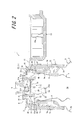
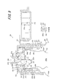
- a double container 1 according to the first embodiment of the present invention shown in FIG. 1 stores liquid contents such as food seasonings, and has a container body 2 and a dispensing cap 3. is doing.
- the container body 2 has a double structure of a delamination type having an inner layer body 4 and an outer layer body 5, and the dispensing cap 3 is attached to a mouth portion 5 a provided in the outer layer body 5.
- the container body 2 is not limited to the laminate peeling type, and may be a combination type in which the inner layer body (inner container) 4 and the outer layer body (outer container) 5 are individually molded and then combined.
- the inner layer body 4 constituting the container body 2 is formed into a flexible bag body with, for example, a thin synthetic resin, and the inside thereof is a housing portion 4a for housing the contents.
- the upper end portion of the inner layer body 4 is an upper opening 4b connected to the accommodating portion 4a, and the contents accommodated in the accommodating portion 4a can be poured out from the upper opening 4b.
- the outer layer body 5 forms an outer shell of the container body 2 and has the above-described mouth portion 5a and a body portion 5b integrally connected to the mouth portion 5a.
- the outer layer body 5 accommodates the inner layer body 4 in a peelable manner inside, and the upper opening 4b of the inner layer body 4 is fixed to the opening end of the mouth portion 5a.
- the mouth portion 5a of the outer layer body 5 is formed in a cylindrical shape, and a male screw portion 5c is integrally provided on the outer peripheral surface thereof.
- the mouth portion 5a of the outer layer body 5 is provided with a pair of apertures 6 penetrating the mouth portion 5a in the radial direction. These openings 6 communicate with each other between the inner layer body 4 and the outer layer body 5, and external air can be introduced between the inner layer body 4 and the outer layer body 5 through the opening 6.
- the number of apertures 6 is not limited to two, and at least one aperture may be provided.
- the dispensing cap 3 is formed in a cylindrical shape with a cylindrical wall 7 and a top wall 8 connected to the upper end of the cylindrical wall 7, and an internal thread 7 a is integrally formed on the inner peripheral surface of the cylindrical wall 7. Is provided.
- the dispensing cap 3 is attached to the mouth portion 5a of the outer layer body 5 by screwing the female screw portion 7a to the male screw portion 5c provided in the mouth portion 5a of the outer layer body 5.
- the pouring cap 3 attached to the mouth part 5 a covers the outer periphery of the mouth part 5 a with the cylindrical wall 7 and covers the upper part of the mouth part 5 a with the top wall 8.
- the top wall 8 of the dispensing cap 3 is provided with a cylindrical stepped portion 8a that protrudes upward.
- the stepped portion 8a is displaced from the axial center of the top wall 8 and is integrally provided with a spout (nozzle) 9. Is provided.
- the spout 9 protrudes in a trumpet shape from the upper surface of the stepped portion 8 a of the top wall 8, protrudes in a cylindrical shape from the lower surface of the stepped portion 8 a, and penetrates the top wall 8.
- the spout 9 communicates with the upper opening 4b of the inner layer body 4 so that the contents accommodated in the inner layer body 4 can be poured out.
- the upper side is the side on which the upper opening 4 b is provided with respect to the housing part 4 a of the inner layer body 4.
- the overcap 10 is provided in the pouring cap 3 through a hinge 11 so as to be opened and closed.
- the overcap 10 is formed in a cylindrical shape having substantially the same diameter as the pouring cap 3, and can be engaged with the pouring cap 3 by means such as undercut to keep the pouring cap 3 closed. it can.
- a cylindrical plug body 10 a that is inserted into the spout 9 when the overcap 10 is closed and closes the spout 9 is integrally formed on the inner surface of the overcap 10.
- the inner plug 12 is attached to the upper opening 4 b of the inner layer body 4.
- the inner plug 12 is made of, for example, a synthetic resin, and includes a substantially disc-shaped main body portion 13 and a cylindrical inner peripheral wall (spacer portion) 14 protruding upward from the outer peripheral edge of the main body portion 13. Yes.
- the inner peripheral wall 14 has an outer diameter that is substantially the same as the inner diameter of the cylindrical wall 7 of the dispensing cap 3, and the inner plug 12 fits the outer peripheral surface of the inner peripheral wall 14 to the inner peripheral surface of the cylindrical wall 7.
- the upper end of the inner peripheral wall 14 is in contact with the top wall 8 from the axial direction and is arranged inside the pouring cap 3.
- a space is provided between the inner plug 12 attached to the dispensing cap 3 and the top wall 8 of the dispensing cap 3.
- a cylindrical fitting tube portion 15 is coaxially and integrally provided on the lower surface of the main body portion 13 of the inner plug 12, that is, the surface facing the housing portion 4 a side of the inner layer body 4. It is liquid-tightly fitted inside 5a.
- the main body portion 13 of the inner plug 12 is provided with a pouring passage 16 formed as a through-hole penetrating the front and back surfaces thereof. And communicated with each other.
- a valve unit 21 made of, for example, synthetic resin, rubber, elastomer, silicon or the like is mounted in the space between the pouring cap 3 and the inner plug 12.
- the valve unit 21 has a cylindrical partition wall 21a.
- One end of the partition wall 21 a in the axial direction is fitted into an annular groove 13 a formed on the upper surface of the main body 13 of the inner plug 12, and the other end in the axial direction is formed on the lower surface of the top wall 8 of the dispensing cap 3. It is fitted into an annular groove 8 b formed coaxially with the annular groove 13 a and is fixed between the dispensing cap 3 and the inner plug 12.
- the inner space of the pouring cap 3 partitioned by the partition wall 21a is a pouring region 22 connecting the pouring channel 16 and the pouring port 9, and the content poured out from the pouring channel 16 is the pouring region. 22 flows through the spout 9.
- a check valve 21 ⁇ / b> A is integrally provided on the radially inner side of the partition wall 21 a in order to prevent outside air from being introduced from the extraction channel 16 into the accommodating portion 4 a of the inner layer body 4.
- the check valve 21A has a disc-shaped valve body 21b coaxial with the partition wall 21a.
- the valve body 21b is partitioned by a plurality of (for example, three) connecting pieces 21c that are elastically deformable at the outer peripheral edge thereof. It is connected to the inner peripheral surface of 21a and is movable in the axial direction (vertical direction) with respect to the partition wall 21a by elastic deformation of these connecting pieces 21c.
- the valve body 21b is disposed at the opening end of the pouring path 16 facing the pouring port 9 and closes the pouring path 16, and the outer layer body 5 is squeezed and the contents accommodated in the inner layer body 4 are It opens when pressure is applied, and the contents are circulated from the pouring channel 16 toward the pouring port 9. On the other hand, when the pressure applied to the contents is released after the contents are poured out, the valve body 21b returns to the position where the pouring path 16 is closed by the elastic force of the connecting piece 21c. Inflow of outside air from 16 to the accommodating portion 4a of the inner layer body 4 is prevented.
- the main body 13 of the inner plug 12 is integrally provided with a cylindrical tubular portion 23 adjacent to the pouring path 16.
- the cylindrical portion 23 opens to the housing portion 4a of the inner layer body 4 and the pouring region 22 of the pouring cap 3, and a ball 24 that is formed into a spherical shape by, for example, a steel material or a resin material is contained therein.
- the diameter of the ball 24 is equal to the inner diameter of the cylindrical portion 23 and is movable in the axial direction inside the cylindrical portion 23.
- a reduced diameter portion 23 a is integrally provided at the lower end of the cylindrical portion 23, and a part of the valve body 21 b is disposed at the upper end of the cylindrical portion 23, whereby the ball 24 is formed on the cylindrical portion 23. Retained inside.
- the ball 24 is located at the end of the cylindrical portion 23 on the side of the accommodating portion 4a by its own weight, and the double container 1 is in the upright posture.
- the contents are tilted by 90 degrees or more and are poured out, the contents move to the end of the cylindrical portion 23 on the side of the pouring region 22 as indicated by a broken line in the figure.
- the direction in which the ball 24 moves away from the pouring region 22 with the inside of the cylindrical portion 23 facing the accommodating portion 4a side In accordance with the movement, the contents accumulated in the spout 9 and the pour region 22 are drawn into the cylindrical portion 23 (suck back). Thereby, the dripping from the front-end
- an outside air introduction hole 31 is provided in the dispensing cap 3.
- the outside air introduction hole 31 is provided in the top wall 8 of the dispensing cap 3.
- a space outside the partition wall 21 a between the top wall 8 of the dispensing cap 3 and the inner plug 12 is a first ventilation region 32, and the outside air introduction hole 31 communicates with the first ventilation region 32.
- An opening is formed outside the pouring cap 3 on the side surface of the stepped portion 8a.
- the space between the cylindrical wall 7 of the pouring cap 3 and the mouth portion 5a of the outer layer body 5 is a second ventilation region 33, and the opening 6 provided in the mouth portion 5a of the outer layer body 5 is this
- the second vent region 33 is open.
- the male screw part 5c provided in the mouth part 5a is provided with a slit-like groove part 34 extending in the axial direction, and this groove part 34 also constitutes a part of the second ventilation region 33.
- a cylindrical fitting portion 5d having a larger diameter than the mouth portion 5a is integrally provided between the mouth portion 5a and the body portion 5b of the outer layer body 5, and the pouring cap 3 is provided on the outer peripheral surface of the fitting portion 5d.
- the lower end portion of the cylindrical wall 7 abuts and the lower end of the second ventilation region 33 is sealed.
- a throttle passage 35 is provided on the inner peripheral wall 14 of the inner plug 12 so as to be located above the upper opening 4b of the inner layer body 4 (on the opposite side of the upper opening 4b from the accommodating portion 4a).
- the throttle passage 35 has an enlarged diameter hole 35a having a tapered inner surface and a small hole 35b having a constant inner diameter provided in the bottom wall of the enlarged diameter hole 35a.
- a small hole 35 b of the throttle passage 35 opens into the first ventilation region 32, and a diameter-enlarged hole 35 a of the throttle passage 35 is a spiral passage formed between the outer peripheral surface of the inner peripheral wall 14 and the inner peripheral surface of the cylindrical wall 7. 36 is open.
- a communication groove 37 extending in the axial direction is formed at the lower end of the outer peripheral surface of the inner peripheral wall 14, and the spiral passage 36 is communicated with the second ventilation region 33 by the communication groove 37. That is, the first ventilation region 32 and the second ventilation region 33 are communicated with each other via the throttle passage 35.
- the small hole 35 b of the throttle passage 35 functions as an orifice, and can generate a predetermined resistance to the outside air (air) flowing between the first ventilation region 32 and the second ventilation region 33.
- a path for introducing outside air from the outside air introduction hole 31 to the opening 6 through the first ventilation region 32, the throttle passage 35 and the second ventilation region 33 is provided inside the dispensing cap 3. It is formed. Therefore, when the volume of the inner layer body 4 is reduced as the contents are poured out, the outside air can be introduced from the outside air introduction hole 31 through the path to the opening 6, that is, between the inner layer body 4 and the outer layer body 5. .
- the inner diameter of the small hole 35b of the throttle passage 35 is such that the content can be poured out when the outer layer body 5 is squeezed, and the outer layer body 5 can be poured out. It is set based on the rigidity of the squeeze, the restoring force after squeezing, and the like.
- a passage for ventilation from the outside air introduction hole 31 to the opening 6 through the first ventilation region 32 and the second ventilation region 33 is provided inside the dispensing cap 3, and the throttle is restricted in this route.
- the passage 35 is provided, outside air can be introduced between the opening 6, that is, between the inner layer body 4 and the outer layer body 5 through the path from the outside air introduction hole 31 as the contents are poured out.
- the outer layer body 5 is squeezed to pour out the contents, the air contained between the inner layer body 4 and the outer layer body 5 is kept in a high pressure state, and the contents contained in the inner layer body 4 Can be poured out from the spout 9 of the spout cap 3.
- the throttle passage 35 is provided integrally with the inner plug 12, there is no need to provide a separate part such as a check valve. Therefore, the number of parts of the double container 1 can be reduced to reduce its cost. Can do.
- the outside air introduction hole 31 is provided in the top wall 8 of the pouring cap 3 and the throttle passage 35 is provided in the inner peripheral wall 14 of the inner plug 12. If the throttle cap 35 is provided above the upper opening 4b of the inner layer body 4 provided in the dispensing cap 3, these arrangements can be variously changed as in the modified examples shown in FIGS. Can do. 2 to 6, the members corresponding to the members described above are denoted by the same reference numerals.
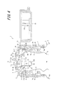
- the throttle passage 35 is provided in the top wall 8 of the pouring cap 3.
- the throttle passage 35 also serves as the outside air introduction hole 31, and can introduce outside air into the first ventilation region 32 inside the pouring cap 3 and release the air inside the first ventilation region 32 to the outside. it can.
- the throttling passage 35 also serve as the outside air introduction hole 31, the configuration of the double container 1 can be simplified and the cost can be further reduced.
- the throttle passage 35 has a tapered inner surface and has an enlarged diameter hole 35a that opens to the first ventilation region 32, and is provided in the bottom wall of the enlarged diameter hole 35a and opens to the outside. It can be set as the structure which has the small hole 35b with a constant internal diameter. Further, in order to allow the first ventilation region 32 and the second ventilation region 33 to communicate with each other, the inner peripheral wall 14 of the inner plug 12 has a longitudinal groove 41 provided on the inner peripheral surface thereof and extending in the axial direction, and an outer peripheral surface thereof. It is possible to adopt a configuration in which a notch portion 42 is provided which communicates with the vertical groove 41.
- vertical grooves 43 and 44 are provided on the inner peripheral surface and the outer peripheral surface of the inner peripheral wall 14 of the inner plug 12, respectively, and the thin cylindrical plate portion sandwiched between the vertical grooves 43 and 44 is narrowed down.
- a passage 35 is provided.
- the throttle passage 35 is formed as a small hole having a constant inner diameter, communicates with the first ventilation region 32 via a longitudinal groove 43 provided in the inner peripheral surface of the inner plug 12, and the outer peripheral surface of the inner plug 12. It communicates with the second ventilation region 33 through a vertical groove 44 provided in the inner space.
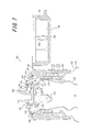
- the throttle passage 35 is provided in the cylindrical wall 7 of the extraction cap 3.
- the throttle passage 35 is provided above the upper opening 4 b of the inner layer body 4 and communicates with the second ventilation region 33 via a communication groove 37 provided on the outer peripheral surface of the inner peripheral wall 14.
- the ventilation region may be configured only by the second ventilation region 33.
- the throttle passage 35 also serves as the outside air introduction hole 31, and can introduce outside air into the second ventilation region 33 inside the extraction cap 3, and the second ventilation region 33. The air inside can be released to the outside. Therefore, the structure of the double container 1 can be simplified and the cost can be further reduced.
- the throttle passage 35 can be configured to have an enlarged diameter hole 35a and a small hole 35b.
- the gap between the dispensing cap 3 and the inner plug 12 is used as the throttle passage 35.
- a throttle groove 45 extending in the radial direction is formed on the inner surface of the top wall 8 of the dispensing cap 3, and the opening of the throttle groove 45 is closed by the upper end of the inner peripheral wall 14 of the inner plug 12.
- a gap formed by the throttle groove 45 between the dispensing cap 3 and the inner plug 12 serves as a throttle passage 35.
- One end of the throttle passage 35 communicates directly with the first ventilation region 32, and the other end communicates with the second ventilation region 33 via a spiral passage 36 and a communication groove 37.
- a throttle groove 45 is provided on the inner surface of the top wall 8 of the pouring cap 3 to form a throttling passage 35 between the pouring cap 3 and the inner plug 12. It is possible to adopt a configuration in which a throttle groove 45 is provided in the tip surface that contacts the 14 extraction caps 3 to form a throttle passage 35 between the extraction cap 3 and the inner plug 12, or A throttle groove 45 is provided on both the inner surface of the top wall 8 and the tip surface of the inner peripheral wall 14 that contacts the extraction cap 3 to form a throttle passage 35 between the extraction cap 3 and the inner plug 12. You can also
- the rigidity of the outer layer body 5, the restoring force after squeezing, etc. so that the contents can be poured out when the outer layer body 5 is squeezed.
- the inner diameter of the throttle passage 35 is adjusted, the resistance applied to the outside air (air) flowing in the ventilation path between the outside air introduction hole 31 and the opening 6 is adjusted only by the inner diameter of the throttle passage 35.
- the opening area of the outside air introduction hole 31 and the groove diameter of the communication groove 37 are adjusted.
- the resistance generated by the throttle passage 35 is combined with the cross-sectional area of other narrow grooves and the resistance generated by the hole, and the outside air flowing in the path ( The resistance applied to air) can be adjusted more widely. Rukoto can also.
- the check valve 21A is configured such that the valve body 21b is formed integrally with the partition wall 21a.
- Other configurations can be used as long as they exist.
- the valve body 21b is not limited to a flat plate shape, and may have various shapes as long as it has a structure capable of opening and closing the pouring path 16.
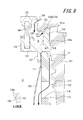
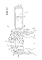
- FIG. 7 is a cross-sectional view of a main part of the double container according to the second embodiment of the present invention
- FIG. 8 is a partial enlarged cross-sectional view of the double container shown in FIG.
- symbol 101 shows the double container which is the 2nd Embodiment of this invention.
- the double container 101 includes an outer layer body 110 that forms an outer shell of the container, and an inner layer body 120 that is housed inside the outer layer body 110, and has an inner plug 130, a check valve 140 for contents, A pouring cap (pouring stopper) 150 and an overcap (lid body) 160 are provided.
- the double container 101 in the second embodiment is formed by laminating a synthetic resin outer layer body 110 and an inner layer body 120 formed of a synthetic resin having low compatibility with the outer layer body 110, This is obtained by blow molding a parison formed by laminating these synthetic resin materials.
- one or a plurality of adhesive bands that extend in the longitudinal direction between the outer layer body 110 and the inner layer body 120 and partially join the outer layer body 110 and the inner layer body 120. May be provided.
- the outer layer body 110 has a cylindrical mouth portion (mouth peripheral wall) 111 connected to a body portion 112 having flexible flexibility and a bottom portion (not shown) connected to the body portion 112.
- a male screw portion 113 is provided on the outer peripheral surface of the mouth portion 111.
- an opening (through hole) 114 is provided in the mouth portion 111, and a groove portion 115 in which the male screw portion 113 is notched in the vertical direction is provided on the outer peripheral surface provided with the opening 114.
- the inner peripheral wall 136 will be described in detail with reference to FIG. 8.
- the outer peripheral surface of the inner peripheral wall 136 is provided with a narrow groove (communication groove) 136 a extending in the vertical direction.
- a narrow groove 136b (a configuration similar to the narrow groove 136a) extending in the radial direction is provided.
- the lower part of the content check valve 140 includes a cylindrical portion 132 of the inner plug 130, a stepped portion 133, and a partition wall (annular wall) 141 fitted and held by the fitting wall 135.
- a plate-like valve portion 143 connected via a connecting piece (arm) 142 is provided on the radially inner side of the partition wall 141, and the extraction passage 134 is closed by the valve portion 143.
- the valve portion 143 also covers most of the upper opening of the cylindrical portion 132, but a portion of the valve portion 143 is always open.
- the check valve 140 for contents is in the form of a so-called three-point valve, but other check valves of other forms such as a one-point valve can be used.
- the partition wall 141 is cylindrical in the second embodiment, it may be rectangular.
- a pair of upper fitting walls 155 having a concentric double arrangement for fitting and holding the upper portion of the partition wall 141 are provided on the lower surface of the top wall 153.
- an outside air introduction hole 156 that penetrates the top wall 153 is provided on the radially outer side of the upper fitting wall 155.
- an internal space N is formed between the inner peripheral wall 136 and the partition wall 141 so as to be sandwiched between the main body 131 and the top wall 153 and open to the outside air introduction hole 156.
- a protrusion 157 protruding toward the internal space N is provided on the lower surface of the top wall 153 between the outside air introduction hole 156 and the inner peripheral wall 136.
- a connection path T2 constituted by the narrow groove 136b, and an internal space N connecting the connection path T2 and the outside air introduction hole 156 are formed.
- a convex rib extending in the vertical direction is provided on the outer peripheral surface of the inner peripheral wall 136, and when the inner plug 130 is incorporated into the dispensing cap 150, the convex rib becomes a spiral convex. It bites into the part 151a. As a result, the inner plug 130 is held against rotation with respect to the dispensing cap 150.
- a cylindrical fitting part having a larger diameter than the mouth part 111 is integrally provided between the mouth part 111 and the body part 112 of the outer layer body 110, and the pouring cap 150 is provided on the outer peripheral surface of the fitting part.
- the lower end portion of the cylindrical wall 151 is fitted.
- the lower end of the ventilation region including the ventilation passage T1, the connection passage T2, the internal space N, and the like is sealed with respect to the outside of the dispensing cap 150.
- the overcap (lid body) 160 is connected to the cylindrical wall 151 of the pouring cap 150 via the hinge 161, and the hinge 161 is bent, so that the pouring port 154 and the outside air introduction hole 156 can be covered. More specifically, the overcap 160 includes a flat plate-like upper wall 162 and a cover peripheral wall 163 that is connected to the edge of the upper wall 162 and is continuous with the cylindrical wall 151. Includes a plug (rod) 164 that enters the inside of the spout 154 and seals the spout 154 when the overcap 160 is closed. Note that the overcap 160 may be a separate body from the pouring cap 150 without providing the hinge 161, and may be configured to be attached to the pouring cap 150 with screws or undercuts.
- the overcap 160 When discharging the contents from the double container 101 according to the second embodiment configured as described above, the overcap 160 is opened as shown in FIG. Change posture to inverted posture. Thereby, the ball B in the cylindrical part 132 moves to the position (the spout 154 side) shown with a broken line in FIG. And when the trunk
- the opening 114 and the outside air introduction hole 156 are connected by the ventilation path T1, the connection path T2, and the internal space N, they are always open, but the narrow grooves 136a and the narrow grooves 136b Since the passage cross-sectional area (groove width and groove depth) is smaller than the other portions of the ventilation path T1, the connection path T2, and the internal space N and functions as a throttle path, even if the outer layer body 110 is pressed. The air between the outer layer body 110 and the inner layer body 120 does not leak so much, and the content pouring function is maintained at the same level as the conventional one.
- the extending length of the ventilation path T1 is increased by providing a spiral convex portion, it is possible to more effectively prevent air leakage.
- the restoring force can be adjusted by the material, thickness, shape, etc. of the outer layer body 110, and the cross-sectional areas (grooves) of the narrow grooves 136a and the narrow grooves 136b can be adjusted.
- the outer layer body 110 can be restored in the same time as in the case of using the air check valve.
- the desired performance is exhibited by changing the width and depth of the narrow groove, so that adjustment is easier than when using a check valve for air having a more complicated structure.
- the air check valve used conventionally since the air check valve used conventionally is not necessary, the cost can be reduced.
- the liquid may be sucked into the dispensing cap 150 together with air, but the sucked liquid is once taken into the internal space N.
- the connection path T2 is located above the internal space N, it is possible to effectively prevent the liquid from flowing into the ventilation path T1.
- the protrusion 157 is provided on the lower surface of the top wall 153, and the protrusion 157 enters between the outside air introduction hole 156 and the connection path T2. The liquid is prevented from flowing directly into the connection path T2, and the liquid can be prevented from flowing into the ventilation path T1 more reliably.
- the throttle passage is a narrow groove 136a provided on at least one of the outer peripheral surface of the inner peripheral wall 136 and the inner peripheral surface of the cylindrical wall 151, or a narrow groove provided on at least one of the upper surface of the inner peripheral wall 136 and the lower surface of the top wall 153. 136b.
- the spiral convex portion 151a protruding toward the other is provided on one of the inner peripheral wall 136 and the cylindrical wall 151, Since the extension length can be made longer, the air between the outer layer body 110 and the inner layer body 120 can be more difficult to leak out from the outside air introduction hole 156.
- the protrusion cap 150 is provided with a protrusion 157 protruding from the lower surface of the top wall 153 between the outside air introduction hole 156 and the inner peripheral wall 136. Since the liquid sucked from the outside air introduction hole 156 can be prevented from flowing directly into the connection path T2, the penetration of the liquid into the rear side of the pouring cap 150 or between the outer layer body 110 and the inner layer body 120 is prevented. Can be more reliably prevented.
- the inner plug 130 is provided with a cylindrical portion 132 that extends toward the accommodating portion S, and the inside of the cylindrical portion 132 of the outer layer body 110 is provided.
- air is introduced into the opening 114 through the groove 115 provided in the outer layer body 110.
- the air is passed through the gap between the male screw 113 and the female screw 152. Air may be introduced.
- the two narrow grooves 136a and 136b are provided, but either one may be provided. Further, instead of the narrow groove 136a, the passage cross-sectional area of another part constituting the air passage T1 may be narrowed. Further, although the narrow grooves 136a and 136b are provided on the inner peripheral wall 136, they may be provided on the cylindrical wall 151, or may be divided into two parts. Further, although the spiral convex portion 151a is provided on the cylindrical wall 151, it may be provided on the inner peripheral wall 136 or on both.
- outer layer body 110 and the inner layer body 120 are not limited to those formed by blow molding a parison having a laminated structure, and the outer layer body 110 and the inner layer body 120 are individually formed, and then the inner layer body 120 is formed into the outer layer body. It may be installed in 110.
- a double container 201 according to the third embodiment of the present invention shown in FIG. 9 stores liquid contents such as food seasonings and has a container body 202 and a dispensing cap 203. ing.
- the container main body 202 has a double layer structure of an exfoliation type having an inner layer body 204 and an outer layer body 205, and the dispensing cap 203 is attached to a mouth portion 205 a provided in the outer layer body 205.
- the container main body 202 is not limited to the laminate peeling type, and may be a combination type in which the inner layer body (inner container) 204 and the outer layer body (outer container) 205 are individually molded and then combined.
- the inner layer body 204 constituting the container main body 202 is formed into a flexible bag body by, for example, a thin synthetic resin, and the inside thereof is a housing portion 204a for storing contents.
- the upper end portion of the inner layer body 204 is an upper opening 204b connected to the accommodation portion 204a, and the contents accommodated in the accommodation portion 204a can be poured out from the upper opening 204b.
- the outer layer body 205 forms an outer shell of the container main body 202, and has the above-described mouth part 205a and a body part 205b integrally connected to the mouth part 205a.
- the outer layer body 205 accommodates the inner layer body 204 in a peelable manner inside, and an upper opening 204b of the inner layer body 204 is fixed to the opening end of the mouth portion 205a.
- the dispensing cap 203 is formed in a cylindrical shape having a cylindrical cylindrical wall 207 and a top wall 208 connected to the upper end of the cylindrical wall 207, and an internal thread portion 207 a is integrally formed on the inner peripheral surface of the cylindrical wall 207. Is provided.
- the dispensing cap 203 is attached to the mouth portion 205a of the outer layer body 205 by screwing a female screw portion 207a to a male screw portion 205c provided in the mouth portion 205a of the outer layer body 205.
- the pouring cap 203 attached to the mouth part 205 a covers the outer periphery of the mouth part 205 a with the cylindrical wall 207 and covers the upper part of the mouth part 205 a with the top wall 208.
- the inner plug 212 is attached to the upper opening 204 b of the inner layer body 204.
- the inner plug 212 is made of, for example, a synthetic resin, and includes a substantially disc-shaped main body 213 and a cylindrical inner peripheral wall (spacer portion) 214 protruding upward from the outer peripheral edge of the main body 213.
- the inner peripheral wall 214 has an outer diameter that is substantially the same as the inner diameter of the cylindrical wall 207 of the dispensing cap 203, and the inner plug 212 fits the outer peripheral surface of the inner peripheral wall 214 to the inner peripheral surface of the cylindrical wall 207.
- the upper end of the inner peripheral wall 214 is in contact with the top wall 208 from the axial direction and is arranged inside the pouring cap 203.
- a space is provided between the inner plug 212 attached to the dispensing cap 203 and the top wall 208 of the dispensing cap 203.
- a cylindrical fitting tube portion 215 is coaxially and integrally provided on the lower surface of the main body portion 213 of the inner plug 212, that is, the surface facing the accommodating portion 204 a of the inner layer body 204. It is liquid-tightly fitted inside 205a.
- the main body portion 213 of the inner plug 212 is provided with a pouring passage 216 formed as a through-hole penetrating the front and back, and the pouring passage 216 allows the container 204 a of the inner layer body 204 and the spout 209 of the pouring cap 203 to be discharged. And communicated with each other.
- valve unit 221 made of, for example, synthetic resin, rubber, elastomer, silicon or the like is mounted in the space between the pouring cap 203 and the inner stopper 212.
- the valve unit 221 has a cylindrical partition wall 221a.
- One end of the partition wall 221a is fitted in an annular groove 213a formed on the upper surface of the main body 213 of the inner plug 212, and the other end in the axial direction is formed on the lower surface of the top wall 208 of the dispensing cap 203. It is fitted into an annular groove 208 b formed coaxially with the annular groove 213 a and is fixed between the pouring cap 203 and the inner plug 212.
- An inner space of the pouring cap 203 partitioned by the partition wall 221a is a pouring area 222 that connects the pouring path 216 and the pouring outlet 209, and the content poured out from the pouring path 216 is the pouring area. It flows through 222 into the spout 209.
- the valve body 221b is disposed at the opening end of the pouring path 216 facing the pouring port 209 and closes the pouring path 216.
- the outer layer body 205 is squeezed, etc. It opens when pressure is applied, and the contents are circulated from the pouring channel 216 toward the pouring port 209. On the other hand, when the pressure applied to the contents is released after the contents are poured out, the valve body 221b returns to the position where the pouring path 216 is closed by the elastic force of the connecting piece 221c. Inflow of outside air from the H.216 to the accommodating portion 204a of the inner layer body 204 is prevented.
- a cylindrical tubular portion 223 is integrally provided on the main body portion 213 of the inner plug 212 adjacent to the extraction channel 216.
- the cylindrical portion 223 opens to the accommodating portion 204a of the inner layer body 204 and the extraction region 222 of the extraction cap 203, and a ball 224 that is formed into a spherical shape by, for example, a steel material or a resin material is provided therein.
- the diameter of the ball 224 is equal to the inner diameter of the cylindrical portion 223 and is movable in the axial direction inside the cylindrical portion 223.
- a reduced diameter portion 223 a is integrally provided at the lower end of the cylindrical portion 223, and a part of the valve body 221 b is disposed at the upper end of the cylindrical portion 223, so that the ball 224 can be attached to the cylindrical portion 223. Retained inside.
- the ball 224 is positioned at the end of the cylindrical portion 223 on the side of the accommodating portion 204a by its own weight, and the double container 201 is in the standing posture.
- the contents are poured out at an angle of 90 degrees or more, as shown by a broken line in FIG. 9, the contents move to the end of the cylindrical portion 223 on the side of the extraction region 222.
- a space between the cylindrical wall 207 of the dispensing cap 203 and the mouth portion 205a of the outer layer body 205 serves as a ventilation region 231.
- An opening 206 provided in the mouth portion 205a of the outer layer body 205 is provided in the ventilation region 231. It is open.
- a male thread part 205c provided in the mouth part 205a is provided with a slit-like groove part 232 extending in the axial direction, and this groove part 232 also constitutes a part of the ventilation region 231.
- a cylindrical fitting portion 205d having a diameter larger than that of the mouth portion 205a is integrally provided between the mouth portion 205a and the body portion 205b of the outer layer body 205, and the pouring cap 203 is provided on the outer peripheral surface of the fitting portion 205d.
- the lower end portion of the cylindrical wall 207 is fitted.
- the lower end of the ventilation region 231 is sealed and partitioned from the outside of the pouring cap 203.
- the upper side of the ventilation region 231 is such that the lower surface of the inner plug 212 comes into contact with the open end (upper end) of the mouth portion 205 a and the upper end of the inner peripheral wall 214 comes into contact with the inner surface of the top wall 208 of the dispensing cap 203. It is sealed.
- the pouring cap 203 has a lower part than the upper opening 204b of the inner layer body 204 (with respect to the upper opening 204b, A throttling passage 233 is provided on the side.
- the throttle passage 233 is formed in the axial direction of the cylindrical wall 207 on the inner peripheral surface of the lower end portion of the cylindrical wall 207 that fits the outer peripheral surface of the fitting portion 205d of the outer layer body 205. Is formed in a groove shape having a rectangular cross section extending along the line.
- the throttle passage 233 functions as an orifice, even if the outer layer body 205 is squeezed and the pressure of air between the inner layer body 204 and the outer layer body 205 is increased, the air passes through the throttle passage 233. When a large resistance is applied, it cannot easily flow out. That is, the pressure of the air between the inner layer body 204 and the outer layer body 205, which has been increased by the squeeze of the outer layer body 205, is gradually reduced without being rapidly reduced.
- the pressure of the air between the inner layer body 204 and the outer layer body 205 is caused to pour out the contents from the inner layer body 204 for a while. It can be kept in a high enough state.
- the inner layer body 204 is crushed through the air whose pressure between the inner layer body 204 and the outer layer body 205 is increased, and the contents stored in the storage portion 204a Can be poured out from the spout 209 of the spout cap 203.
- the cross-sectional area of the throttle passage 233 formed in the groove shape is such that the content can be dispensed so that the content can be dispensed when the outer layer body 205 is squeezed. It is set based on the rigidity of the outer layer body 205, the restoring force after squeezing, and the like.
- the extraction cap 203 is provided with the throttle passage 233, and the outside air is introduced and discharged between the inner layer body 204 and the outer layer body 205 and the outside of the extraction cap 203 through the throttle passage 233.
- outside air can be introduced from the throttle passage 233 into the opening 206, that is, between the inner layer body 204 and the outer layer body 205 as the contents are poured out, and the outer layer is poured out for the contents to be poured out.
- the body 205 is squeezed, the air between the inner layer body 204 and the outer layer body 205 is kept in a high pressure state, and the contents contained in the inner layer body 204 are removed from the spout 209 of the spout cap 203. Can be poured out to the outside.
- the throttle passage 233 is integrally formed in a groove shape on the cylindrical wall 207 of the dispensing cap 203, there is no need to provide a separate part such as a check valve. The number of parts can be reduced, and the cost can be reduced.
- the throttle passage 233 is provided below the upper opening 204b of the inner layer body 204, when the throttle passage 233 is provided, the configuration of the portion other than the groove of the inner plug 212 and the extraction cap 203 is simplified, The cost of the double container 201 can be further reduced.
- FIG. 10 is a modification of the double container shown in FIG. 1, and is a cross-sectional view showing a case where a throttle passage is provided in the cylindrical wall of the extraction cap.
- members corresponding to those described in FIG. 9 are denoted by the same reference numerals.
- the throttle passage 233 is provided in the cylindrical wall 207 of the extraction cap 203 as a through hole that penetrates the cylindrical wall 207 in the radial direction. Also in this case, the throttle passage 233 is provided below the upper opening 204 b of the inner layer body 204 and below the opening 206.
- the throttle passage 233 in this modification has a large-diameter enlarged hole 233a having a tapered inner surface and a small-diameter enlarged hole 233b having a tapered inner surface having a smaller diameter than the large-diameter enlarged hole 233a.
- the large-diameter enlarged hole 233a opens to the outside of the pouring cap 203, and the small-diameter enlarged hole 233b opens to the ventilation region 231.
- the small-diameter enlarged hole 233b of the throttle passage 233 functions as an orifice, and causes a predetermined resistance to the outside air (air) flowing through the throttle passage 233 between the outside of the extraction cap 203 and the ventilation region 231. Even with the configuration of such a modification, the same effect as that shown in FIG. 9 can be produced.
- the throttle passage 233 is provided in a groove shape on the inner peripheral surface of the lower end portion of the cylindrical wall 207 of the dispensing cap 203.
- the passage 233 is provided as a through hole in the cylindrical wall 207 of the dispensing cap 203.
- the passage 233 is not limited to this, and is provided below the upper opening 204b of the inner layer body 204 to communicate the ventilation region 231 with the outside.
- the throttle passage 233 can have other configurations and arrangements.
- path 216 is integrally formed with the partition wall 221a, if it can open and close the extraction channel
- symbol 301 shows the double container which is the 4th Embodiment of this invention.
- the double container 301 includes an inner layer body 310 that contains the content liquid and an outer layer body 320 that houses the inner layer body 310 inside, and further includes an inner plug 330, a check valve 340, a ball (moving valve) 350, A dispensing cap 360 and an overcap (cover) 370 are provided.
- the inner layer body 310 includes an accommodating portion (filling space) S for accommodating the content liquid therein.
- the inner layer 310 is made of a thin synthetic resin, and is capable of volume reduction deformation.
- the outer layer body 320 has a trunk portion 321 connected to a bottom portion (not shown), and a stepped cylindrical mouth portion (mouth peripheral wall) 322 whose lower portion has a larger diameter than the upper portion is integrally connected to the trunk portion 321. Is.
- An upper opening 322 a that opens upward is provided in the mouth 322, and a male screw part 322 b is provided on the outer peripheral surface of the mouth 322.
- the opening 322 is provided with an opening (through opening) 323 for introducing air between the inner layer body 310 and the outer layer body 320, and further, the opening 323 of the opening 323 is located.
- a groove portion 324 is provided on the outer peripheral surface to cut out the male screw portion 322b in the vertical direction.
- the upper opening of the inner layer body 310 is disposed inside the mouth portion 322 of the outer layer body 320 and opens together with the upper opening 322 a of the mouth portion 322.
- the inner layer body 310 and the outer layer body 320 are obtained by laminating synthetic resins having low compatibility with each other so as to be peelable, and blow molding a parison formed by laminating these synthetic resin materials. It is obtained by doing.
- a preform formed into a test tube is biaxially stretch blow molded, or an outer layer body and an inner layer body are individually formed, and then the inner layer body is mounted in the outer layer body. It may be used.
- one or a plurality of adhesive bands extending in the longitudinal direction between the inner layer body 310 and the outer layer body 320 and partially joining the inner layer body 310 and the outer layer body 320. May be provided.
- the inner plug 330 has a main body (top wall) 331 that covers the upper opening 322 a of the outer layer body 320.
- the main body portion 331 is provided with a cylindrical portion (cylindrical wall) 332 that penetrates up and down and extends toward the housing portion S.
- the cylindrical portion 332 of the present embodiment is a cylindrical shape in which the cross-sectional shape of the inner peripheral surface thereof is a circle, but is a rectangular tube shape in which the cross-sectional shape of the inner peripheral surface is a polygon such as a quadrangle or a hexagon. It may be a thing.
- the cylindrical portion 332 is provided with a reduced diameter portion 332a that narrows the inner diameter as it goes downward.
- the main body portion 331 is provided with a step portion 333 that has an upward convex shape adjacent to the cylindrical portion 332, and a pouring passage 334 that penetrates the front and back is provided in the step portion 333.
- an annular fitting wall 335 is provided on the upper surface of the main body portion 331 to surround the cylindrical portion 332 and the stepped portion 333 and to fit and hold the check valve 340 therebetween.
- a cylindrical inner peripheral wall 336 that stands up from the edge of the main body 331 is provided on the radially outer side of the fitting wall 335.
- An annular fitting tube portion (seal wall) 337 that is liquid-tightly fitted inside the mouth portion 322 is provided on the lower surface of the main body portion 331.
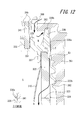
- the inner peripheral wall 336 will be described in detail with reference to FIG. 12.
- a vertical groove (groove portion) 336 a extending in the vertical direction is provided on the outer edge of the inner peripheral wall 336.
- the cross-sectional shape of the communication groove 336a in the fourth embodiment has a triangular shape as shown in the CC cross section of FIG. 12, but various shapes such as a semicircular shape and a rectangular shape can be used. Can be adopted.
- a total of two are provided by opposing arrangement
- a lateral groove 336 b extending in the radial direction is provided on the upper surface of the inner peripheral wall 336.
- the lower portion of the check valve 340 includes a cylindrical portion 332, a step portion 333, and a partition wall (annular wall) 341 that is fitted and held on the fitting wall 335.
- a plate-like valve body 343 connected via a connecting piece (elastic arm) 342 is provided on the radially inner side of the partition wall 341, and the extraction passage 334 is closed by the valve body 343.
- the valve body 343 also covers most of the upper opening of the cylindrical portion 332, but a part of the valve body 343 is always open.
- the check valve 340 is in the form of a so-called three-point valve, but other types of check valves in the past, such as a one-point valve, can be used.
- the partition wall 341 is cylindrical, but may be rectangular.
- the dispensing cap 360 includes a cylindrical wall (outer peripheral wall) 361 that surrounds the mouth portion 322, and a female screw portion 362 corresponding to the male screw portion 322 b of the mouth portion 322 is provided on the inner peripheral surface of the cylindrical wall 361. .
- a top wall 363 that covers the inner plug 330 and the check valve 340 is provided on the upper portion of the cylindrical wall 361.
- the top wall 363 is provided with a spout (pouring cylinder) 364 that pours the content liquid in the storage portion S under the open check valve 340. Note that the spout 364 also extends to the lower side of the top wall 363, thereby functioning as a stopper when the valve body 343 is excessively lifted.
- a pair of upper fitting walls 365 in a concentric double arrangement for fitting and holding the upper portion of the partition wall 341 is provided on the lower surface of the top wall 363. Furthermore, an outside air introduction hole 366 that penetrates the top wall 363 is provided on the radially outer side of the upper fitting wall 365. As a result, the space between the spout 364 and the outside air introduction hole 366 is partitioned by the partition wall 341, and an internal space N in which the outside air introduction hole 366 opens is formed outside the partition wall 341 in the radial direction.
- a region in the vicinity of the communication groove 336a on the inner peripheral surface of the cylindrical wall 361 is in contact with the outer peripheral surface of the inner peripheral wall 336 except for the communication groove (vertical groove) 336a serving as a groove portion, and the lateral groove 336b on the lower surface of the top wall 363.
- the region in the vicinity of is in contact with the upper surface of the inner peripheral wall 336 except for the lateral groove 336b.
- outside air introduction path (venting region) T3 that reaches the opening 323 through the gap with the inner peripheral wall 336, the communication groove 336a, and the groove portion 324 is formed.
- the number of outside air introduction paths T3 may be one or three or more.
- the communication groove 336a has the minimum cross-sectional area of the outside air introduction path T3.
- the minimum cross-sectional area of the outside air introduction path T3 is the minimum between the outside air introduction hole 366 and the opening 323 in the cross-sectional area in a plane orthogonal to the extending direction of the outside air introduction path T3.
- the cross-sectional area in the horizontal plane of the communication groove 336a is the minimum between the outside air introduction hole 366 and the opening 23.
- the total cross-sectional area of each communication groove 336a on the horizontal plane is set to fall within the range of 0.11 to 0.19 mm 2 .
- a cylindrical fitting portion having a larger diameter than the mouth portion 322 is integrally provided between the mouth portion 322 and the body portion 321 of the outer layer body 320, and the extraction cap 360 is provided on the outer peripheral surface of the fitting portion.
- the lower end portion of the cylindrical wall 361 is fitted.
- the lower end of the ventilation region including the outside air introduction path T3 is sealed off and partitioned from the outside of the dispensing cap 360.
- the overcap 370 is connected to the cylindrical wall 361 of the pouring cap 360 via the hinge 371, and the hinge 371 is bent so as to cover the pouring port 364 and the outside air introduction hole 366. More specifically, the overcap 370 includes a flat plate-like upper wall 372 and a lid peripheral wall 373 connected to the edge of the upper wall 372 and connected to the cylindrical wall 361. Is provided with a rod-shaped plug (seal part) 374 that enters the inside of the spout 364 and seals the spout 364 when the overcap 370 is closed. Note that the overcap 370 may be configured separately from the pouring cap 360 without providing the hinge 371 and attached to the pouring cap 360 with a screw or undercut.
- the overcap 370 is opened as shown in FIG. 11, and the posture of the double container 301 is changed from the standing posture to the tilted or inverted posture.
- the inner layer body 310 is pressed from the outer layer body 320 directly or via the air between the inner layer body 310 and the outer layer body 320 to pressurize the accommodating portion S.
- the pressurized content liquid pushes up the valve body 343 from the extraction path 334, the content liquid flows out from the extraction path 334, and is poured out to the outside through the spout 364.
- the pressure on the body 321 of the outer layer body 320 is released.
- the pressure in the storage portion S is reduced, and the valve body 343 closes the extraction passage 334, so that outside air can be prevented from entering the storage portion S.
- the outer layer body 320 tries to return to its original shape by its own restoring force, and since the mutual pressure between the inner layer body 310 and the outer layer body 320 is negative, outside air is introduced through the outside air introduction path T3. .
- the outer layer body 320 is restored while the volume of the inner layer body 310 is reduced.
- the valve body 343 closes the pouring path 334, the content liquid remains in the pouring outlet 364.
- the ball 350 has its own weight. Or move downward due to the pressure drop in the housing part S.
- a space corresponding to the amount of movement of the ball 50 is formed above the cylindrical portion 332, so that the content liquid corresponding to this space can be pulled back from the spout 364 (suck back). Function), dripping can be effectively prevented. Since the ball 350 moved downward is seated on the reduced diameter portion 332a of the cylindrical portion 332, the inside of the accommodating portion S can be kept closed.
- the outside air introduction path T3 that is at least one ventilation region from the outside air introduction hole 366 to the opening 323 is provided inside the pouring cap 360, Since the sum of the minimum cross-sectional areas in the outside air introduction path T3 is 0.11 to 0.19 mm 2 , when the outer layer body 320 is pressed, the air between the outer layer body 320 and the inner layer body 310 passes through the outside air introduction hole 366. Since the storage part S can be sufficiently pressurized without leaking so much, the content liquid can be poured out well. Moreover, if it is the said range, since it does not take too much time for completion of the restoration
- one member in order to keep the sum of the minimum cross-sectional areas in the outside air introduction passage T3 within the above range, for example, one member is provided with a through hole, and the opening of the through hole is provided. This can be realized even if the area is within the above range, but the inner diameter of the through-hole becomes small, so that it may be difficult to form.
- a groove portion (communication groove 336a) that forms a part of the outside air introduction path T3 on at least one of the outer edge of the inner plug 330 and the cylindrical wall 361 of the dispensing cap 360 and has a minimum cross-sectional area of the outside air introduction path T3.
- the grooves are formed on the outer surface or the inner surface of each member, so that the grooves can be easily formed.
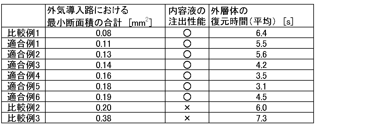
- the content liquid pouring performance when the outer layer body was pressed and the restoration time of the outer layer body were investigated.
- the investigation is to prepare a double container in which the cross-sectional area of each of the two communication grooves 336a is changed in order to change the total of the minimum cross-sectional area in the outside air introduction path while filling the same type and the same amount of the content liquid. This was confirmed by pressing the outer layer body and repeatedly pouring out a predetermined amount of the content liquid.
- the results are shown in Table 1 together with the total cross-sectional area of the communication groove 336a.
- the capacity of the double container was 200 ml.
- the content liquid pouring performance was confirmed by pressing the outer layer body to ensure that the content liquid was well poured out.
- “ ⁇ ” indicates that the content liquid was successfully dispensed
- “ ⁇ ” indicates that the content liquid cannot be dispensed unless the outer layer body is pressed strongly, or is completely dispensed even if pressed strongly. Indicates that you could not do it.
- the restoration time of the outer layer was measured from the time when the outer layer was released until the outer layer was restored.
- the results in Table 1 show the average of the time taken to complete restoration for a plurality of double containers per type. If the restoration time was less than 6 s on average, it was determined that there was no problem in actual use.
- double containers having the above numerical range of 0.14 to 0.19 mm 2 are preferable because the restoration time of the outer layer body becomes shorter, and the above numerical range is 0.16 to 0.16. It can be seen that a double container of 0.18 mm 2 (Compliant Examples 4 and 5) is more suitable because the restoration time of the outer layer body is further shortened.
- the double container shown in FIG. 11 and FIG. 12 has the same structure, and the double container having a different capacity was examined for the restoration time of the outer layer body.
- the results are shown in Table 2 together with the capacity of the double container used in the investigation.
- the sum total of those cross-sectional areas was 0.14 mm ⁇ 2 >.
- the portion having the minimum cross-sectional area in the outside air introduction path is not limited to the outer edge of the inner plug, and can be appropriately provided between the outside air introduction hole and the through opening.
Abstract
Description

4:内層体 4a:収容部 4b:上部開口
5:外層体 5a:口部 5b:胴部
5c:雄ねじ部 5d:嵌合部 6:開孔
7:円筒壁 7a:雌ねじ部 8:頂壁
8a:段差部 8b:環状溝 9:注出口
10:オーバーキャップ 10a:栓体 11:ヒンジ
12:中栓 13:本体部 13a:環状溝
14:内周壁 15:嵌合筒部 16:注出路
21:弁ユニット 21A:逆止弁 21a:区画壁
21b:弁部 21c:連結片 22:注出領域
23:筒状部 23a:縮径部 24:ボール
31:外気導入孔 32:第1通気領域 33:第2通気領域
34:溝部 35:絞り通路 35a:拡径孔
35b:小孔 36:螺旋状通路 37:連通溝
41:縦溝 42:切り欠き部 43、44:縦溝
45:絞り溝 101:二重容器 110:外層体
111:口部 112:胴部 113:雄ねじ部
114:開孔 115:溝部 120:内層体
121:上部開口 130:中栓 131:本体部
132:筒状部 133:段部 134:注出路
135:嵌合壁 136:内周壁 136a:細溝(絞り通路)
136b:細溝(絞り通路)137:嵌合筒部 140:内容物用逆止弁
141:区画壁 142:連結片 143:弁部
150:注出キャップ 151:円筒壁 151a:螺旋状の凸部
152:雌ねじ部 153:頂壁 154:注出口
155:上部嵌合壁 156:外気導入孔 157:突起
160:オーバーキャップ 161:ヒンジ 162:上壁
163:蓋体周壁 164:栓体 201:二重容器
202:容器本体 203:注出キャップ 204:内層体
204a:収容部 204b:上部開口 205:外層体
205a:口部 205b:胴部 205c:雄ねじ部
205d:嵌合部 206:開孔 207:円筒壁
207a:雌ねじ部 208:頂壁 208a:段差部
208b:環状溝 209:注出口 210:オーバーキャップ
210a:栓体 211:ヒンジ 212:中栓
213:本体部 213a:環状溝 214:内周壁
215:嵌合筒部 216:注出路 221:弁ユニット
221A:逆止弁 221a:区画壁 221b:弁体
221c:連結片 222:注出領域 223:筒状部
223a:縮径部 224:ボール 231:通気領域
232:溝部 233:絞り通路 233a:大径拡径孔
233b:小径拡径孔 301:二重容器 310:内層体
320:外層体 321:胴部 322:口部
322a:上部開口 322b:雄ねじ部 323:開孔
324:溝部 330:中栓 331:本体部
332:筒状部 332a:縮径部 333:段部
334:注出路 335:嵌合壁 336:内周壁
336a:連通溝(溝部) 336b:横溝 337:嵌合筒部
340:逆止弁 341:区画壁 342:連結片
343:弁体 350:ボール 360:注出キャップ
361:円筒壁 362:雌ねじ部 363:頂壁
364:注出口 365:上部嵌合壁 366:外気導入孔
370:オーバーキャップ 371:ヒンジ 372:上壁
373:蓋体周壁 374:栓体 B:球状体
N:内部空間 S:収容部 T1:通気路
T2:接続路 T3:外気導入路 1: Double container 2: Container body 3: Pouring cap 4: Inner layer body 4a: Housing part 4b: Upper opening 5: Outer layer body 5a: Mouth part 5b: Body part 5c: Male thread part 5d: Fitting part 6: Open Hole 7: Cylindrical wall 7a: Female thread portion 8: Top wall 8a: Stepped portion 8b: Annular groove 9: Outlet 10: Overcap 10a: Plug body 11: Hinge 12: Medium plug 13: Main body part 13a: Annular groove 14: Inner peripheral wall 15: fitting cylinder portion 16: dispensing path 21: valve unit 21A: check valve 21a: partition wall 21b: valve portion 21c: connecting piece 22: dispensing area 23: tubular portion 23a: reduced diameter portion 24: Ball 31: Outside air introduction hole 32: First ventilation area 33: Second ventilation area 34: Groove 35: Restriction passage 35a: Expanded hole 35b: Small hole 36: Spiral passage 37: Communication groove 41: Vertical groove 42: Notch part 43, 44: Vertical groove 45: Drawing groove 101: Double container 110: Outer layer body 111: Mouth part 112: Body part 113: Male thread part 114 : Opening 115: Groove 120: Inner layer body 121: Upper opening 130: Inner plug 131: Main body part 132: Cylindrical part 133: Step part 134: Outlet path 135: Fitting wall 136: Inner peripheral wall 136a: Narrow groove (throttle) aisle)
136b: narrow groove (throttle passage) 137: fitting cylinder part 140: check valve for contents 141: partition wall 142: connecting piece 143: valve part 150: pouring cap 151: cylindrical wall 151a: spiral convex part 152: Female thread portion 153: Top wall 154: Outlet 155: Upper fitting wall 156: Outside air introduction hole 157: Projection 160: Overcap 161: Hinge 162: Upper wall 163: Lid peripheral wall 164: Plug body 201: Double Container 202: Container main body 203: Pouring cap 204: Inner layer body 204a: Housing part 204b: Upper opening 205: Outer layer body 205a: Mouth part 205b: Body part 205c: Male thread part 205d: Fitting part 206: Opening 207: Cylinder Wall 207a: Female thread portion 208: Top wall 208a: Stepped portion 208b: Annular groove 209: Note Port 210: Overcap 210a: Plug 211: Hinge 212: Inner plug 213: Main body 213a: Annular groove 214: Inner peripheral wall 215: Fitting cylinder 216: Outlet 221: Valve unit 221A: Check valve 221a: Partition Wall 221b: Valve body 221c: Connecting piece 222: Extraction region 223: Tubular portion 223a: Reduced diameter portion 224: Ball 231: Ventilation region 232: Groove portion 233: Restriction passage 233a: Large diameter expanded hole 233b: Small diameter expanded diameter Hole 301: Double container 310: Inner layer body 320: Outer layer body 321: Body part 322: Mouth part 322a: Upper opening 322b: Male screw part 323: Open hole 324: Groove part 330: Inner plug 331: Main body part 332: Tubular part 332a: Reduced diameter portion 333: Step portion 334: Pouring path 335: Fitting wall 336: inner peripheral wall 336a: communication groove (groove portion) 336b: lateral groove 337: fitting cylinder portion 340: check valve 341: partition wall 342: connecting piece 343: valve body 350: ball 360: dispensing cap 361: cylindrical wall 362 : Female thread part 363: Top wall 364: Outlet 365: Upper fitting wall 366: Outside air introduction hole 370: Overcap 371: Hinge 372: Upper wall 373: Lid peripheral wall 374: Plug B: Spherical body N: Internal space S: accommodating part T1: ventilation path T2: connection path T3: outside air introduction path
Claims (17)
- 内容物の収容部につながる上部開口を備えた内層体と、該内層体を収容するとともに該内層体との間に外気を導入する開孔を口部に備えた外層体と、内容物の注出口を備え、前記外層体の口部に装着された注出キャップと、を有する二重容器であって、
前記収容部と前記注出口とを連通させる注出路を備え、前記上部開口に装着された中栓と、
前記注出路を開閉する逆止弁と、を備え、
前記注出キャップの内側に通気領域を設け、
前記通気領域を外部に連通させる外気導入孔から前記通気領域を介して前記開孔に至る経路中に絞り通路を設けたことを特徴とする二重容器。 An inner layer body provided with an upper opening connected to the contents accommodating portion, an outer layer body that accommodates the inner layer body and has an opening in the mouth for introducing outside air between the inner layer body, and an injection of the contents A double container having an outlet and a pouring cap attached to the mouth of the outer layer body,
A pouring path for communicating the accommodating portion and the pouring port, and an inner plug attached to the upper opening;
A check valve that opens and closes the extraction path,
Provide a ventilation area inside the dispensing cap,
A double container, wherein a throttle passage is provided in a path from an outside air introduction hole that communicates the ventilation region to the outside through the ventilation region to the opening. - 前記外気導入孔を前記注出キャップに設け、
前記注出キャップの前記口部の外周を覆う円筒壁の下端部分を前記外層体の外周面に嵌合させて前記通気領域の下端を密封し、
前記注出キャップと前記中栓との間に、前記注出キャップの内側を、前記注出路と前記注出口とを連ねる注出領域と前記通気領域とに区画する区画壁を設け、
前記絞り通路を前記上部開口よりも上方に位置して設けた請求項1に記載の二重容器。 The outside air introduction hole is provided in the dispensing cap,
Fitting the lower end portion of the cylindrical wall covering the outer periphery of the mouth of the pouring cap to the outer peripheral surface of the outer layer body to seal the lower end of the ventilation region;
A partition wall is provided between the pouring cap and the inner plug to divide the inner side of the pouring cap into a pouring region connecting the pouring passage and the pouring port and the ventilation region,
The double container according to claim 1, wherein the throttle passage is provided above the upper opening. - 前記絞り通路を前記外気導入孔とともに前記注出キャップに設けた請求項2に記載の二重容器。 The double container according to claim 2, wherein the throttle passage is provided in the extraction cap together with the outside air introduction hole.
- 前記絞り通路を前記中栓に設けた請求項2に記載の二重容器。 The double container according to claim 2, wherein the throttle passage is provided in the inner plug.
- 前記注出キャップと前記中栓との隙間を前記絞り通路とした請求項2に記載の二重容器。 The double container according to claim 2, wherein a gap between the pouring cap and the inner stopper is used as the throttle passage.
- 前記中栓は、前記上部開口を覆う天壁に前記注出路を有するとともに、該天壁の縁部から起立する内周壁を備え、
前記注出キャップの円筒壁は、前記口部に係合保持されるとともに前記口部と前記中栓の内周壁との相互間で前記開孔に連通する通気路を形成し、該円筒壁に連結する頂壁に前記注出口および前記外気導入孔が設けられ、
前記逆止弁は、前記注出口と前記外気導入孔との間に設けられるとともに、前記天壁と前記頂壁との間に延在して前記内周壁との相互間に前記外気導入孔に通じる内部空間を区画する区画壁を有し、
前記中栓は、前記内周壁の上面と前記頂壁の下面との相互間に前記内部空間と前記通気路とをつなぐ接続路を有し、
前記通気路及び接続路の少なくとも一方に、前記絞り通路を設けた請求項1に記載の二重容器。 The inner plug has the pouring channel on the top wall that covers the upper opening, and includes an inner peripheral wall that stands up from an edge of the top wall,
The cylindrical wall of the dispensing cap forms an air passage that is engaged and held by the mouth portion and communicates with the opening between the mouth portion and the inner peripheral wall of the inner plug. The spout and the outside air introduction hole are provided on the connecting top wall,
The check valve is provided between the spout and the outside air introduction hole, and extends between the top wall and the top wall and extends between the inner wall and the outside air introduction hole. It has a partition wall that partitions the internal space that leads to it,
The inner plug has a connection path connecting the internal space and the ventilation path between the upper surface of the inner peripheral wall and the lower surface of the top wall,
The double container according to claim 1, wherein the throttle passage is provided in at least one of the ventilation path and the connection path. - 前記絞り通路は、前記内周壁の外周面及び前記円筒壁の内周面の少なくとも一方に設けた細溝である請求項6に記載の二重容器。 The double container according to claim 6, wherein the throttle passage is a narrow groove provided in at least one of the outer peripheral surface of the inner peripheral wall and the inner peripheral surface of the cylindrical wall.
- 前記絞り通路は、前記内周壁の上面および前記頂壁の下面の少なくとも一方に設けた細溝である請求項6または7に記載の二重容器。 The double container according to claim 6 or 7, wherein the throttle passage is a narrow groove provided in at least one of an upper surface of the inner peripheral wall and a lower surface of the top wall.
- 前記内周壁および前記外周壁の一方は、他方に向けて突出する螺旋状の凸部を有する請求項6~8の何れか1項に記載の二重容器。 The double container according to any one of claims 6 to 8, wherein one of the inner peripheral wall and the outer peripheral wall has a spiral convex portion protruding toward the other.
- 前記注出キャップは、前記外気導入孔と前記内周壁との間において前記頂壁の下面から突出する突起を有する請求項6~9の何れか1項に記載の二重容器。 The double container according to any one of claims 6 to 9, wherein the pouring cap has a protrusion protruding from the lower surface of the top wall between the outside air introduction hole and the inner peripheral wall.
- 前記中栓は、前記収容部に向けて延在する筒状壁を有するとともに、該筒状壁内を前記外層体の姿勢変更に応じて移動する球状体を有する請求項6~10の何れか1項に記載の二重容器。 The internal plug has a cylindrical wall extending toward the housing portion and a spherical body that moves in the cylindrical wall in accordance with a change in posture of the outer layer body. The double container according to item 1.
- 前記注出キャップの前記口部の外周を覆う円筒壁の下端部分を、前記外層体の外周面に嵌合させて前記円筒壁と前記口部との間に通気領域を区画形成し、
前記絞り通路を、前記上部開口よりも下方に位置して設けた請求項1に記載の二重容器。 The lower end portion of the cylindrical wall covering the outer periphery of the mouth portion of the dispensing cap is fitted to the outer peripheral surface of the outer layer body to form a ventilation region between the cylindrical wall and the mouth portion,
The double container according to claim 1, wherein the throttle passage is provided below the upper opening. - 前記絞り通路を前記円筒壁の下端部分の内周面に溝状に形成した請求項12に記載の二重容器。 The double container according to claim 12, wherein the throttle passage is formed in a groove shape on the inner peripheral surface of the lower end portion of the cylindrical wall.
- 前記絞り通路を前記円筒壁に設けた請求項12に記載の二重容器。 The double container according to claim 12, wherein the throttle passage is provided in the cylindrical wall.
- 前記逆止弁は、前記注出口と前記外気導入孔との間を区画して前記注出キャップの内側に少なくとも1つの前記通気領域を形成する区画壁を有し、
各通気領域における最小断面積の合計が、0.11~0.19mm2である請求項1に記載の二重容器。 The check valve has a partition wall that partitions between the spout and the outside air introduction hole and forms at least one vent region inside the spout cap,
The double container according to claim 1, wherein the sum of the minimum cross-sectional areas in each ventilation region is 0.11 to 0.19 mm 2 . - 前記中栓の外縁および前記円筒壁の少なくとも一方に、前記通気領域の一部を形成するとともに該通気領域の最小断面積を有する溝部を設けた請求項15に記載の二重容器。 The double container according to claim 15, wherein a groove portion that forms a part of the ventilation region and has a minimum cross-sectional area of the ventilation region is provided on at least one of an outer edge of the inner plug and the cylindrical wall.
- 前記溝部を、前記中栓の外縁に設けた請求項16に記載の二重容器。 The double container according to claim 16, wherein the groove is provided on an outer edge of the inner plug.
Priority Applications (8)
| Application Number | Priority Date | Filing Date | Title |
|---|---|---|---|
| EP14818472.4A EP3015383B1 (en) | 2013-06-28 | 2014-06-26 | Double-walled container |
| AU2014300355A AU2014300355B2 (en) | 2013-06-28 | 2014-06-26 | Double-walled container |
| EP17180834.8A EP3269655B1 (en) | 2013-06-28 | 2014-06-26 | Double-walled container |
| EP18168862.3A EP3375723B1 (en) | 2013-06-28 | 2014-06-26 | Double-walled container |
| KR1020157035655A KR101758549B1 (en) | 2013-06-28 | 2014-06-26 | Double-walled container |
| US14/898,869 US9669973B2 (en) | 2013-06-28 | 2014-06-26 | Double-walled container |
| CN201480034659.7A CN105324312B (en) | 2013-06-28 | 2014-06-26 | Double-walled container |
| CA2916039A CA2916039C (en) | 2013-06-28 | 2014-06-26 | Double-walled container |
Applications Claiming Priority (8)
| Application Number | Priority Date | Filing Date | Title |
|---|---|---|---|
| JP2013137349A JP6084529B2 (en) | 2013-06-28 | 2013-06-28 | Double container |
| JP2013137451A JP6054820B2 (en) | 2013-06-28 | 2013-06-28 | Double container |
| JP2013-137349 | 2013-06-28 | ||
| JP2013-137451 | 2013-06-28 | ||
| JP2013137444 | 2013-06-28 | ||
| JP2013-137444 | 2013-06-28 | ||
| JP2014073947A JP6215117B2 (en) | 2014-03-31 | 2014-03-31 | Double container |
| JP2014-073947 | 2014-03-31 |
Publications (1)
| Publication Number | Publication Date |
|---|---|
| WO2014208096A1 true WO2014208096A1 (en) | 2014-12-31 |
Family
ID=52141455
Family Applications (1)
| Application Number | Title | Priority Date | Filing Date |
|---|---|---|---|
| PCT/JP2014/003428 WO2014208096A1 (en) | 2013-06-28 | 2014-06-26 | Double-walled container |
Country Status (8)
| Country | Link |
|---|---|
| US (1) | US9669973B2 (en) |
| EP (3) | EP3375723B1 (en) |
| KR (1) | KR101758549B1 (en) |
| CN (1) | CN105324312B (en) |
| AU (1) | AU2014300355B2 (en) |
| CA (1) | CA2916039C (en) |
| TW (1) | TWI519452B (en) |
| WO (1) | WO2014208096A1 (en) |
Cited By (3)
| Publication number | Priority date | Publication date | Assignee | Title |
|---|---|---|---|---|
| JP2018002232A (en) * | 2016-06-30 | 2018-01-11 | 株式会社吉野工業所 | Double container |
| EP3251961A4 (en) * | 2015-01-30 | 2018-10-03 | Yoshino Kogyosyo Co., Ltd. | Double-walled container |
| US20220258931A1 (en) * | 2019-06-28 | 2022-08-18 | Yoshino Kogyosho Co., Ltd. | Double container pouring cap and double container |
Families Citing this family (25)
| Publication number | Priority date | Publication date | Assignee | Title |
|---|---|---|---|---|
| JP6125912B2 (en) * | 2013-03-29 | 2017-05-10 | 株式会社吉野工業所 | Double container |
| DE102013105760A1 (en) * | 2013-06-04 | 2014-12-04 | Krones Ag | Beverage bottle with feeding possibility for gaseous medium |
| DE102013105761A1 (en) * | 2013-06-04 | 2014-12-04 | Krones Ag | Closure for beverage bottle with possibility to supply gaseous medium |
| JP6537319B2 (en) * | 2015-03-30 | 2019-07-03 | 東京ライト工業株式会社 | cap |
| JP6548440B2 (en) * | 2015-04-15 | 2019-07-24 | 東京ライト工業株式会社 | Container and cap |
| EP3305673B1 (en) * | 2015-05-28 | 2019-09-25 | Kyoraku Co., Ltd. | Double container |
| JP6790087B2 (en) * | 2016-05-20 | 2020-11-25 | 東京ライト工業株式会社 | Cap and discharge container |
| CN105800050A (en) * | 2016-05-31 | 2016-07-27 | 上海品冠塑胶工业有限公司 | Extrusion-convenient plastic bottle and bottle cap combination |
| JP6656761B2 (en) * | 2016-06-30 | 2020-03-04 | 株式会社吉野工業所 | Discharge container |
| JP6752512B2 (en) * | 2016-07-28 | 2020-09-09 | 株式会社吉野工業所 | Discharge container |
| JP6710462B2 (en) * | 2016-09-30 | 2020-06-17 | 株式会社吉野工業所 | Discharge container |
| EP3608240A4 (en) | 2017-04-05 | 2021-01-27 | Kikkoman Corporation | Discharge container |
| JP7231818B2 (en) * | 2017-12-21 | 2023-03-02 | キョーラク株式会社 | cap and delaminating container |
| CN110626623A (en) * | 2018-06-21 | 2019-12-31 | 弘人工业股份有限公司 | Structure of bottle cap with sealing function |
| JP7120944B2 (en) * | 2019-02-28 | 2022-08-17 | 株式会社吉野工業所 | Cap, its leak inspection method, and cap manufacturing method |
| ES2960992T3 (en) * | 2020-10-13 | 2024-03-07 | Henkel Ag & Co Kgaa | Application device and method for manufacturing an application device |
| US11679914B2 (en) * | 2020-11-16 | 2023-06-20 | Partha Rao Puskur | Fluid dispensing device |
| US11647860B1 (en) | 2022-05-13 | 2023-05-16 | Sharkninja Operating Llc | Flavored beverage carbonation system |
| US11751585B1 (en) | 2022-05-13 | 2023-09-12 | Sharkninja Operating Llc | Flavored beverage carbonation system |
| US11745996B1 (en) | 2022-11-17 | 2023-09-05 | Sharkninja Operating Llc | Ingredient containers for use with beverage dispensers |
| US11634314B1 (en) | 2022-11-17 | 2023-04-25 | Sharkninja Operating Llc | Dosing accuracy |
| US11738988B1 (en) | 2022-11-17 | 2023-08-29 | Sharkninja Operating Llc | Ingredient container valve control |
| US11925287B1 (en) | 2023-03-22 | 2024-03-12 | Sharkninja Operating Llc | Additive container with inlet tube |
| US11871867B1 (en) | 2023-03-22 | 2024-01-16 | Sharkninja Operating Llc | Additive container with bottom cover |
| US11931704B1 (en) | 2023-06-16 | 2024-03-19 | Sharkninja Operating Llc | Carbonation chamber |
Citations (5)
| Publication number | Priority date | Publication date | Assignee | Title |
|---|---|---|---|---|
| JP2003191973A (en) * | 2001-10-12 | 2003-07-09 | Toyo Seikan Kaisha Ltd | Tube container with check valve |
| JP2006232380A (en) * | 2005-02-28 | 2006-09-07 | Yoshino Kogyosho Co Ltd | Peeling type laminated container |
| JP2011031921A (en) | 2009-07-31 | 2011-02-17 | Yoshino Kogyosho Co Ltd | Spouting cap for double container, and double container having the spouting cap |
| JP2011230843A (en) * | 2010-04-30 | 2011-11-17 | Yoshino Kogyosho Co Ltd | Discharging container |
| JP2013071753A (en) * | 2011-09-28 | 2013-04-22 | Yoshino Kogyosho Co Ltd | Dispensing container |
Family Cites Families (14)
| Publication number | Priority date | Publication date | Assignee | Title |
|---|---|---|---|---|
| US5033647A (en) * | 1990-03-09 | 1991-07-23 | Allergan, Inc. | Value controlled squeezable fluid dispenser |
| US5447258A (en) | 1992-06-17 | 1995-09-05 | Yoshino Kogyosho Co., Ltd. | Spout for liquid pump |
| DE4219857A1 (en) | 1992-06-17 | 1993-12-23 | Perfect Ventil Gmbh | Deformable container for dispensing liquid |
| AU685110B2 (en) * | 1993-07-08 | 1998-01-15 | Monsanto Europe S.A. | Improved closure for liquid containing containers |
| JP3741323B2 (en) * | 1996-07-30 | 2006-02-01 | 株式会社吉野工業所 | Liquid dispensing container |
| JP4580524B2 (en) * | 2000-09-12 | 2010-11-17 | 株式会社日本点眼薬研究所 | Discharge container with filter |
| JP4129811B2 (en) | 2002-04-30 | 2008-08-06 | 株式会社吉野工業所 | Dispensing container |
| WO2003093132A1 (en) * | 2002-04-30 | 2003-11-13 | Yoshino Kogyosho Co.,Ltd. | Pouring container |
| JP4451251B2 (en) | 2004-08-31 | 2010-04-14 | 株式会社吉野工業所 | Cap for container |
| JP4587824B2 (en) | 2005-01-31 | 2010-11-24 | 株式会社吉野工業所 | Pouring cap for squeeze container |
| JP5299697B2 (en) | 2009-09-30 | 2013-09-25 | 株式会社吉野工業所 | Blow molded housing with extraction cap |
| KR101067748B1 (en) * | 2009-10-09 | 2011-09-28 | (주)연우 | Tube vessel for bubble spouting |
| JP5667010B2 (en) * | 2011-06-09 | 2015-02-12 | 株式会社吉野工業所 | Discharge container |
| JP5830333B2 (en) * | 2011-09-29 | 2015-12-09 | 株式会社吉野工業所 | Discharge container |
-
2014
- 2014-06-26 EP EP18168862.3A patent/EP3375723B1/en active Active
- 2014-06-26 US US14/898,869 patent/US9669973B2/en active Active
- 2014-06-26 CN CN201480034659.7A patent/CN105324312B/en active Active
- 2014-06-26 AU AU2014300355A patent/AU2014300355B2/en active Active
- 2014-06-26 CA CA2916039A patent/CA2916039C/en active Active
- 2014-06-26 EP EP14818472.4A patent/EP3015383B1/en active Active
- 2014-06-26 KR KR1020157035655A patent/KR101758549B1/en active IP Right Grant
- 2014-06-26 EP EP17180834.8A patent/EP3269655B1/en active Active
- 2014-06-26 WO PCT/JP2014/003428 patent/WO2014208096A1/en active Application Filing
- 2014-06-27 TW TW103122305A patent/TWI519452B/en active
Patent Citations (5)
| Publication number | Priority date | Publication date | Assignee | Title |
|---|---|---|---|---|
| JP2003191973A (en) * | 2001-10-12 | 2003-07-09 | Toyo Seikan Kaisha Ltd | Tube container with check valve |
| JP2006232380A (en) * | 2005-02-28 | 2006-09-07 | Yoshino Kogyosho Co Ltd | Peeling type laminated container |
| JP2011031921A (en) | 2009-07-31 | 2011-02-17 | Yoshino Kogyosho Co Ltd | Spouting cap for double container, and double container having the spouting cap |
| JP2011230843A (en) * | 2010-04-30 | 2011-11-17 | Yoshino Kogyosho Co Ltd | Discharging container |
| JP2013071753A (en) * | 2011-09-28 | 2013-04-22 | Yoshino Kogyosho Co Ltd | Dispensing container |
Cited By (6)
| Publication number | Priority date | Publication date | Assignee | Title |
|---|---|---|---|---|
| EP3251961A4 (en) * | 2015-01-30 | 2018-10-03 | Yoshino Kogyosyo Co., Ltd. | Double-walled container |
| US10407232B2 (en) | 2015-01-30 | 2019-09-10 | Yoshino Kogyosho Co., Ltd. | Double-walled container |
| US10858165B2 (en) | 2015-01-30 | 2020-12-08 | Yoshino Kogyosho Co., Ltd. | Double-walled container |
| JP2018002232A (en) * | 2016-06-30 | 2018-01-11 | 株式会社吉野工業所 | Double container |
| US20220258931A1 (en) * | 2019-06-28 | 2022-08-18 | Yoshino Kogyosho Co., Ltd. | Double container pouring cap and double container |
| US11807427B2 (en) * | 2019-06-28 | 2023-11-07 | Yoshino Kogyosho Co., Ltd. | Double container pouring cap and double container |
Also Published As
| Publication number | Publication date |
|---|---|
| AU2014300355B2 (en) | 2016-12-15 |
| KR101758549B1 (en) | 2017-07-14 |
| EP3015383A1 (en) | 2016-05-04 |
| EP3269655B1 (en) | 2019-02-27 |
| CN105324312B (en) | 2017-05-24 |
| CA2916039A1 (en) | 2014-12-31 |
| CA2916039C (en) | 2017-08-29 |
| EP3015383B1 (en) | 2018-06-27 |
| EP3269655A1 (en) | 2018-01-17 |
| EP3375723B1 (en) | 2020-03-11 |
| AU2014300355A1 (en) | 2016-01-21 |
| KR20160009668A (en) | 2016-01-26 |
| US20160145015A1 (en) | 2016-05-26 |
| TWI519452B (en) | 2016-02-01 |
| EP3015383A4 (en) | 2017-03-01 |
| EP3375723A1 (en) | 2018-09-19 |
| CN105324312A (en) | 2016-02-10 |
| TW201507935A (en) | 2015-03-01 |
| US9669973B2 (en) | 2017-06-06 |
Similar Documents
| Publication | Publication Date | Title |
|---|---|---|
| WO2014208096A1 (en) | Double-walled container | |
| JP6203633B2 (en) | Double container | |
| JP6199168B2 (en) | Double container | |
| JP6840012B2 (en) | Double container | |
| JP6775370B2 (en) | Double container | |
| JP2017081628A (en) | Discharge container | |
| JP6084529B2 (en) | Double container | |
| JP6359405B2 (en) | Double container | |
| JP7264723B2 (en) | Drain cap for double container and double container | |
| JP6054820B2 (en) | Double container | |
| JP6366518B2 (en) | Squeeze foamer container | |
| JP6942568B2 (en) | Double container | |
| JP6215117B2 (en) | Double container | |
| JP6416042B2 (en) | Foam discharge container | |
| JP6429593B2 (en) | Double container | |
| JP2017214102A (en) | Cap for double container | |
| JP6839988B2 (en) | Double container | |
| JP2007069931A (en) | Storing container for content | |
| JP7265416B2 (en) | Drain cap for double container and double container | |
| JP7082483B2 (en) | Double container | |
| JP2023051303A (en) | Spout container | |
| JP2021020733A (en) | Double container pouring cap and double container | |
| JP2015160668A (en) | Cap for double container |
Legal Events
| Date | Code | Title | Description |
|---|---|---|---|
| WWE | Wipo information: entry into national phase |
Ref document number: 201480034659.7 Country of ref document: CN |
|
| 121 | Ep: the epo has been informed by wipo that ep was designated in this application |
Ref document number: 14818472 Country of ref document: EP Kind code of ref document: A1 |
|
| ENP | Entry into the national phase |
Ref document number: 20157035655 Country of ref document: KR Kind code of ref document: A |
|
| WWE | Wipo information: entry into national phase |
Ref document number: 14898869 Country of ref document: US Ref document number: 2014818472 Country of ref document: EP |
|
| ENP | Entry into the national phase |
Ref document number: 2916039 Country of ref document: CA |
|
| NENP | Non-entry into the national phase |
Ref country code: DE |
|
| ENP | Entry into the national phase |
Ref document number: 2014300355 Country of ref document: AU Date of ref document: 20140626 Kind code of ref document: A |