WO2014203761A1 - Mixing vessel and analysis device using same - Google Patents
Mixing vessel and analysis device using same Download PDFInfo
- Publication number
- WO2014203761A1 WO2014203761A1 PCT/JP2014/065281 JP2014065281W WO2014203761A1 WO 2014203761 A1 WO2014203761 A1 WO 2014203761A1 JP 2014065281 W JP2014065281 W JP 2014065281W WO 2014203761 A1 WO2014203761 A1 WO 2014203761A1
- Authority
- WO
- WIPO (PCT)
- Prior art keywords
- sample
- mixing container
- casing
- mixed
- housing
- Prior art date
Links
Images


Classifications
-
- G—PHYSICS
- G01—MEASURING; TESTING
- G01N—INVESTIGATING OR ANALYSING MATERIALS BY DETERMINING THEIR CHEMICAL OR PHYSICAL PROPERTIES
- G01N1/00—Sampling; Preparing specimens for investigation
- G01N1/28—Preparing specimens for investigation including physical details of (bio-)chemical methods covered elsewhere, e.g. G01N33/50, C12Q
- G01N1/38—Diluting, dispersing or mixing samples
-
- B—PERFORMING OPERATIONS; TRANSPORTING
- B01—PHYSICAL OR CHEMICAL PROCESSES OR APPARATUS IN GENERAL
- B01L—CHEMICAL OR PHYSICAL LABORATORY APPARATUS FOR GENERAL USE
- B01L3/00—Containers or dishes for laboratory use, e.g. laboratory glassware; Droppers
- B01L3/50—Containers for the purpose of retaining a material to be analysed, e.g. test tubes
- B01L3/502—Containers for the purpose of retaining a material to be analysed, e.g. test tubes with fluid transport, e.g. in multi-compartment structures
-
- B—PERFORMING OPERATIONS; TRANSPORTING
- B01—PHYSICAL OR CHEMICAL PROCESSES OR APPARATUS IN GENERAL
- B01L—CHEMICAL OR PHYSICAL LABORATORY APPARATUS FOR GENERAL USE
- B01L2300/00—Additional constructional details
- B01L2300/08—Geometry, shape and general structure
- B01L2300/0832—Geometry, shape and general structure cylindrical, tube shaped
-
- B—PERFORMING OPERATIONS; TRANSPORTING
- B01—PHYSICAL OR CHEMICAL PROCESSES OR APPARATUS IN GENERAL
- B01L—CHEMICAL OR PHYSICAL LABORATORY APPARATUS FOR GENERAL USE
- B01L2400/00—Moving or stopping fluids
- B01L2400/04—Moving fluids with specific forces or mechanical means
- B01L2400/0475—Moving fluids with specific forces or mechanical means specific mechanical means and fluid pressure
- B01L2400/0478—Moving fluids with specific forces or mechanical means specific mechanical means and fluid pressure pistons
-
- B—PERFORMING OPERATIONS; TRANSPORTING
- B01—PHYSICAL OR CHEMICAL PROCESSES OR APPARATUS IN GENERAL
- B01L—CHEMICAL OR PHYSICAL LABORATORY APPARATUS FOR GENERAL USE
- B01L2400/00—Moving or stopping fluids
- B01L2400/08—Regulating or influencing the flow resistance
- B01L2400/084—Passive control of flow resistance
- B01L2400/086—Passive control of flow resistance using baffles or other fixed flow obstructions
-
- B—PERFORMING OPERATIONS; TRANSPORTING
- B01—PHYSICAL OR CHEMICAL PROCESSES OR APPARATUS IN GENERAL
- B01L—CHEMICAL OR PHYSICAL LABORATORY APPARATUS FOR GENERAL USE
- B01L3/00—Containers or dishes for laboratory use, e.g. laboratory glassware; Droppers
- B01L3/02—Burettes; Pipettes
- B01L3/0241—Drop counters; Drop formers
- B01L3/0272—Dropper bottles
Definitions
- the present invention relates to a mixing container for mixing two or more different types of samples, and an analysis apparatus using the mixing container.
- ⁇ Portable analyzers can be used in various places, but the work for preparing samples to be analyzed must also be performed in those places.
- an alkaline aqueous solution may be mixed in order to improve analytical performance, or an internal standard substance for calibrating the analyzer may be mixed. It is desired that the operation of preparing such a sample can be performed safely, easily and quickly without burdening the operator and without causing sample contamination.
- Patent Document 1 discloses a structure in which a cap is rotated so that an upper and lower cutter separates two kinds of medicines and cuts an aluminum seal that is stored to mix the two kinds of medicines. Are listed.
- the above-mentioned conventional methods have a problem that the aluminum seal after cutting becomes an obstacle and the mixing of the two kinds of chemicals cannot be sufficiently performed, and there is a problem that it is difficult to drop the mixed solution.
- the present invention can reliably mix two or more kinds of liquid or powdered samples safely, simply, quickly, without contamination, and can easily take out the mixed samples.
- An object is to provide a mixing container.
- the mixing container of the present invention is composed of two or more parts, and has two or more spaces for storing two or more different samples.
- Two or more parts are structured to be slidable in the axial direction, and by sliding and changing the relative position between the parts, two or more different samples are stored individually, and two or more stored types It is characterized by having a structure capable of realizing a state in which samples of different sizes are mixed.
- a sample mixed from the cap part can be easily taken out by opening a cap part constituted by another part and changing a volume by deforming a part of the mixing container.
- the slide part is provided with a lock mechanism, and if the cap part is not attached, the stored sample cannot be slid into a state where two or more different kinds of samples are mixed, and the sample to the outside of the mixing container It has a structure that can prevent leakage and outflow.
- the present invention it is possible to provide a mixing container in which two or more kinds of liquid or powdered and particulate samples can be mixed safely, easily, quickly, and without contamination, and the mixed sample can be easily taken out. Become.
- Embodiments of the present invention will be described below with reference to the drawings.
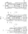
- Embodiment 1 1A to 1C show the structure and operating procedure of a three-component mixing container.
- FIG. 1D shows details of some of the diagrams of FIG. 1A.
- the main body A (2) and the main body B (3) have an in-row structure, and can be slid in the axial direction (dashed line in the figure).
- FIG. 1D shows an ⁇ view and a ⁇ - ⁇ cross section in (a) of FIG. 1A.
- the stopper 13 is provided on the side surface of the main body B (3), and is fitted into and fixed to the hole 12 provided in the main body A (2).
- the hole portion 12 has a notch portion 7, and the notch portion 7 reduces the rigidity around the hole portion 12 of the main body A (2), so that the stopper 13 is attached to the hole portion 12. It is easy to insert.
- the hole 12 is composed of an upper positioning hole 8, a middle positioning hole 9, and a lower positioning hole 10.
- the width of each hole end is small, and the stopper 13 passes through each hole end. When doing, it receives resistance and moves. This resistance prevents unintentional movement from one positioning hole to another positioning hole, and the stopper 13 has the above three positions (upper position, middle position, lower position). (Position).
- there is an opening 11 in the ⁇ - ⁇ cross section there is an opening 11 in the ⁇ - ⁇ cross section, and the sample that has entered from above the mixing container passes through this opening 11 and flows downward in the mixing container.
- FIG. 1A (a) when the main body B (3) is moved to the above-described upper positioning hole 8 and the sample 1 (4) is poured from the main body B (3), the sample 1 (4) becomes an arrow in the figure. As shown by the solid line with the mark, the sample 1 (4) is accumulated in the space formed by the bottom 1 and the main body A (2) through each opening. After the sample 1 (4) is poured into the required amount, as shown in FIG. 1A (b), the main body B (3) is moved to the middle positioning hole 9, and the sample 1 (4) is inserted. Block the opening entrance of the space. In this state, when the sample 2 (5) is poured from the main body B (3), it accumulates in a space formed by the main body A (2) and the main body B (3).
- FIG. 1B (a) when a required amount of sample 3 (6) is dispensed into the main body B (3), it collects in the space formed by the main body A (2) and the main body B (3). Thereafter, as shown in FIG. 1B (b), the cap portion 14 is screwed into the main body B (3) to close the space formed by the main body A (2) and the main body B (3). In this state, as shown in FIG. 1B (c), when the main body B (3) is slid to the upper position, the sample 2 (5) and the sample 3 (6) are collected, and the sample 1 (4) is accumulated. The sample 20 is obtained by mixing the three samples.
- FIG. 1C (a) when the mixing container 33 is turned upside down, the mixed sample 20 flows into the main body B (3).
- FIG. 1C (b) when the cap 17 of the cap portion 14 is opened and the bottom 1 is pushed in the direction of the arrow, a part 21 of the mixed sample 20 is poured into the spout 18 of the cap portion 14. Extruded from.
- the bottom 1 comes out of a flexible material (for example, silicon rubber) that can be deformed, and as shown in FIG. 1C (b), the bottom 1 is pushed in the direction of the arrow, thereby mixing the container. Since it is recessed inside 33, the gas in the mixing container is compressed, and the mixed sample 20 can be discharged from the spout 18.
- a flexible material for example, silicon rubber
- the main bodies A and B constituting the mixing container 33 described above are materials that satisfy chemical resistance, particularly strong resistance to strong alkaline aqueous solution, excellent moldability, and the like, and are inexpensive materials. Is required. Therefore, PP (polypropylene) is used in the present embodiment.
- the main bodies A and B are each formed by injection molding. Assemble body B into body A by press fitting.
- the size of the mixing container 33 is preferably a palm size. The reason is that the mixing container 33 is held and operated. If it is too large, the amount of liquid to be mixed increases, and it becomes necessary to prepare a larger amount than the desired mixing amount. This is because the amount to be used increases and waste occurs.
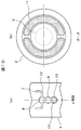
- FIG. 2 is a view showing a lock mechanism for preventing sample leakage.
- the main body A (2) and the main body B (3) do not slide because the catch portion 25 of the main body A (2) is engaged with the convex portion 24 of the main body B (3). It is locked to.
- FIG. 2 (b) when the cap portion 14 is screwed into the main body A (2), the wedge portion 23 of the cap portion 14 becomes the hook portion 25 and the main body B of the main body A (2). (3) bite into the convex part 24, the hook part 25 of the main body A (2) comes off from the convex part 24 of the main body B (3), and the lock is released.
- the lock is released, as shown in FIG. 2C, the main body B (3) can be slid to the upper position, and the sample 2 (5) and the sample 3 (6) become the sample 1. (4)
- the sample 20 which flows into the side and mixed is made.
- FIG. 3 is a diagram showing a scale for adjusting the amount of the sample.
- (A) is sectional drawing of a mixing container,
- (b) shows the figure which expanded the scale when it sees from (gamma) position shown by (a). It is the figure which showed the scale 27 for adjusting the quantity which puts the sample 3 (6) into the main body B (3).
- the main body B (3) is made of a transparent material, and the sample 3 (6) can be confirmed from the outside of the main body B (3).
- the main body B (3) is provided with a scale 27 as shown by an arrow ⁇ in FIG. 3, and the amount of the sample 3 (6) poured can be adjusted according to the scale.
- the scale 27 may be easily understood by changing the color.
- FIG. 4 is a diagram showing the jig 28 when the mixing container 33 is used.
- the main body A (2) is inserted into the groove of the jig 28 with the error portion 29 provided on the main body A (2), thereby allowing the container 33 to stand up.
- the jig 28 is fixed to the floor surface and can be held so as not to move even if force is applied to the container 33. By doing so, the cap portion 14 can be screwed into the main body B (3) without having the main body A (2) or the main body B (3).
- the mixing container shown in Embodiment 1 has a structure capable of mixing three liquids, but two liquids can also be mixed. Since the mixed liquid is usually sufficient if two or three liquids can be mixed, the mixing container having this structure is versatile.
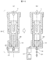
- Embodiment 2 >> 5A and 5B are structural diagrams and operation flows of another embodiment of the present invention.
- the main structural differences from FIGS. 1A to 1D shown in Embodiment 1 are that the space for inserting the sample 2 (5) is omitted, and the two samples of only the sample 1 (4) and the sample 3 (6) are omitted. Is to be mixed. Further, as shown in the ⁇ view of FIG. 5B, since only two samples are mixed, the stopper 13 only needs to be located at two positions, the upper positioning hole 8 and the lower positioning hole 10.
- the body B (3) is slid to the lower position to close the space in which the sample 1 (4) is placed.
- the sample 1 (4) is held in the container 33.
- the sample 3 (6) is poured into the space formed by the main body B (3) and the main body A (2), and the cap portion 14 is screwed into the main body A (2). The space containing the sample 3 (6) is closed.
- the mixing container shown in Embodiment 2 is characterized by a simple structure, and has an advantage in terms of manufacturing cost. Therefore, when mixing two liquids, the container of this structure can be used. Although omitted in FIG. 5A, a lock mechanism for preventing sample leakage similar to FIG. 2 may be provided.
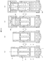
- FIG. 6 is a diagram showing an outline of the entire apparatus system using the mixing container 33 of the present invention.
- a part 21 of the sample mixed from the mixing container 33 is put into a sample cup 35 fixed to a tray 34 provided with a hole 31.
- the measurement container 39 is lowered with respect to the sample cup 35, and the holding arm 37 is hooked on the protruding portion of the sample cup 35 and held.
- the measurement container 39 is provided with a handle 38 for facilitating holding and a nozzle 36 for introducing vaporized gas generated from the sample in the sample bottle 35 into the analyzer 40. Although not shown, the nozzle 36 and the sample cup 35 are connected inside the measurement container 39.
- the measurement container 39 is set in the sample introduction unit 42 of the analyzer 40. After the setting, the sample gas vaporized in the sample cup 35 is introduced into the analyzer 40 and the components of the part 22 of the mixed sample are analyzed, and the analysis result is displayed on the operation panel 41.
- this invention is not limited to an above-described Example, Various modifications are included.
Landscapes
- Health & Medical Sciences (AREA)
- Chemical & Material Sciences (AREA)
- Analytical Chemistry (AREA)
- General Health & Medical Sciences (AREA)
- Hematology (AREA)
- Clinical Laboratory Science (AREA)
- Chemical Kinetics & Catalysis (AREA)
- Physics & Mathematics (AREA)
- Life Sciences & Earth Sciences (AREA)
- Biochemistry (AREA)
- General Physics & Mathematics (AREA)
- Immunology (AREA)
- Pathology (AREA)
- Package Specialized In Special Use (AREA)
Abstract
Provided is a vessel with which two or more kinds of liquid, powdered or granular samples can be mixed safely, easily, quickly, and reliably without contamination and the mixed sample can be easily removed. The mixing vessel is characterized in: being formed from two or more parts and having spaces in two or more chambers for storing the two or more kinds of samples; and two parts being configured so as to be capable of sliding in the axial direction and of achieving, as a result of a change in the relative position of the two parts, a state in which the two or more kinds of different samples are stored separately and a state in which the two or more kinds of different samples that have been stored are mixed.
Description
本発明は、異なる2種類以上の試料を混合する混合容器、及びそれを用いた分析装置に関する。
The present invention relates to a mixing container for mixing two or more different types of samples, and an analysis apparatus using the mixing container.
可搬型の分析装置は様々な場所で使用することができるが、分析する試料を準備する作業もその場所で実施する必要がある。例えば、液体試料では、分析性能を向上させるためアルカリ水溶液を混合したり、分析装置の校正を行うための内標物質を混合したりすることがある。このような試料を準備する作業を、作業者に負担なく、試料汚染の発生が無くなく、安全、簡単、迅速に実施できることが望まれている。
¡Portable analyzers can be used in various places, but the work for preparing samples to be analyzed must also be performed in those places. For example, in a liquid sample, an alkaline aqueous solution may be mixed in order to improve analytical performance, or an internal standard substance for calibrating the analyzer may be mixed. It is desired that the operation of preparing such a sample can be performed safely, easily and quickly without burdening the operator and without causing sample contamination.
その一例として、例えば、特許文献1には、キャップを回転させることで、上下部カッターが2種類の薬剤を分離、保管しているアルミシールを切断して、2種類の薬剤を混合させる構造が記載されている。
As an example, for example, Patent Document 1 discloses a structure in which a cap is rotated so that an upper and lower cutter separates two kinds of medicines and cuts an aluminum seal that is stored to mix the two kinds of medicines. Are listed.
上記従来の方法は、切断後のアルミシールが障害物となって2種類の薬剤の混合が十分に行えないという問題や、混合液の滴下が困難となるという課題がある。
The above-mentioned conventional methods have a problem that the aluminum seal after cutting becomes an obstacle and the mixing of the two kinds of chemicals cannot be sufficiently performed, and there is a problem that it is difficult to drop the mixed solution.
そこで、本発明は上記課題を解決するために、2種類以上の液体または粉末状の試料を、安全、簡単、迅速、汚染なく、確実に混合でき、更に、混合した試料の取り出しが容易に行える混合容器を提供することを目的とする。
Therefore, in order to solve the above problems, the present invention can reliably mix two or more kinds of liquid or powdered samples safely, simply, quickly, without contamination, and can easily take out the mixed samples. An object is to provide a mixing container.
上記課題を解決するために、本発明の混合容器の主な特徴は以下の通りである。
すなわち、本発明の混合容器は、2つ以上の部品で構成され、2種類以上の異なる試料を保管する2室以上の空間を有している。2つ以上の部品は軸方向にスライドできる構造となっており、スライドさせて部品間の相対位置変化させることにより、2種類以上の異なる試料を個別に保管する状態と、保管された2種類以上の異なる試料が混ざり合う状態を実現できる構造となっていることを特徴とする。 In order to solve the above problems, the main features of the mixing container of the present invention are as follows.
That is, the mixing container of the present invention is composed of two or more parts, and has two or more spaces for storing two or more different samples. Two or more parts are structured to be slidable in the axial direction, and by sliding and changing the relative position between the parts, two or more different samples are stored individually, and two or more stored types It is characterized by having a structure capable of realizing a state in which samples of different sizes are mixed.
また、別の部品で構成されるキャップ部を開けて、混合容器の一部を変形させて体積を変化させることによって、キャップ部から混合した試料を簡単に取り出すことができることを特徴としている。
Further, it is characterized in that a sample mixed from the cap part can be easily taken out by opening a cap part constituted by another part and changing a volume by deforming a part of the mixing container.
更に、スライド部にはロック機構が設けてあり、キャップ部を取り付けた状態でないと、保管された2種類以上の異なる試料が混ざり合う状態にスライドさせることができず、混合容器の外部への試料の漏洩、流出を防止できる構造となっていることを特徴とする。
Furthermore, the slide part is provided with a lock mechanism, and if the cap part is not attached, the stored sample cannot be slid into a state where two or more different kinds of samples are mixed, and the sample to the outside of the mixing container It has a structure that can prevent leakage and outflow.
本発明により、2種類以上の液体または粉末状、粒子状の試料を、安全、簡単、迅速、汚染なく、確実に混合でき、混合した試料を容易に取りだせる混合容器を提供することが可能になる。
According to the present invention, it is possible to provide a mixing container in which two or more kinds of liquid or powdered and particulate samples can be mixed safely, easily, quickly, and without contamination, and the mixed sample can be easily taken out. Become.
以下に、図面を用いて本発明の実施形態を説明する。
≪実施形態1≫
図1A~図1Cは、3液混合容器の構造と操作手順を示している。図1Dは、図1Aの一部の図象の詳細を示している。 Embodiments of the present invention will be described below with reference to the drawings.
Embodiment 1
1A to 1C show the structure and operating procedure of a three-component mixing container. FIG. 1D shows details of some of the diagrams of FIG. 1A.
≪実施形態1≫
図1A~図1Cは、3液混合容器の構造と操作手順を示している。図1Dは、図1Aの一部の図象の詳細を示している。 Embodiments of the present invention will be described below with reference to the drawings.
1A to 1C show the structure and operating procedure of a three-component mixing container. FIG. 1D shows details of some of the diagrams of FIG. 1A.
まず、図1Aに示すように、本体A(2)と本体B(3)とは、インロウ構造となっており、かつ、軸方向(図中の一点鎖線)にスライドできる構造となっている。図1Aの(a)中のα視図、および、β-β断面を図1Dに示す。ストッパー13は、本体B(3)の側面に設けられ、本体A(2)に設けられた穴部12に嵌められて固定される。
First, as shown in FIG. 1A, the main body A (2) and the main body B (3) have an in-row structure, and can be slid in the axial direction (dashed line in the figure). FIG. 1D shows an α view and a β-β cross section in (a) of FIG. 1A. The stopper 13 is provided on the side surface of the main body B (3), and is fitted into and fixed to the hole 12 provided in the main body A (2).
図1Dに示すように、穴部12には、切り欠き部7があり、この切り欠き部7により本体A(2)の穴部12周辺の剛性を低下させて、ストッパー13を穴部12に挿入しやすくしている。穴部12は、上位置決め用穴8、中位置決め用穴9、下位置決め用穴10の3つで構成され、各穴端部の幅は小さくなっており、スットパー13が各穴端部を通過する際は抵抗力を受け移動する。この抵抗力があることにより、一の位置決め用穴から他の位置決め用穴へ意図せずに移動してしまうことを抑制し、ストッパー13は、上記の3つの位置(上位置、中間位置、下位置)で停止する構造となっている。図1Dに示すようにβ-β断面に開口部11があり、混合容器の上方から侵入した試料はこの開口部11を通過し、混合容器の下方へ流れる。
As shown in FIG. 1D, the hole portion 12 has a notch portion 7, and the notch portion 7 reduces the rigidity around the hole portion 12 of the main body A (2), so that the stopper 13 is attached to the hole portion 12. It is easy to insert. The hole 12 is composed of an upper positioning hole 8, a middle positioning hole 9, and a lower positioning hole 10. The width of each hole end is small, and the stopper 13 passes through each hole end. When doing, it receives resistance and moves. This resistance prevents unintentional movement from one positioning hole to another positioning hole, and the stopper 13 has the above three positions (upper position, middle position, lower position). (Position). As shown in FIG. 1D, there is an opening 11 in the β-β cross section, and the sample that has entered from above the mixing container passes through this opening 11 and flows downward in the mixing container.
図1Aの(a)において、本体B(3)を上述した上位置決め用穴8に移動させ、本体B(3)から試料1(4)を注ぐと、試料1(4)は図中の矢印を付した実線で示すように各開口部を伝って、試料1(4)がボトム1と本体A(2)が成す空間に溜まる。試料1(4)を必要量分、流し入れて終わった後に、図1Aの(b)に示すように、本体B(3)を中位置決め用穴9に移動させ、試料1(4)が入っている空間の開口部入口を塞ぐ。この状態で、本体B(3)から試料2(5)を注ぐと、本体A(2)と本体B(3)が成す空間に溜まる。
In FIG. 1A (a), when the main body B (3) is moved to the above-described upper positioning hole 8 and the sample 1 (4) is poured from the main body B (3), the sample 1 (4) becomes an arrow in the figure. As shown by the solid line with the mark, the sample 1 (4) is accumulated in the space formed by the bottom 1 and the main body A (2) through each opening. After the sample 1 (4) is poured into the required amount, as shown in FIG. 1A (b), the main body B (3) is moved to the middle positioning hole 9, and the sample 1 (4) is inserted. Block the opening entrance of the space. In this state, when the sample 2 (5) is poured from the main body B (3), it accumulates in a space formed by the main body A (2) and the main body B (3).
更に、図1Aの(c)に示すように、本体B(3)を下位置決め用穴10に移動させると、試料2(5)が溜まった空間の開口部入口が塞がれる。この状態を維持すれば、試料1(4)と試料2(5)が混ざり合うことも、容器外に出ることもなく、保持することができる。
Further, as shown in FIG. 1A (c), when the main body B (3) is moved to the lower positioning hole 10, the opening entrance of the space where the sample 2 (5) is accumulated is blocked. If this state is maintained, the sample 1 (4) and the sample 2 (5) can be held without being mixed or coming out of the container.
図1Bの(a)において、本体B(3)に試料3(6)を必要量分注ぐと、本体A(2)と本体B(3)が成す空間に溜まる。その後、図1Bの(b)に示したように、キャップ部14を本体B(3)にネジ込んで本体A(2)と本体B(3)が成す空間を塞ぐ。この状態で、図1Bの(c)に示したように、本体B(3)を上位置にスライドさせると、試料2(5)と試料3(6)が、試料1(4)が溜まっている空間に流れ込み、3つの試料が混合された試料20ができる。
In FIG. 1B (a), when a required amount of sample 3 (6) is dispensed into the main body B (3), it collects in the space formed by the main body A (2) and the main body B (3). Thereafter, as shown in FIG. 1B (b), the cap portion 14 is screwed into the main body B (3) to close the space formed by the main body A (2) and the main body B (3). In this state, as shown in FIG. 1B (c), when the main body B (3) is slid to the upper position, the sample 2 (5) and the sample 3 (6) are collected, and the sample 1 (4) is accumulated. The sample 20 is obtained by mixing the three samples.
図1Cの(a)のように、混合容器33を上下反転させると、混合された試料20が本体B(3)に流れ込む。この状態で、図1Cの(b)のように、キャップ部14のキャップ17を開けて、ボトム1を矢印方向に押すと、混合された試料20の一部21がキャップ部14の注ぎ口18から押し出される。
As shown in FIG. 1C (a), when the mixing container 33 is turned upside down, the mixed sample 20 flows into the main body B (3). In this state, as shown in FIG. 1C (b), when the cap 17 of the cap portion 14 is opened and the bottom 1 is pushed in the direction of the arrow, a part 21 of the mixed sample 20 is poured into the spout 18 of the cap portion 14. Extruded from.
ここで、ボトム1は、変形させることができる柔軟な素材(例えば、シリコンゴム)で出きており、図1Cの(b)に示すように、ボトム1を矢印方向に押すことで、混合容器33の内側へ凹むので、混合容器内の気体は圧縮され、混合された試料20を注ぎ口18から出すことができる。
Here, the bottom 1 comes out of a flexible material (for example, silicon rubber) that can be deformed, and as shown in FIG. 1C (b), the bottom 1 is pushed in the direction of the arrow, thereby mixing the container. Since it is recessed inside 33, the gas in the mixing container is compressed, and the mixed sample 20 can be discharged from the spout 18.
なお、上述した混合容器33を構成する本体A及びBは、耐薬品性、特に強アルカリ水溶液に耐性が強いこと、成形性に優れることなどを満たす材質であり、さらに、安価な材料であることが要求される。そこで、本実施形態では、PP(ポリプレピレン)を用いている。また、本体A及びBは、それぞれ射出成型を用いて形成している。本体Aに本体Bを圧入して組み立てる。
The main bodies A and B constituting the mixing container 33 described above are materials that satisfy chemical resistance, particularly strong resistance to strong alkaline aqueous solution, excellent moldability, and the like, and are inexpensive materials. Is required. Therefore, PP (polypropylene) is used in the present embodiment. The main bodies A and B are each formed by injection molding. Assemble body B into body A by press fitting.
混合容器33の大きさは、手のひらサイズが好ましい。その理由は、混合容器33は手に持って操作するからであり、大きすぎると、混合する液の量が多くなり、所望の混合量より多くの量を用意する必要が生じるため、分析後に廃棄する量が多くなり無駄が生じるためである。
The size of the mixing container 33 is preferably a palm size. The reason is that the mixing container 33 is held and operated. If it is too large, the amount of liquid to be mixed increases, and it becomes necessary to prepare a larger amount than the desired mixing amount. This is because the amount to be used increases and waste occurs.
図2は、試料漏洩防止のロック機構を示す図である。
図2の(a)に示したように、本体B(3)の凸部24に本体A(2)の引っ掛かり部25がかみ合って、本体A(2)と本体B(3)がスライドしないようにロックされている。この状態で、図2の(b)に示したように、キャップ部14を本体A(2)にねじ込むと、キャップ部14のくさび部23が、本体A(2)の引っ掛かり部25と本体B(3)の凸部24との間に食い込み、本体A(2)の引っ掛かり部25が本体B(3)の凸部24から外れ、ロックが解除される。ロックが解除された状態になると、図2の(c)に示したように、本体B(3)を上位置にスライドさせることができ、試料2(5)と試料3(6)が試料1(4)側に流入し、混合された試料20ができる。 FIG. 2 is a view showing a lock mechanism for preventing sample leakage.
As shown in FIG. 2 (a), the main body A (2) and the main body B (3) do not slide because thecatch portion 25 of the main body A (2) is engaged with the convex portion 24 of the main body B (3). It is locked to. In this state, as shown in FIG. 2 (b), when the cap portion 14 is screwed into the main body A (2), the wedge portion 23 of the cap portion 14 becomes the hook portion 25 and the main body B of the main body A (2). (3) bite into the convex part 24, the hook part 25 of the main body A (2) comes off from the convex part 24 of the main body B (3), and the lock is released. When the lock is released, as shown in FIG. 2C, the main body B (3) can be slid to the upper position, and the sample 2 (5) and the sample 3 (6) become the sample 1. (4) The sample 20 which flows into the side and mixed is made.
図2の(a)に示したように、本体B(3)の凸部24に本体A(2)の引っ掛かり部25がかみ合って、本体A(2)と本体B(3)がスライドしないようにロックされている。この状態で、図2の(b)に示したように、キャップ部14を本体A(2)にねじ込むと、キャップ部14のくさび部23が、本体A(2)の引っ掛かり部25と本体B(3)の凸部24との間に食い込み、本体A(2)の引っ掛かり部25が本体B(3)の凸部24から外れ、ロックが解除される。ロックが解除された状態になると、図2の(c)に示したように、本体B(3)を上位置にスライドさせることができ、試料2(5)と試料3(6)が試料1(4)側に流入し、混合された試料20ができる。 FIG. 2 is a view showing a lock mechanism for preventing sample leakage.
As shown in FIG. 2 (a), the main body A (2) and the main body B (3) do not slide because the
この構造により、キャップ部14が本体A(2)にねじ込まれない限り、本体A(2)と本体B(3)をスライドさせることができないため、試料1(4)と試料2(5)が混合されたり、容器33の外に漏れたりすることを防止することができる。
With this structure, since the main body A (2) and the main body B (3) cannot be slid unless the cap portion 14 is screwed into the main body A (2), the sample 1 (4) and the sample 2 (5) Mixing or leakage outside the container 33 can be prevented.
図3は、試料の量を調整するための目盛を示す図である。(a)は、混合容器の断面図であり、(b)は、(a)で示すγ位置から見たときの目盛を拡大した図を示す。試料3(6)を本体B(3)に入れる量を調整するための目盛27を示した図である。ここで、本体B(3)は透明な素材でできており、試料3(6)が本体B(3)の外側から確認できる。本体B(3)には図3の矢視図γのように目盛27が設けられており、試料3(6)を注ぐ量を目盛に合わせて調整できる。目盛27は色を変えて判り易くしても良い。
FIG. 3 is a diagram showing a scale for adjusting the amount of the sample. (A) is sectional drawing of a mixing container, (b) shows the figure which expanded the scale when it sees from (gamma) position shown by (a). It is the figure which showed the scale 27 for adjusting the quantity which puts the sample 3 (6) into the main body B (3). Here, the main body B (3) is made of a transparent material, and the sample 3 (6) can be confirmed from the outside of the main body B (3). The main body B (3) is provided with a scale 27 as shown by an arrow γ in FIG. 3, and the amount of the sample 3 (6) poured can be adjusted according to the scale. The scale 27 may be easily understood by changing the color.
図4は、混合容器33を使用する際の治具28を示す図である。
図4に示したように、本体A(2)を、本体A(2)に設けられたエラ部29を治具28の溝に合わせて差し込み、容器33を自立させる。治具28には床面に固定されており、容器33に力が加わっても動かないように保持できる。こうすることで、本体A(2)または本体B(3)を持たなくて、本体B(3)にキャップ部14をネジ込むことができる。 FIG. 4 is a diagram showing thejig 28 when the mixing container 33 is used.
As shown in FIG. 4, the main body A (2) is inserted into the groove of thejig 28 with the error portion 29 provided on the main body A (2), thereby allowing the container 33 to stand up. The jig 28 is fixed to the floor surface and can be held so as not to move even if force is applied to the container 33. By doing so, the cap portion 14 can be screwed into the main body B (3) without having the main body A (2) or the main body B (3).
図4に示したように、本体A(2)を、本体A(2)に設けられたエラ部29を治具28の溝に合わせて差し込み、容器33を自立させる。治具28には床面に固定されており、容器33に力が加わっても動かないように保持できる。こうすることで、本体A(2)または本体B(3)を持たなくて、本体B(3)にキャップ部14をネジ込むことができる。 FIG. 4 is a diagram showing the
As shown in FIG. 4, the main body A (2) is inserted into the groove of the
実施形態1で示した混合容器は、3液を混合できる構造となっているが、2液の混合も可能である。混合液は、通常、2又は3液が混合できれば十分であるので、本構造を有する混合容器は汎用性がある。
The mixing container shown in Embodiment 1 has a structure capable of mixing three liquids, but two liquids can also be mixed. Since the mixed liquid is usually sufficient if two or three liquids can be mixed, the mixing container having this structure is versatile.
≪実施形態2≫
図5A、5Bは、本発明の別の実施形態の構造図、動作フローを示す図である。
実施形態1で示す図1A~1Dとの主な構造上の相違点は、試料2(5)を入れる空間が省略されていて、試料1(4)と試料3(6)だけの2つの試料が混合されることである。また、図5Bのγ視図に示したように、2つの試料を混合するだけなので、ストッパー13の位置も上位置決め用穴8と下位置決め用穴10の2ヶ所だけでよい。 <<Embodiment 2 >>
5A and 5B are structural diagrams and operation flows of another embodiment of the present invention.
The main structural differences from FIGS. 1A to 1D shown inEmbodiment 1 are that the space for inserting the sample 2 (5) is omitted, and the two samples of only the sample 1 (4) and the sample 3 (6) are omitted. Is to be mixed. Further, as shown in the γ view of FIG. 5B, since only two samples are mixed, the stopper 13 only needs to be located at two positions, the upper positioning hole 8 and the lower positioning hole 10.
図5A、5Bは、本発明の別の実施形態の構造図、動作フローを示す図である。
実施形態1で示す図1A~1Dとの主な構造上の相違点は、試料2(5)を入れる空間が省略されていて、試料1(4)と試料3(6)だけの2つの試料が混合されることである。また、図5Bのγ視図に示したように、2つの試料を混合するだけなので、ストッパー13の位置も上位置決め用穴8と下位置決め用穴10の2ヶ所だけでよい。 <<
5A and 5B are structural diagrams and operation flows of another embodiment of the present invention.
The main structural differences from FIGS. 1A to 1D shown in
先ず、図5Aの(a)に示したように、本体B(3)を上位置にスライドさせ、試料1を注ぐと、ボトム1と本体A(2)が成す空間に試料1(4)が溜まる。
First, as shown in FIG. 5A (a), when the main body B (3) is slid to the upper position and the sample 1 is poured, the sample 1 (4) is placed in the space formed by the bottom 1 and the main body A (2). Accumulate.
次に、図5Aの(b)に示したように、本体B(3)を下位置にスライドさせ、試料1(4)を入れた空間を塞ぐ。この状態で試料1(4)を容器33内に保持する。また、図5Aの(c)に示したように、試料3(6)を本体B(3)と本体A(2)が成す空間に注ぎ、キャップ部14を本体A(2)にネジ込み、試料3(6)を入れた空間を塞ぐ。
Next, as shown in FIG. 5A (b), the body B (3) is slid to the lower position to close the space in which the sample 1 (4) is placed. In this state, the sample 1 (4) is held in the container 33. Also, as shown in FIG. 5A (c), the sample 3 (6) is poured into the space formed by the main body B (3) and the main body A (2), and the cap portion 14 is screwed into the main body A (2). The space containing the sample 3 (6) is closed.
次に、5Aの(d)に示したように、本体B(3)を上位置にスライドさせると、試料3(6)が試料1(4)と同じ空間に流れ込み、混合された試料20ができる。
Next, as shown in (d) of 5A, when the main body B (3) is slid to the upper position, the sample 3 (6) flows into the same space as the sample 1 (4), and the mixed sample 20 is it can.
実施形態2で示した混合容器は、構造がシンプルである点が特徴であり、製造コスト面で有利な点を有する。従って、2液混合する場合は、本構造の容器を用いることができる。
なお、図5Aでは省略したが、図2と同じような試料漏洩防止のロック機構を設けても良い。 The mixing container shown inEmbodiment 2 is characterized by a simple structure, and has an advantage in terms of manufacturing cost. Therefore, when mixing two liquids, the container of this structure can be used.
Although omitted in FIG. 5A, a lock mechanism for preventing sample leakage similar to FIG. 2 may be provided.
なお、図5Aでは省略したが、図2と同じような試料漏洩防止のロック機構を設けても良い。 The mixing container shown in
Although omitted in FIG. 5A, a lock mechanism for preventing sample leakage similar to FIG. 2 may be provided.
≪実施形態3≫
図6は、本発明の混合容器33を用いた装置システムの全体の概略を示す図である。
穴部31を設けたトレー34に固定した試料カップ35に混合容器33から混合された試料の一部21を入れる。測定容器39を試料カップ35に対して、下降させ、保持腕37を試料カップ35の出っ張り部にひっかけ、保持する。 <<Embodiment 3 >>
FIG. 6 is a diagram showing an outline of the entire apparatus system using the mixingcontainer 33 of the present invention.
Apart 21 of the sample mixed from the mixing container 33 is put into a sample cup 35 fixed to a tray 34 provided with a hole 31. The measurement container 39 is lowered with respect to the sample cup 35, and the holding arm 37 is hooked on the protruding portion of the sample cup 35 and held.
図6は、本発明の混合容器33を用いた装置システムの全体の概略を示す図である。
穴部31を設けたトレー34に固定した試料カップ35に混合容器33から混合された試料の一部21を入れる。測定容器39を試料カップ35に対して、下降させ、保持腕37を試料カップ35の出っ張り部にひっかけ、保持する。 <<
FIG. 6 is a diagram showing an outline of the entire apparatus system using the mixing
A
この際、図示していないOリングが潰れ、測定容器39と試料カップ35との機密性は保たれる。測定容器39には、持ちやすくするための取っ手38と試料ビン35内の試料から発生した気化ガスを分析装置40内に導入するためのノズル36が付いている。ノズル36と試料カップ35間は図示していないが、測定容器39の内部でつながっている。測定容器39を分析装置40の試料導入ユニット42にセットする。セット後、試料カップ35に気化した試料ガスが分析装置40内に導入され混合された試料の一部22の成分を分析し、分析結果が操作パネル41に表示される。
なお、本発明は上記した実施例に限定されるものではなく、様々な変形例が含まれる。 At this time, an O-ring (not shown) is crushed, and confidentiality between themeasurement container 39 and the sample cup 35 is maintained. The measurement container 39 is provided with a handle 38 for facilitating holding and a nozzle 36 for introducing vaporized gas generated from the sample in the sample bottle 35 into the analyzer 40. Although not shown, the nozzle 36 and the sample cup 35 are connected inside the measurement container 39. The measurement container 39 is set in the sample introduction unit 42 of the analyzer 40. After the setting, the sample gas vaporized in the sample cup 35 is introduced into the analyzer 40 and the components of the part 22 of the mixed sample are analyzed, and the analysis result is displayed on the operation panel 41.
In addition, this invention is not limited to an above-described Example, Various modifications are included.
なお、本発明は上記した実施例に限定されるものではなく、様々な変形例が含まれる。 At this time, an O-ring (not shown) is crushed, and confidentiality between the
In addition, this invention is not limited to an above-described Example, Various modifications are included.
1:ボトム、
2:本体A、
3:本体B、
4:試料1、
5:試料2、
6:試料3、
7:切り欠き部、
8:上位置決め用穴、
9:中位置決め用穴、
10:下位置決め用穴、
11:開口部、
12:穴部、
13:ストッパー、
14:キャップ部、
15:ネジ部、
16:ジョイント、
17:キャップ、
18:注ぎ口、
19:シール部、
20:混合された試料、
21:混合された試料の一部、
23:くさび部、
24:凸部、
25:引っ掛かり部、
27:目盛、
28:治具、
29:エラ部、
31:穴部、
33:混合容器、
34:トレー、
35:試料カップ、
36:ノズル、
37:保持腕、
38:取っ手、
39:測定容器、
40:分析装置、
41:操作パネル、
42:試料導入ユニット。 1: Bottom,
2: Body A,
3: Body B,
4:Sample 1,
5:Sample 2,
6:Sample 3,
7: Notch,
8: Upper positioning hole,
9: Hole for middle positioning,
10: Lower positioning hole,
11: opening,
12: hole,
13: Stopper
14: Cap part,
15: Screw part,
16: Joint,
17: Cap,
18: Spout,
19: seal part,
20: mixed sample,
21: part of the mixed sample,
23: Wedge part,
24: convex part,
25: hook part,
27: Scale,
28: jig,
29: Ella,
31: hole,
33: mixing container,
34: Tray,
35: Sample cup,
36: nozzle,
37: holding arm,
38: Handle,
39: Measuring container,
40: analyzer
41: Operation panel,
42: Sample introduction unit.
2:本体A、
3:本体B、
4:試料1、
5:試料2、
6:試料3、
7:切り欠き部、
8:上位置決め用穴、
9:中位置決め用穴、
10:下位置決め用穴、
11:開口部、
12:穴部、
13:ストッパー、
14:キャップ部、
15:ネジ部、
16:ジョイント、
17:キャップ、
18:注ぎ口、
19:シール部、
20:混合された試料、
21:混合された試料の一部、
23:くさび部、
24:凸部、
25:引っ掛かり部、
27:目盛、
28:治具、
29:エラ部、
31:穴部、
33:混合容器、
34:トレー、
35:試料カップ、
36:ノズル、
37:保持腕、
38:取っ手、
39:測定容器、
40:分析装置、
41:操作パネル、
42:試料導入ユニット。 1: Bottom,
2: Body A,
3: Body B,
4:
5:
6:
7: Notch,
8: Upper positioning hole,
9: Hole for middle positioning,
10: Lower positioning hole,
11: opening,
12: hole,
13: Stopper
14: Cap part,
15: Screw part,
16: Joint,
17: Cap,
18: Spout,
19: seal part,
20: mixed sample,
21: part of the mixed sample,
23: Wedge part,
24: convex part,
25: hook part,
27: Scale,
28: jig,
29: Ella,
31: hole,
33: mixing container,
34: Tray,
35: Sample cup,
36: nozzle,
37: holding arm,
38: Handle,
39: Measuring container,
40: analyzer
41: Operation panel,
42: Sample introduction unit.
Claims (7)
- 軸方向に互いにスライド可能な第1の筐体および第2の筐体を有し、
前記第1の筐体は、該筐体の外壁が前記第2の筐体の内壁に沿って前記軸方向にスライド可能であり、
前記第1の筐体を第1の所定位置にスライドさせることにより、2つ以上の試料を互いに個別に保管する複数の空間が形成された第1の状態と、
前記第1の筐体を第2の所定位置にスライドさせることにより、前記第1の状態の2つ以上の試料が互いに混ざり合う第2の状態とに変移可能な構造を有する
ことを特徴とする混合容器。 A first housing and a second housing that are slidable in the axial direction;
In the first casing, an outer wall of the casing is slidable in the axial direction along an inner wall of the second casing;
A first state in which a plurality of spaces for individually storing two or more samples are formed by sliding the first casing to a first predetermined position;
By sliding the first casing to a second predetermined position, the first casing has a structure that can be changed to a second state in which two or more samples in the first state are mixed with each other. Mixing container. - 前記第1及び第2の筐体は、上方から流動する試料を通過可能とする開口部を有する隔壁と、前記第1及び第2の筐体のスライドにより前記隔壁の開口部を密閉可能とする封止部とを有し、
前記第1及び第2の筐体をスライドすることにより、前記封止部を移動し前記開口部の開閉を行い、前記複数の空間の所望の空間への前記試料の注入及び保管を行う
ことを特徴とする請求項1に記載の混合容器。 The first and second casings allow the opening of the partition to be sealed by a partition having an opening that allows a sample flowing from above to pass therethrough, and the slide of the first and second casings. Having a sealing part,
Sliding the first and second housings to move the sealing part, open and close the opening, and inject and store the sample into a desired space of the plurality of spaces. The mixing container according to claim 1. - 前記第1及び第2の筐体をスライドすることにより、前記開口部のすべてを開放し、複数の空間内に個別に保管された2つ以上の試料を前記第2の筐体の下方の空間に移動し混合を行う
ことを特徴とする請求項1に記載の混合容器。 By sliding the first and second casings, all of the openings are opened, and two or more samples individually stored in a plurality of spaces are placed in a space below the second casing. The mixing container according to claim 1, wherein the mixing container is mixed. - 前記第1の筐体の前記試料の注入口を封止するキャップ部を有し、
前記キャップ部が下方に、前記第2の筐体の下方の空間が上方になるように回転することで、
前記第2の筐体の下方の空間で混合された混合試料の撹拌をさらに行う
ことを特徴とする請求項3に記載の混合容器。 A cap for sealing the sample inlet of the first housing;
By rotating so that the cap portion is downward and the space below the second housing is upward,
The mixing container according to claim 3, further comprising stirring the mixed sample mixed in a space below the second casing. - 前記第1の所定位置および第2の所定位置は、前記第1の筐体に設けられたストッパーが前記第2の筐体に設けられた穴形状部に保持されることで設定される
ことを特徴とする請求項1に記載の混合容器。 The first predetermined position and the second predetermined position are set by holding a stopper provided in the first casing in a hole-shaped portion provided in the second casing. The mixing container according to claim 1. - 前記第1の筐体の外壁に設けられた突起部と、前記第2の筐体の内壁に設けられた凹部とを有し、
前記突起部と前記凹部とが勘合することにより、前記第1の筐体と前記第2の筐体との相対位置の変化を抑制することで、前記空間に保管された試料の気密性が保たれ、外部への試料漏洩、流出を防止する
ことを特徴とする請求項1に記載の混合容器。 A projection provided on the outer wall of the first housing and a recess provided on the inner wall of the second housing;
By fitting the protrusion and the recess, the change in the relative position between the first housing and the second housing is suppressed, so that the airtightness of the sample stored in the space is maintained. 2. The mixing container according to claim 1, wherein the sample leaks and flows out to the outside. - 請求項1乃至6に記載のいずれかの混合容器を有し、
前記混合容器に保管された試料と他の分析対象である試料とを混合する試料カップと、
前記試料カップに取り付けた測定容器と、
前記測定容器を導入する試料導入ユニットと、を具備し、
前記試料カップで混合された混合液の分析を行うことを特徴とする分析装置。 A mixing container according to any one of claims 1 to 6,
A sample cup for mixing a sample stored in the mixing container with a sample to be analyzed, and
A measurement container attached to the sample cup;
A sample introduction unit for introducing the measurement container,
An analyzer for analyzing a mixed liquid mixed in the sample cup.
Priority Applications (1)
| Application Number | Priority Date | Filing Date | Title |
|---|---|---|---|
| JP2015522774A JPWO2014203761A1 (en) | 2013-06-20 | 2014-06-10 | Mixing container and analyzer using the same |
Applications Claiming Priority (2)
| Application Number | Priority Date | Filing Date | Title |
|---|---|---|---|
| JP2013-129821 | 2013-06-20 | ||
| JP2013129821 | 2013-06-20 |
Publications (1)
| Publication Number | Publication Date |
|---|---|
| WO2014203761A1 true WO2014203761A1 (en) | 2014-12-24 |
Family
ID=52104499
Family Applications (1)
| Application Number | Title | Priority Date | Filing Date |
|---|---|---|---|
| PCT/JP2014/065281 WO2014203761A1 (en) | 2013-06-20 | 2014-06-10 | Mixing vessel and analysis device using same |
Country Status (2)
| Country | Link |
|---|---|
| JP (1) | JPWO2014203761A1 (en) |
| WO (1) | WO2014203761A1 (en) |
Cited By (1)
| Publication number | Priority date | Publication date | Assignee | Title |
|---|---|---|---|---|
| CN105842041A (en) * | 2016-05-11 | 2016-08-10 | 张兆军 | Grain bin sample divider |
Citations (3)
| Publication number | Priority date | Publication date | Assignee | Title |
|---|---|---|---|---|
| JPH0465775U (en) * | 1990-10-18 | 1992-06-09 | ||
| JPH08500314A (en) * | 1992-08-20 | 1996-01-16 | ロレアル | A multi-compartment distributor for storing and mixing contents |
| JP2010023890A (en) * | 2008-07-22 | 2010-02-04 | Taisei Kako Co Ltd | Two-substance mixing container |
-
2014
- 2014-06-10 WO PCT/JP2014/065281 patent/WO2014203761A1/en active Application Filing
- 2014-06-10 JP JP2015522774A patent/JPWO2014203761A1/en active Pending
Patent Citations (3)
| Publication number | Priority date | Publication date | Assignee | Title |
|---|---|---|---|---|
| JPH0465775U (en) * | 1990-10-18 | 1992-06-09 | ||
| JPH08500314A (en) * | 1992-08-20 | 1996-01-16 | ロレアル | A multi-compartment distributor for storing and mixing contents |
| JP2010023890A (en) * | 2008-07-22 | 2010-02-04 | Taisei Kako Co Ltd | Two-substance mixing container |
Cited By (1)
| Publication number | Priority date | Publication date | Assignee | Title |
|---|---|---|---|---|
| CN105842041A (en) * | 2016-05-11 | 2016-08-10 | 张兆军 | Grain bin sample divider |
Also Published As
| Publication number | Publication date |
|---|---|
| JPWO2014203761A1 (en) | 2017-02-23 |
Similar Documents
| Publication | Publication Date | Title |
|---|---|---|
| EP2194385B1 (en) | Reagent container | |
| US7554658B2 (en) | Cuvette and cuvette cap | |
| KR101716740B1 (en) | Sample extracting, diluting and discharging device | |
| CN113905823B (en) | Device and method for aspirating and processing liquid samples and substances | |
| US20130205988A1 (en) | Piston and Cartridge Arrangement Having Said Piston | |
| WO2010122981A1 (en) | Container for mixing before use | |
| US9381480B2 (en) | Container for mixing two different types of solutions | |
| JP2008006431A (en) | Equilibration device | |
| US7681762B2 (en) | Device for storing and dispensing fluid substances | |
| KR101934819B1 (en) | Specimen container | |
| KR101800448B1 (en) | Sample-receiving device | |
| WO2014203761A1 (en) | Mixing vessel and analysis device using same | |
| CA2749777C (en) | Closure device for a reagent container | |
| KR20160073929A (en) | Mixing vessel | |
| JP2006321542A (en) | Mixing container | |
| JP2005313908A (en) | Reagent container | |
| JP2019164002A (en) | Stool container | |
| JP2009083879A (en) | Two-agent mixing container | |
| US20210086184A1 (en) | Container and method for activating reagents in such a container | |
| KR101934186B1 (en) | A specimen cup that can store and move the sample | |
| JP3929812B2 (en) | Fluid container | |
| JP5154172B2 (en) | Two-component mixing container | |
| US20110076206A1 (en) | Reagent containers for compact test devices | |
| US20230019192A1 (en) | Transportable sample drawing container, sample drawing system, and method for drawing a sample | |
| JP2004061470A (en) | Liquid storage container from which automatic pipetting is possible |
Legal Events
| Date | Code | Title | Description |
|---|---|---|---|
| 121 | Ep: the epo has been informed by wipo that ep was designated in this application |
Ref document number: 14813712 Country of ref document: EP Kind code of ref document: A1 |
|
| ENP | Entry into the national phase |
Ref document number: 2015522774 Country of ref document: JP Kind code of ref document: A |
|
| NENP | Non-entry into the national phase |
Ref country code: DE |
|
| 122 | Ep: pct application non-entry in european phase |
Ref document number: 14813712 Country of ref document: EP Kind code of ref document: A1 |