WO2014203591A1 - Solid fuel manufacturing method and manufacturing device - Google Patents
Solid fuel manufacturing method and manufacturing device Download PDFInfo
- Publication number
- WO2014203591A1 WO2014203591A1 PCT/JP2014/059767 JP2014059767W WO2014203591A1 WO 2014203591 A1 WO2014203591 A1 WO 2014203591A1 JP 2014059767 W JP2014059767 W JP 2014059767W WO 2014203591 A1 WO2014203591 A1 WO 2014203591A1
- Authority
- WO
- WIPO (PCT)
- Prior art keywords
- carrier gas
- porous coal
- amount
- slurry
- solid fuel
- Prior art date
Links
Images
Classifications
-
- C—CHEMISTRY; METALLURGY
- C10—PETROLEUM, GAS OR COKE INDUSTRIES; TECHNICAL GASES CONTAINING CARBON MONOXIDE; FUELS; LUBRICANTS; PEAT
- C10L—FUELS NOT OTHERWISE PROVIDED FOR; NATURAL GAS; SYNTHETIC NATURAL GAS OBTAINED BY PROCESSES NOT COVERED BY SUBCLASSES C10G, C10K; LIQUEFIED PETROLEUM GAS; ADDING MATERIALS TO FUELS OR FIRES TO REDUCE SMOKE OR UNDESIRABLE DEPOSITS OR TO FACILITATE SOOT REMOVAL; FIRELIGHTERS
- C10L5/00—Solid fuels
-
- C—CHEMISTRY; METALLURGY
- C10—PETROLEUM, GAS OR COKE INDUSTRIES; TECHNICAL GASES CONTAINING CARBON MONOXIDE; FUELS; LUBRICANTS; PEAT
- C10L—FUELS NOT OTHERWISE PROVIDED FOR; NATURAL GAS; SYNTHETIC NATURAL GAS OBTAINED BY PROCESSES NOT COVERED BY SUBCLASSES C10G, C10K; LIQUEFIED PETROLEUM GAS; ADDING MATERIALS TO FUELS OR FIRES TO REDUCE SMOKE OR UNDESIRABLE DEPOSITS OR TO FACILITATE SOOT REMOVAL; FIRELIGHTERS
- C10L9/00—Treating solid fuels to improve their combustion
- C10L9/10—Treating solid fuels to improve their combustion by using additives
-
- C—CHEMISTRY; METALLURGY
- C10—PETROLEUM, GAS OR COKE INDUSTRIES; TECHNICAL GASES CONTAINING CARBON MONOXIDE; FUELS; LUBRICANTS; PEAT
- C10L—FUELS NOT OTHERWISE PROVIDED FOR; NATURAL GAS; SYNTHETIC NATURAL GAS OBTAINED BY PROCESSES NOT COVERED BY SUBCLASSES C10G, C10K; LIQUEFIED PETROLEUM GAS; ADDING MATERIALS TO FUELS OR FIRES TO REDUCE SMOKE OR UNDESIRABLE DEPOSITS OR TO FACILITATE SOOT REMOVAL; FIRELIGHTERS
- C10L9/00—Treating solid fuels to improve their combustion
- C10L9/02—Treating solid fuels to improve their combustion by chemical means
-
- C—CHEMISTRY; METALLURGY
- C10—PETROLEUM, GAS OR COKE INDUSTRIES; TECHNICAL GASES CONTAINING CARBON MONOXIDE; FUELS; LUBRICANTS; PEAT
- C10L—FUELS NOT OTHERWISE PROVIDED FOR; NATURAL GAS; SYNTHETIC NATURAL GAS OBTAINED BY PROCESSES NOT COVERED BY SUBCLASSES C10G, C10K; LIQUEFIED PETROLEUM GAS; ADDING MATERIALS TO FUELS OR FIRES TO REDUCE SMOKE OR UNDESIRABLE DEPOSITS OR TO FACILITATE SOOT REMOVAL; FIRELIGHTERS
- C10L9/00—Treating solid fuels to improve their combustion
- C10L9/08—Treating solid fuels to improve their combustion by heat treatments, e.g. calcining
-
- F—MECHANICAL ENGINEERING; LIGHTING; HEATING; WEAPONS; BLASTING
- F26—DRYING
- F26B—DRYING SOLID MATERIALS OR OBJECTS BY REMOVING LIQUID THEREFROM
- F26B11/00—Machines or apparatus for drying solid materials or objects with movement which is non-progressive
- F26B11/02—Machines or apparatus for drying solid materials or objects with movement which is non-progressive in moving drums or other mainly-closed receptacles
- F26B11/04—Machines or apparatus for drying solid materials or objects with movement which is non-progressive in moving drums or other mainly-closed receptacles rotating about a horizontal or slightly-inclined axis
- F26B11/0463—Machines or apparatus for drying solid materials or objects with movement which is non-progressive in moving drums or other mainly-closed receptacles rotating about a horizontal or slightly-inclined axis having internal elements, e.g. which are being moved or rotated by means other than the rotating drum wall
- F26B11/0477—Machines or apparatus for drying solid materials or objects with movement which is non-progressive in moving drums or other mainly-closed receptacles rotating about a horizontal or slightly-inclined axis having internal elements, e.g. which are being moved or rotated by means other than the rotating drum wall for mixing, stirring or conveying the materials to be dried, e.g. mounted to the wall, rotating with the drum
-
- F—MECHANICAL ENGINEERING; LIGHTING; HEATING; WEAPONS; BLASTING
- F26—DRYING
- F26B—DRYING SOLID MATERIALS OR OBJECTS BY REMOVING LIQUID THEREFROM
- F26B21/00—Arrangements or duct systems, e.g. in combination with pallet boxes, for supplying and controlling air or gases for drying solid materials or objects
- F26B21/02—Circulating air or gases in closed cycles, e.g. wholly within the drying enclosure
- F26B21/04—Circulating air or gases in closed cycles, e.g. wholly within the drying enclosure partly outside the drying enclosure
-
- F—MECHANICAL ENGINEERING; LIGHTING; HEATING; WEAPONS; BLASTING
- F26—DRYING
- F26B—DRYING SOLID MATERIALS OR OBJECTS BY REMOVING LIQUID THEREFROM
- F26B21/00—Arrangements or duct systems, e.g. in combination with pallet boxes, for supplying and controlling air or gases for drying solid materials or objects
- F26B21/06—Controlling, e.g. regulating, parameters of gas supply
- F26B21/08—Humidity
-
- F—MECHANICAL ENGINEERING; LIGHTING; HEATING; WEAPONS; BLASTING
- F26—DRYING
- F26B—DRYING SOLID MATERIALS OR OBJECTS BY REMOVING LIQUID THEREFROM
- F26B23/00—Heating arrangements
- F26B23/02—Heating arrangements using combustion heating
-
- C—CHEMISTRY; METALLURGY
- C10—PETROLEUM, GAS OR COKE INDUSTRIES; TECHNICAL GASES CONTAINING CARBON MONOXIDE; FUELS; LUBRICANTS; PEAT
- C10L—FUELS NOT OTHERWISE PROVIDED FOR; NATURAL GAS; SYNTHETIC NATURAL GAS OBTAINED BY PROCESSES NOT COVERED BY SUBCLASSES C10G, C10K; LIQUEFIED PETROLEUM GAS; ADDING MATERIALS TO FUELS OR FIRES TO REDUCE SMOKE OR UNDESIRABLE DEPOSITS OR TO FACILITATE SOOT REMOVAL; FIRELIGHTERS
- C10L2290/00—Fuel preparation or upgrading, processes or apparatus therefore, comprising specific process steps or apparatus units
- C10L2290/06—Heat exchange, direct or indirect
-
- C—CHEMISTRY; METALLURGY
- C10—PETROLEUM, GAS OR COKE INDUSTRIES; TECHNICAL GASES CONTAINING CARBON MONOXIDE; FUELS; LUBRICANTS; PEAT
- C10L—FUELS NOT OTHERWISE PROVIDED FOR; NATURAL GAS; SYNTHETIC NATURAL GAS OBTAINED BY PROCESSES NOT COVERED BY SUBCLASSES C10G, C10K; LIQUEFIED PETROLEUM GAS; ADDING MATERIALS TO FUELS OR FIRES TO REDUCE SMOKE OR UNDESIRABLE DEPOSITS OR TO FACILITATE SOOT REMOVAL; FIRELIGHTERS
- C10L2290/00—Fuel preparation or upgrading, processes or apparatus therefore, comprising specific process steps or apparatus units
- C10L2290/08—Drying or removing water
-
- C—CHEMISTRY; METALLURGY
- C10—PETROLEUM, GAS OR COKE INDUSTRIES; TECHNICAL GASES CONTAINING CARBON MONOXIDE; FUELS; LUBRICANTS; PEAT
- C10L—FUELS NOT OTHERWISE PROVIDED FOR; NATURAL GAS; SYNTHETIC NATURAL GAS OBTAINED BY PROCESSES NOT COVERED BY SUBCLASSES C10G, C10K; LIQUEFIED PETROLEUM GAS; ADDING MATERIALS TO FUELS OR FIRES TO REDUCE SMOKE OR UNDESIRABLE DEPOSITS OR TO FACILITATE SOOT REMOVAL; FIRELIGHTERS
- C10L2290/00—Fuel preparation or upgrading, processes or apparatus therefore, comprising specific process steps or apparatus units
- C10L2290/24—Mixing, stirring of fuel components
-
- C—CHEMISTRY; METALLURGY
- C10—PETROLEUM, GAS OR COKE INDUSTRIES; TECHNICAL GASES CONTAINING CARBON MONOXIDE; FUELS; LUBRICANTS; PEAT
- C10L—FUELS NOT OTHERWISE PROVIDED FOR; NATURAL GAS; SYNTHETIC NATURAL GAS OBTAINED BY PROCESSES NOT COVERED BY SUBCLASSES C10G, C10K; LIQUEFIED PETROLEUM GAS; ADDING MATERIALS TO FUELS OR FIRES TO REDUCE SMOKE OR UNDESIRABLE DEPOSITS OR TO FACILITATE SOOT REMOVAL; FIRELIGHTERS
- C10L2290/00—Fuel preparation or upgrading, processes or apparatus therefore, comprising specific process steps or apparatus units
- C10L2290/58—Control or regulation of the fuel preparation of upgrading process
Definitions
- the present invention relates to a method and an apparatus for producing a solid fuel using porous coal as a raw material.
- the present invention relates to a solid fuel manufacturing method and a manufacturing apparatus characterized by stable operation in a drying process in which a carrier gas is supplied and dried while heating and conveying separated modified porous coal.
- porous coal (raw coal) is pulverized in a pulverization step, and then mixed with a mixed oil containing heavy oil and solvent oil in a mixing step to obtain a raw material slurry.
- the raw material slurry is preheated and then heated in an evaporation step to dehydrate the porous coal and impregnate the mixed oil into the pores to obtain a dehydrated slurry.
- the dehydrated slurry is separated into the modified porous coal and the mixed oil in the solid-liquid separation step, and then only the modified porous coal is dried in the drying step.
- the modified porous charcoal is conveyed and heated in a heating rotary dryer, and dried by flowing the carrier gas.
- solid fuel is obtained by cooling and shape
- the mixed oil recovered in the solid-liquid separation process and the drying process is recycled to the mixing process and reused. Further, the carrier gas recovered in the drying step is recirculated into the dryer and reused.
- the transport amount of porous coal may fluctuate due to fluctuations in operating conditions in each process. For this reason, in the drying process, when the transport amount of the modified porous coal rapidly increases, the amount of evaporated oil may increase and the internal pressure may increase. As a result, the sealing performance (sealing performance) is impaired and gas may leak out.
- the main component of the carrier gas is nitrogen, but since it contains solids in addition to solvent oil and moisture, the running cost increases due to loss of solvent oil, dust is scattered, and a strange odor is generated. There is concern about adverse effects on the surrounding environment.
- the transport amount of the modified porous coal when the transport amount of the modified porous coal is suddenly reduced in the drying process, the amount of evaporated oil may be reduced, the internal pressure may be reduced, and negative pressure may be obtained.
- the ambient atmosphere penetrates into the interior, and as a result of the increase in the oxygen concentration inside, there is a risk that the stability of the modified porous coal at a high temperature is impaired.
- an object of the present invention is to enable the drying process to be performed in a stable state regardless of the increase or decrease in the transport amount of the porous coal.
- the present invention provides: A mixing step of mixing a porous charcoal with a mixed oil containing a solvent oil and a heavy component to obtain a raw slurry; Evaporating step of heating the raw slurry to advance dehydration of the porous coal, and impregnating the mixed oil into the pores of the porous coal to obtain a dehydrated slurry; A solid-liquid separation step of separating the modified porous charcoal and the mixed oil from the dewatered slurry; A drying step of drying by supplying a carrier gas while heating and conveying the modified porous charcoal; With The target value of the circulating amount of the carrier gas in the drying step and the target value of the carrier gas pressure are set, and the control output is calculated based on the deviation between each target value and the corresponding measured value.
- a solid fuel manufacturing method is provided that adjusts the amount of carrier gas supplied based on the smaller value of the control outputs.
- the supply amount of the carrier gas is adjusted based on the smaller one of the control outputs calculated based on the circulation amount and the pressure of the carrier gas, a significant change occurs.
- the pressure of the carrier gas in the drying process can be stabilized.
- the target values are preferably determined based on the supply amount of the modified porous coal to be dried in the drying step and the amount of oil contained in the modified porous coal that has undergone the drying step.
- the target values are preferably determined so that the pressure of the carrier gas in the drying process is within a preset range.
- the present invention provides: A mixing tank for obtaining a raw material slurry by mixing porous charcoal with a mixed oil containing a solvent oil and a heavy oil; An evaporator that heats the raw slurry to advance dehydration of the porous coal and impregnates the mixed oil into the pores of the porous coal to obtain a dehydrated slurry; A centrifuge for separating the modified porous charcoal and the mixed oil from the dewatered slurry; A dryer for drying by supplying a carrier gas while heating and conveying the modified porous charcoal; In the dryer, a target value for the circulation amount of the carrier gas and a target value for the pressure of the carrier gas are set, and a control output is calculated based on the deviation between each target value and the corresponding measured value. A control unit that adjusts the supply amount of the carrier gas based on the smaller value of the control outputs, An apparatus for producing a solid fuel comprising:
- the control unit determines the target values based on the supply amount of the modified porous coal to be dried by the dryer and the amount of oil contained in the modified porous coal that has passed through the dryer. preferable.
- the control unit preferably determines the target values so that the pressure of the carrier gas in the drying process is within a preset range.
- the supply amount of the carrier gas is adjusted based on the smaller one of the control outputs calculated based on the circulation amount and the pressure of the carrier gas. For this reason, it is possible to contribute to the stability of the operability in the drying process by quickly leading the circulation amount and pressure of the carrier gas to a stable state.
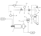
- FIG. 1 schematically shows a part of a modified lignite production apparatus (an example of a solid fuel production apparatus) according to this embodiment.
- this modified lignite production apparatus executes a mixing step in a mixing tank, performs an evaporation step in an evaporator, and executes a solid-liquid separation step in a decanter centrifuge. Moreover, a drying process is performed with the dryer 1 and a modified lignite is obtained.
- the carrier gas is supplied and dried while heating and transporting the modified porous coal.
- nitrogen (N 2 ) as a carrier gas prevents ignition of the modified porous coal.
- the modified porous coal supplied into the dryer 1 is assumed to contain 30 to 40% oil.
- the dryer 1 is provided with a heater (not shown), and an indirect heating type in which the temperature of the internal carrier gas is adjusted to about 200 ° C. is used.
- the modified porous charcoal is transported in the dryer 1 by a screw conveyor.
- the rotating shaft of the screw conveyor is cylindrical, and a plurality of small diameter holes are formed on the outer peripheral surface.
- the carrier gas can be newly supplied into the dryer 1 via the rotating shaft.
- a circulation path 2 for collecting the carrier gas and supplying it again into the dryer 1 is connected to the dryer 1.
- a dust collector 3, a spray tower 4, a blower 5, a flow rate detection sensor 6, a first flow rate adjustment valve 7, and a first pressure detection sensor 8 are provided in order from the outlet side of the dryer 1.
- An exhaust pipe 9 is connected to the pipe from the spray tower 4 to the blower 5, and a second flow rate adjusting valve 10 is provided there. Further, the pressure in the middle of the pipe connecting the dust collector 3 and the spray tower 4 is detected by the second pressure detection sensor 11.
- the detection signal from the flow detection sensor 6 is input to an FIC (Flow Indication Controller) 12.
- a detection signal from the first pressure detection sensor 8 is input to a first PIC (Pressure (Indication Controller) 13.
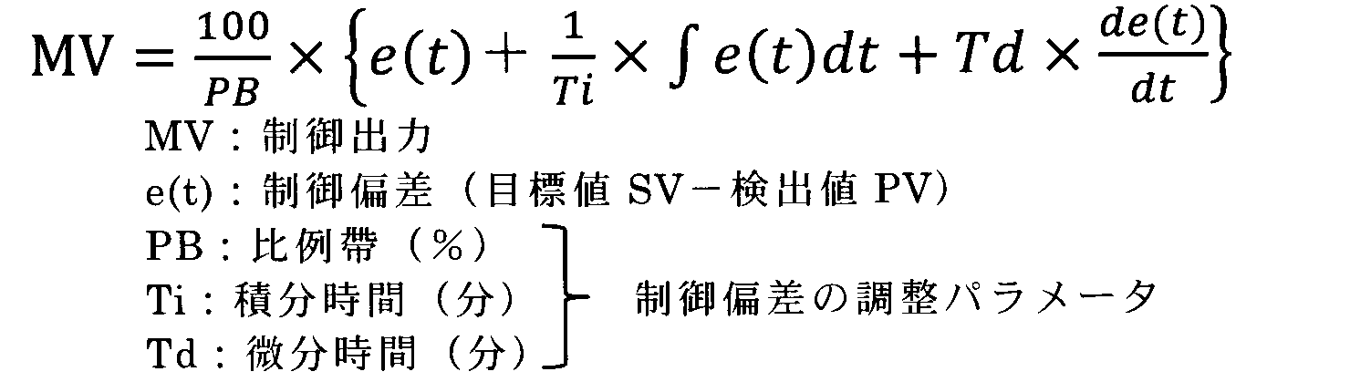
- the FIC 12 and the PIC 13 calculate a control output value according to (Equation 1).
- the control output values calculated by the FIC 12 and the PIC 13 are compared by the LS circuit 14 (Low Select circuit), and the opening degree of the first flow rate adjusting valve 7 is adjusted based on the lower value.
- the pressure of the carrier gas in the circulation path 2 can be within a predetermined range (for example, 1 to 2 kPa. However, this value depends on the seal design and operating conditions of the conveyor, the dryer 1, etc.
- the opening degree of the first flow rate adjusting valve 7 is adjusted so as to be maintained.
- a detection signal from the second pressure detection sensor 11 is input to the second PIC 15. Based on this input signal, the second PIC 15 adjusts the opening of the second flow rate adjusting valve 10 as described later, thereby suppressing an increase in pressure in the circulation path 2.
- the dust collector 3 is for recovering the dust of the modified porous coal contained in the carrier gas discharged from the dryer 1. From the dryer 1 or the dust collector 3, modified brown coal (UBC: Upgraded Brown Coal) is discharged.
- the spray tower 4 is for condensing and separating the mixed oil from the carrier gas that has passed through the dust collector 3.
- the blower 5 is for forming a carrier gas flow from the circulation path 2 to the dryer 1.
- a modified lignite (an example of a solid fuel) is obtained by a mixing step, an evaporation step, a solid-liquid separation step, and a drying step.
- the mixing step the porous charcoal is mixed with the mixed oil containing the solvent oil and the heavy component in a mixing tank to obtain a raw material slurry.
- the evaporation step the raw material slurry obtained in the mixing step is heated with an evaporator to advance dehydration of the porous coal.
- the mixed oil is impregnated into the pores of the porous coal to obtain a dehydrated slurry.
- the modified porous charcoal and the mixed oil are separated from the dehydrated slurry by a decanter centrifuge.
- the drying step the dryer 1 is supplied with a carrier gas while drying and transporting the modified porous coal obtained in the solid-liquid separation step in the dryer 1 to obtain modified lignite.
- the target of the circulation amount of the carrier gas is determined based on the supply amount of the porous coal supplied into the dryer 1 and the amount of oil contained in the porous coal on the outlet side of the decanter centrifuge.
- a value and a target value of the pressure of the carrier gas at the inlet of the dryer 1 are set.
- the carrier is set so that the pressure of the carrier gas in the dryer 1 is within a preset pressure range (set pressure range) with respect to the supply amount of the porous coal and the amount of oil contained therein.
- a target value for the amount of gas circulation and a target value for pressure are set. These target values may be set in advance through experiments or the like.
- Equation 1 (hereinafter referred to as the following equation).
- the value of this control output is referred to as a first control output value).
- the value of the control output is similarly calculated according to (Equation 1). (Hereinafter, this control output value is referred to as a second control output value).
- the calculated control output value is compared by Low Select control, and the opening degree of the 1st flow regulating valve 7 is adjusted according to the smaller value.
- the control output value is calculated based on the flow rate detected by the flow rate detection sensor 6 and the target value, and the first flow rate adjustment valve 7 The opening is adjusted.
- the flow rate of the carrier gas detected by the flow rate detection sensor 6 when the amount of the oil that evaporates inside increases due to the rapid increase in the amount of the modified porous coal carried into the dryer 1. Does not vary so much, but the pressure detected by the first pressure detection sensor 8 increases.
- the second control output value calculated in (Equation 1) is smaller than the first control output value. Therefore, the opening degree of the first flow rate adjusting valve 7 is adjusted based on the second control output value. Thereby, the pressure in the dryer 1 can be maintained within a desired range and stabilized by suppressing the flow rate of the carrier gas to be refluxed into the dryer 1.
- the control output value is calculated according to the above (Equation 1).
- the opening degree of the 2nd flow regulating valve 10 is adjusted based on the calculated control output value.
- the discharged carrier gas is guided to an unillustrated off-gas processing apparatus.
- the carrier gas introduced to the off-gas treatment apparatus is reused by being supplied to the dryer 1 as appropriate.
- the control output value is calculated according to the above (Equation 1). And the opening degree of the 2nd flow regulating valve 10 is adjusted based on the calculated control output value. In this case, since the detected pressure is greatly reduced, the second flow rate adjustment valve 10 is fully closed, and the carrier gas is not discharged to the outside.
- the opening degree of the first flow rate adjusting valve 7 is adjusted accordingly.
- the smaller value of the first control output value and the second control output value is used by the Low / Select control. Therefore, the opening degree of the first flow rate adjusting valve 7 does not change abruptly, and the pressure of the carrier gas in the dryer 1 can be stabilized.
- the opening degree of the first flow rate adjusting valve 7 is adjusted by PID control (Proportional Integral Derivative Controller), but may be performed by other feedback control.
- PID control Proportional Integral Derivative Controller
- the detection signal from the flow rate detection sensor 6 is processed by the FIC 12
- the detection signal from the first pressure detection sensor 8 is processed by the first PIC 13
- the detection signal from the second pressure detection sensor 11 is changed to the first signal.
- the processing is performed by the 2PIC15, these may be collectively controlled by one control unit (microcomputer), or the FIC12 and the first PIC13 may be controlled by one control unit (microcomputer). Good.
Abstract
Description
多孔質炭を溶媒油分及び重質分を含む混合油と混合して原料スラリーを得る混合工程と、
前記原料スラリーを加熱して多孔質炭の脱水を進めると共に、多孔質炭の細孔内に混合油を含浸させて脱水スラリーを得る蒸発工程と、
前記脱水スラリーから改質多孔質炭と混合油とを分離する固液分離工程と、
前記改質多孔質炭を加熱・搬送しながらキャリアガスを供給して乾燥させる乾燥工程と、
を備え、
前記乾燥工程に於けるキャリアガスの循環量の目標値と、キャリアガスの圧力の目標値とを設定し、各目標値と対応する実測値との偏差に基づいて制御出力を演算し、得られた制御出力のうち、小さい方の値に基づいて、キャリアガスの供給量を調整する固形燃料の製造方法を提供する。 As a means for solving the above problems, the present invention provides:
A mixing step of mixing a porous charcoal with a mixed oil containing a solvent oil and a heavy component to obtain a raw slurry;
Evaporating step of heating the raw slurry to advance dehydration of the porous coal, and impregnating the mixed oil into the pores of the porous coal to obtain a dehydrated slurry;
A solid-liquid separation step of separating the modified porous charcoal and the mixed oil from the dewatered slurry;
A drying step of drying by supplying a carrier gas while heating and conveying the modified porous charcoal;
With
The target value of the circulating amount of the carrier gas in the drying step and the target value of the carrier gas pressure are set, and the control output is calculated based on the deviation between each target value and the corresponding measured value. A solid fuel manufacturing method is provided that adjusts the amount of carrier gas supplied based on the smaller value of the control outputs.
多孔質炭を、溶媒油分及び重質分を含む混合油と混合して原料スラリーを得る混合槽と、
前記原料スラリーを加熱して多孔質炭の脱水を進めると共に、多孔質炭の細孔内に混合油を含浸させて脱水スラリーを得る蒸発器と、
前記脱水スラリーから改質多孔質炭と混合油とを分離する遠心分離機と、
前記改質多孔質炭を加熱・搬送しながらキャリアガスを供給して乾燥させる乾燥機と、
前記乾燥機に於ける、キャリアガスの循環量の目標値と、キャリアガスの圧力の目標値とを設定し、各目標値と対応する実測値との偏差に基づいて制御出力を演算し、得られた制御出力のうち、小さい方の値に基づいて、キャリアガスの供給量を調整する制御部と、
を備えた固形燃料の製造装置を提供する。 As a means for solving the above problems, the present invention provides:
A mixing tank for obtaining a raw material slurry by mixing porous charcoal with a mixed oil containing a solvent oil and a heavy oil;
An evaporator that heats the raw slurry to advance dehydration of the porous coal and impregnates the mixed oil into the pores of the porous coal to obtain a dehydrated slurry;
A centrifuge for separating the modified porous charcoal and the mixed oil from the dewatered slurry;
A dryer for drying by supplying a carrier gas while heating and conveying the modified porous charcoal;
In the dryer, a target value for the circulation amount of the carrier gas and a target value for the pressure of the carrier gas are set, and a control output is calculated based on the deviation between each target value and the corresponding measured value. A control unit that adjusts the supply amount of the carrier gas based on the smaller value of the control outputs,
An apparatus for producing a solid fuel comprising:
乾燥機1又は集塵機3からは、改質褐炭(UBC:Upgraded Brown Coal)が排出される。
スプレー塔4は、集塵機3を通過したキャリアガスから混合油を凝縮して分離するためのものである。
ブロワ5は、循環経路2から乾燥機1へのキャリアガスの流れを形成するためのものである。 The
From the
The
The
混合工程では、混合槽で、多孔質炭を、溶媒油分及び重質分を含む混合油と混合して原料スラリーを得る。
蒸発工程では、蒸発器で、混合工程で得られた原料スラリーを加熱し、多孔質炭の脱水を進める。また同時に、多孔質炭の細孔内に混合油を含浸させて脱水スラリーを得る。
固液分離工程では、デカンタ式遠心分離機で、脱水スラリーから改質多孔質炭と混合油とを分離する。
乾燥工程では、乾燥機1で、固液分離工程で得られた改質多孔質炭を加熱・搬送しながらキャリアガスを供給して乾燥させ、改質褐炭を得る。 A modified lignite (an example of a solid fuel) is obtained by a mixing step, an evaporation step, a solid-liquid separation step, and a drying step.
In the mixing step, the porous charcoal is mixed with the mixed oil containing the solvent oil and the heavy component in a mixing tank to obtain a raw material slurry.
In the evaporation step, the raw material slurry obtained in the mixing step is heated with an evaporator to advance dehydration of the porous coal. At the same time, the mixed oil is impregnated into the pores of the porous coal to obtain a dehydrated slurry.
In the solid-liquid separation step, the modified porous charcoal and the mixed oil are separated from the dehydrated slurry by a decanter centrifuge.
In the drying step, the
乾燥工程では、乾燥機1内に供給される多孔質炭の供給量と、デカンタ式遠心分離機の出口側での多孔質炭に含まれる油分量とに基づいて、キャリアガスの循環量の目標値と、乾燥機1の入口に於けるキャリアガスの圧力の目標値とをそれぞれ設定する。この場合、多孔質炭の供給量と、そこに含まれる油分量とに対して、乾燥機1内のキャリアガスの圧力が予め設定した圧力の範囲(設定圧力範囲)内となるように、キャリアガスの循環量の目標値と、圧力の目標値とを設定する。これら目標値の設定は、予め実験等により求めておけばよい。 Hereinafter, the drying process which is a characteristic part of the present invention will be described in detail.
In the drying step, the target of the circulation amount of the carrier gas is determined based on the supply amount of the porous coal supplied into the
循環経路2を流動するキャリアガスの流量及び圧力が安定している場合、流量検出センサ6で検出される流量と、目標値とに基づいて制御出力値が算出され、第1流量調整弁7の開度が調整されている。 Then, the calculated control output value is compared by Low Select control, and the opening degree of the 1st
When the flow rate and pressure of the carrier gas flowing through the
2…循環経路
3…集塵機
4…スプレー塔
5…ブロワ
6…流量検出センサ
7…第1流量調整弁
8…第1圧力検出センサ
9…排気管
10…第2流量調整弁
11…第2圧力検出センサ
12…FIC
13…第1PIC
14…LS回路
15…第2PIC DESCRIPTION OF
13 ... 1st PIC
14 ... LS circuit 15 ... 2nd PIC
Claims (6)
- 多孔質炭を溶媒油分及び重質分を含む混合油と混合して原料スラリーを得る混合工程と、
前記原料スラリーを加熱して多孔質炭の脱水を進めると共に、多孔質炭の細孔内に混合油を含浸させて脱水スラリーを得る蒸発工程と、
前記脱水スラリーから改質多孔質炭と混合油とを分離する固液分離工程と、
前記改質多孔質炭を加熱・搬送しながらキャリアガスを供給して乾燥させる乾燥工程と、
を備え、
前記乾燥工程に於けるキャリアガスの循環量の目標値と、キャリアガスの圧力の目標値とを設定し、各目標値と対応する実測値との偏差に基づいて制御出力を演算し、得られた制御出力のうち、小さい方の値に基づいて、キャリアガスの供給量を調整することを特徴とする固形燃料の製造方法。 A mixing step of mixing a porous charcoal with a mixed oil containing a solvent oil and a heavy component to obtain a raw slurry;
Evaporating step of heating the raw slurry to advance dehydration of the porous coal, and impregnating the mixed oil into the pores of the porous coal to obtain a dehydrated slurry;
A solid-liquid separation step of separating the modified porous charcoal and the mixed oil from the dewatered slurry;
A drying step of drying by supplying a carrier gas while heating and conveying the modified porous charcoal;
With
The target value of the circulating amount of the carrier gas in the drying step and the target value of the carrier gas pressure are set, and the control output is calculated based on the deviation between each target value and the corresponding measured value. A method for producing a solid fuel, wherein the supply amount of the carrier gas is adjusted based on the smaller value of the control outputs. - 前記各目標値は、前記乾燥工程で乾燥させる改質多孔質炭の供給量と、前記乾燥工程を経た改質多孔質炭に含まれる油分量とに基づいて決定することを特徴とする請求項1に記載の固形燃料の製造方法。 Each of the target values is determined based on a supply amount of the modified porous coal to be dried in the drying step and an amount of oil contained in the modified porous coal after the drying step. 2. A method for producing a solid fuel according to 1.
- 前記各目標値は、乾燥工程でのキャリアガスの圧力が予め設定した範囲内となるように決定することを特徴とする請求項2に記載の固形燃料の製造方法。 3. The method for producing a solid fuel according to claim 2, wherein each of the target values is determined so that the pressure of the carrier gas in the drying step is within a preset range.
- 多孔質炭を、溶媒油分及び重質分を含む混合油と混合して原料スラリーを得る混合槽と、
前記原料スラリーを加熱して多孔質炭の脱水を進めると共に、多孔質炭の細孔内に混合油を含浸させて脱水スラリーを得る蒸発器と、
前記脱水スラリーから改質多孔質炭と混合油とを分離する遠心分離機と、
前記改質多孔質炭を加熱・搬送しながらキャリアガスを供給して乾燥させる乾燥機と、
前記乾燥機に於ける、キャリアガスの循環量の目標値と、キャリアガスの圧力の目標値とを設定し、各目標値と対応する実測値との偏差に基づいて制御出力を演算し、得られた制御出力のうち、小さい方の値に基づいて、キャリアガスの供給量を調整する制御部と、
を備えたことを特徴とする固形燃料の製造装置。 A mixing tank for obtaining a raw material slurry by mixing porous charcoal with a mixed oil containing a solvent oil and a heavy oil;
An evaporator that heats the raw slurry to advance dehydration of the porous coal and impregnates the mixed oil into the pores of the porous coal to obtain a dehydrated slurry;
A centrifuge for separating the modified porous charcoal and the mixed oil from the dewatered slurry;
A dryer for drying by supplying a carrier gas while heating and conveying the modified porous charcoal;
In the dryer, a target value for the circulation amount of the carrier gas and a target value for the pressure of the carrier gas are set, and a control output is calculated based on the deviation between each target value and the corresponding measured value. A control unit that adjusts the supply amount of the carrier gas based on the smaller value of the control outputs,
An apparatus for producing solid fuel, comprising: - 前記制御部は、前記各目標値を、前記乾燥機で乾燥させる改質多孔質炭の供給量と、前記乾燥機を経た改質多孔質炭に含まれる油分量とに基づいて決定することを特徴とする請求項4に記載の固形燃料の製造装置。 The control unit determines the target values based on the supply amount of the modified porous coal to be dried by the dryer and the amount of oil contained in the modified porous coal that has passed through the dryer. The solid fuel manufacturing apparatus according to claim 4, wherein the apparatus is a solid fuel manufacturing apparatus.
- 前記制御部は、前記各目標値を、乾燥工程でのキャリアガスの圧力が予め設定した範囲内となるように決定することを特徴とする請求項5に記載の固形燃料の製造装置。 6. The solid fuel production apparatus according to claim 5, wherein the control unit determines the target values so that the pressure of the carrier gas in the drying step is within a preset range.
Priority Applications (5)
| Application Number | Priority Date | Filing Date | Title |
|---|---|---|---|
| AU2014282553A AU2014282553B2 (en) | 2013-06-19 | 2014-04-02 | Solid fuel manufacturing method and manufacturing device |
| RU2015154278A RU2629935C2 (en) | 2013-06-19 | 2014-04-02 | Solid fuel manufacturing method and manufacturing plant |
| EP14813034.7A EP3012313A4 (en) | 2013-06-19 | 2014-04-02 | Solid fuel manufacturing method and manufacturing device |
| CN201480034105.7A CN105308160B (en) | 2013-06-19 | 2014-04-02 | The manufacture method and manufacture device of solid fuel |
| US14/892,151 US20160122675A1 (en) | 2013-06-19 | 2014-04-02 | Solid fuel manufacturing method and manufacturing device |
Applications Claiming Priority (2)
| Application Number | Priority Date | Filing Date | Title |
|---|---|---|---|
| JP2013-128778 | 2013-06-19 | ||
| JP2013128778A JP6023665B2 (en) | 2013-06-19 | 2013-06-19 | Method and apparatus for producing solid fuel |
Publications (1)
| Publication Number | Publication Date |
|---|---|
| WO2014203591A1 true WO2014203591A1 (en) | 2014-12-24 |
Family
ID=52104335
Family Applications (1)
| Application Number | Title | Priority Date | Filing Date |
|---|---|---|---|
| PCT/JP2014/059767 WO2014203591A1 (en) | 2013-06-19 | 2014-04-02 | Solid fuel manufacturing method and manufacturing device |
Country Status (7)
| Country | Link |
|---|---|
| US (1) | US20160122675A1 (en) |
| EP (1) | EP3012313A4 (en) |
| JP (1) | JP6023665B2 (en) |
| CN (1) | CN105308160B (en) |
| AU (1) | AU2014282553B2 (en) |
| RU (1) | RU2629935C2 (en) |
| WO (1) | WO2014203591A1 (en) |
Families Citing this family (3)
| Publication number | Priority date | Publication date | Assignee | Title |
|---|---|---|---|---|
| CN110849104A (en) * | 2019-11-20 | 2020-02-28 | 攀枝花钢城集团瑞通制冷设备有限公司 | Mineral powder drying device |
| CN111550979B (en) * | 2020-05-12 | 2021-09-21 | 南京六合高新建设发展有限公司 | Vulcanization compression drying device |
| CN111534353B (en) * | 2020-05-14 | 2021-09-03 | 太原理工大学 | Coking process and device |
Citations (4)
| Publication number | Priority date | Publication date | Assignee | Title |
|---|---|---|---|---|
| JPH07233383A (en) | 1993-12-27 | 1995-09-05 | Kobe Steel Ltd | Solid fuel using porous coal as raw material, its production and apparatus for production |
| JP2008144114A (en) * | 2006-12-13 | 2008-06-26 | Kobe Steel Ltd | Manufacturing method and manufacturing apparatus of solid fuel |
| JP2009097783A (en) * | 2007-10-16 | 2009-05-07 | Kobe Steel Ltd | Indirect heating/drying device, indirect heating/drying method for object to be dried, method for manufacturing solid fuel, and its manufacturing device |
| JP2011214808A (en) * | 2010-04-02 | 2011-10-27 | Mitsubishi Heavy Ind Ltd | Drying device, drying facility and drying method |
Family Cites Families (13)
| Publication number | Priority date | Publication date | Assignee | Title |
|---|---|---|---|---|
| DE2510737A1 (en) * | 1975-03-12 | 1976-09-30 | Buettner Schilde Haas Ag | PLANT FOR HEATING AND DRYING COAL IN A CIRCUIT UNDER PRESSURE |
| DE4446401C2 (en) * | 1993-12-27 | 1998-07-02 | Kobe Steel Ltd | Solid fuel made from porous coal and method and apparatus for producing the same |
| DE29621313U1 (en) * | 1996-12-07 | 1997-01-30 | Digicolor Gmbh | Device for drying granules |
| SE512787C2 (en) * | 1997-10-03 | 2000-05-15 | Abb Ab | Method, control paradigm and device for controlling and monitoring the process variables for a process gas flowing through a chamber used for drying |
| JP3783582B2 (en) * | 2001-07-05 | 2006-06-07 | ダイキン工業株式会社 | Hydraulic circuit device |
| US7187856B2 (en) * | 2001-08-27 | 2007-03-06 | Flexair, Inc. | Compact integrated forced air drying system |
| DE202004012482U1 (en) * | 2004-08-07 | 2004-11-04 | Wittmann Robot Systeme Gmbh | Device for the optimized heating and drying of bulk goods, especially plastic powder or plastic granules |
| SE529334C2 (en) * | 2005-11-23 | 2007-07-10 | Svensk Roekgasenergi Intressen | Drying apparatus for particulate matter |
| DE102007005782B3 (en) * | 2007-02-06 | 2008-02-14 | Uhde Gmbh | Procedure for drying dust residue in gasification of fuels e.g. coal, comprises crushing the fuel in grinder, supplying the fuel to filter/separator by conveying- and drying gas, and redirecting the conveying/drying gas into the grinder |
| US8574329B2 (en) * | 2008-12-11 | 2013-11-05 | General Electric Company | Method of operating a gasifier |
| JP2011214810A (en) * | 2010-04-02 | 2011-10-27 | Mitsubishi Heavy Ind Ltd | Low-grade coal drying system |
| JP5431382B2 (en) * | 2011-02-07 | 2014-03-05 | 三菱重工環境・化学エンジニアリング株式会社 | Evaporative load control system for dryer |
| JP5809012B2 (en) * | 2011-10-14 | 2015-11-10 | 株式会社堀場エステック | Diagnosis device and diagnostic program used in a flow control device, a flow measurement mechanism, or a flow control device including the flow measurement mechanism |
-
2013
- 2013-06-19 JP JP2013128778A patent/JP6023665B2/en active Active
-
2014
- 2014-04-02 EP EP14813034.7A patent/EP3012313A4/en not_active Withdrawn
- 2014-04-02 RU RU2015154278A patent/RU2629935C2/en active
- 2014-04-02 AU AU2014282553A patent/AU2014282553B2/en active Active
- 2014-04-02 US US14/892,151 patent/US20160122675A1/en not_active Abandoned
- 2014-04-02 WO PCT/JP2014/059767 patent/WO2014203591A1/en active Application Filing
- 2014-04-02 CN CN201480034105.7A patent/CN105308160B/en active Active
Patent Citations (4)
| Publication number | Priority date | Publication date | Assignee | Title |
|---|---|---|---|---|
| JPH07233383A (en) | 1993-12-27 | 1995-09-05 | Kobe Steel Ltd | Solid fuel using porous coal as raw material, its production and apparatus for production |
| JP2008144114A (en) * | 2006-12-13 | 2008-06-26 | Kobe Steel Ltd | Manufacturing method and manufacturing apparatus of solid fuel |
| JP2009097783A (en) * | 2007-10-16 | 2009-05-07 | Kobe Steel Ltd | Indirect heating/drying device, indirect heating/drying method for object to be dried, method for manufacturing solid fuel, and its manufacturing device |
| JP2011214808A (en) * | 2010-04-02 | 2011-10-27 | Mitsubishi Heavy Ind Ltd | Drying device, drying facility and drying method |
Non-Patent Citations (1)
| Title |
|---|
| See also references of EP3012313A4 * |
Also Published As
| Publication number | Publication date |
|---|---|
| CN105308160A (en) | 2016-02-03 |
| AU2014282553A1 (en) | 2016-01-07 |
| JP6023665B2 (en) | 2016-11-09 |
| AU2014282553B2 (en) | 2016-07-14 |
| EP3012313A4 (en) | 2017-03-01 |
| JP2015003956A (en) | 2015-01-08 |
| US20160122675A1 (en) | 2016-05-05 |
| RU2015154278A (en) | 2017-07-24 |
| CN105308160B (en) | 2017-11-14 |
| EP3012313A1 (en) | 2016-04-27 |
| RU2629935C2 (en) | 2017-09-05 |
Similar Documents
| Publication | Publication Date | Title |
|---|---|---|
| JP6023665B2 (en) | Method and apparatus for producing solid fuel | |
| CN102455114B (en) | The dewatering of granular material and equipment | |
| JP2007017107A (en) | Drying system | |
| US10634429B2 (en) | Continuous-flow dryer comprising an exhaust air recirculation device | |
| US10914519B2 (en) | Method for producing salts with a reduced water of crystallisation content | |
| JP2023126837A (en) | Drying facility, and method of maintaining negative pressure | |
| JP6846920B2 (en) | Organic waste treatment method and treatment equipment | |
| JP2006263662A (en) | Sludge carbonizing system | |
| JP4848894B2 (en) | Sludge supply equipment for carbonization furnace | |
| KR102407456B1 (en) | Indirect heat-drying device and method for drying low-grade coal | |
| CN204478750U (en) | A kind of rotary kiln drying machine | |
| US10426183B2 (en) | Apparatus and a method for recovery of meal | |
| JP6775286B2 (en) | Drying device and drying system equipped with it | |
| JP6173953B2 (en) | Pyrolysis system and carbonized sludge manufacturing method | |
| JP5618789B2 (en) | Vacuum dryer and operation control method | |
| JP2017217622A (en) | Production method of magnetic carbonized product and sludge carbonization apparatus | |
| US20180306506A1 (en) | Continuous-flow dryer comprising a first and a second section | |
| CN103836904A (en) | Feeding system used for vacuum belt type powder continuous drying machine | |
| CN210500943U (en) | Miniature split type camera lens desiccator | |
| JPH0688084A (en) | Operation of rotating heating drier equipped with steam pipe | |
| JP6399400B2 (en) | Drying method of the object to be dried | |
| BR112021001268A2 (en) | method for treating lignin. | |
| JPH0734919B2 (en) | Drying equipment for water-containing waste | |
| JPH10158659A (en) | Method for operating humidity conditioner for coal fed into coke oven | |
| JPH04272993A (en) | Method for operating heat-transfer tube dryer for moisture control of coal |
Legal Events
| Date | Code | Title | Description |
|---|---|---|---|
| WWE | Wipo information: entry into national phase |
Ref document number: 201480034105.7 Country of ref document: CN |
|
| 121 | Ep: the epo has been informed by wipo that ep was designated in this application |
Ref document number: 14813034 Country of ref document: EP Kind code of ref document: A1 |
|
| WWE | Wipo information: entry into national phase |
Ref document number: 14892151 Country of ref document: US |
|
| WWE | Wipo information: entry into national phase |
Ref document number: 2014813034 Country of ref document: EP |
|
| WWE | Wipo information: entry into national phase |
Ref document number: IDP00201508585 Country of ref document: ID |
|
| NENP | Non-entry into the national phase |
Ref country code: DE |
|
| ENP | Entry into the national phase |
Ref document number: 2014282553 Country of ref document: AU Date of ref document: 20140402 Kind code of ref document: A |
|
| ENP | Entry into the national phase |
Ref document number: 2015154278 Country of ref document: RU Kind code of ref document: A |