WO2014203410A1 - Electrolyte for redox flow battery and redox flow battery - Google Patents
Electrolyte for redox flow battery and redox flow battery Download PDFInfo
- Publication number
- WO2014203410A1 WO2014203410A1 PCT/JP2013/071427 JP2013071427W WO2014203410A1 WO 2014203410 A1 WO2014203410 A1 WO 2014203410A1 JP 2013071427 W JP2013071427 W JP 2013071427W WO 2014203410 A1 WO2014203410 A1 WO 2014203410A1
- Authority
- WO
- WIPO (PCT)
- Prior art keywords
- less
- concentration
- element ions
- mass ppm
- redox flow
- Prior art date
Links
Images

Classifications
-
- H—ELECTRICITY
- H01—ELECTRIC ELEMENTS
- H01M—PROCESSES OR MEANS, e.g. BATTERIES, FOR THE DIRECT CONVERSION OF CHEMICAL ENERGY INTO ELECTRICAL ENERGY
- H01M8/00—Fuel cells; Manufacture thereof
- H01M8/20—Indirect fuel cells, e.g. fuel cells with redox couple being irreversible
-
- H—ELECTRICITY
- H01—ELECTRIC ELEMENTS
- H01M—PROCESSES OR MEANS, e.g. BATTERIES, FOR THE DIRECT CONVERSION OF CHEMICAL ENERGY INTO ELECTRICAL ENERGY
- H01M8/00—Fuel cells; Manufacture thereof
- H01M8/18—Regenerative fuel cells, e.g. redox flow batteries or secondary fuel cells
-
- H—ELECTRICITY
- H01—ELECTRIC ELEMENTS
- H01M—PROCESSES OR MEANS, e.g. BATTERIES, FOR THE DIRECT CONVERSION OF CHEMICAL ENERGY INTO ELECTRICAL ENERGY
- H01M8/00—Fuel cells; Manufacture thereof
- H01M8/18—Regenerative fuel cells, e.g. redox flow batteries or secondary fuel cells
- H01M8/184—Regeneration by electrochemical means
- H01M8/188—Regeneration by electrochemical means by recharging of redox couples containing fluids; Redox flow type batteries
-
- H—ELECTRICITY
- H01—ELECTRIC ELEMENTS
- H01M—PROCESSES OR MEANS, e.g. BATTERIES, FOR THE DIRECT CONVERSION OF CHEMICAL ENERGY INTO ELECTRICAL ENERGY
- H01M2300/00—Electrolytes
- H01M2300/0017—Non-aqueous electrolytes
- H01M2300/002—Inorganic electrolyte
-
- Y—GENERAL TAGGING OF NEW TECHNOLOGICAL DEVELOPMENTS; GENERAL TAGGING OF CROSS-SECTIONAL TECHNOLOGIES SPANNING OVER SEVERAL SECTIONS OF THE IPC; TECHNICAL SUBJECTS COVERED BY FORMER USPC CROSS-REFERENCE ART COLLECTIONS [XRACs] AND DIGESTS
- Y02—TECHNOLOGIES OR APPLICATIONS FOR MITIGATION OR ADAPTATION AGAINST CLIMATE CHANGE
- Y02E—REDUCTION OF GREENHOUSE GAS [GHG] EMISSIONS, RELATED TO ENERGY GENERATION, TRANSMISSION OR DISTRIBUTION
- Y02E60/00—Enabling technologies; Technologies with a potential or indirect contribution to GHG emissions mitigation
- Y02E60/30—Hydrogen technology
- Y02E60/50—Fuel cells
Definitions
- the present invention relates to an electrolyte for a redox flow battery, and a redox flow battery using the electrolyte for a redox flow battery.
- a redox flow battery is a secondary battery that performs charging and discharging by supplying a positive electrode electrolyte and a negative electrode electrolyte to a battery cell in which a diaphragm is interposed between a positive electrode and a negative electrode.
- An electrolyte solution for a redox flow battery used in such a redox flow battery normally uses a metal element whose valence is changed by oxidation and reduction as an active material.
- a vanadium (V 2+ / V 3+ -V 4+ / V 5+ ) -based redox flow battery using vanadium (V) ions as an active material can be given.
- the battery has a higher energy density.
- the solubility of the active material in the electrolytic solution for example, it is conceivable to increase the solubility of the active material in the electrolytic solution or increase the utilization factor of the electrolytic solution, that is, the utilization factor of the active material.
- This utilization rate means the ratio (discharge capacity / theoretical battery capacity) of the battery capacity (discharge capacity) that can actually be used to the theoretical battery capacity (Ah) of the active material.
- the discharge capacity is the difference between the battery capacity in the lower limit state of charge (SOC: State of Charge) and the battery capacity in the upper limit state of charge.
- the side reaction is (1) current loss (a part of the amount of electricity (Ah) used at the time of charging is not used for battery reaction (change in valence), but used for another reaction such as decomposition of water). Loss), (2) causes the charge state of the positive and negative electrodes to be different, reduces the usable battery capacity, (3) shortens the battery life due to electrode deterioration, etc. Bring about evil. Therefore, in actual battery operation, since the charge stop voltage (upper limit charge voltage) is determined so as to be used in a range in which the side reaction does not occur, it is difficult to make the state of charge 90% or more.
- Patent Document 1 discloses a redox flow battery in which at least a negative electrode electrolyte contains metal ions having a lower potential than vanadium ions in a vanadium-based redox flow battery.
- metal ions at the base potential are reduced before the side reaction occurs, thereby suppressing generation of hydrogen in the negative electrode.
- the adverse effects (1) to (3) above can be suppressed, and the battery capacity in the upper limit charging state can be increased to nearly 100% of that in theory, so that the redox flow battery with high energy density can be obtained.
- Patent Document 1 exemplifies chromium (Cr) ions and zinc (Zn) ions as metal ions having a lower potential than vanadium ions.
- Patent Document 1 may generate hydrogen. That is, there is a possibility that the factors that generate hydrogen are not fully specified.
- one of the objects of the present invention is to provide a redox flow battery electrolyte that can suppress the generation of hydrogen. Moreover, the other object of this invention is to provide a redox flow battery provided with this electrolyte solution for redox flow batteries.
- the total concentration of platinum group element ions is 4.5 mass ppm or less.
- the redox flow battery electrolyte solution (hereinafter referred to as RF electrolyte solution) according to the embodiment has a total concentration of platinum group element ions of 4.5 mass ppm or less.
- the inventors of the present invention have found that the type and concentration of impurity element ions in the RF electrolyte greatly affect the generation of hydrogen during the battery reaction of a redox flow battery (hereinafter referred to as an RF battery).
- an RF battery a redox flow battery
- the generation of hydrogen is promoted when the total concentration (total amount) of platinum group element ions is a certain level or more, and it has been found that the generation of hydrogen can be suppressed by defining the total amount. Therefore, according to the RF electrolyte solution of the present embodiment, generation of hydrogen can be suppressed, and as a result, the energy density of the RF battery can be increased.
- the element ion is a general term for all valence ions generated from the same element. Further, regarding the concentration, the total concentration of ions of all valences generated from the same element is shown.
- Impurity element ions are element ions contained in the RF electrolyte solution and do not contribute to the battery reaction. Therefore, the active ions are included in the element ions, but the active materials contribute to the battery reaction and thus are not included in the impurity element ions. Since platinum group elements do not contribute to the battery reaction, they are impurity element ions.
- the platinum group element is a general term for ruthenium (Ru), rhodium (Rh), palladium (Pd), osmium (Os), iridium (Ir), and platinum (Pt).
- the concentration of the platinum group element ion satisfies at least one of the following (1) to (4).
- Rhodium (Rh) ion concentration is 1 mass ppm or less
- Palladium (Pd) ion concentration is 1 mass ppm or less
- Iridium (Ir) ion concentration is 1 mass ppm or less
- Platinum ( Pt) ion concentration is 1 mass ppm or less
- the above platinum group element ions are particularly easy to promote the generation of hydrogen among the platinum group element ions. Therefore, the RF electrolyte solution in which the concentration of each platinum group element ion is adjusted can suppress hydrogen generated during the battery reaction, particularly at the end of charging, and by increasing the utilization rate of the active material, thereby increasing the energy density of the RF battery. Can be increased.
- the concentration of V ions is 1 mol / L to 3 mol / L
- the concentration of free sulfuric acid is 1 mol / L to 4 mol. / L or less
- phosphoric acid concentration is 1.0 ⁇ 10 ⁇ 4 mol / L or more and 7.1 ⁇ 10 ⁇ 1 mol / L or less
- ammonium concentration is 20 mass ppm or less
- silicon concentration is 40 mass ppm or less.
- the RF electrolyte solution having the above-described configuration can suppress the generation of hydrogen during the battery reaction, particularly at the end of charging, and can increase the energy density of the RF battery by increasing the utilization factor of the active material. Moreover, as will be described later, the RF electrolyte solution having the above-described configuration can suppress precipitates generated during the battery reaction, and thus can suppress a decrease in battery performance over time.
- the RF battery according to the embodiment includes the RF electrolyte solution according to any one of the embodiments (A) to (C).
- the RF battery according to the present embodiment includes an RF electrolyte solution in which the generation of hydrogen is suppressed, thereby preventing deterioration of battery performance with time and making it an RF battery with a high energy density.
- an RF battery and an RF electrolyte solution according to the embodiment will be described using an RF battery 1 using V ions as a positive electrode active material and a negative electrode active material as an example.
- a solid line arrow indicates a valence change during charging, and a broken line arrow indicates a valence change during discharging.
- the valence of the active material (V ions) shows only a typical form, and valences other than those shown can be taken.
- An active material other than V ions may be included.
- the RF battery 1 typically has an AC / DC converter between a power generation unit (for example, a solar power generation device, a wind power generation device, or other general power plant) and a load (such as a consumer).
- the power generated by the power generation unit is charged and stored, or the stored power is discharged and supplied to the load.
- the RF battery 1 includes a battery cell 100 and a circulation mechanism (tank, piping, pump) for supplying an electrolytic solution to the battery cell 100 as in the case of a conventional RF battery.
- the battery cell 100 in the RF battery 1 includes a positive electrode cell 102 incorporating a positive electrode 104, a negative electrode cell 103 incorporating a negative electrode 105, and a diaphragm 101 that separates both the cells 102 and 103 and transmits ions.
- a positive electrode tank 106 for storing a positive electrode electrolyte is connected to the positive electrode cell 102 via pipes 108 and 110.
- a negative electrode tank 107 that stores a negative electrode electrolyte is connected to the negative electrode cell 103 via pipes 109 and 111.
- the pipes 108 and 109 are provided with pumps 112 and 113 for circulating the electrolytes of both electrodes, respectively.
- the battery cell 100 is connected to the positive electrode cell 106 (positive electrode 104) and the negative electrode cell 103 (negative electrode 105) by pipes 108 to 111 and pumps 112 and 113, respectively, and the negative electrode in the positive electrode tank 106 and the negative electrode in the negative electrode tank 107.
- the electrolytic solution is circulated and supplied, and charging / discharging is performed in accordance with a change in the valence of metal ions (V ions in the present embodiment) that are active materials in the electrolytic solution in both electrodes.
- the battery cell 100 is normally used in a form called a cell stack in which a plurality of single cells each having a positive electrode 104 (positive cell 102), a negative electrode 105 (negative electrode 103), and a diaphragm 101 are stacked.
- the cell stack has a bipolar plate (not shown) in which the positive electrode 104 is disposed on one surface and the negative electrode 105 is disposed on the other surface, a liquid supply hole for supplying an electrolytic solution, and a drain hole for discharging the electrolytic solution.
- a cell frame provided with a frame (not shown) formed on the outer periphery of the bipolar plate is used.
- the liquid supply hole and the drainage hole constitute an electrolyte flow path, and the flow path is connected to the pipes 108 to 111.
- the cell stack is configured by stacking a cell frame, a positive electrode 104, a diaphragm 101, a negative electrode 105, a cell frame,.
- a known configuration can be used as appropriate.
- the RF electrolyte solution of this embodiment is a liquid in which element ions serving as active materials are contained in a solvent, and the concentration of platinum group element ions is very low. Further, as is clear from the test examples described later, the concentration of impurity element ions involved in the generation of precipitates can be set to a predetermined value or less as necessary.
- an RF electrolyte solution containing V ions as an active material is used for the positive electrode electrolyte and the negative electrode electrolyte.
- the average valence of V ions in the positive electrode electrolyte and the negative electrode electrolyte is preferably 3.3 to 3.7 and the concentration is preferably 1 mol / L to 3 mol / L. More preferable average valence is 3.4 or more and 3.6 or less, and V ion concentration is 1.5 mol / L or more and 1.9 mol / L or less.
- the solvent for the RF electrolyte examples include H 2 SO 4 , K 2 SO 4 , Na 2 SO 4 , H 3 PO 4 , H 4 P 2 O 7 , K 2 HPO 4 , Na 3 PO 4 , and K 3 PO. 4 , at least one aqueous solution selected from HNO 3 , KNO 3 , HCl, and NaNO 3 can be used.
- an organic acid solvent can be used as a solvent for the RF electrolyte.
- platinum group element ions As a result of the study by the present inventors, it has been found that generation of hydrogen can be effectively suppressed if the total concentration of platinum group element ions in the RF electrolyte solution is 4.5 mass ppm or less.
- the platinum group element ions that promote the generation of hydrogen include the following, and it has also been found that the concentration of each platinum group element ion preferably satisfies the above-mentioned concentration. (1) Rh ion: 1 mass ppm or less (2) Pd ion: 1 mass ppm or less (3) Ir ion: 1 mass ppm or less (4) Pt ion: 1 mass ppm or less
- filtration using a chelate resin is preferable because specific element ions can be selectively filtered by adjusting the physical properties of the chelate resin and the pH of the RF electrolyte.
- an RF electrolyte solution may be passed through a filter made of a chelate resin, a column filled with a chelate resin in the form of beads, or the like.
- the present inventors have classified platinum group element ions into element ions belonging to group 9 (group 9 element ions), element ions belonging to group 10 (group 10 element ions), and element ions belonging to other groups (hereinafter referred to as group ions). In other words, it has been found that there is a preferable total concentration when the group 9 element ion and the group 10 element ion are satisfied.
- the group 9 element ions and the group 10 element ions include platinum group element ions that promote the generation of hydrogen. Since homologous elements have similar properties, they can often be removed under similar (single) conditions when removing impurity element ions from the RF electrolyte. In addition, when it is difficult to remove one of the group 9 element ions and the group 10 element ions, the total concentration of the group element ions that can be easily removed may be adjusted. Therefore, in this classification, it is not necessary to change the conditions in order to remove individual element ions.
- the platinum group element ions satisfy at least one of the following (a) and (b) in the RF electrolyte solution in which the total concentration of platinum group element ions is 4.5 mass ppm or less.
- the total concentration of group 9 element ions is 2 mass ppm or less.
- the total concentration of group 10 element ions is 2 mass ppm or less.
- the concentration of V ions is 1 mol / L or more and 3 mol / L or less
- the concentration of free sulfuric acid is 1 mol / L or more and 4 mol / L or less
- ammonium (NH 4 ) concentration of 20 mass ppm or less and silicon (Si) concentration of 40 mass ppm or less. It is preferable that
- the average valence of the RF electrolyte solution is about 3.3 or more and 3.7 or less.
- Such an average valence RF electrolyte solution has a good balance of V ion concentration of each valence as both the positive electrode side electrolyte solution and the negative electrode side electrolyte solution. Therefore, when an RF battery is configured using such an average valence RF electrolyte, the capacity of the RF battery can be made very high.
- precipitation for example, ammonium-vanadium compound precipitated during the battery reaction can be prevented. Can be suppressed.
- Si can adversely affect the diaphragm, it is possible to suppress this adverse effect by setting the concentration below the above specific concentration.
- the positive electrode tank 106, the negative electrode tank 107, and the pipes 108 to 111 are members in contact with the RF electrolyte solution. Therefore, there is a possibility that these element (106 to 111) contain or adhere to impurity element ions or platinum group element ions involved in the generation of precipitates during the battery reaction. In this case, the content of the impurity element ions or platinum group element ions in the RF electrolyte may increase with the operation of the RF battery 1. Therefore, it is preferable to use a material that does not contain the impurity element ions or platinum group element ions as the constituent materials of these members (106 to 111).
- those containing no impurity element ions or platinum group element ions for example, the impurity element ions or platinum group elements included in a mold release agent for producing the member
- those not containing ions it is preferable to use those not containing ions.
- the constituent material of the member (106-111), density (ASTM D 1505) is in 0.080 g / cm 3 or more 0.960 g / cm 3 within the range, the melt flow rate (ASTM D 1238, measured Conditions: 190 ° C., load 2.16 kg) of ethylene homopolymer in the range of 0.01 g / 10 min to 20 g / 10 min, or ethylene / ⁇ -olein co-polymer with density and melt flow rate in the above range Examples include coalescence. The same applies to the above-described members (106 to 111) in the transport tank for transporting the RF electrolyte solution.
- Test Example 1 a charge / discharge test was performed assuming an RF battery to be used in actual operation. First, a carbon felt positive electrode and negative electrode having an electrode area of 500 cm 2 were prepared. The total mass of both electrodes was about 35 g. In addition, three types of RF electrolytes having different impurity element ion concentrations were prepared as RF electrolytes, and three types of two-hour capacity RF batteries were prepared using the respective RF electrolytes. The prepared RF electrolyte solution has the following common basic configuration.
- V ion concentration 1.7 mol / L -Average valence of V ion: 3.5 -Free sulfuric acid concentration: 2.0 mol / L ⁇ Phosphoric acid concentration: 0.14 mol / L -Silicon concentration: 40 mass ppm or less-Ammonium concentration: 20 mass ppm or less
- Table 1 shows the concentration of impurity element ions in each RF electrolyte used in this test example.
- the numerical values in Table 1 represent the concentration (mass ppm).
- the concentration of the impurity element ions was adjusted by passing each RF electrolyte through a column filled with a chelate resin as necessary.
- Impurity element ions are measured by measuring an ion chromatography system (manufactured by Nippon Dionex Co., Ltd., ICS-1500) and measuring a Na ion and a K ion by a polarized Zeeman atomic absorption spectrophotometer (Co., Ltd.).
- the charge / discharge conditions are as follows.
- production of hydrogen can be suppressed if the total density
- production of a precipitate can be suppressed as the total density
- production of a precipitate is 220 mass ppm or less.
- the total concentration of metal element ions is preferably 195 mass ppm or less (see, for example, Test Example 2-4).
- the total concentration of nonmetallic element ions is preferably 21 ppm by mass or less (see, for example, Test Example 1-2).
- the total concentration of heavy metal element ions is preferably 85 ppm by mass or less (for example, compare Test Example 1-2 and Test Example 1-3).
- the total concentration of light metal element ions is preferably 120 ppm by mass or less (for example, compare Test Example 1-2 and Test Example 1-3).
- the total concentration of heavy metal element ions is preferably 85 mass ppm or less, and the total concentration of light metal element ions is preferably 120 mass ppm or less (for example, test example 2-2 reference).
- the following is preferable (for example, see Table 1).
- Rh ion: 1 mass ppm or less (2) Pd ion: 1 mass ppm or less, (3) Ir ion: 1 mass ppm or less, (4) Pt ion: 1 mass ppm or less (5) Cr ion: 10 Mass ppm or less, (6) Mn ion: 1 mass ppm or less, (7) Fe ion: 40 mass ppm or less, (8) Co ion: 2 mass ppm or less, (9) Ni ion: 5 mass ppm or less, (10 ) Cu ion: 1 mass ppm or less, (11) Zn ion: 1 mass ppm or less, (12) Mo ion: 20 mass ppm or less, (13) Sb ion: 1 mass ppm or less, (14) Na ion: 30 mass ppm or less, (15) Mg ion: 20 mass ppm or less, (16) Al ion: 15 mass ppm or less, (17) K ion: 20 mass ppm
- the element ions included in the group consisting of the impurity element ions involved in the generation of precipitates and the platinum group element ions are changed into group 9 element ions, group 10 element ions, and element ions of other groups.
- the results for the case of classification are shown in Table 5.
- the total concentration of group 9 element ions is 4 mass ppm or less, and the total of group 10 element ions The concentration may be in a range satisfying at least one of 7 ppm by mass or less and the total concentration of other group element ions of 190 ppm by mass or less.
- the total concentration of impurity element ions involved in the generation of precipitates during the battery reaction is 220 mass ppm or less, and the total concentration of platinum group element ions is 4.5 mass ppm or less
- Element ions included in the group of impurity element ions involved in the generation of precipitates and platinum group element ions are group 9 element ions, group 10 element ions, and group 9 element ions.
- an electrolyte for a redox flow battery satisfying at least one of the following (c) to (e) when classified into element ions other than element ions belonging to Group 10.
- Total concentration of element ions belonging to group 9 is 4 mass ppm or less
- Total concentration of element ions belonging to group 10 is 7 mass ppm or less
- Element ions belonging to group 9 and element ions belonging to group 10 The total concentration of other element ions is 190 mass ppm or less
- the electrolyte solution for redox flow batteries of the present invention can be suitably used as an electrolyte solution for secondary batteries such as redox flow batteries.
- the redox flow battery of the present invention can be suitably used as a battery for load leveling or for measures against instantaneous voltage drop and power failure.
Abstract
Description
最初に本願発明の実施形態の内容を列記して説明する。
(A)実施形態に係るレドックスフロー電池用電解液(以下、RF電解液と呼ぶ)は、白金族元素イオンの合計濃度が4.5質量ppm以下である。 [Description of Embodiment of Present Invention]
First, the contents of the embodiments of the present invention will be listed and described.
(A) The redox flow battery electrolyte solution (hereinafter referred to as RF electrolyte solution) according to the embodiment has a total concentration of platinum group element ions of 4.5 mass ppm or less.
(1)ロジウム(Rh)イオンの濃度が1質量ppm以下
(2)パラジウム(Pd)イオンの濃度が1質量ppm以下
(3)イリジウム(Ir)イオンの濃度が1質量ppm以下
(4)白金(Pt)イオンの濃度が1質量ppm以下 (B) It is preferable that the concentration of the platinum group element ion satisfies at least one of the following (1) to (4).
(1) Rhodium (Rh) ion concentration is 1 mass ppm or less (2) Palladium (Pd) ion concentration is 1 mass ppm or less (3) Iridium (Ir) ion concentration is 1 mass ppm or less (4) Platinum ( Pt) ion concentration is 1 mass ppm or less
本願発明の実施形態に係るRF電解液を、以下に図面を参照しつつ説明する。なお、本発明はこれらの実施形態に限定されるものではなく、特許請求の範囲によって示され、特許請求の範囲と均等の意味及び範囲内でのすべての変更が含まれることが意図される。 [Details of the embodiment of the present invention]
An RF electrolyte solution according to an embodiment of the present invention will be described below with reference to the drawings. In addition, this invention is not limited to these embodiment, It is shown by the claim and it is intended that all the changes within the meaning and range equivalent to a claim are included.
RF電池1は、代表的には、交流/直流変換器を介して、発電部(例えば、太陽光発電装置や風力発電装置、その他一般の発電所など)と負荷(需要家など)との間に接続され、発電部で発電した電力を充電して蓄え、又は、蓄えた電力を放電して負荷に供給する。このRF電池1は、従来のRF電池と同様に、電池セル100と、この電池セル100に電解液を供給する循環機構(タンク、配管、ポンプ)とを備える。 <Overall configuration of RF battery>
The
RF電池1における電池セル100は、正極電極104を内蔵する正極セル102と、負極電極105を内蔵する負極セル103と、両セル102,103を分離すると共にイオンを透過する隔膜101とを備える。正極セル102には、正極電解液を貯留する正極用タンク106が配管108,110を介して接続されている。負極セル103には、負極電解液を貯留する負極用タンク107が配管109,111を介して接続されている。また、配管108,109にはそれぞれ、両極の電解液を循環させるポンプ112,113が設けられている。電池セル100は、配管108~111とポンプ112,113によって、正極セル102(正極電極104)及び負極セル103(負極電極105)にそれぞれ正極用タンク106の正極電解液及び負極用タンク107の負極電解液を循環供給して、両極における電解液中の活物質となる金属イオン(本実施形態ではVイオン)の価数変化に伴って充放電を行う。 (Battery cell and circulation mechanism)
The
本実施形態のRF電解液は、溶媒中に活物質となる元素イオンを含有させた液体であって、白金族元素イオンの濃度が非常に低い。また、後述する試験例から明らかなように、析出物の発生に関与する不純物元素イオンの濃度を必要に応じて所定値以下にすることができる。本実施形態では、正極電解液および負極電解液で、Vイオンを活物質として含有するRF電解液を使用している。ここでは、正極電解液および負極電解液におけるVイオンの平均価数は3.3以上3.7以下、濃度は1mol/L以上3mol/Lとすることが好ましい。より好ましい平均価数は3.4以上3.6以下、Vイオン濃度は1.5mol/L以上1.9mol/L以下である。 (RF electrolyte)
The RF electrolyte solution of this embodiment is a liquid in which element ions serving as active materials are contained in a solvent, and the concentration of platinum group element ions is very low. Further, as is clear from the test examples described later, the concentration of impurity element ions involved in the generation of precipitates can be set to a predetermined value or less as necessary. In the present embodiment, an RF electrolyte solution containing V ions as an active material is used for the positive electrode electrolyte and the negative electrode electrolyte. Here, the average valence of V ions in the positive electrode electrolyte and the negative electrode electrolyte is preferably 3.3 to 3.7 and the concentration is preferably 1 mol / L to 3 mol / L. More preferable average valence is 3.4 or more and 3.6 or less, and V ion concentration is 1.5 mol / L or more and 1.9 mol / L or less.
本発明者らの検討の結果、RF電解液中の白金族元素イオンの合計濃度を4.5質量ppm以下とすれば、水素の発生を効果的に抑制できることが判明した。特に水素の発生を促進する白金族元素イオンとしては、下記のものが挙げられ、個々の白金族元素イオンの濃度は併記した濃度を満たすことが好ましいことも見出した。
(1)Rhイオン:1質量ppm以下
(2)Pdイオン:1質量ppm以下
(3)Irイオン:1質量ppm以下
(4)Ptイオン:1質量ppm以下 [Platinum group element ions]
As a result of the study by the present inventors, it has been found that generation of hydrogen can be effectively suppressed if the total concentration of platinum group element ions in the RF electrolyte solution is 4.5 mass ppm or less. In particular, the platinum group element ions that promote the generation of hydrogen include the following, and it has also been found that the concentration of each platinum group element ion preferably satisfies the above-mentioned concentration.
(1) Rh ion: 1 mass ppm or less (2) Pd ion: 1 mass ppm or less (3) Ir ion: 1 mass ppm or less (4) Pt ion: 1 mass ppm or less
不純物元素イオンの合計濃度を調整したRF電解液とするためには、できるだけ不純物元素イオンの含有量が少ない活物質の原料、および溶媒(例えば硫酸)を用いることが好ましい。しかし、製造工程等で、RF電解液に不純物元素イオンが混入してしまうおそれもある。よって、必要に応じて、RF電解液に対して、凝集沈殿、溶媒抽出、イオン交換樹脂やキレート樹脂を用いたろ過、電解析出、膜分離等の公知の方法を行うことで、不純物元素イオンの合計濃度を低減させてもよい。特に、キレート樹脂を用いたろ過であれば、キレート樹脂の物性やRF電解液のpHを調整することで特定の元素イオンを選択的にろ過できるので好ましい。ろ過の方法としては、キレート樹脂製のフィルター、キレート樹脂をビーズ状にして充填したカラム等にRF電解液を通液すればよい。 [Adjustment of impurity element ion concentration]
In order to obtain an RF electrolyte solution in which the total concentration of impurity element ions is adjusted, it is preferable to use a raw material of an active material having as little impurity element ion content as possible and a solvent (for example, sulfuric acid). However, there is a possibility that impurity element ions may be mixed in the RF electrolyte during the manufacturing process. Therefore, impurity element ions can be obtained by performing known methods such as coagulation precipitation, solvent extraction, filtration using ion exchange resin or chelate resin, electrolytic deposition, membrane separation, etc. on the RF electrolyte solution as necessary. The total concentration may be reduced. In particular, filtration using a chelate resin is preferable because specific element ions can be selectively filtered by adjusting the physical properties of the chelate resin and the pH of the RF electrolyte. As a filtration method, an RF electrolyte solution may be passed through a filter made of a chelate resin, a column filled with a chelate resin in the form of beads, or the like.
本発明者らは、白金族元素イオンを、9族に属する元素イオン(9族元素イオン)と、10族に属する元素イオン(10族元素イオン)と、これら以外の族に属する元素イオン(以下、他族の元素イオンという)とに分類した場合に、9族元素イオンと10族元素イオンとが満たすと好ましい合計濃度が存在することを見出した。 [Other classifications]
The present inventors have classified platinum group element ions into element ions belonging to group 9 (group 9 element ions), element ions belonging to group 10 (group 10 element ions), and element ions belonging to other groups (hereinafter referred to as group ions). In other words, it has been found that there is a preferable total concentration when the group 9 element ion and the group 10 element ion are satisfied.
(a)9族元素イオンの合計濃度が2質量ppm以下
(b)10族元素イオンの合計濃度が2質量ppm以下
これにより、RF電池における水素の発生を効果的に抑制できるからである。 Therefore, by classifying in this way, the RF electrolyte can be efficiently manufactured. At this time, it is preferable that the platinum group element ions satisfy at least one of the following (a) and (b) in the RF electrolyte solution in which the total concentration of platinum group element ions is 4.5 mass ppm or less.
(A) The total concentration of group 9 element ions is 2 mass ppm or less. (B) The total concentration of group 10 element ions is 2 mass ppm or less. Thereby, generation of hydrogen in the RF battery can be effectively suppressed.
RF電解液の活物質をバナジウムとし、溶媒を硫酸とする場合においては、Vイオンの濃度を1mol/L以上3mol/L以下、フリーの硫酸の濃度を1mol/L以上4mol/L以下、リン酸の濃度を1.0×10-4mol/L以上7.1×10-1mol/L以下、アンモニウム(NH4)の濃度を20質量ppm以下、ケイ素(Si)の濃度を40質量ppm以下とすることが好ましい。 [Others]
In the case where the active material of the RF electrolyte is vanadium and the solvent is sulfuric acid, the concentration of V ions is 1 mol / L or more and 3 mol / L or less, the concentration of free sulfuric acid is 1 mol / L or more and 4 mol / L or less, phosphoric acid Concentration of 1.0 × 10 −4 mol / L or more and 7.1 × 10 −1 mol / L or less, ammonium (NH 4 ) concentration of 20 mass ppm or less, and silicon (Si) concentration of 40 mass ppm or less. It is preferable that
正極用タンク106、負極用タンク107、および配管108~111は、上記RF電解液が接触する部材である。そのため、これらの部材(106~111)に電池反応の際に析出物の発生に関与する不純物元素イオンや、白金族元素イオンが含有されていたり付着したりしているおそれがある。この場合、RF電池1の運転に伴いRF電解液における上記不純物元素イオンや白金族元素イオンの含有量が上昇する可能性がある。そこで、これらの部材(106~111)の構成材料には、上記不純物元素イオンや白金族元素イオンを含まない材料を用いることが好ましい。また、これらの部材(106~111)の製造工程において、上記不純物元素イオンや白金族元素イオンを含まないもの(例えば、部材を作製する金型の離型剤に上記不純物元素イオンや白金族元素イオンを含まないもの)を用いることが好ましい。例えば、部材(106~111)の構成材料には、密度(ASTM D 1505)が0.080g/cm3以上0.960g/cm3以下の範囲内にあり、メルトフローレート(ASTM D 1238,測定条件:190℃、荷重2.16kg)が0.01g/10分以上20g/10分以下の範囲内にあるエチレン単独重合体、あるいは上記の範囲の密度とメルトフローレートのエチレン・αオレイン共重合体などが挙げられる。なお、RF電解液を輸送する輸送タンクにおいても、上記部材(106~111)と同様のことが言える。 (Tank and piping)
The
試験例1では、実際の運用に供するRF電池を想定して充放電試験を行なった。まず、電極面積が500cm2の炭素フェルト製の正極電極と負極電極とを用意した。両電極の合計質量は約35gであった。また、RF電解液として、不純物元素イオンの濃度が異なる3種類のRF電解液を用意し、それぞれのRF電解液を用いて3種類の2時間容量のRF電池を作製した。用意したRF電解液は、下記の共通基本構成を備える。 <Test Example 1>
In Test Example 1, a charge / discharge test was performed assuming an RF battery to be used in actual operation. First, a carbon felt positive electrode and negative electrode having an electrode area of 500 cm 2 were prepared. The total mass of both electrodes was about 35 g. In addition, three types of RF electrolytes having different impurity element ion concentrations were prepared as RF electrolytes, and three types of two-hour capacity RF batteries were prepared using the respective RF electrolytes. The prepared RF electrolyte solution has the following common basic configuration.
・Vイオンの濃度:1.7mol/L
・Vイオンの平均価数:3.5
・フリーの硫酸の濃度:2.0mol/L
・リン酸の濃度:0.14mol/L
・ケイ素の濃度:40質量ppm以下
・アンモニウムの濃度:20質量ppm以下 (Common basic configuration)
・ V ion concentration: 1.7 mol / L
-Average valence of V ion: 3.5
-Free sulfuric acid concentration: 2.0 mol / L
・ Phosphoric acid concentration: 0.14 mol / L
-Silicon concentration: 40 mass ppm or less-Ammonium concentration: 20 mass ppm or less

充放電方法 :定電流
電流密度 :70(mA/cm2)
充電終了電圧:1.55(V)
放電終了電圧:1.00(V)
温度 :25℃ (Charge / discharge conditions)
Charging / discharging method: Constant current Current density: 70 (mA / cm 2 )
Charging end voltage: 1.55 (V)
Discharge end voltage: 1.00 (V)
Temperature: 25 ° C
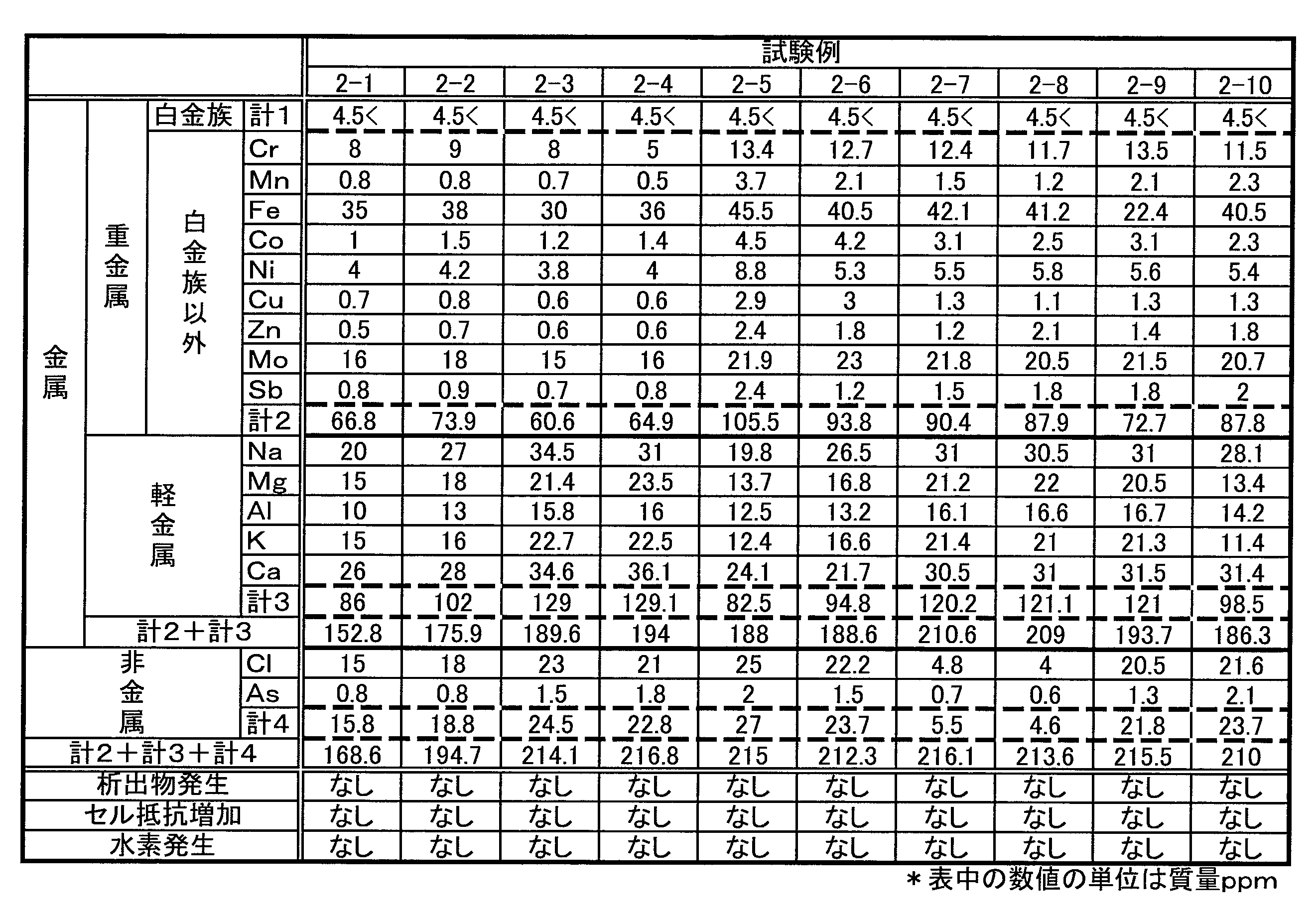
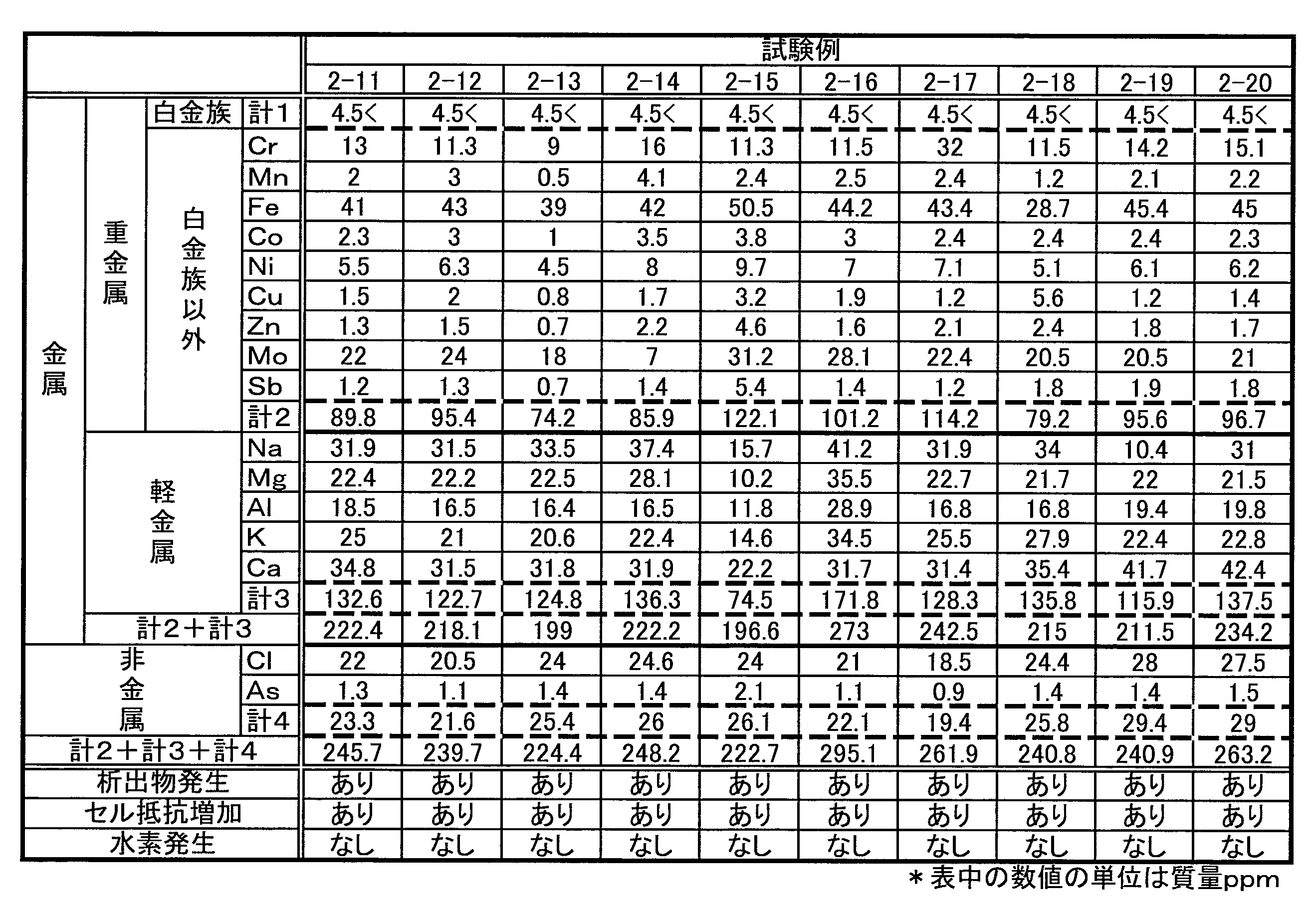
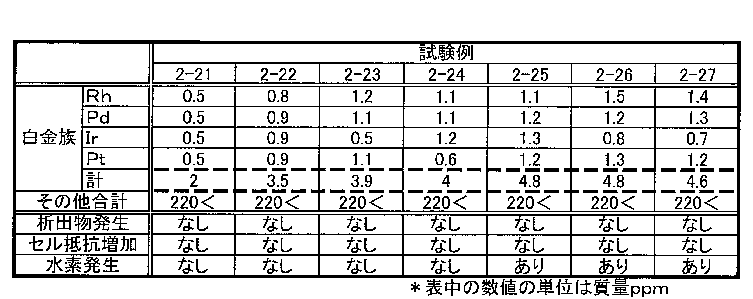
試験例1の結果から、各不純物元素イオンのうち、水素の発生を促進するものを特定するために、不純物元素イオンを金属元素と非金属元素とに分類した。さらに、金属元素を重金属元素と軽金属元素とに、重金属元素とそれ以外とに分類した。そして、各分類の元素イオンの合計濃度が異なる複数の電解液を用意し、いずれの分類が水素の発生を促進するかを検討した。本試験例に用いた各RF電解液の不純物元素イオンの濃度を表2から表4に示す。各表中の数値は、濃度(質量ppm)を表す。なお、不純物元素イオンの濃度の調整方法、および、充放電条件は試験例1と同様である。 <Test Example 2>
From the results of Test Example 1, in order to identify the impurity element ions that promote the generation of hydrogen, the impurity element ions were classified into metallic elements and nonmetallic elements. Furthermore, the metal elements were classified into heavy metal elements and light metal elements, and heavy metal elements and others. Then, a plurality of electrolytic solutions having different total concentrations of element ions of each classification were prepared, and which classification promoted the generation of hydrogen was examined. Tables 2 to 4 show the concentration of impurity element ions in each RF electrolyte solution used in this test example. The numerical value in each table | surface represents a density | concentration (mass ppm). The method for adjusting the concentration of impurity element ions and the charge / discharge conditions are the same as in Test Example 1.
・白金族元素イオンの合計濃度が4.5質量ppm以下であれば、水素の発生を抑制できる。
・析出物の発生に関与する不純物元素イオンの合計濃度が220質量ppm以下であると、析出物の発生を抑制できる。
・析出物の発生に関与する不純物元素イオンのうち、金属元素イオンの合計濃度は195質量ppm以下が好ましい(例えば、試験例2-4など参照)。
・析出物の発生に関与する不純物元素イオンのうち、非金属元素イオンの合計濃度は21質量ppm以下が好ましい(例えば、試験例1-2など参照)。
・析出物の発生に関与する不純物元素イオンのうち、重金属元素イオンの合計濃度は85質量ppm以下が好ましい(例えば、試験例1-2と試験例1-3とを比較参照)。
・析出物の発生に関与する不純物元素イオンのうち、軽金属元素イオンの合計濃度は120質量ppm以下が好ましい(例えば、試験例1-2と試験例1-3とを比較参照)。
・析出物の発生に関与する不純物元素イオンのうち、重金属元素イオンの合計濃度は85質量ppm以下、かつ、軽金属元素イオンの合計濃度は120質量ppm以下が好ましい(例えば、試験例2-2を参照)。
・不純物元素イオンのそれぞれをみた場合、以下が好ましい(例えば、表1参照。
(1)Rhイオン:1質量ppm以下、(2)Pdイオン:1質量ppm以下、(3)Irイオン:1質量ppm以下、(4)Ptイオン:1質量ppm以下(5)Crイオン:10質量ppm以下、(6)Mnイオン:1質量ppm以下、(7)Feイオン:40質量ppm以下、(8)Coイオン:2質量ppm以下、(9)Niイオン:5質量ppm以下、(10)Cuイオン:1質量ppm以下、(11)Znイオン:1質量ppm以下、(12)Moイオン:20質量ppm以下、(13)Sbイオン:1質量ppm以下、(14)Naイオン:30質量ppm以下、(15)Mgイオン:20質量ppm以下、(16)Alイオン:15質量ppm以下、(17)Kイオン:20質量ppm以下、(18)Caイオン:30質量ppm以下、(19)Clイオン:20質量ppm以下、(20)Asイオン:1質量ppm以下 Further, from Table 1 to Table 4, the following can be understood.
-Generation | occurrence | production of hydrogen can be suppressed if the total density | concentration of platinum group element ion is 4.5 mass ppm or less.
-Generation | occurrence | production of a precipitate can be suppressed as the total density | concentration of the impurity element ion concerned with generation | occurrence | production of a precipitate is 220 mass ppm or less.
Of the impurity element ions involved in the generation of precipitates, the total concentration of metal element ions is preferably 195 mass ppm or less (see, for example, Test Example 2-4).
Of the impurity element ions involved in the generation of precipitates, the total concentration of nonmetallic element ions is preferably 21 ppm by mass or less (see, for example, Test Example 1-2).
Of the impurity element ions involved in the generation of precipitates, the total concentration of heavy metal element ions is preferably 85 ppm by mass or less (for example, compare Test Example 1-2 and Test Example 1-3).
Of the impurity element ions involved in the generation of precipitates, the total concentration of light metal element ions is preferably 120 ppm by mass or less (for example, compare Test Example 1-2 and Test Example 1-3).
Of the impurity element ions involved in the generation of precipitates, the total concentration of heavy metal element ions is preferably 85 mass ppm or less, and the total concentration of light metal element ions is preferably 120 mass ppm or less (for example, test example 2-2 reference).
-When each of the impurity element ions is viewed, the following is preferable (for example, see Table 1).
(1) Rh ion: 1 mass ppm or less, (2) Pd ion: 1 mass ppm or less, (3) Ir ion: 1 mass ppm or less, (4) Pt ion: 1 mass ppm or less (5) Cr ion: 10 Mass ppm or less, (6) Mn ion: 1 mass ppm or less, (7) Fe ion: 40 mass ppm or less, (8) Co ion: 2 mass ppm or less, (9) Ni ion: 5 mass ppm or less, (10 ) Cu ion: 1 mass ppm or less, (11) Zn ion: 1 mass ppm or less, (12) Mo ion: 20 mass ppm or less, (13) Sb ion: 1 mass ppm or less, (14) Na ion: 30 mass ppm or less, (15) Mg ion: 20 mass ppm or less, (16) Al ion: 15 mass ppm or less, (17) K ion: 20 mass ppm or less, (18) Ca ion: 30 mass pm or less, (19) Cl ions: 20 ppm by mass or less, (20) As ion: 1 ppm by mass or less

(付記1)
白金族元素イオンの合計濃度が4.5質量ppm以下のRF電解液において、白金族元素イオンが、次の(a)および(b)の少なくとも一方を満たすレドックスフロー電池用電解液。
(a)9族元素イオンの合計濃度が2質量ppm以下
(b)10族元素イオンの合計濃度が2質量ppm以下 Regarding the above description, the following items are further disclosed.
(Appendix 1)
An electrolyte solution for a redox flow battery, wherein a platinum group element ion satisfies at least one of the following (a) and (b) in an RF electrolyte solution having a total concentration of platinum group element ions of 4.5 ppm by mass or less.
(A) Total concentration of group 9 element ions is 2 mass ppm or less (b) Total concentration of group 10 element ions is 2 mass ppm or less
電池反応の際に析出物の発生に関与する不純物元素イオンの合計濃度が220質量ppm以下であり、かつ、白金族元素イオンの合計濃度が4.5質量ppm以下であり、
析出物の発生に関与する不純物元素イオンと、白金族元素イオンとを合わせた群に含まれる元素イオンを、9族に属する元素イオンと、10族に属する元素イオンと、9族に属する元素イオンおよび10族に属する元素イオン以外の元素イオンとに分類した場合に、下記(c)から(e)の少なくとも1つを満たすレドックスフロー電池用電解液。
(c)9族に属する元素イオンの合計濃度が4質量ppm以下
(d)10族に属する元素イオンの合計濃度が7質量ppm以下
(e)9族に属する元素イオンおよび10族に属する元素イオン以外の元素イオンの合計濃度が190質量ppm以下 (Appendix 2)
The total concentration of impurity element ions involved in the generation of precipitates during the battery reaction is 220 mass ppm or less, and the total concentration of platinum group element ions is 4.5 mass ppm or less,
Element ions included in the group of impurity element ions involved in the generation of precipitates and platinum group element ions are group 9 element ions, group 10 element ions, and group 9 element ions. And an electrolyte for a redox flow battery satisfying at least one of the following (c) to (e) when classified into element ions other than element ions belonging to Group 10.
(C) Total concentration of element ions belonging to group 9 is 4 mass ppm or less (d) Total concentration of element ions belonging to group 10 is 7 mass ppm or less (e) Element ions belonging to group 9 and element ions belonging to group 10 The total concentration of other element ions is 190 mass ppm or less
100 電池セル
101 隔膜 102 正極セル 103 負極セル
104 正極電極 105 負極電極
106 正極用タンク 107 負極用タンク
108~111 配管
112,113 ポンプ 1 Redox flow battery (RF battery)
DESCRIPTION OF
Claims (4)
- 白金族元素イオンの合計濃度が4.5質量ppm以下であるレドックスフロー電池用電解液。 Electrolytic solution for redox flow battery having a total concentration of platinum group element ions of 4.5 mass ppm or less.
- 前記白金族元素イオンの濃度が、下記(1)から(4)の少なくとも一つを満たす請求項1に記載のレドックスフロー電池用電解液。
(1)ロジウムイオンの濃度が1質量ppm以下
(2)パラジウムイオンの濃度が1質量ppm以下
(3)イリジウムイオンの濃度が1質量ppm以下
(4)白金イオンの濃度が1質量ppm以下 2. The redox flow battery electrolyte solution according to claim 1, wherein a concentration of the platinum group element ions satisfies at least one of the following (1) to (4).
(1) Rhodium ion concentration is 1 mass ppm or less (2) Palladium ion concentration is 1 mass ppm or less (3) Iridium ion concentration is 1 mass ppm or less (4) Platinum ion concentration is 1 mass ppm or less - バナジウムイオンの濃度が1mol/L以上3mol/L以下、フリーの硫酸の濃度が1mol/L以上4mol/L以下、リン酸の濃度が1.0×10-4mol/L以上7.1×10-1mol/L以下、アンモニウムの濃度が20質量ppm以下、ケイ素の濃度が40質量ppm以下である請求項1又は請求項2に記載のレドックスフロー電池用電解液。 The concentration of vanadium ions is 1 mol / L or more and 3 mol / L or less, the concentration of free sulfuric acid is 1 mol / L or more and 4 mol / L or less, and the concentration of phosphoric acid is 1.0 × 10 −4 mol / L or more and 7.1 × 10 The electrolyte solution for redox flow batteries according to claim 1 or 2, wherein -1 mol / L or less, the ammonium concentration is 20 mass ppm or less, and the silicon concentration is 40 mass ppm or less.
- 請求項1から請求項3のいずれか1項に記載のレドックスフロー電池用電解液を備えるレドックスフロー電池。 A redox flow battery comprising the redox flow battery electrolyte solution according to any one of claims 1 to 3.
Priority Applications (9)
| Application Number | Priority Date | Filing Date | Title |
|---|---|---|---|
| AU2013392798A AU2013392798B2 (en) | 2013-06-21 | 2013-08-07 | Electrolyte for redox flow battery and redox flow battery |
| US14/422,785 US9391340B2 (en) | 2013-06-21 | 2013-08-07 | Electrolyte for redox flow battery and redox flow battery |
| EP13887572.9A EP2876719B1 (en) | 2013-06-21 | 2013-08-07 | Redox flow battery including an electrolyte and the use of an electrolyte in a redox flow battery |
| ES13887572.9T ES2603427T3 (en) | 2013-06-21 | 2013-08-07 | Redox flow battery that includes an electrolyte and use of an electrolyte in a redox flow battery |
| JP2014524191A JP5590512B1 (en) | 2013-06-21 | 2013-08-07 | Redox flow battery electrolyte and redox flow battery |
| CN201380043939.XA CN105283995B (en) | 2013-06-21 | 2013-08-07 | Redox flow battery electrolytic solution and redox flow batteries |
| KR1020157004129A KR101516148B1 (en) | 2013-06-21 | 2013-08-07 | Electrolyte for redox flow battery and redox flow battery |
| TW103127100A TWI518960B (en) | 2013-06-21 | 2014-08-07 | Redox flow battery electrolyte, and redox flow battery |
| IN1169DEN2015 IN2015DN01169A (en) | 2013-06-21 | 2015-02-12 |
Applications Claiming Priority (2)
| Application Number | Priority Date | Filing Date | Title |
|---|---|---|---|
| JP2013-131101 | 2013-06-21 | ||
| JP2013131101 | 2013-06-21 |
Publications (1)
| Publication Number | Publication Date |
|---|---|
| WO2014203410A1 true WO2014203410A1 (en) | 2014-12-24 |
Family
ID=52104171
Family Applications (1)
| Application Number | Title | Priority Date | Filing Date |
|---|---|---|---|
| PCT/JP2013/071427 WO2014203410A1 (en) | 2013-06-21 | 2013-08-07 | Electrolyte for redox flow battery and redox flow battery |
Country Status (10)
| Country | Link |
|---|---|
| US (1) | US9391340B2 (en) |
| EP (2) | EP3082187A1 (en) |
| JP (1) | JP5590512B1 (en) |
| KR (1) | KR101516148B1 (en) |
| CN (1) | CN105283995B (en) |
| AU (1) | AU2013392798B2 (en) |
| ES (1) | ES2603427T3 (en) |
| IN (1) | IN2015DN01169A (en) |
| TW (1) | TWI518960B (en) |
| WO (1) | WO2014203410A1 (en) |
Cited By (2)
| Publication number | Priority date | Publication date | Assignee | Title |
|---|---|---|---|---|
| JP6153100B1 (en) * | 2016-07-26 | 2017-06-28 | 住友電気工業株式会社 | ELECTROLYTE SOLUTION FOR ELECTROLYTIC SOLUTION BATTERY AND ELECTROLYTE SOLUTION DISPERSION BATTERY SYSTEM |
| US11791488B2 (en) | 2016-07-26 | 2023-10-17 | Sumitomo Electric Industries, Ltd. | Flow battery system |
Families Citing this family (5)
| Publication number | Priority date | Publication date | Assignee | Title |
|---|---|---|---|---|
| KR102354666B1 (en) | 2014-08-01 | 2022-01-24 | 스미토모덴키고교가부시키가이샤 | Electrolyte for redox flow battery and redox flow battery system |
| US10333164B2 (en) | 2016-10-07 | 2019-06-25 | Vionx Energy Corporation | Electrochemical-based purification of electrolyte solutions, and related systems and methods |
| EP3734733A1 (en) * | 2017-12-27 | 2020-11-04 | Showa Denko K.K. | Redox flow battery |
| CN111433957A (en) * | 2017-12-27 | 2020-07-17 | 昭和电工株式会社 | Redox flow battery |
| CN117080491B (en) * | 2023-10-18 | 2024-02-09 | 液流储能科技有限公司 | Purification method of electrolyte of flow battery |
Citations (5)
| Publication number | Priority date | Publication date | Assignee | Title |
|---|---|---|---|---|
| JPH03192662A (en) * | 1989-12-21 | 1991-08-22 | Chiyoda Corp | Cell capacity recovery method for redox-flow cell |
| JPH06260204A (en) * | 1993-03-01 | 1994-09-16 | Sumitomo Electric Ind Ltd | Electrolyte circulating type battery with electrolyte reconditioner |
| JPH08148177A (en) * | 1994-11-17 | 1996-06-07 | Kashimakita Kyodo Hatsuden Kk | Manufacture of vanadium electrolyte of high purity |
| JP2002367657A (en) * | 2001-06-07 | 2002-12-20 | Sumitomo Electric Ind Ltd | Electrolyte for redox flow cell, and redox flow cell |
| JP2011233372A (en) | 2010-04-27 | 2011-11-17 | Sumitomo Electric Ind Ltd | Redox flow battery |
Family Cites Families (12)
| Publication number | Priority date | Publication date | Assignee | Title |
|---|---|---|---|---|
| JPS60115174A (en) | 1983-11-25 | 1985-06-21 | Mitsui Eng & Shipbuild Co Ltd | Method of preparing solution for redox-flow battery |
| JPH0679491B2 (en) | 1988-02-04 | 1994-10-05 | 千代田化工建設株式会社 | Method for preparing redox flow battery electrolyte |
| JPH0878042A (en) | 1994-09-01 | 1996-03-22 | Sumitomo Electric Ind Ltd | Manufacture of electrolyte of redox flow type cell |
| DE69730980T2 (en) | 1996-07-31 | 2006-02-23 | Nikken Chemicals Co., Ltd. | 6-PHENYLTETRAHYDRO-1,3-OXAZIN-2-ON DERIVATIVES AND MEDICAL COMPOSITIONS CONTAINING THEY |
| AU2003902298A0 (en) * | 2003-05-12 | 2003-05-29 | Clean Teq Pty Ltd | A method for producing an electrolytic solution containing vanadium |
| WO2010065938A1 (en) * | 2008-12-05 | 2010-06-10 | Deeya Energy Technologies, Inc. | Preparation of electrolytes for redox flow batteries |
| CN102460812B (en) | 2009-05-28 | 2014-12-31 | 艾默吉电力系统股份有限公司 | Preparation of flow cell battery electrolytes from raw materials |
| JP5713186B2 (en) | 2010-03-12 | 2015-05-07 | 住友電気工業株式会社 | Redox flow battery |
| ES2413095T3 (en) | 2010-03-12 | 2013-07-15 | Sumitomo Electric Industries, Ltd. | Redox flow battery |
| JP5007849B1 (en) | 2011-03-25 | 2012-08-22 | 住友電気工業株式会社 | Redox flow battery and operation method thereof |
| WO2013054921A1 (en) | 2011-10-14 | 2013-04-18 | 株式会社ギャラキシー | Vanadium electrolyte, production method therefor, and production device therefor |
| TW201327993A (en) | 2011-12-30 | 2013-07-01 | Soon-Myoung Wy | Electrode for redox flow battery, method for manufacturing the same, electrolyte for redox flow battery, method for manufacturing the same, selective ion concentration meter for electrolyte, method for measuring selective ion concentration |
-
2013
- 2013-08-07 US US14/422,785 patent/US9391340B2/en active Active
- 2013-08-07 EP EP16172571.8A patent/EP3082187A1/en not_active Withdrawn
- 2013-08-07 EP EP13887572.9A patent/EP2876719B1/en active Active
- 2013-08-07 WO PCT/JP2013/071427 patent/WO2014203410A1/en active Application Filing
- 2013-08-07 ES ES13887572.9T patent/ES2603427T3/en active Active
- 2013-08-07 AU AU2013392798A patent/AU2013392798B2/en active Active
- 2013-08-07 KR KR1020157004129A patent/KR101516148B1/en active IP Right Grant
- 2013-08-07 JP JP2014524191A patent/JP5590512B1/en active Active
- 2013-08-07 CN CN201380043939.XA patent/CN105283995B/en active Active
-
2014
- 2014-08-07 TW TW103127100A patent/TWI518960B/en active
-
2015
- 2015-02-12 IN IN1169DEN2015 patent/IN2015DN01169A/en unknown
Patent Citations (5)
| Publication number | Priority date | Publication date | Assignee | Title |
|---|---|---|---|---|
| JPH03192662A (en) * | 1989-12-21 | 1991-08-22 | Chiyoda Corp | Cell capacity recovery method for redox-flow cell |
| JPH06260204A (en) * | 1993-03-01 | 1994-09-16 | Sumitomo Electric Ind Ltd | Electrolyte circulating type battery with electrolyte reconditioner |
| JPH08148177A (en) * | 1994-11-17 | 1996-06-07 | Kashimakita Kyodo Hatsuden Kk | Manufacture of vanadium electrolyte of high purity |
| JP2002367657A (en) * | 2001-06-07 | 2002-12-20 | Sumitomo Electric Ind Ltd | Electrolyte for redox flow cell, and redox flow cell |
| JP2011233372A (en) | 2010-04-27 | 2011-11-17 | Sumitomo Electric Ind Ltd | Redox flow battery |
Non-Patent Citations (1)
| Title |
|---|
| See also references of EP2876719A4 * |
Cited By (6)
| Publication number | Priority date | Publication date | Assignee | Title |
|---|---|---|---|---|
| JP6153100B1 (en) * | 2016-07-26 | 2017-06-28 | 住友電気工業株式会社 | ELECTROLYTE SOLUTION FOR ELECTROLYTIC SOLUTION BATTERY AND ELECTROLYTE SOLUTION DISPERSION BATTERY SYSTEM |
| JP2018018640A (en) * | 2016-07-26 | 2018-02-01 | 住友電気工業株式会社 | Electrolyte for electrolyte flow type battery and electrolyte flow type battery system |
| WO2018020786A1 (en) * | 2016-07-26 | 2018-02-01 | 住友電気工業株式会社 | Electrolyte for electrolyte circulation-type battery, and electrolyte circulation-type battery system |
| WO2018020787A1 (en) * | 2016-07-26 | 2018-02-01 | 住友電気工業株式会社 | Rechargeable battery system, and electrolyte |
| US11233253B2 (en) | 2016-07-26 | 2022-01-25 | Sumitomo Electric Industries, Ltd. | Electrolyte for flow battery and flow battery system |
| US11791488B2 (en) | 2016-07-26 | 2023-10-17 | Sumitomo Electric Industries, Ltd. | Flow battery system |
Also Published As
| Publication number | Publication date |
|---|---|
| TWI518960B (en) | 2016-01-21 |
| EP2876719B1 (en) | 2016-11-02 |
| EP2876719A4 (en) | 2015-08-05 |
| AU2013392798B2 (en) | 2017-09-28 |
| CN105283995B (en) | 2017-07-14 |
| KR101516148B1 (en) | 2015-05-04 |
| US20150228997A1 (en) | 2015-08-13 |
| AU2013392798A1 (en) | 2015-03-05 |
| JP5590512B1 (en) | 2014-09-17 |
| ES2603427T3 (en) | 2017-02-27 |
| CN105283995A (en) | 2016-01-27 |
| IN2015DN01169A (en) | 2015-06-26 |
| KR20150034271A (en) | 2015-04-02 |
| TW201513429A (en) | 2015-04-01 |
| EP2876719A1 (en) | 2015-05-27 |
| EP3082187A1 (en) | 2016-10-19 |
| JPWO2014203410A1 (en) | 2017-02-23 |
| US9391340B2 (en) | 2016-07-12 |
Similar Documents
| Publication | Publication Date | Title |
|---|---|---|
| JP5590513B1 (en) | Redox flow battery electrolyte and redox flow battery | |
| JP5590512B1 (en) | Redox flow battery electrolyte and redox flow battery | |
| WO2014203408A1 (en) | Electrolyte for redox flow battery and redox flow battery | |
| US11233253B2 (en) | Electrolyte for flow battery and flow battery system | |
| JP5590514B1 (en) | Redox flow battery electrolyte and redox flow battery | |
| TWI518962B (en) | Redox flow battery electrolyte, and redox flow battery | |
| US11791488B2 (en) | Flow battery system |
Legal Events
| Date | Code | Title | Description |
|---|---|---|---|
| WWE | Wipo information: entry into national phase |
Ref document number: 201380043939.X Country of ref document: CN |
|
| ENP | Entry into the national phase |
Ref document number: 2014524191 Country of ref document: JP Kind code of ref document: A |
|
| ENP | Entry into the national phase |
Ref document number: 20157004129 Country of ref document: KR Kind code of ref document: A |
|
| 121 | Ep: the epo has been informed by wipo that ep was designated in this application |
Ref document number: 13887572 Country of ref document: EP Kind code of ref document: A1 |
|
| REEP | Request for entry into the european phase |
Ref document number: 2013887572 Country of ref document: EP |
|
| WWE | Wipo information: entry into national phase |
Ref document number: 14422785 Country of ref document: US Ref document number: 2013887572 Country of ref document: EP |
|
| ENP | Entry into the national phase |
Ref document number: 2013392798 Country of ref document: AU Date of ref document: 20130807 Kind code of ref document: A |
|
| NENP | Non-entry into the national phase |
Ref country code: DE |