WO2014200196A1 - 철강용 rfid 태그 장치 - Google Patents
철강용 rfid 태그 장치 Download PDFInfo
- Publication number
- WO2014200196A1 WO2014200196A1 PCT/KR2014/004478 KR2014004478W WO2014200196A1 WO 2014200196 A1 WO2014200196 A1 WO 2014200196A1 KR 2014004478 W KR2014004478 W KR 2014004478W WO 2014200196 A1 WO2014200196 A1 WO 2014200196A1
- Authority
- WO
- WIPO (PCT)
- Prior art keywords
- steel
- rfid tag
- tag device
- unit
- rfid
- Prior art date
- Legal status (The legal status is an assumption and is not a legal conclusion. Google has not performed a legal analysis and makes no representation as to the accuracy of the status listed.)
- Ceased
Links
Images


Classifications
-
- G—PHYSICS
- G06—COMPUTING OR CALCULATING; COUNTING
- G06K—GRAPHICAL DATA READING; PRESENTATION OF DATA; RECORD CARRIERS; HANDLING RECORD CARRIERS
- G06K19/00—Record carriers for use with machines and with at least a part designed to carry digital markings
- G06K19/06—Record carriers for use with machines and with at least a part designed to carry digital markings characterised by the kind of the digital marking, e.g. shape, nature, code
- G06K19/067—Record carriers with conductive marks, printed circuits or semiconductor circuit elements, e.g. credit or identity cards also with resonating or responding marks without active components
- G06K19/07—Record carriers with conductive marks, printed circuits or semiconductor circuit elements, e.g. credit or identity cards also with resonating or responding marks without active components with integrated circuit chips
- G06K19/077—Constructional details, e.g. mounting of circuits in the carrier
- G06K19/07749—Constructional details, e.g. mounting of circuits in the carrier the record carrier being capable of non-contact communication, e.g. constructional details of the antenna of a non-contact smart card
- G06K19/07771—Constructional details, e.g. mounting of circuits in the carrier the record carrier being capable of non-contact communication, e.g. constructional details of the antenna of a non-contact smart card the record carrier comprising means for minimising adverse effects on the data communication capability of the record carrier, e.g. minimising Eddy currents induced in a proximate metal or otherwise electromagnetically interfering object
-
- G—PHYSICS
- G06—COMPUTING OR CALCULATING; COUNTING
- G06K—GRAPHICAL DATA READING; PRESENTATION OF DATA; RECORD CARRIERS; HANDLING RECORD CARRIERS
- G06K19/00—Record carriers for use with machines and with at least a part designed to carry digital markings
- G06K19/06—Record carriers for use with machines and with at least a part designed to carry digital markings characterised by the kind of the digital marking, e.g. shape, nature, code
- G06K19/067—Record carriers with conductive marks, printed circuits or semiconductor circuit elements, e.g. credit or identity cards also with resonating or responding marks without active components
- G06K19/07—Record carriers with conductive marks, printed circuits or semiconductor circuit elements, e.g. credit or identity cards also with resonating or responding marks without active components with integrated circuit chips
- G06K19/077—Constructional details, e.g. mounting of circuits in the carrier
-
- G—PHYSICS
- G06—COMPUTING OR CALCULATING; COUNTING
- G06K—GRAPHICAL DATA READING; PRESENTATION OF DATA; RECORD CARRIERS; HANDLING RECORD CARRIERS
- G06K19/00—Record carriers for use with machines and with at least a part designed to carry digital markings
- G06K19/06—Record carriers for use with machines and with at least a part designed to carry digital markings characterised by the kind of the digital marking, e.g. shape, nature, code
- G06K19/067—Record carriers with conductive marks, printed circuits or semiconductor circuit elements, e.g. credit or identity cards also with resonating or responding marks without active components
- G06K19/07—Record carriers with conductive marks, printed circuits or semiconductor circuit elements, e.g. credit or identity cards also with resonating or responding marks without active components with integrated circuit chips
-
- H—ELECTRICITY
- H01—ELECTRIC ELEMENTS
- H01Q—ANTENNAS, i.e. RADIO AERIALS
- H01Q1/00—Details of, or arrangements associated with, antennas
- H01Q1/12—Supports; Mounting means
- H01Q1/1207—Supports; Mounting means for fastening a rigid aerial element
-
- H—ELECTRICITY
- H01—ELECTRIC ELEMENTS
- H01Q—ANTENNAS, i.e. RADIO AERIALS
- H01Q1/00—Details of, or arrangements associated with, antennas
- H01Q1/12—Supports; Mounting means
- H01Q1/22—Supports; Mounting means by structural association with other equipment or articles
- H01Q1/2208—Supports; Mounting means by structural association with other equipment or articles associated with components used in interrogation type services, i.e. in systems for information exchange between an interrogator/reader and a tag/transponder, e.g. in Radio Frequency Identification [RFID] systems
- H01Q1/2225—Supports; Mounting means by structural association with other equipment or articles associated with components used in interrogation type services, i.e. in systems for information exchange between an interrogator/reader and a tag/transponder, e.g. in Radio Frequency Identification [RFID] systems used in active tags, i.e. provided with its own power source or in passive tags, i.e. deriving power from RF signal
-
- H—ELECTRICITY
- H01—ELECTRIC ELEMENTS
- H01Q—ANTENNAS, i.e. RADIO AERIALS
- H01Q1/00—Details of, or arrangements associated with, antennas
- H01Q1/12—Supports; Mounting means
- H01Q1/22—Supports; Mounting means by structural association with other equipment or articles
- H01Q1/24—Supports; Mounting means by structural association with other equipment or articles with receiving set
-
- H—ELECTRICITY
- H01—ELECTRIC ELEMENTS
- H01Q—ANTENNAS, i.e. RADIO AERIALS
- H01Q9/00—Electrically-short antennas having dimensions not more than twice the operating wavelength and consisting of conductive active radiating elements
- H01Q9/04—Resonant antennas
- H01Q9/16—Resonant antennas with feed intermediate between the extremities of the antenna, e.g. centre-fed dipole
- H01Q9/26—Resonant antennas with feed intermediate between the extremities of the antenna, e.g. centre-fed dipole with folded element or elements, the folded parts being spaced apart a small fraction of operating wavelength
- H01Q9/27—Spiral antennas
Definitions
- the present invention relates to an RFID tag antenna that can be recognized even in thick steel products, and more particularly, to an RFID tag that solves a problem of deterioration due to various product stacking shapes when a yard is loaded in steel products.
- RFID Radio Frequency Identification
- the tag operates by the electromagnetic backscattering method, and more particularly, receives the radio wave transmitted through the reader antenna by the RFID tag antenna and converts it to direct current using a rectifier circuit. The converted energy operates the chip and the information of the chip is sent back to the reader through the RFID tag antenna.
- RFID technology When applied to steel logistics, RFID technology has advantages such as simplifying or eliminating the integrated inspection process, constructing crane automation, delivering real-time product information, and reducing product inconsistency.
- FIG. 1 is a view showing a steel product according to the prior art and a general tag attached thereto. As shown in the figure, the tag is attached to the side of the steel product. In particular, the lower the height (T) is applicable to the thinner steel products to the thicker products. The narrower the width (h), the greater the risk of tag breakage during product movement. low.
- Figure 2 is a view showing the classification according to the shape in which the steel products according to the prior art are stacked upon loading the yard.
- the metal RFID tag applied to steel products considers only the attached metal when designing, and does not consider various shapes due to lamination, so performance deterioration occurs in actual applications.
- the recognition is not possible with a general RFID tag antenna.
- the tag product attached to the steel product has a variety of external environment according to the lamination and movement, especially when it is drawn to the outside or has a laminated structure buried RFID tag between the upper plate and the lower plate.
- the RFID tag device for achieving the technical problem is a substrate portion insulated from the steel product, and transmits and receives radio waves, the radiation portion and the substrate portion and the radiating portion is formed of a helical structure and one side of the steel product It is characterized by consisting of the jig attached.
- the RFID tag device for steel has an advantage of overcoming an unrecognition problem occurring when attached to steel products and buried between steel products stacked in various forms and enabling stable transmission and reception.
- FIG. 1 is a view showing a steel product according to the prior art and a general tag attached thereto.
- Figure 2 is a view showing the classification according to the shape in which the steel products according to the prior art are stacked upon loading the yard.
- FIG. 3 is a diagram illustrating classified steel products stacked according to radio waves in order to explain an RFID tag device according to the present invention.
- FIG. 4 is a diagram illustrating a configuration of an RFID tag device according to the present invention.
- FIG. 5 is a view showing a substrate portion of the RFID tag device according to the present invention.
- FIG. 6 is a view showing a radiating part of the RFID tag device according to the present invention.
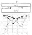
- FIG. 7 is a diagram illustrating input matching characteristics according to various stacking environment changes in the RFID tag device according to the present invention.
- FIG. 3 is a diagram illustrating classified steel products stacked according to radio waves in order to explain an RFID tag device according to the present invention.
- the state in which the steel product 120 is loaded will affect the radio wave incident or radiated.
- the state in which the steel product 120 is loaded is called a radio wave environment.
- the propagation environment is divided into open type and parallel plate transmission linear.
- An open type is a radio wave environment that only considers the impact of steel products 120.
- the parallel plate transmission linear is a radio wave environment in which the upper and lower portions of the steel product 120 to be targeted are surrounded by other steel products 120.
- the electric field is minimized and the magnetic field is maximized due to the boundary condition of radio waves incident or radiated on the conductor surface.
- Radiators such as helical structures or loop structures have excellent magnetic fields.
- FIG. 4 is a diagram illustrating a configuration of an RFID tag device according to the present invention.
- the RFID tag device 110 is attached to the side of the steel product 120 and is insulated from the steel product 120.
- the RFID tag device 110 includes a substrate portion 430 having an RFID IC chip and a line pattern, a radiation portion 420 and a substrate portion 430 and a radiation portion 420 configured to transmit and receive radio waves and have a helical structure. ) Is composed of a jig part 410 is attached to one side to the steel product 120.
- FIG. 5 is a view showing a substrate portion of the RFID tag device according to the present invention.
- FIG. 5 (a) is a view showing a substrate portion of the RFID tag device according to the present invention.
- FIG. 5B is a diagram illustrating a configuration in which the matching unit 432 is further provided in the substrate unit of the RFID tag device according to the present invention.
- the substrate unit 430 may further include a matching unit 432 as necessary in addition to the configuration of the connection unit 440 and the RFID IC chip 431 connected to the radiating unit 420.
- the surface on which the radiating portion 420, the connecting portion 440, and the RFID IC chip 431 are formed on the substrate 430 is called a front surface, and the opposite surface is called a rear surface.
- Meander line structure means that the line of the antenna has a serpentine shape to reduce the length of the antenna, and has various forms. Meander lines are widely used as transmission lines to implement RF devices or as matching inductors for RF circuit matching.
- RF transmission lines such as microstrip lines
- RF transmission lines are widely used to realize passive components for RF, which are composed of capacitors and inductors. Passive devices for RF have a fairly large footprint over the entire RF circuit.
- meander-type transmission lines have been widely used. By using meander-type lines, the length of the transmission line constituting the RF device is greatly reduced.
- the meander line is also widely used as a matching inductor on an RF circuit, and has an advantage of having very few parasitic components compared to a conventional spiral inductor.
- the matching unit 432 may achieve complex conjugate matching with the RFID IC chip 431.
- the RFID IC chip 431 is an active element and has a complex impedance at its output.
- Complex conjugate matching refers to a design method that minimizes the reflected signal by canceling and designing a sign of an imaginary value between two terminals to be connected differently.
- the frequency needs to be additionally changed after the impedance matching of the radiator 420 to a specific frequency.
- the required RF frequency is different from country to country, all of the radiators 420 must be manufactured differently. If the radiating parts 420 are all manufactured at different frequencies, a large mold cost will be generated.
- the matching unit 432 may be further provided so that the radiator 420 may be re-manufactured by adjusting to another frequency.
- FIG. 6 is a view showing a radiating part of the RFID tag device according to the present invention.
- the radiating part 420 has one or more conductive lines of one or more helical structures 421 connected to the substrate part 430.
- the helical structure 421 is a spiral of antenna elements.
- the helical structure 421 has a monopole type and a dipole type.
- the monopole method uses a conductor plane as a ground plane.
- the dipole method is a structure having a conductive line having a helical structure 421 from the center to both sides.
- the input impedance may have a drastic change depending on the shape of the conductor surface. Therefore, it is appropriate that the radiator 420 has a dipole type helical structure 421.
- the radiator 420 is designed to achieve complex conjugate matching with a design frequency.
- One or more conductive wires connected to the substrate portion 430 have a helical structure 421, one side of each conductive wire is connected to the connection portion 440, and the other side is bent to be bent in the direction of the connection portion 440.
- the bent structure 422 stabilizes the impedance through the coupling with the steel product 120.
- the shape of the conductor of the helical structure 421 is formed in various forms including polygons such as circles, ovals and triangles, rectangles, squares, and pentagons. If the structure 422 bent in the direction of the connecting portion 440 is a structure that induces a propagation environment and coupling regardless of the bending direction and deformation can achieve the above object.
- a cylinder means a three-dimensionally enclosed curved surface formed by a straight line turning around a straight line parallel to him.
- An antenna cylinder means a hollow cylindrical antenna with a hollow shape.
- the rod means a round circumference and the antenna rod means a round circumference antenna.
- the number of winding wires of the conductive wire having the helical structure 421 in the radiating part 420 is determined according to the material of the jig part 410 and the input impedance of the RFID IC chip 431.
- the number of winding wires refers to the number of windings of the conductor having the helical structure 421.
- the radiating part 420 has a feature that is not electrically connected to the steel product 120 to be attached.
- the radiating unit 420 has a characteristic that by implementing the radiating unit 420 depending only on the magnetic field, the input matching is not sensitively changed even in the change of the surrounding environment and can ensure stable performance.
- the jig portion 410 has a sealed structure that constitutes the substrate portion 430 and the radiating portion 420 therein, or a portion of the substrate portion 430 and the radiating portion 420 has an open structure.
- Jig portion 410 may have a variety of forms, including hexahedral, cylindrical and ellipsoidal.
- the jig unit 410 may improve the radiation efficiency of the radiator 420 when using a material having a high dielectric constant or high permeability. For example, among metals, there are gold, silver, copper, aluminum, iron and alloys.
- the jig part 410 is made of a metal material in contact with the steel product 120 by heat bonding or plastic bonding, or bonding or taping, or by inserting a groove and inserting a structural coupling to move and impact Ensure stable attachment.
- FIG. 7 is a diagram illustrating input matching characteristics according to various stacking environment changes in the RFID tag device according to the present invention.
- the input impedance of the radiator 420 is based on a commercial product and illustrates the change in input matching according to the depth W buried between the steel products 120.
- the RFID tag device 110 may obtain a complex conjugate matching with the chip even with a change in the depth W buried between the steel products 120.
Landscapes
- Engineering & Computer Science (AREA)
- Physics & Mathematics (AREA)
- Computer Hardware Design (AREA)
- Microelectronics & Electronic Packaging (AREA)
- General Physics & Mathematics (AREA)
- Theoretical Computer Science (AREA)
- Electromagnetism (AREA)
- Near-Field Transmission Systems (AREA)
- Aerials With Secondary Devices (AREA)
Abstract
본 발명은, 철강제품에 부착된 태그 제품이 적층 및 이동에 따른 다양한 외부환경을 가지며, 특히 외부로 도출되거나 혹은 위판과 아래 판 사이에 RFID태그가 삽입되는 적층구조를 가질 때, 적층구조의 전파특성을 고려하여 적층구조에서 내부 필드를 여기할 수 있는 다양한 적층환경에 따른 인식불능문제를 극복하고 안정적 송수신이 가능하게 하는 RFID 태그를 제공한다.
Description
본 발명은 두꺼운 철강제품에서도 인식이 가능한 RFID 태그 안테나에 관한 것으로서, 특히 철강제품의 야드 적재 시 다양한 제품적층 형상으로 인한 성능저하의 문제를 해결한 RFID 태그에 관한 것이다.
RFID(Radio Frequency Identification) 기술은 사물에 소형 칩과 안테나로 구성된 태그를 부착하여 무선으로 사물의 ID를 인식하여 정보를 수집하고 이를 통해 위치 및 상태를 제공한다. 이 중 태그는 전자기 역산란방식으로 동작하며, 더욱 상세히는 리더 안테나를 통해서 송신된 전파를 RFID 태그 안테나로 수신한 후 정류 회로를 이용하여 이를 직류로 변환한다. 변환된 에너지는 칩을 동작시키고 칩의 정보는 다시 RFID 태그 안테나를 통해서 리더기로 보내지게 된다.
이러한 RFID 기술을 철강제품에 적용한 유통 및 물류관리 통합관리 시스템이 개발되고 있다. RFID 기술을 철강물류유통에 적용할 경우 통합검수과정 간소화 또는 생략, 크레인 자동화 구축, 실시간 제품정보 전달가능 및 제품 불일치률 감소 등의 장점을 가진다.
도 1은 종래기술에 따른 철강제품 및 이에 부착되는 일반적인 태그를 도시한 도면이다. 도시된 바와 같이 태그는 철강제품의 측면에 부착되며, 특히 높이(T)가 낮을수록 얇은 두께의 철강제품에서부터 두꺼운 제품까지 다양하게 적용가능하며 폭(h)이 좁을수록 제품이동시 태그파손의 위험이 낮다.
도 2는 종래기술에 따른 철강제품이 야드 적재 시 적층되는 형상에 따른 분류를 도시한 도면이다. 일반적으로 철강제품에 적용되는 메탈 RFID 태그는 설계 시 부착된 메탈만을 고려하며 적층으로 인한 다양한 형상을 고려하지 않기 때문에 실제 적용에서 성능열화가 일어나며 특히 Case E와 같이 상판과 하판이 도출되어 부착된 태그가 묻히는 구조의 경우 일반적인 RFID 태그 안테나로는 인식이 불가하다는 문제점이 있었다.
또한, 일반적인 메탈 태그들은 부착되는 철강제품을 접지면으로 이용하여 안정적인 방사성능을 구현하지만 이는 철강제품의 임의의 크기 및 다양한 적층환경에서는 정합특성이 민감하게 변화하여 결정적인 성능저하의 원인이 되는 문제점이 있었다.
본 발명이 해결하고자 하는 기술적 과제는, 철강제품에 부착된 태그 제품이 적층 및 이동에 따른 다양한 외부환경을 가지며, 특히 외부로 도출되거나 혹은 위판과 아래 판 사이에 RFID태그가 묻히는 적층구조를 가질 때, 적층구조의 전파특성을 고려하여 적층구조에서 철강제품들 사이에 묻혀도 인식할 수 있는 RFID 태그 장치를 제안하는 것이다.
상기 기술적 과제를 이루기 위한 본 발명에 따른 상기 RFID 태그 장치는 상기 철강제품과 절연된 기판부, 전파를 송수신하며, 헬리컬 구조로 구성된 방사부 및 상기 기판부와 상기 방사부를 감싸고 상기 철강제품에 일측이 부착된 지그부로 구성하는 것을 특징으로 한다.
본 발명에 따른 철강용 RFID 태그 장치는 철강제품에 부착되고, 다양한 형태로 적층된 철강제품들 사이에 묻힌 경우에 발생하는 인식불능문제를 극복하고 안정적 송수신이 가능하게 하는 장점이 있다.
도 1은 종래기술에 따른 철강제품 및 이에 부착되는 일반적인 태그를 도시한 도면이다.
도 2는 종래기술에 따른 철강제품이 야드 적재 시 적층되는 형상에 따른 분류를 도시한 도면이다.
도 3은 본 발명에 따른 RFID 태그 장치를 설명하기 위하여 적층된 철강제품을 전파의 관점에 따라 분류하여 도시한 도면이다.
도 4는 본 발명에 따른 RFID 태그 장치의 구성도를 도시한 도면이다.
도 5는 본 발명에 따른 RFID 태그 장치의 기판부를 도시한 도면이다.
도 6은 본 발명에 따른 RFID 태그 장치의 방사부를 도시한 도면이다.
도 7은 본 발명에 따른 RFID 태그 장치에 있어서 다양한 적층환경변화에 따른 입력정합 특성을 도시한 도면이다.
이하에서는 본 발명의 구체적인 실시 예를 도면을 참조하여 상세히 설명하도록 한다.
도 3은 본 발명에 따른 RFID 태그 장치를 설명하기 위하여 적층된 철강제품을 전파의 관점에 따라 분류하여 도시한 도면이다.
철강제품(120)이 적재된 상태에 따라 입사되거나 방사되는 전파에 영향을 미치게 된다. 철강제품(120)이 적재된 상태를 전파환경이라 한다.
전파환경은 개방형과 평행평판전송선형으로 나뉜다. 개방형은 철강제품(120) 영향만을 고려하는 전파환경이다. 평행평판전송선형은 타켓으로 하는 철강제품(120)의 상부와 하부가 다른 철강제품(120)에 둘러싸여져 있는 전파환경이다. 두 전파환경 모두 도체 표면에 입사 혹은 방사되는 전파가 경계조건에 의해 전기장은 최소화되고, 자기장은 최대화 되는 특징을 가진다. 전파환경에서는 자기장이 우수한 방사체를 사용하는 것이 좋다. 헬리컬 구조 혹은 루프 구조 등의 방사체는 자기장이 우수한 성질을 가지고 있다.
도 4는 본 발명에 따른 RFID 태그 장치의 구성도를 도시한 도면이다.
RFID 태그 장치(110, RFID Tag device)는 철강제품(120) 측면에 부착되며, 철강제품(120)과 절연된다. RFID 태그 장치(110, RFID Tag device)는 RFID IC칩 및 라인 패턴이 있는 기판부(430), 전파를 송수신하며, 헬리컬 구조로 구성된 방사부(420) 및 기판부(430)와 방사부(420)를 감싸고 철강제품(120)에 일측이 부착된 지그부(410)로 구성된다.
도 5는 본 발명에 따른 RFID 태그 장치의 기판부를 도시한 도면이다.
도 5의 (a)는 본 발명에 따른 RFID 태그 장치의 기판부를 도시한 도면이다.
기판부(430)는 방사부(420)와 연결되는 연결부(440) 및 RFID IC칩(431)으로 구성된다.
도 5의 (b)는 본 발명에 따른 RFID 태그 장치의 기판부에 정합부(432)가 더 구비된 구성을 도시한 도면이다.
기판부(430)는 방사부(420)와 연결되는 연결부(440) 및 RFID IC칩(431)의 구성 이외에 필요에 따라서 정합부(432)를 더 구비할 수 있다.
기판부(430)에 방사부(420), 연결부(440) 및 RFID IC칩(431)이 구성된 면을 전면이라 하고, 그 반대면을 후면이라 한다.
기판부(430)는 부착되는 철강제품(120)과 전기적으로 연결되어 있지 않은 특징을 가진다. 기판부(430)의 후면은 지그부(410)의 내부에 부착된다. 기판부(430)의 후면은 철강제품(120)이 위치한 방향의 반대쪽을 제외한 모든 방향에 부착되어도 무방하다. 기판부(430)에 연결된 방사부(420)가 철강제품(120)의 방향을 향하게 되면 방사부(420)에서 방사되는 주파수가 방해를 받게 되어 효율이 떨어질 수 있다.
필요에 따라서 구비하는 정합부(432)는 커패시터와 인덕터 또는 미앤더 라인(Meander line) 구조로 구성된다.
미앤더 라인(Meander line) 구조는 안테나의 길이를 줄이기 위해서 안테나의 라인이 꾸불꾸불 한 모양을 가진 것을 뜻하며, 다양한 형태를 가지고 있다. 미앤더 선로는 RF용 소자를 구현하기 위한 전송선로 혹은 RF 회로 정합을 위한 정합용 인덕터로써 널리 사용된다.
커패시터와 인덕터로 이루어진 RF용 수동소자를 구현하기 위해 마이크로 스트립 선로 등의 RF용 전송선로가 널리 사용된다. RF용 수동소자들은 전체 RF 회로 상에서 상당히 큰 점유면적을 가진다. 효율적인 레이아웃 배치를 통해 이러한 문제점을 해결하기 위해서 미앤더 형태의 전송선로가 널리 사용되어 왔으며, 미앤더 형태의 선로를 사용함으로써 RF 소자를 구성하는 전송선로의 길이는 대폭 축소된다. 상기 미앤더 선로는 RF 회로상의 정합용 인덕터로서도 널리 사용되며, 종래의 스파이럴 인덕터에 비해 기생성분이 매우 적다는 장점을 가진다.
정합부(432)는 RFID IC칩(431)과 복소 공액 정합(Complex Conjugate Matching)을 이룰 수 있다. RFID IC칩(431)은 능동소자로 출력단에 복소 임피던스를 가지게 된다.
임피던스 매칭이란 서로 다른 두 신호선을 연결할 때, 각 신호선의 임피던스 차이에 의해 전송신호가 반사되는 것을 막기 위한 기술로써, 이를 위해 방사부는 RFID IC칩(431)과 복소 공액정합을 이루어야 한다.
복소 공액 정합(Complex Conjugate Matching)이란 연결되는 두 단자간의 허수 값의 부호를 다르게 가지도록 설계하여 상쇄시킴으로써 반사되는 신호를 최소화하는 설계법을 지칭한다.
정합부(432)는 안테나 설계시 복소 공액 정합이 충분하지 못할 경우 이를 보조하는 역할을 한다. .
정합부(432)를 필요에 따라 더 구비하는 이유는 다양한 주파수에 대응하기 위해서이다. 헬리컬 안테나를 이용하여 방사부(420)를 설계주파수와 복소 공액 정합(Complex Conjugate Matching)을 이루도록 설계하게 되면 주파수가 고정되게 된다.
방사부(420)를 특정 주파수에 맞추어 임피던스 매칭을 한 이후에 추가적으로 주파수를 변경해야 하는 경우도 발생할 수 있다. 예를 들면 필요로 하는 RF주파수가 국가마다 다르기 때문에 방사부(420)를 모두 다르게 제작해야 하는 경우이다. 방사부(420)를 모두 다른 주파수로 제작하게 되면 많은 금형비용이 발생하게 된다. 이러한 경우 정합부(432)를 더 구비하여 다른 주파수에 맞출 수 있도록 하여 방사부(420)를 다시 제작해야 하는 문제를 해결할 수 있다.
도 6은 본 발명에 따른 RFID 태그 장치의 방사부를 도시한 도면이다.
방사부(420)는 일측이 기판부(430)와 연결된 1개 이상의 헬리컬 구조(421)의 도선을 가진다. 헬리컬 구조(421)는 안테나 소자(antenna element)가 나선형으로 된 것이다. 헬리컬 구조(421)는 모노폴 방식과 다이폴 방식이 있다.
모노폴 방식은 도체면을 접지면으로 사용하는 구조이다.
다이폴 방식은 중앙에서부터 양쪽으로 헬리컬 구조(421)를 가진 도선을 가지는 구조이다.
모노폴 방식의 경우 입력 임피던스가 도체면의 형상에 따라 급격한 변화를 가지게 되는 단점이 있다. 그러므로 방사부(420)는 다이폴 방식의 헬리컬 구조(421)를 가지는 것이 적절하다. 방사부(420)는 설계주파수와 복소 공액 정합(Complex Conjugate Matching)을 이루도록 설계 한다.
기판부(430)와 연결된 1개 이상의 도선은 헬리컬 구조(421)를 가지며, 각각의 도선의 일측은 연결부(440)와 연결되고, 다른 일측은 연결부(440) 방향으로 꺾이게 하여 꺾인 구조(422)를 가지고 정합 특성을 확보한다. 꺾인 구조(422)는 철강제품(120)과 커플링을 통해 임피던스가 안정화된다. 헬리컬 구조(421)의 도선 형태가 원형, 타원형과 삼각형, 직사각형, 정사각형 및 오각형 등의 다각형을 포함한 다양한 형태로 이루어진다. 연결부(440) 방향으로 꺾인 구조(422)들은 꺾는 방향과 변형에 상관없이 전파환경과 커플링을 유도하는 구조이면 전술한 목적이 달성 가능하다.
이외에도 유전체 혹은 자성체의 성질을 가진 안테나 원통 또는 안테나 봉(423)을 헬리컬 구조(421)의 도선이 감싸는 구조를 가질 수도 있다.
원통이라는 뜻은 하나의 직선이 그와 나란한 직선의 둘레를 한 바퀴 돌아서 생긴 곡면으로 둘러싸인 입체로서 안테나 원통은 속이 비어있는 동그란 통모형의 안테나를 뜻한다.
봉이라는 뜻은 둘레가 둥근 대로서 안테나 봉은 속이 차있는 둘레가 둥근 안테나를 뜻하는 것이다.
방사부(420)내의 헬리컬 구조(421)를 가진 도선의 권선(winding wire) 수는 지그부(410)의 재질 및 RFID IC칩(431)의 입력 임피던스에 따라 결정된다. 권선(winding wire) 수는 헬리컬 구조(421)를 가진 도선이 감겨있는 수를 말한다.
방사부(420)는 부착되는 철강제품(120)과 전기적으로 연결되어 있지 않은 특징을 가진다. 방사부(420)는 자기장에만 의존하는 방사부(420)를 구현함으로써, 주위환경변화에도 입력정합이 민감하게 변화되지 않고 안정적인 성능을 확보할 수 있는 특징을 가진다.
지그부(410)는 기판부(430)와 방사부(420)를 내부에 구성하는 밀폐 구조를 가지거나, 기판부(430)와 방사부(420)의 일부분은 개방된 구조 중 어느 하나를 가지고 있다. 지그부(410)는 육면체형, 원통형 및 타원통형을 포함한 다양한 형태를 가질 수 있다. 지그부(410)는 고유전율 혹은 고투자율을 가진 재질을 사용할 경우 방사부(420)의 방사효율을 개선할 수 있다. 예를 들면 금속 중에서도 금, 은, 구리, 알루미늄, 철 및 합금 등이 있다.
지그부(410)는 철강제품(120)과 접촉하는 부분의 재질을 금속으로 하여 열접합을 하거나 플라스틱 재질로 하여 본딩 혹은 테이핑을 하거나 혹은 홈을 파서 삽입 및 구조적인 결합을 구현하여 이동 및 충격에도 안정적으로 부착될 수 있도록 한다.
도 7은 본 발명에 따른 RFID 태그 장치에 있어서 다양한 적층환경변화에 따른 입력정합 특성을 도시한 도면이다.
특히 제시된 방사부(420)의 입력임피던스는 상용의 제품을 기준으로 하였으며 철강제품(120)들 사이에 묻히는 깊이(W)에 따른 입력정합 변화를 도시하였다. 도시된 바와 같이 RFID 태그 장치(110)는 철강제품(120)들 사이에 묻히는 깊이(W)의 변화에도 칩과 복소 공액 정합(Complex Conjugate Matching)을 얻을 수 있다.
이상에서는 본 발명에 대한 기술사상을 첨부 도면과 함께 서술하였지만 이는 본 발명의 바람직한 실시 예를 예시적으로 설명한 것이지 본 발명을 한정하는 것은 아니다. 또한 본 발명이 속하는 기술 분야에서 통상의 지식을 가진 이라면 누구나 본 발명의 기술적 사상의 범주를 이탈하지 않는 범위 내에서 다양한 변형 및 모방이 가능함은 명백한 사실이다.
Claims (18)
- RFID 태그 장치에 있어서,철강제품과 절연된 기판부;전파를 송수신하며, 헬리컬 구조로 구성된 방사부; 및상기 기판부와 상기 방사부를 감싸고 상기 철강제품에 일측이 부착된 지그부;를 포함하는 것을 특징으로 하는 철강용 RFID 태그 장치.
- 제 1항에 있어서, 상기 기판부는상기 방사부와 연결되는 연결부; 및RFID IC칩;을 포함하는 것을 특징으로 하는 철강용 RFID 태그 장치.
- 제 2항에 있어서, 상기 기판부는임피던스 정합을 위한 정합부;를 더 구비하는 것을 특징으로 하는 철강용 RFID 태그 장치.
- 제 3항에 있어서, 상기 정합부는커패시터와 인덕터로 이루어지거나 미앤더 라인(Meander line) 구조로 이루어지는 것을 특징으로 하는 철강용 RFID 태그 장치.
- 제 3항에 있어서, 상기 정합부는상기 RFID IC칩과 복소 공액 정합(Complex Conjugate Matching)을 이루는 것을 특징으로 하는 철강용 RFID 태그 장치.
- 제 2항에 있어서, 상기 기판부는상기 방사부가 연결된 면과 철강제품의 접착면의 각도가 90도 내지 270도 중 어느 하나의 각도를 가지고 부착되는 것을 특징으로 하는 철강용 RFID 태그 장치.
- 제 2항에 있어서, 상기 방사부는상기 기판부와 연결된 1개 이상의 도선;으로 구성되며,상기 각 도선은 헬리컬 구조를 가지며,상기 각 도선의 일측은 상기 연결부와 연결되고, 다른 일측은 상기 연결부 방향으로 꺾인 것을 특징으로 하는 철강용 RFID 태그 장치.
- 제 7항에 있어서, 상기 도선은상기 철강제품과 커플링을 통해 임피던스가 안정화되는 것을 특징으로 하는 철강용 RFID 태그 장치.
- 제 7항에 있어서, 상기 방사부는상기 기판부와 일측이 연결되는 안테나 원통 또는 안테나 봉을 가지며,상기 헬리컬 구조의 도선이 상기 안테나 원통 또는 상기 안테나 봉을 감싸는 것을 특징으로 하는 철강용 RFID 태그 장치.
- 제 1항에 있어서, 상기 방사부는헬리컬 구조의 도선 형태가 원형, 타원형 및 다각형 중 어느 하나의 형태를 가지는 것을 특징으로 하는 철강용 RFID 태그 장치.
- 제 1항에 있어서, 상기 방사부는헬리컬 구조의 도선의 권선(winding wire) 수가 상기 지그부의 재질에 의해 결정되는 것을 특징으로 하는 철강용 RFID 태그 장치.
- 제 1항에 있어서, 상기 방사부는헬리컬 구조의 도선의 권선(winding wire) 수가 상기 RFID IC칩의 입력 임피던스에 따라 결정되는 것을 특징으로 하는 철강용 RFID 태그 장치.
- 제 1항에 있어서, 상기 방사부는상기 철강제품과 절연되는 것을 특징으로 하는 철강용 RFID 태그 장치.
- 제 1항에 있어서, 상기 지그부는상기 기판부와 상기 방사부를 내부에 구성하는 밀폐 구조인 것을 특징으로 하는 철강용 RFID 태그 장치.
- 제 1항에 있어서, 상기 지그부는상기 기판부와 상기 방사부를 내부에 구성하고 일부분은 개방된 구조인 것을 특징으로 하는 철강용 RFID 태그 장치.
- 제 1항에 있어서, 상기 지그부는지그부는 육면체형, 원통형 및 타원통형의 형태를 가지는 것으로 구성되는 것을 특징으로 하는 철강용 RFID 태그 장치.
- 제 1항에 있어서, 상기 지그부는금속을 재질로 구성되는 것을 특징으로 하는 철강용 RFID 태그 장치.
- 제 1항에 있어서, 상기 지그부는후면이 상기 철강제품과 열접합, 본딩, 테이핑, 삽입 및 결합 중 어느 하나로 접합되는 것을 특징으로 하는 철강용 RFID 태그 장치.
Priority Applications (1)
| Application Number | Priority Date | Filing Date | Title |
|---|---|---|---|
| CN201480032935.6A CN105339955A (zh) | 2013-06-12 | 2014-05-20 | 钢铁用射频识别标签装置 |
Applications Claiming Priority (2)
| Application Number | Priority Date | Filing Date | Title |
|---|---|---|---|
| KR1020130067096A KR101516257B1 (ko) | 2013-06-12 | 2013-06-12 | 철강용 rfid 태그 장치 |
| KR10-2013-0067096 | 2013-06-12 |
Publications (1)
| Publication Number | Publication Date |
|---|---|
| WO2014200196A1 true WO2014200196A1 (ko) | 2014-12-18 |
Family
ID=52022453
Family Applications (1)
| Application Number | Title | Priority Date | Filing Date |
|---|---|---|---|
| PCT/KR2014/004478 Ceased WO2014200196A1 (ko) | 2013-06-12 | 2014-05-20 | 철강용 rfid 태그 장치 |
Country Status (3)
| Country | Link |
|---|---|
| KR (1) | KR101516257B1 (ko) |
| CN (1) | CN105339955A (ko) |
| WO (1) | WO2014200196A1 (ko) |
Families Citing this family (1)
| Publication number | Priority date | Publication date | Assignee | Title |
|---|---|---|---|---|
| KR102209371B1 (ko) * | 2018-11-29 | 2021-02-01 | 주식회사 지엔테크놀로지스 | 에너지 절감을 위한 전자기적 결합 장치 및 이를 포함하는 무선 통신 시스템 |
Citations (3)
| Publication number | Priority date | Publication date | Assignee | Title |
|---|---|---|---|---|
| KR20010020223A (ko) * | 1998-03-24 | 2001-03-15 | 후지무라 마사지카, 아키모토 유미 | 도난방지용 태그 및 부착방법 |
| KR20050096868A (ko) * | 2005-08-24 | 2005-10-06 | 최정곤 | 무선인식태그 조립체 |
| KR20090032509A (ko) * | 2007-09-28 | 2009-04-01 | 한국전자통신연구원 | 금속 부착용 전파 식별 태그 안테나 |
Family Cites Families (1)
| Publication number | Priority date | Publication date | Assignee | Title |
|---|---|---|---|---|
| CN201628983U (zh) * | 2010-03-09 | 2010-11-10 | 深圳市远望谷信息技术股份有限公司 | 电子标签 |
-
2013
- 2013-06-12 KR KR1020130067096A patent/KR101516257B1/ko not_active Expired - Fee Related
-
2014
- 2014-05-20 WO PCT/KR2014/004478 patent/WO2014200196A1/ko not_active Ceased
- 2014-05-20 CN CN201480032935.6A patent/CN105339955A/zh active Pending
Patent Citations (3)
| Publication number | Priority date | Publication date | Assignee | Title |
|---|---|---|---|---|
| KR20010020223A (ko) * | 1998-03-24 | 2001-03-15 | 후지무라 마사지카, 아키모토 유미 | 도난방지용 태그 및 부착방법 |
| KR20050096868A (ko) * | 2005-08-24 | 2005-10-06 | 최정곤 | 무선인식태그 조립체 |
| KR20090032509A (ko) * | 2007-09-28 | 2009-04-01 | 한국전자통신연구원 | 금속 부착용 전파 식별 태그 안테나 |
Non-Patent Citations (1)
| Title |
|---|
| LEE, SANG-YOUNG: "Design and Implementation of RFID-based Tracking System for Logistics Management on the Steel Industry", THE JOURNAL OF KOREA SOCIETY OF COMPUTER INFORMATION, vol. 15, no. 10, October 2010 (2010-10-01) * |
Also Published As
| Publication number | Publication date |
|---|---|
| KR20140144911A (ko) | 2014-12-22 |
| CN105339955A (zh) | 2016-02-17 |
| KR101516257B1 (ko) | 2015-05-04 |
Similar Documents
| Publication | Publication Date | Title |
|---|---|---|
| US9577334B2 (en) | Antenna device and electronic apparatus | |
| EP2424042B1 (en) | Antenna apparatus | |
| US8797148B2 (en) | Radio frequency IC device and radio communication system | |
| CN101542831B (zh) | 无线ic器件 | |
| CN103503234B (zh) | 天线装置及通信终端装置 | |
| US20110227799A1 (en) | Antenna and portable terminal using the same | |
| US11282639B2 (en) | Antenna device and electronic apparatus | |
| WO2016186443A1 (ko) | 콤보 안테나유닛 및 이를 포함하는 무선전력 수신모듈 | |
| WO2015115789A1 (ko) | 무선 충전 기판 및 장치 | |
| CN103219579A (zh) | 一种新型nfc天线结构 | |
| WO2010150403A1 (ja) | 無線通信装置 | |
| JP2014200086A (ja) | アンテナ装置 | |
| KR100793524B1 (ko) | Rfid 안테나, rfid 태그 및 rfid 시스템 | |
| EP2212832B1 (en) | A radio frequency transponder and radio frequency identification system | |
| WO2013035820A1 (ja) | アンテナ装置、rfidタグおよびアンテナ装置付き金属物品 | |
| JP6172407B2 (ja) | アンテナ装置、カード型情報媒体および通信端末装置 | |
| WO2014200196A1 (ko) | 철강용 rfid 태그 장치 | |
| CN112736412A (zh) | 无线充电天线和nfc天线的混合结构以及电子设备 | |
| CN114730364A (zh) | Rfid标签 | |
| JP5092600B2 (ja) | 無線icデバイス | |
| JP5321236B2 (ja) | 磁性体アンテナ及びアンテナ装置 | |
| CN205389009U (zh) | Z字形贴片式nfc天线及天线系统 | |
| WO2013128299A1 (en) | Enhanced antenna structure for rfid tags | |
| WO2016186306A1 (ko) | 다중대역 칩 안테나, 이를 포함하는 배터리 팩 및 이를 포함하는 모바일 장치 | |
| CN108462258A (zh) | 一种无线充电线圈以及无线充电系统 |
Legal Events
| Date | Code | Title | Description |
|---|---|---|---|
| WWE | Wipo information: entry into national phase |
Ref document number: 201480032935.6 Country of ref document: CN |
|
| 121 | Ep: the epo has been informed by wipo that ep was designated in this application |
Ref document number: 14811434 Country of ref document: EP Kind code of ref document: A1 |
|
| NENP | Non-entry into the national phase |
Ref country code: DE |
|
| 122 | Ep: pct application non-entry in european phase |
Ref document number: 14811434 Country of ref document: EP Kind code of ref document: A1 |