WO2014199799A1 - 超音波診断装置及び医用画像診断装置 - Google Patents
超音波診断装置及び医用画像診断装置 Download PDFInfo
- Publication number
- WO2014199799A1 WO2014199799A1 PCT/JP2014/063662 JP2014063662W WO2014199799A1 WO 2014199799 A1 WO2014199799 A1 WO 2014199799A1 JP 2014063662 W JP2014063662 W JP 2014063662W WO 2014199799 A1 WO2014199799 A1 WO 2014199799A1
- Authority
- WO
- WIPO (PCT)
- Prior art keywords
- puncture needle
- needle
- tip
- sensor
- puncture
- Prior art date
- Legal status (The legal status is an assumption and is not a legal conclusion. Google has not performed a legal analysis and makes no representation as to the accuracy of the status listed.)
- Ceased
Links
Images





Classifications
-
- A—HUMAN NECESSITIES
- A61—MEDICAL OR VETERINARY SCIENCE; HYGIENE
- A61B—DIAGNOSIS; SURGERY; IDENTIFICATION
- A61B8/00—Diagnosis using ultrasonic, sonic or infrasonic waves
- A61B8/08—Clinical applications
- A61B8/0833—Clinical applications involving detecting or locating foreign bodies or organic structures
- A61B8/0841—Clinical applications involving detecting or locating foreign bodies or organic structures for locating instruments
-
- A—HUMAN NECESSITIES
- A61—MEDICAL OR VETERINARY SCIENCE; HYGIENE
- A61B—DIAGNOSIS; SURGERY; IDENTIFICATION
- A61B8/00—Diagnosis using ultrasonic, sonic or infrasonic waves
- A61B8/42—Details of probe positioning or probe attachment to the patient
- A61B8/4245—Details of probe positioning or probe attachment to the patient involving determining the position of the probe, e.g. with respect to an external reference frame or to the patient
- A61B8/4254—Details of probe positioning or probe attachment to the patient involving determining the position of the probe, e.g. with respect to an external reference frame or to the patient using sensors mounted on the probe
-
- A—HUMAN NECESSITIES
- A61—MEDICAL OR VETERINARY SCIENCE; HYGIENE
- A61B—DIAGNOSIS; SURGERY; IDENTIFICATION
- A61B8/00—Diagnosis using ultrasonic, sonic or infrasonic waves
- A61B8/42—Details of probe positioning or probe attachment to the patient
- A61B8/4245—Details of probe positioning or probe attachment to the patient involving determining the position of the probe, e.g. with respect to an external reference frame or to the patient
- A61B8/4263—Details of probe positioning or probe attachment to the patient involving determining the position of the probe, e.g. with respect to an external reference frame or to the patient using sensors not mounted on the probe, e.g. mounted on an external reference frame
-
- A—HUMAN NECESSITIES
- A61—MEDICAL OR VETERINARY SCIENCE; HYGIENE
- A61B—DIAGNOSIS; SURGERY; IDENTIFICATION
- A61B8/00—Diagnosis using ultrasonic, sonic or infrasonic waves
- A61B8/46—Ultrasonic, sonic or infrasonic diagnostic devices with special arrangements for interfacing with the operator or the patient
- A61B8/461—Displaying means of special interest
-
- A—HUMAN NECESSITIES
- A61—MEDICAL OR VETERINARY SCIENCE; HYGIENE
- A61B—DIAGNOSIS; SURGERY; IDENTIFICATION
- A61B8/00—Diagnosis using ultrasonic, sonic or infrasonic waves
- A61B8/52—Devices using data or image processing specially adapted for diagnosis using ultrasonic, sonic or infrasonic waves
- A61B8/5215—Devices using data or image processing specially adapted for diagnosis using ultrasonic, sonic or infrasonic waves involving processing of medical diagnostic data
-
- A—HUMAN NECESSITIES
- A61—MEDICAL OR VETERINARY SCIENCE; HYGIENE
- A61B—DIAGNOSIS; SURGERY; IDENTIFICATION
- A61B17/00—Surgical instruments, devices or methods
- A61B17/34—Trocars; Puncturing needles
- A61B17/3403—Needle locating or guiding means
- A61B2017/3413—Needle locating or guiding means guided by ultrasound
-
- A—HUMAN NECESSITIES
- A61—MEDICAL OR VETERINARY SCIENCE; HYGIENE
- A61B—DIAGNOSIS; SURGERY; IDENTIFICATION
- A61B34/00—Computer-aided surgery; Manipulators or robots specially adapted for use in surgery
- A61B34/20—Surgical navigation systems; Devices for tracking or guiding surgical instruments, e.g. for frameless stereotaxis
- A61B2034/2046—Tracking techniques
- A61B2034/2051—Electromagnetic tracking systems
-
- A—HUMAN NECESSITIES
- A61—MEDICAL OR VETERINARY SCIENCE; HYGIENE
- A61B—DIAGNOSIS; SURGERY; IDENTIFICATION
- A61B34/00—Computer-aided surgery; Manipulators or robots specially adapted for use in surgery
- A61B34/20—Surgical navigation systems; Devices for tracking or guiding surgical instruments, e.g. for frameless stereotaxis
- A61B2034/2046—Tracking techniques
- A61B2034/2065—Tracking using image or pattern recognition
-
- A—HUMAN NECESSITIES
- A61—MEDICAL OR VETERINARY SCIENCE; HYGIENE
- A61B—DIAGNOSIS; SURGERY; IDENTIFICATION
- A61B90/00—Instruments, implements or accessories specially adapted for surgery or diagnosis and not covered by any of the groups A61B1/00 - A61B50/00, e.g. for luxation treatment or for protecting wound edges
- A61B90/06—Measuring instruments not otherwise provided for
- A61B2090/062—Measuring instruments not otherwise provided for penetration depth
-
- A—HUMAN NECESSITIES
- A61—MEDICAL OR VETERINARY SCIENCE; HYGIENE
- A61B—DIAGNOSIS; SURGERY; IDENTIFICATION
- A61B90/00—Instruments, implements or accessories specially adapted for surgery or diagnosis and not covered by any of the groups A61B1/00 - A61B50/00, e.g. for luxation treatment or for protecting wound edges
- A61B90/06—Measuring instruments not otherwise provided for
- A61B2090/064—Measuring instruments not otherwise provided for for measuring force, pressure or mechanical tension
- A61B2090/065—Measuring instruments not otherwise provided for for measuring force, pressure or mechanical tension for measuring contact or contact pressure
-
- A—HUMAN NECESSITIES
- A61—MEDICAL OR VETERINARY SCIENCE; HYGIENE
- A61B—DIAGNOSIS; SURGERY; IDENTIFICATION
- A61B8/00—Diagnosis using ultrasonic, sonic or infrasonic waves
- A61B8/52—Devices using data or image processing specially adapted for diagnosis using ultrasonic, sonic or infrasonic waves
- A61B8/5215—Devices using data or image processing specially adapted for diagnosis using ultrasonic, sonic or infrasonic waves involving processing of medical diagnostic data
- A61B8/5223—Devices using data or image processing specially adapted for diagnosis using ultrasonic, sonic or infrasonic waves involving processing of medical diagnostic data for extracting a diagnostic or physiological parameter from medical diagnostic data
Definitions
- Embodiments described herein relate generally to an ultrasonic diagnostic apparatus and a medical image diagnostic apparatus.
- ultrasonic diagnostic apparatuses X-ray CT apparatuses, MRI apparatuses, and the like are used as medical image diagnostic apparatuses.
- ablation treatment method in which a puncture needle is punctured into a subject, and a radio wave or the like is irradiated from the tip of the puncture needle to a tumor part.
- the ablation treatment is called RFA (Radio Frequency Ablation).
- RFA Radio Frequency Ablation
- a puncture needle may be inserted into the subject to collect the affected tissue.
- position sensors are attached to the ultrasonic probe and the puncture needle, and the positions of the probe and the puncture needle are measured using information from the position sensor.
- the position of the puncture needle is displayed on the two-dimensional image generated by the above.
- the puncture needle can be navigated while referring to the two-dimensional image generated by the ultrasonic diagnostic apparatus, and a puncture target site such as a tumor can be punctured.
- a puncture target site such as a tumor
- gas is generated by cauterizing the tumor part, making it difficult to see the ultrasound image. Therefore, the position of the puncture needle can be confirmed by referring to the navigation image.
- the position of the puncture needle cannot be determined from the position sensor information alone, so the operator can determine the position of the puncture needle before the puncture operation. Must be entered into the device. Therefore, when it is difficult to determine the mounting position of the position sensor in advance before the start of the examination, the operator needs to manually input information on the mounting position of the sensor during the examination or during the operation. There is a problem that the load of is large.
- the problem to be solved by the invention is to provide an ultrasonic diagnostic apparatus and a medical image diagnostic apparatus capable of measuring the needle length of a puncture needle easily and accurately.
- the ultrasonic diagnostic apparatus includes an ultrasonic probe that transmits / receives ultrasonic waves to / from a subject, a reference position member provided in the ultrasonic probe, and a predetermined relative position with respect to the puncture needle.
- a position information acquisition unit that includes a sensor attached to a location and that acquires position information of the reference position member and the sensor, and a position of the reference position member and the sensor when the tip of the puncture needle is brought into contact with the reference position member
- a needle length information acquisition unit that acquires information on the needle length of the puncture needle from the information and the relative position, and a display unit that displays information for assisting puncture with the puncture needle based on the needle length information.
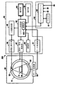
- 1 is a block diagram showing a medical image diagnostic apparatus according to an embodiment.
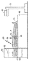
- Explanatory drawing which shows arrangement
- Explanatory drawing which shows the example of a display of the medical image displayed on a display part in one Embodiment.
- the lineblock diagram showing the outline of the position information acquisition part in one embodiment.
- the block diagram which shows the 1st modification of the position information acquisition part in one Embodiment.
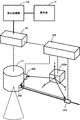
- the block diagram which shows the medical image diagnostic apparatus which concerns on 2nd Embodiment.
- Explanatory drawing which shows arrangement
- the lineblock diagram showing the outline of the position information acquisition part in a 2nd embodiment.
- the block diagram of the configuration of the guide information creation means The figure which shows an example of the guide information displayed superimposed on the echo image.
- the flowchart which shows a series of flows when calculating needle length.
- the flowchart which shows a series of flows after needle length is calculated until needle tip guide information is displayed.
- the figure which shows the correspondence of the inclination-angle of a puncture needle, and a 3rd position.
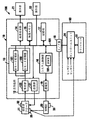
- FIG. 1 is a block diagram illustrating a configuration of an ultrasonic diagnostic apparatus 100 that is a medical image diagnostic apparatus according to an embodiment.
- a main body 10 of an ultrasonic diagnostic apparatus 100 includes an ultrasonic probe 11 that transmits / receives ultrasonic waves to / from a subject (not shown), and drives the ultrasonic probe 11 to the subject.
- a transmission / reception unit 12 that performs ultrasonic scanning and a data processing unit 13 that processes reception signals obtained by the transmission / reception unit 12 to generate image data such as B-mode image data and Doppler image data are provided.
- the ultrasound probe 11, the transmission / reception unit 12, and the data processing unit 13 constitute an imaging unit that captures a subject and acquires a medical image.
- the main body 10 is provided with an image generation unit 14 that generates two-dimensional image data based on the image data output from the data processing unit 13 and an image memory 15 that stores the image data generated by the image generation unit 14. ing. Further, the main body 10 includes a system control unit 16 that controls the entire apparatus, a storage unit 17, an interface unit (I / F unit) 18, and an energization unit 19 that energizes the puncture needle 20.
- a system control unit 16 that controls the entire apparatus, a storage unit 17, an interface unit (I / F unit) 18, and an energization unit 19 that energizes the puncture needle 20.
- a display unit 21 that displays an image generated by the image generation unit 14 and an operation unit 22 that inputs various command signals and the like are connected to the main body 10, and a position information acquisition unit 30 is connected to the interface unit 18. (Details will be described later) are connected.
- the system control unit 16 and each circuit unit are connected via a bus line 101.
- the ultrasonic probe 11 performs ultrasonic wave transmission / reception by bringing its tip surface into contact with the body surface of the subject, and has, for example, a plurality of piezoelectric vibrators arranged one-dimensionally.
- the piezoelectric vibrator is an electroacoustic transducer, which converts an ultrasonic drive signal into a transmission ultrasonic wave during transmission, and converts a reception ultrasonic wave from the subject into an ultrasonic reception signal during reception.
- the ultrasonic probe 11 is, for example, an ultrasonic probe such as a sector type, a linear type, or a convex type. In the following description, the ultrasonic probe 11 may be simply referred to as a probe.
- the transmission / reception unit 12 includes a transmission unit 121 that generates an ultrasonic drive signal and a reception unit 122 that processes an ultrasonic reception signal obtained from the ultrasonic probe 11.
- the transmission unit 121 generates an ultrasonic drive signal and outputs it to the ultrasonic probe 11, and the reception unit 122 outputs an ultrasonic reception signal (echo signal) from the piezoelectric vibrator to the data processing unit 13.
- the data processing unit 13 includes a B mode processing unit 131 that generates B mode image data from a signal output from the transmission / reception unit 12, a Doppler mode (D mode) processing unit 132 that generates Doppler image data, and the like. .
- the B mode processing unit 131 performs envelope detection on the signal from the transmission / reception unit 12 and then performs logarithmic conversion, converts the logarithmically converted signal into a digital signal, generates B mode image data, and generates the image generation unit 14. Output to.
- the D-mode processing unit 132 detects the Doppler shift frequency for the signal from the transmission / reception unit 12 and converts it to a digital signal, and then extracts blood flow, tissue, and contrast agent echo components due to the Doppler effect, and generates Doppler data. And output to the image generation unit 14.
- the image generation unit 14 generates an ultrasonic image using the B-mode image data, Doppler image data, etc. output from the data processing unit 13.
- the image generation unit 14 includes a DSC (Digital Scan Converter), performs scan conversion of the generated image data, and generates an ultrasonic image (B-mode image or Doppler image) that can be displayed on the display unit 21.
- DSC Digital Scan Converter
- the image memory 15 stores the image data generated by the image generation unit 14.
- the image data read from the image memory 15 is output to the monitor 21.
- the image memory 15 stores three-dimensional image (for example, MPR image) data of other modalities.
- the system control unit 16 controls the entire ultrasonic diagnostic apparatus 100 and executes various processes. For example, the processing of the transmission / reception unit 12, the data processing unit 13, and the image generation unit 14 is controlled based on various setting requests input from the operation unit 22 and various control programs and various setting information read from the storage unit 17. In addition, control is performed so that the ultrasonic image stored in the image memory 15 is displayed on the display unit 21.
- the storage unit 17 stores various data such as a control program for performing ultrasonic transmission / reception, image processing, and display processing, diagnostic information (for example, subject ID, doctor's findings, etc.), and a diagnostic protocol. Furthermore, the storage unit 17 is also used for storing images stored in the image memory 15 as necessary. The storage unit 17 stores various information used for processing by the system control unit 16.
- the energization unit 19 supplies an electric current to the puncture needle 20 or supplies a radio wave.
- the display unit 21 displays a GUI (Graphical User Interface) for the operator of the ultrasonic diagnostic apparatus 100 to input various setting requests by operating the operation unit 22, or an ultrasonic image or puncture generated in the main body 10. Display the navigation image of.
- the operation unit 22 includes input devices such as various switches, a keyboard, a trackball, a mouse, and a touch command screen, receives various setting requests from the operator, and transfers the various setting requests to the main body 10.
- the position information acquisition unit 30 acquires position information indicating where the ultrasonic probe 11 and the puncture needle 20 are located.
- the position information acquisition unit 30 for example, a magnetic sensor, an infrared sensor, an optical sensor, a camera, or the like is used. In the following description, an example using a magnetic sensor will be described.
- the position information acquisition unit 30 is a sensor using a magnetic field.
- the transmitter 31 is a magnetic field generation source, a plurality of position sensors 32 and 33 that receive a reference signal from the transmitter 31, and a control unit that controls the transmitter 31. 34 and a system control unit 16 that gives an instruction to the control unit 34.
- the position sensors 32 and 33 may be simply referred to as sensors.
- the position sensors 32 and 33 are attached to the ultrasonic probe 11 and the puncture needle 20, respectively, and the positional relationship and distance information between the probe 11 and the puncture needle 20 are acquired from the position information of the two sensors 32 and 33.
- the position information acquisition unit 30 is not limited to the above-described system, but it is desirable that the following requirements are satisfied.
- the position sensors 32 and 33 are 6-axis sensors, the origin of the magnetic field is used as a reference point, the offset distance in the X, Y, and Z axis directions from the reference point, and the X, Y, and Z axes are the magnetic fields. It is preferable to obtain tilt information indicating how much the tilt is from the reference axis. From these distance and inclination information, it is possible to know at which position in the space the sensor is located and in which direction the probe 11 and the puncture needle 20 are directed.
- the position sensor 32 attached to the ultrasonic probe 11 is fixed by using an adapter determined for each probe so that the relative position and orientation of the probe 11 from the reference position are always constant.
- the sensor 33 attached to the puncture needle 20 is attached using an adapter. By using the adapter, the direction and inclination of the sensor 33 with respect to the puncture needle 20 are fixed, and it is possible to know in which direction the needle tip of the puncture needle 20 is seen from the sensor 33.
- the puncture needle 20 is preferably a straight line that does not bend.
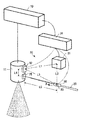
- FIG. 2 is an explanatory diagram schematically showing the arrangement of sensors in the position information acquisition unit 30. That is, the position information acquisition unit 30 includes a transmitter 31 (transmitter), a plurality of position sensors (receivers) 32 and 33, and a control unit 34.
- the transmitter 31 is attached to, for example, a pole 36 at a fixed position near the bed 37 on which the subject P is placed.
- the transmitter 31 transmits a reference signal and forms a magnetic field toward the outside centering on its own device.
- position sensors 32 and 33 made of, for example, magnetic sensors are arranged in an area where the magnetism transmitted from the transmitter 31 can be received.
- the position sensor 32 is attached to the ultrasonic probe 11 that is a support, receives position signals from the transmitter 31, acquires position information in a three-dimensional space, and determines the position and posture (tilt) of the probe 11. To detect.
- the position sensor 33 is attached to an arbitrary position of the puncture needle 20 and acquires position information in a three-dimensional space by receiving a reference signal from the transmitter 31.
- a conductor 35 is attached to the ultrasonic probe 11 (support).
- the conductor 35 is attached in a position set in advance from the sensor 33 and at a predetermined distance from the sensor 33.
- the control unit 34 controls the transmitter 31 to transmit magnetism.
- the control unit 34 acquires position information from the sensors 32 and 33 with reference to the position of the transmitter 31 and supplies the position information to the system control unit 16.
- the conductor 35 can contact the tip of the puncture needle 20, for example, and when the tip of the puncture needle 20 is brought into contact with the conductor 35, a weak current flows from the energization unit 19 to the puncture needle 20.
- the control unit 34 detects that a current has flowed through the conductor 35 and automatically determines that the tip of the puncture needle 20 is at the position of the conductor 35. That is, the conductor 35 is a sensitive element that reacts when the tip of the puncture needle 20 approaches within a preset distance.
- the control unit 34 is connected to the system control unit 16 via the interface unit 18, and the system control unit 16 includes a calculation unit 161. Based on the information from the position sensors 32 and 33 and the conductor 35, the calculation unit 161 is a distance between two points between the sensor 33 of the puncture needle 20 and the needle tip, that is, from the sensor 33 of the puncture needle 20 to the needle tip. Calculate the needle length.
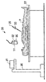
- FIG. 3 is an explanatory diagram showing a display example of a medical image displayed on the display unit 21 when performing cauterization treatment with the puncture needle 20.
- the medical image includes an ultrasound image and a puncture navigation image.
- ablation treatment first, an ultrasonic diagnosis is performed to confirm the location of the tumor (puncture site). That is, the target portion of the subject P is scanned by the ultrasonic probe 11, and tomographic image data that is a two-dimensional image is sequentially acquired and stored in the image memory 15.
- tomographic image data that is a two-dimensional image is sequentially acquired and stored in the image memory 15.
- FIG. 3 a two-dimensional tomographic image Q1 photographed by the ultrasonic probe 11 is displayed, and a tumor location (puncture site) is indicated by a black image Q2.
- the operator specifies the puncture site Q2 on the tomographic image Q1, and the system control unit 16 calculates the puncture port for puncturing the puncture needle 20, the puncture direction, and the distance from the puncture port to the puncture site.
- the operator selects the puncture needle 20 and attaches the sensor 33 to an arbitrary position of the puncture needle 20 (a position corresponding to the needle length L0).
- the conductor 35 is energized by applying the puncture needle 20 to the conductor 35.
- the calculation unit 161 automatically calculates the distance L0 between the two points of the sensor 33 of the puncture needle 20 and the needle tip, that is, the needle length L0 from the sensor 33 of the puncture needle 20 to the needle tip.
- the system control unit 16 displays a mark M indicating the tip of the puncture needle at a position corresponding to the distance L0 when viewed from the puncture port in the puncture direction.
- the system control unit 16 can display the puncture navigation image.
- the guide image Q3 extending from the sensor 33 to the needle tip is displayed, and the mark M is displayed at the needle tip position.
- the operator inserts the puncture needle 20 toward the puncture site Q2 while viewing the guide image Q3 in FIG.
- the image of the puncture needle 20 is displayed in the tomographic image Q1, and it is confirmed that the needle tip of the puncture needle 20 has reached the mark M (puncture site Q2).
- the ablation treatment is performed by, for example, irradiating the tumor portion from the tip of the puncture needle 20 with a radio wave.
- a radio wave is supplied from the energization unit 19 to the puncture needle 20.
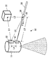
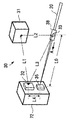
- FIG. 4 is a configuration diagram showing an outline of the position information acquisition unit 30, and also serves as an operation explanatory diagram for calculating the needle length L0 from the sensor 33 of the puncture needle 20 to the needle tip.
- the ultrasonic diagnostic apparatus main body 10 the position information acquisition unit 30, the ultrasonic probe 11, and the puncture needle 20 are shown in an enlarged manner.
- the position information acquisition unit 30 includes a position sensor 32 and a conductor 35 attached to the ultrasonic probe 11, and a position sensor 33 attached to the puncture needle 20.
- An adapter 38 is attached to the puncture needle 20, and the sensor 33 is fixed to the adapter 38.
- the adapter 38 is attached to the puncture needle 20 so that it can be seen in which direction the needle tip is seen from the sensor 33, and the arrow A direction indicates the needle tip direction in the example of FIG.
- an operator determines the type of the ultrasound probe 11 and the puncture needle 20 according to the target site for examination or treatment, and places the adapter 38 at an arbitrary position of the puncture needle 20. The attachment position of the sensor 33 is determined. Then, the operator turns on the navigation switch provided in the operation unit 22 to enter the navigation mode for guiding the insertion of the puncture needle.
- a weak current is passed from the energizing unit 19 to the puncture needle 20 for a certain time.
- the operator brings the tip of the puncture needle 20 into contact with the conductor 35 installed on the probe 11, an electric circuit is formed, and a current flows through the conductor 35 through the puncture needle 20.
- the system control unit 16 recognizes that the needle tip of the puncture needle 20 is at the position of the conductor 35, and automatically calculates the needle length L0 described above.
- the control unit 34 acquires position information (information indicating the distance and direction from the transmitter 31) of the sensor 32 and the sensor 33, and sends it to the system control unit 16.
- the calculation unit 161 of the system control unit 16 calculates the distance L1 between the transmitter 31 and the sensor 32, the distance L2 between the transmitter 31 and the sensor 33, and the distance L3 between the sensor 32 and the sensor 33.
- the distance L0 between the position sensor 33 and the conductor 35 (the needle length L0 from the position sensor 33 of the puncture needle 20 to the needle tip). Can also be calculated.
- the calculation unit 161 automatically measures the needle length L0 of the puncture needle 20 only by the operator touching the conductor 35 with the tip of the puncture needle 20.
- the system control unit 16 controls to display the mark M at the position of the tip of the puncture needle in FIG. 3 based on the information of the needle length L0, and can make the display position of the mark M accurate. .
- the operator can save time and labor for manually inputting information on the needle length L0, and the operation during the inspection can be simplified, so that the load on the operator can be reduced. Since the needle length L0 changes according to the depth of the affected area, operability can be improved by automatically measuring the information of the needle length L0.
- FIG. 5 is a configuration diagram showing an outline of the position information acquisition unit 30 in the first modified example, and shows an example in which a pressure-sensitive sensor 41 is attached to the ultrasonic probe 11 instead of the conductor 35.
- a position sensor 32 and a pressure sensor 41 are attached to the probe 11, and a distance L4 between the position sensor 32 and the pressure sensor 41 is designated in advance.
- the pressure sensitive sensor 41 constitutes a sensitive element that reacts when the tip of the puncture needle 20 approaches (contacts) within a preset distance.
- the control unit 34 acquires the position information (information indicating the distance and direction from the transmitter 31) of the sensor 32 and the sensor 33 and sends it to the system control unit 16. Accordingly, the calculation unit 161 of the system control unit 16 calculates the distances L1 and L2 between the transmitter 31 and the sensors 32 and 33 and the distance L3 between the sensors 32 and 33.
- the control unit 34 recognizes that the tip of the puncture needle 20 is at the position of the pressure sensor 41 in response to the reaction of the pressure sensor 41. Since the distance L4 between the position sensor 32 and the pressure sensor 41 is a preset distance, in response to the pressure sensor 41 recognizing the needle tip, the calculation unit 161 automatically senses with the sensor 33. A distance L0 between the pressure sensors 41 (needle length L0 from the sensor 33 of the puncture needle 20 to the needle tip) is calculated.
- FIG. 6 is a configuration diagram showing an outline of the position information acquisition unit 30 in the second modification, and shows an example in which the proximity sensor 42 is attached to the ultrasonic probe 11 instead of the conductor 35.
- a position sensor 32 and a proximity sensor 42 are attached to the probe 11, and a distance L4 between the sensor 32 and the proximity sensor 42 is designated in advance.
- the proximity sensor 42 constitutes a sensitive element that reacts when the tip of the puncture needle 20 approaches within a preset distance.
- the control unit 34 acquires the position information (information indicating the distance and direction from the transmitter 31) of the sensor 32 and the sensor 33 and sends it to the system control unit 16.
- the calculation unit 161 calculates the distances L1 and L2 between the transmitter 31 and the sensors 32 and 33 and the distance L3 between the sensors 32 and 33.
- the proximity sensor 42 reacts.
- the control unit 34 receives the reaction of the proximity sensor 42 and recognizes that the needle tip has approached the proximity sensor 42. Since the distance L4 between the sensor 32 and the proximity sensor 42 is a preset distance, in response to the proximity sensor 42 recognizing the needle tip, the calculation unit 161 automatically selects between the sensor 33 and the proximity sensor 42. The distance L0 ′ between the two points is calculated. Since the tip of the puncture needle 20 is not actually in contact with the proximity sensor 42, the needle length L0 from the sensor 33 of the puncture needle 20 to the needle tip is calculated by subtracting the proximity distance L5 from the calculated distance L0 ′. can do.
- a three-dimensional camera may be attached in place of the proximity sensor 42.
- a position sensor 32 and a three-dimensional camera are attached to the probe 11, and the distance between the position sensor 32 and the three-dimensional camera is designated in advance.
- the 3D camera recognizes the image of the tip of the puncture needle 20 and the control unit 34 transmits the image recognition result of the 3D camera to the system control unit 16. .
- the calculation unit 161 of the system control unit 16 recognizes that the needle tip has come within the approach distance to the three-dimensional camera, and automatically the needle length from the sensor 33 of the puncture needle 20 to the needle tip in the same manner as in FIG. Is calculated.
- puncture, RFA treatment, or the like can be performed under the guidance of the navigation image. Further, it is not necessary for the operator to manually input the needle length information, and the setting can be performed easily and quickly.
- the medical image diagnostic apparatus according to the second embodiment relates to an X-ray CT apparatus.
- FIG. 7 is a configuration diagram showing an X-ray CT apparatus according to the second embodiment.
- the X-ray CT apparatus 200 includes a gantry 50 and a computer system 60.
- the gantry 50 collects projection data related to the subject P, and includes a rotating frame 51, an X-ray tube 52, an X-ray detector 53, and a data collection unit 54.
- the rotating frame 51 is a ring that is driven to rotate, and is equipped with an X-ray tube 52 and an X-ray detector 53.
- the central portion of the rotating frame 51 is open, and the subject P placed on the top plate 55 of the bed 56 (FIG. 8) is inserted into the opening.
- the X-ray tube 52 is supplied with electric power (tube current, tube voltage) necessary for X-ray exposure from a high voltage generator 66 (described later) via a slip ring. X-rays are exposed to the subject P placed inside.
- the X-ray detector 53 detects X-rays transmitted through the subject P, and is attached to the rotating frame 51 so as to face the X-ray tube 52.
- the X-ray detector 53 is, for example, a multi-slice type detector, and a plurality of X-ray detection elements are two-dimensionally arranged in multiple rows in the channel direction and the slice direction.
- the gantry 50 including the X-ray tube 52 and the X-ray detector 53, the top board 55, and the bed 56 constitute an imaging unit that images a subject and acquires a medical image.
- the rotation of the rotating frame 51 causes the X-ray tube 52 and the X-ray detector 53 to face each other while rotating about the body axis of the subject P.
- the top plate 55 is controlled to move along the body axis direction of the subject P simultaneously with the rotation of the rotating frame 51, so-called helical scanning that scans the subject in a spiral manner is possible.
- the data collection unit 54 is called DAS (Data Acquisition System), converts a signal output from the X-ray detector 53 for each channel into a voltage signal, amplifies it, and converts it into a digital signal. This digital data is sent to the computer system 60.
- DAS Data Acquisition System
- the computer system 60 includes a data processing unit 61, a system control unit 62, an operation unit 63, a display unit 64, an X-ray control unit 65, a high voltage generation unit 66, a gantry / bed control unit 67, and an energization unit 68.
- the data processing unit 61 includes a preprocessing unit, a reconstruction processing unit, a storage unit, and the like, receives raw data (projection data) from the data collection unit 54, performs preprocessing, and then performs reconstruction processing and the like.
- the data processing unit 61 is equipped with, for example, a plurality of types of reconstruction methods, and reconstructs image data by the reconstruction method selected by the operator.
- the reconstructed image data is subjected to image processing for display such as window conversion and RGB processing.
- the data processing unit 61 generates a tomographic image of an arbitrary cross section, a projection image from an arbitrary direction, a three-dimensional image, and the like based on an instruction from the operator.
- Reconstructed image data such as tomographic image data is stored in a storage unit in the data processing unit 61.
- the system control unit 62 performs overall control of the X-ray CT apparatus 200, and performs scan processing, signal processing, image display processing, and the like. Also, a navigation image for puncturing is generated.
- the system control unit 62 includes a calculation unit 621.
- the operation unit 63 includes a keyboard, various switches, a mouse, and the like, and an operator selects a slice to be observed and inputs various scanning conditions such as a slice thickness and the number of slices.
- the display unit 64 displays medical images processed by the data processing unit 61, navigation images for puncture, and the like under the control of the system control unit 62.
- the X-ray control unit 65 controls the high voltage generation unit 66, and the high voltage generation unit 66 supplies power necessary for X-ray exposure to the X-ray tube 52 through the slip ring.
- the gantry / bed control unit 67 rotationally drives the rotary frame 51 and controls the movement of the bed 56 (FIG. 8) and the top plate 55.
- the energization unit 68 supplies a current or supplies a radio wave to the puncture needle 20.
- the position information acquisition unit 30 is connected to the system control unit 62.
- the position information acquisition unit 30 includes a transmitter 31 (transmitter), a plurality of position sensors (receivers) 32 and 33, and a control unit 34 as in the case of FIG.
- the control unit 34 detects that a current has flowed through the conductor 35 and automatically determines that the needle tip of the puncture needle 20 is at the position of the conductor 35.
- FIG. 8 is an explanatory diagram showing the arrangement of the position information acquisition unit 30 in the second embodiment, and shows the arrangement of the transmitter 31, the position sensors 32 and 33, and the conductor 35.
- the transmitter 31 is attached to, for example, a pole 71 at a fixed position near the bed 56 on which the subject P is placed.
- position sensors 32 and 33 made of magnetic sensors are arranged in an area where the magnetism transmitted from the transmitter 31 can be received.
- the position sensors 32 and 33 may be simply referred to as sensors.
- the sensor 32 is attached to a support 72 fixed to the bed 56, for example, and the sensor 33 is attached to an arbitrary position of the puncture needle 20.
- the conductor 35 is attached to the support 72 and attached to a position at a predetermined distance from the sensor 32.
- the control unit 34 controls the transmitter 31 to transmit magnetism.
- the control unit 34 acquires position information from the position sensors 32 and 33 with reference to the position of the transmitter 31 and supplies the position information to the system control unit 62.
- the conductor 35 can contact the tip of the puncture needle 20.
- a weak current is passed from the energization unit 68 to the puncture needle 20.
- the control unit 34 detects that a current has flowed through the conductor 35 and automatically determines that the tip of the puncture needle 20 is at the position of the conductor 35.
- the calculation unit 621 of the system control unit 62 calculates the needle length from the sensor 33 of the puncture needle 20 to the needle tip based on the information from the position sensors 32 and 33 and the conductor 35.
- FIG. 9 is a configuration diagram illustrating an outline of the position information acquisition unit 30, and also serves as an operation explanatory diagram for calculating the needle length L0.
- An adapter 38 is attached to the puncture needle 20, and a sensor 33 is fixed to the adapter 38.
- the adapter 38 is attached to the puncture needle 20 so that it can be seen in which direction the needle tip is seen from the sensor 33.
- the arrow A direction indicates the needle tip direction.
- the calculation unit 621 calculates a distance L1 between the transmitter 31 and the sensor 32, a distance L2 between the transmitter 31 and the sensor 33, and a distance L3 between the sensor 32 and the sensor 33. Since the distance L4 between the position sensor 32 and the conductor 35 is a preset distance, the distance L0 between the sensor 33 and the conductor 35 (the needle length L0 from the sensor 33 of the puncture needle 20 to the needle tip) is also calculated. it can.
- the calculation unit 621 can automatically measure the needle length L0 from the sensor 33 of the puncture needle 20 to the needle tip only by the operator touching the conductor 35 with the tip of the puncture needle 20.
- the operator operates the operation unit 63, sees through the subject P, observes the fluoroscopic image, and determines the treatment target site.
- the operator performs imaging of the treatment target region, acquires volume data, reconstructs a volume image of the subject, and displays it on the display unit 64.
- the operator designates a target (treatment target site) in the volume image and designates the puncture position of the puncture needle 20.
- the system control unit 62 calculates the puncture port for puncturing the puncture needle 20, the puncture direction, and the distance from the puncture port to the puncture site.
- the operator selects the puncture needle 20 and attaches the sensor 33 to an arbitrary position of the puncture needle 20 (a position corresponding to the needle length L0).
- the calculation unit 621 automatically calculates the needle length L0 from the sensor 33 of the puncture needle 20 to the needle tip, and punctures from the puncture port.
- a mark indicating the tip of the puncture needle is displayed at a position corresponding to the distance L0 when viewed in the direction.
- the system control unit 62 displays the navigation image of puncture.
- the guide image extending from the sensor 33 to the needle tip is displayed, and a mark is displayed at the needle tip position.
- the operator inserts the puncture needle 20 toward the puncture site (mark) while viewing the guide image, and performs ablation treatment by irradiating the tumor portion from the tip of the puncture needle 20 with, for example, radio waves.
- a radio wave is supplied from the energization unit 68 to the puncture needle 20.
- the system control unit 62 controls to display a mark indicating the tip of the puncture needle based on the information of the needle length L0, so that the mark display position is accurate. be able to.
- the operator can save time and effort to manually input information on the needle length L0, the operation during the inspection can be simplified, and the load on the operator can be reduced.
- the pressure sensor 41, the proximity sensor 42, or the camera described in the modification of the first embodiment can be used in place of the conductor 35.
- the X-ray CT apparatus has been described.
- measuring and navigating the needle length between the needle tip of the puncture needle 20 and the position sensor 33 can be performed by using an MRI apparatus or an angio apparatus.
- the present invention can be applied to an X-ray imaging apparatus or other medical image diagnostic apparatus.
- the example in which the puncture needle 20 is inserted into the subject and the affected part is cauterized has been described.
- the present invention can also be applied to the case where the tissue collecting puncture needle is inserted into the subject and the affected tissue is collected. .
- the sensor 33 is attached to the puncture needle 20, but the place where the sensor 33 is attached is not limited to the puncture needle 20, and may be any place having a predetermined relative position with respect to the puncture needle 20, for example.
- a place such as a holder (not shown) or the main body 10 of the ultrasonic diagnostic apparatus 100 may be used.
- the needle length information acquisition unit obtains the position information of the puncture needle 20 by referring to the relative position based on the position information of the sensor 33 when the tip of the puncture needle is brought into contact with the reference position member. Further, referring to the position information of the reference position member, information on the needle length of the puncture needle is obtained.
- the conductor 35, the pressure sensor 41, the proximity sensor 42, and the camera are used to detect that the tip of the puncture needle 20 is aligned with a predetermined position.
- a method for acquiring the needle length by instructing the measurement by operating the input unit (not shown) when the tip of the puncture needle is adjusted to a predetermined position without using the conductor 35 or the like will be described below. explain.
- the structure of the medical image diagnostic apparatus according to the embodiment includes (1) a magnetic sensor, for example, at a first position of the puncture needle.
- a predetermined position is provided in the imaging unit (meaning means other than the puncture needle in the medical image diagnostic apparatus).
- the tip (needle tip) of the puncture needle is adjusted to a predetermined position.
- the first position and the predetermined position are measured by the position measurement system.
- a needle length that is a distance from the first position to the predetermined position is obtained.
- measuring a predetermined position by the position measurement system means directly measuring the predetermined position by the position measurement system (this is referred to as “direct measurement”) and other than the predetermined position. This includes measuring a position and obtaining a predetermined position from the measured value (this is referred to as “indirect measurement”).
- a magnetic sensor is provided at the predetermined position, and the predetermined position may be measured by the position measurement system.
- the needle length may not be accurately measured if the position where the needle tip is aligned deviates from the predetermined position. Therefore, a position having a predetermined positional relationship with the position where the magnetic sensor is provided (referred to as “third position” described later) is provided, and the needle length is accurately measured by aligning the needle tip with that position. To do.
- the position at which the magnetic sensor is provided on the puncture needle is “first position”
- the position at which the magnetic sensor is provided on the imaging unit is “second position”
- a predetermined positional relationship with the second position is established.
- the position having this will be described as a “third position”.
- the “first position” refers to a position where a first measurement target (a magnetic sensor 310 described later) is provided.
- the “second position” refers to a position where a second measurement target (a magnetic sensor 320 described later) is provided.
- FIG. 10 is a configuration block diagram of a medical image diagnostic apparatus according to the third embodiment.
- an ultrasonic diagnostic apparatus will be described as a medical image diagnostic apparatus.
- FIG. 10 is a configuration block diagram of the ultrasonic diagnostic apparatus.
- the ultrasonic diagnostic apparatus includes an ultrasonic probe 11, a position measurement system 300 (see FIG. 11), a needle length information acquisition unit 100A (see FIG. 11), a display processing unit 118, and a display unit 21.
- the ultrasonic probe 11 is an example of an “imaging unit”.
- the position measurement system 300 is an example of a “position information acquisition unit”.
- the position measurement system 300 includes a magnetic field source (transmitter) 300a, magnetic sensors 310 and 320 that receive a change in the magnetic field, and a control unit 340 that controls them. Note that the measurement by the position measurement system 300 is performed when the user instructs the measurement manually by causing the needle tip (tip of the puncture needle) to contact the third position and operating the input unit (not shown). Executed. The needle length is obtained based on the measured result.
- the magnetic field generation source 300a is provided around the ultrasonic diagnostic apparatus.
- the position where the magnetic field generation source 300a is provided is the origin position of the XYZ coordinates.
- the magnetic field generation source 300a has three-direction orthogonal coils.
- the magnetic sensors 310 and 320 have three-direction orthogonal coils. When the three coils of the magnetic field generation source 300a are sequentially excited, an electromotive force is sequentially generated in the three coils of the magnetic force sensors 310 and 320.
- Magnetic sensor 310 is provided at the first position of the puncture needle via an adapter (not shown).
- the XYZ coordinates (x 1 , y 1 , z 1 ) of the first position, and the puncture needle The tilt angles ( ⁇ , ⁇ , ⁇ ) are measured.
- ⁇ , ⁇ , and ⁇ are inclination angles of the puncture needle with respect to the X axis, the Y axis, and the Z axis.
- the magnetic sensor 320 is provided at the second position of the ultrasonic probe 11. Based on the signal (the above-described electromotive force) from the magnetic sensor 320 that has received a change in the magnetic field from the magnetic field generation source 300a, the XYZ coordinates (x 2 , y 2 , z 2 ) of the second position, and the ultrasonic probe 11 tilt angles ( ⁇ , ⁇ , ⁇ ) are measured.
- the coordinates of the ultrasonic probe 11 with the second position as the origin are set as UVW coordinates.
- the inclination angle of the ultrasonic probe 11 refers to the inclination of the UVW coordinates with respect to the XYZ coordinates.
- the UVW coordinates are rotated by ⁇ , ⁇ , and ⁇ around the U axis, the V axis, and the W axis, respectively.
- An example of “the tilt angle of the imaging unit” is “the tilt angle of the ultrasonic probe 11”.
- the position measurement system 300 measures the first position and the tilt angle of the puncture needle, and the second position and the tilt angle of the ultrasonic probe 11.
- the ultrasonic probe 11 is provided with a third position having a predetermined positional relationship with the second position.
- the positional relationship is stored in the storage unit 116 (described later).
- FIG. 11 is a configuration block diagram of the guide information creating means.
- the needle length information acquisition unit 100A includes a first calculation unit 111, a second calculation unit 112, a third calculation unit 113, a creation unit 115, and a storage unit 116.
- the needle length information acquisition unit 100A instructs the position measurement system 300 to perform measurement, and from the position measurement system 300, the measurement values (XYZ coordinates of the first position, tilt angle of the puncture needle, XYZ coordinates of the second position, The inclination angle of the acoustic probe 11 is acquired.
- the storage unit 116 stores the positional relationship of the third position with respect to the second position.
- the positional relationship is the inclination angle ( ⁇ , ⁇ , ⁇ ) of the straight line connecting the second position and the third position, and the length R 1 of the straight line.
- ⁇ , ⁇ , and ⁇ are inclination angles of straight lines with respect to the U axis, the V axis, and the W axis in the UVW coordinate system.
- the first calculation unit 111 includes the XYZ coordinates (x 2 , y 2 , z 2 ) of the second position where the magnetic force sensor 320 is provided, and the slope of the straight line connecting the second position and the third position.
- the angle ( ⁇ , ⁇ , ⁇ ) and the length R 1 of this straight line are obtained.
- ⁇ , ⁇ , and ⁇ are rotation angles (inclination angles of the photographing unit) when the UVW coordinates are rotated about the U axis, the V axis, and the W axis, respectively, so that the UVW coordinates match the XYZ coordinates. .
- the second calculating means 112 is configured to calculate the three-dimensional coordinates (x 3 , y 3 , z 3 ) of the determined third position and the three-dimensional coordinates (x 1 , y 1 , By substituting into the following formula (2) by z 1 ), the needle length L, which is the distance from the tip of the puncture needle to the second measurement object, is obtained.
- the measurement by the position measurement system 300 is executed when the needle tip is brought into contact with the third position.
- the needle length L is obtained based on the measured result.
- the third calculation means 113 includes the XYZ coordinates (x 11 , y 11 , z 11 ) of the first position, the tilt angles ⁇ , ⁇ , ⁇ of the puncture needle with respect to the X axis, the Y axis, and the Z axis, and the needle length
- the position (x 4 , y 4 , z 4 ) of the needle tip is obtained by substituting L into the following equation (3).
- the needle length information acquisition unit 100A includes a creation unit 115.
- the creation unit 115 has software for drawing, starts this software, and calculates the XYZ coordinates of the first position, the tilt angle of the puncture needle, the needle length, and the function represented by the above-described equation (3). Using the obtained needle tip position as a parameter, guide information for guiding the needle tip including an image of the needle tip position and an image of the ablation target range is created.
- parameters used when creating guide information will be described.
- the parameters are stored in advance in the storage unit 116 in association with the type of puncture needle.
- the parameter indicates the specifications of the puncture needle, and includes ablation target range, needle guide color depth, and needle guideline display / non-display.
- the type of puncture needle may be simply referred to as “needle type”.
- the needle type is a concept having the form type of the puncture needle, the type of function of the puncture needle, and the type of examination (including the examination purpose and examination site) in which the puncture needle is used.
- the needle type for example, a monopolar type in which one electrode is provided at the position of the tip of the puncture needle, and two electrodes are provided with an insulating portion between the tip of the puncture needle at a predetermined length.
- a bipolar type is a bipolar type.
- the shochu target range includes the shape, size, and center position of the shochu target range.
- the “shape”, “size”, and “center position” of the ablation target range differ depending on the type (needle type) of the puncture needle.
- the monopolar type is a circle
- the bipolar type is an ellipse.
- the monopolar type is the radius in a circle
- the bipolar type is the length of a major axis and a minor axis in an ellipse.
- the “center position” is the position of the tip of the puncture needle (position where the electrode is provided) in the monopolar type.
- the position of the tip of the puncture needle is obtained by the third calculation means 113 as described above.
- the “center position” is a position (a position where an insulating portion is provided) that is a predetermined distance away from the tip of the puncture needle in the bipolar type.
- the position away from the tip of the puncture needle by a predetermined length is also obtained by the fourth calculation means (not shown).
- the “shape”, “size”, and “center position” of the ablation target range will be described on the assumption that the type (needle type) of the puncture needle is a monopolar type. That is, the “shape” is a circle, and the “center position” is the position of the tip of the puncture needle.
- the color density of the needle guideline is used to display a thin color when the image displayed under the guideline is difficult to see.
- Display / hide needle guideline is used to display / hide the guideline depending on whether the image displayed under the guideline is easy to see.
- the creation unit 115 receives the position of the tip of the puncture needle obtained by the third calculation unit 113 and the “shape” and “size” of the ablation target range as parameters stored in the storage unit 116 in advance. A circle with a predetermined radius centered on the position (cautery target range) is created as guide information.
- the creation unit 115 is based on the position of the tip of the puncture needle obtained by the third calculation means 113 and the first position of the puncture needle measured by the position measurement system (position where the magnetic force sensor 310 is provided).
- the needle guidelines are created as guide information.
- the display processing unit 118 includes “color density of needle guidelines”, “display / non-display of needle guidelines” as parameters stored in advance in the storage unit 116, and guide information created by the creation unit 115 (here Then, in response to the needle guideline), the needle guideline NL is displayed / hidden on the display unit 21 so as to be superimposed on the echo image EG acquired by the imaging unit. Thereby, the puncture needle can be accurately and easily inserted into the target site.
- the position measurement system 300 measures the XYZ coordinates (x 11 , y 11 , z 11 ) of the first position and the tilt angles ( ⁇ , ⁇ , ⁇ ) of the puncture needle.
- the drawing software of the creation unit 115 is continuously executed, and the XYZ coordinates (x 11 , y 11 , z 11 ) of the first position, the tilt angles ( ⁇ , ⁇ , ⁇ ) of the puncture needle, the needle
- An image of the needle tip position and an image of the ablation target range are created using the length L and the needle tip position obtained by using the function represented by the expression (3).
- the echo image EG is acquired by the imaging unit.
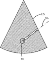
- FIG. 12 is a diagram showing guide information displayed so as to be superimposed on the echo image EG.
- an image of the needle type depicted in the echo image EG is indicated by a white portion, and a needle guideline NL displayed by being superimposed on the echo image EG is indicated by a one-dot chain line.
- the display processing unit 118 matches the coordinates of the ablation target range created by the creation unit 115 with the coordinates when the echo image EG is displayed, and displays the ablation target range overlaid on the echo image EG. This is displayed on the unit 21. By displaying the ablation target range, it becomes easier to match the ablation target range to the target part.
- FIG. 12 shows the ablation target range TR displayed in an overlapping manner with the echo image EG.
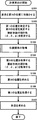
- FIG. 13 is a flowchart showing a series of flows when calculating the needle length.
- the needle tip is brought into contact with the third position (step S101).
- the needle tip is brought into contact with the third position while bringing the ultrasonic probe 11 and the puncture needle close to each other. Since it is good, the contact
- the position measurement system 300 measures the first position, the second position, and the tilt angle of the ultrasonic probe 11 (imaging unit) (step S102).
- the above first position, second position, and measurement of the tilt angle of the ultrasonic probe 11 may be performed in any order. After these are measured, the needle tip may be removed from the third position, and the tilt angle of the ultrasonic probe 11 may be changed.
- the first calculation unit 111 acquires the positional relationship of the third position with respect to the second position from the storage unit 116 (step S103). Next, the first calculation unit 111 acquires the second position and the inclination angle of the ultrasonic probe 11 (step S104).
- the first calculation unit 111 substitutes the positional relationship of the third position with respect to the second position, the second position, and the inclination angle of the ultrasonic probe 11 into the equation (1), and 3 is obtained (step S105).
- the second calculation means 112 acquires the first position (step S106).
- the second calculation means 112 substitutes the second position and the third position into the equation (2) to obtain the needle length (step S107).
- the position measurement system 300 measures the first position, the second position, and the inclination angle of the ultrasonic probe 11, and the measurement result. Based on the above, the needle length was obtained. However, in the main measurement after the preliminary measurement, the needle tip is removed from the third position. In this measurement, the position measurement system 300 measures the first position and the tilt angle of the puncture needle, and the needle tip position is obtained based on the measurement result, and the needle tip guide information is created by the creation unit 115. Needle tip guide information is displayed on the display unit 21.
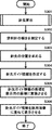
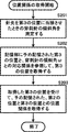
- FIG. 14 is a flowchart showing a series of flows from the calculation of the needle length to the display of the needle tip guide information.
- the needle length is calculated (step S301), and then the position measurement system 300 measures the XYZ coordinates of the first position and the tilt angle of the puncture needle (step S302).
- the third calculation means 113 obtains the position of the needle tip by substituting the needle length, the XYZ coordinates of the first position, and the tilt angle of the puncture needle into the equation (3) (step S303). ).
- the creating unit 115 creates a needle guideline as needle tip guide information based on the obtained needle tip position and the XYZ coordinates of the first position (step S304). At this time, an ablation target range (including its center position, shape, and size) is created as needle tip guide information.
- the display processing unit 118 converts the coordinates of the ablation target range into coordinates when the echo image EG is displayed (step S305).
- the display processing unit 118 causes the display unit 21 to display the ablation target range on the echo image EG (step S306).
- the positional relationship of the third position with respect to the second position is one.
- the third position is one, when the needle length is obtained, it is necessary to always bring the needle tip into contact with the third position. Therefore, depending on the place where the third position is provided, There is a problem that a situation in which contact is difficult occurs. Therefore, if a plurality of third positions are provided, a place where the needle tip is easily brought into contact is selected from the plurality of third positions, and the needle tip is brought into contact therewith, it is difficult to come into contact with the needle tip. It is possible to avoid the situation.
- a plurality of third positions are provided with respect to the second position. Therefore, the positional relationship of the third position with respect to the second position is plural. That is, if the position cannot be specified as any one of the plurality of positional relationships, the first calculation unit 111 cannot obtain the third position based on the positional relationships.
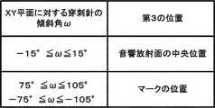
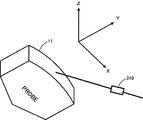
- FIG. 15 is a diagram illustrating a correspondence relationship between the tilt angle of the tilt needle and the third position
- FIG. 16 is a flowchart illustrating a series of flows when the positional relationship between the second position and the third position is acquired.
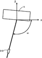
- FIG. 17 is a view showing an example of a puncture needle with the needle tip in contact with the third position
- FIG. 18 is an example of an inclination angle of the puncture needle when the needle tip is brought into contact with the third position.
- FIG. 19 is a diagram illustrating a positional relationship between the second position and the third position.
- the correspondence relationship between the third position and the inclination angle of the puncture needle is stored in advance in the storage unit 116.
- the position measurement system 300 measures the tilt angle of the puncture needle when the needle tip is brought into contact with the third position (step S201).
- the position measurement system 300 measures the tilt angle ⁇ of the puncture needle.
- the first calculation unit 111 refers to the correspondence shown in FIG. A certain third position is acquired (step S202).
- the first calculation unit 111 receives the acquired third position, and acquires the positional relationship between the second position and the third position shown in FIG. 19 (step S203). At this time, the inclination angles of the straight line connecting the second position and the third position are ⁇ 1, ⁇ 1, ⁇ 1, and the length of the straight line is R1.
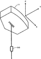
- FIG. 20 is a diagram showing another example of a puncture needle with the needle tip in contact with the third position
- FIG. 21 shows an inclination angle of the puncture needle when the needle tip is brought into contact with the third position. It is a figure which shows another example.
- the position measurement system 300 measures the tilt angle ⁇ of the puncture needle.
- the first calculation unit 111 refers to the correspondence shown in FIG. A third position, which is the position of the mark, is acquired (step S202).
- the first calculation unit 111 receives the acquired third position, and acquires the positional relationship between the second position and the third position shown in FIG. 19 (step S203). At this time, the inclination angles of the straight line connecting the second position and the third position are ⁇ 2, ⁇ 2, ⁇ 2, and the length of the straight line is R2.
- an example of an ultrasonic diagnostic apparatus is shown as a medical image diagnostic apparatus, and an example of an ultrasonic probe 11 is shown as an imaging unit, but this is not a limitation.
- another example of a medical image diagnostic apparatus is an X-ray CT apparatus.
- An example of an imaging unit in an X-ray CT apparatus is a bed apparatus on which a subject is placed. At this time, the second position and the third position are provided in the bed apparatus.
- the position measurement system 300 is shown as an example of a measurement unit that measures the first position provided on the puncture needle and the second position provided on the ultrasonic probe 11, but the first position and Any device can be used as long as it can measure the three-dimensional coordinates of the second position and the inclination angle of the ultrasonic probe 11.
- the needle tip is brought into contact with the third position having a predetermined positional relationship with the second position, it goes without saying that the needle tip may be brought into contact with the second position.
- the third position is equal to the second position.
Landscapes
- Health & Medical Sciences (AREA)
- Life Sciences & Earth Sciences (AREA)
- Engineering & Computer Science (AREA)
- Biomedical Technology (AREA)
- Medical Informatics (AREA)
- Pathology (AREA)
- Radiology & Medical Imaging (AREA)
- Biophysics (AREA)
- Physics & Mathematics (AREA)
- Heart & Thoracic Surgery (AREA)
- Nuclear Medicine, Radiotherapy & Molecular Imaging (AREA)
- Molecular Biology (AREA)
- Surgery (AREA)
- Animal Behavior & Ethology (AREA)
- General Health & Medical Sciences (AREA)
- Public Health (AREA)
- Veterinary Medicine (AREA)
- Computer Vision & Pattern Recognition (AREA)
- Ultra Sonic Daignosis Equipment (AREA)
Abstract
穿刺針の針長を簡便かつ正確に測定することができる超音波診断装置及び医用画像診断装置を提供する。実施形態に係る超音波診断装置は、被検体に対し超音波の送受波を行う超音波プローブと、超音波プローブに備えられた基準位置部材、及び、穿刺針に対し予め定められた相対位置を有する場所に取り付けられたセンサを含み、基準位置部材及びセンサの位置情報を取得する位置情報取得部と、穿刺針の先端部を基準位置部材に当接させたときの基準位置部材及びセンサの位置情報並びに相対位置から穿刺針の針長の情報を取得する針長情報取得部と、針長の情報に基づいて穿刺針による穿刺を支援する情報を表示する表示部と、を備える。
Description
本発明の実施形態は、超音波診断装置及び医用画像診断装置に関する。
従来、医用画像診断装置として超音波診断装置、X線CT装置、MRI装置等が使用されている。また穿刺針を被検体内に穿刺し、穿刺針の先端から腫瘍部にラジオ波等を照射する焼灼治療法がある。焼灼治療は、RFA(Radio Frequency Ablation)と呼ばれている。またRFAに限らず、穿刺針を被検体に挿入して患部の組織を採取することもある。
例えば、超音波診断装置を用いて焼灼治療を行う場合、超音波プローブと穿刺針にそれぞれ位置センサを取付け、位置センサからの情報を用いてプローブと穿刺針の位置を計測し、超音波診断装置によって生成した2次元画像上に穿刺針の位置を表示するようにしている。
これにより、超音波診断装置によって生成した2次元画像を参照しながら穿刺針をナビゲートすることができ、腫瘍等の穿刺対象部位に穿刺することができる。またRFAでは、腫瘍部を焼灼することでガスが発生し、超音波画像が見えにくくなるため、ナビゲーションの画像を参照することで穿刺針の位置を確認することができる。
ところで、従来では穿刺治療の直前に、穿刺針を選択して、選択した穿刺針に位置センサを取り付ける場合があり、かつ穿刺針のどの部分に位置センサを取り付けるかをオペレータが任意に選択する場合がある。どの穿刺針を用いるか、どの位置にセンサを取り付けるかは、患部の位置(深さ)によって変える必要があるため、穿刺を行う直前までセンサの取付位置を決めることができないケースがある。
センサの取付位置が任意の場合、位置センサの情報だけでは、穿刺針のどの位置にセンサが付いているかを判断できないため、穿刺作業の前に穿刺針のどの位置にセンサを取り付けたかをオペレータが装置に入力する必要がある。したがって、検査開始前に事前に位置センサの取付位置を決めることが困難な場合、オペレータは、検査中又は術中にセンサの取付位置の情報を手入力する必要があるため、非常に煩雑でありオペレータの負荷が大きいという不具合がある。
発明が解決しようとする課題は、穿刺針の針長を簡便かつ正確に測定することができる超音波診断装置及び医用画像診断装置を提供することにある。
実施形態に係る超音波診断装置は、被検体に対し超音波の送受波を行う超音波プローブと、超音波プローブに備えられた基準位置部材、及び、穿刺針に対し予め定められた相対位置を有する場所に取り付けられたセンサを含み、基準位置部材及びセンサの位置情報を取得する位置情報取得部と、穿刺針の先端部を基準位置部材に当接させたときの基準位置部材及びセンサの位置情報並びに相対位置から穿刺針の針長の情報を取得する針長情報取得部と、針長の情報に基づいて穿刺針による穿刺を支援する情報を表示する表示部と、を備える。
以下、発明を実施するための形態について、図面を参照して説明する。尚、各図において同一箇所については同一の符号を付す。
(第1の実施形態)
図1は、一実施形態に係る医用画像診断装置である超音波診断装置100の構成を示すブロック図である。図1において、超音波診断装置100の本体10は、被検体(図示せず)に対して超音波の送受波を行なう超音波プローブ11と、超音波プローブ11を駆動して被検体に対して超音波走査を行う送受信部12と、送受信部12によって得られた受信信号を処理してBモード画像データ、ドプラ画像データ等の画像データを生成するデータ処理部13を備えている。超音波プローブ11、送受信部12及びデータ処理部13は、被検体を撮影して医用画像を取得する撮影部を構成する。
図1は、一実施形態に係る医用画像診断装置である超音波診断装置100の構成を示すブロック図である。図1において、超音波診断装置100の本体10は、被検体(図示せず)に対して超音波の送受波を行なう超音波プローブ11と、超音波プローブ11を駆動して被検体に対して超音波走査を行う送受信部12と、送受信部12によって得られた受信信号を処理してBモード画像データ、ドプラ画像データ等の画像データを生成するデータ処理部13を備えている。超音波プローブ11、送受信部12及びデータ処理部13は、被検体を撮影して医用画像を取得する撮影部を構成する。
本体10には、データ処理部13から出力された画像データを基に2次元画像データの生成等を行う画像生成部14と、画像生成部14で生成した画像データを記憶する画像メモリ15を設けている。また本体10には、装置全体を制御するシステム制御部16と、記憶部17と、インターフェース部(I/F部)18と、穿刺針20に通電する通電部19を備えている。
さらに本体10には、画像生成部14で生成された画像等を表示する表示部21と、各種のコマンド信号等を入力する操作部22が接続され、インターフェース部18には、位置情報取得部30(詳細は後述)が接続されている。尚、システム制御部16と各回路部との間は、バスライン101を介して接続されている。
超音波プローブ11は、その先端面を被検体の体表面に接触させて超音波の送受波を行なうものであり、例えば1次元に配列された複数個の圧電振動子を有している。圧電振動子は電気音響変換素子であり、送波時には超音波駆動信号を送信超音波に変換し、また受波時には被検体からの受信超音波を超音波受信信号に変換する。超音波プローブ11は、例えば、セクタ型、リニア型又はコンベックス型などの超音波プローブである。以下の説明では、超音波プローブ11を単にプローブと呼ぶ場合もある。
送受信部12は、超音波駆動信号を生成する送信部121と、超音波プローブ11から得られる超音波受信信号を処理する受信部122とを備えている。送信部121は、超音波駆動信号を生成して超音波プローブ11に出力し、受信部122は、圧電振動子からの超音波受信信号(エコー信号)をデータ処理部13に出力する。
データ処理部13は、送受信部12から出力された信号から、Bモード画像データを生成するBモード処理部131と、ドプラ画像データを生成するドプラモード(Dモード)処理部132等を備えている。Bモード処理部131は、送受信部12からの信号に対して包絡線検波を行ったのち対数変換し、対数変換した信号をデジタル信号に変換してBモード画像データを生成し、画像生成部14に出力する。
Dモード処理部132は、送受信部12からの信号に対してドプラ偏移周波数を検出しデジタル信号に変換した後、ドプラ効果による血流や組織、造影剤エコー成分を抽出し、ドプラデータを生成して画像生成部14に出力する。
画像生成部14は、データ処理部13から出力されたBモード画像データ、ドプラ画像データ等を用いて超音波画像を生成する。また画像生成部14は、DSC(Digital Scan Converter)を含み、生成した画像データの走査変換を行い、表示部21に表示可能な超音波画像(Bモード画像やドプラ画像)を生成する。
画像メモリ15は、画像生成部14によって生成された画像データを記憶する。また画像メモリ15から読み出した画像データは、モニタ21に出力される。また、画像メモリ15は、他のモダリティの3次元画像(例えば、MPR画像など)データを記憶する。
システム制御部16は、超音波診断装置100の全体を制御して各種の処理を実行する。例えば、操作部22から入力された各種設定要求や、記憶部17から読込んだ各種制御プログラムおよび各種設定情報に基づき、送受信部12、データ処理部13及び画像生成部14の処理を制御する。また画像メモリ15に記憶した超音波画像などを表示部21に表示するように制御する。
記憶部17は、超音波送受信、画像処理および表示処理を行なうための制御プログラムや、診断情報(例えば、被検体ID、医師の所見など)や、診断プロトコルなどの各種データを記憶する。さらに記憶部17は、必要に応じて画像メモリ15が記憶する画像の保管などにも使用される。また記憶部17は、システム制御部16による処理に用いられる各種情報を記憶する。通電部19は穿刺針20に電流を流したり、ラジオ波の供給を行う。
表示部21は、超音波診断装置100のオペレータが操作部22を操作して各種設定要求を入力するためのGUI(Graphical User Interface)を表示したり、本体10において生成された超音波画像や穿刺のナビゲーション画像を表示する。操作部22は、各種スイッチ、キーボード、トラックボール、マウス、タッチコマンドスクリーン等の入力デバイスを備え、オペレータからの各種設定要求を受け付け、本体10に対して各種設定要求を転送する。
次に位置情報取得部30について説明する。位置情報取得部30は、例えば、超音波プローブ11及び穿刺針20がどこに位置するかを示す位置情報を取得する。位置情報取得部30としては、例えば、磁気センサや、赤外線センサ、光学センサ、カメラなどが使用される。以下の説明では、磁気センサを用いる例を述べる。
位置情報取得部30は、磁場を利用したセンサであり、磁場の発生源であるトランスミッタ31と、トランスミッタ31からの基準信号を受信する複数の位置センサ32,33と、トランスミッタ31を制御するコントロールユニット34、及びコントロールユニット34に対し指示をおこなうシステム制御部16からなるシステムである。尚、以下の説明では、位置センサ32,33を単にセンサと呼ぶこともある。
このシステムを利用し、超音波プローブ11と穿刺針20に位置センサ32、33をそれぞれ取り付け、2つのセンサ32、33の位置情報からプローブ11と穿刺針20の位置関係と距離情報を取得する。尚、位置情報取得部30は、上述したシステムに限られるものではないが、以下の要件を満たすことが望ましい。
即ち、位置センサ32,33は6軸センサであり、磁場の発生元を基準点とし、基準点からのX,Y,Z軸方向のオフセット距離と、X,Y,Zのそれぞれの軸が磁場の基準軸からどれだけ傾いているかを示す傾きの情報を取得するものがよい。これらの距離と傾きの情報により、空間上のどの位置にセンサがあるのか、またプローブ11や穿刺針20がどの方向に向いているのかを知ることができる。
また超音波プローブ11に取り付ける位置センサ32は、プローブ毎に決められたアダプタを使用して固定され、プローブ11の基準位置からの相対位置および向きは常に一定となるようにしている。同様に穿刺針20に取り付けるセンサ33は、アダプタを用いて取り付けられる。アダプタを用いることで、穿刺針20に対するセンサ33の向きや傾きは固定され、センサ33から見てどの方向に穿刺針20の針先があるかを知ることができる。また、穿刺針20は、直線であり撓むことがないものが望ましい。
図2は、位置情報取得部30におけるセンサの配置を概略的に示す説明図である。即ち、位置情報取得部30は、トランスミッタ31(送信器)と、複数の位置センサ(受信器)32,33と、コントロールユニット34を含む。トランスミッタ31は、例えば、被検体Pが載置された寝台37の近くの固定位置にあるポール36等に取り付けられる。
トランスミッタ31は、基準信号を送信し自装置を中心として外側に向かって磁場を形成する。またトランスミッタ31によって形成される3次元の磁場には、トランスミッタ31から送信される磁気を受信可能な領域内に、例えば磁気センサでなる位置センサ32,33を配置している。
位置センサ32は、支持体である超音波プローブ11に取り付けられ、トランスミッタ31からの基準信号を受信することにより、3次元空間上の位置情報を取得し、ブローブ11の位置と姿勢(傾き)を検出する。また位置センサ33は、穿刺針20の任意の位置に取り付けられ、トランスミッタ31からの基準信号を受信することにより、3次元空間上の位置情報を取得する。
また超音波プローブ11(支持体)には、伝導体35を取り付けている。伝導体35は、センサ33から予め設定した方向で、かつセンサ33から予め設定した距離を置いた位置に取り付けている。コントロールユニット34は、トランスミッタ31を制御して磁気の送信を行う。またコントロールユニット34は、トランスミッタ31の位置を基準にして、センサ32,33からの位置情報を取得し、システム制御部16に供給する。
伝導体35は、例えば穿刺針20の先端が接触可能であり、穿刺針20の先端を伝導体35に接触させたときに、穿刺針20に通電部19から微弱な電流を流す。コントロールユニット34は、伝導体35に電流が流れたことを検出して、穿刺針20の針先が伝導体35の位置にあると自動的に判断する。つまり、伝導体35は、穿刺針20の先端部が予め設定した距離以内に近づいたときに反応する感応素子である。
コントロールユニット34は、インターフェース部18を介してシステム制御部16に接続されており、システム制御部16は演算部161を含む。演算部161は、位置センサ32,33及び伝導体35からの情報をもとに、穿刺針20のセンサ33と針先との二点間距離、つまり穿刺針20のセンサ33から針先までの針長を計算する。
図3は、穿刺針20により焼灼治療を行う際に表示部21に表示される医用画像の表示例を示す説明図である。医用画像は、超音波画像と穿刺のナビゲーション画像を含む。焼灼治療では、先ず、超音波診断を行い腫瘍の場所(穿刺部位)を確認する。即ち、超音波プローブ11によって被検体Pの対象部位を走査し、2次元画像である断層像のデータを順次に取得し、画像メモリ15に格納する。2次元の断層像のデータを順次に画像メモリ15に蓄積することにより、3次元画像を構成することができ、この3次元画像をもとに穿刺部位を特定する。
図3では、超音波プローブ11により撮影された2次元の断層像Q1を表示し、腫瘍の場所(穿刺部位)を黒い画像Q2で示している。オペレータは、断層像Q1上で穿刺部位Q2を特定し、システム制御部16は、穿刺針20を刺す穿刺口及び穿刺方向、穿刺口から穿刺部位までの距離を算出する。
ここでオペレータは、穿刺針20を選択し、穿刺針20の任意の位置(針長L0に相当する位置)にセンサ33を取り付ける。そして穿刺針20を伝導体35に当てることにより伝導体35に通電する。通電により、演算部161は穿刺針20のセンサ33と針先との二点間距離L0、つまり穿刺針20のセンサ33から針先までの針長L0を自動的に計算する。システム制御部16は、穿刺口から穿刺方向に見て距離L0に対応する位置に、穿刺針の先端を示すマークMを表示する。
また位置センサ33からは、穿刺針20の針先がどの方向に向いているかを示す情報を得ることができるため、穿刺針20の穿刺口が決まれば、システム制御部16は、穿刺のナビゲーション画像として、センサ33から針先まで延びるガイド画像Q3を表示し、針先の位置にマークMを表示する。
オペレータは、図3のガイド画像Q3を見ながら穿刺針20を穿刺部位Q2に向けて挿入する。穿刺針20が挿入されるに連れ、断層像Q1には穿刺針20の画像が表示され、穿刺針20の針先がマークM(穿刺部位Q2)に到達したことを確認したら、オペレータの操作により、穿刺針20の先端から腫瘍部に、例えばラジオ波を照射して焼灼治療を行う。ラジオ波は通電部19から穿刺針20に対して供給する。
図4は、位置情報取得部30の概略を示す構成図であり、穿刺針20のセンサ33から針先までの針長L0を算出する動作説明図を兼ねている。図4では、超音波診断装置本体10と、位置情報取得部30と、超音波プローブ11及び穿刺針20を拡大して示している。位置情報取得部30は、コントロールユニット34及びトランスミッタ31のほかに、超音波プローブ11に取り付けた位置センサ32と伝導体35、及び穿刺針20に取り付けた位置センサ33を含む。
穿刺針20にはアダプタ38が取り付けられ、センサ33はアダプタ38に固定されている。またアダプタ38は、センサ33から見てどの方向に針先があるかが分かるように穿刺針20に取り付けられ、図4の例では矢印A方向が針先方向を示している。
図4において、穿刺を実施する場合、オペレータ(医師等)は検査又は治療の対象部位に応じて超音波プローブ11の種類と穿刺針20を決定し、穿刺針20の任意の場所にアダプタ38を取り付け、センサ33の取付位置を決める。そしてオペレータは、操作部22に設けたナビゲーションスイッチをオンにし、穿刺針の挿入をガイドするナビゲーションモードにする。
ナビゲーションスイッチのオンの後、通電部19からは一定時間、穿刺針20に微弱な電流を流す。オペレータが、穿刺針20の先端をプローブ11上に設置した伝導体35に接触させると電気回路が形成され、穿刺針20を介して伝導体35に電流が流れる。伝導体35に電流が流れると、システム制御部16は、穿刺針20の針先が伝導体35の位置にあることを認識し、前述した針長L0を自動的に算出する。
図4に示すように、コントロールユニット34は、センサ32とセンサ33の位置情報(トランスミッタ31からの距離と方向を示す情報)を取得し、システム制御部16に送る。これにより、システム制御部16の演算部161は、トランスミッタ31とセンサ32間の距離L1、トランスミッタ31とセンサ33間の距離L2、及びセンサ32とセンサ33間の距離L3を算出する。また位置センサ32と伝導体35間の距離L4は、予め判明していることから、位置センサ33と伝導体35間の距離L0(穿刺針20の位置センサ33から針先までの針長L0)も算出できる。
したがって、オペレータが穿刺針20の先端を伝導体35に当てるだけで、演算部161は穿刺針20の針長L0を自動的に測定する。システム制御部16は、針長L0の情報をもとに、図3における穿刺針の先端の位置にマークMを表示するように制御し、マークMの表示位置を的確なものとすることができる。
またオペレータは、針長L0の情報を手入力する手間を省くことができ、検査中の操作を簡略化することができるため、オペレータの負荷を低減することができる。針長L0は、患部の深さに応じて変えるため、針長L0の情報を自動的に測定することで操作性を向上することができる。
次に第1の実施形態に係る医用画像診断装置の変形例について説明する。図5は、第1の変形例における位置情報取得部30の概略を示す構成図であり、伝導体35に代えて感圧センサ41を超音波プローブ11に取り付けた例を示す。プローブ11には位置センサ32と感圧センサ41が取り付けられ、位置センサ32と感圧センサ41間の距離L4は予め指定されている。感圧センサ41は、穿刺針20の先端部が予め設定した距離以内に近づいたとき(接触した)に反応する感応素子を構成する。
図5に示すように、コントロールユニット34は、センサ32とセンサ33の位置情報(トランスミッタ31からの距離と方向を示す情報)を取得し、システム制御部16に送る。これにより、システム制御部16の演算部161は、トランスミッタ31とセンサ32,33間の各距離L1,L2及びセンサ32と33間の距離L3を算出する。
またオペレータが穿刺針20の先端を感圧センサ41に接触させ、軽く押しつけると、感圧サンセ41が反応する。コントロールユニット34は、感圧センサ41の反応を受けて、穿刺針20の針先が感圧センサ41の位置にあることを認識する。位置センサ32と感圧センサ41間の距離L4は予め設定した距離にあることから、感圧センサ41が針先を認識したことに応答して、演算部161は、自動的にセンサ33と感圧センサ41間の距離L0(穿刺針20のセンサ33から針先までの針長L0)を算出する。
図6は、第2の変形例における位置情報取得部30の概略を示す構成図であり、伝導体35に代えて接近センサ42を超音波プローブ11に取り付けた例を示す。プローブ11には位置センサ32と接近センサ42が取り付けられ、センサ32と接近センサ42間の距離L4は予め指定されている。接近センサ42は、穿刺針20の先端部が予め設定した距離以内に近づいたときに反応する感応素子を構成する。
図6に示すように、コントロールユニット34は、センサ32とセンサ33の位置情報(トランスミッタ31からの距離と方向を示す情報)を取得し、システム制御部16に送る。これにより、演算部161は、トランスミッタ31とセンサ32,33間の各距離L1,L2、及びセンサ32と33間の距離L3を算出する。
またオペレータが穿刺針20の先端を接近センサ42に近づけ、予め設定した接近距離L5以内に近づくと、接近センサ42が反応する。コントロールユニット34は、接近センサ42の反応を受けて、針先が接近センサ42に近づいたことを認識する。センサ32と接近センサ42間の距離L4は予め設定した距離にあることから、接近センサ42が針先を認識したことに応答して、演算部161は、自動的にセンサ33と接近センサ42間の2点間距離L0’を算出する。穿刺針20の先端は、実際には接近センサ42に接触していないので、算出した距離L0’から接近距離L5を減算すれば、穿刺針20のセンサ33から針先までの針長L0を算出することができる。
また他の変形例として、接近センサ42に代えて3次元カメラを取り付けてもよい。プローブ11には位置センサ32と3次元カメラが取り付けられ、位置センサ32の位置と3次元カメラの距離は予め指定されている。
オペレータが穿刺針20の先端を3次元カメラの正面に近づけると、3次元カメラは穿刺針20の先端を画像認識し、コントロールユニット34は、3次元カメラの画像認識結果をシステム制御部16に伝える。システム制御部16の演算部161は、3次元カメラに針先が接近距離以内に近づいたことを認識して、図6と同様に自動的に穿刺針20のセンサ33から針先までの針長を算出する。
上述したように、第1の実施形態では、ナビゲーション画像のガイドのもとで穿刺やRFA治療等を行うことができる。またオペレータが手入力で針長の情報を入力する必要がなくなり、簡単に素早く設定することができる。
(第2の実施形態)
次に第2の実施形態に係る医用画像診断装置について説明する。第2の実施形態に係る医用画像診断装置は、X線CT装置に関するものである。
次に第2の実施形態に係る医用画像診断装置について説明する。第2の実施形態に係る医用画像診断装置は、X線CT装置に関するものである。
図7は、第2の実施形態に係るX線CT装置を示す構成図である。X線CT装置200は、架台50とコンピュータシステム60から構成される。架台50は、被検体Pに関する投影データを収集するもので、回転フレーム51、X線管52、X線検出器53及びデータ収集部54を含む。
回転フレーム51は、回転駆動するリングであり、X線管52とX線検出器53を搭載している。この回転フレーム51の中央部分は開口しており、開口部に、寝台56(図8)の天板55に載置された被検体Pが挿入される。
X線管52には、X線の曝射に必要な電力(管電流、管電圧)が高電圧発生部66(後述)からスリップリングを介して供給され、X線管52は、有効視野領域内に載置された被検体Pに対してX線を曝射する。X線検出器53は、被検体Pを透過したX線を検出するものであり、X線管52に対向して回転フレーム51に取り付けられている。X線検出器53は、例えばマルチスライスタイプの検出器であり、複数のX線検出素子が、チャンネル方向とスライス方向に2次元的に多列に配置されている。
X線管52とX線検出器53を含むガントリ50や、天板55及び寝台56は、被検体を撮影して医用画像を取得する撮影部を構成する。回転フレーム51の回転により、X線管52とX線検出器53とが対向しながら、被検体Pの体軸をほぼ中心として回転することになる。また、回転フレーム51の回転と同時に天板55を被検体Pの体軸方向に沿うように移動制御すれば、螺旋状に被検体をスキャンする所謂ヘリカルスキャンが可能となる。
データ収集部54は、DAS(Data Acquisition System)と呼ばれ、X線検出器53からチャンネルごとに出力される信号を電圧信号に変換し、増幅してデジタル信号に変換する。このデジタルデータは、コンピュータシステム60に送られる。
コンピュータシステム60は、データ処理部61、システム制御部62、操作部63、表示部64、X線制御部65、高電圧発生部66、架台・寝台制御部67及び通電部68を有する。データ処理部61は、前処理部、再構成処理部、記憶部等を含み、データ収集部54からの生データ(投影データ)を受け取り、前処理した後、再構成処理等を行う。
データ処理部61は、例えば複数種類の再構成法を装備し、オペレータによって選択された再構成法により画像データを再構成する。再構成された画像データは、ウィンドウ変換、RGB処理等の表示のための画像処理を行う。また、データ処理部61は、オペレータの指示に基づき、任意断面の断層像、任意方向からの投影像、3次元画像等の生成を行う。再構成処理した断層像データ等の画像データはデータ処理部61内の記憶部に記憶する。
システム制御部62は、X線CT装置200の全体的な制御を行い、スキャン処理、信号処理、画像表示処理等を行う。また穿刺のためのナビゲーション画像を生成する。またシステム制御部62は演算部621を含む。操作部63は、キーボードや各種スイッチ、マウス等を備え、オペレータによって観察したいスライスを選択したり、スライス厚やスライス数等の各種スキャン条件等を入力する。表示部64は、データ処理部61で処理した医用画像や穿刺のためのナビゲーション画像等をシステム制御部62の制御のもとに表示する。
X線制御部65は、高電圧発生部66を制御し、高電圧発生部66は、スリップリングを介してX線の曝射に必要な電力をX線管52に供給する。架台・寝台制御部67は、回転フレーム51を回転駆動するとともに、寝台56(図8)や天板55の移動制御を行う。また通電部68は、穿刺針20に対して電流を流したり、ラジオ波を供給する。
さらにシステム制御部62には、位置情報取得部30が接続されている。位置情報取得部30は、図1のものと同様にトランスミッタ31(送信器)と、複数の位置センサ(受信器)32,33及びコントロールユニット34を含む。またコントロールユニット34は、伝導体35に電流が流れたことを検出して、穿刺針20の針先が伝導体35の位置にあると自動的に判断する。
図8は、第2の実施形態における位置情報取得部30の配置を示す説明図であり、トランスミッタ31と、位置センサ32,33と、伝導体35の配置を示す。図8に示すように、トランスミッタ31は、例えば、被検体Pが載置された寝台56の近くの固定位置にあるポール71等に取り付けられる。またトランスミッタ31によって形成される3次元の磁場には、トランスミッタ31から送信される磁気を受信可能な領域内に、磁気センサでなる位置センサ32,33を配置している。尚、以下の説明では、位置センサ32,33を単にセンサと呼ぶこともある。
センサ32は、例えば寝台56に固定した支持体72に取り付けられ、センサ33は、穿刺針20の任意の位置に取り付けられる。また伝導体35は、支持体72に取り付けられ、センサ32に対して予め設定した距離を置いた位置に取り付けている。
コントロールユニット34は、トランスミッタ31を制御して磁気の送信を行う。またコントロールユニット34は、トランスミッタ31の位置を基準にして、位置センサ32,33からの位置情報を取得し、システム制御部62に供給する。
伝導体35には、穿刺針20の先端が接触可能であり、穿刺針20の先端が伝導体35に接触したときに穿刺針20に通電部68から微弱な電流を流す。コントロールユニット34は、伝導体35に電流が流れたことを検出して、穿刺針20の針先が伝導体35の位置にあると自動的に判断する。またシステム制御部62の演算部621は、位置センサ32,33及び伝導体35からの情報をもとに、穿刺針20のセンサ33から針先までの針長を計算する。
図9は、位置情報取得部30の概略を示す構成図であり、針長L0を算出する動作説明図を兼ねている。穿刺針20にはアダプタ38が取り付けられており、アダプタ38にセンサ33が固定されている。アダプタ38は、センサ33から見てどの方向に針先があるかが分かるように穿刺針20に取り付けられ、図9の例では矢印A方向が針先方向を示している。
図9において、オペレータが、穿刺針20の先端を支持体72に設置した伝導体35に接触させると電気回路が形成され、穿刺針20を介して伝導体35に電流が流れる。演算部621は、穿刺針20の針先が伝導体35の位置にあることを認識し、自動的にセンサ33と針先との2点間距離L0を算出する。
即ち、演算部621は、トランスミッタ31とセンサ32間の距離L1、トランスミッタ31とセンサ33間の距離L2、及びセンサ32とセンサ33間の距離L3を算出する。また位置センサ32と伝導体35間の距離L4は予め設定した距離にあることから、センサ33と伝導体35間の距離L0(穿刺針20のセンサ33から針先までの針長L0)も算出できる。
したがって、オペレータが穿刺針20の先端を伝導体35に当てるだけで、演算部621は穿刺針20のセンサ33から針先までの針長L0を自動的に測定することができる。
X線CT装置200による穿刺針20のナビゲーション処理は、例えば、オペレータが操作部63を操作して、被検体Pを透視し、透視画像を観察して治療対象部位を決定する。次にオペレータは治療対象部位の撮影を行い、ボリュームデータを取得し、被検体のボリューム画像を再構成して表示部64に表示する。そして表示画像を見ながら、オペレータはボリューム画像におけるターゲット(治療対象部位)を指定し、穿刺針20の刺し位置を指定する。
システム制御部62は、穿刺針20を刺す穿刺口及び穿刺方向、穿刺口から穿刺部位までの距離を算出する。ここでオペレータは、穿刺針20を選択し、穿刺針20の任意の位置(針長L0に相当する位置)にセンサ33を取り付ける。そして穿刺針20を伝導体35に当てて伝導体35に通電することにより、演算部621は、穿刺針20のセンサ33から針先までの針長L0を自動的に計算し、穿刺口から穿刺方向に見て距離L0に対応する位置に、穿刺針の先端を示すマークを表示する。
また位置センサ33からは、穿刺針20の針先がどの方向に向いているかを示す情報を得ることができるため、穿刺針20の穿刺口が決まれば、システム制御部62は、穿刺のナビゲーション画像として、センサ33から針先まで延びるガイド画像を表示し、針先の位置にマークを表示する。
したがって、オペレータは、ガイド画像を見ながら穿刺針20を穿刺部位(マーク)に向けて挿入し、穿刺針20の先端から腫瘍部に、例えばラジオ波を照射して焼灼治療を行う。ラジオ波は通電部68から穿刺針20に対して供給する。
第2の実施形態においても、システム制御部62は、針長L0の情報をもとに、穿刺針の先端を示すマークを表示するように制御するため、マークの表示位置を的確なものとすることができる。またオペレータは、針長L0の情報を手入力する手間を省くことができ、検査中の操作を簡略化することができ、オペレータの負荷を低減することができる。
尚、第2の実施形態では、伝導体35に代えて、第1の実施形態の変形例で述べた感圧センサ41、或いは接近センサ42やカメラを用いることもできる。
また第2の実施形態では、X線CT装置について説明したが、穿刺針20の針先と位置センサ33間の針長を測定してナビゲートすることは、MRI装置や、アンギオ装置のようなX線撮影装置、或いは他の医用画像診断装置に適用することができる。また穿刺針20を被検体に挿入して患部を焼灼する例を説明したが、組織採取用の穿刺針を被検体に挿入して患部の組織を採取するような場合にも適用することができる。
(センサ33を取り付ける場所の変形例)
前記実施形態では、センサ33を穿刺針20に取り付けたが、センサ33を取り付ける場所は、穿刺針20に限定されず、穿刺針20に対し予め定められた相対位置を有する場所であれば、例えば、ホルダ(図示しない)や超音波診断装置100の本体10などの場所であってもよい。このとき、例えば、針長情報取得部は、穿刺針の先端部を基準位置部材に当接させたときのセンサ33の位置情報に基づき、さらに相対位置を参照して穿刺針20の位置情報を求め、さらに、基準位置部材の位置情報を参照して、穿刺針の針長の情報を取得する。
前記実施形態では、センサ33を穿刺針20に取り付けたが、センサ33を取り付ける場所は、穿刺針20に限定されず、穿刺針20に対し予め定められた相対位置を有する場所であれば、例えば、ホルダ(図示しない)や超音波診断装置100の本体10などの場所であってもよい。このとき、例えば、針長情報取得部は、穿刺針の先端部を基準位置部材に当接させたときのセンサ33の位置情報に基づき、さらに相対位置を参照して穿刺針20の位置情報を求め、さらに、基準位置部材の位置情報を参照して、穿刺針の針長の情報を取得する。
(第3の実施形態)
前記実施形態では、穿刺針20の針長を取得する方法として、伝導体35、感圧センサ41、接近センサ42やカメラを用いて、穿刺針20の先端が所定位置に合わせられたことを検出したが、これに限定されない。伝導体35等を用いずに、穿刺針の先端が所定位置に合わせられたとき、術者が入力部(図示しない)の操作により測定を指示することで、針長を取得する方法について以下に説明する。
穿刺術(穿刺治療)において、針長を簡便かつ正確に入力するために、実施形態の医用画像診断装置の構造は、(1)穿刺針における第1の位置に例えば磁力センサを設ける。(2)撮影部(医用画像診断装置における穿刺針の以外の手段の意味)に所定位置を設ける。(3)穿刺針の先端(針先)を所定位置に合わせる。(4)このとき、位置測定システムにより第1の位置、及び、所定位置を測定する。(5)測定された第1の位置、及び、所定位置に基づいて、第1の位置から所定位置までの距離である針長を求める。
前記実施形態では、穿刺針20の針長を取得する方法として、伝導体35、感圧センサ41、接近センサ42やカメラを用いて、穿刺針20の先端が所定位置に合わせられたことを検出したが、これに限定されない。伝導体35等を用いずに、穿刺針の先端が所定位置に合わせられたとき、術者が入力部(図示しない)の操作により測定を指示することで、針長を取得する方法について以下に説明する。
穿刺術(穿刺治療)において、針長を簡便かつ正確に入力するために、実施形態の医用画像診断装置の構造は、(1)穿刺針における第1の位置に例えば磁力センサを設ける。(2)撮影部(医用画像診断装置における穿刺針の以外の手段の意味)に所定位置を設ける。(3)穿刺針の先端(針先)を所定位置に合わせる。(4)このとき、位置測定システムにより第1の位置、及び、所定位置を測定する。(5)測定された第1の位置、及び、所定位置に基づいて、第1の位置から所定位置までの距離である針長を求める。
ここで、さらに、「位置測定システムにより所定位置を測定する」とは、位置測定システムにより所定位置を直接的に測定すること(これを「直接的測定」という。)、及び、所定位置以外の位置を測定し、その測定値から所定位置を求めること(これを、「間接的測定」という。)を含む。
所定位置を直接的に測定するためには、所定位置に例えば磁力センサを設け、位置測定システムにより所定位置を測定すればよい。しかし、所定位置に設けられた磁力センサの何処に針先を合わせてよいか明確でないため、針先を合わせた位置が所定位置から外れると、針長が正確に測定できないおそれがある。そこで、磁力センサが設けられた位置と予め定められた位置関係を有する位置(後述する「第3の位置」をいう)を設け、その位置に針先を合わせることで、針長を正確に測定する。
以下の第3の実施形態では、間接的測定について説明する。なお、穿刺針に磁力センサが設けられた位置を「第1の位置」、撮影部に磁力センサが設けられた位置を「第2の位置」、第2の位置と予め定められた位置関係を有する位置を「第3の位置」として説明する。ここで、「第1の位置」とは、第1の測定対象(後述する磁力センサ310)が設けられた位置をいう。また、「第2の位置」とは、第2の測定対象(後述する磁力センサ320)が設けられた位置をいう。
さらに、第4の実施形態では、求められた針長に基づいて、ガイド情報を作成し、ガイド情報をエコー画像に重ねて表示させることについて説明する。
次に、医用画像診断装置の第3の実施形態について各図を参照して説明する。図10は、第3の実施形態に係る医用画像診断装置の構成ブロック図である。この実施形態では、医用画像診断装置として超音波診断装置を説明する。
図10は、超音波診断装置の構成ブロック図である。図10に示すように、超音波診断装置は、超音波プローブ11、位置測定システム300(図11参照)、針長情報取得部100A(図11参照)、表示処理部118、及び、表示部21を有する。超音波プローブ11が「撮影部」の一例である。また、位置測定システム300が「位置情報取得部」の一例である。
(位置測定システム300)
位置測定システム300は、磁界発生源(トランスミッタ)300aと、磁界の変化を受ける磁力センサ310、320と、それらを制御するコントロールユニット340とを有する。なお、位置測定システム300による測定は、ユーザが手動により、針先(穿刺針の先端)が第3の位置に当接させて、入力部(図示しない)の操作により、測定を指示したときに実行される。針長は、測定された結果に基づいて求められる。
位置測定システム300は、磁界発生源(トランスミッタ)300aと、磁界の変化を受ける磁力センサ310、320と、それらを制御するコントロールユニット340とを有する。なお、位置測定システム300による測定は、ユーザが手動により、針先(穿刺針の先端)が第3の位置に当接させて、入力部(図示しない)の操作により、測定を指示したときに実行される。針長は、測定された結果に基づいて求められる。
磁界発生源300aは超音波診断装置の周辺に設けられる。磁界発生源300aが設けられた位置がXYZ座標の原点位置となる。磁界発生源300aは、3方向の直交コイルを有する。磁力センサ310、320は、3方向の直交コイルを有する。磁界発生源300aの3つのコイルを順に励磁すると、磁力センサ310、320の3つのコイルに順次起電力が発生する。
磁力センサ310はアダプタ(図示しない)を介して穿刺針の第1の位置に設けられる。
磁界発生源300aによる磁界の変化を受けた磁力センサ310からの信号(前述の起電力)を基に、第1の位置のXYZ座標(x1、y1、z1)、及び、穿刺針の傾斜角(λ、μ、ω)が測定される。ここで、λ、μ、ωは、X軸、Y軸、Z軸に対する穿刺針の傾斜角である。
磁力センサ310はアダプタ(図示しない)を介して穿刺針の第1の位置に設けられる。
磁界発生源300aによる磁界の変化を受けた磁力センサ310からの信号(前述の起電力)を基に、第1の位置のXYZ座標(x1、y1、z1)、及び、穿刺針の傾斜角(λ、μ、ω)が測定される。ここで、λ、μ、ωは、X軸、Y軸、Z軸に対する穿刺針の傾斜角である。
磁力センサ320は超音波プローブ11の第2の位置に設けられる。磁界発生源300aによる磁界の変化を受けた磁力センサ320からの信号(前述の起電力)を基に、第2の位置のXYZ座標(x2、y2、z2)、及び、超音波プローブ11の傾き角度(θ、δ、φ)が測定される。超音波プローブ11で第2の位置を原点とする座標をUVW座標とする。ここで、超音波プローブ11の傾き角度とは、XYZ座標に対するUVW座標の傾きをいう。なお、UVW座標をXYZ座標に合わせるためには、UVW座標をU軸、V軸、W軸回りにそれぞれθ、δ、φ回転させるものとする。「撮影部の傾き角度」の一例が「超音波プローブ11の傾き角度」である。
以上のように、位置測定システム300により、穿刺針の第1の位置、及び、傾斜角、並びに、超音波プローブ11の第2の位置、及び、傾き角度が測定される。超音波プローブ11には、第2の位置と予め定められた位置関係を有する第3の位置が設けられる。位置関係は、記憶部116(後述する)に記憶される。
〔針長情報取得部100A〕
次に、針長情報取得部100Aについて図11を参照して説明する。図11はガイド情報作成手段の構成ブロック図である。
図11に示すように、針長情報取得部100Aは、第1の算出手段111、第2の算出手段112、第3の算出手段113、作成部115、及び、記憶部116を有する。針長情報取得部100Aは、位置測定システム300に測定の指示をし、位置測定システム300から測定値(第1の位置のXYZ座標、穿刺針の傾斜角、第2の位置のXYZ座標、超音波プローブ11の傾き角度)を取得する。
次に、針長情報取得部100Aについて図11を参照して説明する。図11はガイド情報作成手段の構成ブロック図である。
図11に示すように、針長情報取得部100Aは、第1の算出手段111、第2の算出手段112、第3の算出手段113、作成部115、及び、記憶部116を有する。針長情報取得部100Aは、位置測定システム300に測定の指示をし、位置測定システム300から測定値(第1の位置のXYZ座標、穿刺針の傾斜角、第2の位置のXYZ座標、超音波プローブ11の傾き角度)を取得する。
(記憶部116)
記憶部116には、第2の位置に対する第3の位置の位置関係が記憶される。ここで、位置関係は、第2の位置と第3の位置とを結ぶ直線の傾き角度(α、β、γ)、直線の長さR1である。ここで、α、β、γは、UVW座標系におけるU軸、V軸、W軸に対する直線の傾き角度である。
記憶部116には、第2の位置に対する第3の位置の位置関係が記憶される。ここで、位置関係は、第2の位置と第3の位置とを結ぶ直線の傾き角度(α、β、γ)、直線の長さR1である。ここで、α、β、γは、UVW座標系におけるU軸、V軸、W軸に対する直線の傾き角度である。
(第1の算出手段111)
次に第1の算出手段111の一例について説明する。第1の算出手段111は、磁力センサ320が設けられた第2の位置のXYZ座標(x2、y2、z2)、及び、第2の位置と第3の位置とを結ぶ直線の傾き角度(α、β、γ)、この直線の長さR1を次の式(1)に代入することにより、第3の位置のXYZ座標(x3、y3、z3)を求める。
次に第1の算出手段111の一例について説明する。第1の算出手段111は、磁力センサ320が設けられた第2の位置のXYZ座標(x2、y2、z2)、及び、第2の位置と第3の位置とを結ぶ直線の傾き角度(α、β、γ)、この直線の長さR1を次の式(1)に代入することにより、第3の位置のXYZ座標(x3、y3、z3)を求める。
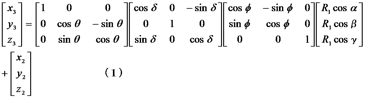
(第2の算出手段112)
次に第2の算出手段112の一例について説明する。第2の算出手段112は、求められた第3の位置の3次元座標(x3、y3、z3)、及び、測定された第1の位置の3次元座標(x1、y1、z1)により、次の式(2)に代入することにより、穿刺針の先端から第2の測定対象までの距離である針長Lを求める。
次に第2の算出手段112の一例について説明する。第2の算出手段112は、求められた第3の位置の3次元座標(x3、y3、z3)、及び、測定された第1の位置の3次元座標(x1、y1、z1)により、次の式(2)に代入することにより、穿刺針の先端から第2の測定対象までの距離である針長Lを求める。

(第3の算出手段113)
次に第3の算出手段113の一例について説明する。穿刺術のために、針先は第3の位置から外され、被検体に刺入される。穿刺術中、位置測定システム300により、第1の位置のXYZ座標、穿刺針の傾斜角が測定される。
第3の算出手段113は、第1の位置のXYZ座標(x11、y11、z11)、X軸、Y軸、Z軸に対する穿刺針の傾斜角λ、μ、ω、及び、針長Lを次の式(3)に代入することにより、針先の位置(x4、y4、z4)を求める。
次に第3の算出手段113の一例について説明する。穿刺術のために、針先は第3の位置から外され、被検体に刺入される。穿刺術中、位置測定システム300により、第1の位置のXYZ座標、穿刺針の傾斜角が測定される。
第3の算出手段113は、第1の位置のXYZ座標(x11、y11、z11)、X軸、Y軸、Z軸に対する穿刺針の傾斜角λ、μ、ω、及び、針長Lを次の式(3)に代入することにより、針先の位置(x4、y4、z4)を求める。
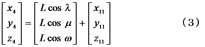
(作成部115)
針長情報取得部100Aは、作成部115を有する。作成部115は、描画用のソフトウェアを有し、このソフトウェアを起動し、第1の位置のXYZ座標、穿刺針の傾斜角、針長、及び、上述する式(3)で表された関数を用いて求められた針先の位置をパラメータとして用いて、針先の位置の画像、焼灼目標範囲の画像を含む、針先を案内するためのガイド情報を作成する。
針長情報取得部100Aは、作成部115を有する。作成部115は、描画用のソフトウェアを有し、このソフトウェアを起動し、第1の位置のXYZ座標、穿刺針の傾斜角、針長、及び、上述する式(3)で表された関数を用いて求められた針先の位置をパラメータとして用いて、針先の位置の画像、焼灼目標範囲の画像を含む、針先を案内するためのガイド情報を作成する。
(パラメータ)
次に、ガイド情報を作成する際に用いられるパラメータについて説明する。パラメータは、穿刺針の種別に対応づけられて記憶部116に予め記憶される。
次に、ガイド情報を作成する際に用いられるパラメータについて説明する。パラメータは、穿刺針の種別に対応づけられて記憶部116に予め記憶される。
パラメータは、穿刺針の仕様を示し、焼灼目標範囲、針ガイドラインの色の濃さ、針ガイドラインの表示/非表示が含まれる。
以下に、穿刺針の種別を単に「針種」という場合がある。針種とは、穿刺針の形態の種類、穿刺針の機能の種類、穿刺針が用いられる検査の種類(検査目的、検査部位を含む)を有する概念である。針種としては、例えば、穿刺針の先端の位置に一つの電極が設けられたモノポーラ型、及び、穿刺針の先端から所定長さ離れた部位に絶縁部を間にして二つの電極が設けられたバイポーラ型がある。
「焼灼目標範囲」には、焼灼目標範囲の形、大きさ、中心位置が含まれる。焼灼目標範囲の「形」、「大きさ」、「中心位置」は、穿刺針の種別(針種)に応じて異なる。「形」に関し、モノポーラ型では円であり、バイポーラ型では楕円である。「大きさ」に関し、モノポーラ型では円における半径であり、バイポーラ型では、楕円における長軸及び短軸の長さである。
「中心位置」は、モノポーラ型では、穿刺針の先端の位置(電極が設けられた位置)である。穿刺針の先端の位置は、前述したように第3の算出手段113により求められる。
さらに、「中心位置」は、バイポーラ型では、穿刺針の先端から所定長さ離れた位置(絶縁部が設けられた位置)である。穿刺針の先端から所定長さ離れた位置についても、第4の算出手段(図示しない)により求められる。
さらに、「中心位置」は、バイポーラ型では、穿刺針の先端から所定長さ離れた位置(絶縁部が設けられた位置)である。穿刺針の先端から所定長さ離れた位置についても、第4の算出手段(図示しない)により求められる。
なお、以下の実施形態では、穿刺針の種別(針種)がモノポーラ型であるとして、焼灼目標範囲の「形」、「大きさ」、「中心位置」を説明する。つまり、「形」は円となり、「中心位置」は穿刺針の先端の位置となる。
「針ガイドラインの色の濃さ」は、ガイドライン下に表示される画像が見づらい場合に薄く表示したりするのに使われる。
「針ガイドラインの表示/非表示」は、ガイドライン下に表示される画像が見やすいか見づらいかに応じて、ガイドラインを表示/非表示するときに使われる。
作成部115は、第3の算出手段113により求められた穿刺針の先端の位置、記憶部116に予め記憶されたパラメータとしての焼灼目標範囲の「形」、「大きさ」を受けて、先端位置を中心とする所定半径の円(焼灼目標範囲)をガイド情報として作成する。
作成部115は、第3の算出手段113により求められた穿刺針の先端の位置、及び、位置測定システムにより測定された穿刺針の第1の位置(磁力センサ310が設けられた位置)に基づいて、針ガイドラインをガイド情報として作成する。
表示処理部118は、記憶部116に予め記憶されたパラメータとしての「針ガイドラインの色の濃さ」、「針ガイドラインの表示/非表示」、及び、作成部115により作成されたガイド情報(ここでは、針ガイドライン)を受けて、針ガイドラインNLを、撮影部により取得されたエコー画像EGに重ねて表示部21に表示/非表示させる。それにより、穿刺針を対象部位に正確かつ容易に刺入することが可能となる。
穿刺術中、位置測定システム300により、第1の位置のXYZ座標(x11、y11、z11)、穿刺針の傾斜角(λ、μ、ω)が測定される。穿刺術中、作成部115の描画用のソフトウェアは継続的に実行され、第1の位置のXYZ座標(x11、y11、z11)、穿刺針の傾斜角(λ、μ、ω)、針長L、及び、前記式(3)で表された関数を用いて求められた針先の位置を用いて、針先の位置の画像、焼灼目標範囲の画像が作成される。並行して、エコー画像EGは、撮影部により取得される。図12は、エコー画像EGに重ねて表示されたガイド情報を示す図である。図12において、エコー画像EGの中に描出された針種の画像を白抜きの部分で示し、エコー画像EGに重ねて表示された針ガイドラインNLを一点鎖線で示す。
図12に示すように、表示処理部118は、作成部115により作成された焼灼目標範囲の座標とエコー画像EGが表示されるときの座標を合わせ、焼灼目標範囲をエコー画像EGに重ねて表示部21に表示させる。焼灼目標範囲が表示されることにより、焼灼目標範囲を対象部位に合わせ易くなる。図12において、エコー画像EGに重ねて表示された焼灼目標範囲TRを示す。
[動作]
次に、超音波診断装置の動作について図13及び図14を参照して説明する。図13は、針長を算出するときの一連の流れを示すフローチャートである。
次に、超音波診断装置の動作について図13及び図14を参照して説明する。図13は、針長を算出するときの一連の流れを示すフローチャートである。
図13に示すように、先ず、針先を第3の位置に当接させる(ステップS101)。このとき、一方の手で超音波プローブ11を持ち、他方の手で穿刺針を持ち、超音波プローブ11と穿刺針とを相互に近づけながら、第3の位置に針先を当接させればよいので、当接させる作業が容易となる。次に、位置測定システム300が第1の位置、第2の位置、及び、超音波プローブ11(撮影部)の傾き角度を測定する(ステップS102)。
以上の第1の位置、第2の位置、超音波プローブ11の傾き角度の測定は、その順番を問わない。これらが測定された後に、針先を第3の位置から外してもよく、超音波プローブ11の傾き角度を変えてもよい。
次に、第1の算出手段111が第2の位置に対する第3の位置の位置関係を、記憶部116から取得する(ステップS103)。次に、第1の算出手段111が第2の位置、及び、超音波プローブ11の傾き角度を取得する(ステップS104)。
次に、第1の算出手段111が、第2の位置に対する第3の位置の位置関係、第2の位置、及び、超音波プローブ11の傾き角度を前記式(1)に代入して、第3の位置を求める(ステップS105)。
次に、第2の算出手段112が、第1の位置を取得する(ステップS106)。次に、第2の算出手段112が、第2の位置及び第3の位置を前記式(2)に代入して、針長を求める(ステップS107)。
針長を求めるための予備測定では、針先を第3の位置に当接させ、位置測定システム300により第1の位置、第2の位置、超音波プローブ11の傾き角度が測定され、測定結果に基づいて、し、針長を求めた。しかし、予備測定後の本測定では、針先は第3の位置から外される。本測定では、位置測定システム300により、第1の位置、穿刺針の傾斜角が測定され、測定結果に基づいて、針先の位置が求められ、作成部115により針先ガイド情報が作成され、針先ガイド情報が表示部21に表示される。
次に、針長が算出されたときから針先ガイド情報を医用画像(エコー画像)に重ねて表示するまでの一連の動作について図14を参照して説明する。図14は、針長が算出されてから針先ガイド情報が表示されるまでの一連の流れを示すフローチャートである。図14に示すように、針長が算出され(ステップS301)、その後に、位置測定システム300が第1の位置のXYZ座標、及び、穿刺針の傾斜角を測定する(ステップS302)。
次に、第3の算出手段113は、針長、第1の位置のXYZ座標、及び、穿刺針の傾斜角を前記式(3)に代入することで、針先の位置を求める(ステップS303)。次に、作成部115は、求められた針先の位置、及び、第1の位置のXYZ座標に基づいて、針ガイドラインを針先ガイド情報として作成する(ステップS304)。このとき、針先ガイド情報としての焼灼目標範囲(その中心位置、形状、大きさを含む)が作成される。
次に、表示処理部118は、焼灼目標範囲の座標をエコー画像EGが表示されるときの座標に変換させる(ステップS305)。次に、表示処理部118は、焼灼目標範囲をエコー画像EGに重ねて表示部21に表示させる(ステップS306)。
(第4の実施形態)
次に、医用画像診断装置の第2実施形態について図1、図15~図21を参照して説明する。なお、第4の実施形態において、第3の実施形態と同じ構成については同一番号を付してその説明を省略し、異なる構成について主に説明する。
次に、医用画像診断装置の第2実施形態について図1、図15~図21を参照して説明する。なお、第4の実施形態において、第3の実施形態と同じ構成については同一番号を付してその説明を省略し、異なる構成について主に説明する。
第3の実施形態においては、第2の位置に対し1つの第3の位置が設けられるため、第2の位置に対する第3の位置の位置関係は1つであった。第3の位置が1つであると、針長を求めるとき、その第3の位置に常に針先を当接させる必要があるため、第3の位置が設けられた所によっては、針先を当接し難い状況が生じるという問題がある。そのため、複数の第3の位置を設け、複数の第3の位置のうちから、針先を当接し易い所を選び、その所に針先を当接するようにすれば、針先を当接し難い状況を回避することが可能となる。
第4の実施形態では、第2の位置に対し複数の第3の位置が設けられる。そのため、第2の位置に対する第3の位置の位置関係は、複数である。つまり、複数の位置関係のうちいずれか1つに特定できなければ、第1の算出手段111は、位置関係に基づいて、第3の位置を求めることができない。
第4の実施形態では、複数の位置関係があるとき、そのうちから1つの位置関係を取得する方法について図15~図19を参照して説明する。図15は、傾斜針の傾斜角と第3の位置との対応関係を示す図、図16は、第2の位置と第3の位置との位置関係を取得するときの一連の流れを示すフローチャート、図17は、針先を第3の位置に当接させた穿刺針の一例を示す図、図18は針先を第3の位置に当接させたときの穿刺針の傾斜角の一例を示す図、図19は、第2の位置と第3の位置との位置関係を示す図である。
第3の位置と穿刺針の傾斜角との対応関係は、記憶部116に予め記憶される。図16に示すように、位置測定システム300は、針先を第3の位置に当接させたときの穿刺針の傾斜角を測定する(ステップS201)。
図17及び図18に示すように、針先が第3の位置に当接されるとき、位置測定システム300は穿刺針の傾斜角ωを測定する。
第1の算出手段111は、XY平面に対する傾斜角ωが-15°~15°の範囲であるとき、図15に示す対応関係を参照して、超音波プローブ11の音響放射面の中央位置である第3の位置を取得する(ステップS202)。
次に、第1の算出手段111は、取得した第3の位置を受けて、図19に示す第2の位置と第3の位置との位置関係を取得する(ステップS203)。このとき、第2の位置と第3の位置とを結ぶ直線の傾き角度は、α1、β1、γ1、及び、直線の長さは、R1である。
以上に、第3の位置を求めるとき、参照される位置関係の一例について説明した。次に、位置関係の他の例について説明する。図20は、針先を第3の位置に当接させた穿刺針の他の例を示す図、図21は、針先を第3の位置に当接させたときの穿刺針の傾斜角の他の例を示す図である。
図20及び図21に示すように、針先が第3の位置に当接されるとき、位置測定システム300は穿刺針の傾斜角ωを測定する。第1の算出手段111は、XY平面に対する傾斜角ωが75°~105°、あるいは、-75°~105°の範囲であるとき、図15に示す対応関係を参照して、超音波プローブ11のマークの位置である第3の位置を取得する(ステップS202)。
次に、第1の算出手段111は、取得した第3の位置を受けて、図19に示す第2の位置と第3の位置との位置関係を取得する(ステップS203)。このとき、第2の位置と第3の位置とを結ぶ直線の傾き角度は、α2、β2、γ2、及び、直線の長さは、R2である。
前記実施形態では、医用画像診断装置として超音波診断装置の例を示し、撮影部として超音波プローブ11の例を示したが、これに限らない。例えば、医用画像診断装置の他の例としてX線CT装置がある。X線CT装置における撮影部の例として、被検体が載置される寝台装置がある。このとき、寝台装置に、第2の位置及び第3の位置が設けられることになる。
さらに、穿刺針に設けられた第1の位置、及び、超音波プローブ11に設けられた第2の位置を測定する測定手段の一例として、位置測定システム300を示したが、第1の位置及び第2の位置の3次元座標及び超音波プローブ11の傾き角度を測定可能なものであれば、どのようなものであってもよい。
さらに、第2の位置と予め定められた位置関係を有する第3の位置に針先を当接させたが、第2の位置に針先を当接させてもよいことはいうまでもない。このとき、第3の位置は第2の位置と等しくなる。
本発明のいくつかの実施形態を説明したが、これら実施形態は、例として提示したものであり、発明の範囲を限定することは意図していない。これら新規な実施形態は、その他の様々な形態で実施されることが可能であり、発明の要旨を逸脱しない範囲で、種々の省略、置き換え、変更を行うことができる。これら実施形態やその変形は、発明の範囲や要旨に含まれるとともに、特許請求の範囲に記載された発明とその均等の範囲に含まれる。
100 医用画像診断装置(超音波診断装置)
10 医用画像診断装置の本体
11 超音波プローブ(支持体)
16 システム制御部
161 演算部
20 穿刺針
21 表示部
22 操作部
30 位置情報取得部
31 トランスミッタ
32,33 位置センサ
34 コントロールユニット
35 伝導体(感応素子)
38 アダプタ
41 感圧センサ(感応素子)
42 接近センサ(感応素子)
200 医用画像診断装置(X線CT装置)
62 システム制御部
621 演算部
72 支持体
100A 針長情報取得部
111 第1の算出手段
112 第2の算出手段
113 第3の算出手段
115 作成部
116 記憶部
118 表示処理部
300 位置測定システム(位置情報取得部)
300a 磁界発生源(トランスミッタ)
310 磁力センサ
320 磁力センサ
330 第3の位置
340 コントロールユニット
10 医用画像診断装置の本体
11 超音波プローブ(支持体)
16 システム制御部
161 演算部
20 穿刺針
21 表示部
22 操作部
30 位置情報取得部
31 トランスミッタ
32,33 位置センサ
34 コントロールユニット
35 伝導体(感応素子)
38 アダプタ
41 感圧センサ(感応素子)
42 接近センサ(感応素子)
200 医用画像診断装置(X線CT装置)
62 システム制御部
621 演算部
72 支持体
100A 針長情報取得部
111 第1の算出手段
112 第2の算出手段
113 第3の算出手段
115 作成部
116 記憶部
118 表示処理部
300 位置測定システム(位置情報取得部)
300a 磁界発生源(トランスミッタ)
310 磁力センサ
320 磁力センサ
330 第3の位置
340 コントロールユニット
Claims (12)
- 被検体に対し超音波の送受波を行う超音波プローブと、
前記超音波プローブに備えられた基準位置部材、及び、穿刺針に対し予め定められた相対位置を有する場所に取り付けられたセンサを含み、前記基準位置部材及び前記センサの位置情報を取得する位置情報取得部と、
前記穿刺針の先端部を前記基準位置部材に当接させたときの前記基準位置部材及び、前記センサの位置情報並びに前記相対位置から前記穿刺針の針長の情報を取得する針長情報取得部と、
前記針長の情報に基づいて前記穿刺針による穿刺を支援する情報を表示する表示部と、
を備える超音波診断装置。 - 前記基準位置部材は、前記穿刺針の先端部が予め設定した距離以内に近づいたときに反応する感応素子であり、
前記針長情報取得部は、前記感応素子が前記穿刺針の先端部に反応するのを契機として、前記基準位置部材及び前記センサの位置情報並びに前記相対位置から前記穿刺針の針長の情報を取得することを特徴とする請求項1に記載の超音波診断装置。 - 前記位置情報取得部は、基準信号を3次元空間上に送信するトランスミッタと、
前記超音波プローブの支持体に取り付けた第1のセンサと、前記穿刺針の任意の位置に取り付けた第2のセンサと、を含み、前記トランスミッタからの基準信号を前記第1、第2のセンサにて受信し、
前記針長情報取得部は、前記第1、第2のセンサの3次元空間上の位置情報と、前記感応素子の反応結果をもとに、前記第2のセンサからの穿刺針の針先までの針長を算出し、
前記表示部は、前記針長の情報をもとに前記穿刺針の穿刺をナビゲートするナビゲーション画像を含む医用画像を表示することを特徴とする請求項2に記載の超音波診断装置。 - 前記感応素子は、前記穿刺針が接することで前記穿刺針からの電流が流れる伝導体で成ることを特徴とする請求項2に記載の超音波診断装置。
- 前記感応素子は、前記穿刺針が接したことを検知する感圧センサで成ることを特徴とする請求項2に記載の超音波診断装置。
- 前記感応素子は、前記穿刺針が接近したことを検知する接近センサ又はカメラで成ることを特徴とする請求項2に記載の超音波診断装置。
- 前記位置情報取得部は、前記穿刺針に前記センサとしての第1の位置が設けられ、前記超音波プローブに、第2の位置、及び、前記第2の位置と予め定められた位置関係を有する第3の位置が設けられ、前記第3の位置に前記穿刺針の先端が合わせられたとき、前記第1の位置の3次元座標、前記第2の位置の3次元座標、及び、前記超音波プローブの傾き角度を測定し、
前記針長情報取得部は、前記超音波プローブにより測定された結果、及び、前記位置関係に基づいて、前記第1の位置から前記穿刺針の先端の位置までの距離であって、穿刺針の先端を案内するガイド情報を表示するための針長を求めることを特徴とする請求項1に記載の超音波診断装置。 - 前記針長情報取得部は、
前記測定された前記第2の位置の3次元座標及び前記超音波プローブの傾き角度に基づき、前記位置関係を参照して、前記第3の位置の3次元座標を求める第1の算出手段と、
前記測定された前記第1の位置の3次元座標、及び、前記求められた前記第3の位置の3次元座標により、前記針長を求める第2の算出手段と、
を有する
ことを特徴とする請求項7に記載の超音波診断装置。 - 前記穿刺針の先端を前記第3の位置に当接させることにより、前記第3の位置に前記穿刺針の先端が合わせられることを特徴とする請求項8に記載の超音波診断装置。
- 前記超音波プローブに複数の前記第3の位置が設けられ、
前記第3の位置と前記穿刺針の傾斜角との対応関係が予め記憶部に記憶され、
前記位置情報取得部は、前記第3の位置に前記穿刺針の先端が合わせられたとき、前記穿刺針の傾斜角を測定し、
前記第1の算出手段は、前記第3の位置の3次元座標を求めるとき、前記測定された前記穿刺針の傾斜角に基づいて、前記対応関係を参照して、前記穿刺針の先端が前記複数の第3の位置のうちのいずれに合わせられたかを判別し、前記判別した前記第3の位置と前記第2の位置との予め定められた前記位置関係を参照することを特徴とする請求項8または請求項9に記載の超音波診断装置。 - 前記位置情報取得部は、前記針長が求められた後における前記穿刺針の傾きを測定し、
前記針長情報取得部は、
前記針長、及び、前記測定された前記穿刺針の傾きに基づいて、前記穿刺針の先端の位置を求める第3の算出手段と、
前記求められた穿刺針の先端の位置に基づいて、前記穿刺針の先端を案内するためのガイド情報を作成する作成部と、
を有し、
前記作成された前記ガイド情報の座標を、被検体の対象部位および対象部位に刺入される穿刺針を撮影して取得された医用画像が表示されるときの座標に合わせる表示処理部をさらに有し、
前記表示部は、前記座標が合わせられた前記ガイド情報を前記医用画像に重ねて表示することを特徴とする請求項7に記載の超音波診断装置。 - 被検体の対象部位および対象部位に刺入される穿刺針を撮影して医用画像を取得する撮影部を有する医用画像診断装置において、
前記撮影部に備えられた基準位置部材、及び、穿刺針に対し予め定められた相対位置を有する場所に取り付けられたセンサを含み、前記基準位置部材及び前記センサの位置情報を取得する位置情報取得部と、
前記穿刺針の先端部を前記基準位置部材に当接させたときの前記基準位置部材及び、前記センサの位置情報並びに前記相対位置から前記穿刺針の針長の情報を取得する針長情報取得部と、
前記針長の情報に基づいて前記穿刺針による穿刺を支援する情報を表示する表示部と、
を備える医用画像診断装置。
Priority Applications (1)
| Application Number | Priority Date | Filing Date | Title |
|---|---|---|---|
| US14/956,904 US10363013B2 (en) | 2013-06-11 | 2015-12-02 | Ultrasound diagnosis apparatus and medical image diagnosis apparatus |
Applications Claiming Priority (4)
| Application Number | Priority Date | Filing Date | Title |
|---|---|---|---|
| JP2013-122692 | 2013-06-11 | ||
| JP2013122692 | 2013-06-11 | ||
| JP2014-076290 | 2014-04-02 | ||
| JP2014076290 | 2014-04-02 |
Related Child Applications (1)
| Application Number | Title | Priority Date | Filing Date |
|---|---|---|---|
| US14/956,904 Continuation US10363013B2 (en) | 2013-06-11 | 2015-12-02 | Ultrasound diagnosis apparatus and medical image diagnosis apparatus |
Publications (1)
| Publication Number | Publication Date |
|---|---|
| WO2014199799A1 true WO2014199799A1 (ja) | 2014-12-18 |
Family
ID=52022100
Family Applications (1)
| Application Number | Title | Priority Date | Filing Date |
|---|---|---|---|
| PCT/JP2014/063662 Ceased WO2014199799A1 (ja) | 2013-06-11 | 2014-05-23 | 超音波診断装置及び医用画像診断装置 |
Country Status (3)
| Country | Link |
|---|---|
| US (1) | US10363013B2 (ja) |
| JP (1) | JP6282934B2 (ja) |
| WO (1) | WO2014199799A1 (ja) |
Cited By (2)
| Publication number | Priority date | Publication date | Assignee | Title |
|---|---|---|---|---|
| CN114052851A (zh) * | 2021-03-03 | 2022-02-18 | 武汉联影医疗科技有限公司 | 穿刺导航仪、穿刺路径规划方法和穿刺导航系统 |
| CN115054332A (zh) * | 2022-06-17 | 2022-09-16 | 南京医科大学 | 一种超声引导机器人辅助穿刺装置及其使用方法 |
Families Citing this family (25)
| Publication number | Priority date | Publication date | Assignee | Title |
|---|---|---|---|---|
| US9701530B2 (en) | 2013-11-22 | 2017-07-11 | Michael J. Kline | System, method, and apparatus for purchasing, dispensing, or sampling of products |
| US10657780B1 (en) | 2015-01-29 | 2020-05-19 | Transparensee Llc | System, method, and apparatus for mixing, blending, dispensing, monitoring, and labeling products |
| US11322048B2 (en) * | 2015-09-15 | 2022-05-03 | University Of Florida Research Foundation, Incorporated | Ultrasound-guided medical tool insertion simulators |
| US10548666B2 (en) * | 2015-11-17 | 2020-02-04 | Covidien Lp | Systems and methods for ultrasound image-guided ablation antenna placement |
| WO2017108490A1 (en) * | 2015-12-22 | 2017-06-29 | Koninklijke Philips N.V. | Ultrasound based tracking |
| KR102530174B1 (ko) * | 2016-01-21 | 2023-05-10 | 삼성메디슨 주식회사 | 초음파 영상 장치 및 그 제어 방법 |
| KR101931747B1 (ko) * | 2016-10-28 | 2019-03-13 | 삼성메디슨 주식회사 | 생체 검사 장치 및 동작 방법 |
| US11534243B2 (en) * | 2016-11-23 | 2022-12-27 | Clear Guide Medical, Inc. | System and methods for navigating interventional instrumentation |
| US10376235B2 (en) * | 2016-12-21 | 2019-08-13 | Industrial Technology Research Institute | Needle guide system and medical intervention system |
| US11583249B2 (en) * | 2017-09-08 | 2023-02-21 | Biosense Webster (Israel) Ltd. | Method and apparatus for performing non-fluoroscopic transseptal procedure |
| KR102085588B1 (ko) * | 2018-02-09 | 2020-03-06 | 고려대학교 산학협력단 | 시술도구 위치 추적 시스템 |
| KR102077660B1 (ko) * | 2018-04-06 | 2020-02-14 | 계명대학교 산학협력단 | 초음파 유도하에 입구가 막힌 천부 대퇴동맥을 직접 천자하는 시스템, 및 그 이용방법 |
| JP7460613B2 (ja) * | 2018-10-25 | 2024-04-02 | コーニンクレッカ フィリップス エヌ ヴェ | 音響撮像における介入装置の先端の場所を推定するためのシステム、装置及び方法 |
| US11801113B2 (en) | 2018-12-13 | 2023-10-31 | Covidien Lp | Thoracic imaging, distance measuring, and notification system and method |
| US11617493B2 (en) | 2018-12-13 | 2023-04-04 | Covidien Lp | Thoracic imaging, distance measuring, surgical awareness, and notification system and method |
| EP3946127B1 (en) | 2019-03-25 | 2025-12-31 | Fusmobile, Inc. | SYSTEMS AND METHODS FOR AIMING AND ALIGNING A PROCESSING TOOL IN AN X-RAY DEVICE |
| CN110200683B (zh) * | 2019-07-03 | 2025-02-25 | 北京积水潭医院 | 超声引导下穿刺姿态监测方法及装置 |
| EP4699545A3 (en) * | 2019-08-16 | 2026-04-22 | FUJIFILM Corporation | Ultrasound diagnostic apparatus and control method of ultrasound diagnostic apparatus |
| CN111839683B (zh) * | 2020-07-27 | 2022-03-22 | 南通市第一人民医院 | 一种前列腺穿刺定位辅助器 |
| CN113768538A (zh) * | 2021-09-15 | 2021-12-10 | 上海益超医疗器械有限公司 | 用于双平面超声探头装置的检测控制方法、装置及其系统 |
| CN113855071B (zh) * | 2021-09-28 | 2023-05-30 | 核工业总医院 | 一种改进的超声诊断设备和显示超声图像的方法 |
| CN115553880B (zh) * | 2022-03-29 | 2024-08-16 | 中国人民解放军总医院第一医学中心 | 一种穿刺针尖的定位方法和系统 |
| JP2024024283A (ja) * | 2022-08-09 | 2024-02-22 | コニカミノルタ株式会社 | 超音波診断装置 |
| CN116585032B (zh) * | 2023-05-09 | 2025-10-03 | 上海美微达医疗科技有限公司 | 基于导航系统的微创穿刺系统 |
| CN117137628B (zh) * | 2023-09-26 | 2024-08-30 | 磅客策(上海)智能医疗科技有限公司 | 一种基于磁导航的活检针及活检方法 |
Citations (3)
| Publication number | Priority date | Publication date | Assignee | Title |
|---|---|---|---|---|
| JP2001526927A (ja) * | 1997-12-31 | 2001-12-25 | ウルトラガイド・リミテッド | スキャニングトランスデューサ上の位置センサをキャリブレーションする方法及び装置 |
| JP2005058584A (ja) * | 2003-08-19 | 2005-03-10 | Toshiba Corp | 超音波診断装置 |
| JP2007000226A (ja) * | 2005-06-22 | 2007-01-11 | Toshiba Corp | 医用画像診断装置 |
Family Cites Families (7)
| Publication number | Priority date | Publication date | Assignee | Title |
|---|---|---|---|---|
| EP0845959A4 (en) * | 1995-07-16 | 1998-09-30 | Ultra Guide Ltd | HAND-FREE DRAWING A NEEDLE GUIDE |
| US8123691B2 (en) | 2003-08-19 | 2012-02-28 | Kabushiki Kaisha Toshiba | Ultrasonic diagnostic apparatus for fixedly displaying a puncture probe during 2D imaging |
| JP2005253742A (ja) * | 2004-03-12 | 2005-09-22 | Matsushita Electric Ind Co Ltd | 超音波診断装置 |
| US20060063998A1 (en) * | 2004-09-21 | 2006-03-23 | Von Jako Ron | Navigation and visualization of an access needle system |
| JP4812458B2 (ja) | 2006-02-15 | 2011-11-09 | 株式会社東芝 | 超音波診断装置及び治療支援装置 |
| JP4357573B2 (ja) | 2008-03-10 | 2009-11-04 | 株式会社東芝 | 超音波診断装置 |
| US8556815B2 (en) * | 2009-05-20 | 2013-10-15 | Laurent Pelissier | Freehand ultrasound imaging systems and methods for guiding fine elongate instruments |
-
2014
- 2014-05-23 WO PCT/JP2014/063662 patent/WO2014199799A1/ja not_active Ceased
- 2014-05-23 JP JP2014106791A patent/JP6282934B2/ja not_active Expired - Fee Related
-
2015
- 2015-12-02 US US14/956,904 patent/US10363013B2/en active Active
Patent Citations (3)
| Publication number | Priority date | Publication date | Assignee | Title |
|---|---|---|---|---|
| JP2001526927A (ja) * | 1997-12-31 | 2001-12-25 | ウルトラガイド・リミテッド | スキャニングトランスデューサ上の位置センサをキャリブレーションする方法及び装置 |
| JP2005058584A (ja) * | 2003-08-19 | 2005-03-10 | Toshiba Corp | 超音波診断装置 |
| JP2007000226A (ja) * | 2005-06-22 | 2007-01-11 | Toshiba Corp | 医用画像診断装置 |
Cited By (2)
| Publication number | Priority date | Publication date | Assignee | Title |
|---|---|---|---|---|
| CN114052851A (zh) * | 2021-03-03 | 2022-02-18 | 武汉联影医疗科技有限公司 | 穿刺导航仪、穿刺路径规划方法和穿刺导航系统 |
| CN115054332A (zh) * | 2022-06-17 | 2022-09-16 | 南京医科大学 | 一种超声引导机器人辅助穿刺装置及其使用方法 |
Also Published As
| Publication number | Publication date |
|---|---|
| JP6282934B2 (ja) | 2018-02-21 |
| JP2015198888A (ja) | 2015-11-12 |
| US10363013B2 (en) | 2019-07-30 |
| US20160081653A1 (en) | 2016-03-24 |
Similar Documents
| Publication | Publication Date | Title |
|---|---|---|
| JP6282934B2 (ja) | 超音波診断装置及び医用画像診断装置 | |
| JP5738507B2 (ja) | 超音波プローブの軌跡表現装置及び超音波診断装置 | |
| CN114081597B (zh) | 一种穿刺装置、超声成像设备和辅助穿刺的方法 | |
| CN104981208B (zh) | 超声波诊断装置及其控制程序 | |
| JP6081299B2 (ja) | 超音波診断装置 | |
| CN100469319C (zh) | 超声波图像取得装置以及超声波低衰减介质 | |
| US20170095226A1 (en) | Ultrasonic diagnostic apparatus and medical image diagnostic apparatus | |
| CN104994792B (zh) | 超声波诊断装置以及医用图像处理装置 | |
| JP6305810B2 (ja) | 医用画像診断装置 | |
| JP6162493B2 (ja) | 超音波診断装置 | |
| JP2010051817A (ja) | 超音波装置、超音波撮像プログラム及び超音波撮像方法 | |
| JP2005529701A (ja) | 撮像装置の撮像パターンのコンピュータで生成した表示 | |
| JP6386733B2 (ja) | X線診断装置及び超音波診断装置 | |
| JP5462076B2 (ja) | 超音波診断装置および画像情報管理装置 | |
| JP5954786B2 (ja) | 超音波診断装置及び画像データの表示制御プログラム | |
| US20180092629A1 (en) | Ultrasound diagnosis apparatus, medical image diagnosis apparatus, and computer program product | |
| CN107041761A (zh) | 超声波诊断装置、旋转式探头的姿态计算装置及其方法 | |
| JP2018000775A (ja) | 超音波診断装置、及び医用画像処理装置 | |
| JP2013118998A (ja) | 医用画像診断装置、超音波診断装置及びプログラム | |
| JP2018192246A (ja) | 超音波診断装置および超音波診断支援プログラム | |
| JP2018134197A (ja) | 医用手技ナビゲーションシステムおよび方法 | |
| CN103142246B (zh) | 超声波诊断装置及坐标转换方法 | |
| JP2014161598A (ja) | 超音波診断装置及びその制御プログラム | |
| JP6462331B2 (ja) | 超音波診断装置、医用画像処理装置及び画像診断システム | |
| JP2016043128A (ja) | 超音波診断装置及び制御プログラム |
Legal Events
| Date | Code | Title | Description |
|---|---|---|---|
| 121 | Ep: the epo has been informed by wipo that ep was designated in this application |
Ref document number: 14811603 Country of ref document: EP Kind code of ref document: A1 |
|
| NENP | Non-entry into the national phase |
Ref country code: DE |
|
| 122 | Ep: pct application non-entry in european phase |
Ref document number: 14811603 Country of ref document: EP Kind code of ref document: A1 |