WO2014199551A1 - 映像符号化装置、映像符号化方法および映像符号化プログラム - Google Patents
映像符号化装置、映像符号化方法および映像符号化プログラム Download PDFInfo
- Publication number
- WO2014199551A1 WO2014199551A1 PCT/JP2014/002252 JP2014002252W WO2014199551A1 WO 2014199551 A1 WO2014199551 A1 WO 2014199551A1 JP 2014002252 W JP2014002252 W JP 2014002252W WO 2014199551 A1 WO2014199551 A1 WO 2014199551A1
- Authority
- WO
- WIPO (PCT)
- Prior art keywords
- coefficient
- coefficient level
- significant
- orthogonal transform
- level
- Prior art date
Links
Images


Classifications
-
- H—ELECTRICITY
- H04—ELECTRIC COMMUNICATION TECHNIQUE
- H04N—PICTORIAL COMMUNICATION, e.g. TELEVISION
- H04N19/00—Methods or arrangements for coding, decoding, compressing or decompressing digital video signals
- H04N19/10—Methods or arrangements for coding, decoding, compressing or decompressing digital video signals using adaptive coding
- H04N19/169—Methods or arrangements for coding, decoding, compressing or decompressing digital video signals using adaptive coding characterised by the coding unit, i.e. the structural portion or semantic portion of the video signal being the object or the subject of the adaptive coding
- H04N19/18—Methods or arrangements for coding, decoding, compressing or decompressing digital video signals using adaptive coding characterised by the coding unit, i.e. the structural portion or semantic portion of the video signal being the object or the subject of the adaptive coding the unit being a set of transform coefficients
-
- H—ELECTRICITY
- H04—ELECTRIC COMMUNICATION TECHNIQUE
- H04N—PICTORIAL COMMUNICATION, e.g. TELEVISION
- H04N19/00—Methods or arrangements for coding, decoding, compressing or decompressing digital video signals
- H04N19/10—Methods or arrangements for coding, decoding, compressing or decompressing digital video signals using adaptive coding
- H04N19/102—Methods or arrangements for coding, decoding, compressing or decompressing digital video signals using adaptive coding characterised by the element, parameter or selection affected or controlled by the adaptive coding
- H04N19/124—Quantisation
-
- H—ELECTRICITY
- H04—ELECTRIC COMMUNICATION TECHNIQUE
- H04N—PICTORIAL COMMUNICATION, e.g. TELEVISION
- H04N19/00—Methods or arrangements for coding, decoding, compressing or decompressing digital video signals
- H04N19/10—Methods or arrangements for coding, decoding, compressing or decompressing digital video signals using adaptive coding
- H04N19/134—Methods or arrangements for coding, decoding, compressing or decompressing digital video signals using adaptive coding characterised by the element, parameter or criterion affecting or controlling the adaptive coding
- H04N19/136—Incoming video signal characteristics or properties
- H04N19/14—Coding unit complexity, e.g. amount of activity or edge presence estimation
-
- H—ELECTRICITY
- H04—ELECTRIC COMMUNICATION TECHNIQUE
- H04N—PICTORIAL COMMUNICATION, e.g. TELEVISION
- H04N19/00—Methods or arrangements for coding, decoding, compressing or decompressing digital video signals
- H04N19/10—Methods or arrangements for coding, decoding, compressing or decompressing digital video signals using adaptive coding
- H04N19/134—Methods or arrangements for coding, decoding, compressing or decompressing digital video signals using adaptive coding characterised by the element, parameter or criterion affecting or controlling the adaptive coding
- H04N19/146—Data rate or code amount at the encoder output
-
- H—ELECTRICITY
- H04—ELECTRIC COMMUNICATION TECHNIQUE
- H04N—PICTORIAL COMMUNICATION, e.g. TELEVISION
- H04N19/00—Methods or arrangements for coding, decoding, compressing or decompressing digital video signals
- H04N19/70—Methods or arrangements for coding, decoding, compressing or decompressing digital video signals characterised by syntax aspects related to video coding, e.g. related to compression standards
-
- H—ELECTRICITY
- H04—ELECTRIC COMMUNICATION TECHNIQUE
- H04N—PICTORIAL COMMUNICATION, e.g. TELEVISION
- H04N19/00—Methods or arrangements for coding, decoding, compressing or decompressing digital video signals
- H04N19/90—Methods or arrangements for coding, decoding, compressing or decompressing digital video signals using coding techniques not provided for in groups H04N19/10-H04N19/85, e.g. fractals
- H04N19/91—Entropy coding, e.g. variable length coding [VLC] or arithmetic coding
-
- H—ELECTRICITY
- H04—ELECTRIC COMMUNICATION TECHNIQUE
- H04N—PICTORIAL COMMUNICATION, e.g. TELEVISION
- H04N19/00—Methods or arrangements for coding, decoding, compressing or decompressing digital video signals
- H04N19/90—Methods or arrangements for coding, decoding, compressing or decompressing digital video signals using coding techniques not provided for in groups H04N19/10-H04N19/85, e.g. fractals
- H04N19/96—Tree coding, e.g. quad-tree coding
-
- H—ELECTRICITY
- H04—ELECTRIC COMMUNICATION TECHNIQUE
- H04N—PICTORIAL COMMUNICATION, e.g. TELEVISION
- H04N19/00—Methods or arrangements for coding, decoding, compressing or decompressing digital video signals
- H04N19/10—Methods or arrangements for coding, decoding, compressing or decompressing digital video signals using adaptive coding
- H04N19/134—Methods or arrangements for coding, decoding, compressing or decompressing digital video signals using adaptive coding characterised by the element, parameter or criterion affecting or controlling the adaptive coding
- H04N19/146—Data rate or code amount at the encoder output
- H04N19/147—Data rate or code amount at the encoder output according to rate distortion criteria
-
- H—ELECTRICITY
- H04—ELECTRIC COMMUNICATION TECHNIQUE
- H04N—PICTORIAL COMMUNICATION, e.g. TELEVISION
- H04N19/00—Methods or arrangements for coding, decoding, compressing or decompressing digital video signals
- H04N19/60—Methods or arrangements for coding, decoding, compressing or decompressing digital video signals using transform coding
- H04N19/63—Methods or arrangements for coding, decoding, compressing or decompressing digital video signals using transform coding using sub-band based transform, e.g. wavelets
- H04N19/64—Methods or arrangements for coding, decoding, compressing or decompressing digital video signals using transform coding using sub-band based transform, e.g. wavelets characterised by ordering of coefficients or of bits for transmission
- H04N19/647—Methods or arrangements for coding, decoding, compressing or decompressing digital video signals using transform coding using sub-band based transform, e.g. wavelets characterised by ordering of coefficients or of bits for transmission using significance based coding, e.g. Embedded Zerotrees of Wavelets [EZW] or Set Partitioning in Hierarchical Trees [SPIHT]
Definitions
- the present invention relates to a technique for simultaneously quantizing orthogonal transform coefficients that are continuous in the transmission order.
- each frame of the digitized video is divided into coding tree units (CTU: Coding Tree Unit), and each CTU is encoded in raster scan order. It becomes.
- CTU is divided into coding units (CU: Coding Unit) in a quad tree structure and encoded.
- CU Coding Unit
- Each CU is predicted by being divided into prediction units (PU: Prediction Unit).
- PU Prediction Unit
- the prediction error of each CU is divided into transform units (TU: Transform Unit) in a quadtree structure, and is subjected to frequency conversion.
- CU is a coding unit for intra prediction / interframe prediction.
- intra prediction and inter-frame prediction will be described.
- Intra prediction is prediction generated from the reconstructed image of the encoding target frame.
- Non-Patent Document 1 defines 33 types of angle intra prediction shown in FIG.
- an intra prediction signal is generated by extrapolating the reconstructed pixels around the encoding target block in any of the 33 types of directions shown in FIG.
- a CU that uses intra prediction is referred to as an intra CU.
- Inter-frame prediction is prediction based on an image of a reconstructed frame (reference picture) having a display time different from that of an encoding target frame.
- inter-frame prediction is also referred to as inter prediction.
- FIG. 10 is an explanatory diagram illustrating an example of inter-frame prediction.
- the motion vector MV (mv x , mv y ) indicates the parallel movement amount of the reconstructed image block of the reference picture with respect to the encoding target block.
- Inter prediction generates an inter prediction signal based on a reconstructed image block of a reference picture (using pixel interpolation if necessary).
- a CU using inter prediction is referred to as an inter CU.
- a frame encoded only by the intra CU is called an I frame (or I picture).
- a frame encoded including not only an intra CU but also an inter CU is called a P frame (or P picture).
- a frame that is encoded including not only one reference picture for inter prediction of a block but also an inter CU that uses two reference pictures at the same time is called a B frame (or B picture).
- 11 includes a frequency converter 101, a quantizer 1020, an entropy encoder 103, an inverse frequency transformer / inverse quantizer 104, a buffer 105, a predictor 106, and an estimator 107.
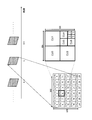
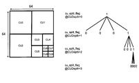
- FIG. 12 illustrates an example of CTU partitioning of the t-th frame when the spatial resolution of the frame is CIF (Common Intermediate Format) and a CTU size of 64, and an example of CU partitioning of the eighth CTU (CTU8)
- FIG. 13 is an explanatory diagram showing a quadtree structure corresponding to the CU partitioning example of CTU8.
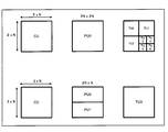
- FIG. 14 is an explanatory diagram showing an example of TU partitioning of a CU.
- the upper part shows an example of intra prediction 2N ⁇ 2N PU CU TU partitioning.
- the CU is an intra prediction
- the root of the quad tree is arranged in the PU, and the prediction error is expressed by a quad tree structure.
- the bottom row shows an example of inter prediction 2N ⁇ N PU CU TU partitioning.
- the root of the quad tree is placed in the CU, and the prediction error is expressed by a quad tree structure.
- the estimator 107 determines a CU quadtree structure, a PU partition shape, and a TU quadtree structure for each CTU.
- the predictor 106 generates a prediction signal for the input image signal of the CU based on the CU quadtree structure and the PU partition shape determined by the estimator 107.
- the prediction signal is generated based on the above-described intra prediction or inter prediction.
- the frequency converter 101? Performs frequency conversion on the prediction error image obtained by subtracting the prediction signal from the input image signal based on the TU quadtree structure determined by the estimator 107 ?.
- the quantizer 1020 quantizes the frequency-transformed prediction error image (orthogonal transform coefficient).
- the quantized orthogonal transform coefficient is referred to as a coefficient level.
- a coefficient level having a value other than 0 is called a significant coefficient level.
- the quantizer 1020 includes a coefficient level calculation unit 1201 that receives an orthogonal transform coefficient Kij and a quantization parameter QP and outputs a coefficient level Lij.
- the entropy encoder 103 entropy-encodes cu_split_flag indicating a CTU quadtree structure, a prediction parameter, and a coefficient level.
- the inverse frequency transform / inverse quantizer 104 dequantizes the coefficient level. Further, the inverse frequency transform / inverse quantizer 104 performs inverse frequency transform on the inversely quantized orthogonal transform coefficient.
- the reconstructed prediction error image subjected to the inverse frequency conversion is supplied with a prediction signal and supplied to the buffer 105.
- the buffer 105 stores the reconstructed image.
- a general video encoding device Based on the above-described operation, a general video encoding device generates a bit stream.
- FIG. 16 is an explanatory diagram showing an example in which Kij is quantized with Qs having a value of 4096 and a parameter f having a value of 1/3.
- the operations of the quantizer 1020 and the entropy encoder 103 will be described in detail using the example of 4 ⁇ 4 TU shown in FIG.
- an orthogonal transformation coefficient Kij and a coefficient level Lij of 4 ⁇ 4 TU are defined as follows.
- Kij (0 ⁇ i, j ⁇ 3) is defined as the value of the orthogonal transformation coefficient at the horizontal position i and the vertical position j on the frequency axis.
- the coefficient level Lij is defined as the value of the coefficient level corresponding to the orthogonal transformation coefficient Kij.
- Kij and Lij are higher frequency components.
- the coefficient level calculation unit 1201 calculates the coefficient level Lij by dividing Kij by the quantization step Qs. Formally, the coefficient level Lij is expressed by equation (1).
- Lij Sign (Kij) / Floor (
- Sign (a) is a function that returns the sign of the input a
- Floor (a) is a function that returns the largest integer less than or equal to the input a
- f is a parameter that determines the quantization characteristics (0 ⁇ f ⁇ 0.5). is there.
- the value of f is 1/6 for inter prediction and 1/3 for intra prediction.
- N is the block size of TU.
- N 4.
- FIG. 16 shows an example in which Kij is quantized with Qs having a value of 4096 and f having a value of 1/3.
- the position information is information indicating the positions of all significant coefficient levels included in the TU.
- position information in HEVC includes information last_significant_x and last_significant_y indicating the horizontal position and vertical position of the significant coefficient level to be transmitted first, and (last_significant_x, last_significant_y) Further, it is composed of information siginificant_coeff_flag indicating presence / absence of a significant coefficient level at each of the subsequent positions to (0, 0). Therefore, the number of position information bits is the sum of the number of bits of last_significant_x, the number of bits of last_significant_y, and the number of bits of siginificant_coeff_flag determined based on the position of the significant coefficient level to be transmitted first.
- value information is information indicating the value of the significant coefficient level.
- the value information in HEVC is information coeff_abs_level_greater1_flag indicating whether or not the absolute value of the significant coefficient level is greater than 1, whether or not the absolute value of the significant coefficient level is greater than 2.
- This information is composed of coeff_abs_level_remaining information.
- the number of value information bits is the sum of the number of bits of coeff_abs_level_greater1_flag, the number of bits of coeff_abs_level_greater2_flag, the number of bits of coeff_sign_flag, and the number of bits of coeff_abs_level_remaining.
- Table 1 shows the relationship between position information and value information and coefficient level Lij.
- Table 1 IV the items on the vertical axis with respect to the horizontal axis indicate information on each Lij in the 4 ⁇ 4 TU shown in FIG.
- siginificant_coeff_flag indicates the presence / absence of a significant coefficient level at each position from (3, 0) to (0, 0).
- siginificant_coeff_flag 1
- siginificant_coeff_flag 0.
- Table 2 (b) shows the relationship between position information, value information, and the number of bits of value information.
- the items on the vertical axis relative to the horizontal axis indicate the number of position information bits and value information bits of 4 ⁇ 4 TU shown in FIG.
- bin refers to one bit in the intermediate bit string before being converted to the bitstream output by the entropy encoder 103.
- the entropy encoder 103 ⁇ ⁇ transmits bit 13bin of the position information of all the significant coefficient levels in the TU and then the value information bits of each significant coefficient level. A total of 4 bins are transmitted.
- the position information is composed of last_significant_x, last_significant_y and siginificant_coeff_flag.
- siginificant_coeff_flag indicates the presence / absence of a significant coefficient level at each of the 9 positions from the position (2, 1) to (0, 0) following the position of the first significant coefficient to be transmitted, and is 9 bin.
- the value information is composed of coeff_abs_level_greater1_flag, coeff_abs_level_greater2_flag, coeff_sign_flag, and coeff_abs_level_remaining.
- coeff_abs_level_greater1_flag compared L 30 and L 01, are 2bin indicate whether 1 or greater.
- coeff_abs_level_greater2_flag is 0bin because there is no coefficient level with an absolute value of a significant coefficient level greater than 2.
- coeff_sign_flag indicates the sign of L 30 and L 01 and is 2 bins.
- coeff_abs_level_remaining is 0bin because there is no coefficient level with an absolute value of the significant coefficient level greater than 2.
- Non-Patent Document 1 Based on 7.3.8.11 of Non-Patent Document 1, there is a maximum of 16 per 4x4 TU, so coeff_sign_flag is 16 bins at maximum. Based on 9.3.3.9 of Non-Patent Document 1, bin for coeff_abs_level_remaining is calculated.
- the quantizer of the general video encoding device described above may generate a high cost coefficient level.
- the high cost coefficient level is a significant coefficient level that generates a large number of bits after entropy coding despite not improving the signal-noise ratio.
- a typical example is a significant coefficient level having a small value and a large number of bits of position information.
- the above-described general video encoding apparatus has a problem that the compression efficiency is lowered by the transmission of the high cost coefficient level output from the quantizer.
- Non-Patent Document 2 it is possible to prevent the occurrence of a high cost coefficient level by quantizing the orthogonal transform coefficient in consideration of the number of bits of value information and the number of bits of position information.
- the calculation of the number of position information bits described in Non-Patent Document 2 uses information on whether or not the quantizer has output a significant coefficient level until immediately before. Therefore, when the occurrence of a high cost coefficient level is prevented using the number of bits of position information, a plurality of coefficient levels that are consecutive in the transmission order cannot be determined simultaneously. That is, parallel quantization processing cannot be performed.
- a video encoding apparatus that cannot perform parallel quantization processing needs to maintain processing performance by raising the clock frequency, which increases power consumption.
- the present invention simultaneously determines a plurality of coefficient levels that are consecutive in the transmission order in consideration of the number of bits of value information and position information, and thereby achieves both a compression efficiency reduction prevention and a parallel quantization process of a plurality of orthogonal transform coefficients.
- An object is to provide an encoding device, a video encoding method, and a video encoding program.
- a video encoding apparatus includes an orthogonal transform unit that orthogonally transforms an image block to calculate an orthogonal transform coefficient, a quantization unit that quantizes the orthogonal transform coefficient to calculate a coefficient level, and all of the coefficient levels.
- Entropy encoding means for entropy encoding the position information of each significant coefficient level and then entropy encoding the value information of each significant coefficient level to output a bitstream, and the quantization means is a processing target in the image block.
- the value information bit number calculating means for calculating the value information bit number of the significant coefficient level of the orthogonal transform coefficient to be monitored, and the coefficient level output by the quantizing means from the first N bits before in the transmission order in the image block, State variable update means for updating a state variable indicating whether or not at least one of them is significant, and orthogonal transformation to be processed Position information bit number calculating means for calculating the number of position information bits of the significant coefficient level of the orthogonal transform coefficient to be processed based on the position of the number and the state variable, and the number of value information bits and the number of position information bits are predetermined. And a high cost coefficient level detecting / removing means for setting a significant coefficient level satisfying the above condition to 0.
- the video coding method orthogonally transforms an image block to calculate orthogonal transform coefficients, quantize the orthogonal transform coefficients to calculate coefficient levels, and entropy the position information of all significant coefficient levels among the coefficient levels.
- the number of significant coefficient level value information bits is calculated, and a state variable indicating whether or not at least one of the coefficient levels from the top to the previous N blocks in the transmission order in the image block is significant is updated, Calculates the number of position information bits at the significant coefficient level of the orthogonal transform coefficient to be processed based on the position of the orthogonal transform coefficient to be processed and the state variable , And the number of position information bits and the number of values of information bits, characterized in that the 0 satisfying a predetermined condition significant coefficient level.
- the video encoding program allows a computer to orthogonally transform an image block to calculate orthogonal transform coefficients, to quantize the orthogonal transform coefficients to calculate coefficient levels, and to calculate all significant values among the coefficient levels.
- the processing target in the image block State variable that indicates whether or not at least one of the coefficient levels from the beginning to the Nth preceding in the transmission order in the image block is significant, and the process of calculating the value information bit number of the significant coefficient level of the orthogonal transform coefficient Based on the processing to update the position of the orthogonal transformation coefficient to be processed and the state variable.
- a process of calculating the number of position information bits of a significant coefficient level of a transform coefficient and a process of setting a significant coefficient level satisfying a predetermined condition between a value information bit number and a position information bit number to 0 are executed. .
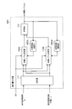
- FIG. 1 is a block diagram showing a first embodiment of a video encoding device according to the present invention.
- FIG. It is a block diagram which shows the structure of the adaptive quantizer in 1st Embodiment. It is a flowchart which shows operation
- FIG. 6 is an explanatory diagram showing an example of CTU partitioning of frame t and a CU partitioning example of CTU8 of frame t. It is explanatory drawing which shows the quadtree structure corresponding to the CU division
- the video encoding device is not information on whether or not the quantizer has output a significant coefficient level until immediately before, but from the head in the transmission order to N (N ⁇ 2) before processing.
- the number of position information bits is calculated using information on whether or not the quantizer outputs a significant coefficient level.
- the video encoding apparatus can calculate the number of position information bits without using the immediately preceding N ⁇ 1 coefficient levels, and can perform parallel processing.
- the probability of erroneously estimating the number of transmission bits ⁇ R by mistake is the probability that the quantizer outputs all 0 from the beginning of the TU to N (N ⁇ 2) before the processing target M, and the N immediately before the processing target.
- the product of the probabilities that one of the -1 coefficient levels is a significant coefficient level. Since the former probability is a direct product of values less than 1, it becomes smaller as it reaches the end in the transmission order, that is, as the frequency component of the coefficient level becomes lower.
- the coefficient level tends to be biased to 0, the probability of the latter also becomes a small value. Since the probability of erroneously estimating the number of position information bits is low, the probability of removing a coefficient level that is not a high cost coefficient level is also low.
- the video encoding device calculates the number of position information bits for each significant coefficient level using coefficient levels output from the quantizer from the beginning of the image block to the previous N blocks in the transmission order, and N consecutive temporary blocks. Since the coefficient level to be quantized and output can be determined in consideration of the number of bits of position information and value information at the same time with respect to the coefficient level, it is possible to achieve both compression efficiency reduction prevention and parallel quantization processing of a plurality of orthogonal transform coefficients.
- FIG. FIG. 1 is a block diagram showing a first embodiment of a video encoding apparatus according to the present invention.
- the configuration of a video encoding apparatus according to a first embodiment that outputs a bit stream using each frame of a digitized video as an input image will be described.
- the video encoding apparatus regards a coefficient level in which the number of position information bits is larger than the number of value information bits as a high-cost coefficient level, and simultaneously quantizes N consecutive orthogonal transform coefficients.
- the video encoding apparatus simultaneously determines a plurality of coefficient levels that are consecutive in the transmission order in consideration of the number of bits of value information and the number of bits of position information, thereby preventing reduction in compression efficiency and parallel quantization of a plurality of orthogonal transform coefficients. Both of the conversion process.
- the video encoding apparatus shown in FIG. 1B includes a frequency converter 101, an adaptive quantizer 1021, an entropy encoder 103, an inverse frequency transformer / inverse quantizer 104, a buffer 105, a predictor 106, and an estimator 107. .
- an adaptive quantizer 1021 is provided instead of the quantizer 1020.
- Other blocks in the video encoding device shown in FIG. 1B are the same as the blocks in the video encoding device shown in FIG. Therefore, only the adaptive quantizer 1021 will be described below.
- FIG. 2 is a block diagram showing the configuration of adaptive quantizer 1021.
- the adaptive quantizer shown in FIG. 2 includes a value information bit number calculation unit (R value calculation unit) 1202, a position information bit number calculation unit (R position ) in addition to the coefficient level calculation unit 1201 of the quantizer shown in FIG. A calculation unit) 1203, a high cost coefficient level detection / removal unit 1204, and a state variable update unit (StateFlag update unit) 1205.
- the coefficient level calculation unit 1201, the value information bit number calculation unit (R value calculation unit) 1202, the position information bit number calculation unit (R position calculation unit) 1203, and the high cost coefficient level detection / removal unit 1204 are collectively referred to. This is referred to as a coefficient level determination unit 110.
- the coefficient level calculation unit 1201 receives the orthogonal transformation coefficient Kij and the quantization parameter QP using the above equation (1), and outputs a temporary coefficient level L′ ij.
- L′ ij For example, in the case of 4 ⁇ 4 TU, transmission order ⁇ ⁇ ((3, 3) ⁇ (3, 2) ⁇ (2, 3) ⁇ (3 for each orthogonal transform coefficient Kij (0 ⁇ i, j ⁇ 3) , 1) ⁇ (2, 2) ⁇ (1, 3) ⁇ (3, 0) ⁇ (2, 1) ⁇ (1, 2) ⁇ (0, 3) ⁇ (2, 0) ⁇ (1, 1 ) ⁇ (0, 2) ⁇ (1, 0) ⁇ (0, 1) ⁇ (0,) 0)), L'ij (0 ⁇ i, j ⁇ 3) is output.
- the R value calculation unit 1202 receives the temporary coefficient level L′ ij, calculates R value that is the number of value information bits, and outputs it.
- R value is the number of bits of information indicating the value of L′ ij. Specifically, R value is the number of bits of information coeff_abs_level_greater1_flag indicating whether the absolute value of the significant coefficient level is greater than 1, and the number of bits of information coeff_abs_level_greater2_flag indicating whether the absolute value of the significant coefficient level is greater than 2 , Based on the number of bits of information coeff_sign_flag indicating the sign of the significant coefficient level, the absolute value of the processing-target significant coefficient level, and the absolute value of the significant coefficient level immediately before the processing-target significant coefficient level.
- R value is the sum of the number of bits of information coeff_abs_level_remaining indicating the absolute value of the value obtained by subtracting coeff_abs_level_greater1_flag and coeff_abs_level_greater2_flag from the absolute value of the significant coefficient level.
- the StateFlag updating unit 1205 monitors the coefficient level Lij output from the adaptive quantizer 1021, updates the StateFlag and outputs it.
- the StateFlag updating unit 1205 updates the StateFlag to 1 when the adaptive quantizer 1021 outputs a significant coefficient level Lij from the top in the transmission order in the processing target TU up to N ( ⁇ 2).
- the K 13 StateFlag is used using the coefficient levels L 33 and L 32 output by the adaptive quantizer 1021 up to the previous four lines. Update. That is, when the StateFlag is updated, the immediately preceding three coefficient levels L 23 , L 31 , and L 22 are not used.
- the R position calculation unit 1203 receives the orthogonal transform coefficient position (i, j) and StateFlag, calculates R position that is the number of position information bits, and outputs it.
- R position is the number of bits of information indicating the positions on the frequency axis of all significant coefficient levels of TU.
- the R position calculation unit 1203 determines that the significant coefficient level of the orthogonal transform coefficient to be processed is the first significant coefficient level transmitted, and sets the horizontal position and the vertical position of the significant coefficient level respectively.
- the high cost coefficient level detection / removal unit 1204 receives L′ ij, R value , and R position , and outputs the coefficient level Lij.
- R position is larger than R value
- the high cost coefficient level detection / removal unit 1204 detects L′ ij as the high cost coefficient level and outputs a value of 0 as Lij. That is, the high cost coefficient level detection / removal unit 1204 prevents the generation of the high cost coefficient level. Otherwise, the high cost coefficient level detection / removal unit 1204 outputs the temporary coefficient level L′ ij as Lij.
- the coefficient level determination unit 110 ⁇ ⁇ receives Kij, QP, and orthogonal transform coefficient position (i, j), and outputs Lij.
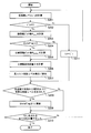
- the adaptive quantizer 1021 performs transmission order (for example, (3, 3) in the case of 4x4 TU) ⁇ (for each orthogonal transform coefficient Kij (0 ⁇ i, j ⁇ 3) ( 3, 2) ⁇ (2, 3) ⁇ (3, 1) ⁇ (2, 2) ⁇ (1, 3) ⁇ (3, 0) ⁇ (2, 1) ⁇ (12) ⁇ (0, 3) ⁇ (2, 0) ⁇ (1, 1) ⁇ (0, 2) ⁇ (1, 0) ⁇ (0, 1) ⁇ (0, 0) in this order):
- step S101 the coefficient level calculation unit 1201 inputs the orthogonal transformation coefficient Kij and the quantization parameter QP using the above equation (1), and outputs the temporary coefficient level L′ ij.
- step S103 the R value calculation unit 1202 receives the temporary coefficient level L′ ij and calculates R value which is the number of value information bits. Then, the process proceeds to step S104.
- step S104 the R position calculation unit 1203 determines whether StateFlag is 0. If StateFlag is 0, the process proceeds to step S105. When StateFlag is 1, the value of R position is set to 0. Then, the process proceeds to step S106.
- step S105 the R position calculation unit 1203 inputs the orthogonal transform coefficient position (i, j) and StateFlag, and calculates R position which is the number of position information bits. Then, the process proceeds to step S106.
- step S106 the high cost coefficient level detection / removal unit 1204 receives L′ ij, R value , and R position , and outputs the coefficient level Lij.
- the high cost coefficient level detection / removal unit 1204 detects L′ ij as the high cost coefficient level when R position is greater than R value , and outputs a value of 0 as Lij. That is, the occurrence of a high cost coefficient level is prevented. Otherwise, the temporary coefficient level L′ ij is output as Lij. Then, the process proceeds to step S107.
- step S107 the state variable update unit 1205 determines whether or not a significant coefficient level has been output from the top to N ( ⁇ 2) in the transmission order in the processing target TU.
- the coefficient level is output by the part that performs quantization in adaptive quantizer 1021.
- the process proceeds to step S108. Otherwise, the process proceeds to step S109.
- step S108 the StateFlag update unit 1205 updates StateFlag to 1. Then, control goes to a step S109.
- step S109 the adaptive quantizer 1021 determines whether or not all orthogonal transform coefficients included in the TU have been quantized. When all the orthogonal transform coefficients are quantized, the TU quantization process ends. Otherwise, the process proceeds to step S101 in order to quantize the next orthogonal transform coefficient.
- the video encoding apparatus of the present embodiment using the adaptive quantizer 1021 described above determines the coefficient level of the orthogonal transform coefficient in consideration of the number of bits of value information and the number of bits of position information (high cost coefficient level). Detection / removal) can prevent the occurrence of a high cost coefficient level.
- the adaptive quantizer 1021 calculates the number of bits of position information of each significant coefficient level by using the coefficient levels up to N ⁇ 2) from the beginning of the TU in the transmission order, so that consecutive N ( ⁇ 2) High cost coefficient level can be detected / removed simultaneously for one provisional coefficient level.
- the video encoding apparatus simultaneously determines a plurality of coefficient levels that are consecutive in the transmission order in consideration of the number of bits of the value information and the number of bits of the position information.
- Parallel quantization processing of orthogonal transform coefficients can be achieved at the same time.
- FIG. 4 (b) is a block diagram showing a configuration example of an adaptive quantizer 1021 that performs parallel processing on orthogonal transform coefficients Kij that are continuous in the transmission order.
- the adaptive quantizer 1021 shown in FIG. 4B includes two coefficient level determination units 110A and 110B, two state variable update units (StateFlag update units) 1205A and 1205B, a distributor 111 and a multiplexer 112.
- StateFlag update units state variable update units
- the distributor 111 receives two orthogonal transform coefficients Kij that are consecutive in the transmission order and their orthogonal transform coefficient positions (i, j) as input, and each orthogonal transform coefficient Kij and orthogonal transform coefficient position (i, j) follow.
- K 33 and K 32 which are consecutive in the transmission order and their orthogonal transform coefficient positions (3, 3) and (3, 2) are input, K 33 and ( 3 and 3) and K 32 and (3, 2) are output to the coefficient level determination unit 110B (the output destination may be reversed). This distribution processing is performed on all orthogonal transform coefficients in the TU in the order of transmission.
- the coefficient level determination units 110A and 110B operate in the same manner as the coefficient level determination unit 110.
- the state variable update unit (StateFlag update unit) 1205A and 1205B operates in the same manner as the state variable update unit (StateFlag update unit) 1205.
- the multiplexer 112 receives the coefficient levels Lij output from the two coefficient level determining units 110A and 110B, rearranges them in the order of transmission, and outputs the two coefficient levels. Specifically, L 33 and L 32 output from the two coefficient level determining units 110A and 110B are input, rearranged in the order of transmission, and output in the order of L 33 and L 32 . This process is performed for all orthogonal transform coefficients in the TU in the order of transmission.
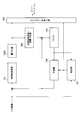
- FIG. FIG. 5 is a block diagram showing a second embodiment of the video encoding apparatus according to the present invention.
- the video encoding apparatus uses the value information bit number, the position information bit number, and the square error reduction amount when detecting the high cost coefficient level.
- the video coding apparatus shown in FIG. 5 has an adaptive quantizer 1021 to which a square error reduction amount calculation unit (D calculation unit) 1206 is added. That is, a square error reduction amount calculation unit 1206 is added in the coefficient level determination unit 110. Further, in the second embodiment, the high cost coefficient level detection / removal unit 1204 of the adaptive quantizer 1021 inputs L′ ij, R value , R position , and the square error reduction amount D 1, and the coefficient level Lij Is output.
- D calculation unit square error reduction amount calculation unit
- the square error reduction amount calculation unit 1206 and the high cost coefficient level detection / removal unit 1204 will be described.
- the square error reduction amount calculation unit 1206 receives the orthogonal transform coefficient Kij, the quantization parameter QP, and L'ij, and outputs a square error reduction amount D.
- the square error reduction amount D is a square error reduction amount with respect to Kij.
- the square error reduction amount calculation unit 1206 calculates D using Kij, Qs, and L'ij as shown in the following equation (3).
- the high cost coefficient level detection / removal unit 1204 inputs L′ ij, R value , R position , and D and outputs the coefficient level Lij.
- the high cost coefficient level detection / removal unit 1204 determines that L'ij is the high cost coefficient level when the product of the sum of R value and R position and ⁇ is equal to or greater than the square error reduction amount D, and 0 The value of is output as Lij. If L'ij is not at a high cost coefficient level, L'ij is output as Lij. Note that ⁇ is the gradient of the relationship between the square error reduction amount and the transmission code amount.
- ⁇ depends on the quantization parameter QP, and becomes smaller as the quantization parameter becomes smaller (as the quantization step size becomes smaller), and becomes larger as the quantization parameter becomes larger (as the quantization step size becomes larger).
- ⁇ is expressed by the following equation (4) using Qs.
- the adaptive quantizer 1021 For each TU, the adaptive quantizer 1021 performs transmission order (for example, (3, 3) in the case of 4x4 TU) ⁇ (for each orthogonal transform coefficient Kij (0 ⁇ i, j ⁇ 3) ( 3, 2) ⁇ (2, 3) ⁇ (3, 1) ⁇ (2, 2) ⁇ (1, 3) ⁇ (3, 0) ⁇ (2, 1) ⁇ (1, 2) ⁇ (0, 3) ⁇ (2, 0) ⁇ (1, 1) ⁇ (0, 2) ⁇ (1, 0) ⁇ (0, 1) ⁇ (0, 0) in this order):
- step S201 the coefficient level calculation unit 1201 inputs the orthogonal transform coefficient Kij and the quantization parameter QP using the above equation (1), and outputs the temporary coefficient level L′ ij.
- step S203 the R value calculation unit 1202 receives the temporary coefficient level L′ ij and calculates R value which is the number of value information bits. Then, the process proceeds to step S204.
- step S204 the R position calculation unit 1203 determines whether StateFlag is 0. If StateFlag is 0, the process proceeds to step S205. When StateFlag is 1, the R position calculation unit 1203 sets the value of R position to 0. Then, control goes to a step S206.
- step S205 the R position calculation unit 1203 inputs the orthogonal transform coefficient position (i, j) and StateFlag, and calculates R position which is the number of position information bits. Then, control goes to a step S206.
- step S206 the square error reduction amount calculation unit 1206 calculates D which is a square error reduction amount for the orthogonal transform coefficient. Then, the process proceeds to step S207.
- step S207 the high-cost coefficient level detection / removal unit 1204 determines that L′ ij is a high-cost coefficient level when the product of ⁇ and the sum of R position and R value is equal to or greater than D. Output the value as Lij. If L′ ij is not at the high cost coefficient level, the high cost coefficient level detection / removal unit 1204 outputs L′ ij as Lij. Then, control goes to a step S208.
- step S208 the state variable update unit 1205 determines whether or not a significant coefficient level has been output from the beginning to N ( ⁇ 2) in the transmission order in the processing target TU. When one or more significant coefficient levels are output, the process proceeds to step S209. Otherwise, the process proceeds to step S210.
- step S209 the StateFlag update unit 1205 updates StateFlag to 1. Then, the process proceeds to step S210.
- step S210 the adaptive quantizer 1021 determines whether all orthogonal transform coefficients included in the TU have been quantized. When all the orthogonal transform coefficients are quantized, the TU quantization process ends. Otherwise, the process proceeds to step S201 to quantize the next orthogonal transform coefficient.
- high cost coefficient level detection / removal is applied to the significant temporary coefficient levels of all values.
- high cost coefficient level detection / removal is applied only to significant temporary coefficient levels of small values (eg, 1 or 2 in absolute value), not to significant temporary coefficient levels of all values. Also good. This is because a significant coefficient level having a small value tends to become a high cost coefficient level.
- image quality deterioration caused by, for example, erroneously setting the coefficient value having a large value to 0 can be suppressed.
- the number of times of applying the high cost coefficient level detection / removal is statistically reduced, so that the quantization processing time can be shortened.
- high cost coefficient level detection / removal is applied to significant temporary coefficient levels of all values in the TU.
- the high cost coefficient level is detected for the remaining significant temporary coefficient levels in the TU.
- / Removal may be applied. By doing so, it is possible to suppress image quality degradation caused by, for example, erroneously setting many small significant coefficient levels to zero.
- the video encoding process is realized by software, the number of times of applying the high cost coefficient level detection / removal is statistically reduced, so that the quantization processing time can be shortened.
- the absolute value sum is easily calculated by the high cost coefficient level detection / removal unit.
- each of the above embodiments can be configured by hardware, it can also be realized by a computer program.
- the information processing system shown in FIG. 7 includes a processor 1001, a program memory 1002, a storage medium 1003 for storing video data, and a storage medium 1004 for storing a bitstream.
- the storage medium 1003 and the storage medium 1004 may be separate storage media, or may be storage areas composed of the same storage medium.
- a magnetic storage medium such as a hard disk can be used as the storage medium.
- the program memory 1002 stores a program for realizing the function of each block shown in FIG. Then, the processor 1001 implements the function of the video encoding device shown in FIG. 1B by executing processing according to the program stored in the program memory 1002.
- FIG. 8 (b) is a block diagram showing the main part of the video encoding apparatus according to the present invention.
- the video encoding apparatus according to the present invention includes an orthogonal transform unit 11 that performs orthogonal transform on an image block to calculate orthogonal transform coefficients, and a quantization unit that quantizes the orthogonal transform coefficients to calculate a coefficient level. 12 and an entropy encoding unit 13 that entropy-encodes the position information of all the significant coefficient levels among the coefficient levels and then entropy-encodes the value information of each significant coefficient level and outputs a bitstream.
- the converting unit 12 is a value information bit number calculation unit that calculates the value information bit number of the significant coefficient level of the orthogonal transform coefficient to be processed in the image block, and quantizes from the beginning to the Nth previous in the transmission order in the image block
- a state variable update unit that monitors a coefficient level output by the unit and updates a state variable indicating whether or not at least one of them is significant; Based on the position of the transform coefficient and the state variable, a position information bit number calculation unit that calculates the number of position information bits of the significant coefficient level of the orthogonal transform coefficient to be processed, the value information bit number and the position information bit number, Includes a high cost coefficient level detection / removal unit that sets a significant coefficient level satisfying a predetermined condition to 0.
- Orthogonal transformation means for orthogonally transforming an image block to calculate orthogonal transformation coefficients
- quantization means for quantizing the orthogonal transformation coefficients to calculate coefficient levels, and all significant coefficient levels among the coefficient levels
- Entropy-encoding means for entropy-encoding the value information of each significant coefficient level and outputting a bitstream after entropy-encoding the position information of each of the significant coefficient levels
- the quantization means includes: Value information bit number calculating means for calculating the value information bit number of the significant coefficient level of the orthogonal transform coefficient to be processed in the image block, and the quantizing means output from the head to N before the transmission order in the image block
- State variable updating means for monitoring the coefficient level and updating a state variable indicating whether at least one of them is significant
- Position information bit number calculating means for calculating the position information bit number of the significant coefficient level of the orthogonal transform coefficient to be processed based on the position of the orthogonal transform coefficient to be processed and the state variable, and the value information
- a video coding apparatus compris
- Orthogonal transformation means for orthogonally transforming an image block to calculate an orthogonal transformation coefficient
- quantization means for quantizing the orthogonal transformation coefficient to calculate a coefficient level, and all significant coefficient levels among the coefficient levels
- Entropy-encoding means for entropy-encoding the value information of each significant coefficient level and outputting a bitstream after entropy-encoding the position information of each of the significant coefficient levels
- the quantization means includes: Value information bit number calculating means for calculating the value information bit number of the significant coefficient level of the orthogonal transform coefficient to be processed in the image block, and the coefficient level output by the quantizing means from the beginning to immediately before in the transmission order in the image block And update a state variable that indicates whether at least one of the previous N-1 coefficient levels is significant
- the number of position information bits for calculating the number of position information bits of the significant coefficient level of the orthogonal transformation coefficient to be processed based on the state variable update means, the position of the orthogonal transformation coefficient to be processed and the state variable
- the said quantization means contains the square error reduction amount calculation means which calculates the square error reduction amount with respect to an orthogonal transformation coefficient using a quantization parameter, the said significant coefficient level, and the said orthogonal transformation coefficient.
- the high cost coefficient level detection / removal means uses the position information bit number, the value information bit number, and the square error reduction amount, so that the square error reduction amount is calculated as follows.
- the video encoding apparatus according to supplementary note 1 or supplementary note 2, wherein a significant coefficient level that is equal to or less than a value obtained by multiplying a sum with a value information bit by a predetermined multiplier is set to 0.
- Orthogonal Transformer 12 Quantizer 13 Entropy Encoder 101 Frequency Converter 1021 Adaptive Quantizer 103 Entropy Encoder 104 Inverse Frequency Transform / Inverse Quantizer 105 Buffer 106 Predictor 107 Estimator 110, 110A, 110B Coefficient Level determination unit 1001 Processor 1002 Program memory 1003 Storage medium 1004 Storage medium 1201 Coefficient level calculation unit 1202 Value information bit number calculation unit (R value calculation unit) 1203 Position information bit number calculation part (R position calculation part) 1204 High cost coefficient level detection / removal unit 1205, 1205A, 1205B State variable update unit (StateFlag update unit) 1206 Square error reduction calculation part (D calculation part)
Landscapes
- Engineering & Computer Science (AREA)
- Multimedia (AREA)
- Signal Processing (AREA)
- Compression Or Coding Systems Of Tv Signals (AREA)
Abstract
Description

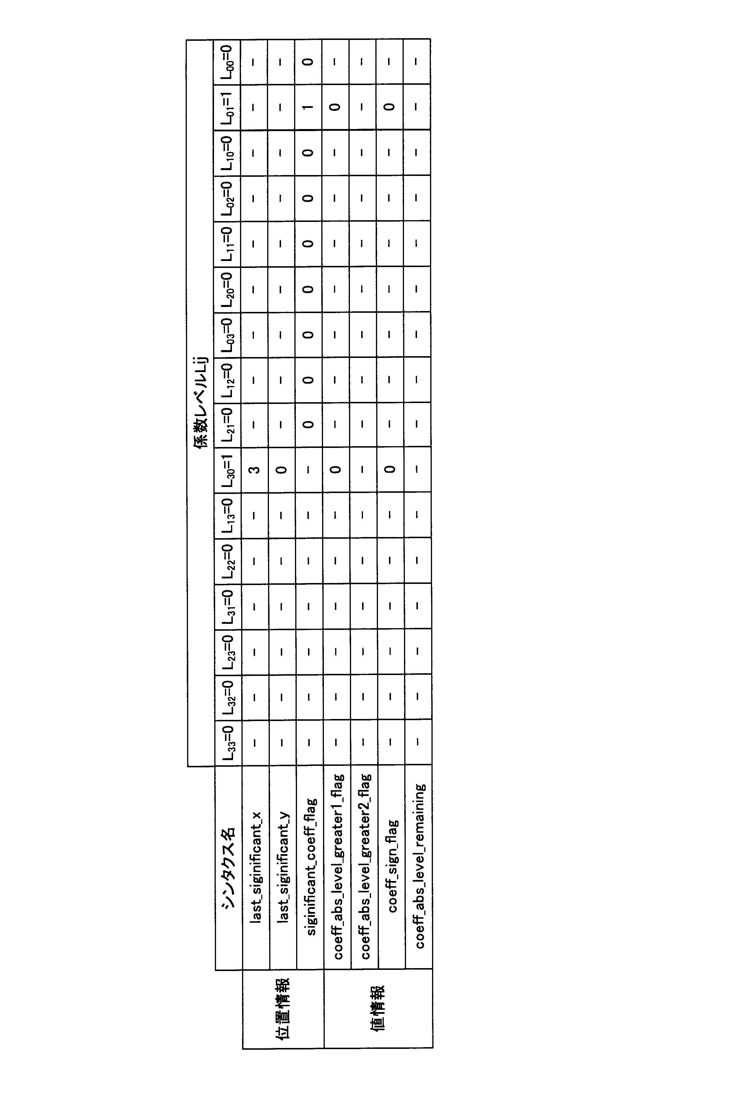

図1 は、本発明による映像符号化装置の第1の実施形態を示すブロック図である。図1 を参照して、ディジタル化された映像の各フレームを入力画像としてビットストリームを出力する第1 の実施形態の映像符号化装置の構成を説明する。
図5 は、本発明による映像符号化装置の第2の実施形態を示すブロック図である。第2の実施形態では、映像符号化装置は、高コスト係数レベルの検出の際に、値情報ビット数、位置情報ビット数、および2乗誤差削減量を用いる。

12 量子化部
13 エントロピー符号化部
101 周波数変換器
1021 適応量子化器
103 エントロピー符号化器
104 逆周波数変換/逆量子化器
105 バッファ
106 予測器
107 推定器
110 ,110A,110B 係数レベル決定部
1001 プロセッサ
1002 プログラムメモリ
1003 記憶媒体
1004 記憶媒体
1201 係数レベル計算部
1202 値情報ビット数計算部(Rvalue計算部)
1203 位置情報ビット数計算部(Rposition 計算部)
1204 高コスト係数レベル検出/除去部
1205,1205A ,1205B 状態変数更新部(StateFlag 更新部)
1206 2乗誤差削減量計算部(D 計算部)
Claims (9)
- 画像ブロックを直交変換して直交変換係数を計算する直交変換手段と、
前記直交変換係数を量子化して係数レベルを計算する量子化手段と、
前記係数レベルのうちすべての有意係数レベルの位置情報をエントロピー符号化した後に、それぞれの前記有意係数レベルの値情報をエントロピー符号化してビットストリームを出力するエントロピー符号化手段とを備える映像符号化装置であって、
前記量子化手段は、
画像ブロックにおいて処理対象とする直交変換係数の有意係数レベルの値情報ビット数を計算する値情報ビット数計算手段と、
画像ブロックにおいて伝送順で先頭からN 個前までに前記量子化手段が出力した係数レベルを監視して、少なくともその一つが有意であるか否かを示す状態変数を更新する状態変数更新手段と、
前記処理対象とする直交変換係数の位置と前記状態変数とに基づいて、前記処理対象とする直交変換係数の有意係数レベルの位置情報ビット数を計算する位置情報ビット数計算手段と、
前記値情報ビット数と前記位置情報ビット数とが所定の条件を満たす有意係数レベルを0にする高コスト係数レベル検出/除去手段とを含む
ことを特徴とする映像符号化装置。 - 前記高コスト係数レベル検出/除去手段は、前記位置情報ビット数が前記値情報ビット数よりも多い場合に、有意係数レベルを0にする
請求項1記載の映像符号化装置。 - 前記量子化手段は、量子化パラメータ、前記有意な係数レベル、および前記直交変換係数を用いて、直交変換係数に対する2乗誤差削減量を計算する2乗誤差削減量計算手段を含み、
前記高コスト係数レベル検出/除去手段は、前記位置情報ビット数、前記値情報ビット数、および前記2乗誤差削減量を用いて、前記2乗誤差削減量が、前記位置情報ビット数と前記値情報ビットとの和に対して所定の乗数を乗じた値以下となる有意係数レベルを0にする
請求項1記載の映像符号化装置。 - 画像ブロックを直交変換して直交変換係数を計算し、
前記直交変換係数を量子化して係数レベルを計算し、
前記係数レベルのうちすべての有意係数レベルの位置情報をエントロピー符号化した後に、それぞれの前記有意係数レベルの値情報をエントロピー符号化してビットストリームを出力する映像符号化方法であって、
前記係数レベルを計算する際に、
画像ブロックにおいて処理対象とする直交変換係数の有意係数レベルの値情報ビット数を計算し、
画像ブロックにおいて伝送順で先頭からN 個前までの係数レベルのうちの少なくとも一つが有意であるか否かを示す状態変数を更新し、
前記処理対象とする直交変換係数の位置と前記状態変数とに基づいて、前記処理対象とする直交変換係数の有意係数レベルの位置情報ビット数を計算し、
前記値情報ビット数と前記位置情報ビット数とが所定の条件を満たす有意係数レベルを0にする
ことを特徴とする映像符号化方法。 - 前記位置情報ビット数が前記値情報ビット数よりも多い場合に、有意係数レベルを0にする
請求項4記載の映像符号化方法。 - 前記係数レベルを計算する際に、量子化パラメータ、前記有意な係数レベル、および前記直交変換係数を用いて、直交変換係数に対する2乗誤差削減量を計算し、
前記位置情報ビット数、前記値情報ビット数、および前記2乗誤差削減量を用いて、前記2乗誤差削減量が、前記位置情報ビット数と前記値情報ビットとの和に対して所定の乗数を乗じた値以下となる有意係数レベルを0にする
請求項4記載の映像符号化方法。 - コンピュータに、
画像ブロックを直交変換して直交変換係数を計算する処理と、
前記直交変換係数を量子化して係数レベルを計算する処理と、
前記係数レベルのうちすべての有意係数レベルの位置情報をエントロピー符号化した後に、それぞれの前記有意係数レベルの値情報をエントロピー符号化してビットストリームを出力する処理とを実行させ、
前記係数レベルを計算する処理で、
画像ブロックにおいて処理対象とする直交変換係数の有意係数レベルの値情報ビット数を計算する処理と、
画像ブロックにおいて伝送順で先頭からN 個前までの係数レベルのうちの少なくとも一つが有意であるか否かを示す状態変数を更新する処理と、
前記処理対象とする直交変換係数の位置と前記状態変数とに基づいて、前記処理対象とする直交変換係数の有意係数レベルの位置情報ビット数を計算する処理と、
前記値情報ビット数と前記位置情報ビット数とが所定の条件を満たす有意係数レベルを0にする処理とを
実行させるための映像符号化プログラム。 - コンピュータに、
前記位置情報ビット数が前記値情報ビット数よりも多い場合に、有意係数レベルを0にする処理を実行させるための請求項7記載の映像符号化プログラム。 - コンピュータに、
前記係数レベルを計算する処理で、量子化パラメータ、前記有意な係数レベル、および前記直交変換係数を用いて、直交変換係数に対する2乗誤差削減量を計算する処理を実行させ、
前記位置情報ビット数、前記値情報ビット数、および前記2乗誤差削減量を用いて、前記2乗誤差削減量が、前記位置情報ビット数と前記値情報ビットとの和に対して所定の乗数を乗じた値以下となる有意係数レベルを0にする処理を実行させる
ための請求項7記載の映像符号化プログラム。
Priority Applications (5)
| Application Number | Priority Date | Filing Date | Title |
|---|---|---|---|
| KR1020157035076A KR101645911B1 (ko) | 2013-06-11 | 2014-04-22 | 영상 부호화 장치, 영상 부호화 방법, 및 영상 부호화 프로그램 |
| US14/888,976 US10045033B2 (en) | 2013-06-11 | 2014-04-22 | Video coding device, video coding method, and video coding program |
| BR112015030096A BR112015030096A2 (pt) | 2013-06-11 | 2014-04-22 | dispositivo de codificação de vídeo, método de codificação de vídeo e programa de codificação de vídeo |
| EP14810729.5A EP3010230A4 (en) | 2013-06-11 | 2014-04-22 | VIDEO CODING DEVICE, VIDEO PROCESSING AND VIDEO PROGRAM |
| JP2014541455A JP5644987B1 (ja) | 2013-06-11 | 2014-04-22 | 映像符号化装置、映像符号化方法および映像符号化プログラム |
Applications Claiming Priority (2)
| Application Number | Priority Date | Filing Date | Title |
|---|---|---|---|
| JP2013-122400 | 2013-06-11 | ||
| JP2013122400 | 2013-06-11 |
Publications (1)
| Publication Number | Publication Date |
|---|---|
| WO2014199551A1 true WO2014199551A1 (ja) | 2014-12-18 |
Family
ID=52021876
Family Applications (1)
| Application Number | Title | Priority Date | Filing Date |
|---|---|---|---|
| PCT/JP2014/002252 WO2014199551A1 (ja) | 2013-06-11 | 2014-04-22 | 映像符号化装置、映像符号化方法および映像符号化プログラム |
Country Status (6)
| Country | Link |
|---|---|
| US (1) | US10045033B2 (ja) |
| EP (1) | EP3010230A4 (ja) |
| JP (1) | JP5644987B1 (ja) |
| KR (1) | KR101645911B1 (ja) |
| BR (1) | BR112015030096A2 (ja) |
| WO (1) | WO2014199551A1 (ja) |
Citations (3)
| Publication number | Priority date | Publication date | Assignee | Title |
|---|---|---|---|---|
| JP2010087771A (ja) * | 2008-09-30 | 2010-04-15 | Nec Electronics Corp | 画像符号化装置及び方法 |
| JP2011509642A (ja) * | 2008-01-08 | 2011-03-24 | クゥアルコム・インコーポレイテッド | Cabacコーダのためのレート歪みモデリングに基づいた量子化 |
| WO2012075193A1 (en) * | 2010-12-03 | 2012-06-07 | Qualcomm Incorporated | Coding the position of a last significant coefficient within a video block based on a scanning order for the block in video coding |
Family Cites Families (2)
| Publication number | Priority date | Publication date | Assignee | Title |
|---|---|---|---|---|
| WO2011080806A1 (ja) * | 2009-12-28 | 2011-07-07 | 富士通株式会社 | 動画像符号化装置および動画像復号装置 |
| US8446301B2 (en) * | 2011-04-15 | 2013-05-21 | Research In Motion Limited | Methods and devices for coding and decoding the position of the last significant coefficient |
-
2014
- 2014-04-22 KR KR1020157035076A patent/KR101645911B1/ko active IP Right Grant
- 2014-04-22 BR BR112015030096A patent/BR112015030096A2/pt not_active IP Right Cessation
- 2014-04-22 WO PCT/JP2014/002252 patent/WO2014199551A1/ja active Application Filing
- 2014-04-22 JP JP2014541455A patent/JP5644987B1/ja not_active Expired - Fee Related
- 2014-04-22 EP EP14810729.5A patent/EP3010230A4/en not_active Withdrawn
- 2014-04-22 US US14/888,976 patent/US10045033B2/en not_active Expired - Fee Related
Patent Citations (3)
| Publication number | Priority date | Publication date | Assignee | Title |
|---|---|---|---|---|
| JP2011509642A (ja) * | 2008-01-08 | 2011-03-24 | クゥアルコム・インコーポレイテッド | Cabacコーダのためのレート歪みモデリングに基づいた量子化 |
| JP2010087771A (ja) * | 2008-09-30 | 2010-04-15 | Nec Electronics Corp | 画像符号化装置及び方法 |
| WO2012075193A1 (en) * | 2010-12-03 | 2012-06-07 | Qualcomm Incorporated | Coding the position of a last significant coefficient within a video block based on a scanning order for the block in video coding |
Non-Patent Citations (4)
| Title |
|---|
| JOINT COLLABORATIVE TEAM ON VIDEO CODING (JCT-VC) OF ITU-T SG16 WP3 AND ISO/IEC JTC1/SC29/WG11 12TH MEETING, 14 January 2013 (2013-01-14) |
| KENTA TOKUMITSU ET AL.: "Entropy Constrained Quantization for Low- Bitrate HEVC Encoding", PROCEEDINGS OF THE 2013 IEICE GENERAL CONFERENCE, JOHO SYSTEM 2, 5 March 2013 (2013-03-05), pages 46, D-11 - 46, XP008181464 * |
| KENTA TOKUMITSU ET AL.: "Entropy Constrained Quantization for Low-Bitrate HEVC Encoding", PROCEEDINGS 2 OF THE IEICE GENERAL CONFERENCE, INFORMATION AND SYSTEMS, March 2013 (2013-03-01) |
| See also references of EP3010230A4 * |
Also Published As
| Publication number | Publication date |
|---|---|
| JP5644987B1 (ja) | 2014-12-24 |
| US20160119630A1 (en) | 2016-04-28 |
| JPWO2014199551A1 (ja) | 2017-02-23 |
| EP3010230A4 (en) | 2016-11-16 |
| US10045033B2 (en) | 2018-08-07 |
| BR112015030096A2 (pt) | 2017-07-25 |
| KR101645911B1 (ko) | 2016-08-04 |
| KR20160006767A (ko) | 2016-01-19 |
| EP3010230A1 (en) | 2016-04-20 |
Similar Documents
| Publication | Publication Date | Title |
|---|---|---|
| JP2022087158A (ja) | イントラ予測方法とそれを利用した符号化器及び復号化器 | |
| US20190075326A1 (en) | Method of Coding and Decoding Images, Coding and Decoding Device and Computer Programs Corresponding Thereto | |
| EP2996337B1 (en) | Method and apparatus for encoding and decoding image by using large transform unit | |
| JP5787116B2 (ja) | ビデオデータのコンテキストモデルを決定する方法及びシステム | |
| CN107483947B (zh) | 视频编码和解码设备及非暂时性计算机可读存储介质 | |
| WO2018123313A1 (ja) | 映像符号化方法、映像復号方法、映像符号化装置、映像復号装置及びプログラム | |
| US7995848B2 (en) | Method and apparatus for encoding and decoding image data | |
| JP2013150323A (ja) | 変換ユニット内の複数サインビット秘匿 | |
| KR20140064972A (ko) | 화상 부호화 및 복호 방법, 장치, 프로그램 | |
| WO2015033510A1 (ja) | 映像符号化装置、映像符号化方法及びプログラム | |
| WO2018123316A1 (ja) | 映像符号化方法、映像復号方法、映像符号化装置、映像復号装置及びプログラム | |
| WO2016194380A1 (ja) | 動画像符号化装置、動画像符号化方法および動画像符号化プログラムを記憶する記録媒体 | |
| JP5574072B1 (ja) | 映像符号化装置、映像符号化方法および映像符号化プログラム | |
| JP6176044B2 (ja) | ブロック構造決定回路および情報圧縮回路 | |
| WO2018123312A1 (ja) | 映像符号化方法、映像復号方法、映像符号化装置、映像復号装置及びプログラム | |
| JP5644987B1 (ja) | 映像符号化装置、映像符号化方法および映像符号化プログラム | |
| JPWO2018123315A1 (ja) | 映像符号化方法、映像復号方法、映像符号化装置、映像復号装置及びプログラム | |
| JP6179606B2 (ja) | 映像符号化装置、映像符号化方法及び映像符号化プログラム | |
| JP6248783B2 (ja) | 動画像符号化装置、動画像符号化方法及び動画像符号化用コンピュータプログラム | |
| WO2015045301A1 (ja) | 映像符号化装置、映像符号化方法および映像符号化プログラム | |
| KR100507441B1 (ko) | 가변장 부호의 입력 특성을 이용한 영상 신호 압축 방법및 상기 방법을 수행하는 비디오 인코더 | |
| KR20170124076A (ko) | 영상 신호 그룹의 부호화 및 복호화 방법과 장치 | |
| KR20040084328A (ko) | 중간 데이터에 기초한 적응적 인트라 매크로블록 갱신 방법 | |
| JP2011223307A (ja) | 画像符号化装置 |
Legal Events
| Date | Code | Title | Description |
|---|---|---|---|
| ENP | Entry into the national phase |
Ref document number: 2014541455 Country of ref document: JP Kind code of ref document: A |
|
| 121 | Ep: the epo has been informed by wipo that ep was designated in this application |
Ref document number: 14810729 Country of ref document: EP Kind code of ref document: A1 |
|
| WWE | Wipo information: entry into national phase |
Ref document number: 2014810729 Country of ref document: EP |
|
| WWE | Wipo information: entry into national phase |
Ref document number: 14888976 Country of ref document: US |
|
| ENP | Entry into the national phase |
Ref document number: 20157035076 Country of ref document: KR Kind code of ref document: A |
|
| NENP | Non-entry into the national phase |
Ref country code: DE |
|
| REG | Reference to national code |
Ref country code: BR Ref legal event code: B01A Ref document number: 112015030096 Country of ref document: BR |
|
| ENP | Entry into the national phase |
Ref document number: 112015030096 Country of ref document: BR Kind code of ref document: A2 Effective date: 20151130 |