WO2014196325A1 - Porphyrin complex and dye-sensitized solar cell - Google Patents
Porphyrin complex and dye-sensitized solar cell Download PDFInfo
- Publication number
- WO2014196325A1 WO2014196325A1 PCT/JP2014/062804 JP2014062804W WO2014196325A1 WO 2014196325 A1 WO2014196325 A1 WO 2014196325A1 JP 2014062804 W JP2014062804 W JP 2014062804W WO 2014196325 A1 WO2014196325 A1 WO 2014196325A1
- Authority
- WO
- WIPO (PCT)
- Prior art keywords
- group
- porphyrin
- ring
- bonded
- substituent
- Prior art date
Links
- 0 Cc(cc1)ccc1N(c1ccc(C)cc1)C1=C(C=C2)N=C2C(N(c2ccc(C)cc2)c2ccc(C)cc2)=C2N3[Zn+](C)(C)[n]4c1ccc4C(c1c(c(C4=C5)ccc6)c6c(*)cc1)=C4[N+]=C5C(C#Cc(cc1)ccc1C(O)=O)=C3C=C2 Chemical compound Cc(cc1)ccc1N(c1ccc(C)cc1)C1=C(C=C2)N=C2C(N(c2ccc(C)cc2)c2ccc(C)cc2)=C2N3[Zn+](C)(C)[n]4c1ccc4C(c1c(c(C4=C5)ccc6)c6c(*)cc1)=C4[N+]=C5C(C#Cc(cc1)ccc1C(O)=O)=C3C=C2 0.000 description 1
Images


Classifications
-
- C—CHEMISTRY; METALLURGY
- C09—DYES; PAINTS; POLISHES; NATURAL RESINS; ADHESIVES; COMPOSITIONS NOT OTHERWISE PROVIDED FOR; APPLICATIONS OF MATERIALS NOT OTHERWISE PROVIDED FOR
- C09B—ORGANIC DYES OR CLOSELY-RELATED COMPOUNDS FOR PRODUCING DYES, e.g. PIGMENTS; MORDANTS; LAKES
- C09B47/00—Porphines; Azaporphines
-
- H—ELECTRICITY
- H01—ELECTRIC ELEMENTS
- H01G—CAPACITORS; CAPACITORS, RECTIFIERS, DETECTORS, SWITCHING DEVICES OR LIGHT-SENSITIVE DEVICES, OF THE ELECTROLYTIC TYPE
- H01G9/00—Electrolytic capacitors, rectifiers, detectors, switching devices, light-sensitive or temperature-sensitive devices; Processes of their manufacture
- H01G9/20—Light-sensitive devices
- H01G9/2059—Light-sensitive devices comprising an organic dye as the active light absorbing material, e.g. adsorbed on an electrode or dissolved in solution
-
- H—ELECTRICITY
- H10—SEMICONDUCTOR DEVICES; ELECTRIC SOLID-STATE DEVICES NOT OTHERWISE PROVIDED FOR
- H10K—ORGANIC ELECTRIC SOLID-STATE DEVICES
- H10K85/00—Organic materials used in the body or electrodes of devices covered by this subclass
- H10K85/30—Coordination compounds
- H10K85/381—Metal complexes comprising a group IIB metal element, e.g. comprising cadmium, mercury or zinc
-
- Y—GENERAL TAGGING OF NEW TECHNOLOGICAL DEVELOPMENTS; GENERAL TAGGING OF CROSS-SECTIONAL TECHNOLOGIES SPANNING OVER SEVERAL SECTIONS OF THE IPC; TECHNICAL SUBJECTS COVERED BY FORMER USPC CROSS-REFERENCE ART COLLECTIONS [XRACs] AND DIGESTS
- Y02—TECHNOLOGIES OR APPLICATIONS FOR MITIGATION OR ADAPTATION AGAINST CLIMATE CHANGE
- Y02E—REDUCTION OF GREENHOUSE GAS [GHG] EMISSIONS, RELATED TO ENERGY GENERATION, TRANSMISSION OR DISTRIBUTION
- Y02E10/00—Energy generation through renewable energy sources
- Y02E10/50—Photovoltaic [PV] energy
- Y02E10/542—Dye sensitized solar cells
-
- Y—GENERAL TAGGING OF NEW TECHNOLOGICAL DEVELOPMENTS; GENERAL TAGGING OF CROSS-SECTIONAL TECHNOLOGIES SPANNING OVER SEVERAL SECTIONS OF THE IPC; TECHNICAL SUBJECTS COVERED BY FORMER USPC CROSS-REFERENCE ART COLLECTIONS [XRACs] AND DIGESTS
- Y02—TECHNOLOGIES OR APPLICATIONS FOR MITIGATION OR ADAPTATION AGAINST CLIMATE CHANGE
- Y02E—REDUCTION OF GREENHOUSE GAS [GHG] EMISSIONS, RELATED TO ENERGY GENERATION, TRANSMISSION OR DISTRIBUTION
- Y02E10/00—Energy generation through renewable energy sources
- Y02E10/50—Photovoltaic [PV] energy
- Y02E10/549—Organic PV cells
Definitions
- the present invention relates to a porphyrin complex comprising a metal atom and a porphyrin derivative, and a dye-sensitized solar cell using the same.
- Porphyrin is a compound that has utility as a sensitizing dye in terms of ease of molecular design, a large extinction coefficient, and possibility of inexpensive synthesis. Therefore, in a dye-sensitized solar cell using a porphyrin complex containing a porphyrin derivative as a sensitizing dye, research for optimizing the molecular structure of the porphyrin derivative has been promoted with the aim of improving the light collecting property. For example, in US Patent Application Publication No.
- Patent Document 1 when a diarylamino group is introduced into another meso position of a porphyrin ring in which at least one of four meso positions is substituted with a carboxyaryl group The influence of the number of substituents and the position of substitution on battery characteristics has been studied.
- Patent Document 1 Fig. 1, Fig. 2, etc. show that the light collecting properties can be improved by increasing the number of diarylamino groups introduced into the meso position. Further, it has been shown that when two diarylamino groups are introduced at the meso position, the light condensing characteristic can be improved by using the trans type as compared with the cis type or bis type. On the other hand, when focusing on the overall battery characteristics based on energy conversion efficiency, short-circuit current density, open-circuit voltage, etc., the case where only one diarylamino group is introduced at the meso position is superior. It has been shown to have properties (Fig.5 to Fig.10, TABLE 1, etc.).
- a push-pull type molecule is introduced by introducing a substituent having a high electron-withdrawing property into the porphyrin ring as an adsorbing group for the electrode material and introducing a plurality of electron-donating groups into the porphyrin ring. It turned out that the charge mobility of a molecule
- the molecular structure of the porphyrin complex is symmetric, for example, when two electron donating groups are introduced so as to be in the trans type, the electron density at the molecular axis containing the electron-withdrawing adsorbing group was found to be extremely low.
- a characteristic configuration of a porphyrin complex comprising a metal atom and a porphyrin derivative coordinated to the metal atom is as follows:
- the porphyrin derivative has one adsorbing group bonded to the porphyrin ring and at least two electron donating groups bonded to the porphyrin ring in a state of forming a ⁇ -conjugated system with the porphyrin ring,
- the adsorptive group is an arylethynyl group substituted with an adsorptive and electron-withdrawing functional group (the aryl ring may further have a substituent), At least two of the electron donating groups are bonded to the porphyrin ring in an asymmetric positional relationship with respect to the arylethynyl group.
- the ⁇ -conjugated system mainly composed of porphyrin can be expanded asymmetrically. Therefore, the electron density in the molecular axis containing the arylethynyl group can be increased.
- the arylethynyl group itself has a triple bond, and this triple bond is conjugated with the ⁇ electron of the porphyrin ring to further expand the ⁇ conjugated system, which can further improve the light collecting property. it can.
- the aryl ethynyl group is bonded to one of the four meso positions of the porphyrin ring, and the two electron donating groups are bonded to the meso position to which the aryl ethynyl group is bonded. It is preferable that they are respectively bonded to adjacent meso positions and opposite meso positions.
- a porphyrin complex capable of effectively improving battery characteristics can be synthesized by a relatively simple synthesis route.
- the electron donating group is preferably a diarylamino group (the aryl ring may have a substituent).
- the charge mobility of the molecule can be effectively enhanced by using a diarylamino group which is stable and has a high electron donating property. Therefore, the electron injection efficiency with respect to the electrode material can be effectively improved, and the battery characteristics can be effectively improved.
- the porphyrin complex of the present invention is specifically represented by the following general formula as a preferred embodiment thereof.
- A represents an arylene group which may have a substituent
- X represents a carboxyl group, a hydroxyl group, a sulfone group, a phosphoric acid group, or a phosphonic acid group
- k is an integer of 5 or less.
- Er1 and Er2 are the same or different and represent an electron-donating group capable of forming a ⁇ -conjugated system with a porphyrin ring
- Ar1 represents an aryl group which may have a substituent
- R1 to R8 Are the same or different and each represents a hydrogen atom, an alkyl group which may have a substituent, an aryl group which may have a substituent, or a halogen atom
- Ar1 and at least one of R6 and R7 are A condensed ring may be formed between them
- M represents a metal atom.
- the characteristic configuration of the dye-sensitized solar cell according to the present invention includes a first electrode having a porous layer formed by adsorbing the porphyrin complex described above as a sensitizing dye on metal oxide particles, and the porous layer sandwiched between the first electrode and the porous layer. It is in the point provided with the 2nd electrode arrange
- FIG. 5 shows a synthesis procedure of the porphyrin complex (ZnPBAT-o-C8) of Example 2.
- the dye-sensitized solar cell 1 includes a photoelectrode 10 as a first electrode, a counter electrode 20 as a second electrode disposed to face the photoelectrode 10, and a photoelectrode 10 and a counter electrode. 20 and an electrolytic solution 30 sealed between them.
- the photoelectrode 10 has a conductive substrate 12 and a porous layer 14 formed on the surface of the conductive substrate 12.
- the conductive substrate 12 is obtained by forming a transparent conductive layer on a transparent substrate.
- a transparent substrate for the photoelectrode 10 for example, a glass substrate such as a quartz substrate and a plastic substrate such as a polyethylene terephthalate substrate or a polycarbonate substrate can be used.
- the conductive layer can be composed of a transparent conductive film such as tin oxide (SnO2), fluorine-doped tin oxide (FTO), or indium tin oxide (ITO).
- a porous layer 14 is laminated on the conductive layer of the conductive substrate 12.
- the porous layer 14 includes porous metal oxide particles 15 and sensitizing dyes 16 adsorbed on the surface of the metal oxide particles 15.
- the metal oxide constituting the metal oxide particles 15 include oxides of Ti, Sn, Zn, Fe, W, Zr, Hf, Sr, In, Ce, Y, La, V, Nb, or Ta. Is done. Among these, TiO2, SnO2, ZnO, ZrO2, Nb2O5 and Ta2O5 are preferable, and TiO2 can be particularly preferably used.
- the metal oxide particles 15 can be nano-sized to sub-micron sized particles.
- the sensitizing dye 16 has a function of absorbing and exciting light energy and injecting electrons into the metal oxide particles 15.
- the dye-sensitized solar cell according to the present invention is characterized in that a porphyrin complex having a specific molecular structure is used as such a sensitizing dye 16. Details of the porphyrin complex will be described later.
- the counter electrode 20 has a conductive substrate 22 having a conductive layer formed on the substrate.
- the conductive substrate 22 has a conductive layer formed on a substrate.
- the substrate for the counter electrode 20 for example, a glass substrate such as a quartz substrate, a plastic substrate such as a polyethylene terephthalate substrate or a polycarbonate substrate, and a metal substrate such as an aluminum substrate or a stainless steel substrate can be used.
- the conductive layer can be composed of a transparent conductive film such as tin oxide (SnO2), fluorine-doped tin oxide (FTO), or indium tin oxide (ITO).
- the counter electrode 20 may have a catalyst layer made of, for example, platinum or carbon.
- the photoelectrode 10 and the counter electrode 20 are arranged to face each other with the porous layer 14 in between. In addition, they are arranged so that the porous layer 14 laminated on the conductive layer on the surface of the photoelectrode 10 and the conductive layer on the surface of the counter electrode 20 face each other with a gap. For this reason, a spacer (not shown) is provided between the photoelectrode 10 and the counter electrode 20.
- the spacer can be configured using a plastic material such as a polyolefin resin such as polyethylene or polypropylene.
- the spacer is formed, for example, in the shape of a rectangular frame and is provided at the peripheral edge of the photoelectrode 10 and the counter electrode 20, and defines a space between the two electrodes and forms a sealed closed space between the two electrodes.
- An electrolytic solution 30 is sealed in a closed space between the photoelectrode 10, the counter electrode 20, and the spacer.
- the electrolytic solution 30 has a function of transporting electrons from the counter electrode 20 to the photoelectrode 10.
- the electrolytic solution 30 is not particularly limited as long as it contains ions capable of donating electrons to the sensitizing dye 16 that has performed electron injection into the metal oxide particles 15 in the porous layer 14.
- Examples of the electrolyte 30 include an iodine-based electrolyte containing I ⁇ / I3 ⁇ , a bromine-based electrolyte including Br ⁇ / Br3 ⁇ , a cobalt-based electrolyte including Co2 + / Co3 +, and a quinone forming a redox pair.
- / Quinone type electrolyte containing hydroquinone can be used. These can be used in a state in which the electrolyte is dissolved in a nonaqueous solvent (such as single or mixed solvent) such as acetonitrile, propylene carbonate, and ethylene carbonate.
- a nonaqueous solvent such as single or mixed solvent
- acetonitrile, propylene carbonate, and ethylene carbonate such as acetonitrile, propylene carbonate, and ethylene carbonate.
- the photoelectrode 10 When light such as sunlight or room light is incident on the photoelectrode 10, the incident light is hardly absorbed and passes through the conductive substrate 12, and most of the light reaches the porous layer 14. When the incident light reaching the porous layer 14 is irradiated to the sensitizing dye 16, the sensitizing dye 16 absorbs light energy and is excited. When the energy level of the sensitizing dye 16 becomes higher than the conduction band of the metal oxide constituting the metal oxide particle 15 by this excitation by a predetermined level or more, electrons are injected from the sensitizing dye 16 into the metal oxide particle 15. Is done. The injected electrons are collected by the photoelectrode 10.
- ions in the electrolytic solution 30 surrounding the periphery of the sensitizing dye 16 that has injected electrons into the metal oxide particles 15 donate electrons.
- the oxidized ions are reduced by receiving electrons from the counter electrode 20.
- ions in the electrolytic solution 30 repeat a redox reaction between the sensitizing dye 16 and the counter electrode 20, thereby generating a potential gradient between the photoelectrode 10 and the counter electrode 20.
- porphyrin complex having a specific molecular structure (hereinafter referred to as “the present porphyrin complex”) used as the sensitizing dye 16 in the present invention
- This porphyrin complex is a complex composed of a metal atom and a porphyrin derivative having a specific molecular structure coordinated to the metal atom.
- Porphyrin is a macrocyclic compound in which four pyrrole rings and four methine groups are alternately bonded (each pyrrole ring is bonded at the ⁇ -position).
- the porphyrin derivative represents a derivative of this porphyrin.
- the metal atom (central metal atom) constituting the porphyrin complex is not particularly limited as long as it can coordinate to the porphyrin ring.
- a metal having excellent stability when coordinated to the porphyrin ring In view of sustainability and cost, it is preferable to use an inexpensive metal with few resource restrictions.
- metal atoms that satisfy these requirements include Zn, Cu, Ti, Ni, Fe, and Mg. Among these, Zn, Cu, Fe, and Mg are preferable, and Zn is particularly preferable.
- the porphyrin derivative constituting the porphyrin complex has one adsorbing group bonded to the porphyrin ring and at least two electron donating groups bonded to the porphyrin ring.
- the adsorbing group has an adsorptive functional group for adsorbing (chemical adsorption) on the surface of the metal oxide particle 15.
- the adsorbing group is designed so as to have an electron withdrawing property as a whole.
- an arylethynyl group hereinafter referred to as “adsorbing arylethynyl group” substituted with at least one adsorptive and electron-withdrawing functional group is used in the present invention.
- the aryl ring may further have a substituent.
- the adsorptive and electron-withdrawing functional group examples include a carboxyl group, a hydroxyl group, a sulfone group, a phosphoric acid group, and a phosphonic acid group.
- a phosphonic acid group When a phosphonic acid group is used, one hydroxyl group may be substituted with an alkyl group or an aryl group (the aryl ring may have a substituent).
- the “phosphonic acid group” is a concept including such an alkyl group-substituted or aryl group-substituted phosphonic acid group.
- a carboxyl group is preferable.
- the number of adsorptive and electron-withdrawing functional groups is preferably one or two.
- a monocarboxyaryl ethynyl group or a dicarboxyaryl ethynyl group is most preferable as the adsorptive group.
- the adsorptive arylethynyl group as the adsorptive group is bonded to the meso position or ⁇ position of the porphyrin ring in a state of forming a ⁇ -conjugated system with the porphyrin ring.
- a ⁇ -conjugated system is a state in which a plurality of carbon atoms are bonded by alternately repeating single bonds and multiple bonds, and ⁇ electrons (electrons on p orbitals) are conjugated to each other and delocalized throughout the molecule. Represents the system that has become.
- a plurality of electron donating groups are also bonded to the meso position or ⁇ position of the porphyrin ring in a state of forming a ⁇ -conjugated system with the porphyrin ring.
- a plurality of electron donating groups are bonded to the porphyrin ring in an asymmetric positional relationship with respect to the adsorptive arylethynyl group.
- the plurality of electron donating groups are bonded to the porphyrin ring so that the molecular structure of the porphyrin complex is asymmetric. That is, a plurality of electron donating groups are respectively bonded to positions of porphyrin rings that are asymmetric with respect to the molecular axis including the adsorbing arylethynyl group in the porphyrin complex.
- the porphyrin complex has a structure in which one adsorbing arylethynyl group and two electron donating groups are asymmetrically bonded to any three of the four meso positions of the porphyrin ring.
- the adsorptive arylethynyl group is bonded to one of the four meso positions of the porphyrin ring, and the two electron donating groups are adjacent to the meso position to which the adsorptive arylethynyl group is bonded. It has a structure bonded to the position and the opposite meso position.
- This porphyrin complex can be represented by the following formula (1).
- A represents an arylene group which may have a substituent.
- X represents an adsorptive functional group, and specifically represents a carboxyl group, a hydroxyl group, a sulfone group, a phosphoric acid group, or a phosphonic acid group.
- k represents an integer of 5 or less.
- Er1 and Er2 are the same or different and represent an electron donating group capable of forming a ⁇ -conjugated system with a porphyrin ring.
- Ar1 represents an aryl group which may have a substituent.
- R1 to R8 are the same or different and each represents a hydrogen atom, an alkyl group which may have a substituent, an aryl group which may have a substituent, or a halogen atom.
- Ar1 and at least one of R6 and R7 may form a condensed ring between them.
- M represents a metal atom.
- Er1 and Er2 examples include a diarylamino group (the aryl ring may have a substituent) and a dialkylaminoarylethynyl group (the aryl ring may further have a substituent).
- the aryl ring may further have a substituent.
- two aryl groups may form a condensed ring between them.
- Er1 and Er2 may be the same or different from each other, but preferably Er1 and Er2 are each a diarylamino group (the aryl ring may have a substituent).
- This porphyrin complex can be specifically represented by the following formula (2) or formula (3) as one embodiment.
- A, X, k, Ar1, R1 to R8, and M have the same definitions as in the formula (1).
- Ar2 to Ar5 are the same or different and each represents an aryl group which may have a substituent.
- R11 to R14 are the same or different and each represents a hydrogen atom, an alkyl group which may have a substituent, or an aryl group which may have a substituent.
- examples of the arylene group represented by A include a phenylene group and a naphthylene group.
- Examples of the aryl group represented by Ar1 to Ar5 and the aryl groups represented by R1 to R8 and R11 to R14 include a phenyl group, a naphthyl group, and an anthryl group.
- Examples of the alkyl group represented by R1 to R8 and R11 to R14 include a linear alkyl group, a branched alkyl group, or a cyclic alkyl group having 1 to 20 carbon atoms.
- halogen atom represented by R1 to R8 and R11 to R14 include a fluorine atom, a chlorine atom, a bromine atom, and an iodine atom.
- the arylene group represented by A may have a substituent
- the aryl group represented by Ar1 to Ar5 may have a substituent
- R1 to R8 Examples of the substituent that the alkyl group or aryl group represented by R11 to R14 may have include a lower alkyl group, a halogen atom, a hydroxyl group, a nitro group, an amino group, a mono-lower alkylamino group, and a di-lower alkylamino.
- Preferable examples of the arylene group represented by A include a phenylene group.
- Preferable examples of the adsorptive functional group represented by X include a carboxyl group.
- Preferable examples of the aryl group represented by Ar1 include a phenyl group, a naphthyl group, and an anthryl group.
- Preferable examples of the aryl group represented by Ar2 to Ar5 include a phenyl group.
- Preferable examples of R1 to R8 include a hydrogen atom or a halogen atom.
- Preferable examples of R11 to R14 include alkyl groups such as methyl group and ethyl group, or alkoxy groups.
- Preferred examples of the phenylene group as a representative example of A include an unsubstituted phenylene group in addition to the ethynyl group and the carboxyl group.
- Preferable examples of the substituent that the phenyl group, naphthyl group, or anthryl group as a representative example of Ar1 may have include an alkyl group such as a methyl group and a t-butyl group, and an alkoxy group such as an octyloxy group. Can be mentioned.
- Preferable examples of the substituent that the phenyl group as a typical example of Ar2 to Ar5 may have include an alkyl group such as a methyl group or a hexyl group.
- Ar1 and R6 may cooperate with each other to form a condensed ring between them.
- Ar1 and R7 may cooperate with each other to form a condensed ring between them.
- Ar1 and both R6 and R7 may cooperate with each other to form a condensed ring between them.
- Er1 and Er2 are diarylamino groups
- Ar2 and Ar3 and / or Ar4 and Ar5 cooperate with each other to form a condensed ring between them. Also good.
- k representing the number of adsorptive functional groups
- the one adsorptive functional group is preferably bonded to the p-position or m-position with respect to the bonding position with the ethynyl group in the aryl ring, Is most preferred.
- the two adsorptive functional groups are bonded to two m-positions or p-position and m-position, respectively, with respect to the bonding position with the ethynyl group in the aryl ring. It is preferable.
- the adsorptive power can be increased as compared with the case of only one adsorptive functional group, and the durability of the dye-sensitized solar cell can be improved.
- the porphyrin complex can be represented by any of the following formulas (4) to (12) as a preferred embodiment.
- the porphyrin complex has an adsorbing arylethynyl group and at least two electron donating groups that are not limited to the four meso positions of the porphyrin ring. It has a structure bonded to any three or more of the meso-position and ⁇ -position. For example, it has a structure in which one adsorptive arylethynyl group is bonded to the ⁇ -position of the porphyrin ring and two to four electron-donating groups are bonded to any one of four meso positions of the porphyrin ring. . Two or three electron donating groups may be bonded in any combination to the four meso positions, but from the viewpoint of the stability of the molecular structure, they are bonded so as to reduce steric hindrance. It is preferable.
- an adsorbing arylethynyl group is bonded to one of the ⁇ positions of the porphyrin ring, and two electron donating groups are bonded to a pyrrole ring bonded to the adsorbing arylethynyl group. It has a structure bonded to two meso positions adjacent to both sides of the opposing pyrrole ring.
- the adsorptive aryl ethynyl group is bonded to one of the ⁇ positions of the porphyrin ring, and three electron donating groups are adjacent to both sides of the pyrrole ring facing the pyrrole ring to which the adsorptive aryl ethynyl group is bonded.
- the adsorptive arylethynyl group is bonded to one of the ⁇ positions of the porphyrin ring, and four electron donating groups are bonded to the four meso positions.
- the porphyrin complex can be represented by the following formulas (13) to (15) as one embodiment.
- A, X, k, Er1, Er2, Ar1, R1 to R5, R7, R8, and M have the same definitions as in the formula (1).
- Ar6 represents an aryl group which may have a substituent.
- Er3 and Er4 are the same or different and represent an electron donating group capable of forming a ⁇ -conjugated system with a porphyrin ring.
- Ar1 and R7 may form a condensed ring between them.
- This porphyrin complex has, as another embodiment, a structure in which one adsorbing arylethynyl group and at least two diarylamino groups are bound to a porphyrin ring without being limited to an asymmetric structure.
- the porphyrin derivative constituting the porphyrin complex has one adsorptive aryl ethynyl group bonded to the porphyrin ring (the aryl ring may further have a substituent) and at least two bonded to the porphyrin ring.
- a diarylamino group the aryl ring may have a substituent).
- the adsorptive aryl ethynyl group is bonded to one of the four meso positions of the porphyrin ring, and at least two diarylamino groups are bonded to the meso-bonded aryl ethynyl group. It is preferable that the bond is bonded to the meso positions adjacent to both sides of the position.
- A, X, k, Ar1 to Ar5, R1 to R8, and M have the same definitions as in the formula (2).
- Ar6 and Ar7 are the same or different and each represents an aryl group which may have a substituent.
- porphyrin complex can be synthesized according to the following procedure. That is, the method for producing the porphyrin complex includes the following steps.
- “porphyrin derivative” means a state in which the porphyrin derivative forms a complex with a metal atom and a free state in which no complex is formed, depending on the situation at each stage. The concept includes both.
- First stage A porphyrin derivative in which one of four meso positions is substituted with an aryl group which may have a substituent is prepared.
- Second stage cis of a porphyrin derivative substituted with an aryl group which may have a substituent and a halogen atom by halogenating one of the other meso positions of the porphyrin derivative obtained in the first stage.
- a mixture of body and trans form is obtained.
- Third stage The cis isomer is separated from the mixture of the cis isomer and the trans isomer obtained in the second stage.
- Fourth stage The halogen atom in the cis isomer obtained in the third stage is substituted with an ethynyl group whose terminal side is protected with a protecting group.
- the remaining two meso positions of the porphyrin derivative obtained in the fourth stage are halogenated.
- Sixth stage Two halogen atoms in the porphyrin derivative obtained in the fifth stage are each substituted with an electron donating group capable of forming a ⁇ -conjugated system together with the porphyrin ring.
- Seventh step After deprotecting the ethynyl group in the porphyrin derivative obtained in the sixth step, an aryl group substituted with an adsorptive and electron-withdrawing functional group on the terminal side of the ethynyl group (the aryl ring is Furthermore, an optionally substituted group is bonded.
- Example 1 The procedure for 5- (4-carboxyphenylethynyl) -10,15-bis (4-methylphenyl) amino-20- (2,4,6-trimethylphenyl) porphyrinatozinc (II) (ZnPBAT) is shown in FIG. Was synthesized according to
- This cis-type intermediate was dissolved in dichloromethane (50 mL), a saturated methanol solution of zinc acetate (5 mL) was added to the solution, and the mixture was stirred for 3 hours.
- the reaction was terminated by the addition of a saturated aqueous solution of sodium bicarbonate (30 mL), and then the mixture was extracted with dichloromethane.
- the obtained extract was dried over anhydrous sodium sulfate.
- the obtained extract (organic phase) was dried over anhydrous sodium sulfate, and the solvent was removed under reduced pressure.
- the residue was dissolved in 4-iodobenzoic acid (44.0 mg, 0.177 mmol) in a mixed solvent of tetrahydrofuran (10 mL) and triethylamine (1.7 mL). After degassing for 10 minutes, tris (dibenzylideneacetone) dipalladium (Pd2 (dba) 3) (10.0 mg, 0.0109 mmol) and triphenylarsine (22.0 mg, 0.0718 mmol) were further added. The resulting mixed solution was refluxed for 4 hours under argon.
- the present porphyrin complex (ZnPBAT) and the porphyrin complex of the comparative example (YD2, ZnPBA) were evaluated for their abilities as sensitizing dyes. Moreover, the dye-sensitized solar cell which used these as a sensitizing dye was produced, and the battery characteristic was evaluated.
- FIG. 3 shows the light absorption spectrum of each porphyrin complex in the ultraviolet-visible near-infrared region.
- the vertical axis represents the molar extinction coefficient
- the horizontal axis represents the wavelength. From this figure, it can be understood that the light absorption spectrum of ZnPBAT having two diarylamino groups is broader than the light absorption spectrum of YD2 having only one diarylamino group. Moreover, it can be understood that the light absorption spectrum of ZnPBAT has a longer wavelength than the light absorption spectra of YD2 and ZnPBA.
- the peak wavelength of ZnPBAT is 15 nm or more longer than the peak wavelength of YD2, and 30 nm or more compared to the peak wavelength of ZnPBA. It was long. Further, when comparing the integrated values in the absorption band on the long wavelength side, ZnPBAT having an ethynyl group (triple bond) bonded to a porphyrin ring has a higher absorption band than ZnPBA having no such functional group. It can be understood that it is greatly enhanced. These results indicate that ZnPBAT further improved the light collection characteristics in the visible region and the near-infrared region as compared with YD2 and ZnPBA.
- FIG. 4 shows an energy diagram of each porphyrin complex.
- the vertical axis represents the oxidation-reduction potential using a standard hydrogen electrode as a reference electrode
- the upper straight line in each porphyrin complex represents LUMO
- the lower straight line represents HOMO. From this figure, it can be understood that ZnPBAT has an increased HOMO level compared to YD2 having a comparable LUMO level. It can also be seen that ZnPBAT has a lower LUMO level than ZnPBA having a comparable HOMO level.
- ZnPBAT has a reduced HOMO-LUMO gap compared to YD2 and ZnPBA.
- a porous layer made of TiO2 particles was laminated on the surface of FTO glass to prepare a titanium oxide electrode.
- the porous layer is about 8 ⁇ m layer composed of TiO 2 particles having an average particle diameter of 20 nm, about 4 ⁇ m layer composed of TiO 2 particles having an average particle diameter of 30 nm, and about TiO 2 particles having an average particle diameter of 400 nm.
- a three-layer structure consisting of 4 ⁇ m layers was formed.
- the prepared titanium oxide electrode was immersed in a 0.2 mM ethanol solution of each porphyrin complex (ZnPBAT, YD2, ZnPBA) to obtain a dye-modified titanium oxide electrode (photoelectrode) in which each porphyrin complex was adsorbed on the surface of TiO2 particles.
- a counter electrode was prepared by forming a platinum thin film on the surface of the FTO glass. The dye-modified titanium oxide electrode and the counter electrode were opposed to each other through a spacer, and an electrolyte solution was sealed to prepare a dye-sensitized solar cell.
- the electrolyte included 1.0M 1,3-dimethylimidazolium iodide, 0.03M iodine, 0.05M lithium iodide, 0.1M guanidine thiocyanate, and 0.5M 4-t.
- a solution obtained by dissolving an electrolyte composed of butylpyridine in a mixed solvent of acetonitrile and valeronitrile (85:15 by volume) was used.
- ZnPBAT battery YD2 battery
- ZnPBA battery ZnPBA battery
- the battery characteristics were evaluated mainly based on energy conversion efficiency ( ⁇ ), short circuit current density, open circuit voltage, and fill factor.
- FIG. 5 shows the result.
- the vertical axis represents energy conversion efficiency
- the horizontal axis represents immersion time.
- the ZnPBAT battery has completely different changes in the energy conversion efficiency in the initial stage compared to the YD2 battery and the ZnPBA battery. Although this is not clear in detail, it is expected to be a phenomenon based on the difference in the association state of the porphyrin complex on the TiO2 particles.
- FIG. 6 is a graph showing the relationship between the amount of chenodeoxycholic acid added and the energy conversion efficiency.
- the vertical axis represents energy conversion efficiency, and the horizontal axis represents the amount added. From this figure, it was found that the amount of chenodeoxycholic acid added to each porphyrin complex was optimally about 10 equivalents for ZnPBAT, about 2 equivalents for YD2, and about 5 equivalents for ZnPBA.
- FIG. 7 shows the result.
- the vertical axis represents energy conversion efficiency
- the horizontal axis represents aging time.
- the energy conversion efficiency of the ZnPBAT cell reached a maximum value of 10.1% after aging for about 36 hours. This is a value that greatly exceeds the maximum value of 8.3% in the ZnPBA battery (approximately 20% increase), and is also significantly higher than the maximum value of 9.1% in the YD2 battery (approximately 10% increase).
- YD2 batteries 11% energy conversion efficiency was reported in Bessho, T.
- FIG. 8 shows the result.
- the vertical axis represents current
- the horizontal axis represents voltage.
- the short circuit current density (JSC), open circuit voltage (VOC), and fill factor (FF) of each battery were calculated.
- the results are summarized in FIG. 9 together with the maximum energy conversion efficiency.
- the fill factor was almost the same in each battery.
- the open circuit voltage was slightly higher for the YD2 battery, but not so significant.
- the short-circuit current density of the ZnPBAT battery was superior to that of the YD2 battery or ZnPBA battery.
- the short-circuit current density of the ZnPBAT battery was significantly higher than that of the ZnPBA battery (approximately 20% increase), and significantly higher than that of the YD2 battery (approximately 10% increase). From these results, it was confirmed that the ZnPBAT battery was very excellent when focusing on the overall battery characteristics.
- FIG. 10 shows the action spectrum of each battery.
- the vertical axis represents external quantum efficiency (IPCE), and the horizontal axis represents wavelength.
- IPCE external quantum efficiency
- the improvement of the external quantum efficiency in the wavelength region of 650 to 800 nm has a positive correlation with the improvement of the light condensing characteristic of the sensitizing dye ZnPBAT itself. I understand that. That is, in the ZnPBAT battery, it can be understood that the improvement of the light collection characteristic works effectively for the improvement of the battery characteristic.
- the porphyrin complex has an enhanced push-pull type molecular structure, uses an adsorbing group including an arylethynyl group having a triple bond, and a plurality of electron donating groups with respect to the adsorbing group. It is characterized in that it is introduced so as to have lower symmetry. Thereby, the condensing characteristic in the visible region and the near-infrared region can be improved, and when it is used as a sensitizing dye in a dye-sensitized solar cell, the battery characteristic can also be improved effectively. .
- Example 2 5- (4-Carboxyphenylethynyl) -10,15-bis (bis (4-methylphenyl) amino) -20- (2,6-bis (octyloxy) phenyl) porphyrinato zinc (II) (ZnPBAT-o- C8) was synthesized.
- ZnPBAT-o-C8 a porphyrin derivative in which one of four meso positions was substituted with a 2,6-dioctyloxyphenyl group was prepared according to the procedure shown in FIG. From this porphyrin derivative, ZnPBAT-o-C8 was synthesized according to a procedure similar to that in Example 1 thereafter.
- ZnPBAT-o-C8 also has the same current collecting characteristics as ZnPBAT and can improve the battery characteristics like ZnPBAT.
- ZnPBAT-o-C8 can suppress the reverse transfer of electrons to ions and the association between porphyrin complexes at the interface with the electrolytic solution as compared with ZnPBAT.
- Example 3 5- (4-Carboxyphenylethynyl) -10,15-bis (bis (4-methylphenyl) amino) -2,20- (4,5- (1-octyloxynaphthalene)) porphyrinatozinc (II) (ZnPBAT -Fused) was synthesized.
- ZnPBAT-fused a porphyrin derivative in which one of four meso positions was substituted with a 4-octyloxynaphthyl group was prepared according to the procedure shown in FIG. Using this porphyrin derivative, ZnPBAT-fused was synthesized according to a procedure similar to that in Example 1 thereafter.
- ZnPBAT-fused has the same current collecting characteristics as ZnPBAT and can improve the battery characteristics in the same manner as ZnPBAT.
- the present invention can be effectively used as a sensitizing dye for a dye-sensitized solar cell.
Abstract
[Problem] To provide a porphyrin complex that has exceptional light collection characteristics, and that when employed as a sensitizing dye in a dye-sensitized solar cell, is able to improve the cell characteristics. [Solution] The present invention relates to a porphyrin complex comprising metal atoms and a porphyrin derivative. The porphyrin derivative has one attracting group and at least two electron-donating groups, which are bonded to the porphyrin ring. The attracting group is an arylethynyl group substituted with a functional group having attraction and electron-withdrawing properties (the aryl ring may have additional substituent groups). The at least two electron-donating groups are bonded to the porphyrin ring, in an asymmetric positional relationship with respect to the arylethynyl group.
Description
本発明は、金属原子とポルフィリン誘導体とからなるポルフィリン錯体、及びこれを用いた色素増感太陽電池に関する。
The present invention relates to a porphyrin complex comprising a metal atom and a porphyrin derivative, and a dye-sensitized solar cell using the same.
光エネルギーを直接的に電力に変換することができる太陽電池は、再生可能かつクリーンなエネルギー源として注目されている。現在普及している太陽電池は、シリコン太陽電池が主流であるが、増感色素を用いる色素増感太陽電池は、シリコン太陽電池と比較してコスト、製造性、意匠性等に優れている。このため、この色素増感太陽電池に関する研究開発が精力的に行われている。色素増感太陽電池の中では、ルテニウム錯体からなる増感色素を含むものを用いることで、10%を超えるエネルギー変換効率を達成し得ることが知られている。しかし、ルテニウムは高価かつ希少な金属であるため、製造コストが比較的高くなりがちであり、また、資源的な制約も受ける。このため、より安価で資源的な制約の少ない増感色素の開発が望まれている。
Solar cells that can directly convert light energy into electric power are attracting attention as a renewable and clean energy source. Silicon solar cells are the mainstream of currently popular solar cells, but dye-sensitized solar cells using sensitizing dyes are superior in cost, manufacturability, design, and the like as compared to silicon solar cells. For this reason, research and development on this dye-sensitized solar cell has been vigorously conducted. Among dye-sensitized solar cells, it is known that energy conversion efficiency exceeding 10% can be achieved by using a sensitizing dye comprising a ruthenium complex. However, since ruthenium is an expensive and rare metal, the production cost tends to be relatively high, and there are also resource constraints. Therefore, development of a sensitizing dye that is less expensive and less resource-constrained is desired.
ポルフィリンは、分子設計の容易性や吸光係数の大きさ、安価な合成可能性等の点において、増感色素としての有用性を備えた化合物である。そこで、ポルフィリン誘導体を含むポルフィリン錯体を増感色素として用いる色素増感太陽電池において、集光特性の向上を狙って、ポルフィリン誘導体の分子構造を最適化するための研究が進められている。例えば米国特許出願公開第2013/0042916号明細書(特許文献1)では、4箇所のメソ位の少なくとも1箇所をカルボキシアリール基で置換したポルフィリン環の他のメソ位にジアリールアミノ基を導入した場合の、置換基数及び置換位置が電池特性に与える影響について検討されている。
Porphyrin is a compound that has utility as a sensitizing dye in terms of ease of molecular design, a large extinction coefficient, and possibility of inexpensive synthesis. Therefore, in a dye-sensitized solar cell using a porphyrin complex containing a porphyrin derivative as a sensitizing dye, research for optimizing the molecular structure of the porphyrin derivative has been promoted with the aim of improving the light collecting property. For example, in US Patent Application Publication No. 2013/0042916 (Patent Document 1), when a diarylamino group is introduced into another meso position of a porphyrin ring in which at least one of four meso positions is substituted with a carboxyaryl group The influence of the number of substituents and the position of substitution on battery characteristics has been studied.
特許文献1のFig.1, Fig.2等には、メソ位に導入するジアリールアミノ基の個数を増やすことにより、集光特性を向上させ得ることが示されている。また、メソ位に2つのジアリールアミノ基を導入する場合において、trans型とすることにより、cis型やbis型に比べて集光特性を向上させ得ることが示されている。その一方で、エネルギー変換効率や短絡電流密度、開放電圧等に基づく総合的な電池特性に注目した場合には、メソ位に導入するジアリールアミノ基を1つだけとする場合の方が、優れた特性を有することが示されている(Fig.5~Fig.10,TABLE 1等)。このように、特許文献1の検討を参照すれば、集光特性の向上要因である置換基数の増大が、必ずしも電池特性の向上のために有効には働いていなかったことが分かる。このため、電池特性をさらに向上させ得る余地が残っていた。
Patent Document 1, Fig. 1, Fig. 2, etc. show that the light collecting properties can be improved by increasing the number of diarylamino groups introduced into the meso position. Further, it has been shown that when two diarylamino groups are introduced at the meso position, the light condensing characteristic can be improved by using the trans type as compared with the cis type or bis type. On the other hand, when focusing on the overall battery characteristics based on energy conversion efficiency, short-circuit current density, open-circuit voltage, etc., the case where only one diarylamino group is introduced at the meso position is superior. It has been shown to have properties (Fig.5 to Fig.10, TABLE 1, etc.). Thus, referring to the examination of Patent Document 1, it can be seen that the increase in the number of substituents, which is a factor for improving the light collecting characteristics, did not always work effectively for improving the battery characteristics. For this reason, the room which can improve a battery characteristic further remained.
そこで、集光特性に優れ、さらに色素増感太陽電池における増感色素として用いられる場合に電池特性をも向上させ得る新規なポルフィリン錯体の実現が望まれる。
Therefore, it is desired to realize a novel porphyrin complex that has excellent light collecting properties and can improve battery properties when used as a sensitizing dye in a dye-sensitized solar cell.
本発明者らの検討によれば、電極材料に対する吸着基として電子吸引性の高い置換基をポルフィリン環に導入するとともに複数の電子供与性基をポルフィリン環に導入して、プッシュ・プル型の分子構造とすることで、分子の電荷移動性が高まることが分かった。また、例えば2つの電子供与性基をtrans型となるように導入する場合等のようにポルフィリン錯体の分子構造が対称的である場合には、電子吸引性の吸着基を含む分子軸における電子密度が極めて低くなることを見出した。これらの新規な知見に基づき、ポルフィリン錯体の分子構造をプッシュ・プル型としつつ吸着基を含む分子軸における電子密度を高めることができれば、電池特性を大きく向上させ得るとの予測の下、鋭意研究の結果、本発明が完成された。
According to the study by the present inventors, a push-pull type molecule is introduced by introducing a substituent having a high electron-withdrawing property into the porphyrin ring as an adsorbing group for the electrode material and introducing a plurality of electron-donating groups into the porphyrin ring. It turned out that the charge mobility of a molecule | numerator increases by setting it as a structure. In addition, when the molecular structure of the porphyrin complex is symmetric, for example, when two electron donating groups are introduced so as to be in the trans type, the electron density at the molecular axis containing the electron-withdrawing adsorbing group Was found to be extremely low. Based on these new findings, earnest research with the expectation that if the electron density at the molecular axis containing the adsorbing group can be increased while the molecular structure of the porphyrin complex is made to be a push-pull type, the battery characteristics can be greatly improved. As a result, the present invention was completed.
本発明に係る、金属原子と、この金属原子に配位したポルフィリン誘導体と、からなるポルフィリン錯体の特徴構成は、
前記ポルフィリン誘導体は、ポルフィリン環に結合された1つの吸着基と、前記ポルフィリン環と共にπ共役系を形成する状態で当該ポルフィリン環に結合された少なくとも2つの電子供与性基と、を有し、
前記吸着基は、吸着性かつ電子吸引性の官能基で置換されたアリールエチニル基(アリール環はさらに置換基を有していても良い)であり、
少なくとも2つの前記電子供与性基が、前記アリールエチニル基に対して非対称な位置関係で前記ポルフィリン環に結合している点にある。 According to the present invention, a characteristic configuration of a porphyrin complex comprising a metal atom and a porphyrin derivative coordinated to the metal atom is as follows:
The porphyrin derivative has one adsorbing group bonded to the porphyrin ring and at least two electron donating groups bonded to the porphyrin ring in a state of forming a π-conjugated system with the porphyrin ring,
The adsorptive group is an arylethynyl group substituted with an adsorptive and electron-withdrawing functional group (the aryl ring may further have a substituent),
At least two of the electron donating groups are bonded to the porphyrin ring in an asymmetric positional relationship with respect to the arylethynyl group.
この特徴構成によれば、色素増感太陽電池の電極材料に対する吸着基として吸着性かつ電子吸引性の官能基で置換されたアリールエチニル基を採用することで、これと電子供与性基とによりプッシュ・プル型の分子構造が実現される。よって、分子の電荷移動性を高めることができる。また、電子供与性基の個数を複数とすることで、集光特性を有効に向上させることができる。
According to this characteristic configuration, by adopting an arylethynyl group substituted with an adsorptive and electron-withdrawing functional group as an adsorbing group for the electrode material of the dye-sensitized solar cell, it is pushed by this and the electron-donating group.・ Pull-type molecular structure is realized. Therefore, the charge mobility of the molecule can be improved. In addition, the light collecting property can be effectively improved by using a plurality of electron donating groups.
このとき、複数の電子供与性基をアリールエチニル基に対して非対称な位置関係でポルフィリン環に結合させることで、ポルフィリンを主体とするπ共役系を非対称的に拡張することができる。よって、アリールエチニル基を含む分子軸における電子密度を高めることができる。また、アリールエチニル基は、それ自体、三重結合を有しており、この三重結合はポルフィリン環のπ電子と共役してπ共役系がさらに拡張されるため、集光特性をさらに向上させることができる。また、アリールエチニル基の三重結合部位における電子密度が高まるため、電極材料に対する吸着性及び電子注入効率を有効に向上させることができる。従って、このポルフィリン錯体を色素増感太陽電池における増感色素として用いることで、エネルギー変換効率や耐久性能等の電池特性を有効に向上させることができる。
At this time, by coupling a plurality of electron donating groups to the porphyrin ring in an asymmetric positional relationship with respect to the arylethynyl group, the π-conjugated system mainly composed of porphyrin can be expanded asymmetrically. Therefore, the electron density in the molecular axis containing the arylethynyl group can be increased. In addition, the arylethynyl group itself has a triple bond, and this triple bond is conjugated with the π electron of the porphyrin ring to further expand the π conjugated system, which can further improve the light collecting property. it can. Moreover, since the electron density in the triple bond part of an aryl ethynyl group increases, the adsorptivity with respect to an electrode material and electron injection efficiency can be improved effectively. Therefore, by using this porphyrin complex as a sensitizing dye in a dye-sensitized solar cell, battery characteristics such as energy conversion efficiency and durability can be effectively improved.
以下、本発明の好適な態様について説明する。
Hereinafter, preferred embodiments of the present invention will be described.
1つの態様として、前記アリールエチニル基が、前記ポルフィリン環の4箇所のメソ位の1つに結合しており、2つの前記電子供与性基が、前記アリールエチニル基が結合したメソ位に対して、隣接するメソ位及び対向するメソ位にそれぞれ結合していると好適である。
In one embodiment, the aryl ethynyl group is bonded to one of the four meso positions of the porphyrin ring, and the two electron donating groups are bonded to the meso position to which the aryl ethynyl group is bonded. It is preferable that they are respectively bonded to adjacent meso positions and opposite meso positions.
この構成によれば、電池特性を有効に向上させ得るポルフィリン錯体を、比較的簡単な合成ルートで合成可能とすることができる。
According to this configuration, a porphyrin complex capable of effectively improving battery characteristics can be synthesized by a relatively simple synthesis route.
1つの態様として、前記電子供与性基は、ジアリールアミノ基(アリール環は置換基を有していても良い)であると好適である。
In one embodiment, the electron donating group is preferably a diarylamino group (the aryl ring may have a substituent).
この構成によれば、安定かつ電子供与性の高いジアリールアミノ基を用いることで、分子の電荷移動性を有効に高めることができる。よって、電極材料に対する電子注入効率を有効に向上させることができ、電池特性を有効に向上させることができる。
According to this configuration, the charge mobility of the molecule can be effectively enhanced by using a diarylamino group which is stable and has a high electron donating property. Therefore, the electron injection efficiency with respect to the electrode material can be effectively improved, and the battery characteristics can be effectively improved.
本発明のポルフィリン錯体は、その好適な一態様として、具体的には、下記の一般式で表される。

[式中、Aは、置換基を有していても良いアリーレン基を表し、Xは、カルボキシル基、水酸基、スルホン基、リン酸基、又はホスホン酸基を表し、kは、5以下の整数を表し、Er1,Er2は、同一又は相異なり、ポルフィリン環と共にπ共役系を形成可能な電子供与性基を表し、Ar1は、置換基を有していても良いアリール基を表し、R1~R8は、同一又は相異なり、水素原子、置換基を有していても良いアルキル基、置換基を有していても良いアリール基、又はハロゲン原子を表し、Ar1とR6及びR7の少なくとも一方とは、それらの間で縮合環を形成していても良く、Mは、金属原子を表す。]
The porphyrin complex of the present invention is specifically represented by the following general formula as a preferred embodiment thereof.
[In the formula, A represents an arylene group which may have a substituent, X represents a carboxyl group, a hydroxyl group, a sulfone group, a phosphoric acid group, or a phosphonic acid group, and k is an integer of 5 or less. Er1 and Er2 are the same or different and represent an electron-donating group capable of forming a π-conjugated system with a porphyrin ring, Ar1 represents an aryl group which may have a substituent, R1 to R8 Are the same or different and each represents a hydrogen atom, an alkyl group which may have a substituent, an aryl group which may have a substituent, or a halogen atom, and Ar1 and at least one of R6 and R7 are A condensed ring may be formed between them, and M represents a metal atom. ]
本発明に係る色素増感太陽電池の特徴構成は、上述したポルフィリン錯体を増感色素として金属酸化物の粒子に吸着させてなる多孔質層を有する第一電極と、前記多孔質層を挟んで前記第一電極に対向して配置される第二電極と、前記第一電極と前記第二電極との間に封入される電解液と、を備える点にある。
The characteristic configuration of the dye-sensitized solar cell according to the present invention includes a first electrode having a porous layer formed by adsorbing the porphyrin complex described above as a sensitizing dye on metal oxide particles, and the porous layer sandwiched between the first electrode and the porous layer. It is in the point provided with the 2nd electrode arrange | positioned facing said 1st electrode, and the electrolyte solution enclosed between said 1st electrode and said 2nd electrode.
この特徴構成によれば、エネルギー変換効率や短絡電流密度、開放電圧等の特性に優れた色素増感太陽電池を実現することができる。
According to this characteristic configuration, a dye-sensitized solar cell excellent in characteristics such as energy conversion efficiency, short-circuit current density, and open-circuit voltage can be realized.
本発明に係る色素増感太陽電池及びそれに用いられるポルフィリン錯体の実施形態について、図面を参照して説明する。まず、本実施形態に係る色素増感太陽電池1の全体構成について説明する。図1に示すように、色素増感太陽電池1は、第一電極としての光電極10と、この光電極10に対向して配置される第二電極としての対極20と、光電極10と対極20との間に封入される電解液30とを備えている。
Embodiments of a dye-sensitized solar cell according to the present invention and a porphyrin complex used therein will be described with reference to the drawings. First, the overall configuration of the dye-sensitized solar cell 1 according to this embodiment will be described. As shown in FIG. 1, the dye-sensitized solar cell 1 includes a photoelectrode 10 as a first electrode, a counter electrode 20 as a second electrode disposed to face the photoelectrode 10, and a photoelectrode 10 and a counter electrode. 20 and an electrolytic solution 30 sealed between them.
光電極10は、導電性基板12と、この導電性基板12の表面に形成された多孔質層14とを有する。導電性基板12は、透明基板上に透明な導電層が形成されたものである。光電極10用の透明基板としては、例えば、石英基板等のガラス基板、及びポリエチレンテレフタレート基板やポリカーボネート基板等のプラスチック基板等を用いることができる。導電層は、酸化スズ(SnO2)やフッ素ドープ酸化スズ(FTO)、酸化インジウムスズ(ITO)等の透明性導電膜により構成することができる。
The photoelectrode 10 has a conductive substrate 12 and a porous layer 14 formed on the surface of the conductive substrate 12. The conductive substrate 12 is obtained by forming a transparent conductive layer on a transparent substrate. As the transparent substrate for the photoelectrode 10, for example, a glass substrate such as a quartz substrate and a plastic substrate such as a polyethylene terephthalate substrate or a polycarbonate substrate can be used. The conductive layer can be composed of a transparent conductive film such as tin oxide (SnO2), fluorine-doped tin oxide (FTO), or indium tin oxide (ITO).
導電性基板12の導電層上には、多孔質層14が積層されている。多孔質層14は、ポーラス状に集積された金属酸化物粒子15と、金属酸化物粒子15の表面に吸着した増感色素16とを有する。金属酸化物粒子15を構成する金属酸化物としては、例えばTi、Sn、Zn、Fe、W、Zr、Hf、Sr、In、Ce、Y、La、V、Nb、又はTaの酸化物が例示される。これらの中では、TiO2、SnO2、ZnO、ZrO2、Nb2O5、Ta2O5が好ましく、TiO2を特に好適に用いることができる。金属酸化物粒子15は、ナノサイズ~サブミクロンサイズの粒子とすることができる。増感色素16は、光エネルギーを吸収して励起し、金属酸化物粒子15に電子を注入する機能を有する。本発明に係る色素増感太陽電池は、このような増感色素16として、特定の分子構造を有するポルフィリン錯体を用いる点に特徴を有する。ポルフィリン錯体の詳細については、後述する。
A porous layer 14 is laminated on the conductive layer of the conductive substrate 12. The porous layer 14 includes porous metal oxide particles 15 and sensitizing dyes 16 adsorbed on the surface of the metal oxide particles 15. Examples of the metal oxide constituting the metal oxide particles 15 include oxides of Ti, Sn, Zn, Fe, W, Zr, Hf, Sr, In, Ce, Y, La, V, Nb, or Ta. Is done. Among these, TiO2, SnO2, ZnO, ZrO2, Nb2O5 and Ta2O5 are preferable, and TiO2 can be particularly preferably used. The metal oxide particles 15 can be nano-sized to sub-micron sized particles. The sensitizing dye 16 has a function of absorbing and exciting light energy and injecting electrons into the metal oxide particles 15. The dye-sensitized solar cell according to the present invention is characterized in that a porphyrin complex having a specific molecular structure is used as such a sensitizing dye 16. Details of the porphyrin complex will be described later.
対極20は、基板上に導電層が形成された導電性基板22を有する。導電性基板22は、基板上に導電層が形成されたものである。対極20用の基板としては、例えば、石英基板等のガラス基板、ポリエチレンテレフタレート基板やポリカーボネート基板等のプラスチック基板、及びアルミニウム基板やステンレス基板等の金属基板等を用いることができる。導電層は、光電極10と同様に、酸化スズ(SnO2)やフッ素ドープ酸化スズ(FTO)、酸化インジウムスズ(ITO)等の透明性導電膜により構成することができる。対極20は、例えば白金や炭素等からなる触媒層を有していても良い。
The counter electrode 20 has a conductive substrate 22 having a conductive layer formed on the substrate. The conductive substrate 22 has a conductive layer formed on a substrate. As the substrate for the counter electrode 20, for example, a glass substrate such as a quartz substrate, a plastic substrate such as a polyethylene terephthalate substrate or a polycarbonate substrate, and a metal substrate such as an aluminum substrate or a stainless steel substrate can be used. Similar to the photoelectrode 10, the conductive layer can be composed of a transparent conductive film such as tin oxide (SnO2), fluorine-doped tin oxide (FTO), or indium tin oxide (ITO). The counter electrode 20 may have a catalyst layer made of, for example, platinum or carbon.
光電極10と対極20とは、多孔質層14を挟んで対向して配置されている。また、これらは、光電極10の表面の導電層に積層された多孔質層14と対極20の表面の導電層とが隙間を隔てて対向するように配置されている。このため、光電極10と対極20との間には、スペーサ(図示せず)が設けられている。スペーサは、例えばポリエチレンやポリプロピレン等のポリオレフィン系樹脂等のプラスチック製材料を用いて構成することができる。スペーサは、例えば矩形枠状に形成されて光電極10及び対極20の周縁部に設けられ、両極間の間隔を規定するとともに密閉された閉空間を両極間に形成している。
The photoelectrode 10 and the counter electrode 20 are arranged to face each other with the porous layer 14 in between. In addition, they are arranged so that the porous layer 14 laminated on the conductive layer on the surface of the photoelectrode 10 and the conductive layer on the surface of the counter electrode 20 face each other with a gap. For this reason, a spacer (not shown) is provided between the photoelectrode 10 and the counter electrode 20. The spacer can be configured using a plastic material such as a polyolefin resin such as polyethylene or polypropylene. The spacer is formed, for example, in the shape of a rectangular frame and is provided at the peripheral edge of the photoelectrode 10 and the counter electrode 20, and defines a space between the two electrodes and forms a sealed closed space between the two electrodes.
光電極10と対極20とスペーサとの間の閉空間には、電解液30が封入されている。電解液30は、対極20から光電極10へと電子を輸送する機能を有する。電解液30は、多孔質層14において金属酸化物粒子15に電子注入を果たした増感色素16に電子を供与することができるイオンが含まれているものであれば特に限定されない。電解液30としては、レドックス対を形成する例えばI-/I3-を含むヨウ素系の電解液、Br-/Br3-を含む臭素系の電解液、Co2+/Co3+を含むコバルト系の電解液、キノン/ハイドロキノンを含むキノン系の電解液等を用いることができる。これらは、アセトニトリル、炭酸プロピレン、エチレンカーボネート等の非水溶媒(単独でも良いし、混合溶媒であっても良い)に電解質を溶解させた状態で使用することができる。
An electrolytic solution 30 is sealed in a closed space between the photoelectrode 10, the counter electrode 20, and the spacer. The electrolytic solution 30 has a function of transporting electrons from the counter electrode 20 to the photoelectrode 10. The electrolytic solution 30 is not particularly limited as long as it contains ions capable of donating electrons to the sensitizing dye 16 that has performed electron injection into the metal oxide particles 15 in the porous layer 14. Examples of the electrolyte 30 include an iodine-based electrolyte containing I− / I3−, a bromine-based electrolyte including Br− / Br3−, a cobalt-based electrolyte including Co2 + / Co3 +, and a quinone forming a redox pair. / Quinone type electrolyte containing hydroquinone can be used. These can be used in a state in which the electrolyte is dissolved in a nonaqueous solvent (such as single or mixed solvent) such as acetonitrile, propylene carbonate, and ethylene carbonate.
光電極10に太陽光や室内光等の光が入射すると、この入射光はほとんど吸収されることなく導電性基板12を透過して、大部分が多孔質層14に到達する。そして、多孔質層14に到達した入射光が増感色素16に照射されると、この増感色素16は光エネルギーを吸収して励起する。この励起により、増感色素16のエネルギー準位が金属酸化物粒子15を構成する金属酸化物の伝導帯よりも所定レベル以上高くなると、増感色素16から金属酸化物粒子15へと電子が注入される。注入された電子は、光電極10で集電される。
When light such as sunlight or room light is incident on the photoelectrode 10, the incident light is hardly absorbed and passes through the conductive substrate 12, and most of the light reaches the porous layer 14. When the incident light reaching the porous layer 14 is irradiated to the sensitizing dye 16, the sensitizing dye 16 absorbs light energy and is excited. When the energy level of the sensitizing dye 16 becomes higher than the conduction band of the metal oxide constituting the metal oxide particle 15 by this excitation by a predetermined level or more, electrons are injected from the sensitizing dye 16 into the metal oxide particle 15. Is done. The injected electrons are collected by the photoelectrode 10.
一方、金属酸化物粒子15への電子注入を果たした増感色素16には、その周囲を取り囲んでいる電解液30中のイオンが電子を供与する。その際に酸化されたイオンは、対極20から電子を受け取ることによって還元される。このように、電解液30中のイオンが増感色素16と対極20との間で酸化還元反応を繰り返すことで光電極10と対極20との間に電位勾配が生じるので、両極間に外部負荷40を接続することにより、その外部負荷40に電力を供給することができる。
On the other hand, ions in the electrolytic solution 30 surrounding the periphery of the sensitizing dye 16 that has injected electrons into the metal oxide particles 15 donate electrons. In this case, the oxidized ions are reduced by receiving electrons from the counter electrode 20. In this way, ions in the electrolytic solution 30 repeat a redox reaction between the sensitizing dye 16 and the counter electrode 20, thereby generating a potential gradient between the photoelectrode 10 and the counter electrode 20. By connecting 40, power can be supplied to the external load 40.
次に、本発明において増感色素16として用いられる、特定の分子構造を有するポルフィリン錯体(以下、「本ポルフィリン錯体」と称する)について説明する。本ポルフィリン錯体は、金属原子と、この金属原子に配位した特定の分子構造を有するポルフィリン誘導体とからなる錯体である。なお、ポルフィリンは、4つのピロール環と4つのメチン基とが交互に結合(各ピロール環はα位で結合)した大環状化合物である。ポルフィリン誘導体とは、このポルフィリンの誘導体を表す。
Next, a porphyrin complex having a specific molecular structure (hereinafter referred to as “the present porphyrin complex”) used as the sensitizing dye 16 in the present invention will be described. This porphyrin complex is a complex composed of a metal atom and a porphyrin derivative having a specific molecular structure coordinated to the metal atom. Porphyrin is a macrocyclic compound in which four pyrrole rings and four methine groups are alternately bonded (each pyrrole ring is bonded at the α-position). The porphyrin derivative represents a derivative of this porphyrin.
本ポルフィリン錯体を構成する金属原子(中心金属原子)としては、ポルフィリン環に配位することができるものであれば特に限定されない。但し、色素増感太陽電池1の耐久性能に与える影響を考慮すれば、ポルフィリン環に配位した際の安定性に優れる金属を用いることが好ましい。また、持続可能性やコストの点を考慮すれば、資源的な制約が少なく安価な金属を用いることが好ましい。これらの要求を満足する金属原子としては、例えばZn、Cu、Ti、Ni、Fe、Mgが挙げられる。中でも、Zn、Cu、Fe、Mgが好ましく、Znが特に好ましい。
The metal atom (central metal atom) constituting the porphyrin complex is not particularly limited as long as it can coordinate to the porphyrin ring. However, considering the influence on the durability performance of the dye-sensitized solar cell 1, it is preferable to use a metal having excellent stability when coordinated to the porphyrin ring. In view of sustainability and cost, it is preferable to use an inexpensive metal with few resource restrictions. Examples of metal atoms that satisfy these requirements include Zn, Cu, Ti, Ni, Fe, and Mg. Among these, Zn, Cu, Fe, and Mg are preferable, and Zn is particularly preferable.
本ポルフィリン錯体を構成するポルフィリン誘導体は、ポルフィリン環に結合された1つの吸着基と、ポルフィリン環に結合された少なくとも2つの電子供与性基とを有する。吸着基は、金属酸化物粒子15の表面に吸着(化学吸着)するための吸着性官能基を有する。また、吸着基は、全体として電子吸引性を有するように設計される。このような吸着基として、本発明では、少なくとも1つの吸着性かつ電子吸引性の官能基で置換された、アリールエチニル基(以下、「吸着性アリールエチニル基」と称する)を用いる。なお、アリール環はさらに置換基を有していても良い。
The porphyrin derivative constituting the porphyrin complex has one adsorbing group bonded to the porphyrin ring and at least two electron donating groups bonded to the porphyrin ring. The adsorbing group has an adsorptive functional group for adsorbing (chemical adsorption) on the surface of the metal oxide particle 15. The adsorbing group is designed so as to have an electron withdrawing property as a whole. As such an adsorbing group, an arylethynyl group (hereinafter referred to as “adsorbing arylethynyl group”) substituted with at least one adsorptive and electron-withdrawing functional group is used in the present invention. The aryl ring may further have a substituent.
吸着性かつ電子吸引性の官能基としては、例えばカルボキシル基、水酸基、スルホン基、リン酸基、ホスホン酸基等が例示される。ホスホン酸基を用いる場合には、1つの水酸基がアルキル基又はアリール基(アリール環は置換基を有していても良い)で置換されていても良い。本明細書において、「ホスホン酸基」とは、そのようなアルキル基置換又はアリール基置換のホスホン酸基を含む概念とする。上述した中では、カルボキシル基が好ましい。また、吸着性かつ電子吸引性の官能基の個数は、1つ又は2つが好ましい。すなわち、モノカルボキシアリールエチニル基又はジカルボキシアリールエチニル基が吸着基として最も好ましい。吸着基としての吸着性アリールエチニル基は、ポルフィリン環と共にπ共役系を形成する状態で、ポルフィリン環のメソ位又はβ位に結合している。なお、π共役系とは、複数の炭素原子が単結合と多重結合とを交互に繰り返して結合された状態で、π電子(p軌道上の電子)が互いに共役して分子全体に非局在化している系を表す。
Examples of the adsorptive and electron-withdrawing functional group include a carboxyl group, a hydroxyl group, a sulfone group, a phosphoric acid group, and a phosphonic acid group. When a phosphonic acid group is used, one hydroxyl group may be substituted with an alkyl group or an aryl group (the aryl ring may have a substituent). In the present specification, the “phosphonic acid group” is a concept including such an alkyl group-substituted or aryl group-substituted phosphonic acid group. Among the above, a carboxyl group is preferable. Further, the number of adsorptive and electron-withdrawing functional groups is preferably one or two. That is, a monocarboxyaryl ethynyl group or a dicarboxyaryl ethynyl group is most preferable as the adsorptive group. The adsorptive arylethynyl group as the adsorptive group is bonded to the meso position or β position of the porphyrin ring in a state of forming a π-conjugated system with the porphyrin ring. A π-conjugated system is a state in which a plurality of carbon atoms are bonded by alternately repeating single bonds and multiple bonds, and π electrons (electrons on p orbitals) are conjugated to each other and delocalized throughout the molecule. Represents the system that has become.
複数の電子供与性基も、ポルフィリン環と共にπ共役系を形成する状態で、ポルフィリン環のメソ位又はβ位に結合している。本発明では、複数の電子供与性基は、吸着性アリールエチニル基に対して非対称な位置関係でポルフィリン環に結合している。言い換えれば、複数の電子供与性基は、ポルフィリン錯体の分子構造が非対称的となるようにポルフィリン環に結合している。すなわち、複数の電子供与性基は、ポルフィリン錯体における吸着性アリールエチニル基を含む分子軸に対して互いに非対称となるポルフィリン環の位置に、それぞれ結合している。
A plurality of electron donating groups are also bonded to the meso position or β position of the porphyrin ring in a state of forming a π-conjugated system with the porphyrin ring. In the present invention, a plurality of electron donating groups are bonded to the porphyrin ring in an asymmetric positional relationship with respect to the adsorptive arylethynyl group. In other words, the plurality of electron donating groups are bonded to the porphyrin ring so that the molecular structure of the porphyrin complex is asymmetric. That is, a plurality of electron donating groups are respectively bonded to positions of porphyrin rings that are asymmetric with respect to the molecular axis including the adsorbing arylethynyl group in the porphyrin complex.
本ポルフィリン錯体は、1つの態様として、1つの吸着性アリールエチニル基及び2つの電子供与性基が、非対称的に、ポルフィリン環の4箇所のメソ位のうちのいずれか3箇所に結合した構造を有する。すなわち、吸着性アリールエチニル基がポルフィリン環の4箇所のメソ位の1つに結合するとともに、2つの電子供与性基が、吸着性アリールエチニル基が結合したメソ位に対して隣接する一方のメソ位及び対向するメソ位にそれぞれ結合した構造を有する。本ポルフィリン錯体は、下記の式(1)で表すことができる。
In one embodiment, the porphyrin complex has a structure in which one adsorbing arylethynyl group and two electron donating groups are asymmetrically bonded to any three of the four meso positions of the porphyrin ring. Have. That is, the adsorptive arylethynyl group is bonded to one of the four meso positions of the porphyrin ring, and the two electron donating groups are adjacent to the meso position to which the adsorptive arylethynyl group is bonded. It has a structure bonded to the position and the opposite meso position. This porphyrin complex can be represented by the following formula (1).

式(1)において、Aは、置換基を有していても良いアリーレン基を表す。Xは、吸着性官能基を表し、具体的にはカルボキシル基、水酸基、スルホン基、リン酸基、又はホスホン酸基を表す。kは、5以下の整数を表す。Er1,Er2は、同一又は相異なり、ポルフィリン環と共にπ共役系を形成可能な電子供与性基を表す。Ar1は、置換基を有していても良いアリール基を表す。R1~R8は、同一又は相異なり、水素原子、置換基を有していても良いアルキル基、置換基を有していても良いアリール基、又はハロゲン原子を表す。なお、Ar1とR6及びR7の少なくとも一方とは、それらの間で縮合環を形成していても良い。Mは、金属原子を表す。
In the formula (1), A represents an arylene group which may have a substituent. X represents an adsorptive functional group, and specifically represents a carboxyl group, a hydroxyl group, a sulfone group, a phosphoric acid group, or a phosphonic acid group. k represents an integer of 5 or less. Er1 and Er2 are the same or different and represent an electron donating group capable of forming a π-conjugated system with a porphyrin ring. Ar1 represents an aryl group which may have a substituent. R1 to R8 are the same or different and each represents a hydrogen atom, an alkyl group which may have a substituent, an aryl group which may have a substituent, or a halogen atom. Ar1 and at least one of R6 and R7 may form a condensed ring between them. M represents a metal atom.
Er1,Er2としては、例えばジアリールアミノ基(アリール環は置換基を有していても良い)やジアルキルアミノアリールエチニル基(アリール環はさらに置換基を有していても良い)等が挙げられる。Er1,Er2がジアリールアミノ基である場合には、2つのアリール基がそれらの間で縮合環を形成していても良い。Er1とEr2とは互いに同一であっても良いし相異なっていても良いが、好ましくは、Er1,Er2はいずれもジアリールアミノ基(アリール環は置換基を有していても良い)である。
Examples of Er1 and Er2 include a diarylamino group (the aryl ring may have a substituent) and a dialkylaminoarylethynyl group (the aryl ring may further have a substituent). When Er1 and Er2 are diarylamino groups, two aryl groups may form a condensed ring between them. Er1 and Er2 may be the same or different from each other, but preferably Er1 and Er2 are each a diarylamino group (the aryl ring may have a substituent).
本ポルフィリン錯体は、1つの態様として、具体的には下記の式(2)又は式(3)で表すことができる。
This porphyrin complex can be specifically represented by the following formula (2) or formula (3) as one embodiment.

式(2),(3)において、A,X,k,Ar1,R1~R8,Mは、それぞれ式(1)における定義と同義である。Ar2~Ar5は、同一又は相異なり、置換基を有していても良いアリール基を表す。R11~R14は、同一又は相異なり、水素原子、置換基を有していても良いアルキル基、又は置換基を有していても良いアリール基を表す。
In the formulas (2) and (3), A, X, k, Ar1, R1 to R8, and M have the same definitions as in the formula (1). Ar2 to Ar5 are the same or different and each represents an aryl group which may have a substituent. R11 to R14 are the same or different and each represents a hydrogen atom, an alkyl group which may have a substituent, or an aryl group which may have a substituent.
式(1)~(3)において、Aで表されるアリーレン基としては、例えばフェニレン基やナフチレン基等が挙げられる。Ar1~Ar5で表されるアリール基やR1~R8,R11~R14で表されるアリール基としては、例えばフェニル基、ナフチル基、アントリル基等が挙げられる。R1~R8,R11~R14で表されるアルキル基としては、例えば炭素数が1~20の、直鎖状アルキル基、分枝鎖状アルキル基、又は環状アルキル基等が挙げられる。具体的には、例えばメチル基、エチル基、プロピル基、イソプロピル基、ブチル基、イソブチル基、s-ブチル基、t-ブチル基、ペンチル基、イソペンチル基、ヘキシル基、シクロヘキシル基、オクチル基、デシル基等が挙げられる。R1~R8,R11~R14で表されるハロゲン原子としては、例えばフッ素原子、塩素原子、臭素原子、ヨウ素原子等が挙げられる。
In the formulas (1) to (3), examples of the arylene group represented by A include a phenylene group and a naphthylene group. Examples of the aryl group represented by Ar1 to Ar5 and the aryl groups represented by R1 to R8 and R11 to R14 include a phenyl group, a naphthyl group, and an anthryl group. Examples of the alkyl group represented by R1 to R8 and R11 to R14 include a linear alkyl group, a branched alkyl group, or a cyclic alkyl group having 1 to 20 carbon atoms. Specifically, for example, methyl group, ethyl group, propyl group, isopropyl group, butyl group, isobutyl group, s-butyl group, t-butyl group, pentyl group, isopentyl group, hexyl group, cyclohexyl group, octyl group, decyl group. Groups and the like. Examples of the halogen atom represented by R1 to R8 and R11 to R14 include a fluorine atom, a chlorine atom, a bromine atom, and an iodine atom.
式(1)~(3)において、Aで表されるアリーレン基が有していても良い置換基、Ar1~Ar5で表されるアリール基が有していても良い置換基、R1~R8,R11~R14で表されるアルキル基又はアリール基が有していても良い置換基としては、例えば低級アルキル基、ハロゲン原子、水酸基、ニトロ基、アミノ基、モノ低級アルキルアミノ基、ジ低級アルキルアミノ基、低級アルキルカルボニル基、低級アルコキシカルボニル基、アルコキシ基、ホルミル基、シアノ基、カルボキシ基、カルボニル基、カルバモイル基、低級アルキルカルバモイル基、低級アルキルスルホニル基、アリールスルホニル基、低級アルコキシスルホニル基、スルファモイル基、低級アルキルスルファモイル基、スルファニル基、スルフィノ基、スルホ基、ジ低級アルキルホスホリル基、ジアリールホスホリル基、ジ低級アルコキシホスホリル基、ジアミノホスホリル基等が挙げられる。なお、低級とは炭素数が1~6であることを表す。置換基の数は通常1~3であり、2以上の場合には、2以上の置換基は同じであっても良いし異なっていても良い。
In the formulas (1) to (3), the arylene group represented by A may have a substituent, the aryl group represented by Ar1 to Ar5 may have a substituent, R1 to R8, Examples of the substituent that the alkyl group or aryl group represented by R11 to R14 may have include a lower alkyl group, a halogen atom, a hydroxyl group, a nitro group, an amino group, a mono-lower alkylamino group, and a di-lower alkylamino. Group, lower alkylcarbonyl group, lower alkoxycarbonyl group, alkoxy group, formyl group, cyano group, carboxy group, carbonyl group, carbamoyl group, lower alkylcarbamoyl group, lower alkylsulfonyl group, arylsulfonyl group, lower alkoxysulfonyl group, sulfamoyl Group, lower alkylsulfamoyl group, sulfanyl group, sulfino group, Group, a di-lower alkyl phosphoryl groups, diarylphosphoryl group, a di-lower alkoxy phosphoryl group, diamino phosphoryl group and the like. Note that lower means that the number of carbon atoms is 1-6. The number of substituents is usually 1 to 3, and in the case of 2 or more, the 2 or more substituents may be the same or different.
Aで表されるアリーレン基の好ましい例としては、フェニレン基が挙げられる。Xで表される吸着性官能基の好ましい例としては、カルボキシル基が挙げられる。Ar1で表されるアリール基の好ましい例としては、フェニル基、ナフチル基、又はアントリル基が挙げられる。Ar2~Ar5で表されるアリール基の好ましい例としては、フェニル基が挙げられる。R1~R8の好ましい例としては、水素原子又はハロゲン原子が挙げられる。R11~R14の好ましい例としては、メチル基やエチル基等のアルキル基、又はアルコキシ基が挙げられる。
Preferable examples of the arylene group represented by A include a phenylene group. Preferable examples of the adsorptive functional group represented by X include a carboxyl group. Preferable examples of the aryl group represented by Ar1 include a phenyl group, a naphthyl group, and an anthryl group. Preferable examples of the aryl group represented by Ar2 to Ar5 include a phenyl group. Preferable examples of R1 to R8 include a hydrogen atom or a halogen atom. Preferable examples of R11 to R14 include alkyl groups such as methyl group and ethyl group, or alkoxy groups.
Aの代表例としてのフェニレン基の好ましい例としては、エチニル基及びカルボキシル基以外には非置換のフェニレン基が挙げられる。Ar1の代表例としてのフェニル基、ナフチル基、又はアントリル基が有していても良い置換基の好ましい例としては、メチル基やt-ブチル基等のアルキル基、オクチルオキシ基等のアルコキシ基が挙げられる。Ar2~Ar5の代表例としてのフェニル基が有していても良い置換基の好ましい例としては、メチル基やヘキシル基等のアルキル基が挙げられる。
Preferred examples of the phenylene group as a representative example of A include an unsubstituted phenylene group in addition to the ethynyl group and the carboxyl group. Preferable examples of the substituent that the phenyl group, naphthyl group, or anthryl group as a representative example of Ar1 may have include an alkyl group such as a methyl group and a t-butyl group, and an alkoxy group such as an octyloxy group. Can be mentioned. Preferable examples of the substituent that the phenyl group as a typical example of Ar2 to Ar5 may have include an alkyl group such as a methyl group or a hexyl group.
式(1)~(3)において、Ar1とR6とが、互いに協働してそれらの間で縮合環を形成していても良い。また、Ar1とR7とが、互いに協働してそれらの間で縮合環を形成していても良い。また、Ar1とR6及びR7の両方とが、互いに協働してそれらの間で縮合環を形成していても良い。また、Er1,Er2がジアリールアミノ基である場合には、式(2)において、Ar2とAr3、及び/又はAr4とAr5とが、互いに協働してそれらの間で縮合環を形成していても良い。
In the formulas (1) to (3), Ar1 and R6 may cooperate with each other to form a condensed ring between them. Ar1 and R7 may cooperate with each other to form a condensed ring between them. Ar1 and both R6 and R7 may cooperate with each other to form a condensed ring between them. When Er1 and Er2 are diarylamino groups, in formula (2), Ar2 and Ar3 and / or Ar4 and Ar5 cooperate with each other to form a condensed ring between them. Also good.
式(1)~(3)において、吸着性官能基の個数を表す「k」の好ましい例としては、1又は2が挙げられる。1つ(k=1)の場合には、当該1つの吸着性官能基は、アリール環における、エチニル基との結合位置に対してp位又はm位に結合していることが好ましく、p位が最も好ましい。2つ(k=2)の場合には、当該2つの吸着性官能基は、アリール環における、エチニル基との結合位置に対して、2つのm位、又はp位とm位にそれぞれ結合していることが好ましい。2つの吸着性官能基を有する場合には、吸着性官能基が1つだけの場合と比較して吸着力を増大させることができ、色素増感太陽電池の耐久性を向上させることができる。
In formulas (1) to (3), preferred examples of “k” representing the number of adsorptive functional groups include 1 or 2. In the case of one (k = 1), the one adsorptive functional group is preferably bonded to the p-position or m-position with respect to the bonding position with the ethynyl group in the aryl ring, Is most preferred. In the case of two (k = 2), the two adsorptive functional groups are bonded to two m-positions or p-position and m-position, respectively, with respect to the bonding position with the ethynyl group in the aryl ring. It is preferable. In the case of having two adsorptive functional groups, the adsorptive power can be increased as compared with the case of only one adsorptive functional group, and the durability of the dye-sensitized solar cell can be improved.
本ポルフィリン錯体は、好ましい態様として、より具体的には下記の式(4)~(12)のいずれかで表すことができる。
The porphyrin complex can be represented by any of the following formulas (4) to (12) as a preferred embodiment.

本ポルフィリン錯体は、別の1つの態様として、1つの吸着性アリールエチニル基及び少なくとも2つの電子供与性基が、ポルフィリン環の4箇所のメソ位に限定されることなく、非対称的に、複数のメソ位及びβ位のうちのいずれか3箇所以上に結合した構造を有する。例えば、1つの吸着性アリールエチニル基がポルフィリン環のβ位に結合するとともに、2つ~4つの電子供与性基が、ポルフィリン環の4箇所のメソ位のうちのいずれかに結合した構造を有する。2つ又は3つの電子供与性基は、4箇所のメソ位に対して任意の組み合わせで結合していても良いが、分子構造の安定性の観点からは立体障害がより小さくなるように結合していることが好ましい。
In another aspect, the porphyrin complex has an adsorbing arylethynyl group and at least two electron donating groups that are not limited to the four meso positions of the porphyrin ring. It has a structure bonded to any three or more of the meso-position and β-position. For example, it has a structure in which one adsorptive arylethynyl group is bonded to the β-position of the porphyrin ring and two to four electron-donating groups are bonded to any one of four meso positions of the porphyrin ring. . Two or three electron donating groups may be bonded in any combination to the four meso positions, but from the viewpoint of the stability of the molecular structure, they are bonded so as to reduce steric hindrance. It is preferable.
本ポルフィリン錯体は、好適な例として、吸着性アリールエチニル基がポルフィリン環のβ位のうちの1箇所に結合するとともに、2つの電子供与性基が、吸着性アリールエチニル基が結合したピロール環に対向するピロール環の両側に隣接する2箇所のメソ位にそれぞれ結合した構造を有する。或いは、吸着性アリールエチニル基がポルフィリン環のβ位のうちの1箇所に結合するとともに、3つの電子供与性基が、吸着性アリールエチニル基が結合したピロール環に対向するピロール環の両側に隣接する2箇所のメソ位と、残りの2箇所のメソ位のうち吸着性アリールエチニル基からより離れて位置する方のメソ位とにそれぞれ結合した構造を有する。或いは、吸着性アリールエチニル基がポルフィリン環のβ位のうちの1箇所に結合するとともに、4つの電子供与性基が、4箇所のメソ位にそれぞれ結合した構造を有する。本ポルフィリン錯体は、1つの態様として、下記の式(13)~(15)で表すことができる。
In the present porphyrin complex, as a preferred example, an adsorbing arylethynyl group is bonded to one of the β positions of the porphyrin ring, and two electron donating groups are bonded to a pyrrole ring bonded to the adsorbing arylethynyl group. It has a structure bonded to two meso positions adjacent to both sides of the opposing pyrrole ring. Alternatively, the adsorptive aryl ethynyl group is bonded to one of the β positions of the porphyrin ring, and three electron donating groups are adjacent to both sides of the pyrrole ring facing the pyrrole ring to which the adsorptive aryl ethynyl group is bonded. The two meso positions and the meso position of the remaining two meso positions located further away from the adsorptive arylethynyl group. Alternatively, the adsorptive arylethynyl group is bonded to one of the β positions of the porphyrin ring, and four electron donating groups are bonded to the four meso positions. The porphyrin complex can be represented by the following formulas (13) to (15) as one embodiment.

式(13)~(15)において、A,X,k,Er1,Er2,Ar1,R1~R5,R7,R8,Mは、それぞれ式(1)における定義と同義である。Ar6は、置換基を有していても良いアリール基を表す。Er3,Er4は、同一又は相異なり、ポルフィリン環と共にπ共役系を形成可能な電子供与性基を表す。なお、式(13)において、Ar1とR7とは、それらの間で縮合環を形成していても良い。
In the formulas (13) to (15), A, X, k, Er1, Er2, Ar1, R1 to R5, R7, R8, and M have the same definitions as in the formula (1). Ar6 represents an aryl group which may have a substituent. Er3 and Er4 are the same or different and represent an electron donating group capable of forming a π-conjugated system with a porphyrin ring. In Formula (13), Ar1 and R7 may form a condensed ring between them.
本ポルフィリン錯体は、別の1つの態様として、1つの吸着性アリールエチニル基及び少なくとも2つのジアリールアミノ基が、非対称構造に限定されることなく、ポルフィリン環に結合した構造を有する。例えば、ポルフィリン錯体を構成するポルフィリン誘導体は、ポルフィリン環に結合された1つの吸着性アリールエチニル基(アリール環はさらに置換基を有していても良い)と、ポルフィリン環に結合された少なくとも2つのジアリールアミノ基(アリール環は置換基を有していても良い)と、を有していても良い。
This porphyrin complex has, as another embodiment, a structure in which one adsorbing arylethynyl group and at least two diarylamino groups are bound to a porphyrin ring without being limited to an asymmetric structure. For example, the porphyrin derivative constituting the porphyrin complex has one adsorptive aryl ethynyl group bonded to the porphyrin ring (the aryl ring may further have a substituent) and at least two bonded to the porphyrin ring. And a diarylamino group (the aryl ring may have a substituent).
この場合において、1つの態様として、吸着性アリールエチニル基が、ポルフィリン環の4箇所のメソ位の1つに結合しており、少なくとも2つのジアリールアミノ基が、吸着性アリールエチニル基が結合したメソ位に対して、その両側に隣接するメソ位にそれぞれ結合していると好適である。
In this case, as one embodiment, the adsorptive aryl ethynyl group is bonded to one of the four meso positions of the porphyrin ring, and at least two diarylamino groups are bonded to the meso-bonded aryl ethynyl group. It is preferable that the bond is bonded to the meso positions adjacent to both sides of the position.
より具体的な1つの態様として、2つのジアリールアミノ基が、吸着性アリールエチニル基が結合したメソ位に対して、その両側に隣接するメソ位のみにそれぞれ結合していると好適である。或いは、3つのジアリールアミノ基が、吸着性アリールエチニル基が結合したメソ位に対して、その両側に隣接するメソ位と対向するメソ位とにそれぞれ結合していると好適である。言い換えれば、3つのジアリールアミノ基が、残りの3箇所のメソ位にそれぞれ結合していると好適である。本ポルフィリン錯体は、下記の式(16)又は式(17)で表すことができる。
As a more specific embodiment, it is preferable that two diarylamino groups are bonded to only meso positions adjacent to both sides of the meso position to which the adsorptive aryl ethynyl group is bonded. Alternatively, it is preferable that the three diarylamino groups are bonded to the meso position adjacent to the both sides of the meso position to which the adsorptive aryl ethynyl group is bonded, respectively. In other words, it is preferable that the three diarylamino groups are respectively bonded to the remaining three meso positions. This porphyrin complex can be represented by the following formula (16) or formula (17).
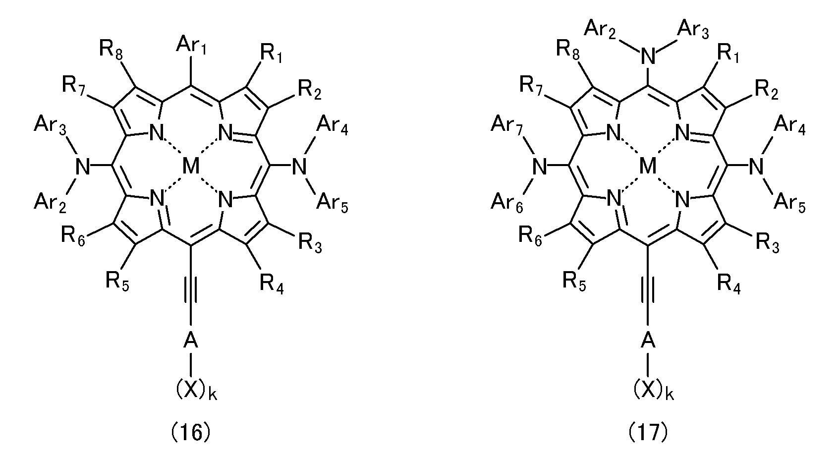
式(16),(17)において、A,X,k,Ar1~Ar5,R1~R8,Mは、それぞれ式(2)における定義と同義である。Ar6,Ar7は、同一又は相異なり、置換基を有していても良いアリール基を表す。
In the formulas (16) and (17), A, X, k, Ar1 to Ar5, R1 to R8, and M have the same definitions as in the formula (2). Ar6 and Ar7 are the same or different and each represents an aryl group which may have a substituent.
本ポルフィリン錯体は、以下の手順に従って合成することができる。すなわち、本ポルフィリン錯体の製造方法は、以下の各段階を含む。なお、本製造方法の説明において、"ポルフィリン誘導体"は、各段階の状況に応じて、当該ポルフィリン誘導体が金属原子と錯体を形成している状態と、錯体を形成していないフリーの状態との両方を含む概念とする。
This porphyrin complex can be synthesized according to the following procedure. That is, the method for producing the porphyrin complex includes the following steps. In the description of this production method, “porphyrin derivative” means a state in which the porphyrin derivative forms a complex with a metal atom and a free state in which no complex is formed, depending on the situation at each stage. The concept includes both.
第1の段階;4箇所のメソ位のうちの1つが、置換基を有していても良いアリール基で置換されたポルフィリン誘導体を準備する。
第2の段階;第1の段階で得られたポルフィリン誘導体の他のメソ位の1つをハロゲン化し、置換基を有していても良いアリール基とハロゲン原子とで置換されたポルフィリン誘導体のシス体とトランス体との混合物を得る。
第3の段階;第2の段階で得られたシス体とトランス体との混合物から、シス体を分離する。
第4の段階;第3の段階で得られたシス体におけるハロゲン原子を、末端側が保護基で保護されたエチニル基で置換する。
第5の段階;第4の段階で得られたポルフィリン誘導体の残りの2箇所のメソ位をハロゲン化する。
第6の段階;第5の段階で得られたポルフィリン誘導体における2つのハロゲン原子を、それぞれ、ポルフィリン環と共にπ共役系を形成可能な電子供与性基で置換する。
第7の段階;第6の段階で得られたポルフィリン誘導体におけるエチニル基を脱保護した後、エチニル基の末端側に、吸着性かつ電子吸引性の官能基で置換されたアリール基(アリール環はさらに置換基を有していても良い)を結合させる。 First stage: A porphyrin derivative in which one of four meso positions is substituted with an aryl group which may have a substituent is prepared.
Second stage; cis of a porphyrin derivative substituted with an aryl group which may have a substituent and a halogen atom by halogenating one of the other meso positions of the porphyrin derivative obtained in the first stage. A mixture of body and trans form is obtained.
Third stage: The cis isomer is separated from the mixture of the cis isomer and the trans isomer obtained in the second stage.
Fourth stage: The halogen atom in the cis isomer obtained in the third stage is substituted with an ethynyl group whose terminal side is protected with a protecting group.
Fifth stage: The remaining two meso positions of the porphyrin derivative obtained in the fourth stage are halogenated.
Sixth stage: Two halogen atoms in the porphyrin derivative obtained in the fifth stage are each substituted with an electron donating group capable of forming a π-conjugated system together with the porphyrin ring.
Seventh step: After deprotecting the ethynyl group in the porphyrin derivative obtained in the sixth step, an aryl group substituted with an adsorptive and electron-withdrawing functional group on the terminal side of the ethynyl group (the aryl ring is Furthermore, an optionally substituted group is bonded.
以下、実施例及び比較例を示して、本ポルフィリン錯体及びそれを用いた色素増感太陽電池について、より詳細に説明する。但し、本発明はこれらの実施例に限定されるわけではない。また、以下の説明における考察は一部推定を含んでおり、その正否によって本発明の範囲が限定されることはないものとする。
Hereinafter, the present porphyrin complex and the dye-sensitized solar cell using the same will be described in more detail with reference to Examples and Comparative Examples. However, the present invention is not limited to these examples. The discussion in the following description includes a part of estimation, and the scope of the present invention is not limited by the correctness.
[実施例1]
5-(4-カルボキシフェニルエチニル)-10,15-ビス(4-メチルフェニル)アミノ-20-(2,4,6-トリメチルフェニル)ポルフィリナト亜鉛(II)(ZnPBAT)を、図2に示す手順に従って合成した。 [Example 1]
The procedure for 5- (4-carboxyphenylethynyl) -10,15-bis (4-methylphenyl) amino-20- (2,4,6-trimethylphenyl) porphyrinatozinc (II) (ZnPBAT) is shown in FIG. Was synthesized according to
5-(4-カルボキシフェニルエチニル)-10,15-ビス(4-メチルフェニル)アミノ-20-(2,4,6-トリメチルフェニル)ポルフィリナト亜鉛(II)(ZnPBAT)を、図2に示す手順に従って合成した。 [Example 1]
The procedure for 5- (4-carboxyphenylethynyl) -10,15-bis (4-methylphenyl) amino-20- (2,4,6-trimethylphenyl) porphyrinatozinc (II) (ZnPBAT) is shown in FIG. Was synthesized according to
5-(2,4,6-トリメチルフェニル)ポルフィリナト亜鉛(II)21(199 mg, 0.405 mmol)をジクロロメタン(100 mL)に溶解させ、この溶液を室温にて撹拌しながら、トリフルオロ酢酸(TFA)(1.0 mL)を添加した。12時間の撹拌後、炭酸水素ナトリウムの飽和水溶液(100 mL)で反応混合物を中和し、その後、ジクロロメタンで抽出した。得られた抽出物を、無水硫酸ナトリウムで乾燥させた。減圧下で溶媒を除去し、赤紫色の固体の5-(2,4,6-トリメチルフェニル)ポルフィリン22を得た。収率は96%であった。なお、ポルフィリン誘導体22の生成は、核磁気共鳴分光法及び高分解能質量分析法により確認した。
5- (2,4,6-trimethylphenyl) porphyrinatozinc (II) 21 (199 mg, 0.405 mmol) was dissolved in dichloromethane (100 mL), and this solution was stirred at room temperature while stirring trifluoroacetic acid (TFA). ) (1.0 mL) was added. After stirring for 12 hours, the reaction mixture was neutralized with a saturated aqueous solution of sodium bicarbonate (100 mL) and then extracted with dichloromethane. The obtained extract was dried over anhydrous sodium sulfate. The solvent was removed under reduced pressure to obtain a reddish purple solid 5- (2,4,6-trimethylphenyl) porphyrin 22. The yield was 96%. The production of porphyrin derivative 22 was confirmed by nuclear magnetic resonance spectroscopy and high resolution mass spectrometry.
5-(2,4,6-トリメチルフェニル)ポルフィリン22(232 mg, 0.541 mmol)及びピリジン(2 mL)をクロロホルム(120 mL)に溶解させ、この溶液を0℃にて撹拌しながら、N-ブロモスクシンイミド(NBS)(91.5 mg, 0.514 mmol)を添加した。30分間の撹拌後、アセトン(5 mL)を添加して反応を終了させ、減圧下で溶媒を除去した。シリカゲルカラム(溶離液;ジクロロメタン/ヘキサン=1/2)で残渣を精製し、粗製の中間体(シス型中間体とトランス型中間体との混合物)を得た。得られた混合物を、シリカゲルを用いたカラムクロマトグラフィー(溶離液;ジクロロメタン/ヘキサン=1/2)に供して、混合物からシス型中間体を分離した。このシス型中間体をジクロロメタン(50 mL)に溶解させ、この溶液に酢酸亜鉛の飽和メタノール溶液(5 mL)を添加して、3時間撹拌した。炭酸水素ナトリウムの飽和水溶液(30 mL)を添加して反応を終了させ、その後、混合物をジクロロメタンで抽出した。得られた抽出物を、無水硫酸ナトリウムで乾燥させた。減圧下で溶媒を除去し、赤紫色の固体の5-ブロモ-10-(2,4,6-トリメチルフェニル)ポルフィリナト亜鉛(II)23を得た。収率は27%であった。なお、ポルフィリン錯体23の生成は、核磁気共鳴分光法、高分解能質量分析法、及びフーリエ変換赤外分光法により確認した。
5- (2,4,6-trimethylphenyl) porphyrin 22 (232 mg, 0.541 mmol) and pyridine (2 mL) were dissolved in chloroform (120 mL), and this solution was stirred at 0 ° C. with N— Bromosuccinimide (NBS) (91.5 mg, 0.514 mmol) was added. After stirring for 30 minutes, acetone (5 mL) was added to terminate the reaction, and the solvent was removed under reduced pressure. The residue was purified with a silica gel column (eluent: dichloromethane / hexane = 1/2) to obtain a crude intermediate (mixture of cis-type intermediate and trans-type intermediate). The obtained mixture was subjected to column chromatography using silica gel (eluent: dichloromethane / hexane = 1/2) to separate a cis-type intermediate from the mixture. This cis-type intermediate was dissolved in dichloromethane (50 mL), a saturated methanol solution of zinc acetate (5 mL) was added to the solution, and the mixture was stirred for 3 hours. The reaction was terminated by the addition of a saturated aqueous solution of sodium bicarbonate (30 mL), and then the mixture was extracted with dichloromethane. The obtained extract was dried over anhydrous sodium sulfate. The solvent was removed under reduced pressure to obtain 5-bromo-10- (2,4,6-trimethylphenyl) porphyrinatozinc (II) 23 as a reddish purple solid. The yield was 27%. The production of porphyrin complex 23 was confirmed by nuclear magnetic resonance spectroscopy, high resolution mass spectrometry, and Fourier transform infrared spectroscopy.
5-ブロモ-10-(2,4,6-トリメチルフェニル)ポルフィリナト亜鉛(II)23(78.5 mg, 0.138 mmol)、トリイソプロピルシリルアセチレン(0.070 mL, 0.30 mmol)、ジクロロビス(トリフェニルホスフィン)パラジウム(20.1 mg, 0.0286 mmol)、ヨウ化銅(8.5 mg, 0.045 mmol)、テトラヒドロフラン(THF)(6 mL)、及びトリエチルアミン(1 mL)を、アルゴン下で4時間かけて穏やかに還流した。減圧下で溶媒を除去した後、シリカゲルカラム(溶離液;ジクロロメタン/ヘキサン=1/4)で残渣を精製した。これにより、赤紫色の固体の5-トリイソプロピルシリルエチニル-10-(2,4,6-トリメチルフェニル)ポルフィリナト亜鉛(II)24を得た。収率は87%であった。なお、ポルフィリン錯体24の生成は、核磁気共鳴分光法、飛行時間型質量分析法、及びフーリエ変換赤外分光法により確認した。
5-bromo-10- (2,4,6-trimethylphenyl) porphyrinatozinc (II) 23 (78.5 mg, 0.138 mmol), triisopropylsilylacetylene (0.070 mL, 0.30 mmol), dichlorobis (triphenylphosphine) palladium ( 20.1 mg, 0.0286 mmol, copper iodide (8.5 mg, 0.045 mmol), tetrahydrofuran (THF) (6 mL), and triethylamine (1 mL) were gently refluxed under argon for 4 hours. After removing the solvent under reduced pressure, the residue was purified with a silica gel column (eluent: dichloromethane / hexane = 1/4). As a result, a red-purple solid 5-triisopropylsilylethynyl-10- (2,4,6-trimethylphenyl) porphyrinatozinc (II) 24 was obtained. The yield was 87%. The production of porphyrin complex 24 was confirmed by nuclear magnetic resonance spectroscopy, time-of-flight mass spectrometry, and Fourier transform infrared spectroscopy.
5-トリイソプロピルシリルエチニル-10-(2,4,6-トリメチルフェニル)ポルフィリナト亜鉛(II)24(80.9 mg, 0.120 mmol)をジクロロメタン(45 mL)とピリジン(1.8 mL)との混合溶媒に溶解させ、この溶液にN-ブロモスクシンイミド(47.1 mg, 0.265 mmol)を添加した。30分間の撹拌後、アセトン(4.5 mL)を添加して反応を終了させ、減圧下で溶媒を除去した。シリカゲルカラム(溶離液;ジクロロメタン/ヘキサン=1/4)で残渣を精製し、赤紫色の固体の5,10-ジブロモ-15-トリイソプロピルシリルエチニル-20-(2,4,6-トリメチルフェニル)ポルフィリナト亜鉛(II)25を得た。収率は50%であった。なお、ポルフィリン錯体25の生成は、飛行時間型質量分析法により確認した。
Dissolve 5-triisopropylsilylethynyl-10- (2,4,6-trimethylphenyl) porphyrinatozinc (II) 24 (80.9 mg, 0.120 mmol) in a mixed solvent of dichloromethane (45 ジ ク ロ ロ メ タ ン mL) and pyridine (1.8 mL) N-bromosuccinimide (47.1 mg, 0.265 mmol) was added to the solution. After stirring for 30 minutes, acetone (4.5 mL) was added to terminate the reaction, and the solvent was removed under reduced pressure. The residue was purified with a silica gel column (eluent: dichloromethane / hexane = 1/4) and reddish purple solid 5,10-dibromo-15-triisopropylsilylethynyl-20- (2,4,6-trimethylphenyl) Porphyrinato zinc (II) 25 was obtained. The yield was 50%. The production of porphyrin complex 25 was confirmed by time-of-flight mass spectrometry.
ビス(4-メチルフェニル)アミン(95.2 mg, 0.483 mmol)をトルエン(5 mL)に溶解させ、-78℃のアルゴン下で、この溶液に1.6Mのn-ブチルリチウムのヘキサン溶液(0.29 mL, 0.47 mmol)を添加した。1時間の撹拌後、反応温度を室温まで上昇させた。この反応溶液に、5,10-ジブロモ-15-トリイソプロピルシリルエチニル-20-(2,4,6-トリメチルフェニル)ポルフィリナト亜鉛(II)25(49.6 mg, 0.0598 mmol)、トルエン(10 mL)、ビス(ジフェニルホスフィノ)ジフェニルエーテル(DPEphos)(24.1 mg, 0.0447 mmol)、及び酢酸パラジウム(6.7 mg, 0.030 mmol)の混合溶液を添加した。得られた混合溶液を、アルゴン下で4時間かけて穏やかに還流した。減圧下で溶媒を除去した後、シリカゲルカラム(溶離液;ジクロロメタン/ヘキサン=1/4)で残渣を精製した。これにより、緑色の固体の5,10-ビス(ビス(4-メチルフェニル)アミノ)-15-トリイソプロピルシリルエチニル-20-(2,4,6-トリメチルフェニル)ポルフィリナト亜鉛(II)26を得た。収率は61%であった。なお、ポルフィリン錯体26の生成は、飛行時間型質量分析法により確認した。
Bis (4-methylphenyl) amine (95.2 mg, 0.483 mmol) was dissolved in toluene (5 mL), and 1.6M n-butyllithium in hexane (0.29 mL) was added to this solution under argon at -78 ° C. , 0.47 mmol). After stirring for 1 hour, the reaction temperature was raised to room temperature. To this reaction solution, 5,10-dibromo-15-triisopropylsilylethynyl-20- (2,4,6-trimethylphenyl) porphyrinatozinc (II) 25 (49.6 mg, 0.0598 mmol), toluene (10 mL), A mixed solution of bis (diphenylphosphino) diphenyl ether (DPEphos) (24.1 mg, 0.0447 mmol) and palladium acetate (6.7 mg, 0.030 mmol) was added. The resulting mixed solution was gently refluxed under argon for 4 hours. After removing the solvent under reduced pressure, the residue was purified with a silica gel column (eluent: dichloromethane / hexane = 1/4). As a result, green solid 5,10-bis (bis (4-methylphenyl) amino) -15-triisopropylsilylethynyl-20- (2,4,6-trimethylphenyl) porphyrinatozinc (II) 26 was obtained. It was. The yield was 61%. In addition, the production | generation of the porphyrin complex 26 was confirmed by the time-of-flight mass spectrometry.
5,10-ビス(ビス(4-メチルフェニル)アミノ)-15-トリイソプロピルシリルエチニル-20-(2,4,6-トリメチルフェニル)ポルフィリナト亜鉛(II)26をテトラヒドロフラン(5 mL)に溶解させ、この溶液に1.0Mのフッ化テトラ-n-ブチルアンモニウム(TBAF)のテトラヒドロフラン溶液(0.19 mL)を添加した。得られた混合溶液を、アルゴン下室温にて30分間撹拌した。その後、水を添加して反応を終了させ、得られた混合溶液をジクロロメタンで抽出した。得られた抽出物(有機相)を無水硫酸ナトリウムで乾燥させ、減圧下で溶媒を除去した。残渣を4-ヨード安息香酸(44.0 mg, 0.177 mmol)と共にテトラヒドロフラン(10 mL)とトリエチルアミン(1.7 mL)との混合溶媒に溶解させた。10分間の脱気後、トリス(ジベンジリデンアセトン)ジパラジウム(Pd2(dba)3)(10.0 mg, 0.0109 mmol)とトリフェニルアルシン(22.0 mg, 0.0718 mmol)とをさらに添加した。得られた混合溶液を、アルゴン下で4時間還流した。減圧下で溶媒を除去した後、シリカゲルカラム(溶離液;ジクロロメタン/メタノール=20/1)で残渣を精製した。再結晶法による精製をさらに経て、緑色の固体の5-(カルボキシフェニルエチニル)-10,15-ビス(ビス(4-メチルフェニル)アミノ)-20-(2,4,6-トリメチルフェニル)ポルフィリナト亜鉛(II)(ZnPBAT)を得た。収率は79%であった。なお、ZnPBATの生成は、核磁気共鳴分光法、高分解能質量分析法、及びフーリエ変換赤外分光法により確認した。
5,10-bis (bis (4-methylphenyl) amino) -15-triisopropylsilylethynyl-20- (2,4,6-trimethylphenyl) porphyrinatozinc (II) 26 was dissolved in tetrahydrofuran (5 mL). To this solution was added 1.0 M tetra-n-butylammonium fluoride (TBAF) in tetrahydrofuran (0.19 mL). The resulting mixed solution was stirred at room temperature for 30 minutes under argon. Thereafter, water was added to terminate the reaction, and the resulting mixed solution was extracted with dichloromethane. The obtained extract (organic phase) was dried over anhydrous sodium sulfate, and the solvent was removed under reduced pressure. The residue was dissolved in 4-iodobenzoic acid (44.0 mg, 0.177 mmol) in a mixed solvent of tetrahydrofuran (10 mL) and triethylamine (1.7 mL). After degassing for 10 minutes, tris (dibenzylideneacetone) dipalladium (Pd2 (dba) 3) (10.0 mg, 0.0109 mmol) and triphenylarsine (22.0 mg, 0.0718 mmol) were further added. The resulting mixed solution was refluxed for 4 hours under argon. After removing the solvent under reduced pressure, the residue was purified with a silica gel column (eluent: dichloromethane / methanol = 20/1). After further purification by recrystallization, green solid 5- (carboxyphenylethynyl) -10,15-bis (bis (4-methylphenyl) amino) -20- (2,4,6-trimethylphenyl) porphyrinato Zinc (II) (ZnPBAT) was obtained. The yield was 79%. The formation of ZnPBAT was confirmed by nuclear magnetic resonance spectroscopy, high resolution mass spectrometry, and Fourier transform infrared spectroscopy.
[比較例]
Hsieh, C.-P. et al. J. Mater. Chem. 20, 1127-1134 (2010) に記載された方法に従い、5-(カルボキシフェニルエチニル)-10,20-ビス(3,5-ジ(t-ブチル)フェニル)-15-ビス(4-ヘキシルフェニル)アミノポルフィリナト亜鉛(II)(YD2;図4を参照)を得た。また、米国特許出願公開第2013/0042916号明細書に記載された方法に従い、5-(カルボキシフェニル)-10,15-ビス(ビス(4-メチルフェニル)アミノ)-20-(2,4,6-トリメチルフェニル)ポルフィリナト亜鉛(II)(ZnPBA;図4を参照)を得た。 [Comparative example]
According to the method described in Hsieh, C.-P. et al. J. Mater. Chem. 20, 1127-1134 (2010), 5- (carboxyphenylethynyl) -10,20-bis (3,5-di- (T-Butyl) phenyl) -15-bis (4-hexylphenyl) aminoporphyrinato zinc (II) (YD2; see FIG. 4) was obtained. In addition, according to the method described in US Patent Application Publication No. 2013/0042916, 5- (carboxyphenyl) -10,15-bis (bis (4-methylphenyl) amino) -20- (2,4,4) 6-Trimethylphenyl) porphyrinato zinc (II) (ZnPBA; see FIG. 4) was obtained.
[評価試験]
本ポルフィリン錯体(ZnPBAT)及び比較例のポルフィリン錯体(YD2,ZnPBA)について、増感色素としての特能の評価を行った。また、これらを増感色素として用いた色素増感太陽電池を作製し、電池特性の評価を行った。 [Evaluation test]
The present porphyrin complex (ZnPBAT) and the porphyrin complex of the comparative example (YD2, ZnPBA) were evaluated for their abilities as sensitizing dyes. Moreover, the dye-sensitized solar cell which used these as a sensitizing dye was produced, and the battery characteristic was evaluated.
<光吸収特性>
ZnPBAT,YD2,ZnPBAのそれぞれについて、エタノール溶液における光吸収特性の評価を行った。図3は、各ポルフィリン錯体の紫外可視近赤外領域における光吸収スペクトルを示している。図3において、縦軸はモル吸光係数であり、横軸は波長である。この図から、2つのジアリールアミノ基を有するZnPBATの光吸収スペクトルは、1つのジアリールアミノ基だけを有するYD2の光吸収スペクトルに比べてブロード化していることが理解できる。また、ZnPBATの光吸収スペクトルは、YD2及びZnPBAの光吸収スペクトルに比べて長波長化していることが理解できる。特に、ポルフィリンのQ帯に対応する長波長側の吸収帯におけるピーク波長どうしを比較すると、ZnPBATのピーク波長は、YD2のピーク波長に比べて15nm以上長く、ZnPBAのピーク波長に比べると30nm以上も長くなっていた。さらに、長波長側の吸収帯における積分値どうしを比較すると、ポルフィリン環に結合したエチニル基(三重結合)を有するZnPBATは、そのような官能基を有していないZnPBAに比べて当該吸収帯が大きく増強されていることが理解できる。これらの結果は、ZnPBATが、YD2及びZnPBAに比べて、可視領域及び近赤外領域における集光特性をさらに向上させたことを示している。 <Light absorption characteristics>
Each of ZnPBAT, YD2, and ZnPBA was evaluated for light absorption characteristics in an ethanol solution. FIG. 3 shows the light absorption spectrum of each porphyrin complex in the ultraviolet-visible near-infrared region. In FIG. 3, the vertical axis represents the molar extinction coefficient, and the horizontal axis represents the wavelength. From this figure, it can be understood that the light absorption spectrum of ZnPBAT having two diarylamino groups is broader than the light absorption spectrum of YD2 having only one diarylamino group. Moreover, it can be understood that the light absorption spectrum of ZnPBAT has a longer wavelength than the light absorption spectra of YD2 and ZnPBA. In particular, when comparing the peak wavelengths in the absorption band on the long wavelength side corresponding to the Q band of porphyrin, the peak wavelength of ZnPBAT is 15 nm or more longer than the peak wavelength of YD2, and 30 nm or more compared to the peak wavelength of ZnPBA. It was long. Further, when comparing the integrated values in the absorption band on the long wavelength side, ZnPBAT having an ethynyl group (triple bond) bonded to a porphyrin ring has a higher absorption band than ZnPBA having no such functional group. It can be understood that it is greatly enhanced. These results indicate that ZnPBAT further improved the light collection characteristics in the visible region and the near-infrared region as compared with YD2 and ZnPBA.
<エネルギーダイアグラム>
ZnPBAT,YD2,ZnPBAのそれぞれの分子軌道のエネルギー準位を算出した。図4は、各ポルフィリン錯体のエネルギーダイアグラムを示している。図4において、縦軸は標準水素電極を比較電極とした酸化還元電位であり、各ポルフィリン錯体における上側の直線がLUMOを表し、下側の直線がHOMOを表す。この図から、ZnPBATは、同程度のLUMOレベルを有するYD2に比べてHOMOレベルが上昇していることが理解できる。また、ZnPBATは、同程度のHOMOレベルを有するZnPBAに比べてLUMOレベルが低下していることが理解できる。これにより、ZnPBATは、YD2及びZnPBAに比べてHOMO-LUMOギャップが減少していることが理解できる。これらの結果は、ZnPBATが、YD2及びZnPBAに比べて、金属酸化物粒子や電解質中のイオンとの間での効率的な電荷移動を可能とすることを示唆している。 <Energy diagram>
The energy level of each molecular orbital of ZnPBAT, YD2, ZnPBA was calculated. FIG. 4 shows an energy diagram of each porphyrin complex. In FIG. 4, the vertical axis represents the oxidation-reduction potential using a standard hydrogen electrode as a reference electrode, the upper straight line in each porphyrin complex represents LUMO, and the lower straight line represents HOMO. From this figure, it can be understood that ZnPBAT has an increased HOMO level compared to YD2 having a comparable LUMO level. It can also be seen that ZnPBAT has a lower LUMO level than ZnPBA having a comparable HOMO level. Accordingly, it can be understood that ZnPBAT has a reduced HOMO-LUMO gap compared to YD2 and ZnPBA. These results suggest that ZnPBAT enables efficient charge transfer between metal oxide particles and ions in the electrolyte as compared with YD2 and ZnPBA.
<色素増感太陽電池の作製>
FTOガラスの表面にTiO2粒子からなる多孔質層を積層し、酸化チタン電極を作製した。多孔質層は、平均粒径20nmのTiO2粒子から構成される約8μmの層、平均粒径30nmのTiO2粒子から構成される約4μmの層、及び平均粒径400nmのTiO2粒子から構成される約4μmの層からなる3層構造とした。作製した酸化チタン電極を、各ポルフィリン錯体(ZnPBAT,YD2,ZnPBA)の0.2mMエタノール溶液に浸漬し、TiO2粒子の表面に各ポルフィリン錯体が吸着した色素修飾酸化チタン電極(光電極)を得た。また、FTOガラスの表面に白金の薄膜を形成して、対極を作製した。これらの色素修飾酸化チタン電極と対極とをスペーサを介して対向させ、電解液を封入して色素増感太陽電池を作製した。電解液としては、1.0Mの1,3-ジメチルイミダゾリウムイオダイド、0.03Mのヨウ素、0.05Mのヨウ化リチウム、0.1Mのグアニジンチオシアナート、及び0.5Mの4-t-ブチルピリジンからなる電解質を、アセトニトリルとバレロニトリルとの混合溶媒(体積比で85:15)に溶解させたものを用いた。 <Preparation of dye-sensitized solar cell>
A porous layer made of TiO2 particles was laminated on the surface of FTO glass to prepare a titanium oxide electrode. The porous layer is about 8 μm layer composed ofTiO 2 particles having an average particle diameter of 20 nm, about 4 μm layer composed of TiO 2 particles having an average particle diameter of 30 nm, and about TiO 2 particles having an average particle diameter of 400 nm. A three-layer structure consisting of 4 μm layers was formed. The prepared titanium oxide electrode was immersed in a 0.2 mM ethanol solution of each porphyrin complex (ZnPBAT, YD2, ZnPBA) to obtain a dye-modified titanium oxide electrode (photoelectrode) in which each porphyrin complex was adsorbed on the surface of TiO2 particles. . A counter electrode was prepared by forming a platinum thin film on the surface of the FTO glass. The dye-modified titanium oxide electrode and the counter electrode were opposed to each other through a spacer, and an electrolyte solution was sealed to prepare a dye-sensitized solar cell. The electrolyte included 1.0M 1,3-dimethylimidazolium iodide, 0.03M iodine, 0.05M lithium iodide, 0.1M guanidine thiocyanate, and 0.5M 4-t. A solution obtained by dissolving an electrolyte composed of butylpyridine in a mixed solvent of acetonitrile and valeronitrile (85:15 by volume) was used.
FTOガラスの表面にTiO2粒子からなる多孔質層を積層し、酸化チタン電極を作製した。多孔質層は、平均粒径20nmのTiO2粒子から構成される約8μmの層、平均粒径30nmのTiO2粒子から構成される約4μmの層、及び平均粒径400nmのTiO2粒子から構成される約4μmの層からなる3層構造とした。作製した酸化チタン電極を、各ポルフィリン錯体(ZnPBAT,YD2,ZnPBA)の0.2mMエタノール溶液に浸漬し、TiO2粒子の表面に各ポルフィリン錯体が吸着した色素修飾酸化チタン電極(光電極)を得た。また、FTOガラスの表面に白金の薄膜を形成して、対極を作製した。これらの色素修飾酸化チタン電極と対極とをスペーサを介して対向させ、電解液を封入して色素増感太陽電池を作製した。電解液としては、1.0Mの1,3-ジメチルイミダゾリウムイオダイド、0.03Mのヨウ素、0.05Mのヨウ化リチウム、0.1Mのグアニジンチオシアナート、及び0.5Mの4-t-ブチルピリジンからなる電解質を、アセトニトリルとバレロニトリルとの混合溶媒(体積比で85:15)に溶解させたものを用いた。 <Preparation of dye-sensitized solar cell>
A porous layer made of TiO2 particles was laminated on the surface of FTO glass to prepare a titanium oxide electrode. The porous layer is about 8 μm layer composed of
<電池特性>
ZnPBAT,YD2,ZnPBAのいずれかを増感色素として含む色素増感太陽電池(以下、それぞれ「ZnPBAT電池」,「YD2電池」,「ZnPBA電池」と称する)のそれぞれについて、電池特性の評価を行った。電池特性は、主にエネルギー変換効率(η)、短絡電流密度、開放電圧、及び曲線因子に基づいて評価した。 <Battery characteristics>
Evaluation of battery characteristics of each of dye-sensitized solar cells containing any of ZnPBAT, YD2, and ZnPBA as sensitizing dyes (hereinafter referred to as “ZnPBAT battery”, “YD2 battery”, and “ZnPBA battery”, respectively) It was. The battery characteristics were evaluated mainly based on energy conversion efficiency (η), short circuit current density, open circuit voltage, and fill factor.
まず、各電池の初期のエネルギー変換効率の変化を検証した。図5は、その結果を示している。図5において、縦軸はエネルギー変換効率であり、横軸は浸漬時間である。この図から、YD2電池やZnPBA電池では、浸漬時間に対するエネルギー変換効率は、TiO2粒子表面への増感色素の吸着挙動に適合するように変化し、約3時間で最大値に達することが理解できる。一方、ZnPBAT電池では、エネルギー変換効率は、約1時間の浸漬時間のうちに急速に上昇して最大値を示し、その後若干低下して所定値に収束することが理解できる。このように、ZnPBAT電池は、YD2電池やZnPBA電池と比べて、初期におけるエネルギー変換効率の変化態様が全く異なることが分かった。これは、詳細は明らかではないが、TiO2粒子上でのポルフィリン錯体の会合状態の差異に基づく現象であると予測される。
First, changes in the initial energy conversion efficiency of each battery were verified. FIG. 5 shows the result. In FIG. 5, the vertical axis represents energy conversion efficiency, and the horizontal axis represents immersion time. From this figure, it can be understood that, in the YD2 battery and the ZnPBA battery, the energy conversion efficiency with respect to the immersion time changes so as to match the adsorption behavior of the sensitizing dye on the TiO2 particle surface and reaches the maximum value in about 3 hours. . On the other hand, in the ZnPBAT battery, it can be understood that the energy conversion efficiency rapidly increases during the immersion time of about 1 hour, shows a maximum value, and then decreases slightly and converges to a predetermined value. Thus, it was found that the ZnPBAT battery has completely different changes in the energy conversion efficiency in the initial stage compared to the YD2 battery and the ZnPBA battery. Although this is not clear in detail, it is expected to be a phenomenon based on the difference in the association state of the porphyrin complex on the TiO2 particles.
TiO2粒子上におけるポルフィリン錯体の凝集を抑制するため、各ポルフィリン錯体のエタノール溶液中に、共吸着剤としてケノデオキシコール酸(CDCA)を添加した。図6は、ケノデオキシコール酸の添加量とエネルギー変換効率との関係を示すグラフである。縦軸はエネルギー変換効率であり、横軸は添加量である。この図から、各ポルフィリン錯体に対するケノデオキシコール酸の添加量を、ZnPBATでは約10等量、YD2では約2等量、ZnPBAでは約5等量とすることが最適であることが分かった。これらの結果は、TiO2粒子上でのポルフィリン錯体の会合状態の差異を反映していると考えられる。
In order to suppress aggregation of the porphyrin complex on the TiO2 particles, chenodeoxycholic acid (CDCA) was added as a co-adsorbent to the ethanol solution of each porphyrin complex. FIG. 6 is a graph showing the relationship between the amount of chenodeoxycholic acid added and the energy conversion efficiency. The vertical axis represents energy conversion efficiency, and the horizontal axis represents the amount added. From this figure, it was found that the amount of chenodeoxycholic acid added to each porphyrin complex was optimally about 10 equivalents for ZnPBAT, about 2 equivalents for YD2, and about 5 equivalents for ZnPBA. These results are considered to reflect the difference in the state of association of the porphyrin complex on the TiO2 particles.
各ポルフィリン錯体に応じた最適量のケノデオキシコール酸をそれぞれ添加した色素増感太陽電池を暗所に放置して、エージングによる効果を検証した。図7は、その結果を示している。図7において、縦軸はエネルギー変換効率であり、横軸はエージング時間である。この図に示されているように、ZnPBAT電池のエネルギー変換効率は、約36時間のエージングにより最高値10.1%に達した。これは、ZnPBA電池における最高値8.3%を大幅に上回る値であり(およそ2割増し)、YD2電池における最高値9.1%をも有意に上回る値である(およそ1割増し)。なお、YD2電池に関しては、Bessho, T. et al. Angew. Chem. Int. Ed. 49, 6646-6649 (2010) において11%のエネルギー変換効率が報告されているが、本発明者らによる追試験ではそれを確認することはできなかった。これは、必ずしも最適化が十分ではなかったためであると考えられる。この点を考慮すると、今後の研究によって色素増感太陽電池の仕様がさらに最適化されれば、ZnPBAT電池で、11%をさらに上回るエネルギー変換効率が達成されると期待される。
The dye-sensitized solar cell added with the optimum amount of chenodeoxycholic acid according to each porphyrin complex was left in the dark to verify the effect of aging. FIG. 7 shows the result. In FIG. 7, the vertical axis represents energy conversion efficiency, and the horizontal axis represents aging time. As shown in this figure, the energy conversion efficiency of the ZnPBAT cell reached a maximum value of 10.1% after aging for about 36 hours. This is a value that greatly exceeds the maximum value of 8.3% in the ZnPBA battery (approximately 20% increase), and is also significantly higher than the maximum value of 9.1% in the YD2 battery (approximately 10% increase). Regarding YD2 batteries, 11% energy conversion efficiency was reported in Bessho, T. et al. Angew. Chem. Int. Ed. 49, 6646-6649 (2010). The test failed to confirm it. This is probably because the optimization was not always sufficient. Considering this point, if the specifications of the dye-sensitized solar cell are further optimized by future research, it is expected that an energy conversion efficiency exceeding 11% will be achieved in the ZnPBAT cell.
本評価試験における最適化条件の下、各電池の電流-電圧特性を検証した。図8は、その結果を示している。図8において、縦軸は電流であり、横軸は電圧である。この図から、各電池の短絡電流密度(JSC)、開放電圧(VOC)、及び曲線因子(FF)をそれぞれ算出した。その結果を、エネルギー変換効率の最高値と合わせて図9にまとめた。曲線因子は、各電池においてほぼ同一であった。開放電圧は、YD2電池で若干大きかったが、有意と言えるほどではなかった。短絡電流密度は、YD2電池やZnPBA電池に比べて、ZnPBAT電池が優れていた。ZnPBAT電池の短絡電流密度は、ZnPBA電池における値を大幅に上回っており(およそ2割増し)、YD2電池における値を有意に上回っていた(およそ1割増し)。これらの結果から、総合的な電池特性に注目した場合に、ZnPBAT電池が非常に優れていることが確認された。
The current-voltage characteristics of each battery were verified under the optimization conditions in this evaluation test. FIG. 8 shows the result. In FIG. 8, the vertical axis represents current, and the horizontal axis represents voltage. From this figure, the short circuit current density (JSC), open circuit voltage (VOC), and fill factor (FF) of each battery were calculated. The results are summarized in FIG. 9 together with the maximum energy conversion efficiency. The fill factor was almost the same in each battery. The open circuit voltage was slightly higher for the YD2 battery, but not so significant. The short-circuit current density of the ZnPBAT battery was superior to that of the YD2 battery or ZnPBA battery. The short-circuit current density of the ZnPBAT battery was significantly higher than that of the ZnPBA battery (approximately 20% increase), and significantly higher than that of the YD2 battery (approximately 10% increase). From these results, it was confirmed that the ZnPBAT battery was very excellent when focusing on the overall battery characteristics.
各電池について、分光感度特性の評価を行った。図10は、各電池の作用スペクトルを示している。図10において、縦軸は外部量子効率(IPCE)であり、横軸は波長である。この図から、650~800nmの波長領域において、ZnPBAT電池の外部量子効率が、YD2電池やZnPBA電池に比べて向上していることが理解できる。また、図10と図3とを合わせて考慮すると、650~800nmの波長領域における外部量子効率の向上は、増感色素であるZnPBAT自体の集光特性の向上と正の相関を有していることが理解できる。すなわち、ZnPBAT電池においては、集光特性の向上が電池特性の向上のために有効に働いていることが理解できる。
The spectral sensitivity characteristics of each battery were evaluated. FIG. 10 shows the action spectrum of each battery. In FIG. 10, the vertical axis represents external quantum efficiency (IPCE), and the horizontal axis represents wavelength. From this figure, it can be understood that the external quantum efficiency of the ZnPBAT battery is improved in comparison with the YD2 battery and the ZnPBA battery in the wavelength region of 650 to 800 nm. Further, considering FIG. 10 and FIG. 3 together, the improvement of the external quantum efficiency in the wavelength region of 650 to 800 nm has a positive correlation with the improvement of the light condensing characteristic of the sensitizing dye ZnPBAT itself. I understand that. That is, in the ZnPBAT battery, it can be understood that the improvement of the light collection characteristic works effectively for the improvement of the battery characteristic.
このように、本ポルフィリン錯体は、増強されたプッシュ・プル型の分子構造を有すること、三重結合を有するアリールエチニル基を含む吸着基を用いること、複数の電子供与性基を吸着基に対してより対称性が低くなるように導入していること、を組み合わせた点に特徴を有する。これにより、可視領域及び近赤外領域における集光特性を向上させることができるとともに、それを色素増感太陽電池における増感色素として用いた場合に、電池特性をも有効に向上させることができる。
Thus, the porphyrin complex has an enhanced push-pull type molecular structure, uses an adsorbing group including an arylethynyl group having a triple bond, and a plurality of electron donating groups with respect to the adsorbing group. It is characterized in that it is introduced so as to have lower symmetry. Thereby, the condensing characteristic in the visible region and the near-infrared region can be improved, and when it is used as a sensitizing dye in a dye-sensitized solar cell, the battery characteristic can also be improved effectively. .
[実施例2]
5-(4-カルボキシフェニルエチニル)-10,15-ビス(ビス(4-メチルフェニル)アミノ)-20-(2,6-ビス(オクチルオキシ)フェニル)ポルフィリナト亜鉛(II)(ZnPBAT-o-C8)を合成した。ZnPBAT-o-C8の合成に際しては、図11に示す手順に従って、4箇所のメソ位のうちの1つが2,6-ジオクチルオキシフェニル基で置換されたポルフィリン誘導体を準備した。このポルフィリン誘導体を用いて、それ以降は実施例1に類似する手順に従って、ZnPBAT-o-C8を合成した。ZnPBAT-o-C8も、ZnPBATと同様の集電特性を有するとともに、ZnPBATと同様に電池特性を向上させ得ることが確認された。また、ZnPBAT-o-C8は、ZnPBATと比較して、電解液との界面におけるイオンへの電子の逆移動や、ポルフィリン錯体どうしの会合を抑制し得ることを示唆する結果が得られた。 [Example 2]
5- (4-Carboxyphenylethynyl) -10,15-bis (bis (4-methylphenyl) amino) -20- (2,6-bis (octyloxy) phenyl) porphyrinato zinc (II) (ZnPBAT-o- C8) was synthesized. In synthesizing ZnPBAT-o-C8, a porphyrin derivative in which one of four meso positions was substituted with a 2,6-dioctyloxyphenyl group was prepared according to the procedure shown in FIG. From this porphyrin derivative, ZnPBAT-o-C8 was synthesized according to a procedure similar to that in Example 1 thereafter. It was confirmed that ZnPBAT-o-C8 also has the same current collecting characteristics as ZnPBAT and can improve the battery characteristics like ZnPBAT. In addition, a result suggesting that ZnPBAT-o-C8 can suppress the reverse transfer of electrons to ions and the association between porphyrin complexes at the interface with the electrolytic solution as compared with ZnPBAT.
[実施例3]
5-(4-カルボキシフェニルエチニル)-10,15-ビス(ビス(4-メチルフェニル)アミノ)-2,20-(4,5-(1-オクチルオキシナフタレン))ポルフィリナト亜鉛(II)(ZnPBAT-fused)を合成した。ZnPBAT-fusedの合成に際しては、図12に示す手順に従って、4箇所のメソ位のうちの1つが4-オクチルオキシナフチル基で置換されたポルフィリン誘導体を準備した。このポルフィリン誘導体を用いて、それ以降は実施例1に類似する手順に従って、ZnPBAT-fusedを合成した。なお、ポルフィリン環に2つの電子供与性基を導入した後のポルフィリン誘導体のジクロロエタン溶液に塩化鉄及びニトロメタンを添加して、4-オクチルオキシナフチル基とポルフィリン環とを縮環させた。その後、エチニル基の末端にカルボキシフェニル基を導入してZnPBAT-fusedを得た。ZnPBAT-fusedも、ZnPBATと同様の集電特性を有するとともに、ZnPBATと同様に電池特性を向上させ得ることが確認された。 [Example 3]
5- (4-Carboxyphenylethynyl) -10,15-bis (bis (4-methylphenyl) amino) -2,20- (4,5- (1-octyloxynaphthalene)) porphyrinatozinc (II) (ZnPBAT -Fused) was synthesized. In synthesizing ZnPBAT-fused, a porphyrin derivative in which one of four meso positions was substituted with a 4-octyloxynaphthyl group was prepared according to the procedure shown in FIG. Using this porphyrin derivative, ZnPBAT-fused was synthesized according to a procedure similar to that in Example 1 thereafter. In addition, iron chloride and nitromethane were added to the dichloroethane solution of the porphyrin derivative after introducing two electron donating groups into the porphyrin ring, thereby condensing the 4-octyloxynaphthyl group and the porphyrin ring. Thereafter, a carboxyphenyl group was introduced at the end of the ethynyl group to obtain ZnPBAT-fused. It has been confirmed that ZnPBAT-fused has the same current collecting characteristics as ZnPBAT and can improve the battery characteristics in the same manner as ZnPBAT.
本明細書において開示された実施形態及びそれを具体化した実施例は全ての点で例示であって、本発明の範囲はそれらによって限定されることはないと理解されるべきである。当業者であれば、上述した実施形態及び実施例に基づき、本発明の趣旨を逸脱しない範囲で、適宜改変が可能であることを容易に理解できるであろう。従って、本発明の趣旨を逸脱しない範囲で改変された別の実施形態も、当然、本発明の範囲に含まれる。
It should be understood that the embodiments disclosed herein and examples embodying the embodiments are illustrative in all respects, and the scope of the present invention is not limited thereby. Those skilled in the art will readily understand that appropriate modifications can be made without departing from the spirit of the present invention based on the above-described embodiments and examples. Accordingly, other embodiments modified without departing from the spirit of the present invention are naturally included in the scope of the present invention.
本発明は、色素増感太陽電池用の増感色素として有効に利用することができる。
The present invention can be effectively used as a sensitizing dye for a dye-sensitized solar cell.
1 色素増感太陽電池
10 光電極(第一電極)
14 多孔質層
15 金属酸化物粒子
16 増感色素(ポルフィリン錯体)
20 対極(第二電極)
30 電解液 1 Dye-sensitizedsolar cell 10 Photoelectrode (first electrode)
14Porous layer 15 Metal oxide particle 16 Sensitizing dye (porphyrin complex)
20 Counter electrode (second electrode)
30 electrolyte
10 光電極(第一電極)
14 多孔質層
15 金属酸化物粒子
16 増感色素(ポルフィリン錯体)
20 対極(第二電極)
30 電解液 1 Dye-sensitized
14
20 Counter electrode (second electrode)
30 electrolyte
Claims (5)
- 金属原子と、この金属原子に配位したポルフィリン誘導体と、からなるポルフィリン錯体であって、
前記ポルフィリン誘導体は、ポルフィリン環に結合された1つの吸着基と、前記ポルフィリン環と共にπ共役系を形成する状態で当該ポルフィリン環に結合された少なくとも2つの電子供与性基と、を有し、
前記吸着基は、吸着性かつ電子吸引性の官能基で置換されたアリールエチニル基(アリール環はさらに置換基を有していても良い)であり、
少なくとも2つの前記電子供与性基が、前記アリールエチニル基に対して非対称な位置関係で前記ポルフィリン環に結合しているポルフィリン錯体。 A porphyrin complex comprising a metal atom and a porphyrin derivative coordinated to the metal atom,
The porphyrin derivative has one adsorbing group bonded to the porphyrin ring and at least two electron donating groups bonded to the porphyrin ring in a state of forming a π-conjugated system with the porphyrin ring,
The adsorptive group is an arylethynyl group substituted with an adsorptive and electron-withdrawing functional group (the aryl ring may further have a substituent),
A porphyrin complex in which at least two of the electron donating groups are bonded to the porphyrin ring in an asymmetric positional relationship with respect to the arylethynyl group. - 前記アリールエチニル基が、前記ポルフィリン環の4箇所のメソ位の1つに結合しており、
2つの前記電子供与性基が、前記アリールエチニル基が結合したメソ位に対して、隣接するメソ位及び対向するメソ位にそれぞれ結合している請求項1に記載のポルフィリン錯体。 The arylethynyl group is bonded to one of the four meso positions of the porphyrin ring;
2. The porphyrin complex according to claim 1, wherein the two electron donating groups are respectively bonded to an adjacent meso position and an opposite meso position with respect to the meso position to which the arylethynyl group is bonded. - 前記電子供与性基は、ジアリールアミノ基(アリール環は置換基を有していても良い)である請求項1又は2に記載のポルフィリン錯体。 The porphyrin complex according to claim 1 or 2, wherein the electron donating group is a diarylamino group (the aryl ring may have a substituent).
- 下記の一般式で表される請求項1から3のいずれか一項に記載のポルフィリン錯体。

Aは、置換基を有していても良いアリーレン基を表し、
Xは、カルボキシル基、水酸基、スルホン基、リン酸基、又はホスホン酸基を表し、
kは、5以下の整数を表し、
Er1,Er2は、同一又は相異なり、ポルフィリン環と共にπ共役系を形成可能な電子供与性基を表し、
Ar1は、置換基を有していても良いアリール基を表し、
R1~R8は、同一又は相異なり、水素原子、置換基を有していても良いアルキル基、置換基を有していても良いアリール基、又はハロゲン原子を表し、
Ar1とR6及びR7の少なくとも一方とは、それらの間で縮合環を形成していても良く、
Mは、金属原子を表す。] The porphyrin complex as described in any one of Claim 1 to 3 represented by the following general formula.
A represents an arylene group which may have a substituent,
X represents a carboxyl group, a hydroxyl group, a sulfone group, a phosphoric acid group, or a phosphonic acid group,
k represents an integer of 5 or less,
Er1 and Er2 are the same or different and represent an electron donating group capable of forming a π-conjugated system with a porphyrin ring,
Ar1 represents an aryl group which may have a substituent,
R1 to R8 are the same or different and each represents a hydrogen atom, an alkyl group which may have a substituent, an aryl group which may have a substituent, or a halogen atom;
Ar1 and at least one of R6 and R7 may form a condensed ring between them,
M represents a metal atom. ] - 請求項1から4のいずれか一項に記載のポルフィリン錯体を増感色素として金属酸化物の粒子に吸着させてなる多孔質層を有する第一電極と、
前記多孔質層を挟んで前記第一電極に対向して配置される第二電極と、
前記第一電極と前記第二電極との間に封入される電解液と、
を備える色素増感太陽電池。 A first electrode having a porous layer formed by adsorbing the porphyrin complex according to any one of claims 1 to 4 on a metal oxide particle as a sensitizing dye;
A second electrode disposed opposite to the first electrode across the porous layer;
An electrolyte solution sealed between the first electrode and the second electrode;
A dye-sensitized solar cell comprising:
Applications Claiming Priority (2)
| Application Number | Priority Date | Filing Date | Title |
|---|---|---|---|
| JP2013-120079 | 2013-06-06 | ||
| JP2013120079A JP2014237743A (en) | 2013-06-06 | 2013-06-06 | Porphyrin complex and dye-sensitized solar cell |
Publications (1)
| Publication Number | Publication Date |
|---|---|
| WO2014196325A1 true WO2014196325A1 (en) | 2014-12-11 |
Family
ID=52007978
Family Applications (1)
| Application Number | Title | Priority Date | Filing Date |
|---|---|---|---|
| PCT/JP2014/062804 WO2014196325A1 (en) | 2013-06-06 | 2014-05-14 | Porphyrin complex and dye-sensitized solar cell |
Country Status (3)
| Country | Link |
|---|---|
| JP (1) | JP2014237743A (en) |
| TW (1) | TW201509942A (en) |
| WO (1) | WO2014196325A1 (en) |
Families Citing this family (2)
| Publication number | Priority date | Publication date | Assignee | Title |
|---|---|---|---|---|
| TWI474536B (en) * | 2014-07-01 | 2015-02-21 | Nat Univ Chung Hsing | Photosensitive porphyrin dyes for dye-sensitized solar cells |
| JP6935752B2 (en) * | 2018-01-19 | 2021-09-15 | 株式会社アイシン | A sensitizing dye for a dye-sensitized solar cell and a dye-sensitized solar cell including the sensitizing dye. |
Citations (2)
| Publication number | Priority date | Publication date | Assignee | Title |
|---|---|---|---|---|
| US20100125136A1 (en) * | 2008-11-17 | 2010-05-20 | Dc Solar Corp. A Taiwan Corporation | Porphyrin-based photosensitizer dyes for dye-sensitized solar cells |
| CN103044952A (en) * | 2013-01-04 | 2013-04-17 | 北京科技大学 | Asymmetric porphyrin solar cell dye and preparation method thereof |
-
2013
- 2013-06-06 JP JP2013120079A patent/JP2014237743A/en active Pending
-
2014
- 2014-05-14 WO PCT/JP2014/062804 patent/WO2014196325A1/en active Application Filing
- 2014-06-05 TW TW103119480A patent/TW201509942A/en unknown
Patent Citations (2)
| Publication number | Priority date | Publication date | Assignee | Title |
|---|---|---|---|---|
| US20100125136A1 (en) * | 2008-11-17 | 2010-05-20 | Dc Solar Corp. A Taiwan Corporation | Porphyrin-based photosensitizer dyes for dye-sensitized solar cells |
| CN103044952A (en) * | 2013-01-04 | 2013-04-17 | 北京科技大学 | Asymmetric porphyrin solar cell dye and preparation method thereof |
Non-Patent Citations (7)
| Title |
|---|
| IMAHORI, HIROSHI ET AL.: "Effects of meso- diarylamino group of porphyrins as sensitizers in dye-sensitized solar cells on optical, electrochemical, and photovoltaic properties", JOURNAL OF PHYSICAL CHEMISTRY C, vol. 114, no. 23, 2010, pages 10656 - 10665 * |
| KARTHIKEYAN, S. ET AL.: "Zinc-porphyrin based dyes for dye-sensitized solar cells", JOURNAL OF PHYSICAL CHEMISTRY A, vol. 117, no. 42, 3 October 2013 (2013-10-03), pages 10973 - 10979 * |
| KUROTOBI, KEI ET AL.: "Highly asymmetrical porphyrins with enhanced push-pull character for dye-sensitized solar cells", CHEMISTRY - A EUROPEAN JOURNAL, vol. 19, no. 50, 13 November 2013 (2013-11-13), pages 17075 - 17081 * |
| MASI REDDY ET AL.: "Porphyrin sensitizers with n-extended pull units for dye-sensitized solar cells", PHYSICAL CHEMISTRY CHEMICAL PHYSICS, vol. 15, no. 21, 7 June 2013 (2013-06-07), pages 8409 - 8415, XP055228928, DOI: doi:10.1039/c3cp51327k * |
| ORNSO, KRISTIAN B. ET AL.: "Computational screening of functionalized zinc porphyrins for dye sensitized solar cells", PHYSICAL CHEMISTRY CHEMICAL PHYSICS, vol. 15, no. 44, 28 November 2013 (2013-11-28), pages 19478 - 19486 * |
| RIPOLLES-SANCHIS, TERESA ET AL.: "Design and characterization of alkoxy-wrapped push-pull porphyrins for dye-sensitized solar cells", CHEMICAL COMMUNICATIONS, vol. 48, no. 36, 2012, pages 4368 - 4370, XP055228807, DOI: doi:10.1039/c2cc31111a * |
| WU, SUNG-LIN ET AL.: "Design and characterization of porphyrin sensitizers with a push-pull framework for highly efficient dye-sensitized solar cells", ENERGY & ENVIRONMENTAL SCIENCE, vol. 3, no. 7, 2010, pages 949 - 955 * |
Also Published As
| Publication number | Publication date |
|---|---|
| TW201509942A (en) | 2015-03-16 |
| JP2014237743A (en) | 2014-12-18 |
Similar Documents
| Publication | Publication Date | Title |
|---|---|---|
| Yang et al. | Efficient and stable organic DSSC sensitizers bearing quinacridone and furan moieties as a planar π-spacer | |
| Pandey et al. | Alkyl and fluoro-alkyl substituted squaraine dyes: A prospective approach towards development of novel NIR sensitizers | |
| Hua et al. | Bulky dendritic triarylamine-based organic dyes for efficient co-adsorbent-free dye-sensitized solar cells | |
| Seo et al. | Dual-channel anchorable organic dyes with well-defined structures for highly efficient dye-sensitized solar cells | |
| CN103492402A (en) | Improved redox couple for electrochemical and optoelectronic devices | |
| Tan et al. | Novel zinc porphyrin sensitizers for dye-sensitized solar cells: Synthesis and spectral, electrochemical, and photovoltaic properties | |
| Jia et al. | Synthesis of dendritic triphenylamine derivatives for dye-sensitized solar cells | |
| Song et al. | Branched and linear alkoxy chains-wrapped push-pull porphyrins for developing efficient dye-sensitized solar cells | |
| EP3080206B9 (en) | Porphyrin based sensitizer for dye-sensitized solar cell | |
| Qian et al. | Triazatruxene-based organic dyes containing a rhodanine-3-acetic acid acceptor for dye-sensitized solar cells | |
| Qin et al. | Panchromatic donor–acceptor–acceptor sensitizers based on 4H-cyclopenta [2, 1-b: 3, 4-b′] dithiophen-4-one as a strong acceptor for dye-sensitized solar cells | |
| JP5706846B2 (en) | Dye, photoelectric conversion element and photoelectrochemical cell using the same | |
| Narayanaswamy et al. | Simple metal-free dyes derived from triphenylamine for DSSC: A comparative study of two different anchoring group | |
| Cho et al. | Molecular design of donor–acceptor-type cruciform dyes for efficient dyes-sensitized solar cells | |
| Zhang et al. | Synthesis of novel sensitizers with a linear conjugated di (1-benzothieno)[3, 2-b: 2′, 3′-d] pyrrole unit for dye-sensitized solar cells | |
| Wu et al. | Novel 4, 4′-bis (alkylphenyl/alkyloxyphenyl)-2, 2′-bithiophene bridged cyclic thiourea functionalized triphenylamine sensitizers for efficient dye-sensitized solar cells | |
| Shivashimpi et al. | Effect of nature of anchoring groups on photosensitization behavior in unsymmetrical squaraine dyes | |
| JP2004220974A (en) | Optical functional material | |
| JP2012214671A (en) | Pigment, photoelectric conversion element, and photoelectrochemical cell | |
| TWI564301B (en) | Metal complex dye composition, photoelectric transducing element and photoelectrochemical cell, and method for preparing metal complex dye | |
| Kim et al. | Thiophene-fused coplanar sensitizer for dye-sensitized solar cells | |
| JP2014172835A (en) | Optically functional material and sensitizing dye for photoelectric conversion | |
| WO2014196325A1 (en) | Porphyrin complex and dye-sensitized solar cell | |
| Erten-Ela et al. | Solid-state dye-sensitized solar cells fabricated with nanoporous TiO2 and TPD dyes: Analysis of penetration behavior and I–V characteristics | |
| JP2008226505A (en) | Phenanthrothiophene based compound, its usage, and its manufacturing method |
Legal Events
| Date | Code | Title | Description |
|---|---|---|---|
| 121 | Ep: the epo has been informed by wipo that ep was designated in this application |
Ref document number: 14807203 Country of ref document: EP Kind code of ref document: A1 |
|
| NENP | Non-entry into the national phase |
Ref country code: DE |
|
| 122 | Ep: pct application non-entry in european phase |
Ref document number: 14807203 Country of ref document: EP Kind code of ref document: A1 |