WO2014196113A1 - Time series data encoding apparatus, method, and program, and time series data re-encoding apparatus, method, and program - Google Patents
Time series data encoding apparatus, method, and program, and time series data re-encoding apparatus, method, and program Download PDFInfo
- Publication number
- WO2014196113A1 WO2014196113A1 PCT/JP2014/002084 JP2014002084W WO2014196113A1 WO 2014196113 A1 WO2014196113 A1 WO 2014196113A1 JP 2014002084 W JP2014002084 W JP 2014002084W WO 2014196113 A1 WO2014196113 A1 WO 2014196113A1
- Authority
- WO
- WIPO (PCT)
- Prior art keywords
- buffer
- amount
- data
- time
- encoding
- Prior art date
Links
- 238000000034 method Methods 0.000 title claims abstract description 124
- 239000000872 buffer Substances 0.000 claims abstract description 405
- 230000008569 process Effects 0.000 claims description 49
- 230000007704 transition Effects 0.000 claims description 46
- 238000001514 detection method Methods 0.000 claims description 3
- 230000008859 change Effects 0.000 abstract description 3
- 230000005540 biological transmission Effects 0.000 description 90
- 238000010586 diagram Methods 0.000 description 18
- 238000007906 compression Methods 0.000 description 17
- 230000006835 compression Effects 0.000 description 15
- 238000004364 calculation method Methods 0.000 description 10
- 238000012544 monitoring process Methods 0.000 description 6
- 230000010365 information processing Effects 0.000 description 4
- 238000004590 computer program Methods 0.000 description 3
- 230000006870 function Effects 0.000 description 2
- 230000003139 buffering effect Effects 0.000 description 1
- 230000015556 catabolic process Effects 0.000 description 1
- 208000018375 cerebral sinovenous thrombosis Diseases 0.000 description 1
- 238000013500 data storage Methods 0.000 description 1
- 238000006731 degradation reaction Methods 0.000 description 1
- 239000000284 extract Substances 0.000 description 1
- 230000004044 response Effects 0.000 description 1
Images


Classifications
-
- H—ELECTRICITY
- H04—ELECTRIC COMMUNICATION TECHNIQUE
- H04N—PICTORIAL COMMUNICATION, e.g. TELEVISION
- H04N21/00—Selective content distribution, e.g. interactive television or video on demand [VOD]
- H04N21/20—Servers specifically adapted for the distribution of content, e.g. VOD servers; Operations thereof
- H04N21/23—Processing of content or additional data; Elementary server operations; Server middleware
- H04N21/234—Processing of video elementary streams, e.g. splicing of video streams or manipulating encoded video stream scene graphs
- H04N21/23406—Processing of video elementary streams, e.g. splicing of video streams or manipulating encoded video stream scene graphs involving management of server-side video buffer
-
- H—ELECTRICITY
- H04—ELECTRIC COMMUNICATION TECHNIQUE
- H04N—PICTORIAL COMMUNICATION, e.g. TELEVISION
- H04N19/00—Methods or arrangements for coding, decoding, compressing or decompressing digital video signals
- H04N19/10—Methods or arrangements for coding, decoding, compressing or decompressing digital video signals using adaptive coding
- H04N19/102—Methods or arrangements for coding, decoding, compressing or decompressing digital video signals using adaptive coding characterised by the element, parameter or selection affected or controlled by the adaptive coding
- H04N19/127—Prioritisation of hardware or computational resources
-
- H—ELECTRICITY
- H04—ELECTRIC COMMUNICATION TECHNIQUE
- H04N—PICTORIAL COMMUNICATION, e.g. TELEVISION
- H04N19/00—Methods or arrangements for coding, decoding, compressing or decompressing digital video signals
- H04N19/10—Methods or arrangements for coding, decoding, compressing or decompressing digital video signals using adaptive coding
- H04N19/134—Methods or arrangements for coding, decoding, compressing or decompressing digital video signals using adaptive coding characterised by the element, parameter or criterion affecting or controlling the adaptive coding
- H04N19/146—Data rate or code amount at the encoder output
- H04N19/152—Data rate or code amount at the encoder output by measuring the fullness of the transmission buffer
-
- H—ELECTRICITY
- H04—ELECTRIC COMMUNICATION TECHNIQUE
- H04N—PICTORIAL COMMUNICATION, e.g. TELEVISION
- H04N19/00—Methods or arrangements for coding, decoding, compressing or decompressing digital video signals
- H04N19/10—Methods or arrangements for coding, decoding, compressing or decompressing digital video signals using adaptive coding
- H04N19/169—Methods or arrangements for coding, decoding, compressing or decompressing digital video signals using adaptive coding characterised by the coding unit, i.e. the structural portion or semantic portion of the video signal being the object or the subject of the adaptive coding
- H04N19/17—Methods or arrangements for coding, decoding, compressing or decompressing digital video signals using adaptive coding characterised by the coding unit, i.e. the structural portion or semantic portion of the video signal being the object or the subject of the adaptive coding the unit being an image region, e.g. an object
- H04N19/172—Methods or arrangements for coding, decoding, compressing or decompressing digital video signals using adaptive coding characterised by the coding unit, i.e. the structural portion or semantic portion of the video signal being the object or the subject of the adaptive coding the unit being an image region, e.g. an object the region being a picture, frame or field
-
- H—ELECTRICITY
- H04—ELECTRIC COMMUNICATION TECHNIQUE
- H04N—PICTORIAL COMMUNICATION, e.g. TELEVISION
- H04N19/00—Methods or arrangements for coding, decoding, compressing or decompressing digital video signals
- H04N19/42—Methods or arrangements for coding, decoding, compressing or decompressing digital video signals characterised by implementation details or hardware specially adapted for video compression or decompression, e.g. dedicated software implementation
- H04N19/423—Methods or arrangements for coding, decoding, compressing or decompressing digital video signals characterised by implementation details or hardware specially adapted for video compression or decompression, e.g. dedicated software implementation characterised by memory arrangements
-
- H—ELECTRICITY
- H04—ELECTRIC COMMUNICATION TECHNIQUE
- H04N—PICTORIAL COMMUNICATION, e.g. TELEVISION
- H04N19/00—Methods or arrangements for coding, decoding, compressing or decompressing digital video signals
- H04N19/46—Embedding additional information in the video signal during the compression process
-
- H—ELECTRICITY
- H04—ELECTRIC COMMUNICATION TECHNIQUE
- H04N—PICTORIAL COMMUNICATION, e.g. TELEVISION
- H04N21/00—Selective content distribution, e.g. interactive television or video on demand [VOD]
- H04N21/20—Servers specifically adapted for the distribution of content, e.g. VOD servers; Operations thereof
- H04N21/23—Processing of content or additional data; Elementary server operations; Server middleware
- H04N21/236—Assembling of a multiplex stream, e.g. transport stream, by combining a video stream with other content or additional data, e.g. inserting a URL [Uniform Resource Locator] into a video stream, multiplexing software data into a video stream; Remultiplexing of multiplex streams; Insertion of stuffing bits into the multiplex stream, e.g. to obtain a constant bit-rate; Assembling of a packetised elementary stream
- H04N21/23605—Creation or processing of packetized elementary streams [PES]
-
- H—ELECTRICITY
- H04—ELECTRIC COMMUNICATION TECHNIQUE
- H04N—PICTORIAL COMMUNICATION, e.g. TELEVISION
- H04N21/00—Selective content distribution, e.g. interactive television or video on demand [VOD]
- H04N21/20—Servers specifically adapted for the distribution of content, e.g. VOD servers; Operations thereof
- H04N21/23—Processing of content or additional data; Elementary server operations; Server middleware
- H04N21/236—Assembling of a multiplex stream, e.g. transport stream, by combining a video stream with other content or additional data, e.g. inserting a URL [Uniform Resource Locator] into a video stream, multiplexing software data into a video stream; Remultiplexing of multiplex streams; Insertion of stuffing bits into the multiplex stream, e.g. to obtain a constant bit-rate; Assembling of a packetised elementary stream
- H04N21/23608—Remultiplexing multiplex streams, e.g. involving modifying time stamps or remapping the packet identifiers
-
- H—ELECTRICITY
- H04—ELECTRIC COMMUNICATION TECHNIQUE
- H04N—PICTORIAL COMMUNICATION, e.g. TELEVISION
- H04N21/00—Selective content distribution, e.g. interactive television or video on demand [VOD]
- H04N21/20—Servers specifically adapted for the distribution of content, e.g. VOD servers; Operations thereof
- H04N21/23—Processing of content or additional data; Elementary server operations; Server middleware
- H04N21/238—Interfacing the downstream path of the transmission network, e.g. adapting the transmission rate of a video stream to network bandwidth; Processing of multiplex streams
- H04N21/2383—Channel coding or modulation of digital bit-stream, e.g. QPSK modulation
-
- H—ELECTRICITY
- H04—ELECTRIC COMMUNICATION TECHNIQUE
- H04N—PICTORIAL COMMUNICATION, e.g. TELEVISION
- H04N21/00—Selective content distribution, e.g. interactive television or video on demand [VOD]
- H04N21/20—Servers specifically adapted for the distribution of content, e.g. VOD servers; Operations thereof
- H04N21/23—Processing of content or additional data; Elementary server operations; Server middleware
- H04N21/24—Monitoring of processes or resources, e.g. monitoring of server load, available bandwidth, upstream requests
- H04N21/2405—Monitoring of the internal components or processes of the server, e.g. server load
Definitions
- the present invention relates to a technique for encoding time-series data such as video, and more particularly to a time-series data encoding apparatus, time-series data re-encoding apparatus, and time-series data encoding capable of reducing a buffer size and transmission delay during transmission.
- the present invention relates to a method, a time-series data re-encoding method, a time-series data encoding program, and a time-series data re-encoding program.
- bit stream the amount of data per frame in the compressed data string (hereinafter referred to as a bit stream) is not constant.
- the amount of transmitted / received data per unit time varies independently of the characteristics of the transmission path, so that stable transmission cannot be performed.
- a method is generally used in which a buffer is provided in the subsequent stage of the encoder and the previous stage of the decoder so that the amount of data per unit time flowing through the transmission line is smoothed and matched to the characteristics of the transmission line. ing.
- FIG. 7 is a block diagram showing an example of a system including a video encoding / sending device and a video decoding device.
- the video encoding / sending device 710 compresses and encodes the input video in real time. Then, the video encoding / sending device 710 transmits data (bit stream) to the video decoding device 720 via the buffer.
- the video decoding device 720 decodes the data received from the video encoding / sending device 710 in real time and outputs it as video.
- the video encoding / sending device 710 includes an encoder 711 and a transmission buffer 712.
- the encoder 711 sequentially compresses and encodes the image frames constituting the input video to generate a bit stream, and supplies the bit stream to the transmission buffer 712.
- the transmission buffer 712 outputs the supplied bit stream at a predetermined transfer rate (bit rate) while accumulating the supplied bit stream.
- the bit stream output from the video encoding / sending device 710 is supplied to the video decoding device 720 via a network, for example.
- the video decoding device 720 includes a reception buffer 721 and a decoder 722.
- the reception buffer 721 cuts out data for each frame while accumulating a bit stream input at a predetermined bit rate. Then, the reception buffer 721 supplies the extracted data to the decoder 722 at a predetermined timing.
- the decoder 722 sequentially decodes the supplied bit stream to generate an image frame, and outputs it as a video.
- video may be transmitted and processed selectively from a large number of video contents stored in advance.
- the input video in order to reduce the storage capacity of the storage for storing video content and the computational cost of compression encoding processing during transmission, the input video is pre-offline compressed and stored in advance.
- a transmission system is used in response to a request from the receiving side. Even in this case, in order to perform stable transmission, it is necessary to provide buffers in the subsequent stage of the encoder and the previous stage of the decoder.
- FIG. 8 is a block diagram illustrating an example of a system including a video encoding device, a video transmission device, and a video decoding device.
- the video transmission device 830 receives the data (bit stream) via the buffer. It transmits to the video decoding device 840.
- the video decoding device 840 decodes the received data and outputs it as video.
- the video encoding device 810 sequentially compresses and encodes the image frames constituting the input video to generate a bit stream, and stores the bit stream in the storage device 820.
- the video transmission device 830 includes a transmitter 831 and a transmission buffer 832.
- the transmitter 831 extracts the bit stream stored in the storage device 820 and supplies the bit stream to the transmission buffer 832.
- the transmission buffer 832 outputs the predetermined bit rate while accumulating the supplied bit stream.
- the bit stream output from the video transmission device 830 is supplied to the video decoding device 840 via, for example, a network.
- the video decoding device 840 includes a reception buffer 841 and a decoder 842.
- the reception buffer 841 cuts out data for each frame while accumulating a bit stream input at a predetermined bit rate. Then, the reception buffer 841 supplies the extracted data to the decoder 842 at a predetermined timing.
- the decoder 842 sequentially decodes the supplied bit stream to generate an image frame and outputs it as a video.
- a video encoding device needs to perform encoding so that buffer overflow and underflow do not occur in the video decoding device. For this reason, the video encoding apparatus performs compression encoding processing while monitoring the virtual buffer using a virtual buffer that simulates the operation of the reception buffer of the video decoding apparatus. Specifically, the video encoding apparatus adjusts the compression rate of each image frame so that overflow and underflow do not occur in the virtual buffer when performing the compression encoding process.
- the model of the virtual buffer is determined by the video compression encoding method. For example, when the ISO / IEC 13818-2 MPEG-2 system and the ISO / IEC 144496-2 MPEG-4 Part 2 system are used as video compression encoding systems, the VBV (Video Buffering Verifier) buffer model is used as the virtual buffer model. It has been established. Also, for example, when using ISO / IEC 14496-10 MPEG-4 AVC / H.264 format as the video compression encoding format, the CPB (Coded Image Buffer) model in the virtual decoder HRD (Hypothetical Reference Decoder) It is defined as a model. Details of the virtual buffer model are described in Non-Patent Document 1, for example.
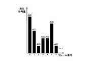
- FIG. 9 is an explanatory diagram showing an example of a generated code amount for each image frame in a bit stream obtained by compressing and encoding a certain video.
- FIG. 10 is an explanatory diagram showing an example of the transition of the buffer occupancy in the virtual buffer simulating the reception buffer that receives the bit stream.
- the virtual buffer has a predetermined buffer size Bmax.
- the virtual buffer continues to increase the buffer occupancy of the virtual buffer at a predetermined bit rate R until a predetermined time Dinit is reached.
- the virtual buffer subtracts the code amount A (0) of the data group corresponding to the image frame with frame number 0 from the buffer occupation amount.
- This process corresponds to a process of supplying the data group of the frame from the reception buffer to the decoder in the actual video decoding apparatus. If this time is t (0) and the playback time interval between video frames of the video is f ⁇ ⁇ , the virtual buffer again has a predetermined bit rate R until the time t (1) defined by the following equation (1) is reached. Continue to increase the buffer occupancy of the virtual buffer. Then, the video encoding device subtracts the code amount A (1) of the data group corresponding to the image frame of frame number 1 from the buffer occupancy amount at time t (1).
- the virtual buffer subsequently increases the code amount A (k) of the data group corresponding to the image frame of frame number k at time t (k) while increasing the buffer occupancy of the virtual buffer at a predetermined bit rate R. Repeat the process of subtracting from the occupancy.
- the bit rate R, buffer size Bmax, and decoding start delay time Dinit are generally determined before the start of the encoding process according to image quality requirements, delay requirements, transmission path characteristics, etc. It is transmitted to the decoding device. Further, instead of the decoding start delay time Dinit, an initial buffer occupation amount Binit obtained by the following equation (2) may be transmitted.
- a transmission method for example, in accordance with the rules described in Non-Patent Document 2, there is a method of encoding as auxiliary information and multiplexing and transmitting the bitstream.
- FIG. 11 is a block diagram showing an example of the configuration of a general video encoding apparatus that performs encoding while monitoring the operation of the virtual buffer in this way.
- the video encoding apparatus shown in FIG. 11 includes a video encoder 911, a virtual buffer 912, and a multiplexer 913.
- the video encoder 911 generates a video bitstream by encoding each image frame constituting the input data (input video) while monitoring the operation of the virtual buffer 912. Then, the video encoder 911 supplies the generated video bitstream to the multiplexer 913 and supplies the generated code amount to the virtual buffer 912.
- the virtual buffer 912 calculates the buffer occupation amount at each time based on the buffer setting information including the buffer size and the delay amount and the generated code amount supplied from the video encoder 911.
- the virtual buffer 912 feeds back the calculation result to the video encoder 911.
- the multiplexer 913 encodes the buffer setting information as auxiliary information, multiplexes it with the video bit stream supplied from the video encoder 911, and outputs it as a bit stream.
- the video decoding apparatus can decode the bit stream transmitted at a predetermined bit rate without failure and output it as video.
- a delay corresponding to Dinit shown in FIG. 10 occurs during video transmission.
- the delay associated with video transmission becomes a factor that impairs the interactivity, for example, the reception channel cannot be switched smoothly in television broadcasting. Therefore, in a system that performs transmission through the transmission buffer and the reception buffer, the transmission delay is required to be as small as possible.
- the video encoding apparatus stores the compression-encoded input video in the storage and then transmits it to the video decoding apparatus via the buffer.
- the video decoding apparatus transmits the received data in real time.
- a transmission delay is determined by an operation setting determined in advance before starting the encoding process, for example, Dinit. That is, in such a system, since the transmission delay is determined by the operation setting at the time when the bit stream is generated by the video encoding device and stored in the storage device, the transmission delay cannot be further reduced. .
- Patent Document 1 For example.
- some margin is provided for the upper and lower limits of the upper limit value (for example, Bmax shown in FIG. 10) and the lower limit value (for example, 0) of the virtual buffer, and the buffer occupancy exceeds the upper limit margin. Control to avoid falling below the lower margin.
- the buffer occupation amount does not reach the upper and lower limits of the buffer. Further, depending on the characteristics of the input video, the fluctuation of the generated code amount per unit time in the bit stream is small, and as a result, the buffer occupancy amount may not reach the predetermined upper and lower limits of the buffer. For this reason, the technique described in Patent Document 1 has a problem that the size of the buffer required for transmission is wasted or a wasteful transmission delay occurs.
- Patent Document 2 describes a technique for re-compressing a bit stream obtained by compressing a video.
- Patent Document 2 describes a technique for re-compressing a bit stream obtained by compressing a video.
- the amount of calculation associated with the process increases because a video decoding process and a compression encoding process are required.
- image quality degradation occurs by recompressing a once compressed video.
- the present invention provides a time series that can reduce the buffer size and transmission delay required for transmission without performing recompression processing on the time series data when transmitting compression-coded time series data.
- An object is to provide a data encoding device, a time-series data re-encoding device, a time-series data encoding method, a time-series data re-encoding method, a time-series data encoding program, and a time-series data re-encoding program.
- the time-series data encoding apparatus stores time-series data encoding means for compressing and encoding time-series data to generate an encoded bitstream, and a virtual decoder buffer defined according to the encoding method.
- a virtual buffer for calculating the transition of the amount of data to be processed, a buffer usage analysis means for analyzing the transition of the amount of accumulated data, and resetting parameters indicating the buffer size and the amount of accumulated data at a predetermined time of the buffer, and And a multiplexing unit that multiplexes the encoded bit stream generated by the sequence data encoding unit and the parameter reset by the buffer usage amount analyzing unit.
- a time-series data re-encoding device includes a demultiplexing means for demultiplexing a coded bitstream including operating parameters of a virtual decoder buffer defined according to a coding method, and demultiplexing Code amount detecting means for calculating the data amount per predetermined time in the time-series data bit stream, a virtual buffer for calculating the transition of the data amount accumulated in the buffer, and analyzing the transition of the accumulated data amount,
- the buffer usage analysis means for resetting the parameter indicating the size of the buffer and the amount of stored data at a predetermined time of the buffer, the demultiplexed time-series data bitstream, and the parameter reset by the buffer usage analysis means are multiplexed. And multiplexing means.
- the time-series data encoding method generates a coded bitstream by compressing and encoding time-series data, and changes the amount of data accumulated in a virtual decoder buffer defined according to the encoding method. Calculate and analyze the transition of the accumulated data amount, reset the buffer size and the parameter indicating the accumulated data amount at the predetermined time of the buffer, and multiplex the generated encoded bitstream and the reset parameter It is characterized by becoming.
- the time-series data re-encoding method demultiplexes the encoded bitstream including the operation parameter of the virtual decoder buffer defined according to the encoding method, and demultiplexes the time-series data Calculates the amount of data per bit time in the bitstream, calculates the transition of the amount of data stored in the virtual decoder buffer, analyzes the transition of the amount of stored data, stores the buffer size and the buffer at a predetermined time A parameter indicating the data amount is reset, and the demultiplexed time-series data bit stream and the reset parameter are multiplexed.
- a time-series data encoding program is stored in a buffer of a virtual decoder defined according to a process for generating a coded bitstream by compressing and encoding time-series data in a computer.
- the time-series data re-encoding program is a program for demultiplexing an encoded bitstream including operating parameters of a virtual decoder buffer defined according to an encoding method, and demultiplexing. Processing for calculating the amount of data per predetermined time in the time-series data bit stream, processing for calculating the transition of the amount of data stored in the buffer of the virtual decoder, and analyzing the transition of the amount of stored data, A process for resetting a parameter indicating the size of the buffer and an amount of stored data at a predetermined time, and a process for multiplexing the demultiplexed time-series data bitstream and the reset parameter.
- the present invention when transmitting compression-coded time-series data, it is possible to reduce the buffer size and transmission delay required for transmission without performing re-compression processing for the time-series data.
- Embodiment 1 FIG. A first embodiment of the present invention will be described below with reference to the drawings.
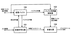
- FIG. 1 is a block diagram showing a configuration of a video encoding apparatus according to the first embodiment.
- the video encoding device of the present embodiment includes a video encoder 101, a virtual buffer 102, a buffer usage amount analyzer 103, and a multiplexer 104.
- the video encoding device of the present embodiment is different from the video encoding device shown in FIG. 11 in that it includes a buffer usage amount analyzer 103 that analyzes the buffer usage amount and calculates optimum buffer setting information.
- the video encoder 101 encodes each image frame constituting the input video while monitoring the operation of the virtual buffer 102 to generate a video bitstream.
- the video encoder 101 supplies the generated video bitstream to the multiplexer 104 and supplies the generated code amount to the virtual buffer 102.
- the virtual buffer 102 determines each time according to the initial buffer setting information including the buffer size and the delay amount of the virtual decoder buffer defined according to the encoding method, and the generated code amount supplied from the video encoder 101.
- the amount of data stored in the buffer (accumulated data amount), that is, the buffer occupation amount at each time is calculated.
- the virtual buffer 102 feeds back the calculation result to the video encoder 101 and also supplies it to the buffer usage analyzer 103.
- the buffer usage analyzer 103 monitors the operation of the virtual buffer 102 based on the data indicating the calculation result of the buffer occupancy supplied from the virtual buffer 102. Then, the buffer usage amount analyzer 103 calculates the minimum buffer size and the minimum delay amount necessary for actual transmission from the transition of the buffer occupation amount. The buffer usage analyzer 103 supplies the calculation result to the multiplexer 104 as optimum buffer setting information.
- the multiplexer 104 encodes the optimum buffer setting information supplied from the buffer usage analyzer 103, multiplexes it with the video bitstream supplied from the video encoder 101, and outputs it as a bitstream.
- the video encoding apparatus can configure the bit stream so as to reduce the buffer size and transmission delay required for transmission.
- the reason is that the buffer usage analyzer 103 analyzes the transition of the buffer occupancy received from the virtual buffer 102 to calculate optimum buffer setting information, and the multiplexer 104 determines the optimum buffer setting information as the initial buffer setting. This is because it is multiplexed into a bit stream instead of information and transmitted to a video transmission device and a video decoding device. That is, the video transmission device and the video decoding device can recognize the minimum buffer size and delay amount necessary for transmission.
- the video encoder 101, the virtual buffer 102, the buffer usage analyzer 103, and the multiplexer 104 are realized by a computer that operates according to a time-series data encoding program, for example.
- the CPU reads the time-series data encoding program and operates as the video encoder 101, the virtual buffer 102, the buffer usage analyzer 103, and the multiplexer 104 according to the program.
- the video encoder 101, the virtual buffer 102, the buffer usage amount analyzer 103, and the multiplexer 104 may be realized by separate hardware.
- FIG. 2 is a flowchart showing optimum buffer setting information calculation processing of the buffer usage analyzer according to the first embodiment.
- the buffer usage analyzer 103 initializes the maximum buffer occupancy Bmax ', the minimum buffer occupancy Bmin', the buffer occupancy BOC ', and the frame number k (step S201).
- the buffer usage analyzer 103 sets 0 as the initial value for the maximum buffer occupancy Bmax ′ and sets the buffer size Bmax in the initial buffer setting information as the initial value for the minimum buffer occupancy Bmin ′ ′.
- the buffer usage amount analyzer 103 sets the initial buffer occupancy Binit in the initial buffer setting information as an initial value in the buffer occupancy BOC, and sets 0 as the initial value in the frame number k.
- the buffer usage amount analyzer 103 subtracts the code amount of the frame k having the frame number k from the current buffer occupation amount (step S202).
- the buffer occupation amount is updated by the following equation (3).
- the buffer usage analyzer 103 determines whether or not the current buffer occupancy BOC ⁇ ⁇ is less than the minimum buffer occupancy Bmin ′ (step S203). When the current buffer occupancy BOC is less than the minimum buffer occupancy Bmin ′ (YES in step S203), the buffer usage analyzer 103 proceeds to the processing in step S204. If the current buffer occupancy BOC is not less than the minimum buffer occupancy Bmin ′ (NO in step S203), the process proceeds to step S205.
- step S204 the buffer usage amount analyzer 103 updates the value of the minimum buffer occupation amount Bmin ′ ′ with the current buffer occupation amount BOC ′.
- step S205 the buffer usage analyzer 103 determines whether or not the current frame is the last frame to be processed. If the current frame is the last frame to be processed (YES in step S205), the process proceeds to step S209. If the current frame is not the last frame to be processed (NO in step S205), the process proceeds to step S206.
- step S206 the buffer usage analyzer 103 increments the frame number by one. Further, the buffer usage amount analyzer 103 obtains the buffer occupation amount immediately before the code amount subtraction process of the next frame.
- the buffer occupancy is updated by the following equation (4).
- the buffer usage amount analyzer 103 determines whether or not the current buffer occupancy BOC exceeds the maximum buffer occupancy Bmax′max (step S207). If the current buffer occupancy BOC exceeds the maximum buffer occupancy Bmax ′ (YES in step S207), the process proceeds to step S208. If the current buffer occupancy BOC does not exceed the maximum buffer occupancy Bmax ′ (NO in step S207), the process returns to step S202.
- step S208 the buffer usage amount analyzer 103 updates the value of the maximum buffer occupation amount Bmax ′ with the current buffer occupation amount BOC ⁇ . After the buffer usage analyzer 103 executes the process of step S208, the process returns to the process of step S202.
- step S209 the buffer usage analyzer 103 calculates optimum buffer setting information.
- the buffer size, the initial buffer occupation amount, and the decoding start delay time in the optimum buffer setting information are Bmax_real, Binit_real, and Dinit_real, respectively.
- Bmax_real, Binit_real, and Dinit_real are calculated by the following equations (5), (6), and (7), respectively.
- Bmax_real Bmax ⁇ -Bmin ⁇ (5)
- Binit_real Binit-Bmin ⁇ (6)
- Dinit_real Binit_real / R (7)
- the buffer usage amount analyzer 103 calculates the optimum buffer setting information, the buffer usage amount analysis process is terminated.
- the video encoding device uses the optimum buffer setting information calculated by the buffer usage amount analyzer 103 as auxiliary information in accordance with, for example, the rules described in Non-Patent Document 2. It may be encoded and multiplexed into a bit stream for transmission. Further, the multiplexer 104 may perform the multiplexing for each GOP that is a random access cycle, or may be performed in arbitrary units.
- the buffer usage analyzer 103 analyzes the transition of the buffer occupancy received from the virtual buffer 102 to calculate optimum buffer setting information, and the multiplexer 104
- the buffer setting information is multiplexed into a bit stream instead of the initial buffer setting information and transmitted to the video transmission device and the video decoding device.
- the video encoding apparatus can make the video transmission apparatus and the video decoding apparatus recognize the minimum buffer size and delay amount necessary for transmission. Accordingly, when transmitting the generated bit stream to the video decoding device via the buffer, the video encoding device reduces the buffer size and transmission delay required for transmission without performing recompression processing on the video data. be able to.
- the buffer usage amount analyzer 103 calculates the optimum buffer setting information only once. However, the buffer usage analyzer 103 may calculate the optimum buffer information a plurality of times. For example, the buffer usage amount analyzer 103 may calculate the buffer occupancy amount and the decoding start delay time for each random access cycle, and output them as optimum buffer setting information.
- the buffer usage amount analyzer 103 calculates the optimum buffer setting information by using both the maximum value and the minimum value of the buffer occupation amount.
- the buffer usage amount analyzer 103 may calculate the optimum buffer setting information using, for example, one of the maximum value and the minimum value of the buffer occupation amount.
- the buffer usage analyzer 103 calculates the transition of the buffer occupancy with the bit rate R and the frame time interval f as predetermined constants.
- the bit rate R and the frame time interval f may be variable values that change with time.
- the buffer usage amount analyzer 103 analyzes the buffer occupancy amount for each image frame and calculates the optimum buffer setting information.
- the buffer usage amount analyzer 103 may analyze the buffer occupancy amount in units of partial images such as slices obtained by dividing the image frame, and calculate optimum buffer setting information.
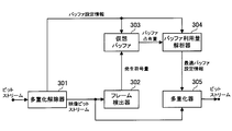
- FIG. 3 is a block diagram showing the configuration of the video re-encoding device of the second embodiment.
- the video re-encoding device of this embodiment includes a demultiplexer 301, a frame detector 302, a virtual buffer 303, a buffer usage analyzer 304, and a multiplexer 305.
- a characteristic point of the video re-encoding device of the present embodiment is that it includes a buffer usage amount analyzer 304 that analyzes the buffer usage amount and calculates optimum buffer setting information.
- the demultiplexer 301 receives the multiplexed bit stream and demultiplexes the bit stream. That is, the demultiplexer 301 separates the multiplexed video bitstream and buffer setting information. Then, the demultiplexer 301 supplies the video bit stream to the frame detector 302 and the multiplexer 305. Further, the demultiplexer 301 supplies the buffer setting information to the virtual buffer 303 and the buffer usage amount analyzer 304.
- the frame detector 302 scans the video bit stream supplied from the demultiplexer 301 and detects a data group constituting the image frame and a break between the data groups. Then, the frame detector 302 calculates the code amount for each image frame and supplies the calculation result (generated code amount) to the virtual buffer 303.
- the virtual buffer 303 calculates the buffer occupation amount at each time based on the buffer setting information including the buffer size and the delay amount supplied from the demultiplexer 301 and the generated code amount supplied from the frame detector 302. And supplied to the buffer usage analyzer 304.
- the buffer usage analyzer 304 monitors the operation of the virtual buffer 303 based on the data indicating the calculation result of the buffer occupancy supplied from the virtual buffer 303, and calculates optimum buffer setting information from the transition of the buffer occupancy. Then, the buffer usage analyzer 304 supplies the optimum buffer setting information calculated to the multiplexer 305.
- buffer usage amount analysis processing in the buffer usage amount analyzer 304 is the same as the processing in the buffer usage amount analyzer 103 of the video encoding device of the first embodiment, and a description thereof will be omitted.
- the multiplexer 305 encodes the optimum buffer setting information supplied from the buffer usage analyzer 304 and multiplexes it with the video bitstream supplied from the demultiplexer 301.
- the multiplexer 305 outputs a video bit stream in which the optimum buffer setting information is multiplexed.
- the video re-encoding device can reconfigure the bit stream so as to reduce the buffer size and transmission delay required for transmission without decoding and re-compressing the video bit stream.
- the reason is that the buffer usage analyzer 304 analyzes the transition of the buffer occupancy received from the virtual buffer 303 to calculate optimum buffer setting information, and the multiplexer 305 receives the buffer setting given to the input bitstream. This is because the optimum buffer setting information is multiplexed into the bit stream instead of the information and transmitted to the video transmission device and the video decoding device. That is, the video transmission device and the video decoding device can recognize the minimum buffer size and delay amount necessary for transmission.
- the demultiplexer 301, the frame detector 302, the virtual buffer 303, the buffer usage amount analyzer 304, and the multiplexer 305 are realized by a computer that operates according to a time-series data re-encoding program, for example.
- the CPU reads the time-series data re-encoding program, and operates as a demultiplexer 301, a frame detector 302, a virtual buffer 303, a buffer usage analyzer 304, and a multiplexer 305 according to the program.
- the demultiplexer 301, the frame detector 302, the virtual buffer 303, the buffer usage amount analyzer 304, and the multiplexer 305 may be realized by separate hardware.
- the video re-encoding device according to the present invention can be suitably applied to, for example, the video transmission system shown in FIG. That is, in the video transmission system shown in FIG. 8, the video re-encoding device is arranged between the storage device and the video transmission device, so that the bit stream stored in the storage device is supplied to the video transmission device. Can be re-encoded and optimized.
- each embodiment described so far shows a preferred embodiment of the present invention, and the present invention is not limited to the above embodiment.
- the present invention can be implemented in various forms without departing from the gist of the present invention.
- the present invention is not limited to transmission of video data, but can be applied to transmission of audio and other arbitrary time-series data.
- the present invention can be configured by hardware, but can also be realized by a computer program.
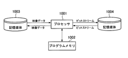
- FIG. 4 is a block diagram showing an example of the configuration of an information processing system to which the present invention is applied.
- the information processing system illustrated in FIG. 4 includes a processor 1001, a program memory 1002, a storage medium 1003, and a storage medium 1004.
- the storage medium 1003 and the storage medium 1004 may be separate storage media or the same storage medium with different storage areas.
- a magnetic storage medium such as a hard disk can be used as the storage medium.
- the processor 1001 that operates with the computer program (time-series data encoding program or time-series data re-encoding program) stored in the program memory 1002 realizes the same functions and operations as the above-described embodiments. .
- the configuration of the information processing system to which the present invention is applied is not limited to the configuration shown in FIG. 4, and the present invention can also realize only a part of the functions of the above-described embodiment by a computer program. It is.
- FIG. 5 is a block diagram showing the minimum configuration of the time-series data encoding apparatus according to the present invention.
- FIG. 6 is a block diagram showing the minimum configuration of the time-series data re-encoding device according to the present invention.
- the time-series data encoding apparatus includes time-series data encoding means 11 (in the video encoding apparatus shown in FIG. 1) that compresses and encodes time-series data to generate an encoded bit stream. And a virtual buffer 12 for calculating the transition of the amount of data stored in the buffer of the virtual decoder defined according to the encoding method (virtual in the video encoding device shown in FIG. 1). And buffer usage amount analyzing means 13 (the video code shown in FIG. 1) for analyzing the transition of the accumulated data amount and resetting the parameters indicating the buffer size and the accumulated data amount at a predetermined time.
- the time-series data encoding device can make the video transmission device and the video decoding device recognize the minimum buffer size and delay amount necessary for transmission, for example. Therefore, when transmitting the generated bit stream to a video decoding device or the like via a buffer, the time-series data encoding device does not perform re-compression processing on the time-series data and transmits the buffer size and transmission required for transmission. Delay can be reduced.
- the buffer usage amount analyzing means 13 uses the maximum value and the minimum value of the data amount stored in the buffer of the virtual decoder defined according to the encoding method, and uses the buffer size and the buffer at a predetermined time. A parameter indicating the accumulated data amount may be reset. According to such a configuration, for example, the accumulated data amount (buffer occupancy) of the virtual buffer can be calculated and output as optimum buffer setting information for each random access cycle. Therefore, the buffer size and transmission delay required for transmission can be reduced.
- the buffer usage amount analyzing unit 13 subtracts the minimum value from the maximum value of the data amount stored in the buffer of the virtual decoder defined according to the encoding method, and obtains the value after resetting the buffer size.
- the value after the resetting of the accumulated data amount at the predetermined time of the buffer may be calculated by subtracting the minimum value from the accumulated data amount at the predetermined time of the buffer. According to such a configuration, it is possible to accurately calculate the parameter indicating the size of the virtual buffer and the amount of data stored in the virtual buffer at a predetermined time. Therefore, the buffer size and transmission delay required for transmission can be surely reduced.
- the time-series data re-encoding device performs multiplexing to demultiplex an encoded bitstream including operating parameters of a virtual decoder buffer defined according to an encoding method.
- Decoding means 21 corresponding to demultiplexer 301 in the video re-encoding device shown in FIG. 3
- code amount detection means 22 for calculating the data amount per predetermined time in the demultiplexed time-series data bit stream (Corresponding to the frame detector 302 in the video re-encoding device shown in FIG. 3) and a virtual buffer 23 (virtual buffer 303 in the video re-encoding device shown in FIG. 3) for calculating the transition of the amount of data stored in the buffer.
- the buffer usage amount analyzing means 24 (corresponding to the buffer usage amount analyzer 304 in the video re-encoding device shown in FIG. 3), the demultiplexed time-series data bit stream, and the buffer usage amount analyzing means 24.
- multiplexing means 25 (corresponding to the multiplexer 305 in the video re-encoding apparatus shown in FIG. 3) for multiplexing the reset parameters.
- the bit stream can be reconfigured so as to reduce the buffer size and transmission delay required for transmission without decoding and recompressing the time-series data bit stream.
- the buffer usage amount analyzing unit 24 uses the maximum value and the minimum value of the data amount stored in the buffer of the virtual decoder defined according to the encoding method, and uses the buffer size and the buffer at a predetermined time. A parameter indicating the accumulated data amount may be reset. According to such a configuration, for example, the accumulated data amount (buffer occupancy) of the virtual buffer can be calculated and output as optimum buffer setting information for each random access cycle. Therefore, the buffer size and transmission delay required for transmission can be reduced.
- the buffer usage amount analyzing means 24 is defined according to the encoding method, where A is the maximum value of the data amount stored in the buffer of the virtual decoder specified according to the encoding method, and B is the minimum value.
- A is the maximum value of the data amount stored in the buffer of the virtual decoder specified according to the encoding method
- B is the minimum value.
- Time-series data encoding means for compressing and encoding time-series data to generate an encoded bit stream, and transition of the amount of data stored in a virtual decoder buffer defined according to the encoding method A virtual buffer to be calculated; buffer utilization amount analyzing means for analyzing a transition of the accumulated data amount and resetting a parameter indicating the size of the buffer and the accumulated data amount at a predetermined time of the buffer; and the time-series data code
- a time-series data encoding apparatus comprising: a multiplexing unit that multiplexes the encoded bit stream generated by the encoding unit and the parameter reset by the buffer usage amount analyzing unit.
- the buffer usage amount analyzing means uses the maximum value and the minimum value of the data amount stored in the buffer of the virtual decoder defined according to the encoding method, and uses the buffer size and the buffer size.
- the buffer usage amount analyzing means sets A as the maximum value of the data amount stored in the buffer of the virtual decoder defined according to the encoding method, and B as the minimum value, according to the encoding method.
- the size of the specified virtual decoder buffer is C and the accumulated data amount at the predetermined time of the buffer is D
- the time-series data encoding device when transmitting the generated bit stream through the buffer, the time-series data encoding device does not perform recompression processing on the video data and transmits the buffer size and transmission necessary for transmission. Delay can be reduced.
- Demultiplexing means for demultiplexing the encoded bitstream including the operation parameter of the virtual decoder buffer defined according to the encoding method, and the demultiplexed time-series data bitstream
- a code amount detecting means for calculating a data amount per predetermined time; a virtual buffer for calculating a transition of the amount of data accumulated in the buffer; and a transition of the accumulated data amount of the buffer, and analyzing the size of the buffer and
- a buffer usage amount analyzing means for resetting a parameter indicating a stored data amount at a predetermined time of the buffer, a demultiplexed time-series data bit stream, and a parameter reset by the buffer usage amount analyzing means are multiplexed. And a time-series data re-encoding device.
- the buffer usage amount analyzing means uses the maximum value and the minimum value of the data amount stored in the virtual decoder buffer defined according to the encoding method, and uses the buffer size and the buffer size.
- the buffer usage amount analyzing means sets A as the maximum value of the data amount stored in the buffer of the virtual decoder defined according to the encoding method, and B as the minimum value, according to the encoding method.
- A the maximum value of the data amount stored in the buffer of the virtual decoder defined according to the encoding method
- B the minimum value, according to the encoding method.
- the bitstream can be reconfigured so as to reduce the buffer size and transmission delay required for transmission without decoding and recompressing the video bitstream.
- a time series data is compression-encoded to generate an encoded bit stream, a transition of the amount of data stored in a virtual decoder buffer defined according to the encoding method is calculated, and the stored data amount The parameter indicating the size of the buffer and the amount of data stored in the buffer at a predetermined time is reset, and the generated encoded bitstream and the reset parameter are multiplexed.
- a time-series data encoding method characterized by the above.
- the maximum value of the amount of data stored in the buffer of the virtual decoder specified according to the encoding method is A, the minimum value is B, and the virtual decoder specified according to the encoding method
- the size of the buffer is C and the amount of stored data at the predetermined time of the buffer is D
- the buffer at the predetermined time is calculated.
- Decoding of the encoded bit stream including the operation parameters of the virtual decoder buffer defined according to the encoding method is performed, and data at predetermined time intervals in the demultiplexed time-series data bit stream Calculating the amount of data, calculating the transition of the amount of data stored in the buffer of the virtual decoder, analyzing the transition of the amount of stored data, and indicating the size of the buffer and the amount of data stored in the buffer at a predetermined time
- the maximum value of the amount of data stored in the buffer of the virtual decoder specified according to the encoding method is A, the minimum value is B, and the virtual decoder specified according to the encoding method
- the size of the buffer is C and the amount of stored data at the predetermined time of the buffer is D
- the buffer at the predetermined time is calculated.
- a maximum value of data stored in a buffer of a virtual decoder defined according to an encoding method is set to A and a minimum value is set to B, and a virtual value specified according to the encoding method.
- the time-series data encoding program according to appendix 18, which executes a process of calculating a value after resetting the accumulated data amount at a predetermined time based on the formula F DB.
- a process of demultiplexing an encoded bitstream including operation parameters of a virtual decoder buffer defined according to an encoding method, and a demultiplexed time-series data bitstream A process for calculating a data amount for each predetermined time; a process for calculating a transition of the amount of data stored in the buffer of the virtual decoder; and a transition of the amount of stored data is analyzed to determine the size of the buffer and the buffer A time series for executing a process for resetting a parameter indicating an accumulated data amount at a predetermined time, a process for multiplexing the demultiplexed time series data bitstream, and the reset parameter Data re-encoding program.
- a maximum value of data stored in a buffer of a virtual decoder defined according to an encoding method is set to A and a minimum value is set to B, and a virtual value specified according to the encoding method
- the time-series data re-encoding program according to appendix 22, which executes a process of calculating a value after resetting the amount of accumulated data at a predetermined time based on the formula F DB.
- Time series data encoding means 12 Virtual buffer 13 Buffer utilization amount analysis means 14 Multiplexing means 21 Demultiplexing means 22 Code amount detection means 23 Virtual buffer 24 Buffer utilization amount analysis means 25 Multiplexing means 101,911 Video encoder 102, 912 Virtual buffer 103 Buffer usage analyzer 104, 913 Multiplexer 301 Demultiplexer 302 Frame detector 303 Virtual buffer 304 Buffer usage analyzer 305 Multiplexer 710 Video encoding transmission device 711 Encoder 712 Transmission buffer 720, 840 Video decoding device 721, 841 Reception buffer 722, 842 Decoder 810 Video encoding device 820 Storage device 830 Video transmission device 831 Transmission device 832 Transmission buffer 1001 Processor 1002 Program memory 10 03, 1004 Storage media
Landscapes
- Engineering & Computer Science (AREA)
- Multimedia (AREA)
- Signal Processing (AREA)
- General Engineering & Computer Science (AREA)
- Computing Systems (AREA)
- Theoretical Computer Science (AREA)
- Compression Or Coding Systems Of Tv Signals (AREA)
Abstract
Description
以下、本発明の第1の実施形態を図面を参照して説明する。
A first embodiment of the present invention will be described below with reference to the drawings.
Binit_real = Binit - Bmin´ ・・・式(6)
Dinit_real = Binit_real / R ・・・式(7) Bmax_real = Bmax´-Bmin´ (5)
Binit_real = Binit-Bmin´ (6)
Dinit_real = Binit_real / R (7)
以下、本発明の第2の実施形態を図面を参照して説明する。
Hereinafter, a second embodiment of the present invention will be described with reference to the drawings.
12 仮想バッファ
13 バッファ利用量解析手段
14 多重化手段
21 多重化解除手段
22 符号量検出手段
23 仮想バッファ
24 バッファ利用量解析手段
25 多重化手段
101、911 映像符号化器
102、912 仮想バッファ
103 バッファ利用量解析器
104、913 多重化器
301 多重化解除器
302 フレーム検出器
303 仮想バッファ
304 バッファ利用量解析器
305 多重化器
710 映像符号化送出装置
711 符号化器
712 送信バッファ
720、840 映像復号装置
721、841 受信バッファ
722、842 復号器
810 映像符号化装置
820 記憶装置
830 映像送出装置
831 送出器
832 送信バッファ
1001 プロセッサ
1002 プログラムメモリ
1003、1004 記憶媒体 DESCRIPTION OF
Claims (10)
- 時系列データを圧縮符号化して符号化ビットストリームを生成する時系列データ符号化手段と、
符号化方式に応じて規定される仮想復号器のバッファに蓄積されるデータ量の推移を算出する仮想バッファと、
前記蓄積データ量の推移を解析して、前記バッファのサイズおよび前記バッファの所定時刻における蓄積データ量を示すパラメータを再設定するバッファ利用量解析手段と、
前記時系列データ符号化手段が生成した符号化ビットストリームと、前記バッファ利用量解析手段が再設定したパラメータとを多重化する多重化手段とを備える
ことを特徴とする時系列データ符号化装置。 Time-series data encoding means for compressing and encoding time-series data to generate an encoded bitstream;
A virtual buffer for calculating the transition of the amount of data accumulated in the buffer of the virtual decoder defined according to the encoding method;
Analyzing the transition of the accumulated data amount, and resetting a parameter indicating the size of the buffer and the accumulated data amount at a predetermined time of the buffer;
A time-series data encoding apparatus comprising: a multiplexing unit that multiplexes the encoded bit stream generated by the time-series data encoding unit and the parameter reset by the buffer usage amount analysis unit. - バッファ利用量解析手段は、符号化方式に応じて規定される仮想復号器のバッファに蓄積されるデータ量の最大値と最小値とを用いて、前記バッファのサイズおよび前記バッファの所定時刻における蓄積データ量を示すパラメータを再設定する
請求項1に記載の時系列データ符号化装置。 The buffer usage amount analyzing means uses the maximum value and the minimum value of the data amount stored in the virtual decoder buffer defined according to the encoding method, and stores the buffer size and the buffer at a predetermined time. The time-series data encoding device according to claim 1, wherein a parameter indicating a data amount is reset. - バッファ利用量解析手段は、符号化方式に応じて規定される仮想復号器のバッファに蓄積されるデータ量の最大値をA、最小値をBとし、前記符号化方式に応じて規定される仮想復号器のバッファのサイズをC、前記バッファの所定時刻における蓄積データ量をDとするとき、前記バッファのサイズの再設定後の値を式E=A-Bに基づいて算出し、前記バッファの所定時刻における蓄積データ量の再設定後の値を式F=D-Bに基づいて算出する
請求項2に記載の時系列データ符号化装置。 The buffer usage amount analyzing means sets the maximum value of the data amount stored in the buffer of the virtual decoder specified according to the encoding method as A and the minimum value as B, and determines the virtual amount specified according to the encoding method. When the size of the buffer of the decoder is C and the amount of data stored in the buffer at a predetermined time is D, a value after resetting the size of the buffer is calculated based on the equation E = AB, The time-series data encoding device according to claim 2, wherein a value after resetting of the accumulated data amount at a predetermined time is calculated based on an equation F = DB. - 符号化方式に応じて規定される仮想復号器のバッファの動作パラメータを含む符号化ビットストリームの多重化を解除する多重化解除手段と、
多重化解除された時系列データビットストリームにおける所定時間ごとのデータ量を算出する符号量検出手段と、
前記バッファに蓄積されるデータ量の推移を算出する仮想バッファと、
前記蓄積データ量の推移を解析して、前記バッファのサイズおよび前記バッファの所定時刻における蓄積データ量を示すパラメータを再設定するバッファ利用量解析手段と、
前記多重化解除された時系列データビットストリームと、前記バッファ利用量解析手段が再設定したパラメータとを多重化する多重化手段とを備える
ことを特徴とする時系列データ再符号化装置。 Demultiplexing means for demultiplexing the encoded bitstream including the operation parameters of the virtual decoder buffer defined according to the encoding scheme;
Code amount detection means for calculating a data amount per predetermined time in the demultiplexed time-series data bitstream;
A virtual buffer for calculating the transition of the amount of data accumulated in the buffer;
Analyzing the transition of the accumulated data amount, and resetting a parameter indicating the size of the buffer and the accumulated data amount at a predetermined time of the buffer;
A time-series data re-encoding apparatus comprising: a multiplexing unit that multiplexes the demultiplexed time-series data bit stream and the parameter reset by the buffer usage amount analyzing unit. - バッファ利用量解析手段は、符号化方式に応じて規定される仮想復号器のバッファに蓄積されるデータ量の最大値と最小値とを用いて、前記バッファのサイズおよび前記バッファの所定時刻における蓄積データ量を示すパラメータを再設定する
請求項4に記載の時系列データ再符号化装置。 The buffer usage amount analyzing means uses the maximum value and the minimum value of the data amount stored in the virtual decoder buffer defined according to the encoding method, and stores the buffer size and the buffer at a predetermined time. The time-series data re-encoding device according to claim 4, wherein a parameter indicating a data amount is reset. - バッファ利用量解析手段は、符号化方式に応じて規定される仮想復号器のバッファに蓄積されるデータ量の最大値をA、最小値をBとし、前記符号化方式に応じて規定される仮想復号器のバッファのサイズをC、前記バッファの所定時刻における蓄積データ量をDとするとき、前記バッファのサイズの再設定後の値を式E=A-Bに基づいて算出し、前記バッファの所定時刻における蓄積データ量の再設定後の値を式F=D-Bに基づいて算出する
請求項5に記載の時系列データ再符号化装置。 The buffer usage amount analyzing means sets the maximum value of the data amount stored in the buffer of the virtual decoder specified according to the encoding method as A and the minimum value as B, and determines the virtual amount specified according to the encoding method. When the size of the buffer of the decoder is C and the amount of data stored in the buffer at a predetermined time is D, a value after resetting the size of the buffer is calculated based on the equation E = AB, 6. The time-series data re-encoding device according to claim 5, wherein a value after resetting the accumulated data amount at a predetermined time is calculated based on an equation F = DB. - 時系列データを圧縮符号化して符号化ビットストリームを生成し、
符号化方式に応じて規定される仮想復号器のバッファに蓄積されるデータ量の推移を算出し、
前記蓄積データ量の推移を解析して、前記バッファのサイズおよび前記バッファの所定時刻における蓄積データ量を示すパラメータを再設定し、
前記生成された符号化ビットストリームと、前記再設定されたパラメータとを多重化する
ことを特徴とする時系列データ符号化方法。 Time-series data is compression-encoded to generate an encoded bitstream;
Calculate the transition of the amount of data stored in the virtual decoder buffer defined according to the encoding method,
Analyzing the transition of the accumulated data amount, reset the parameter indicating the size of the buffer and the accumulated data amount at a predetermined time of the buffer,
The time-series data encoding method, wherein the generated encoded bit stream and the reset parameter are multiplexed. - 符号化方式に応じて規定される仮想復号器のバッファの動作パラメータを含む符号化ビットストリームの多重化を解除し、
多重化解除された時系列データビットストリームにおける所定時間ごとのデータ量を算出し、
前記仮想復号器のバッファに蓄積されるデータ量の推移を算出し、
前記蓄積データ量の推移を解析して、前記バッファのサイズおよび前記バッファの所定時刻における蓄積データ量を示すパラメータを再設定し、
前記多重化解除された時系列データビットストリームと、前記再設定されたパラメータとを多重化する
ことを特徴とする時系列データ再符号化方法。 Demultiplexing the encoded bitstream including the virtual decoder buffer operating parameters defined according to the encoding scheme;
Calculate the amount of data per predetermined time in the demultiplexed time-series data bitstream,
Calculating the transition of the amount of data stored in the buffer of the virtual decoder;
Analyzing the transition of the accumulated data amount, reset the parameter indicating the size of the buffer and the accumulated data amount at a predetermined time of the buffer,
The time-series data re-encoding method, wherein the de-multiplexed time-series data bit stream and the reset parameter are multiplexed. - コンピュータに、
時系列データを圧縮符号化して符号化ビットストリームを生成する処理と、
符号化方式に応じて規定される仮想復号器のバッファに蓄積されるデータ量の推移を算出する処理と、
前記蓄積データ量の推移を解析して、前記バッファのサイズおよび前記バッファの所定時刻における蓄積データ量を示すパラメータを再設定する処理と、
前記生成された符号化ビットストリームと、前記再設定されたパラメータとを多重化するする処理とを実行させる
ための時系列データ符号化プログラム。 On the computer,
A process for compressing and encoding time-series data to generate an encoded bitstream;
A process of calculating the transition of the amount of data accumulated in the buffer of the virtual decoder defined according to the encoding method;
Analyzing the transition of the accumulated data amount, and resetting a parameter indicating the size of the buffer and the accumulated data amount at a predetermined time of the buffer;
A time-series data encoding program for executing a process of multiplexing the generated encoded bitstream and the reset parameter. - コンピュータに、
符号化方式に応じて規定される仮想復号器のバッファの動作パラメータを含む符号化ビットストリームの多重化を解除する処理と、
多重化解除された時系列データビットストリームにおける所定時間ごとのデータ量を算出する処理と、
前記仮想復号器のバッファに蓄積されるデータ量の推移を算出する処理と、
前記蓄積データ量の推移を解析して、前記バッファのサイズおよび前記バッファの所定時刻における蓄積データ量を示すパラメータを再設定する処理と、
前記多重化解除された時系列データビットストリームと、前記再設定されたパラメータとを多重化する処理とを実行させる
ための時系列データ再符号化プログラム。 On the computer,
A process of demultiplexing the encoded bitstream including the operating parameters of the virtual decoder buffer defined according to the encoding scheme;
A process of calculating a data amount per predetermined time in the demultiplexed time-series data bitstream;
A process for calculating the transition of the amount of data stored in the buffer of the virtual decoder;
Analyzing the transition of the accumulated data amount, and resetting a parameter indicating the size of the buffer and the accumulated data amount at a predetermined time of the buffer;
A time-series data re-encoding program for executing a process of multiplexing the demultiplexed time-series data bit stream and the reset parameter.
Priority Applications (2)
| Application Number | Priority Date | Filing Date | Title |
|---|---|---|---|
| US14/888,505 US10021432B2 (en) | 2013-06-06 | 2014-04-11 | Time series data encoding apparatus, method, and program, and time series data re-encoding apparatus, method, and program |
| JP2015521266A JP6344386B2 (en) | 2013-06-06 | 2014-04-11 | Time-series data encoding apparatus, method and program, and time-series data re-encoding apparatus, method and program |
Applications Claiming Priority (2)
| Application Number | Priority Date | Filing Date | Title |
|---|---|---|---|
| JP2013-119853 | 2013-06-06 | ||
| JP2013119853 | 2013-06-06 |
Publications (1)
| Publication Number | Publication Date |
|---|---|
| WO2014196113A1 true WO2014196113A1 (en) | 2014-12-11 |
Family
ID=52007777
Family Applications (1)
| Application Number | Title | Priority Date | Filing Date |
|---|---|---|---|
| PCT/JP2014/002084 WO2014196113A1 (en) | 2013-06-06 | 2014-04-11 | Time series data encoding apparatus, method, and program, and time series data re-encoding apparatus, method, and program |
Country Status (3)
| Country | Link |
|---|---|
| US (1) | US10021432B2 (en) |
| JP (1) | JP6344386B2 (en) |
| WO (1) | WO2014196113A1 (en) |
Cited By (1)
| Publication number | Priority date | Publication date | Assignee | Title |
|---|---|---|---|---|
| JP2018082251A (en) * | 2016-11-14 | 2018-05-24 | キヤノン株式会社 | Imaging device, image processing method, and program |
Families Citing this family (2)
| Publication number | Priority date | Publication date | Assignee | Title |
|---|---|---|---|---|
| CN108153483B (en) * | 2016-12-06 | 2021-04-20 | 南京南瑞继保电气有限公司 | Time sequence data compression method based on attribute grouping |
| WO2019199147A1 (en) * | 2018-04-13 | 2019-10-17 | Samsung Electronics Co., Ltd. | Method and system for handling data path creation in wireless network system |
Citations (4)
| Publication number | Priority date | Publication date | Assignee | Title |
|---|---|---|---|---|
| JPH11355230A (en) * | 1998-06-10 | 1999-12-24 | Victor Co Of Japan Ltd | Encoding device |
| JP2006519517A (en) * | 2003-03-31 | 2006-08-24 | シャープ株式会社 | Video encoder and method for encoding video |
| JP2010278815A (en) * | 2009-05-29 | 2010-12-09 | Victor Co Of Japan Ltd | Method, device and program for editing video compressed and encoded data |
| JP2011211691A (en) * | 2010-03-11 | 2011-10-20 | Sony Corp | Information processing apparatus, information processing method and program |
Family Cites Families (5)
| Publication number | Priority date | Publication date | Assignee | Title |
|---|---|---|---|---|
| JP4264535B2 (en) | 2003-02-04 | 2009-05-20 | ソニー株式会社 | Image processing apparatus and method, recording medium, and program |
| JP4023451B2 (en) | 2004-02-02 | 2007-12-19 | 日本電気株式会社 | Compressed video re-encoding device and compressed video re-encoding method |
| US7359324B1 (en) * | 2004-03-09 | 2008-04-15 | Nortel Networks Limited | Adaptive jitter buffer control |
| EP1814334A4 (en) * | 2005-10-12 | 2010-04-28 | Nec Corp | Moving image conversion method, moving image conversion device, moving image conversion system, server device, and program |
| US20110299589A1 (en) * | 2010-06-04 | 2011-12-08 | Apple Inc. | Rate control in video communication via virtual transmission buffer |
-
2014
- 2014-04-11 JP JP2015521266A patent/JP6344386B2/en not_active Expired - Fee Related
- 2014-04-11 US US14/888,505 patent/US10021432B2/en not_active Expired - Fee Related
- 2014-04-11 WO PCT/JP2014/002084 patent/WO2014196113A1/en active Application Filing
Patent Citations (4)
| Publication number | Priority date | Publication date | Assignee | Title |
|---|---|---|---|---|
| JPH11355230A (en) * | 1998-06-10 | 1999-12-24 | Victor Co Of Japan Ltd | Encoding device |
| JP2006519517A (en) * | 2003-03-31 | 2006-08-24 | シャープ株式会社 | Video encoder and method for encoding video |
| JP2010278815A (en) * | 2009-05-29 | 2010-12-09 | Victor Co Of Japan Ltd | Method, device and program for editing video compressed and encoded data |
| JP2011211691A (en) * | 2010-03-11 | 2011-10-20 | Sony Corp | Information processing apparatus, information processing method and program |
Cited By (1)
| Publication number | Priority date | Publication date | Assignee | Title |
|---|---|---|---|---|
| JP2018082251A (en) * | 2016-11-14 | 2018-05-24 | キヤノン株式会社 | Imaging device, image processing method, and program |
Also Published As
| Publication number | Publication date |
|---|---|
| US10021432B2 (en) | 2018-07-10 |
| JPWO2014196113A1 (en) | 2017-02-23 |
| US20160094862A1 (en) | 2016-03-31 |
| JP6344386B2 (en) | 2018-06-20 |
Similar Documents
| Publication | Publication Date | Title |
|---|---|---|
| JP6312704B2 (en) | Syntax and semantics for buffering information that simplify video splicing | |
| TWI606722B (en) | Method, system, and computer-readable media for reducing latency in video encoding and decoding | |
| US8654849B2 (en) | Integrated transcoding | |
| US5677969A (en) | Method, rate controller, and system for preventing overflow and underflow of a decoder buffer in a video compression system | |
| EP1942594B1 (en) | Method and apparatus for statistically multiplexing services | |
| US7333515B1 (en) | Methods and apparatus to improve statistical remultiplexer performance by use of predictive techniques | |
| US9992456B2 (en) | Method and apparatus for hypothetical reference decoder conformance error detection | |
| JP4358215B2 (en) | Video encoding apparatus and method | |
| US20060239563A1 (en) | Method and device for compressed domain video editing | |
| US20150312601A1 (en) | Methods and apparatuses including a statistical multiplexer with multiple channel rate control | |
| KR102618101B1 (en) | Optimization of encoding operations when creating buffer-constrained versions of media titles | |
| US10412424B2 (en) | Multi-channel variable bit-rate video compression | |
| US7173947B1 (en) | Methods and apparatus to evaluate statistical remultiplexer performance | |
| US20140328384A1 (en) | Methods and apparatuses including a statistical multiplexer with global rate control | |
| WO2009066284A3 (en) | A method and system for compressing digital video streams | |
| US8311104B2 (en) | Information processing apparatus and method, recording medium, and program | |
| US20110310955A1 (en) | Method and system for repetition based adaptive video compression | |
| JP6344386B2 (en) | Time-series data encoding apparatus, method and program, and time-series data re-encoding apparatus, method and program | |
| US20090185620A1 (en) | Video encoding apparatus and method for the same | |
| JPWO2008053557A1 (en) | Moving image re-encoding device, moving image re-encoding method, moving image re-encoding program, and recording medium storing moving image re-encoding program | |
| JP2009246489A (en) | Video-signal switching apparatus | |
| JP4878052B2 (en) | Video code amount control method, video encoding device, video code amount control program, and recording medium therefor | |
| JP2016149770A (en) | Minimization system of streaming latency and method of using the same | |
| JP2010136041A (en) | Method, apparatus and program for transmitting encoded stream, and recording medium for the program | |
| AU678927C (en) | Method, rate controller, and system for preventing overflow and underflow of a decoder buffer |
Legal Events
| Date | Code | Title | Description |
|---|---|---|---|
| 121 | Ep: the epo has been informed by wipo that ep was designated in this application |
Ref document number: 14808246 Country of ref document: EP Kind code of ref document: A1 |
|
| ENP | Entry into the national phase |
Ref document number: 2015521266 Country of ref document: JP Kind code of ref document: A |
|
| WWE | Wipo information: entry into national phase |
Ref document number: 14888505 Country of ref document: US |
|
| NENP | Non-entry into the national phase |
Ref country code: DE |
|
| 122 | Ep: pct application non-entry in european phase |
Ref document number: 14808246 Country of ref document: EP Kind code of ref document: A1 |