WO2014192466A1 - 超音波診断装置、超音波診断装置の音線信号生成方法、及び超音波診断装置の音線信号生成プログラム - Google Patents
超音波診断装置、超音波診断装置の音線信号生成方法、及び超音波診断装置の音線信号生成プログラム Download PDFInfo
- Publication number
- WO2014192466A1 WO2014192466A1 PCT/JP2014/061319 JP2014061319W WO2014192466A1 WO 2014192466 A1 WO2014192466 A1 WO 2014192466A1 JP 2014061319 W JP2014061319 W JP 2014061319W WO 2014192466 A1 WO2014192466 A1 WO 2014192466A1
- Authority
- WO
- WIPO (PCT)
- Prior art keywords
- ultrasonic
- element data
- phase
- elements
- unit
- Prior art date
- Legal status (The legal status is an assumption and is not a legal conclusion. Google has not performed a legal analysis and makes no representation as to the accuracy of the status listed.)
- Ceased
Links
Images


Classifications
-
- G—PHYSICS
- G01—MEASURING; TESTING
- G01S—RADIO DIRECTION-FINDING; RADIO NAVIGATION; DETERMINING DISTANCE OR VELOCITY BY USE OF RADIO WAVES; LOCATING OR PRESENCE-DETECTING BY USE OF THE REFLECTION OR RERADIATION OF RADIO WAVES; ANALOGOUS ARRANGEMENTS USING OTHER WAVES
- G01S7/00—Details of systems according to groups G01S13/00, G01S15/00, G01S17/00
- G01S7/52—Details of systems according to groups G01S13/00, G01S15/00, G01S17/00 of systems according to group G01S15/00
- G01S7/52017—Details of systems according to groups G01S13/00, G01S15/00, G01S17/00 of systems according to group G01S15/00 particularly adapted to short-range imaging
- G01S7/52046—Techniques for image enhancement involving transmitter or receiver
- G01S7/52047—Techniques for image enhancement involving transmitter or receiver for elimination of side lobes or of grating lobes; for increasing resolving power
-
- A—HUMAN NECESSITIES
- A61—MEDICAL OR VETERINARY SCIENCE; HYGIENE
- A61B—DIAGNOSIS; SURGERY; IDENTIFICATION
- A61B8/00—Diagnosis using ultrasonic, sonic or infrasonic waves
- A61B8/13—Tomography
- A61B8/14—Echo-tomography
-
- A—HUMAN NECESSITIES
- A61—MEDICAL OR VETERINARY SCIENCE; HYGIENE
- A61B—DIAGNOSIS; SURGERY; IDENTIFICATION
- A61B8/00—Diagnosis using ultrasonic, sonic or infrasonic waves
- A61B8/44—Constructional features of the ultrasonic, sonic or infrasonic diagnostic device
- A61B8/4483—Constructional features of the ultrasonic, sonic or infrasonic diagnostic device characterised by features of the ultrasound transducer
- A61B8/4488—Constructional features of the ultrasonic, sonic or infrasonic diagnostic device characterised by features of the ultrasound transducer the transducer being a phased array
-
- G—PHYSICS
- G01—MEASURING; TESTING
- G01S—RADIO DIRECTION-FINDING; RADIO NAVIGATION; DETERMINING DISTANCE OR VELOCITY BY USE OF RADIO WAVES; LOCATING OR PRESENCE-DETECTING BY USE OF THE REFLECTION OR RERADIATION OF RADIO WAVES; ANALOGOUS ARRANGEMENTS USING OTHER WAVES
- G01S15/00—Systems using the reflection or reradiation of acoustic waves, e.g. sonar systems
- G01S15/88—Sonar systems specially adapted for specific applications
- G01S15/89—Sonar systems specially adapted for specific applications for mapping or imaging
- G01S15/8906—Short-range imaging systems; Acoustic microscope systems using pulse-echo techniques
- G01S15/8909—Short-range imaging systems; Acoustic microscope systems using pulse-echo techniques using a static transducer configuration
- G01S15/8915—Short-range imaging systems; Acoustic microscope systems using pulse-echo techniques using a static transducer configuration using a transducer array
- G01S15/8927—Short-range imaging systems; Acoustic microscope systems using pulse-echo techniques using a static transducer configuration using a transducer array using simultaneously or sequentially two or more subarrays or subapertures
-
- G—PHYSICS
- G01—MEASURING; TESTING
- G01S—RADIO DIRECTION-FINDING; RADIO NAVIGATION; DETERMINING DISTANCE OR VELOCITY BY USE OF RADIO WAVES; LOCATING OR PRESENCE-DETECTING BY USE OF THE REFLECTION OR RERADIATION OF RADIO WAVES; ANALOGOUS ARRANGEMENTS USING OTHER WAVES
- G01S7/00—Details of systems according to groups G01S13/00, G01S15/00, G01S17/00
- G01S7/52—Details of systems according to groups G01S13/00, G01S15/00, G01S17/00 of systems according to group G01S15/00
- G01S7/52017—Details of systems according to groups G01S13/00, G01S15/00, G01S17/00 of systems according to group G01S15/00 particularly adapted to short-range imaging
- G01S7/52023—Details of receivers
- G01S7/52036—Details of receivers using analysis of echo signal for target characterisation
- G01S7/52038—Details of receivers using analysis of echo signal for target characterisation involving non-linear properties of the propagation medium or of the reflective target
-
- G—PHYSICS
- G10—MUSICAL INSTRUMENTS; ACOUSTICS
- G10K—SOUND-PRODUCING DEVICES; METHODS OR DEVICES FOR PROTECTING AGAINST, OR FOR DAMPING, NOISE OR OTHER ACOUSTIC WAVES IN GENERAL; ACOUSTICS NOT OTHERWISE PROVIDED FOR
- G10K11/00—Methods or devices for transmitting, conducting or directing sound in general; Methods or devices for protecting against, or for damping, noise or other acoustic waves in general
- G10K11/18—Methods or devices for transmitting, conducting or directing sound
- G10K11/26—Sound-focusing or directing, e.g. scanning
- G10K11/34—Sound-focusing or directing, e.g. scanning using electrical steering of transducer arrays, e.g. beam steering
- G10K11/341—Circuits therefor
- G10K11/346—Circuits therefor using phase variation
-
- A—HUMAN NECESSITIES
- A61—MEDICAL OR VETERINARY SCIENCE; HYGIENE
- A61B—DIAGNOSIS; SURGERY; IDENTIFICATION
- A61B8/00—Diagnosis using ultrasonic, sonic or infrasonic waves
- A61B8/52—Devices using data or image processing specially adapted for diagnosis using ultrasonic, sonic or infrasonic waves
- A61B8/5207—Devices using data or image processing specially adapted for diagnosis using ultrasonic, sonic or infrasonic waves involving processing of raw data to produce diagnostic data, e.g. for generating an image
Definitions
- the present invention relates to an ultrasonic diagnostic apparatus, a sound ray signal generation method for an ultrasonic diagnostic apparatus, and a sound ray signal generation program for an ultrasonic diagnostic apparatus.
- Non-Patent Document 1 Nobuyuki Kiura, “Harmonic Imaging”, Journal of Japanese Society of Radiological Technology, P350-356) and Patent Document 1 (Japanese Patent Laid-Open No. 58) are techniques for reducing side lobes and improving azimuth resolution in ultrasonic diagnosis. -44372)) has been proposed.
- Non-Patent Document 1 proposes a technique for improving the drawbacks of the filter method that separates the basic component and the second harmonic component by the second harmonic detection filter and extracts only the second harmonic component and visualizes it. ing. Specifically, two ultrasonic transmissions in which the phases of the first transmission wave and the second transmission wave are reversed are performed in the same direction. The fundamental wave component of the two received waves by the two transmitted waves is inverted in phase, but the second harmonic component is in phase, so the fundamental wave component and the second harmonic component of the two received waves are respectively By adding, the fundamental wave component is removed to obtain a doubled second harmonic component. Thereby, the fall of the distance resolution which is a fault of the filter method can be improved.
- Patent Document 1 proposes a technique for improving azimuth resolution and contrast resolution by sequentially adding received signals obtained by transmission and reception of a plurality of different apertures.
- Non-Patent Document 1 since imaging is performed by two ultrasonic transmissions, the number of frames is halved and the time resolution is reduced.
- the present invention has been made in consideration of the above facts, an ultrasonic diagnostic apparatus capable of obtaining a high-quality ultrasonic image by reducing side lobes, a sound ray signal generation method of the ultrasonic diagnostic apparatus, and A sound ray signal generation program for an ultrasonic diagnostic apparatus is provided.
- the radiation signal processing apparatus of the present invention opens a probe including a plurality of elements that generate ultrasonic waves and receive ultrasonic waves reflected from an inspection target, and a predetermined number of element groups of the probes. As described above, an ultrasonic wave is transmitted from a plurality of elements so that a positive phase opening and a negative phase opening corresponding to the positive phase opening are determined in advance and the phase is inverted to transmit an ultrasonic beam to the inspection object.
- a transmitter for transmitting an ultrasonic echo signal generated by the interaction between the ultrasonic beam and the inspection object via a plurality of elements of the probe, and at least two in the inspection object In each of the overlapping target regions, an ultrasonic beam is transmitted from an opening having a different phase and centered on a different element, and at least two or more overlapping targets in the inspection object are transmitted by the ultrasonic beam.
- An element data holding unit for holding two or more element data including reception time information in each element, generated by receiving an ultrasonic echo signal generated for each region by the receiving unit, and held in the element data holding unit
- a generation unit that generates a sound ray signal in one scanning line by superimposing each element data.
- the probe includes a plurality of elements that generate ultrasonic waves and receive ultrasonic waves reflected on the inspection target.
- the transmitting unit sets a predetermined number of element groups of the probe as openings, sets a positive phase opening and a negative phase opening in advance, inverts the phase, and transmits a plurality of ultrasonic beams to the inspection target. Ultrasound is transmitted from the element. That is, an ultrasonic wave having an inverted phase is transmitted from the positive phase opening and the negative phase opening.
- the receiving unit receives an ultrasonic echo signal generated by the interaction between the ultrasonic beam and the inspection object via a plurality of elements of the probe.
- the element data holding unit At least two or more overlapping target regions in the inspection object are transmitted by the transmitting unit from the openings centered on different elements at different phases and transmitted by the transmitting unit.
- the generation unit generates a sound ray signal in one scanning line by superimposing the element data held in the element data holding unit.
- the generation unit by adding and superimposing element data at the positive phase aperture and element data at the negative phase, only the second harmonic component is extracted, so a sound ray signal in which the influence of side lobes is suppressed is generated. can do. Therefore, it is possible to reduce the side lobes and obtain a high-quality ultrasonic image.
- the transmission unit sets the number of openings to be an even number, sets openings at positions symmetrical with respect to the scanning line as positive-phase openings and negative-phase openings, and inverts the phase from each of the openings for ultrasonic waves. You may make it transmit an ultrasonic wave from a some element so that a beam may be transmitted.
- the number of openings is an odd number
- ultrasonic waves are transmitted from a plurality of elements so as to transmit an ultrasonic beam by inverting the phase from each of the positive phase openings and the negative phase openings,
- the sound ray signal may be generated by superimposing the element data.
- the generation unit includes a delay time calculation unit that calculates a delay time of two or more element data, and a probe that receives the delay time calculated by the delay time calculation unit, reception time information, and an ultrasonic echo signal. Based on the position of each element, two or more unprocessed element data are overlapped by matching the time on the reception time and the absolute position of the element of the probe from which the ultrasonic echo signal is received. And a superposition processing unit to be combined.
- the transmission unit may transmit ultrasonic waves from a plurality of elements so that the positive phase opening and the negative phase opening are adjacent to each other and transmit the ultrasonic beam alternately.
- the sound ray signal generation method of the ultrasonic diagnostic apparatus of the present invention generates a predetermined number of elements of a probe including a plurality of elements that generate ultrasonic waves and receive ultrasonic waves reflected on an inspection target.
- the ultrasonic wave is transmitted from a plurality of elements so as to transmit an ultrasonic beam to an object to be inspected by predetermining a positive-phase opening and a negative-phase opening corresponding to the positive-phase opening in a group and inverting the phase.
- Transmitting at least two or more overlapping target areas in the inspection object by transmitting a ultrasonic beam from an opening having a different phase and centering on a different element, and transmitting the ultrasonic beam and the inspection object
- a receiving unit that receives an ultrasonic echo signal generated by the interaction with the object via a plurality of elements of the probe
- Receiving the generated ultrasonic echo signal holding two or more element data including reception time information in each element generated by receiving the ultrasonic echo signal in the element data holding unit, and holding the element data And superimposing each element data held in the unit to generate a sound ray signal in one scanning line.
- a predetermined number of elements of a probe including a plurality of elements that generate ultrasonic waves and receive ultrasonic waves reflected on the inspection target
- a transmission unit that transmits ultrasonic waves from a plurality of elements so as to transmit an ultrasonic beam to the inspection object by inverting the phase with the positive phase opening and the negative phase opening being determined in advance as a group.
- An ultrasonic beam is transmitted from an opening centered on a different element at a different phase for each of at least two overlapping target regions in the object. In other words, ultrasonic waves whose phases are reversed are transmitted from the positive phase opening and the negative phase opening.
- the receiving unit that receives the ultrasonic echo signal generated by the interaction between the ultrasonic beam and the inspection object through the plurality of elements of the probe.
- An ultrasonic echo signal generated for each overlapping target region is received.
- each element data held in the element data holding unit is superposed to generate a sound ray signal in one scanning line.
- element data at the positive phase aperture and element data at the negative phase only the second harmonic component is extracted, so a sound ray signal in which the influence of side lobes is suppressed is generated. can do. Therefore, it is possible to reduce the side lobes and obtain a high-quality ultrasonic image.
- the number of openings is an even number
- the openings at positions symmetrical with respect to the scanning line are made into positive-phase openings and negative-phase openings, and the ultrasonic beam is obtained by reversing the phase from each of the openings in the transmitter.
- the ultrasonic waves may be transmitted from a plurality of elements so as to transmit.
- ultrasonic waves are transmitted from a plurality of elements so as to transmit an ultrasonic beam by inverting the phase from each of the positive phase openings and the negative phase openings of the transmission unit having an odd number of openings, and the element data is superimposed.
- the element data held in the element data holding unit is superimposed on the basis of the reception time information and the coefficient predetermined for each opening so that the sound pressure from the target point is the same, and the sound ray A signal may be generated.
- the generation of the sound ray signal includes calculating the delay time of two or more element data, and calculating the delay time, the reception time information, and the position of the element of the probe from which the ultrasonic echo signal is received. And superimposing two or more raw element data on the reception time and matching the absolute position of the element of the probe from which the ultrasonic echo signal was received, May be further provided.
- ultrasonic waves may be transmitted from a plurality of elements such that an ultrasonic beam is alternately transmitted with a positive phase opening and a negative phase opening adjacent to each other.
- the sound ray signal generation program of the ultrasonic diagnostic apparatus of the present invention generates a predetermined number of elements of a probe including a plurality of elements that generate ultrasonic waves and receive ultrasonic waves reflected on the inspection target.
- the ultrasonic wave is transmitted from a plurality of elements so as to transmit an ultrasonic beam to an object to be inspected by predetermining a positive-phase opening and a negative-phase opening corresponding to the positive-phase opening in a group and inverting the phase.
- Transmitting at least two or more overlapping target areas in the inspection object by transmitting a ultrasonic beam from an opening having a different phase and centering on a different element, and transmitting the ultrasonic beam and the inspection object
- At least two overlapping target areas in the inspection object are received by a receiving unit that receives an ultrasonic echo signal generated by the interaction with the object via a plurality of elements of the probe.
- a computer is caused to execute a process including superimposing each element data held in the data holding unit to generate a sound ray signal in one scanning line.
- a predetermined number of elements of a probe including a plurality of elements that generate ultrasonic waves and receive ultrasonic waves reflected on the inspection target
- a transmission unit that transmits ultrasonic waves from a plurality of elements so as to transmit an ultrasonic beam to the inspection object by inverting the phase with the positive phase opening and the negative phase opening being determined in advance as a group.
- An ultrasonic beam is transmitted from an opening centered on a different element at a different phase for each of at least two overlapping target regions in the object. In other words, ultrasonic waves whose phases are reversed are transmitted from the positive phase opening and the negative phase opening.
- the receiving unit that receives the ultrasonic echo signal generated by the interaction between the ultrasonic beam and the inspection object via the plurality of elements of the probe.
- An ultrasonic echo signal generated for each target area is received.
- each element data held in the element data holding unit is superposed to generate a sound ray signal in one scanning line.
- element data at the positive phase aperture and element data at the negative phase only the second harmonic component is extracted, so a sound ray signal in which the influence of side lobes is suppressed is generated. can do. Therefore, it is possible to reduce the side lobes and obtain a high-quality ultrasonic image.
- the number of openings is an even number
- the openings at positions symmetrical with respect to the scanning line are made into positive-phase openings and negative-phase openings, and the ultrasonic beam is obtained by reversing the phase from each of the openings in the transmitter.
- the ultrasonic waves may be transmitted from a plurality of elements so as to transmit.
- ultrasonic waves are transmitted from a plurality of elements so as to transmit an ultrasonic beam by inverting the phase from each of the positive phase openings and the negative phase openings of the transmission unit having an odd number of openings, and the element data is superimposed.
- the element data held in the element data holding unit is superimposed on the basis of the reception time information and the coefficient predetermined for each opening so that the sound pressure from the target point is the same, and the sound ray A signal may be generated.
- the generation of the sound ray signal includes calculating the delay time of two or more element data, and calculating the delay time, the reception time information, and the position of the element of the probe from which the ultrasonic echo signal is received. And superimposing two or more raw element data on the reception time and matching the absolute position of the element of the probe from which the ultrasonic echo signal was received, May be further provided.
- ultrasonic waves may be transmitted from a plurality of elements such that an ultrasonic beam is alternately transmitted with a positive phase opening and a negative phase opening adjacent to each other.
- the side lobe can be reduced and a high-quality ultrasonic image can be obtained.
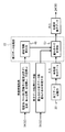
- FIG. 1 is a block diagram showing a schematic configuration of an ultrasonic diagnostic apparatus according to the present embodiment. It is a block diagram which shows the structure of an element data processing part.
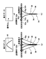
- (A) And (c) is a figure which shows the case where an ideal ultrasonic beam is each transmitted from the element right above the reflective point of a test object, and the element which is not right above, (b) and (d) are respectively It is a figure which shows the element data obtained.
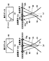
- (A) And (c) is a figure which shows the case where an actual ultrasonic beam is each transmitted from the element right above the reflective point of a subject, and the element which is not right above, (b) and (d) are obtained respectively. It is a figure which shows the element data to be obtained.
- (A) And (b) is a figure which shows the distance of the transmission path
- (C) And (d) is a figure which shows the element data obtained by a some element, and those delay times, respectively.
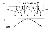
- (A), (b), and (c), and (d), (e), and (f) are element data obtained from a plurality of elements in the case of a true signal and a ghost, It is a figure which shows the overlay state of delay time and element data,
- (g) And (h) is a figure which shows the overlay state of the element data corresponding to a some element, and its result, respectively.
- FIG. 1 is a block diagram showing a schematic configuration of the ultrasonic diagnostic apparatus according to the present embodiment.
- the ultrasonic diagnostic apparatus 10 includes an ultrasonic probe 12, a transmission unit 14 and a reception unit 16 connected to the ultrasonic probe 12, an A / D conversion unit 18, and an element data storage unit 20.
- An element data processing unit 22 an image generation unit 24, a display control unit 26, a display unit 28, a control unit 30, an operation unit 32, and a storage unit 34.
- the ultrasonic probe 12 has a probe 36 used in a normal ultrasonic diagnostic apparatus.
- the probe 36 has a plurality of elements arranged in a one-dimensional or two-dimensional array, that is, ultrasonic transducers. These ultrasonic transducers transmit an ultrasonic beam to the subject according to a drive signal supplied from the transmission unit 14 and receive an ultrasonic echo from the subject when imaging an ultrasonic image of the subject. To output a received signal.
- each of a predetermined number of ultrasonic transducers constituting a set of the plurality of ultrasonic transducers of the probe 36 generates each component of one ultrasonic beam, and a predetermined number of sets.
- the ultrasonic transducer generates one ultrasonic beam to be transmitted to the subject.
- Each ultrasonic transducer is, for example, a piezoelectric ceramic represented by PZT (lead zirconate titanate), a polymer piezoelectric element represented by PVDF (polyvinylidene fluoride), or PMN-PT (magnesium niobate / lead titanate). It is constituted by an element (vibrator) in which electrodes are formed on both ends of a piezoelectric body made of a piezoelectric single crystal represented by a solid solution). That is, the probe 36 is a transducer array in which a plurality of transducers are arranged in a one-dimensional or two-dimensional array as a plurality of ultrasonic elements.
- PZT lead zirconate titanate
- PVDF polymer piezoelectric element represented by PVDF (polyvinylidene fluoride)
- PMN-PT magnesium niobate / lead titanate
- the probe 36 is a transducer array in which a plurality of
- each transducer When a pulsed or continuous wave voltage is applied to the electrodes of such a vibrator, the piezoelectric material expands and contracts, and pulse or continuous wave ultrasonic waves are generated from the respective vibrators, and the synthesis of these ultrasonic waves. As a result, an ultrasonic beam is formed.
- each transducer generates an electric signal by expanding and contracting by receiving propagating ultrasonic waves, and these electric signals are output as ultrasonic reception signals.
- the transmission unit 14 includes, for example, a plurality of pulsars, and based on a transmission delay pattern selected according to a control signal from the control unit 30, a set of a predetermined number of ultrasonic transducers ( Hereinafter, the adjusted drive signals are grouped by adjusting the delay amount of the drive signal of each ultrasonic element so that the ultrasonic wave transmitted from the ultrasonic element forms one ultrasonic beam. Supply to multiple ultrasonic elements.
- the receiving unit 16 receives, from the subject, an ultrasonic echo generated by the interaction between the ultrasonic beam and the subject by each ultrasonic element of the probe 36 in accordance with a control signal from the control unit 30. Then, the reception signal, that is, the analog element signal for each ultrasonic element is amplified and output, and the amplified analog element signal is supplied to the A / D converter 18.
- the A / D conversion unit 18 is connected to the receiving unit 16 and converts the analog element signal supplied from the receiving unit 16 into digital element data.
- the A / D conversion unit 18 supplies the A / D converted digital element data to the element data storage unit 20.
- the element data storage unit 20 sequentially stores the digital element data output from the A / D conversion unit 18.
- the element data storage unit 20 receives information on the frame rate input from the control unit 30 (for example, parameters indicating the depth of the reflection position of the ultrasonic wave, the density of the scanning line, and the field width) from the above-described digital element data (hereinafter referred to as the “element data”) , Simply referred to as element data) and stored.
- the element data storage unit 20 inspects at least two or more target regions that overlap in a target region on two-dimensional or higher position coordinates in accordance with a control signal from the control unit 30, the two or more target regions every time, two or more element data generated for each of two or more target areas from the ultrasonic echoes received by the receiving unit 16 are stored and held.
- the element data stored and held in the element data storage unit 20 is two or more element data including reception time information in each element.
- the element data processing unit 22 is based on the control by the control unit 30 and generates two or more element data (hereinafter referred to as unprocessed element data) generated for each of two or more target regions stored and held by the element data storage unit 20. ) Are overlapped with each other on the reception time to generate post-overlay element data (hereinafter referred to as processed element data). Details of the element data processing unit 22 will be described later.
- the image generation unit 24 generates a sound ray signal (reception data) from the processed element data supplied from the element data processing unit 22 under the control of the control unit 30, and generates an ultrasonic image from the sound ray signal.
- the image generation unit 24 includes a phasing addition unit 38, a detection processing unit 40, a DSC 42, an image creation unit 44, and an image memory 46.
- the phasing addition unit 38 selects one reception delay pattern from a plurality of reception delay patterns stored in advance according to the reception direction set in the control unit 30, and based on the selected reception delay pattern Thus, reception focus processing is performed by adding the respective delays to the element data. By this reception focus processing, reception data (sound ray signal) in which the focus of the ultrasonic echo is narrowed is generated. In addition, the phasing addition unit 38 supplies the generated reception data to the detection processing unit 40.
- the detection processing unit 40 corrects attenuation by distance according to the depth of the reflection position of the ultrasonic wave on the reception data generated by the phasing addition unit 38, and then performs envelope detection processing to perform detection.
- B-mode image data that is tomographic image information related to the tissue in the specimen is generated.
- a DSC (digital scan converter) 42 converts the B-mode image data generated by the detection processing unit 40 into image data according to a normal television signal scanning method (raster conversion).
- the image creating unit 44 performs various necessary image processing such as gradation processing on the B-mode image data input from the DSC 42 to create B-mode image data for use in inspection and display.
- the display B-mode image data is output to the display control unit 26 for display or stored in the image memory 46.
- the image memory 46 temporarily stores the inspection B-mode image data created by the image creation unit 44.
- the inspection B-mode image data stored in the image memory 46 is read to the display control unit 26 for display on the display unit 28 as necessary.
- the display control unit 26 causes the display unit 28 to display an ultrasonic image based on the inspection B-mode image signal subjected to image processing by the image creation unit 44.
- the display unit 28 includes a display device such as an LCD, for example, and displays an ultrasonic image under the control of the display control unit 26.
- the control unit 30 controls each unit of the ultrasonic diagnostic apparatus 10 based on a command input from the operation unit 32 by the operator.
- the control unit 30 receives various information by the operator via the operation unit 32, particularly information necessary for calculating the delay time used in the phasing addition unit 38 of the element data processing unit 22 and the image generation unit 24, and element data.
- the above-described various information input from the operation unit 32 is transmitted as necessary to the transmission unit 14, the reception unit 16, and the element data storage.
- the data is supplied to each unit such as the unit 20, the element data processing unit 22, the image generation unit 24, and the display control unit 26.
- the operation unit 32 is for an operator to perform an input operation, and includes a keyboard, a mouse, a trackball, a touch panel, and the like.
- the operation unit 32 is used by the operator for various types of information, in particular, a plurality of ultrasonic elements of the probe 36 of the probe 12 used for calculating the delay time described above, the sound speed of the examination target region of the subject, Provided with an input device for inputting and operating information regarding the focal position of the ultrasonic beam, the transmission aperture and the reception aperture of the probe 36, and information regarding element data processing such as the number of overlapping element data and the overlay processing method ing.
- the storage unit 34 receives various information input from the operation unit 32, in particular, information on the probe 12, the sound speed, the focal position, the transmission aperture and the reception aperture, the transmission phase information for each transmission aperture, and superposition element data.
- Information related to element data processing such as the number and overlay processing method, etc.
- a control unit 30 such as a transmission unit 14, a reception unit 16, an element data storage unit 20, an element data processing unit 22, an image generation unit 24, and a display control unit 26
- a recording medium such as a ROM or a DVD-ROM can be used.
- the element data processing unit 22, the phasing addition unit 38, the detection processing unit 40, the DSC 42, the image creation unit 44, and the display control unit 26 are based on the CPU and an operation program for causing the CPU to perform various processes. It may be configured, or may be a hardware configuration such as a digital circuit.
- FIG. 2 is a block diagram illustrating a schematic configuration of the element data processing unit.
- the element data processing unit 22 includes a delay time calculation unit 48 and an overlay processing unit 50.
- the delay time calculation unit 48 is input by operating the operation unit 32, or is input by operating the operation unit 32 and stored in the storage unit 34. Information regarding the ultrasonic element, the sound velocity of the examination target region of the subject, the focal position of the ultrasonic beam, the transmission aperture and the reception aperture of the probe 36, and the like are acquired in advance. Then, the delay time calculation unit 48 forms an ultrasonic beam and transmits the ultrasonic element (transmission element) of the transmission aperture, and receives an ultrasonic echo from the subject by the ultrasonic beam. Based on the geometric arrangement with the sound wave element, the delay time of the element data received by each ultrasonic element of the reception aperture is calculated.
- the superimposition processing unit 50 inputs the number of element data to be superimposed and the superposition input by operating the operation unit 32 or input by operating the operation unit 32 and stored in the storage unit 34. Based on information relating to element data processing such as a processing method, two or more unprocessed element data generated for each of two or more target areas stored and held by the element data storage unit 20 are read. Then, the superimposition processing unit 50 sets two or more unprocessed element data on the reception time based on the delay time calculated by the delay time calculation unit 48 and the reception time information of each element, and Then, the absolute positions of the elements of the probe from which the ultrasonic echoes are received are aligned and superimposed to generate processed element data.
- element data processing such as a processing method
- an ultrasonic beam (hereinafter simply referred to as a transmission beam) is transmitted from a transmission ultrasonic element (hereinafter simply referred to as a transmission element) of the probe 36 of the ultrasonic probe 12 to the subject, and a mutual relationship with the subject is obtained.
- a transmission ultrasonic element hereinafter simply referred to as a transmission element
- element data it is obtained by the transmission beam from the transmitting element and the receiving element. The relationship with element data will be described.
- ultrasonic echoes are received using seven ultrasonic elements (hereinafter also simply referred to as elements) 52a to 52g and 52b to 52h as receiving elements, respectively. Get element data.
- elements seven ultrasonic elements (hereinafter also simply referred to as elements) 52a to 52g and 52b to 52h as receiving elements, respectively.
- Get element data In an ideal case where the transmission beam 56 to be transmitted to the inspection target area including the reflection point 54 is ideally narrowed to an element interval or less, the reflection point 54 in the inspection target area as shown in FIG.
- the focus of the transmitting beam 56 58 is on a straight line connecting the element 54d and the reflection point 54, and the transmission beam 56 is transmitted to the reflection point 54, so that an ultrasonic echo reflected from the reflection point 54 is generated.
- the ultrasonic echoes from the reflection point 54 are received by the receiving elements 52a to 52g through the receiving path 60 spreading at a predetermined angle, and the element data 62 as shown in FIG. 3B is obtained by the receiving elements 52a to 52g. Will be.
- the center of the transmitting element is shifted by one element with respect to the reflection point 54 in the direction of the element (right direction in the figure), and just above the reflection point 54.
- the transmission element 52e and the focal point 58 in the transmission direction of the transmission beam 56
- the transmission beam 56 is not transmitted to the reflection point 54 because the reflection point 54 does not exist on the straight line connecting the two. For this reason, the ultrasonic echo reflected from the reflection point 54 is not generated, and the receiving elements 52b to 52h do not receive the ultrasonic echo, so that element data cannot be obtained as shown in FIG. become.
- the actual transmission beam 64 is wider than the element spacing.
- the transmission beam 64 when the transmission beam 64 is transmitted by using the element 52d immediately above the reflection point 54 as a transmission element, the transmission beam 64 is transmitted as in FIG. Is wide, the focal point 58 is on a straight line connecting the element 52d and the reflection point 54, and the transmission beam 64 is reflected by the reflection point 54, and an ultrasonic echo is generated.
- the ultrasonic echo from the reflection point 54 is received by the receiving elements 52a to 52g through the receiving path 60 spreading to a predetermined angle, and is received by the receiving elements 52a to 52g.
- True element data 66 as shown in FIG. 4B is obtained.
- the center of the transmitting element is shifted by one element with respect to the reflection point 54 in the element direction (right direction in the figure).
- the transmission beam 64 is transmitted using the element 52e adjacent to the element 52d immediately above the reflection point 54 as a transmission element and the ultrasonic echoes are received by the reception elements 52b to 52h, the transmission beam 64 is wide. Even if the reflection point 54 does not exist on the straight line connecting the transmission element 52e and the focal point 58 in the transmission direction, the transmission beam 64 is transmitted to the reflection point 54.
- an ultrasonic echo that does not exist originally that is, a so-called ghost reflection signal is generated from the reflection point 54, and the ghost reflection signal from the reflection point 54 passes through the reception path 60 that spreads to a predetermined angle, and the receiving elements 52b to 52h.
- the ghost element data 68 as shown in FIG. 4D is obtained by the receiving elements 52b to 52h.
- Such ghost element data 68 causes a decrease in the accuracy of the ultrasonic image generated from the element data.
- the transmission beam 64 is transmitted from the transmission element 52e through the focal point 58 to the reflection point 54, and the ghost reflection signal is transmitted from the reflection point 54 to each of the reception elements 52b to 52h.
- the sum (propagation distance) with the reception path to reach is the transmission path from the transmission element 52d through the focal point 58 to the reflection point 54 and the true reflected ultrasonic echo shown in FIG. It becomes longer than the sum (propagation distance) with the reception path from the reflection point 54 to each of the receiving elements 52a to 52g. For this reason, the ghost element data 68 as shown in FIG. 4D is delayed with respect to the true element data 66 as shown in FIG. 4B.
- the delay time calculation unit 48 of the element data processing unit 22 of the present embodiment the time difference between the ghost element data and the true element data, that is, the delay time is the transmission element, the focal point of the ultrasonic beam, the reflection point of the subject. , And the geometry of the receiving element. Therefore, the calculation of the delay time requires information such as the shape of the ultrasonic probe 12 (element spacing, linear, convex, etc.), the sound velocity of the examination region of the subject, the focal position, the transmission aperture, and the reception aperture.
- the delay time calculation unit 48 obtains these pieces of information input by the operation unit 32 or stored in the storage unit 34 and calculates the delay time.
- the delay time is calculated from, for example, the transmission element, the focal point of the ultrasonic beam, the reflection point of the subject, and the geometric arrangement of the reception element, the transmission path of the transmission beam from the transmission element through the focal point to the reflection point, And the total length (propagation distance) of the reception path of the true reflected ultrasonic echo or ghost reflected signal from the reflection point to the receiving element, and the difference in propagation time calculated by the sound speed.
- the lengths of the transmission path and the reception path of the transmission beam in the case of the true reflected ultrasonic echo and the reflected signal of the ghost can be requested.
- the transmitting element 52d and the receiving element 52d coincide with each other. Is arranged.
- the position of the element 52d directly above the reflection point 54 is the coordinate (x0, 0) on the xy two-dimensional coordinate, the element interval is Le, the position of the focal point 58 is the coordinate (x0, df), and the position of the reflection point 54 is the coordinate ( x0, z).
- the position of the transmitting element 52d is also at the coordinates (x0, 0), similar to the element 52d directly above the reflection point 54.
- the position of the transmitting element 52e is one element lateral to the reflection point 54 as compared to the case of FIG. It is shifted to the right).
- the focal point 58 is disposed directly below the transmitting element 52e, while the reflection point 54 is disposed directly below the receiving element 52d.
- the value obtained by dividing the ultrasonic propagation distance Lua which is the sum of the distance Lta of the transmission path 61 and the distance Lra of the reception path 60, obtained by the geometrical arrangement shown in FIG. It is the propagation time of the sound echo.
- the value obtained by dividing the ultrasonic propagation distance Lub which is the sum of the distance Ltb of the transmission path 61 and the distance Lrb of the reception path 60, obtained by the geometrical arrangement shown in FIG. It will be time.
- the true ultrasonic echo propagation time when the reflection point 54 and the x-coordinate of the transmission element 52 (52d) coincide with each other, and the x-coordinate of the reflection point 54 and the transmission element 52 (52e) are shifted by one element interval.
- the delay time is obtained from the difference from the propagation time of the reflected signal of the ghost.
- the transmission path 61 is a model passing through the focal point 58.
- the present invention is not limited to this, for example, without passing through the focal point 58.
- a route to the direct reflection point 54 may be used.
- 5A (a) and 5 (b) show the case of a linear probe
- the present invention is not limited to this, and the same geometric calculation can be performed from the probe shape in other probes as well.
- a geometric model can be set from the probe radius and the element spacing angle, and the calculation can be performed in the same manner.
- a geometric model (not shown) that considers information such as the transmission angle is used, and the element data of the true ultrasonic echo and its surroundings are determined from the positional relationship between the transmission element and the reflection point.
- the delay time of the ghost element data can be calculated.
- the method is not limited to the method of calculating the delay time using a geometric model.
- the delay time of the same measurement condition is obtained by measuring the delay time for each measurement condition from the measurement result of measuring the high-intensity reflection point in advance according to the measurement condition of the device and storing the delay time in the device. May be read out.
- FIG. 5B (c) shows element data 66 of the true signal at the center and element data 68 of the ghost around the true signal.
- FIG. 5B (d) shows an example of the delay time of the ghost element data 68 with respect to the element data 66 obtained from the above-described geometric calculation. It is shown that the element data 68 of the ghost signal is symmetrically delayed with respect to the element data 66 of the true signal.
- the delay time calculated by the delay time calculation unit 48 of the element data processing unit 22 can also be used for delay correction in the phasing addition unit 38.
- the element data of the true ultrasonic echo and the surrounding ghost are used by using the delay time calculated by the delay time calculation unit 48.
- the element data is overlaid.
- the overlay processing in the overlay processing unit 50 information on the number of overlay element data and the overlay processing method when overlaying element data is required. These pieces of information may be input in advance by the operation unit 32 or may be stored in the storage unit 34.
- FIGS. 6A to 6H show a specific example of overlay processing performed by the overlay processing unit 50 when the number of element data is 5 and the number of overlay element data is 3.
- FIG. 6A to 6H show a specific example of overlay processing performed by the overlay processing unit 50 when the number of element data is 5 and the number of overlay element data is 3.
- FIG. 6A shows five element data arranged side by side, and shows a state in which an ultrasonic beam is transmitted and a reflected signal is received for each element data.
- the horizontal axis of each element data represents a receiving element.
- the center element at the time of transmission of the ultrasonic beam is displayed as a center.
- the vertical axis represents the reception time.
- the middle element data there is a reflection point immediately below the element at the center of the element data (element at the center of the receiving element), that is, the element at the center at the time of transmission (transmitting element). A reflection signal from the reflection point is received. That is, the reflected signal is a true signal, and the element data in the middle represents the true signal.
- the middle element data is directly under the transmitting element.
- the position of the receiving element where the reflected signal from the reflecting point is first received is the element immediately above the reflecting point, but the horizontal axis of the element data is centered on the center element when transmitting the ultrasonic beam. I have to.
- the absolute position of the element is shifted by one element in each element data. That is, in the middle element data, the receiving element from which the reflected signal from the reflection point is received first is the middle element, but the element data on both sides is shifted by one element from the middle element data. The element data is shifted one element to the left, and the left element data is shifted one element to the right. Further, the element data at both ends are shifted by two elements from the middle element data, the leftmost element data is shifted by two elements to the left, and the leftmost element data is shifted by two elements to the right. As described above, the ghost signal is not only delayed in reception time with respect to the true signal, but also deviated from the direction of the receiving element.
- FIG. 6B shows an example of the delay time of the reception time for the element data in the middle of the five element data shown in FIG.
- the overlay processing unit 50 uses the delay time shown in FIG. 6B to set the center element data as the target element, and center the target element as many as the number of superposed elements, in the illustrated example, three elements.
- the delay time is corrected by the same amount, and the number of elements with the element of interest, in the example shown, is shifted laterally by one element on both sides, that is, the phases are matched, and the unprocessed element data for three elements is superimposed. Then, it is obtained as one overlapped element data of the element of interest.
- FIG. 6C shows the element data obtained by superimposing the element of interest obtained in this way.
- the delay time correction and the lateral shift are performed on the unprocessed element data of the adjacent elements on both sides of the target element.
- the unprocessed element data of the adjacent element and the unprocessed element data of the target element overlap each other at the high luminance position because the phases match. Therefore, when these element data are added, for example, the element data value shows a large value (high luminance value). For example, even if the average value is obtained by averaging, the element data value is an enhanced value (high luminance value). Indicates.
- FIG. 6D shows the same element data as FIG. 6A, but shows an example in which the element data on the left side of the middle element data, that is, the ghost is used as the element of interest.
- FIG. 6 (e) is the same as FIG. 6 (b) and shows an example of the delay time of the reception time for the element data in the middle of the five element data shown in FIG. 6 (a). That is, since FIG. 6A and FIG. 6D are the same element data, the delay time of the reception time for the element data in the middle of the five element data shown in FIG. 6D is also the same.
- the overlay processing unit 50 uses the delay time shown in FIG. 6 (e) (same as FIG. 6 (b)) and delays by the number of overlay elements, with 3 elements in the illustrated example, with the element of interest at the center.
- the unprocessed element data for three elements is superimposed by shifting the element in the horizontal direction by one element on both sides in the example shown with the element of interest, and superimposing one element of interest Obtained as completed element data.
- FIG. 6F shows element data obtained by superimposing the element of interest obtained in this way.
- the phase adjustment is performed by performing delay time correction and lateral shift on the unprocessed element data of the adjacent elements on both sides of the target element. Even if the process is performed, as shown in FIG. 6F, the unprocessed element data of the adjacent element and the unprocessed element data of the target element do not overlap each other and therefore do not overlap. For this reason, even if these three element data are added, for example, the signals do not match because the phases are not matched, so the signals cancel each other out, so the added value does not increase. When the three element data are averaged to obtain an average value, the average value indicates a small value.
- FIG. 6G shows the overlapping state of three adjacent three element data in the illustrated example.
- the result of the addition process or the average process as the overlay process is shown in FIG.
- the element data of the true signal is superimposed with a high luminance value. It is obtained as processed element data.
- the element data of the ghost cancels each other because the element data whose phases do not match each other is added or averaged. For this reason, the value of the superposed processed element data of the ghost is smaller than the superposed processed element data having a high luminance value which is the true element data.
- the influence of the ghost element data on the element data of the true signal can be reduced, or the influence can be reduced to the extent that the influence can be ignored.
- an average value or a median value may be taken, or addition may be performed after multiplying coefficients.
- taking an average value or median value is thought to correspond to applying an averaging filter or median filter at the element data level, but is performed by normal image processing instead of the averaging filter or median filter.
- An inverse filter or the like may also be applied.
- each element data to be overlapped is compared, and if they are similar, the maximum value may be taken, if they are not similar, the average value may be taken, and if there is a distribution bias, the intermediate value may be taken.
- the overlay process may be changed based on the feature amount of each element data to be superimposed.
- the number of overlapping element data may be changed depending on the depth.
- the number of overlapping element data may be changed according to the transmission numerical aperture.
- the number of overlapping element data may be changed based on a feature quantity such as the luminance value of the image, or the optimum number of overlapping element data from an image created by changing the number of overlapping element data. May be selected.
- the phase of the signal matches with the element data of the true signal, but the phase of the signal does not match with the element data of the ghost, so the superposition processing such as addition is performed on the ghost element data.
- signals of various phases cancel each other and the signal becomes weak.
- the true signal remains as effective element data having a valid value, for example, high luminance
- the ghost signal can be obtained as element data having a reduced value, for example, low luminance.
- each ultrasonic element is formed such that a predetermined number of ultrasonic elements are set as one set, and an ultrasonic beam transmitted from the set of ultrasonic elements forms one ultrasonic beam.
- the transmission focus is performed by adjusting the delay time.
- the focal point 58 formed by the transmission focus is regarded as a single sound source, and it is assumed that the spherical wave converges and diverges.
- side lobes are formed as a result of transmission focus, side lobe reflections are reflected in the received signal. As a result, the ghost signal cannot be sufficiently reduced, which causes a deterioration in image quality.
- the superposition processing unit 50 receives two or more unprocessed element data on the reception time, and the ultrasonic echoes are received in time.
- the processed element data is generated by aligning and superimposing the absolute positions of the elements of the probe, the unprocessed element data in which the phases of the received signals from the predetermined pair of openings are inverted is obtained.
- the phase for each transmission aperture when transmitting the transmission beam is controlled.
- the fundamental wave component of the received wave for two transmitted waves with inverted phases is inverted in phase. Since the second harmonic component has the same phase, only the second harmonic component is extracted by adding the fundamental component and the second harmonic component of the two received waves. Therefore, in the present embodiment, the storage unit 34 determines the transmission phase for each transmission aperture in advance so as to extract the second harmonic component by adding the received waves with respect to the two transmitted waves whose phases are inverted. The control unit 30 controls the transmission unit 14 based on the transmission phase for each transmission aperture stored in the storage unit 34.
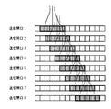
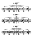
- the transmission aperture when the transmission aperture is composed of five ultrasonic elements, the transmission aperture is shifted by one element as shown by transmission apertures 1 to 8 in FIG.
- the ultrasonic beam is transmitted while shifting one line at a time.
- the number of transmission apertures constituted by five ultrasonic elements is an even number (eight in FIG. 7B), and transmission and reception of ultrasonic beams are performed as a pair of positive and negative transmission apertures whose phases are reversed.
- a pair of transmission apertures are determined in advance so as to constitute a pair of positive and negative transmission apertures whose phases are reversed at the transmission apertures where the sound pressure from the point of interest is the same, and an ultrasonic beam is transmitted.
- ultrasonic beams are transmitted and received corresponding to the scanning lines 1 to 8 while shifting the transmission aperture by one element.
- each opening at a symmetric position with respect to the scanning line is set as a positive phase opening and a negative phase opening, and the phases of adjacent transmission openings are alternately made positive and negative.
- superposition processing is performed using six of the element data corresponding to the scanning lines 1 to 8 obtained in this way, and element data corresponding to each scanning line after the superposition processing is generated.
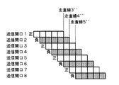
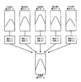
- element data corresponding to the scanning line 3 ′′, the scanning line 4 ′′, and the scanning line 5 ′′ is generated by superimposition processing as illustrated in FIG. 8B.
- the element data obtained by receiving at each opening is obtained by reversing the positive and negative phases in a pair of positive and negative openings where the sound pressure from the point of interest is the same. Since it becomes data, if it is added for each delay time ( ⁇ 0 to 2), only the second harmonic component is extracted. Therefore, the effect of side lobes is suppressed by performing the superimposition process using only the second harmonic component.
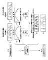
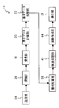
- FIG. 10 is a block diagram showing a main part of the ultrasonic diagnostic apparatus according to the present embodiment shown in FIG. 1 along the processing flow.
- the control unit 30 controls the transmission unit 14 based on the transmission phase for each transmission aperture stored in the storage unit 34 in advance, so that the pair of transmission apertures having the same sound pressure from the point of interest are in phase. Inverted positive and negative ultrasonic beams are transmitted.
- the probe 36 receives the ultrasonic echo generated by the interaction between the transmitted ultrasonic beam and the subject, and outputs an analog element signal as a reception signal.
- the receiving unit 16 amplifies the analog element signal and supplies it to the A / D conversion unit 18.
- the A / D conversion unit 18 converts the analog element signal into digital element data and converts the digital element data into an element data storage unit. 20 is stored and held.
- the element data processing unit 22 delays the unprocessed element data of the peripheral ghost signal with respect to the unprocessed element data of the true signal (for example, FIG. 6B, FIG. 6 (e), both of which are the same)), the geometrical arrangement of the transmitting element, the focal point, the reflection point, and the receiving element, and the speed of sound of the examination target region of the subject input and set in advance. (E.g., using the geometric model of FIGS. 5A and 5B).
- the element data processing unit 22 reads the unprocessed element data from the element data storage unit 20 and sets the element data to be processed as a target element.
- the delay time calculation unit 48 Using the calculated delay time, the element of interest and the surrounding unprocessed element data are phase-matched and overlapped to obtain processed element data.
- enhanced processed element data is obtained for unprocessed element data including a true signal
- attenuated processed element data is obtained for ghost unprocessed element data.
- the phase is inverted by performing superimposition processing in the superposition processing unit 50 by transmitting the ultrasonic beam by reversing the phases of the pair of transmission openings having the same sound pressure from the target point.
- the element data received through the pair of apertures is added to obtain processed element data from which only the second harmonic component is extracted.
- the element data processing unit 22 supplies the processed element data thus obtained to the phasing addition unit 38 of the image generation unit 24.
- the phasing addition unit 38 of the image generation unit 24 performs reception focus processing on the element data to generate reception data (sound ray signal) and supplies it to the detection processing unit 40.
- the detection processing unit 40 processes the sound ray signal and generates a B-mode image signal.
- the DSC 42 performs raster conversion on the B-mode image signal, and the image creation unit 44 performs image processing to generate an ultrasonic image.
- the generated ultrasonic image is stored in the image memory 46, and the ultrasonic image is displayed on the display unit 28 by the display control unit 26.
- the element data processing unit 22 uses the processed element data in which the ghost signal is attenuated and the true signal is emphasized. Therefore, an ultrasonic image with improved azimuth resolution and contrast resolution can be obtained.
- the transmission unit 14 controls the transmission unit 14 so as to transmit ultrasonic beams in which the phases of the pair of transmission apertures having the same sound pressure from the point of interest are inverted, the second harmonic is obtained. Since only the wave component is extracted and processed, the influence of side lobes can be suppressed.
- the number of frames is reduced by half because the image is generated by two transmissions, but the time resolution is reduced in this embodiment.
- the frame rate is not reduced and the same process as the normal overlay process is performed.
- the number of transmission openings is an even number
- the number of transmission openings may be an odd number.
- the sound pressure from the point of interest can be matched by setting each transmission aperture that is symmetric with respect to the scanning line to be a positive phase aperture and a negative phase aperture.
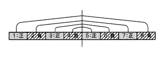
- the number of transmission apertures is an odd number, the sound pressure from the point of interest is different. Therefore, in this case, as shown in FIG.
- the coefficients ( ⁇ 0 to ⁇ 2) are determined in advance to match the sound pressure from the point of interest based on the profile of the ultrasonic beam, and the determined coefficients By performing the superimposition process using, it is possible to extract only the second harmonic component and suppress the influence of the side lobe as in the above embodiment.
- the unprocessed element data is subjected to superposition processing to generate processed element data, and then the phasing addition (reception focus) is performed on the processed element data.
- the reception data (sound ray signal) is generated.
- phasing addition (reception focus) is performed on the unprocessed element data to generate unprocessed reception data (sound ray signal), and then overlay processing is performed on the unprocessed reception data (sound ray signal)
- processed reception data sound ray signal
- the ultrasonic diagnostic apparatus 10 when calculating the delay time in the delay time calculation unit 48 of the element data processing unit 22 and when calculating the delay time used in the phasing addition unit 38.
- the necessary sound speed of the examination target region of the subject is given.
- the present invention is not limited to this, and when the sound speed in the inspection object is not known, an optimum sound speed may be obtained and set using various known methods.
- processing performed by each unit in the above embodiment may be stored and distributed as various programs in various storage media.
- the configuration, operation, and the like of the ultrasonic diagnostic apparatus 10 described in the present embodiment are examples, and it goes without saying that they can be changed according to the situation without departing from the gist of the present invention.
Landscapes
- Engineering & Computer Science (AREA)
- Physics & Mathematics (AREA)
- Remote Sensing (AREA)
- Radar, Positioning & Navigation (AREA)
- Health & Medical Sciences (AREA)
- Life Sciences & Earth Sciences (AREA)
- Acoustics & Sound (AREA)
- General Physics & Mathematics (AREA)
- Computer Networks & Wireless Communication (AREA)
- Pathology (AREA)
- Biomedical Technology (AREA)
- Medical Informatics (AREA)
- Molecular Biology (AREA)
- Surgery (AREA)
- Animal Behavior & Ethology (AREA)
- General Health & Medical Sciences (AREA)
- Public Health (AREA)
- Veterinary Medicine (AREA)
- Heart & Thoracic Surgery (AREA)
- Biophysics (AREA)
- Radiology & Medical Imaging (AREA)
- Nuclear Medicine, Radiotherapy & Molecular Imaging (AREA)
- Multimedia (AREA)
- Gynecology & Obstetrics (AREA)
- Nonlinear Science (AREA)
- Ultra Sonic Daignosis Equipment (AREA)
Priority Applications (1)
| Application Number | Priority Date | Filing Date | Title |
|---|---|---|---|
| US14/952,926 US20160139252A1 (en) | 2013-05-31 | 2015-11-26 | Ultrasound diagnostic device, method for generating acoustic ray signal of ultrasound diagnostic device, and program for generating acoustic ray signal of ultrasound diagnostic device |
Applications Claiming Priority (2)
| Application Number | Priority Date | Filing Date | Title |
|---|---|---|---|
| JP2013-116021 | 2013-05-31 | ||
| JP2013116021A JP2014233402A (ja) | 2013-05-31 | 2013-05-31 | 超音波診断装置、超音波診断装置の音線信号生成方法、及び超音波診断装置の音線信号生成プログラム |
Related Child Applications (1)
| Application Number | Title | Priority Date | Filing Date |
|---|---|---|---|
| US14/952,926 Continuation US20160139252A1 (en) | 2013-05-31 | 2015-11-26 | Ultrasound diagnostic device, method for generating acoustic ray signal of ultrasound diagnostic device, and program for generating acoustic ray signal of ultrasound diagnostic device |
Publications (1)
| Publication Number | Publication Date |
|---|---|
| WO2014192466A1 true WO2014192466A1 (ja) | 2014-12-04 |
Family
ID=51988505
Family Applications (1)
| Application Number | Title | Priority Date | Filing Date |
|---|---|---|---|
| PCT/JP2014/061319 Ceased WO2014192466A1 (ja) | 2013-05-31 | 2014-04-22 | 超音波診断装置、超音波診断装置の音線信号生成方法、及び超音波診断装置の音線信号生成プログラム |
Country Status (3)
| Country | Link |
|---|---|
| US (1) | US20160139252A1 (enExample) |
| JP (1) | JP2014233402A (enExample) |
| WO (1) | WO2014192466A1 (enExample) |
Families Citing this family (4)
| Publication number | Priority date | Publication date | Assignee | Title |
|---|---|---|---|---|
| US11395641B2 (en) | 2018-12-21 | 2022-07-26 | Industrial Technology Research Institute | Ultrasonic imaging device and imaging method thereof |
| WO2021240756A1 (ja) * | 2020-05-28 | 2021-12-02 | オリンパス株式会社 | 超音波信号処理装置、超音波信号処理装置の作動方法、及び超音波信号処理装置の作動プログラム |
| JP7666180B2 (ja) * | 2021-07-06 | 2025-04-22 | 大同特殊鋼株式会社 | 超音波探傷方法 |
| CN117159023B (zh) * | 2023-08-14 | 2025-04-18 | 逸超医疗科技(北京)有限公司 | 一种基于组织谐波成像优化的方法及设备 |
Citations (3)
| Publication number | Priority date | Publication date | Assignee | Title |
|---|---|---|---|---|
| JP2005081150A (ja) * | 2003-09-09 | 2005-03-31 | Ge Medical Systems Global Technology Co Llc | 自然発生的(組織)復号型符号化励起による組織高調波撮像の方法及び装置 |
| US20090227872A1 (en) * | 2008-03-10 | 2009-09-10 | Lihong Pan | Method and apparatus for sub-harmonic contrast imaging |
| JP2010051375A (ja) * | 2008-08-26 | 2010-03-11 | Aloka Co Ltd | 超音波画像形成装置および超音波画像形成方法 |
Family Cites Families (1)
| Publication number | Priority date | Publication date | Assignee | Title |
|---|---|---|---|---|
| US6589177B1 (en) * | 2002-11-15 | 2003-07-08 | Koninklijke Philips Electronics N.V. | Method and apparatus for obtaining B-flow and B-mode data from multiline beams in an ultrasound imaging system |
-
2013
- 2013-05-31 JP JP2013116021A patent/JP2014233402A/ja active Pending
-
2014
- 2014-04-22 WO PCT/JP2014/061319 patent/WO2014192466A1/ja not_active Ceased
-
2015
- 2015-11-26 US US14/952,926 patent/US20160139252A1/en not_active Abandoned
Patent Citations (3)
| Publication number | Priority date | Publication date | Assignee | Title |
|---|---|---|---|---|
| JP2005081150A (ja) * | 2003-09-09 | 2005-03-31 | Ge Medical Systems Global Technology Co Llc | 自然発生的(組織)復号型符号化励起による組織高調波撮像の方法及び装置 |
| US20090227872A1 (en) * | 2008-03-10 | 2009-09-10 | Lihong Pan | Method and apparatus for sub-harmonic contrast imaging |
| JP2010051375A (ja) * | 2008-08-26 | 2010-03-11 | Aloka Co Ltd | 超音波画像形成装置および超音波画像形成方法 |
Also Published As
| Publication number | Publication date |
|---|---|
| JP2014233402A (ja) | 2014-12-15 |
| US20160139252A1 (en) | 2016-05-19 |
Similar Documents
| Publication | Publication Date | Title |
|---|---|---|
| JP5905856B2 (ja) | 超音波検査装置 | |
| JP5946427B2 (ja) | 超音波検査装置、超音波検査方法、プログラム及び記録媒体 | |
| US11439368B2 (en) | Acoustic wave processing device, signal processing method for acoustic wave processing device, and program | |
| JP5905808B2 (ja) | 超音波検査装置、超音波画像データ生成方法およびプログラム | |
| JP6000196B2 (ja) | 超音波診断装置、音速決定方法およびプログラム | |
| WO2014050752A1 (ja) | 超音波診断装置、超音波画像生成方法およびプログラム | |
| US10231709B2 (en) | Ultrasound diagnostic apparatus, signal processing method for ultrasound diagnostic apparatus, and recording medium | |
| JP6110760B2 (ja) | 超音波診断装置および超音波診断装置の作動方法 | |
| WO2015145836A1 (ja) | 音響波処理装置、音響波処理装置の信号処理方法およびプログラム | |
| WO2014192466A1 (ja) | 超音波診断装置、超音波診断装置の音線信号生成方法、及び超音波診断装置の音線信号生成プログラム | |
| JP5964774B2 (ja) | 超音波診断装置、超音波診断装置の信号処理方法およびプログラム | |
| JP5873412B2 (ja) | 超音波診断装置、音速決定方法およびプログラム | |
| US10383601B2 (en) | Acoustic wave processing apparatus, signal processing method, and program for acoustic wave processing apparatus | |
| JP6047041B2 (ja) | 超音波診断装置、超音波診断装置の信号処理方法およびプログラム | |
| WO2014050847A1 (ja) | 超音波診断装置、超音波画像データ生成方法およびプログラム | |
| WO2014050756A1 (ja) | 超音波検査装置、超音波画像データ生成方法およびプログラム | |
| WO2014050897A1 (ja) | 超音波検査装置、超音波画像データ生成方法およびプログラム |
Legal Events
| Date | Code | Title | Description |
|---|---|---|---|
| 121 | Ep: the epo has been informed by wipo that ep was designated in this application |
Ref document number: 14804972 Country of ref document: EP Kind code of ref document: A1 |
|
| NENP | Non-entry into the national phase |
Ref country code: DE |
|
| 122 | Ep: pct application non-entry in european phase |
Ref document number: 14804972 Country of ref document: EP Kind code of ref document: A1 |