WO2014192308A1 - 車両用報知装置 - Google Patents
車両用報知装置 Download PDFInfo
- Publication number
- WO2014192308A1 WO2014192308A1 PCT/JP2014/002865 JP2014002865W WO2014192308A1 WO 2014192308 A1 WO2014192308 A1 WO 2014192308A1 JP 2014002865 W JP2014002865 W JP 2014002865W WO 2014192308 A1 WO2014192308 A1 WO 2014192308A1
- Authority
- WO
- WIPO (PCT)
- Prior art keywords
- vehicle
- notification
- processing unit
- obstacle
- driver
- Prior art date
- Legal status (The legal status is an assumption and is not a legal conclusion. Google has not performed a legal analysis and makes no representation as to the accuracy of the status listed.)
- Ceased
Links
Images


Classifications
-
- G—PHYSICS
- G08—SIGNALLING
- G08G—TRAFFIC CONTROL SYSTEMS
- G08G1/00—Traffic control systems for road vehicles
- G08G1/16—Anti-collision systems
- G08G1/166—Anti-collision systems for active traffic, e.g. moving vehicles, pedestrians, bikes
-
- G—PHYSICS
- G08—SIGNALLING
- G08G—TRAFFIC CONTROL SYSTEMS
- G08G1/00—Traffic control systems for road vehicles
- G08G1/16—Anti-collision systems
- G08G1/167—Driving aids for lane monitoring, lane changing, e.g. blind spot detection
Definitions
- the present disclosure relates to a vehicle notification device that notifies a vehicle driver.
- This disclosure is intended to provide a vehicle notification device that performs notification to a vehicle driver that suppresses safety confirmation from being performed in a situation where safety confirmation is highly necessary.
- the vehicle notification device includes a confirmation determination unit that determines whether or not a safety check to be performed for a predetermined driving operation is performed by the driver, and the predetermined driving operation is started.
- Start detecting means for detecting that the vehicle has been operated, informing means for notifying the driver when it is determined that the predetermined driving operation has been started in a situation where the safety check has not been performed, and the predetermined driving Fault judging means for judging whether or not there is an object that can hinder the movement of the vehicle accompanying the operation.
- the notification means performs the notification in a first notification mode when it is determined that the object is present. When it is determined that the object does not exist, the notification unit performs the notification in a second notification mode different from the first notification mode.
- the safety confirmation by the driver is not performed. This can be suppressed.
- FIG. 1 is a block diagram showing the configuration of the in-vehicle system.
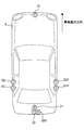
- FIG. 2 is a diagram showing the installation positions of the camera, the obstacle sensor, and the microphone outside the vehicle compartment
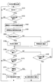
- FIG. 3 is a flowchart of the direction instruction warning process.
- FIG. 4 is a flowchart of the reverse warning process.
- the in-vehicle system shown in FIG. 1 is mounted on a vehicle and mainly configured with a safety confirmation warning device 1.
- the safety confirmation warning device 1 includes a signal processing unit 111, a sound input unit 112, a GPS receiver 113, a gyroscope 114, and a video input unit 115.
- the safety confirmation warning device 1 further includes a communication control unit 121, a map database 122, a memory 123, a filter / mute circuit 131, a video output conversion unit 132, and an arithmetic processing unit 14.
- the signal processing unit 111 inputs a vehicle signal (detection information by the sensors) from sensors (not shown) mounted on the vehicle and outputs them to the arithmetic processing unit 14.
- the signal processing unit 111 inputs detection information (information indicating the traveling speed) by a vehicle speed sensor (not shown) that detects the traveling speed of the vehicle.
- the signal processing unit 111 also detects detection information (information indicating at least whether or not the shift lever position is reverse (reverse running)) by a shift position sensor (not shown) that detects the position of the shift lever operated by the driver. input.
- the sound input unit 112 inputs an input sound from the microphone 21 outside the vehicle that inputs a sound outside the vehicle, and outputs it to the arithmetic processing unit 14.
- the outside-vehicle microphone 21 is arranged at the rear part of the vehicle 8 and mainly inputs sound behind the vehicle 8.
- the GPS receiver 113 receives a transmission signal from an artificial satellite for GPS (Global Positioning System) and detects the position coordinates of the vehicle.
- GPS Global Positioning System
- the gyroscope 114 outputs a detection signal corresponding to the angular velocity of the rotational motion applied to the vehicle.
- the video input unit 115 inputs video information from a plurality of cameras that photograph the outside (around) of the vehicle, and outputs the video information selected based on the switching signal from the arithmetic processing unit 14 to the arithmetic processing unit 14.
- the vehicle 8 of the present embodiment includes a front camera 51 that captures the front of the vehicle 8, side cameras 52 ⁇ / b> L and 52 ⁇ / b> R that capture the left and right sides of the vehicle 8, and a rear of the vehicle 8.
- a rear camera 53 for photographing is installed.
- Video information representing a video (image) taken by the front camera 51 is input by the front camera ECU 31.
- video information representing video shot by the side cameras 52L and 52R is input by the side camera ECU 32.
- video information representing video shot by the rear camera 53 installed at the rear of the vehicle is input by the rear camera ECU 33.
- the video input unit 115 inputs video information from each of the front camera ECU 31, the side camera ECU 32, and the rear camera ECU 33, and 1 of the input video information (video information from the plurality of cameras 51, 52L, 52R, 53). Are output to the arithmetic processing unit 14.
- the communication control unit 121 performs communication control via the communication bus 9 in the vehicle. Specifically, the information output from the arithmetic processing unit 14 is transmitted to another device connected to the communication bus 9 in the vehicle, and the information received from the other device via the communication bus 9 is calculated as the arithmetic processing unit. 14 to output.
- a vehicle interior camera ECU 34, a body ECU 35, a sonar ECU 36, a power steering ECU 37, and a display 41 are provided. included.
- the vehicle interior camera ECU 34 inputs video information representing the captured video from a vehicle interior camera (not shown) that is installed in the vehicle interior and captures the face of the driver, and the input video information is safely transmitted via the communication bus 9. It transmits to the confirmation warning device 1.
- the body ECU 35 inputs the operation state (left turn signal, right turn signal, off, etc.) of the direction indicator, and transmits the input information to the safety confirmation warning device 1 via the communication bus 9.
- the sonar ECU 36 inputs detection information from a plurality of obstacle sensors that detect obstacles outside (around) the vehicle, and transmits the input information to the safety confirmation warning device 1 via the communication bus 9.
- the vehicle 8 includes obstacle sensors 61L and 61R that detect obstacles on the left and right sides of the vehicle 8, and an obstacle sensor 61B that detects obstacles behind the vehicle 8. And are installed.
- Each obstacle sensor 61L, 61R, 61B detects the presence of an obstacle by transmitting an ultrasonic wave as a detection wave and receiving the reflected wave.
- the power steering ECU 37 inputs the steering state (steering angle) of the steering of the vehicle, and transmits the input information to the safety confirmation warning device 1 via the communication bus 9.
- the display device 41 is a device for displaying information visible to the driver, and includes, for example, a liquid crystal display and a lamp.
- the sound output device 42 is a device for outputting sound into the vehicle interior, and includes an amplifier, a speaker, and the like. Examples of output sounds include warning sounds and voice messages.
- the map database 122 is a storage device in which map data representing a map is stored.
- the memory 123 is a storage medium in which a program executed by the arithmetic processing unit 14 is stored.
- the filter / mute circuit 131 receives sound information from the arithmetic processing unit 14, converts the sound information into a form suitable for output (reproduced from a speaker) by the sound output unit 42, and outputs it to the sound output unit 42.
- the video output conversion unit 132 receives the video information from the arithmetic processing unit 14, converts it into a form suitable for display on the display 41, and outputs it to the display 41.
- the arithmetic processing unit 14 is configured using a microcomputer including a CPU, a ROM, a RAM, and the like, and executes various processes according to a program stored in the memory 123. For example, the arithmetic processing unit 14 calculates the current position (absolute position represented by latitude and longitude) and the traveling direction (absolute direction) of the vehicle based on detection information from the GPS receiver 113 and the gyroscope 114. The arithmetic processing unit 14 reads map data from the map database 122 and specifies the current position and traveling direction of the vehicle in the map represented by the map data.
- the arithmetic processing unit 14 determines whether or not the vehicle is traveling (S101). Specifically, when the traveling speed of the vehicle acquired via the signal processing section 111 is equal to or higher than a threshold value set as a criterion for determining that the vehicle is traveling, It is determined that the vehicle is traveling.
- the arithmetic processing unit 14 waits until the vehicle is traveling. On the other hand, if it is determined that the vehicle is traveling (S101: YES), the arithmetic processing unit 14 determines whether or not the direction indicator of the vehicle has been operated by the driver (S102). Specifically, the arithmetic processing unit 14 determines that the direction indicator is operated when the operation state of the direction indicator acquired from the body ECU 35 via the communication control unit 121 is the left turn signal or the right turn signal. To do.
- the arithmetic processing unit 14 determines that the direction indicator is not operated (S102: NO), it returns the process to S101.
- the arithmetic processing unit 14 monitors the safety confirmation by the driver (S103). Specifically, the arithmetic processing unit 14 analyzes video information acquired from the vehicle interior camera ECU 34 via the communication control unit 121 to detect the driver's face direction and line of sight. Then, based on the detected face orientation and line of sight, the arithmetic processing unit 14 monitors whether safety confirmation by visual inspection of the side mirror, the room mirror, the vehicle periphery, and the like has been performed. Note that the safety confirmation monitoring is continued until the processing returns to S101.
- the arithmetic processing unit 14 monitors obstacles around the vehicle (S104). Obstacles to be monitored are objects that can obstruct the movement of the vehicle, and specifically, other vehicles (automobiles, motorcycles, bicycles, etc.) and moving objects such as pedestrians are targeted. However, fixed objects such as signs installed on the road may also be included in the monitoring target. Obstacle monitoring is continued until the processing returns to S101.
- the arithmetic processing unit 14 analyzes video information acquired from the front camera ECU 31, the side camera ECU 32, and the rear camera ECU 33 via the communication control unit 121, and monitors obstacles around the vehicle. In addition, the arithmetic processing unit 14 acquires detection information from the sonar ECU 36 via the communication control unit 121 and monitors obstacles around the vehicle. Further, the arithmetic processing unit 14 analyzes the sound acquired from the vehicle interior microphone 21 via the sound input unit 112 and monitors an obstacle around the vehicle (for example, detects sound of an automobile, a motorcycle, or the like). ).
- the arithmetic processing unit 14 determines whether or not the right / left turn road corresponding to the operation state of the direction indicator exists within a predetermined distance range in front of the vehicle (traveling direction) (S105). Specifically, the arithmetic processing unit 14 determines whether or not there is a road that can turn left when the operation state of the turn indicator is the left turn signal, and there is a road that can turn right when the turn signal is the right turn signal. It is determined whether or not to do. Note that whether or not the right / left turn road is within a predetermined distance range in front of the vehicle is determined based on the current position and traveling direction of the vehicle in the map represented by the map data.
- the reason why the presence / absence of a right / left turn road is determined in this way is to distinguish whether the driver's operation of the direction indicator is for a right / left turn or a lane change. That is, when there is a road that can turn left or right near the direction of travel of the vehicle, if the direction indicator corresponding to the direction that can turn right or left is operated, the driver intends to turn right or left. There is a high possibility. On the contrary, when the direction indicator that does not correspond to the direction in which the vehicle can turn right or left is operated, there is a high possibility that the driver intends to change the lane. Therefore, based on the road near the traveling direction of the vehicle, it can be estimated whether the driver's intention is a right / left turn or a lane change.
- the arithmetic processing unit 14 determines that the right / left turn road corresponding to the operation state of the direction indicator exists within a predetermined distance range in front of the vehicle (S105: YES), the operation of the direction indicator makes a right / left turn. It is presumed that this is the intended one (S106). Specifically, the arithmetic processing unit 14 performs processing such as setting a flag indicating that the operation of the direction indicator is intended to turn left or right. Thereafter, the arithmetic processing unit 14 shifts the process to S108.
- the arithmetic processing unit 14 determines that the right / left turn road corresponding to the operation state of the direction indicator does not exist within the predetermined distance range in front of the vehicle (S105: NO), the operation of the direction indicator is performed. It is estimated that the lane change is intended (S107). Specifically, the arithmetic processing unit 14 performs processing such as setting a flag indicating that the operation of the direction indicator is intended to change lanes. Thereafter, the arithmetic processing unit 14 shifts the process to S108.
- the arithmetic processing unit 14 determines whether or not an operation to start turning off the steering of the vehicle is started by the driver. Specifically, when the steering angle of the steering acquired from the power steering ECU 37 via the communication control unit 121 is operated by a predetermined angle or more in a direction corresponding to the operation state of the direction indicator, It is determined that an operation to start turning off the steering is started.
- the driver performs a release operation of the direction indicator (an operation to release the left turn signal or right turn signal) by the driver. It is determined whether it has been received (S109). If it is determined that the direction indicator release operation has not been performed (S109: NO), the arithmetic processing unit 14 returns the process to S108. That is, as long as the state of the left turn signal or right turn signal continues in the operation state of the direction indicator, the operation waits until an operation for starting turning off is performed. On the other hand, when it is determined that the direction indicator has been released (S109: YES), the arithmetic processing unit 14 returns the process to S101.
- the arithmetic processing unit 14 determines the safety by the driver based on the monitoring result of the safety confirmation started in S103. It is determined whether confirmation has been performed (S110). Specifically, when it is estimated in S106 that the operation of the direction indicator is intended for a right or left turn, the arithmetic processing unit 14 turns right or left (left or right turn) corresponding to the operation state of the direction indicator. It is determined whether a safety check to be performed for the purpose has been performed.
- the arithmetic processing unit 14 changes the lane corresponding to the operation state of the direction indicator (to the left lane or the right lane). It is determined whether a safety check to be performed for lane change) has been performed.
- the arithmetic processing unit 14 determines that the safety confirmation by the driver has been performed (S110: YES), it returns the process to S101.
- the arithmetic processing unit 14 determines that the safety confirmation has not been performed (S110: NO)
- an obstacle that may become an obstacle to the movement of the vehicle is determined based on the obstacle monitoring result started in S104. It is determined whether or not it exists (S111).
- the arithmetic processing unit 14 detects an obstacle based on at least one of the cameras 51, 52L, 52R, and 53, the obstacle sensors 61L, 61R, and 61B, and the outside microphone 21. It is determined that an obstacle exists.
- the arithmetic processing unit 14 changes the right or left turn corresponding to the operation state of the direction indicator to a right or left turn. It is determined whether or not there is an obstacle that can be an obstacle to the movement of the accompanying vehicle. For example, in the case of a left turn, if there is an obstacle in at least one of the moving direction of the vehicle accompanying the left turn and the rear left side of the vehicle (the direction in which an obstacle approaching the moving direction of the vehicle can exist), the left turn It is determined that there is an obstacle that can be an obstacle to the movement of the vehicle due to.
- the arithmetic processing unit 14 determines the lane change corresponding to the operation state of the direction indicator for the vehicle accompanying the lane change. It is determined whether there is an obstacle that can be an obstacle to movement. For example, in the case of a lane change to the left lane, if there is an obstacle in at least one of the moving direction of the vehicle (left side of the vehicle) and the left rear of the vehicle, the lane change to the left lane It is determined that there is an obstacle that can be an obstacle to the movement of the vehicle due to.
- the arithmetic processing unit 14 determines that there is an obstacle that may be an obstacle to the movement of the vehicle when there is an obstacle in the direction that the driver should confirm (view) safety. In addition, it may be determined whether or not it can be an obstacle to the movement of the vehicle in consideration of the movement state of the obstacle (a temporal change in the relative position with respect to the vehicle).
- the arithmetic processing unit 14 determines that there is no obstacle that may be an obstacle to the movement of the vehicle (S111: NO)
- the arithmetic processing unit 14 performs notification in the first notification mode (S112), and then returns the processing to S101.
- the arithmetic processing unit 14 performs notification in the second notification mode (S113), and then proceeds to S101. return.
- the notification in the first notification mode is a notification mainly intended to notify the driver of forgetting to confirm the safety, and is performed by, for example, a warning sound and a warning display.
- the notification in the second notification mode is a notification mainly for notifying the driver of forgetting to confirm the safety, but also informing the danger, as compared with the first notification mode. Performed in a sensory manner.
- the volume of the warning sound (notification sound) is set larger than that in the first notification mode.
- the second notification mode includes, for example, different types of notification sounds (for example, fast tempo), a large amount of notification display (warning display), a different display color of notification display (for example, red), and the like. Any mode can be used as long as it can intuitively grasp that the degree of danger is higher than that of the first notification mode. Moreover, you may distinguish with the content of a voice message.
- the reverse warning process executed by the arithmetic processing unit 14 will be described with reference to the flowchart of FIG. Note that the reverse warning process of FIG. 4 is repeatedly executed as a process independent of the direction instruction warning process (FIG. 3) in a state where the engine of the vehicle is operating.
- the arithmetic processing unit 14 determines whether or not the shift lever has been operated in reverse (S201). Specifically, the arithmetic processing unit 14 determines that the shift lever has been operated in reverse when the detection information by the shift position sensor acquired via the signal processing unit 111 represents reverse.
- the arithmetic processing unit 14 waits until the shift lever is operated in reverse. On the other hand, when it is determined that the shift lever is operated in reverse (S201: YES), the arithmetic processing unit 14 monitors the safety confirmation by the driver (S202).
- the safety confirmation monitoring method is the same as that in S103 described above, and the safety confirmation monitoring is continued until the processing returns to S201.
- the safety confirmation monitoring may be performed specifically for safety confirmation to be performed for backward traveling (so that operations unnecessary for backward traveling are not monitored).
- the arithmetic processing unit 14 monitors obstacles around the vehicle (S203).
- the obstacle monitoring method is the same as S104 described above, and the obstacle monitoring is continued until the process returns to S201. Obstacles may be monitored specifically for the obstacles to be monitored in backward travel (so that obstacles such as front and side of the vehicle are not monitored).
- the arithmetic processing unit 14 determines whether or not the vehicle is stopped (a state in which the backward running is not started) (S204). Specifically, the arithmetic processing unit 14 has a vehicle running speed acquired via the signal processing unit 111 equal to or higher than a threshold set as a criterion for determining that the vehicle is stopped. It is determined that the vehicle is not stopped. Note that it may be determined that the vehicle is not stopped when an operation for releasing the brake is performed based on the state of the brake pedal.
- the arithmetic processing unit 14 determines whether or not the shift lever is operated other than reverse (reverse is released) (S205). If the arithmetic processing unit 14 determines that the reverse has not been canceled (S205: NO), it returns the process to S204. That is, as long as the shift lever is reverse, the vehicle waits until the vehicle travels. On the other hand, if the arithmetic processing unit 14 determines that the reverse has been canceled (S205: YES), it returns the process to S201.
- the arithmetic processing unit 14 returns the process to S201 when it is determined that the safety confirmation to be performed for the backward running is performed by the driver (S206: YES).
- the arithmetic processing unit 14 determines that the safety check has not been performed (S206: NO)
- the calculation processing unit 14 becomes an obstacle to the movement of the vehicle accompanying the backward traveling. It is determined whether there is an obstacle to obtain (S207).
- the method for determining whether or not an obstacle is present is the same as S111 described above. In the case of backward traveling, if it is determined that there is an obstacle behind the vehicle, it becomes an obstacle to movement of the vehicle due to backward traveling. Determine that there are obstacles to gain.
- the arithmetic processing unit 14 determines that there is no obstacle that may be an obstacle to the movement of the vehicle (S207: NO), the arithmetic processing unit 14 performs notification in the first notification mode (S208), and then returns the processing to S201. .
- the arithmetic processing unit 14 performs notification in the second notification mode (S209), and then proceeds to S101. return.
- the notification method according to the first notification mode and the second notification mode is the same as S112 and S113 described above.
- the safety confirmation warning device 1 detects that a predetermined driving operation (a driving operation for turning left or right, changing lanes or driving backward) is started (S108, S204). Further, the safety confirmation warning device 1 determines whether or not a safety confirmation to be performed for a predetermined driving operation has been performed by the driver (S110, S206). When the safety confirmation warning device 1 determines that a predetermined driving operation is started in a situation where safety confirmation is not performed (S110: NO, S206: NO), the safety confirmation warning device 1 notifies the driver (S112, S113). , S208, S209).
- a predetermined driving operation a driving operation for turning left or right, changing lanes or driving backward
- the safety confirmation warning device 1 determines whether or not there is an object (obstacle) that can be an obstacle to the movement of the vehicle accompanying a predetermined driving operation (S111, S207).
- the safety confirmation warning device 1 performs notification in the first notification mode when it is determined that an obstacle is present (S112, S208), and when it is determined that there is no obstacle, Notification is performed in a second notification mode different from the notification mode (S113, S209).
- the safety confirmation warning device 1 detects a pre-operation performed by the vehicle driver prior to a predetermined driving operation (S102, S201). Then, the safety confirmation warning device 1 starts monitoring the safety confirmation by the driver when a prior operation is detected (S103, S202), and whether the safety confirmation has been performed by the driver based on the monitoring result. It is determined whether or not (S110, S206). Therefore, according to the present embodiment, it is possible to efficiently determine whether or not safety confirmation has been performed, as compared with the case where safety confirmation is constantly monitored.
- the safety confirmation warning device 1 monitors the presence of an obstacle when a pre-operation is detected (S104, S203), and determines whether there is an obstacle based on the monitoring result. (S111, S207). Therefore, according to the present embodiment, it is possible to efficiently determine whether or not there is an obstacle as compared with the case where the obstacle is constantly monitored.
- the arithmetic processing unit 14 of the safety confirmation warning device 1 corresponds to an example of a vehicle notification device.
- S102 and S201 correspond to an example of processing as a prior detection unit
- S103 and S202 correspond to an example of processing as a confirmation monitoring unit
- S104 and S203 correspond to an example of processing as a failure monitoring unit.
- S108 and S204 correspond to an example of processing as a start detection unit
- S110 and S206 correspond to an example of processing as a confirmation determination unit
- S111 and S207 correspond to an example of processing as a failure determination unit.
- S112, S113, S208, and S209 correspond to an example of processing as notification means.
- the present invention is not limited to this. For example, the determination may be made based on the route guidance function (planned travel route) of the navigation system. If it determines in this way, it can determine more correctly whether it is a right-left turn or a lane change. Alternatively, information on the number of lanes on the road and information on the lane in which the vehicle is traveling may be acquired. . If such a determination is added, an erroneous determination can be made difficult to occur.
- route guidance function planned travel route
- the configuration and method for detecting the safety confirmation by the driver are not particularly limited. For example, if the video image captured by the rear camera 53 is displayed on the display unit 41 while traveling backward, it may be detected as a safety confirmation that the driver is viewing the display unit 41.
- the configuration and method for detecting an obstacle are not particularly limited. For example, it may be detected using only a camera, or may be detected using only an obstacle sensor. Moreover, you may detect using another apparatus (radar etc.).
- the configuration and method for notifying the driver are not particularly limited. For example, only visual notification may be performed, only auditory notification may be performed, or visual and auditory notification may be performed as in the above embodiment. Further, tactile notification (for example, notification by vibration) may be performed.
- the timing of notification is not limited to the example of the above embodiment.
- the notification is made when the backward running is started after the shift lever is operated in reverse. Instead, the notification is made immediately after the shift lever is operated in reverse. May be performed.
- the functions of one component in the above embodiment may be distributed as a plurality of components, or the functions of a plurality of components may be integrated into one component. Further, at least a part of the configuration of the above embodiment may be replaced with a known configuration having the same function. Moreover, you may abbreviate
- a program for causing a computer to function as the vehicle notification device in addition to the vehicle notification device, a recording medium storing the program, and a device (system) including the vehicle notification device as components. It can be realized in various forms such as a notification method.
- each section is expressed as S101, for example.
- each section can be divided into a plurality of subsections, while a plurality of sections can be combined into one section.
- each section configured in this manner can be referred to as a device, module, or means.
Landscapes
- Physics & Mathematics (AREA)
- General Physics & Mathematics (AREA)
- Traffic Control Systems (AREA)
Abstract
車両用報知装置は、所定の運転操作のための安全確認が運転者により行われたか否かを判定する確認判定手段(S110,S206)と、前記所定の運転操作が開始されたことを検出する開始検出手段(S108,S204)と、前記安全確認が行われておらず、前記所定の運転操作が開始された場合、運転者に対する報知を行う報知手段(S112,S113,S208,S209)と、障害判定手段(S111,S207)とを備える。前記報知手段は、障害物体が存在する場合には第1の報知態様で前記報知を行い、前記障害物体が存在しない場合には、第2の報知態様で前記報知を行う。
Description
本開示は、2013年5月31日に出願された日本出願番号2013-115751号に基づくもので、ここにその記載内容を援用する。
本開示は、車両の運転者に対する報知を行う車両用報知装置に関するものである。
車両を安全に走行させる上で、運転者による安全確認は重要であるが、例えば走り慣れた道路を運転する場合など、運転者が安全確認を怠りやすくなることがある。そこで、運転者が安全確認を怠った場合に、警告音を鳴らして運転者に対する報知を行う技術が提案されている(特許文献1参照)。
しかしながら、前述した技術では、安全確認を行う必要性が高い状況であるか否かに関係なく、安全確認を怠った場合に警告が行われるため、警告が行われるという状況に運転者が慣れてしまうことが考えられる。したがって、例えば車両の移動の障害となり得る物体(他車両や歩行者等)が存在する場合のように、安全確認を行う必要性が高い状況であるにもかかわらず、安全確認が行われない可能性がある。
本開示は、安全確認を行う必要性が高い状況において安全確認が行われないことを抑制する、車両の運転者に対する報知を行う車両用報知装置を提供することを目的とする。
本開示の第一の態様において、車両用報知装置は、所定の運転操作のために行うべき安全確認が運転者により行われたか否かを判定する確認判定手段と、前記所定の運転操作が開始されたことを検出する開始検出手段と、前記安全確認が行われていない状況において前記所定の運転操作が開始されたと判定された場合に、運転者に対する報知を行う報知手段と、前記所定の運転操作に伴う車両の移動の障害となり得る物体が存在するか否かを判定する障害判定手段とを備える。前記報知手段は、前記物体が存在すると判定された場合には第1の報知態様で前記報知を行う。前記報知手段は、前記物体が存在しないと判定された場合には、前記第1の報知態様とは異なる第2の報知態様で前記報知を行う。
上記の車両用報知装置によれば、所定の運転操作に伴う車両の移動の障害となり得る物体が存在する状況(安全確認を行う必要性が高い状況)において、運転者による安全確認が行われないことを抑制することが可能となる。
本開示についての上記目的およびその他の目的、特徴や利点は、添付の図面を参照しながら下記の詳細な記述により、より明確になる。その図面は、
図1は、車載システムの構成を示すブロック図であり、
図2は、カメラ、障害物センサ及び車室外マイクの設置位置を示す図であり、
図3は、方向指示警告処理のフローチャートであり、
図4は、リバース警告処理のフローチャートである。
以下、本開示が適用された実施形態について、図面を用いて説明する。
[1.構成]
図1に示す車載システムは、車両に搭載され、安全確認警告装置1を中心に構成されている。
図1に示す車載システムは、車両に搭載され、安全確認警告装置1を中心に構成されている。
安全確認警告装置1は、信号処理部111と、音入力部112と、GPS受信機113と、ジャイロスコープ114と、映像入力部115と、を備える。さらに、安全確認警告装置1は、通信制御部121と、地図データベース122と、メモリ123と、フィルタ/ミュート回路131と、映像出力変換部132と、演算処理部14と、を備える。
信号処理部111は、車両に搭載されたセンサ類(図示せず)から車両信号(センサ類による検出情報)を入力し、演算処理部14へ出力する。本実施形態では、信号処理部111は、車両の走行速度を検出する図示しない車速センサによる検出情報(走行速度を表す情報)を入力する。また、信号処理部111は、運転者が操作するシフトレバーのポジションを検出する図示しないシフトポジションセンサによる検出情報(シフトレバーのポジションがリバース(後方走行)であるか否かを少なくとも表す情報)を入力する。
音入力部112は、車両の外部の音を入力する車室外マイク21による入力音を入力し、演算処理部14へ出力する。車室外マイク21は、図2に示すように、車両8の後部に配置されており、主に車両8の後方における音を入力する。
GPS受信機113は、GPS(Global Positioning System)用の人工衛星からの送
信信号を受信し、車両の位置座標を検出する。
信信号を受信し、車両の位置座標を検出する。
ジャイロスコープ114は、車両に加えられる回転運動の角速度に応じた検出信号を出力する。
映像入力部115は、車両の外部(周囲)を撮影する複数のカメラからの映像情報を入力し、演算処理部14からの切替信号に基づき選択した映像情報を演算処理部14へ出力する。図2に示すように、本実施形態の車両8には、車両8の前方を撮影する前方カメラ51と、車両8の左右側方を撮影する側方カメラ52L,52Rと、車両8の後方を撮影する後方カメラ53と、が設置されている。前方カメラ51により撮影された映像(画像)を表す映像情報は、前方カメラECU31により入力される。また、側方カメラ52L,52Rにより撮影された映像を表す映像情報は、側方カメラECU32により入力される。また、車両の後方に設置された後方カメラ53により撮影された映像を表す映像情報は、後方カメラECU33により入力される。映像入力部115は、前方カメラECU31、側方カメラECU32及び後方カメラECU33のそれぞれから映像情報を入力し、入力した映像情報(複数のカメラ51,52L,52R,53による映像情報)のうちの1つを演算処理部14へ出力する。
通信制御部121は、車両内の通信バス9を介した通信制御を行う。具体的には、演算処理部14から出力された情報を、車両内の通信バス9に接続された他の装置へ送信し、通信バス9を介して他の装置から受信した情報を演算処理部14へ出力する。ここでいう他の装置としては、前述した前方カメラECU31、側方カメラECU32及び後方カメラECU33の他、車室内カメラECU34と、ボデーECU35と、ソナーECU36と、パワステECU37と、表示器41と、が含まれる。
車室内カメラECU34は、車両の室内に設置され運転者の顔を撮影する図示しない車室内カメラから、撮影された映像を表す映像情報を入力し、入力した映像情報を通信バス9を介して安全確認警告装置1へ送信する。
ボデーECU35は、方向指示器の操作状態(左ウインカ、右ウインカ、オフ等)を入力し、入力した情報を通信バス9を介して安全確認警告装置1へ送信する。
ソナーECU36は、車両の外部(周囲)の障害物を検出する複数の障害物センサからの検出情報を入力し、入力した情報を通信バス9を介して安全確認警告装置1へ送信する。図2に示すように、本実施形態の車両8には、車両8の左右側方の障害物を検出する障害物センサ61L,61Rと、車両8の後方の障害物を検出する障害物センサ61Bと、が設置されている。各障害物センサ61L,61R,61Bは、検出波としての超音波を発信し、その反射波を受信することにより障害物の存在を検出する。
パワステECU37は、車両のステアリングの操舵状態(操舵角)を入力し、入力した情報を通信バス9を介して安全確認警告装置1へ送信する。
表示器41は、運転者が視認可能な情報を表示するための装置であり、例えば液晶ディスプレイやランプなどが含まれる。
音出力器42は、車両の室内に音を出力するための装置であり、アンプやスピーカ等を備える。出力される音としては、例えば警告音や音声メッセージなどが含まれる。
地図データベース122は、地図を表す地図データが記憶された記憶装置である。
メモリ123は、演算処理部14により実行されるプログラム等が記憶される記憶媒体である。
フィルタ/ミュート回路131は、演算処理部14から音情報を入力し、音出力器42で出力(スピーカから再生)するのに適した形に変換して、音出力器42へ出力する。
映像出力変換部132は、演算処理部14から映像情報を入力し、表示器41で表示するのに適した形に変換して、表示器41へ出力する。
演算処理部14は、CPU、ROM、RAM等を備えたマイコンを用いて構成され、メモリ123に記憶されたプログラムに従い、各種処理を実行する。例えば、演算処理部14は、GPS受信機113及びジャイロスコープ114による検出情報に基づいて、車両の現在位置(緯度及び経度で表される絶対位置)及び走行方向(絶対方位)を算出する。また、演算処理部14は、地図データベース122から地図データを読み込み、地図データの表す地図における車両の現在位置及び走行方向を特定する。
[2.処理]
次に、演算処理部14が実行する方向指示警告処理について、図3のフローチャートを用いて説明する。なお、図3の方向指示警告処理は、車両のエンジンが作動している状態において繰り返し実行される。
次に、演算処理部14が実行する方向指示警告処理について、図3のフローチャートを用いて説明する。なお、図3の方向指示警告処理は、車両のエンジンが作動している状態において繰り返し実行される。
まず、演算処理部14は、車両が走行中であるか否かを判定する(S101)。具体的には、演算処理部14は、信号処理部111を介して取得される車両の走行速度が、車両が走行中であることの判定基準として設定されているしきい値以上の場合に、車両が走行中であると判定する。
演算処理部14は、車両が走行中でないと判定した場合には(S101:NO)、車両が走行中となるまで待機する。一方、演算処理部14は、車両が走行中であると判定した場合には(S101:YES)、車両の方向指示器が運転者により操作されたか否かを判定する(S102)。具体的には、演算処理部14は、通信制御部121を介してボデーECU35から取得される方向指示器の操作状態が、左ウインカ又は右ウインカである場合に、方向指示器が操作されたと判定する。
演算処理部14は、方向指示器が操作されていないと判定した場合には(S102:NO)、処理をS101に戻す。一方、演算処理部14は、方向指示器が操作されたと判定した場合には(S102:YES)、運転者による安全確認を監視する(S103)。具体的には、演算処理部14は、通信制御部121を介して車室内カメラECU34から取得される映像情報を解析し、運転者の顔向き及び視線を検出する。そして、演算処理部14は、検出した顔向き及び視線に基づいて、サイドミラー、ルームミラー、車両周辺等の目視による安全確認が行われたかを監視する。なお、安全確認の監視は、処理がS101に戻るまで継続される。
続いて、演算処理部14は、車両の周辺における障害物を監視する(S104)。監視対象の障害物は、車両の移動の障害となり得る物体であり、具体的には、他の車両(自動車、自動二輪車、自転車等)や歩行者などの移動体が対象となる。ただし、道路に設置された標識などの固定物についても監視対象に含めてもよい。なお、障害物の監視は、処理がS101に戻るまで継続される。
具体的には、演算処理部14は、通信制御部121を介して前方カメラECU31、側方カメラECU32及び後方カメラECU33から取得される映像情報を解析し、車両の周辺における障害物を監視する。また、演算処理部14は、通信制御部121を介してソナーECU36による検出情報を取得し、車両の周辺における障害物を監視する。さらに、演算処理部14は、音入力部112を介して車室外マイク21から取得される音を解析し、車両の周辺における障害物を監視する(例えば、自動車や自動二輪車等の音を検出する)。
続いて、演算処理部14は、方向指示器の操作状態に対応する右左折道路が、車両の前方(進行方向)における所定距離範囲内に存在するか否かを判定する(S105)。具体的には、演算処理部14は、方向指示器の操作状態が左ウインカの場合には左折可能な道路が存在するか否かを判定し、右ウインカの場合には右折可能な道路が存在するか否かを判定する。なお、右左折道路が車両の前方における所定距離範囲内に存在するか否かは、地図データの表す地図における車両の現在位置及び走行方向に基づいて判定される。
このように右左折道路の存在の有無を判定する理由は、運転者による方向指示器の操作が右左折のためのものであるか車線変更のためのものであるかを区別するためである。すなわち、車両の進行方向近くに左折又は右折が可能な道路が存在する状態で、右左折可能な方向に対応する方向指示器の操作が行われた場合には、運転者が右左折を意図している可能性が高い。逆に、右左折可能な方向に対応しない方向指示器の操作が行われた場合には、運転者が車線変更を意図している可能性が高い。したがって、車両の進行方向近くの道路に基づいて、運転者の意図が右左折であるか車線変更であるかを推測することができる。
演算処理部14は、方向指示器の操作状態に対応する右左折道路が車両の前方における所定距離範囲内に存在すると判定した場合には(S105:YES)、方向指示器の操作が右左折を意図したものであると推測する(S106)。具体的には、演算処理部14は、方向指示器の操作が右左折を意図したものであることを示すフラグを立てるなどの処理を行う。その後、演算処理部14は、処理をS108へ移行させる。
一方、演算処理部14は、方向指示器の操作状態に対応する右左折道路が車両の前方における所定距離範囲内に存在しないと判定した場合には(S105:NO)、方向指示器の操作が車線変更を意図したものであると推測する(S107)。具体的には、演算処理部14は、方向指示器の操作が車線変更を意図したものであることを示すフラグを立てるなどの処理を行う。その後、演算処理部14は、処理をS108へ移行させる。
S108で、演算処理部14は、運転者により車両のステアリングを切り始める操作が開始されたか否かを判定する。具体的には、演算処理部14は、通信制御部121を介してパワステECU37から取得されるステアリングの操舵角が、方向指示器の操作状態に対応する方向において所定角度以上操作された場合に、ステアリングを切り始める操作が開始されたと判定する。
演算処理部14は、ステアリングを切り始める操作が開始されていないと判定した場合には(S108:NO)、方向指示器の解除操作(左ウインカ又は右ウインカを解除する操作)が運転者により行われたか否かを判定する(S109)。演算処理部14は、方向指示器の解除操作が行われていないと判定した場合には(S109:NO)、処理をS108に戻す。つまり、方向指示器の操作状態で左ウインカ又は右ウインカの状態が継続している限り、ステアリングを切り始める操作が行われるまで待機する。一方、演算処理部14は、方向指示器の解除操作が行われたと判定した場合には(S109:YES)、処理をS101に戻す。
また、演算処理部14は、前述したS108で、ステアリングを切り始める操作が開始されたと判定した場合には(S108:YES)、S103で開始した安全確認の監視結果に基づいて、運転者による安全確認が行われたか否かを判定する(S110)。具体的には、演算処理部14は、S106で方向指示器の操作が右左折を意図したものであると推測した場合には、方向指示器の操作状態に対応する右左折(左折又は右折)のために行うべき安全確認が行われたか否かを判定する。一方、演算処理部14は、S107で方向指示器の操作が車線変更を意図したものであると推測した場合には、方向指示器の操作状態に対応する車線変更(左車線又は右車線への車線変更)のために行うべき安全確認が行われたか否かを判定する。
演算処理部14は、運転者による安全確認が行われたと判定した場合には(S110:YES)、処理をS101に戻す。一方、演算処理部14は、安全確認が行われていないと判定した場合には(S110:NO)、S104で開始した障害物の監視結果に基づいて、車両の移動の障害となり得る障害物が存在するか否かを判定する(S111)。本実施形態では、演算処理部14は、カメラ51,52L,52R,53、障害物センサ61L,61R,61B及び車室外マイク21のうち少なくとも1つに基づいて障害物が検出された場合に、障害物が存在すると判定する。
具体的には、演算処理部14は、S106で方向指示器の操作が右左折を意図したものであると推測した場合には、方向指示器の操作状態に対応する右左折について、右左折に伴う車両の移動の障害となり得る障害物が存在するか否かを判定する。例えば左折の場合、左折に伴う車両の移動方向と、車両の左側後方(車両の移動方向へ接近する障害物が存在し得る方向)と、のうち少なくとも一方に障害物が存在する場合に、左折に伴う車両の移動の障害となり得る障害物が存在すると判定する。また、例えば右折の場合、右折に伴う車両の移動方向と、車両の右側前方(車両の移動方向へ接近する障害物が存在し得る方向)と、のうち少なくとも一方に障害物が存在する場合に、右左折に伴う車両の移動の障害となり得る障害物が存在すると判定する。
一方、演算処理部14は、S107で方向指示器の操作が車線変更を意図したものであると推測した場合には、方向指示器の操作状態に対応する車線変更について、車線変更に伴う車両の移動の障害となり得る障害物が存在するか否かを判定する。例えば左車線への車線変更の場合、車線変更に伴う車両の移動方向(車両の左側)と、車両の左側後方と、のうち少なくとも一方に障害物が存在する場合に、左車線への車線変更に伴う車両の移動の障害となり得る障害物が存在すると判定する。また、例えば右車線への車線変更の場合、車線変更に伴う車両の移動方向(車両の右側)と、車両の右側後方と、のうち少なくとも一方に障害物が存在する場合に、右車線への車線変更に伴う車両の移動の障害となり得る障害物が存在すると判定する。
つまり、演算処理部14は、運転者が安全確認(目視)すべき方向に障害物が存在する場合に、車両の移動の障害となり得る障害物が存在すると判定する。なお、障害物の移動状態(車両に対する相対位置の時間的変化)を加味して、車両の移動の障害となり得るか否かを判定してもよい。
演算処理部14は、車両の移動の障害となり得る障害物が存在しないと判定した場合には(S111:NO)、第1の報知態様で報知を行った後(S112)、処理をS101に戻す。一方、演算処理部14は、車両の移動の障害となり得る障害物が存在すると判定した場合には(S111:YES)、第2の報知態様で報知を行った後(S113)、処理をS101に戻す。
第1の報知態様での報知は、運転者に安全確認のし忘れを知らせることを主目的とした報知であり、例えば警告音及び警告表示により行われる。これに対し、第2の報知態様での報知は、運転者に安全確認のし忘れを知らせることに加え、危険を知らせることを主目的とした報知であり、第1の報知態様と比較して感覚的に強い態様で行われる。本実施形態では、第2の報知態様は、第1の報知態様と比較して、警告音(報知音)の音量が大きく設定されている。なお、第2の報知態様は、例えば、報知音の種類が異なる(例えばテンポが速い)、報知表示(警告表示)の表示量が多い、報知表示の表示色が異なる(例えば赤色)など、第1の報知態様と比較して危険度合いが高いことを直感的に把握できる態様であればよい。また、音声メッセージの内容で区別してもよい。
次に、演算処理部14が実行するリバース警告処理について、図4のフローチャートを用いて説明する。なお、図4のリバース警告処理は、車両のエンジンが作動している状態において、方向指示警告処理(図3)とは独立した処理として繰り返し実行される。
まず、演算処理部14は、シフトレバーがリバースに操作されたか否かを判定する(S201)。具体的には、演算処理部14は、信号処理部111を介して取得されるシフトポジションセンサによる検出情報がリバースを表している場合に、シフトレバーがリバースに操作されたと判定する。
演算処理部14は、シフトレバーがリバースに操作されていないと判定した場合には(S201:NO)、シフトレバーがリバースに操作されるまで待機する。一方、演算処理部14は、シフトレバーがリバースに操作されたと判定した場合には(S201:YES)、運転者による安全確認を監視する(S202)。安全確認の監視の手法は、前述したS103と同様であり、安全確認の監視は、処理がS201に戻るまで継続される。なお、安全確認の監視は、後方走行のために行うべき安全確認に特化して行うように(後方走行に不要な動作等は監視対象としないように)してもよい。
続いて、演算処理部14は、車両の周辺における障害物を監視する(S203)。障害物の監視の手法は、前述したS104と同様であり、障害物の監視は、処理がS201に戻るまで継続される。なお、障害物の監視は、後方走行において監視すべき障害物に特化して行うように(車両の前方や側方などの障害物は監視対象としないように)してもよい。
続いて、演算処理部14は、車両が停止中(後方走行が開始されていない状態)であるか否かを判定する(S204)。具体的には、演算処理部14は、信号処理部111を介して取得される車両の走行速度が、車両が停止中であることの判定基準として設定されているしきい値以上の場合に、車両が停止中でないと判定する。なお、ブレーキペダルの状態に基づいて、ブレーキを解除する操作が行われた場合に停止中でないと判定してもよい。
演算処理部14は、車両が停止中であると判定した場合には(S204:YES)、シフトレバーがリバース以外に操作された(リバースが解除された)か否かを判定する(S205)。演算処理部14は、リバースが解除されていないと判定した場合には(S205:NO)、処理をS204に戻す。つまり、シフトレバーがリバースとなっている限り、車両が走行するまで待機する。一方、演算処理部14は、リバースが解除されたと判定した場合には(S205:YES)、処理をS201に戻す。
また、演算処理部14は、前述したS204で、車両が停止中でない(後方走行が開始された)と判定した場合には(S204:NO)、S202で開始した安全確認の監視結果に基づいて、後方走行のために行うべき安全確認が運転者により行われたか否かを判定する(S206)。
演算処理部14は、後方走行のために行うべき安全確認が運転者により行われたと判定した場合には(S206:YES)、処理をS201に戻す。一方、演算処理部14は、安全確認が行われていないと判定した場合には(S206:NO)、S203で開始した障害物の監視結果に基づいて、後方走行に伴う車両の移動の障害となり得る障害物が存在するか否かを判定する(S207)。障害物が存在するか否かの判定手法は、前述したS111と同様であり、後方走行の場合、車両の後方に障害物が存在すると判定した場合に、後方走行に伴う車両の移動の障害となり得る障害物が存在すると判定する。
演算処理部14は、車両の移動の障害となり得る障害物が存在しないと判定した場合には(S207:NO)、第1の報知態様で報知を行った後(S208)、処理をS201に戻す。一方、演算処理部14は、車両の移動の障害となり得る障害物が存在すると判定した場合には(S207:YES)、第2の報知態様で報知を行った後(S209)、処理をS101に戻す。第1の報知態様及び第2の報知態様による報知の手法は、前述したS112,S113と同様である。
[3.効果]
以上詳述した実施形態によれば、以下の効果が得られる。
以上詳述した実施形態によれば、以下の効果が得られる。
[3A]安全確認警告装置1は、所定の運転操作(右左折、車線変更又は後方走行のための運転操作)が開始されたことを検出する(S108,S204)。また、安全確認警告装置1は、所定の運転操作のために行うべき安全確認が運転者により行われたか否かを判定する(S110,S206)。そして、安全確認警告装置1は、安全確認が行われていない状況において所定の運転操作が開始されたと判定した場合に(S110:NO,S206:NO)、運転者に対する報知を行う(S112,S113,S208,S209)。具体的には、安全確認警告装置1は、所定の運転操作に伴う車両の移動の障害となり得る物体(障害物)が存在するか否かを判定する(S111,S207)。そして、安全確認警告装置1は、障害物が存在すると判定された場合には第1の報知態様で報知を行い(S112,S208)、障害物が存在しないと判定された場合には、第1の報知態様とは異なる第2の報知態様で報知を行う(S113,S209)。
したがって、本実施形態によれば、所定の運転操作に伴う車両の移動の障害となり得る障害物が存在する状況(安全確認を行う必要性が高い状況)において、運転者による安全確認が行われないことを抑制することが可能となる。
[3B]安全確認警告装置1は、車両の運転者が所定の運転操作に先立ち行う事前操作を検出する(S102,S201)。そして、安全確認警告装置1は、事前操作が検出された場合に、運転者による安全確認の監視を開始し(S103,S202)、当該監視結果に基づいて、安全確認が運転者により行われたか否かを判定する(S110,S206)。したがって、本実施形態によれば、安全確認の監視を常時行う場合と比較して、安全確認が行われたか否かを効率よく判定することができる。
[3C]安全確認警告装置1は、事前操作が検出された場合に、障害物の存在を監視し(S104,S203)、当該監視結果に基づいて、障害物が存在するか否かを判定する(S111,S207)。したがって、本実施形態によれば、障害物の監視を常時行う場合と比較して、障害物が存在するか否かを効率よく判定することができる。
[3D]第2の報知態様は、第1の報知態様と比較して、報知音の音量が大きいため、第1の報知態様と比較して危険度合いが高いことを運転者に直感的に把握させることができる。
なお、実施形態では、安全確認警告装置1の演算処理部14が車両用報知装置の一例に相当する。また、S102,S201が事前検出手段としての処理の一例に相当し、S103,S202が確認監視手段としての処理の一例に相当し、S104,S203が障害監視手段としての処理の一例に相当する。また、S108,S204が開始検出手段としての処理の一例に相当し、S110,S206が確認判定手段としての処理の一例に相当し、S111,S207が障害判定手段としての処理の一例に相当する。また、S112,S113,S208,S209が報知手段としての処理の一例に相当する。
[4.他の実施形態]
以上、本開示の実施形態について説明したが、本開示は、上記実施形態に限定されることなく、種々の形態を採り得ることは言うまでもない。
以上、本開示の実施形態について説明したが、本開示は、上記実施形態に限定されることなく、種々の形態を採り得ることは言うまでもない。
[4A]上記実施形態では、運転者による方向指示器の操作が右左折のためのものであるか車線変更のためのものであるかを、車両の前方における所定距離範囲内に右左折道路が存在するか否かに基づいて判定しているが、これに限定されるものではない。例えば、ナビゲーションシステムの経路案内機能(走行予定経路)に基づいて判定してもよい。このように判定すれば、右左折であるか車線変更であるかをより正確に判定することができる。また、道路の車線数や走行中の車線の情報を取得し、走行中の車線に対してウインカの方向に車線が存在しなければ、車線変更でない(右左折である)と判定してもよい。このような判定を加えれば、誤判定を生じにくくすることができる。
[4B]運転者による安全確認を検出するための構成や方法は特に限定されない。例えば、後方カメラ53により撮影された映像が後方走行中に表示器41に表示される構成であれば、運転者が表示器41を視認していることを安全確認として検出してもよい。
[4C]障害物を検出するための構成や方法は特に限定されない。例えば、カメラだけを用いて検出してもよく、障害物センサだけを用いて検出してもよい。また、他の装置(レーダ等)を用いて検出してもよい。
[4D]運転者に報知を行うための構成や方法は特に限定されない。例えば、視覚的な報知だけを行ってもよく、聴覚的な報知だけを行ってもよく、上記実施形態のように視覚的及び聴覚的な報知を行ってもよい。また、触覚的な報知(例えば振動による報知)を行ってもよい。
[4E]報知を行うタイミングは、上記実施形態の例に限定されない。例えば、上記実施形態では、シフトレバーがリバースに操作された後、後方走行が開始された時点で報知を行うようにしているが、これに代えて、シフトレバーがリバースに操作された直後に報知を行うようにしてもよい。
[4F]上記実施形態における1つの構成要素が有する機能を複数の構成要素として分散させたり、複数の構成要素が有する機能を1つの構成要素に統合したりしてもよい。また、上記実施形態の構成の少なくとも一部を、同様の機能を有する公知の構成に置き換えてもよい。また、上記実施形態の構成の一部を、課題を解決できる限りにおいて省略してもよい。また、上記実施形態の構成の少なくとも一部を、他の上記実施形態の構成に対して付加、置換等してもよい。
[4G]本開示は、車両用報知装置の他、当該車両用報知装置としてコンピュータを機能させるためのプログラム、このプログラムを記録した記録媒体、当該車両用報知装置を構成要素とする装置(システム)、報知方法など、種々の形態で実現することができる。
ここで、この出願に記載されるフローチャート、あるいは、フローチャートの処理は、複数のセクション(あるいはステップと言及される)から構成され、各セクションは、たとえば、S101と表現される。さらに、各セクションは、複数のサブセクションに分割されることができる、一方、複数のセクションが合わさって一つのセクションにすることも可能である。さらに、このように構成される各セクションは、デバイス、モジュール、ミーンズとして言及されることができる。
本開示は、実施例に準拠して記述されたが、本開示は当該実施例や構造に限定されるものではないと理解される。本開示は、様々な変形例や均等範囲内の変形をも包含する。加えて、様々な組み合わせや形態、さらには、それらに一要素のみ、それ以上、あるいはそれ以下、を含む他の組み合わせや形態をも、本開示の範疇や思想範囲に入るものである。
Claims (4)
- 所定の運転操作のために行うべき安全確認が運転者により行われたか否かを判定する確認判定手段(S110,S206)と、
前記所定の運転操作が開始されたことを検出する開始検出手段(S108,S204)と、
前記安全確認が行われていない状況において前記所定の運転操作が開始されたと判定された場合に、運転者に対する報知を行う報知手段(S112,S113,S208,S209)と、
前記所定の運転操作に伴う車両の移動の障害となり得る物体が存在するか否かを判定する障害判定手段(S111,S207)と、
を備え、
前記報知手段は、前記物体が存在すると判定された場合には第1の報知態様で前記報知を行い、
前記報知手段は、前記物体が存在しないと判定された場合には、前記第1の報知態様とは異なる第2の報知態様で前記報知を行う
車両用報知装置。 - 車両の運転者が所定の運転操作に先立ち行う事前操作を検出する事前検出手段(S102,S201)と、
前記事前操作が検出された場合に、運転者による前記安全確認の監視を開始する確認監視手段(S103,S202)と、
を更に備え、
前記確認判定手段は、前記確認監視手段による監視結果に基づいて、前記安全確認が運転者により行われたか否かを判定する
請求項1に記載の車両用報知装置。 - 前記事前操作が検出された場合に、前記物体の存在を監視する障害監視手段(S104,S203)を更に備え、
前記障害判定手段は、前記障害監視手段による監視結果に基づいて、前記物体が存在するか否かを判定する
請求項2に記載の車両用報知装置。 - 前記第2の報知態様は、前記第1の報知態様と比較して、報知音の音量が大きい
請求項1から請求項3までのいずれか1項に記載の車両用報知装置。
Applications Claiming Priority (2)
| Application Number | Priority Date | Filing Date | Title |
|---|---|---|---|
| JP2013-115751 | 2013-05-31 | ||
| JP2013115751A JP2014234037A (ja) | 2013-05-31 | 2013-05-31 | 車両用報知装置 |
Publications (1)
| Publication Number | Publication Date |
|---|---|
| WO2014192308A1 true WO2014192308A1 (ja) | 2014-12-04 |
Family
ID=51988359
Family Applications (1)
| Application Number | Title | Priority Date | Filing Date |
|---|---|---|---|
| PCT/JP2014/002865 Ceased WO2014192308A1 (ja) | 2013-05-31 | 2014-05-30 | 車両用報知装置 |
Country Status (2)
| Country | Link |
|---|---|
| JP (1) | JP2014234037A (ja) |
| WO (1) | WO2014192308A1 (ja) |
Families Citing this family (1)
| Publication number | Priority date | Publication date | Assignee | Title |
|---|---|---|---|---|
| WO2019167285A1 (ja) * | 2018-03-02 | 2019-09-06 | 三菱電機株式会社 | 運転支援装置及び運転支援方法 |
Citations (2)
| Publication number | Priority date | Publication date | Assignee | Title |
|---|---|---|---|---|
| JP2007133692A (ja) * | 2005-11-10 | 2007-05-31 | Toyota Motor Corp | 運転行動評価装置 |
| JP2008097278A (ja) * | 2006-10-11 | 2008-04-24 | Denso Corp | 運転支援装置 |
-
2013
- 2013-05-31 JP JP2013115751A patent/JP2014234037A/ja active Pending
-
2014
- 2014-05-30 WO PCT/JP2014/002865 patent/WO2014192308A1/ja not_active Ceased
Patent Citations (2)
| Publication number | Priority date | Publication date | Assignee | Title |
|---|---|---|---|---|
| JP2007133692A (ja) * | 2005-11-10 | 2007-05-31 | Toyota Motor Corp | 運転行動評価装置 |
| JP2008097278A (ja) * | 2006-10-11 | 2008-04-24 | Denso Corp | 運転支援装置 |
Also Published As
| Publication number | Publication date |
|---|---|
| JP2014234037A (ja) | 2014-12-15 |
Similar Documents
| Publication | Publication Date | Title |
|---|---|---|
| JP6031066B2 (ja) | 車両の走行制御装置 | |
| US20190071071A1 (en) | Vehicle control device, vehicle control method, and storage medium | |
| US20170021829A1 (en) | Vehicle control device | |
| US20190147267A1 (en) | Distracted driving determination apparatus, distracted driving determination method, and program for distracted driving determination | |
| JP6168025B2 (ja) | 車両用交差点関連警報装置 | |
| JP6654907B2 (ja) | 車両の走行制御装置 | |
| CN102667887A (zh) | 便携式通信装置,具有便携式通信装置的驾驶员辅助系统和用于辅助驾驶员驾驶车辆的方法 | |
| JP6512194B2 (ja) | 自動運転車両の制御システム及び制御方法 | |
| JP4225190B2 (ja) | 車両運転支援装置 | |
| JP6500724B2 (ja) | 危険情報報知システム、サーバ及びコンピュータプログラム | |
| WO2017104209A1 (ja) | 運転支援装置 | |
| CN107111943B (zh) | 防撞系统以及防撞方法 | |
| US20190147266A1 (en) | Distracted driving determination apparatus, driving support system, distracted driving determination method, and program for distracted driving determination | |
| JP6477135B2 (ja) | 車載通信装置及び意思伝達システム | |
| US20190147265A1 (en) | Distracted driving determination apparatus, distracted driving determination method, and program for distracted driving determination | |
| JP2013025635A (ja) | 運転支援装置および運転支援方法 | |
| EP2279889B1 (en) | Method and system for shoulder departure assistance in an automotive vehicle | |
| CN114987453A (zh) | 车辆、车辆的控制方法及计算机程序 | |
| JP2004341893A (ja) | 車載システム | |
| JP2019175035A (ja) | 自動運転制御装置 | |
| WO2014192308A1 (ja) | 車両用報知装置 | |
| KR101995054B1 (ko) | V2v 통신을 이용한 카메라 영상 출력 및 저장 시스템 및 구현 방법 | |
| JP7715664B2 (ja) | 車両用警報装置 | |
| CN113291282B (zh) | 急救车辆推定装置及急救车辆推定方法 | |
| KR20190079334A (ko) | 후방 추돌 사고를 방지하는 장치 및 방법 |
Legal Events
| Date | Code | Title | Description |
|---|---|---|---|
| 121 | Ep: the epo has been informed by wipo that ep was designated in this application |
Ref document number: 14803344 Country of ref document: EP Kind code of ref document: A1 |
|
| NENP | Non-entry into the national phase |
Ref country code: DE |
|
| 122 | Ep: pct application non-entry in european phase |
Ref document number: 14803344 Country of ref document: EP Kind code of ref document: A1 |