WO2014188648A1 - Driver confirmation device - Google Patents
Driver confirmation device Download PDFInfo
- Publication number
- WO2014188648A1 WO2014188648A1 PCT/JP2014/001981 JP2014001981W WO2014188648A1 WO 2014188648 A1 WO2014188648 A1 WO 2014188648A1 JP 2014001981 W JP2014001981 W JP 2014001981W WO 2014188648 A1 WO2014188648 A1 WO 2014188648A1
- Authority
- WO
- WIPO (PCT)
- Prior art keywords
- driver
- vehicle
- passenger
- face
- unit
- Prior art date
Links
- 238000012790 confirmation Methods 0.000 title claims abstract description 66
- 238000000605 extraction Methods 0.000 claims abstract description 6
- 238000004364 calculation method Methods 0.000 claims description 3
- 230000000007 visual effect Effects 0.000 abstract description 13
- 239000000284 extract Substances 0.000 abstract description 4
- 230000001815 facial effect Effects 0.000 abstract 6
- 238000000034 method Methods 0.000 description 23
- 238000001514 detection method Methods 0.000 description 6
- 238000010586 diagram Methods 0.000 description 6
- 238000005286 illumination Methods 0.000 description 4
- 230000001186 cumulative effect Effects 0.000 description 2
- 240000006829 Ficus sundaica Species 0.000 description 1
- 206010039203 Road traffic accident Diseases 0.000 description 1
- 206010041349 Somnolence Diseases 0.000 description 1
- 238000004590 computer program Methods 0.000 description 1
- 230000000694 effects Effects 0.000 description 1
- 238000012986 modification Methods 0.000 description 1
- 230000004048 modification Effects 0.000 description 1
Images

Classifications
-
- G—PHYSICS
- G06—COMPUTING; CALCULATING OR COUNTING
- G06V—IMAGE OR VIDEO RECOGNITION OR UNDERSTANDING
- G06V20/00—Scenes; Scene-specific elements
- G06V20/50—Context or environment of the image
- G06V20/59—Context or environment of the image inside of a vehicle, e.g. relating to seat occupancy, driver state or inner lighting conditions
- G06V20/597—Recognising the driver's state or behaviour, e.g. attention or drowsiness
-
- B—PERFORMING OPERATIONS; TRANSPORTING
- B60—VEHICLES IN GENERAL
- B60W—CONJOINT CONTROL OF VEHICLE SUB-UNITS OF DIFFERENT TYPE OR DIFFERENT FUNCTION; CONTROL SYSTEMS SPECIALLY ADAPTED FOR HYBRID VEHICLES; ROAD VEHICLE DRIVE CONTROL SYSTEMS FOR PURPOSES NOT RELATED TO THE CONTROL OF A PARTICULAR SUB-UNIT
- B60W40/00—Estimation or calculation of non-directly measurable driving parameters for road vehicle drive control systems not related to the control of a particular sub unit, e.g. by using mathematical models
- B60W40/08—Estimation or calculation of non-directly measurable driving parameters for road vehicle drive control systems not related to the control of a particular sub unit, e.g. by using mathematical models related to drivers or passengers
-
- G—PHYSICS
- G06—COMPUTING; CALCULATING OR COUNTING
- G06F—ELECTRIC DIGITAL DATA PROCESSING
- G06F18/00—Pattern recognition
-
- G—PHYSICS
- G06—COMPUTING; CALCULATING OR COUNTING
- G06T—IMAGE DATA PROCESSING OR GENERATION, IN GENERAL
- G06T7/00—Image analysis
- G06T7/70—Determining position or orientation of objects or cameras
- G06T7/73—Determining position or orientation of objects or cameras using feature-based methods
- G06T7/74—Determining position or orientation of objects or cameras using feature-based methods involving reference images or patches
-
- G—PHYSICS
- G06—COMPUTING; CALCULATING OR COUNTING
- G06V—IMAGE OR VIDEO RECOGNITION OR UNDERSTANDING
- G06V40/00—Recognition of biometric, human-related or animal-related patterns in image or video data
- G06V40/10—Human or animal bodies, e.g. vehicle occupants or pedestrians; Body parts, e.g. hands
- G06V40/16—Human faces, e.g. facial parts, sketches or expressions
- G06V40/161—Detection; Localisation; Normalisation
- G06V40/166—Detection; Localisation; Normalisation using acquisition arrangements
-
- G—PHYSICS
- G06—COMPUTING; CALCULATING OR COUNTING
- G06V—IMAGE OR VIDEO RECOGNITION OR UNDERSTANDING
- G06V40/00—Recognition of biometric, human-related or animal-related patterns in image or video data
- G06V40/10—Human or animal bodies, e.g. vehicle occupants or pedestrians; Body parts, e.g. hands
- G06V40/18—Eye characteristics, e.g. of the iris
- G06V40/19—Sensors therefor
-
- G—PHYSICS
- G06—COMPUTING; CALCULATING OR COUNTING
- G06T—IMAGE DATA PROCESSING OR GENERATION, IN GENERAL
- G06T2207/00—Indexing scheme for image analysis or image enhancement
- G06T2207/30—Subject of image; Context of image processing
- G06T2207/30196—Human being; Person
- G06T2207/30201—Face
-
- G—PHYSICS
- G06—COMPUTING; CALCULATING OR COUNTING
- G06T—IMAGE DATA PROCESSING OR GENERATION, IN GENERAL
- G06T2207/00—Indexing scheme for image analysis or image enhancement
- G06T2207/30—Subject of image; Context of image processing
- G06T2207/30248—Vehicle exterior or interior
- G06T2207/30268—Vehicle interior
Definitions
- This disclosure relates to a driver confirmation device.
- Patent Document 1 discloses a technique for determining whether or not a passenger is seated, and adjusting the traveling state of the bus according to the determination result to suppress a passenger's fall accident.
- the present disclosure has been made in view of the above points, and an object thereof is to provide a driver confirmation device capable of improving the safety of a vehicle.
- a face image acquisition unit that acquires a face image of a driver of a vehicle
- an extraction unit that extracts a driver's face direction and / or line-of-sight direction based on the face image acquired while the vehicle is stopped
- a driver confirmation device including a first determination unit that determines whether a face direction and / or a line-of-sight direction is within a preset viewing range in which a passenger of a vehicle can be visually recognized.
- the driver confirmation device of the present disclosure it can be determined whether or not the driver's face direction and / or line-of-sight direction is within the viewing range when the vehicle is stopped. That is, it can be determined whether or not the driver has confirmed the state of the passenger while the vehicle is stopped.
- the driver confirmation device of the present disclosure when the driver tries to depart without confirming the state of the passenger while the vehicle is stopped, it can be detected, so that the safety of the vehicle is improved.
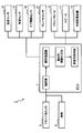
- FIG. 1 is a block diagram showing the configuration of the driver confirmation device.
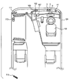
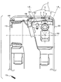
- FIG. 2 is an explanatory diagram showing the arrangement of each component in the bus.
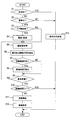
- FIG. 3 is a flowchart showing processing executed by the driver confirmation device.
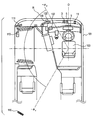
- FIG. 4 is an explanatory diagram showing the visual recognition range R.
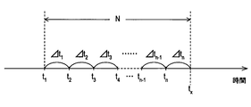
- FIG. 5 is an explanatory diagram showing the accumulated time S
- FIG. 6 is an explanatory diagram showing a method of calculating the accumulated time S.
- FIG. 7 is an explanatory diagram showing the visual recognition range U.
- the driver confirmation device 1 is an in-vehicle device mounted on a bus. As shown in FIG. 1, the driver confirmation device 1 includes a driver camera 3, an illumination 5, an ECU 7, a driver monitor 9, a speaker 11, an external storage device 13, a forwarding sensor 15, a vehicle speed sensor 17, a door opening / closing sensor 19, and a brake. A sensor 21 is provided.
- the bus corresponds to an embodiment of the vehicle.
- the driver camera 3 is installed in front of the driver seat 103 in the bus 101, captures the face of the driver, and acquires the face image.
- the driver camera 3 outputs the acquired face image to the ECU 7.
- the illumination 5 is installed at a position adjacent to the driver camera 3 and irradiates the driver's face with light.
- the illumination 5 enables the driver's face to be photographed even in an environment with low illuminance.
- the ECU 7 is composed of a well-known computer and executes processing to be described later. That is, the ECU 7 has a function of receiving a face image acquired by the driver camera 3, a function of recognizing the face image by a known image recognition method, a function of extracting the face direction of the driver and the direction of the line of sight. And a function of performing passenger visual determination.
- the passenger visual determination represents a determination as to whether or not the driver's face direction or line-of-sight direction is within a predetermined range. Details will be described later.
- the driver monitor 9 is a monitor installed in front of the driver seat 103 as shown in FIG.
- the driver monitor 9 can display various images to the driver.
- the speaker 11 is installed in front of the driver seat 103 as shown in FIG.
- the speaker 11 can output various sounds in the bus 101.
- External storage device 13 is a storage device composed of a hard disk drive.
- the forwarding sensor 15 is a sensor that detects ON / OFF of a display device (not shown) that displays that the bus 101 is in a forwarding state in accordance with the operation of the driver.
- the ON state indicates that the forwarding state is being displayed, and the OFF state indicates that the forwarding state is not displayed.
- the vehicle speed sensor 17 is a sensor that detects the vehicle speed of the bus 101.
- the vehicle speed sensor 17 can also detect that the bus 101 is stopped (that is, the vehicle speed is 0 km / h).
- the door opening / closing sensor 19 is a sensor that detects the opening / closing of the passenger boarding door for the bus 101.
- the brake sensor 21 is a sensor that detects an operating state of a brake in the bus 101.
- the brake to be detected by the brake sensor 21 may be either a foot brake or a side brake.
- the brake corresponds to an embodiment of the braking device.
- an in-vehicle camera 105 In addition to the driver confirmation device 1, in the vehicle of the bus 101, as shown in FIG. 2, an in-vehicle camera 105, an in-vehicle monitor 107, an in-vehicle confirmation mirror 109, a front entrance confirmation mirror 111, a front step confirmation mirror 113 and a middle entrance entrance confirmation mirror 115 are provided.
- the in-vehicle camera 105 is a camera that captures an area where passenger seats are present.
- the in-vehicle monitor 107 is a monitor that displays an image captured by the in-vehicle camera 105.
- the in-vehicle monitor 107 is located on the left front side of the driver seat 103. The driver can see the in-vehicle monitor 107 by facing left front.
- the in-vehicle confirmation mirror 109 is a mirror that reflects the range in which passenger seats are present from the viewpoint of the driver.
- the vehicle interior confirmation mirror 109 is located on the left front side of the driver seat 103. The driver can see the in-vehicle confirmation mirror 109 by facing left front.
- the front entrance / exit confirmation mirror 111 is a mirror that reflects the range in which passenger seats exist from the viewpoint of the driver.
- the front entrance confirmation mirror 111 is located on the left side of the driver seat 103. The driver can see the front entrance entrance confirmation mirror 111 by facing left.
- the confirmation mirror 113 for the previous step is a mirror that reflects a range including a step ahead in the bus 101 as viewed from the driver's viewpoint.
- the front-step confirmation mirror 113 is located on the left side of the driver seat 103. The driver can see the confirmation mirror 113 for the previous step by turning to the left.
- the middle entrance / exit confirmation mirror 115 is a mirror that reflects a range including the middle entrance in the bus 101 from the viewpoint of the driver.
- the middle entrance entrance confirmation mirror 115 is located on the left rear side of the driver seat 103. The driver can see the middle entrance entrance confirmation mirror 115 by facing the left rear.
- the driver camera 3 is an embodiment of a face image acquisition unit (or means)
- the ECU 7 is an extraction unit (or means)
- a first 2 is an embodiment of the determination unit (or means)
- the driver monitor 9 and the speaker 11 are an embodiment of the notification unit (or means)
- the door opening / closing sensor 19 is an embodiment of the detection unit (or means). It is.
- each “unit” can be realized as software as a part of a computer program, or can be realized as hardware using an IC chip or a large-scale integrated circuit.
- processing executed by the driver confirmation device 1 A process that is repeatedly executed by the driver confirmation device 1 (particularly the ECU 7) every predetermined time will be described with reference to FIGS.
- step 1 of FIG. 3 based on the detection signal of the forwarding sensor 15, it is determined whether or not the bus 101 is in a forwarding state (displaying that it is in the forwarding state). If it is not in the forwarding state, the process proceeds to Step 2, and if it is in the forwarding state, the process proceeds to Step 13.
- step 2 based on the detection signal of the vehicle speed sensor 17, it is determined whether or not the bus 101 is stopped. If the vehicle is stopped, the process proceeds to Step 3, and if the vehicle is not stopped (that is, the vehicle is traveling), the process proceeds to Step 13.
- step 3 based on the detection signal of the door opening / closing sensor 19, it is determined whether or not the door of the bus 101 has been opened / closed in a time period from the execution time of step 3 to a predetermined time. If the opening / closing operation has been performed, the process proceeds to step 4. If the opening / closing operation has not been performed, the process proceeds to step 5.
- step 4 the value of the threshold value T is changed from the normal value T 1 to the larger value T 2 .
- the threshold value T is a value used in step 10 described later.
- step 5 the driver's face is photographed using the driver camera 3, and the face image is acquired. At this time, the illumination 5 is used to irradiate the driver's face with light. The acquired face image is output to the ECU 7.
- step 6 a known image recognition process is performed on the face image acquired in step 5 to extract the driver's face direction and the driver's line-of-sight direction.
- step 7 it is determined whether or not at least one of the driver's face orientation extracted in step 6 and the driver's line of sight is within the viewing range R shown in FIG.
- FIG. 4 is a view of the bus 101 as viewed from above.
- the forward direction from the driver seat 103 is 0 degree
- the clockwise angle around the driver seat 103 is an angle r.
- the viewing range R is a range where the angle r is from ⁇ 1 to ⁇ 2 .
- the visual recognition range R includes an in-vehicle monitor 107, an in-vehicle confirmation mirror 109, a front entrance confirmation mirror 111, a front step confirmation mirror 113, and a middle entrance confirmation mirror 115. That is, the viewing range R is a preset range in which the driver can visually recognize the passengers on the bus 101.
- step 8 the cumulative time S in which the driver's face direction or line-of-sight direction is within the viewing range R in the past N seconds is calculated.
- the accumulated time S will be described with reference to FIG.
- the horizontal axis in FIG. 5 represents time, and the further to the right, the later time.
- t x is the time when step 8 is executed.
- t 1 , t 2 , t 3 ... t n are times at which the processing of step 7 is executed for N seconds that go back from t x .
- an accumulated time S that is estimated that the driver's face direction or line-of-sight direction was within the viewing range R is calculated for N seconds retroactive from t x using the formula shown in FIG.
- ⁇ multiplied by ⁇ t i is a variable that is 1 if the result of step 7 executed at time t i is affirmative and 0 if negative.
- step 9 based on the detection signal of the brake sensor 21, it is determined whether or not the brake has been released (corresponding to whether or not the bus 101 has been prepared for departure). If the brake is released, the process proceeds to step 10, and if not, the process proceeds to step 5.
- step 10 it is determined whether or not the accumulated time S calculated in step 8 is greater than a threshold value T.
- the value of the threshold T is T 2 when the process of step 4 is executed, and is T 1 otherwise. If the accumulated time S is less than or equal to the threshold T, the process proceeds to step 11, and if the accumulated time S exceeds the threshold T, this process ends.
- step 11 an alarm sound is generated using the speaker 11, and a warning display is displayed on the driver monitor 9, “Did you confirm passengers before departure”? These alarm sounds and warning indications are an embodiment of notification.
- step 12 the driver's face image acquired while the bus 101 is stopped is stored in the external storage device 13.
- step 2 the process proceeds to step 13 and the running process is executed. An outline of the process during traveling will be described.
- the driver's face direction and line-of-sight direction are extracted. Then, in the same manner as in Steps 7 and 8, the accumulated time during which the driver's face direction or line-of-sight direction is within the predetermined visual recognition range U in the past N seconds is calculated.
- the visual recognition range U in this case is shown in FIG. 7, and the angle r is a range from ⁇ 1 to ⁇ 2 . Where 0 ° ⁇ 1, ⁇ 2 ⁇ 90 degrees.
- the visual recognition range U is a range including the front of the bus 101, and includes the driver monitor 9, but the in-vehicle monitor 107, the in-vehicle confirmation mirror 109, the front entrance confirmation mirror 111, and the front step confirmation mirror. 113 and the middle entrance entrance confirmation mirror 115 are not included.
- a warning for aside driving is performed using the speaker 11 and the driver monitor 9. Further, in the process during running, a parameter corresponding to the driver's drowsiness (for example, an eye opening amount of the driver's eyes) is extracted from the driver's face image by a well-known image recognition method. 11 and the driver monitor 9 are used to give a warning of drowsy driving.
- 3. Effects exhibited by the driver confirmation device 1) (1) The driver confirmation device 1 determines whether or not the driver's face direction or line-of-sight direction is within the visual recognition range R when the vehicle is stopped (that is, whether or not the driver has confirmed the passenger's state while the vehicle is stopped). it can. Therefore, according to the driver confirmation device 1, when the driver tries to depart without confirming the passenger's state while the vehicle is stopped, this can be detected, so the safety of the bus 101 is improved.
- the driver confirmation device 1 determines whether or not the accumulated time S exceeds the threshold T, and if it is equal to or less than the threshold T, alerts the driver. As a result, the safety of the bus 101 is further improved.
- the driver confirmation device 1 increases the threshold value T, and further executes the processing of steps 11 and 12 above. Make it easy to be. Therefore, the safety of the bus 101 is further improved.
- the driver confirmation device 1 stores the driver's face image in the external storage device 13 when the driver tries to depart without sufficiently confirming the state of the passenger while the vehicle is stopped.
- the driver's face image can be used for driver's safe driving education.
- step 6 the driver confirmation device 1 may extract only one of the driver's face direction and the line-of-sight direction. Then, in step 8, it may be determined whether one of them is within the viewing range R.
- the accumulated time S may be calculated by accumulating the time during which both the driver's face direction and the line-of-sight direction are within the viewing range R.
- the value of the threshold value T may be always the same regardless of the detection signal of the door opening / closing sensor 19.
- a sensor that directly detects the presence of passengers for example, a pressure sensor provided on the floor of the bus 101, an infrared sensor provided on the wall of the bus 101, etc.
- a sensor that directly detects the presence of passengers for example, a pressure sensor provided on the floor of the bus 101, an infrared sensor provided on the wall of the bus 101, etc.
- step 8 the cumulative time during which the driver's face direction or line-of-sight direction is within the viewing range R is calculated for the entire parked time period, not limited to the past N seconds. Good.
- the driver confirmation device 1 may be applied to vehicles other than buses (for example, passenger cars, trucks, etc.).
- the visual recognition range R may not include the in-vehicle monitor 107 but may be a range including the in-vehicle confirmation mirror 109, the front entrance confirmation mirror 111, the front step confirmation mirror 113, and the middle entrance confirmation mirror 115.
- the visual recognition range R may include the in-vehicle monitor 107, and may be a range that does not include the in-vehicle confirmation mirror 109, the front entrance confirmation mirror 111, the front step confirmation mirror 113, and the middle entrance confirmation mirror 115.
- a driver confirmation device extracts a driver's face direction and / or line-of-sight direction based on a face image acquisition unit that acquires a face image of a driver of a vehicle and a face image acquired while the vehicle is stopped And a first determination unit that determines whether the face direction and / or the direction of the line of sight is within a preset viewing range in which the passengers of the vehicle can be viewed.
- the driver confirmation device it is possible to determine whether or not the driver's face direction and / or line-of-sight direction when the vehicle is stopped are within the viewing range. That is, it can be determined whether or not the driver has confirmed the state of the passenger while the vehicle is stopped.
- the driver confirmation device when the driver tries to depart without confirming the state of the passenger while the vehicle is stopped, the fact can be detected, so that the safety of the vehicle is improved.
Abstract
An embodiment of the present disclosure provides a driver confirmation device (1) provided with: a facial image acquisition unit (3) that acquires a facial image of a driver of a vehicle (101); an extraction unit (7) that, on the basis of the facial image acquired by the facial image acquisition unit (3) when the vehicle (101) is stopped, extracts a facial direction and/or a line of sight direction of the driver; and a first determination unit (7) that determines whether the facial direction and/or the line of sight direction extracted by the extraction unit (7) is within a preset visual recognition range enabling visual recognition of a passenger in the vehicle (101).
Description
本出願は、2013年5月21日に出願された日本国特許出願2013-107117号に基づくものであり、ここにその記載内容を参照により援用する。
This application is based on Japanese Patent Application No. 2013-107117 filed on May 21, 2013, the contents of which are incorporated herein by reference.
本開示はドライバ確認装置に関する。
This disclosure relates to a driver confirmation device.
路線バス等が発車したとき、着座せず、手すりやつり革を持っていない乗客は転倒してしまうおそれがある。バスの事故については、対車、対歩行者の事故よりも、乗客の転倒事故の方が多い。
When a route bus departs, passengers who are not seated and do not have handrails or straps may fall over. As for bus accidents, there are more passenger accidents than car and pedestrian accidents.
特許文献1には、乗客が着座しているか否かを判定し、その判定結果に応じてバスの走行状態を調整することで、乗客の転倒事故を抑制しようとする技術が開示されている。
Patent Document 1 discloses a technique for determining whether or not a passenger is seated, and adjusting the traveling state of the bus according to the determination result to suppress a passenger's fall accident.
本願発明者は、着座せず、手すりやつり革を持っていない乗客が存在する状態で発車すると、特許文献1記載の技術のように、バスの走行状態を調整したとしても、乗客の転倒事故を十分に抑制することは困難であることを見出した。
The inventor of the present application, when leaving the vehicle in a state where there are passengers who do not sit down and do not have handrails or straps, even if the traveling state of the bus is adjusted as in the technique described in Patent Document 1, the accident of the passenger falling It has been found that it is difficult to sufficiently suppress this.
本開示は以上の点に鑑みなされたものであり、車両の安全性を向上させることができるドライバ確認装置を提供することを目的とする。
The present disclosure has been made in view of the above points, and an object thereof is to provide a driver confirmation device capable of improving the safety of a vehicle.
本開示の実施形態によると車両のドライバの顔画像を取得する顔画像取得部と、車両の停車中に取得した顔画像に基づき、ドライバの顔向き及び/又は視線の方向を抽出する抽出部と、顔向き及び/又は視線の方向が、車両の乗客を視認可能な、予め設定された視認範囲の中にあるか否かを判断する第1判断部とを備えるドライバ確認装置が提供される。
According to an embodiment of the present disclosure, a face image acquisition unit that acquires a face image of a driver of a vehicle, and an extraction unit that extracts a driver's face direction and / or line-of-sight direction based on the face image acquired while the vehicle is stopped There is provided a driver confirmation device including a first determination unit that determines whether a face direction and / or a line-of-sight direction is within a preset viewing range in which a passenger of a vehicle can be visually recognized.
本開示のドライバ確認装置によれば、停車中におけるドライバの顔向き及び/又は視線の方向が視認範囲の中にあったか否かを判断できる。すなわち、ドライバが停車中に乗客の状態を確認したか否かを判断できる。
According to the driver confirmation device of the present disclosure, it can be determined whether or not the driver's face direction and / or line-of-sight direction is within the viewing range when the vehicle is stopped. That is, it can be determined whether or not the driver has confirmed the state of the passenger while the vehicle is stopped.
そのため、本開示のドライバ確認装置によれば、ドライバが停車中に乗客の状態を確認しないまま、発車しようとした場合、そのことを検出できるため、車両の安全性が向上する。
Therefore, according to the driver confirmation device of the present disclosure, when the driver tries to depart without confirming the state of the passenger while the vehicle is stopped, it can be detected, so that the safety of the vehicle is improved.
本開示についての上記および他の目的、特徴や利点は、添付図面を参照した下記詳細な説明から、より明確になる。添付図面において
図1は、ドライバ確認装置の構成を表すブロック図であり、
図2は、バスにおける各構成の配置を表す説明図であり、
図3は、ドライバ確認装置が実行する処理を表すフローチャートであり、
図4は、視認範囲Rを表す説明図であり、
図5は、累積時間Sを表す説明図であり、
図6は、累積時間Sを算出する方法を表す説明図であり、
図7は、視認範囲Uを表す説明図である。
The above and other objects, features, and advantages of the present disclosure will become more apparent from the following detailed description with reference to the accompanying drawings. In the attached drawings
FIG. 1 is a block diagram showing the configuration of the driver confirmation device. FIG. 2 is an explanatory diagram showing the arrangement of each component in the bus. FIG. 3 is a flowchart showing processing executed by the driver confirmation device. FIG. 4 is an explanatory diagram showing the visual recognition range R. FIG. 5 is an explanatory diagram showing the accumulated time S, FIG. 6 is an explanatory diagram showing a method of calculating the accumulated time S. FIG. 7 is an explanatory diagram showing the visual recognition range U.
本開示の実施形態を図面に基づき説明する。
(1.ドライバ確認装置1の構成)
ドライバ確認装置1の構成を図1、及び図2に基づき説明する。ドライバ確認装置1は、バスに搭載される車載装置である。ドライバ確認装置1は、図1に示すように、ドライバ用カメラ3、照明5、ECU7、ドライバモニタ9、スピーカ11、外部記憶装置13、回送センサ15、車速センサ17、ドア開閉センサ19、及びブレーキセンサ21を備える。なお、バスは車両の一実施形態に相当する。 An embodiment of the present disclosure will be described with reference to the drawings.
(1. Configuration of the driver confirmation device 1)
The configuration of thedriver confirmation device 1 will be described with reference to FIGS. 1 and 2. The driver confirmation device 1 is an in-vehicle device mounted on a bus. As shown in FIG. 1, the driver confirmation device 1 includes a driver camera 3, an illumination 5, an ECU 7, a driver monitor 9, a speaker 11, an external storage device 13, a forwarding sensor 15, a vehicle speed sensor 17, a door opening / closing sensor 19, and a brake. A sensor 21 is provided. The bus corresponds to an embodiment of the vehicle.
(1.ドライバ確認装置1の構成)
ドライバ確認装置1の構成を図1、及び図2に基づき説明する。ドライバ確認装置1は、バスに搭載される車載装置である。ドライバ確認装置1は、図1に示すように、ドライバ用カメラ3、照明5、ECU7、ドライバモニタ9、スピーカ11、外部記憶装置13、回送センサ15、車速センサ17、ドア開閉センサ19、及びブレーキセンサ21を備える。なお、バスは車両の一実施形態に相当する。 An embodiment of the present disclosure will be described with reference to the drawings.
(1. Configuration of the driver confirmation device 1)
The configuration of the
ドライバ用カメラ3は、図2に示すように、バス101におけるドライバシート103の前方に設置され、ドライバの顔を撮影し、その顔画像を取得する。ドライバ用カメラ3は、取得した顔画像をECU7に出力する。
As shown in FIG. 2, the driver camera 3 is installed in front of the driver seat 103 in the bus 101, captures the face of the driver, and acquires the face image. The driver camera 3 outputs the acquired face image to the ECU 7.
照明5は、ドライバ用カメラ3と隣接する位置に設置され、ドライバの顔に光を照射する。照明5により、照度が低い環境においても、ドライバの顔の撮影が可能になる。ECU7は周知のコンピュータにより構成され、後述する処理を実行する。すなわち、ECU7は、ドライバ用カメラ3により取得された顔画像を受け取る機能と、周知の画像認識の方法により顔画像の認識を行う機能と、ドライバの顔向き、及び視線の方向を抽出する機能と、乗客目視判定を行う機能とを有する。なお、乗客目視判定は、ドライバの顔向き又は視線の方向が所定の範囲内にあるか否かの判定を表す。詳しくは後述する。
The illumination 5 is installed at a position adjacent to the driver camera 3 and irradiates the driver's face with light. The illumination 5 enables the driver's face to be photographed even in an environment with low illuminance. The ECU 7 is composed of a well-known computer and executes processing to be described later. That is, the ECU 7 has a function of receiving a face image acquired by the driver camera 3, a function of recognizing the face image by a known image recognition method, a function of extracting the face direction of the driver and the direction of the line of sight. And a function of performing passenger visual determination. The passenger visual determination represents a determination as to whether or not the driver's face direction or line-of-sight direction is within a predetermined range. Details will be described later.
ドライバモニタ9は、図2に示すように、ドライバシート103の前方に設置されたモニタである。ドライバモニタ9は種々の画像をドライバに対し表示可能である。スピーカ11は、図2に示すように、ドライバシート103の前方に設置されている。スピーカ11は、バス101の車内において種々の音声を出力可能である。
The driver monitor 9 is a monitor installed in front of the driver seat 103 as shown in FIG. The driver monitor 9 can display various images to the driver. The speaker 11 is installed in front of the driver seat 103 as shown in FIG. The speaker 11 can output various sounds in the bus 101.
外部記憶装置13はハードディスクドライブにより構成される記憶装置である。回送センサ15は、ドライバの操作に応じてバス101が回送の状態であることを表示する表示装置(図示略)のON/OFFを検出するセンサである。なお、ONの状態は、回送の状態であることを表示中であることをあらわし、OFFの状態は、回送の状態であることを表示していないことをあらわす。
External storage device 13 is a storage device composed of a hard disk drive. The forwarding sensor 15 is a sensor that detects ON / OFF of a display device (not shown) that displays that the bus 101 is in a forwarding state in accordance with the operation of the driver. The ON state indicates that the forwarding state is being displayed, and the OFF state indicates that the forwarding state is not displayed.
車速センサ17は、バス101の車速を検出するセンサである。車速センサ17は、バス101が停車中であること(すなわち、車速が0Km/hであること)も検出可能である。
The vehicle speed sensor 17 is a sensor that detects the vehicle speed of the bus 101. The vehicle speed sensor 17 can also detect that the bus 101 is stopped (that is, the vehicle speed is 0 km / h).
ドア開閉センサ19は、バス101の乗客乗降用ドアの開閉を検出するセンサである。ブレーキセンサ21は、バス101におけるブレーキの作動状態を検出するセンサである。ブレーキセンサ21の検出対象となるブレーキはフットブレーキ、サイドブレーキのいずれであってもよい。なお、ブレーキは制動装置の一実施形態に相当する。
The door opening / closing sensor 19 is a sensor that detects the opening / closing of the passenger boarding door for the bus 101. The brake sensor 21 is a sensor that detects an operating state of a brake in the bus 101. The brake to be detected by the brake sensor 21 may be either a foot brake or a side brake. The brake corresponds to an embodiment of the braking device.
なお、バス101の車内には、ドライバ確認装置1の他にも、図2に示すように、車内カメラ105、車内モニタ107、車内確認ミラー109、前出入口用確認ミラー111、前ステップ用確認ミラー113、及び中出入口用確認ミラー115が設けられている。
In addition to the driver confirmation device 1, in the vehicle of the bus 101, as shown in FIG. 2, an in-vehicle camera 105, an in-vehicle monitor 107, an in-vehicle confirmation mirror 109, a front entrance confirmation mirror 111, a front step confirmation mirror 113 and a middle entrance entrance confirmation mirror 115 are provided.
車内カメラ105は、乗客用のシートが存在する範囲を撮影するカメラである。車内モニタ107は、車内カメラ105で撮影した画像を表示するモニタである。車内モニタ107はドライバシート103の左前方に位置する。ドライバは、左前方を向くことで、車内モニタ107を見ることができる。
The in-vehicle camera 105 is a camera that captures an area where passenger seats are present. The in-vehicle monitor 107 is a monitor that displays an image captured by the in-vehicle camera 105. The in-vehicle monitor 107 is located on the left front side of the driver seat 103. The driver can see the in-vehicle monitor 107 by facing left front.
車内確認ミラー109は、ドライバの視点から見て、乗客用のシートが存在する範囲を映す鏡である。車内確認ミラー109はドライバシート103の左前方に位置する。ドライバは、左前方を向くことで、車内確認ミラー109を見ることができる。
The in-vehicle confirmation mirror 109 is a mirror that reflects the range in which passenger seats are present from the viewpoint of the driver. The vehicle interior confirmation mirror 109 is located on the left front side of the driver seat 103. The driver can see the in-vehicle confirmation mirror 109 by facing left front.
前出入口用確認ミラー111は、ドライバの視点から見て、乗客用のシートが存在する範囲を映す鏡である。前出入口用確認ミラー111はドライバシート103の左方に位置する。ドライバは、左方を向くことで、前出入口用確認ミラー111を見ることができる。
The front entrance / exit confirmation mirror 111 is a mirror that reflects the range in which passenger seats exist from the viewpoint of the driver. The front entrance confirmation mirror 111 is located on the left side of the driver seat 103. The driver can see the front entrance entrance confirmation mirror 111 by facing left.
前ステップ用確認ミラー113は、ドライバの視点から見て、バス101における前方のステップを含む範囲を映す鏡である。前ステップ用確認ミラー113はドライバシート103の左方に位置する。ドライバは、左方を向くことで、前ステップ用確認ミラー113を見ることができる。
The confirmation mirror 113 for the previous step is a mirror that reflects a range including a step ahead in the bus 101 as viewed from the driver's viewpoint. The front-step confirmation mirror 113 is located on the left side of the driver seat 103. The driver can see the confirmation mirror 113 for the previous step by turning to the left.
中出入口用確認ミラー115は、ドライバの視点から見て、バス101における中出入口を含む範囲を映す鏡である。中出入口用確認ミラー115はドライバシート103の左後方に位置する。ドライバは、左後方を向くことで、中出入口用確認ミラー115を見ることができる。
The middle entrance / exit confirmation mirror 115 is a mirror that reflects a range including the middle entrance in the bus 101 from the viewpoint of the driver. The middle entrance entrance confirmation mirror 115 is located on the left rear side of the driver seat 103. The driver can see the middle entrance entrance confirmation mirror 115 by facing the left rear.
なお、ドライバ用カメラ3は顔画像取得部(または手段)の一実施形態であり、ECU7は抽出部(または手段)、第1の判断部(または手段)、算出部(または手段)、及び第2の判断部(または手段)の一実施形態であり、ドライバモニタ9及びスピーカ11は報知部(または手段)の一実施形態であり、ドア開閉センサ19は検出部(または手段)の一実施形態である。
これらの「部」は、ECU7が有する機能に着目してECU7の内部を便宜的に分類したものであり、ECU7の内部が、それぞれの「部」に対応する部分に物理的に区分されていることを意味するものではない。従って、それぞれの「部」は、コンピュータープログラムの一部分としてソフトウェア的に実現することもできるし、ICチップや大規模集積回路によってハードウェア的に実現することもできる。
(2.ドライバ確認装置1が実行する処理)
ドライバ確認装置1(特にECU7)が所定時間ごとに繰り返し実行する処理を図3~図7に基づき説明する。図3のステップ1において、回送センサ15の検出信号に基づき、バス101が回送の状態(回送の状態にあることを表示中)であるか否かを判断する。回送の状態ではない場合はステップ2に進み、回送の状態である場合はステップ13に進む。 Thedriver camera 3 is an embodiment of a face image acquisition unit (or means), and the ECU 7 is an extraction unit (or means), a first determination unit (or means), a calculation unit (or means), and a first 2 is an embodiment of the determination unit (or means), the driver monitor 9 and the speaker 11 are an embodiment of the notification unit (or means), and the door opening / closing sensor 19 is an embodiment of the detection unit (or means). It is.
These “parts” are obtained by classifying the inside of the ECU 7 for convenience, focusing on the functions of the ECU 7, and the inside of the ECU 7 is physically divided into parts corresponding to the respective “parts”. It doesn't mean that. Accordingly, each “unit” can be realized as software as a part of a computer program, or can be realized as hardware using an IC chip or a large-scale integrated circuit.
(2. Processing executed by the driver confirmation device 1)
A process that is repeatedly executed by the driver confirmation device 1 (particularly the ECU 7) every predetermined time will be described with reference to FIGS. Instep 1 of FIG. 3, based on the detection signal of the forwarding sensor 15, it is determined whether or not the bus 101 is in a forwarding state (displaying that it is in the forwarding state). If it is not in the forwarding state, the process proceeds to Step 2, and if it is in the forwarding state, the process proceeds to Step 13.
これらの「部」は、ECU7が有する機能に着目してECU7の内部を便宜的に分類したものであり、ECU7の内部が、それぞれの「部」に対応する部分に物理的に区分されていることを意味するものではない。従って、それぞれの「部」は、コンピュータープログラムの一部分としてソフトウェア的に実現することもできるし、ICチップや大規模集積回路によってハードウェア的に実現することもできる。
(2.ドライバ確認装置1が実行する処理)
ドライバ確認装置1(特にECU7)が所定時間ごとに繰り返し実行する処理を図3~図7に基づき説明する。図3のステップ1において、回送センサ15の検出信号に基づき、バス101が回送の状態(回送の状態にあることを表示中)であるか否かを判断する。回送の状態ではない場合はステップ2に進み、回送の状態である場合はステップ13に進む。 The
These “parts” are obtained by classifying the inside of the ECU 7 for convenience, focusing on the functions of the ECU 7, and the inside of the ECU 7 is physically divided into parts corresponding to the respective “parts”. It doesn't mean that. Accordingly, each “unit” can be realized as software as a part of a computer program, or can be realized as hardware using an IC chip or a large-scale integrated circuit.
(2. Processing executed by the driver confirmation device 1)
A process that is repeatedly executed by the driver confirmation device 1 (particularly the ECU 7) every predetermined time will be described with reference to FIGS. In
ステップ2では、車速センサ17の検出信号に基づき、バス101が停車中であるか否かを判断する。停車中である場合はステップ3に進み、停車中ではない(すなわち、走行中である)場合はステップ13に進む。
In step 2, based on the detection signal of the vehicle speed sensor 17, it is determined whether or not the bus 101 is stopped. If the vehicle is stopped, the process proceeds to Step 3, and if the vehicle is not stopped (that is, the vehicle is traveling), the process proceeds to Step 13.
ステップ3では、ドア開閉センサ19の検出信号に基づき、本ステップ3の実行時点から所定時間前までの時間帯に、バス101のドアの開閉が行われたか否かを判断する。開閉が行われた場合はステップ4に進み、開閉が行われなかった場合はステップ5に進む。
In step 3, based on the detection signal of the door opening / closing sensor 19, it is determined whether or not the door of the bus 101 has been opened / closed in a time period from the execution time of step 3 to a predetermined time. If the opening / closing operation has been performed, the process proceeds to step 4. If the opening / closing operation has not been performed, the process proceeds to step 5.
ステップ4では、閾値Tの値を、通常の値であるT1から、それよりも大きい値であるT2に変更する。なお、閾値Tは後述するステップ10で使用する値である。ステップ5では、ドライバ用カメラ3を用いてドライバの顔を撮影し、その顔画像を取得する。このとき、照明5を用いてドライバの顔に光を照射する。取得した顔画像はECU7に出力する。
In step 4, the value of the threshold value T is changed from the normal value T 1 to the larger value T 2 . The threshold value T is a value used in step 10 described later. In step 5, the driver's face is photographed using the driver camera 3, and the face image is acquired. At this time, the illumination 5 is used to irradiate the driver's face with light. The acquired face image is output to the ECU 7.
ステップ6では、前記ステップ5で取得した顔画像に対し、周知の画像認識処理を実行し、ドライバの顔向きと、ドライバの視線の方向とを抽出する。ステップ7では、前記ステップ6で抽出したドライバの顔向きと、ドライバの視線の方向とのうちの少なくとも一方が、図4に示す視認範囲Rの中にあるか否かを判断する。図4は、バス101を上方から見た図である。図4において、ドライバシート103から前方に向う方向を0度とし、ドライバシート103を中心とする時計回り方向の角度を角度rとする。視認範囲Rは、この角度rが-α1から-α2までの範囲である。ここで、0度<α2<α1<180度である。
In step 6, a known image recognition process is performed on the face image acquired in step 5 to extract the driver's face direction and the driver's line-of-sight direction. In step 7, it is determined whether or not at least one of the driver's face orientation extracted in step 6 and the driver's line of sight is within the viewing range R shown in FIG. FIG. 4 is a view of the bus 101 as viewed from above. In FIG. 4, the forward direction from the driver seat 103 is 0 degree, and the clockwise angle around the driver seat 103 is an angle r. The viewing range R is a range where the angle r is from −α 1 to −α 2 . Here, 0 degrees <α 2 <α 1 <180 degrees.
視認範囲Rには、車内モニタ107、車内確認ミラー109、前出入口用確認ミラー111、前ステップ用確認ミラー113、及び中出入口用確認ミラー115が含まれる。すなわち、視認範囲Rは、ドライバがバス101の乗客を視認可能な、予め設定された範囲である。
The visual recognition range R includes an in-vehicle monitor 107, an in-vehicle confirmation mirror 109, a front entrance confirmation mirror 111, a front step confirmation mirror 113, and a middle entrance confirmation mirror 115. That is, the viewing range R is a preset range in which the driver can visually recognize the passengers on the bus 101.
ステップ8では、過去のN秒間のうち、ドライバの顔向き又は視線の方向が視認範囲Rの中にあった累積時間Sを算出する。この累積時間Sを図5に基いて説明する。図5の横軸は時間を表し、右にゆくほど後の時間を表す。図5においてtxは、本ステップ8を実行する時刻である。t1、t2、t3・・・tnは、それぞれ、txから遡るN秒間に、前記ステップ7の処理を実行した時刻である。また、Δtiは、tiからti+1までの時間である(i=1、2、3・・・n-1)。
In step 8, the cumulative time S in which the driver's face direction or line-of-sight direction is within the viewing range R in the past N seconds is calculated. The accumulated time S will be described with reference to FIG. The horizontal axis in FIG. 5 represents time, and the further to the right, the later time. In FIG. 5, t x is the time when step 8 is executed. t 1 , t 2 , t 3 ... t n are times at which the processing of step 7 is executed for N seconds that go back from t x . Δt i is the time from t i to t i + 1 (i = 1, 2, 3,... N−1).
tiにおいて、ドライバの顔向き又は視線の方向が視認範囲Rの中にあった場合(ステップ7において肯定判断をした場合に相当)は、tiからti+1までの間(Δtiの間)、ドライバの顔向き又は視線の方向が視認範囲Rの中にあったと推定する。一方、tiにおいて、ドライバの顔向き及び視線の方向が視認範囲Rの中になかった場合(前記ステップ7において否定判断をした場合)は、tiからti+1までの間(Δtiの間)、ドライバの顔向き及び視線の方向が視認範囲Rの中にはなかったと推定する。
In t i, when the direction of the driver's face direction or gaze was in the visible range R (corresponding to the case where the affirmative determination in step 7), between the t i to t i + 1 (a Delta] t i In the meantime, it is estimated that the driver's face direction or line-of-sight direction was in the viewing range R. On the other hand, in t i, the direction of the driver's face direction and line of sight (when the negative determination is made at step 7) if no in the visible range R is between from t i to t i + 1 (Delta] t i It is estimated that the driver's face direction and line-of-sight direction were not within the viewing range R.
そして、図6に示す数式により、txから遡るN秒間において、ドライバの顔向き又は視線の方向が視認範囲Rの中にあったと推定される累積時間Sを算出する。図6においてΔtiに乗算されるεは、時刻tiにおいて実行した前記ステップ7の結果が肯定判断であれば1であり、否定判断であれば0となる変数である。
Then, an accumulated time S that is estimated that the driver's face direction or line-of-sight direction was within the viewing range R is calculated for N seconds retroactive from t x using the formula shown in FIG. In FIG. 6, ε multiplied by Δt i is a variable that is 1 if the result of step 7 executed at time t i is affirmative and 0 if negative.
ステップ9では、ブレーキセンサ21の検出信号に基づき、ブレーキが解除されたか否か(バス101の発車準備が行われたか否かに相当)を判断する。ブレーキが解除された場合はステップ10に進み、解除されていない場合はステップ5に進む。
In step 9, based on the detection signal of the brake sensor 21, it is determined whether or not the brake has been released (corresponding to whether or not the bus 101 has been prepared for departure). If the brake is released, the process proceeds to step 10, and if not, the process proceeds to step 5.
ステップ10では、前記ステップ8で算出した累積時間Sが、閾値Tより大きいか否かを判断する。なお、閾値Tの値は、前記ステップ4の処理を実行した場合はT2であり、それ以外の場合はT1である。累積時間Sが閾値T以下である場合はステップ11に進み、閾値Tを超える場合は本処理を終了する。
In step 10, it is determined whether or not the accumulated time S calculated in step 8 is greater than a threshold value T. Note that the value of the threshold T is T 2 when the process of step 4 is executed, and is T 1 otherwise. If the accumulated time S is less than or equal to the threshold T, the process proceeds to step 11, and if the accumulated time S exceeds the threshold T, this process ends.
ステップ11では、スピーカ11を用いて警報音を発するとともに、ドライバモニタ9に「発車前に乗客を確認しましたか」という警告表示を行う。なお、これらの警報音及び警告表示は、報知の一実施形態である。
In step 11, an alarm sound is generated using the speaker 11, and a warning display is displayed on the driver monitor 9, “Did you confirm passengers before departure”? These alarm sounds and warning indications are an embodiment of notification.
ステップ12では、バス101の停車中に取得したドライバの顔画像を外部記憶装置13に記憶する。一方、前記ステップ1又はステップ2で否定判断した場合はステップ13に進み、走行中の処理を実行する。この走行中の処理の概略を説明する。
In step 12, the driver's face image acquired while the bus 101 is stopped is stored in the external storage device 13. On the other hand, if a negative determination is made in step 1 or step 2, the process proceeds to step 13 and the running process is executed. An outline of the process during traveling will be described.
まず、前記ステップ5、6と同様に、ドライバの顔向き及び視線の方向を抽出する。そして、前記ステップ7、8と基本的には同様にして、過去N秒間において、ドライバの顔向き又は視線の方向が所定の視認範囲Uの中にあった累積時間を算出する。
First, as in steps 5 and 6, the driver's face direction and line-of-sight direction are extracted. Then, in the same manner as in Steps 7 and 8, the accumulated time during which the driver's face direction or line-of-sight direction is within the predetermined visual recognition range U in the past N seconds is calculated.
ただし、この場合の視認範囲Uは、図7に示すものであって、角度rが-β1からβ2までの範囲である。ここで、0度<β1、β2<90度である。視認範囲Uは、バス101の前方を含む範囲であって、その中には、ドライバモニタ9は含まれるが、車内モニタ107、車内確認ミラー109、前出入口用確認ミラー111、前ステップ用確認ミラー113、及び中出入口用確認ミラー115は含まれない。
However, the visual recognition range U in this case is shown in FIG. 7, and the angle r is a range from −β 1 to β 2 . Where 0 ° <β 1, β 2 <90 degrees. The visual recognition range U is a range including the front of the bus 101, and includes the driver monitor 9, but the in-vehicle monitor 107, the in-vehicle confirmation mirror 109, the front entrance confirmation mirror 111, and the front step confirmation mirror. 113 and the middle entrance entrance confirmation mirror 115 are not included.
走行中の処理において、累積時間が所定の閾値以下であると、スピーカ11及びドライバモニタ9を用いて脇見運転の警告を行う。また、走行中の処理において、ドライバの顔画像から、周知の画像認識の方法で、ドライバの眠気に対応するパラメータ(例えばドライバの目の開眼量等)を抽出し、眠気を検出した場合はスピーカ11及びドライバモニタ9を用いて居眠り運転の警告を行う。
(3.ドライバ確認装置1が奏する効果)
(1)ドライバ確認装置1は、停車中におけるドライバの顔向き又は視線の方向が視認範囲Rの中にあったか否か(すなわち、停車中にドライバが乗客の状態を確認したか否か)を判断できる。そのため、ドライバ確認装置1によれば、ドライバが停車中に乗客の状態を確認しないまま、発車しようとした場合、そのことを検出できるため、バス101の安全性が向上する。 In the running process, if the accumulated time is equal to or less than a predetermined threshold value, a warning for aside driving is performed using thespeaker 11 and the driver monitor 9. Further, in the process during running, a parameter corresponding to the driver's drowsiness (for example, an eye opening amount of the driver's eyes) is extracted from the driver's face image by a well-known image recognition method. 11 and the driver monitor 9 are used to give a warning of drowsy driving.
(3. Effects exhibited by the driver confirmation device 1)
(1) Thedriver confirmation device 1 determines whether or not the driver's face direction or line-of-sight direction is within the visual recognition range R when the vehicle is stopped (that is, whether or not the driver has confirmed the passenger's state while the vehicle is stopped). it can. Therefore, according to the driver confirmation device 1, when the driver tries to depart without confirming the passenger's state while the vehicle is stopped, this can be detected, so the safety of the bus 101 is improved.
(3.ドライバ確認装置1が奏する効果)
(1)ドライバ確認装置1は、停車中におけるドライバの顔向き又は視線の方向が視認範囲Rの中にあったか否か(すなわち、停車中にドライバが乗客の状態を確認したか否か)を判断できる。そのため、ドライバ確認装置1によれば、ドライバが停車中に乗客の状態を確認しないまま、発車しようとした場合、そのことを検出できるため、バス101の安全性が向上する。 In the running process, if the accumulated time is equal to or less than a predetermined threshold value, a warning for aside driving is performed using the
(3. Effects exhibited by the driver confirmation device 1)
(1) The
(2)ドライバ確認装置1は、累積時間Sが閾値Tを超えるか否かを判断し、閾値T以下である場合はドライバに対し注意喚起を行う。その結果、バス101の安全性が一層向上する。
(2) The driver confirmation device 1 determines whether or not the accumulated time S exceeds the threshold T, and if it is equal to or less than the threshold T, alerts the driver. As a result, the safety of the bus 101 is further improved.
(3)ドライバ確認装置1は、バス101のドアの開閉が行われた場合(乗降客が居る可能性がある場合)、閾値Tの値を大きくし、前記ステップ11、12の処理が一層実行されやすいようにする。そのため、バス101の安全性が一層向上する。
(3) When the door of the bus 101 is opened and closed (when there is a possibility that there are passengers), the driver confirmation device 1 increases the threshold value T, and further executes the processing of steps 11 and 12 above. Make it easy to be. Therefore, the safety of the bus 101 is further improved.
(4)ドライバ確認装置1は、ドライバが停車中に乗客の状態を十分確認しないまま、発車しようとした場合、ドライバの顔画像を外部記憶装置13に記憶する。ドライバの顔画像は、ドライバの安全運転教育に利用できる。
(4) The driver confirmation device 1 stores the driver's face image in the external storage device 13 when the driver tries to depart without sufficiently confirming the state of the passenger while the vehicle is stopped. The driver's face image can be used for driver's safe driving education.
(5)ドライバ確認装置1は、回送の状態にある場合は前記ステップ2~12の処理を実行しない。そのため、無駄な処理を行わなくて済む。
(4.変形例)
(1)ドライバ確認装置1は、前記ステップ6において、ドライバの顔向きと、視線の方向とのうち、一方のみを抽出してもよい。そして、前記ステップ8において、その一方が視認範囲Rの中にあるか否かを判断してもよい。 (5) Thedriver confirmation device 1 does not execute the processing of steps 2 to 12 when in the forwarding state. Therefore, it is not necessary to perform useless processing.
(4. Modifications)
(1) Instep 6, the driver confirmation device 1 may extract only one of the driver's face direction and the line-of-sight direction. Then, in step 8, it may be determined whether one of them is within the viewing range R.
(4.変形例)
(1)ドライバ確認装置1は、前記ステップ6において、ドライバの顔向きと、視線の方向とのうち、一方のみを抽出してもよい。そして、前記ステップ8において、その一方が視認範囲Rの中にあるか否かを判断してもよい。 (5) The
(4. Modifications)
(1) In
(2)前記ステップ8において、ドライバの顔向きと、視線の方向との両方が視認範囲Rの中にある時間を累積して累積時間Sを算出しても良い。
(2) In step 8, the accumulated time S may be calculated by accumulating the time during which both the driver's face direction and the line-of-sight direction are within the viewing range R.
(3)閾値Tの値は、ドア開閉センサ19の検出信号によらず、常に同じであってもよい。
(3) The value of the threshold value T may be always the same regardless of the detection signal of the door opening / closing sensor 19.
(4)ドア開閉センサ19に代えて、あるいはそれに加えて、乗降客の存在を直接検出するセンサ(例えばバス101の床面に設けられた圧力センサ、バス101の壁面に設けられた赤外線センサ等)を備えていてもよい。そして、そのセンサで乗降客を直接検出した場合、前記ステップ3で肯定判断をすることができる。
(4) Instead of or in addition to the door opening / closing sensor 19, a sensor that directly detects the presence of passengers (for example, a pressure sensor provided on the floor of the bus 101, an infrared sensor provided on the wall of the bus 101, etc.) ) May be provided. If the passenger is directly detected by the sensor, an affirmative determination can be made in step 3.
(5)前記ステップ8では、過去のN秒間に限定せず、停車している時間帯全体において、ドライバの顔向き又は視線の方向が視認範囲Rの中にあった累積時間を算出してもよい。
(5) In step 8, the cumulative time during which the driver's face direction or line-of-sight direction is within the viewing range R is calculated for the entire parked time period, not limited to the past N seconds. Good.
(6)ドライバ確認装置1は、バス以外の車両(例えば乗用車、トラック等)に適用してもよい。
(6) The driver confirmation device 1 may be applied to vehicles other than buses (for example, passenger cars, trucks, etc.).
(7)視認範囲Rは、車内モニタ107を含まず、車内確認ミラー109、前出入口用確認ミラー111、前ステップ用確認ミラー113、及び中出入口用確認ミラー115を含む範囲であってもよい。また、視認範囲Rは、車内モニタ107を含み、車内確認ミラー109、前出入口用確認ミラー111、前ステップ用確認ミラー113、及び中出入口用確認ミラー115は含まない範囲であってもよい。
(7) The visual recognition range R may not include the in-vehicle monitor 107 but may be a range including the in-vehicle confirmation mirror 109, the front entrance confirmation mirror 111, the front step confirmation mirror 113, and the middle entrance confirmation mirror 115. The visual recognition range R may include the in-vehicle monitor 107, and may be a range that does not include the in-vehicle confirmation mirror 109, the front entrance confirmation mirror 111, the front step confirmation mirror 113, and the middle entrance confirmation mirror 115.
本開示の一例に係るドライバ確認装置は、車両のドライバの顔画像を取得する顔画像取得部と、車両の停車中に取得した顔画像に基づき、ドライバの顔向き及び/又は視線の方向を抽出する抽出部と、顔向き及び/又は視線の方向が、車両の乗客を視認可能な、予め設定された視認範囲の中にあるか否かを判断する第1判断部とを備える。
A driver confirmation device according to an example of the present disclosure extracts a driver's face direction and / or line-of-sight direction based on a face image acquisition unit that acquires a face image of a driver of a vehicle and a face image acquired while the vehicle is stopped And a first determination unit that determines whether the face direction and / or the direction of the line of sight is within a preset viewing range in which the passengers of the vehicle can be viewed.
本開示の一例に係るドライバ確認装置によれば、停車中におけるドライバの顔向き及び/又は視線の方向が視認範囲の中にあったか否かを判断できる。すなわち、ドライバが停車中に乗客の状態を確認したか否かを判断できる。
According to the driver confirmation device according to an example of the present disclosure, it is possible to determine whether or not the driver's face direction and / or line-of-sight direction when the vehicle is stopped are within the viewing range. That is, it can be determined whether or not the driver has confirmed the state of the passenger while the vehicle is stopped.
そのため、本開示の一例に係るドライバ確認装置によれば、ドライバが停車中に乗客の状態を確認しないまま、発車しようとした場合、そのことを検出できるため、車両の安全性が向上する。
Therefore, according to the driver confirmation device according to an example of the present disclosure, when the driver tries to depart without confirming the state of the passenger while the vehicle is stopped, the fact can be detected, so that the safety of the vehicle is improved.
以上、本開示の実施形態、構成、態様を例示したが、本開示に係わる実施形態、構成、態様は、上述した各実施形態、各構成、各態様に限定されるものではない。例えば、異なる実施形態、構成、態様にそれぞれ開示された技術的部を適宜組み合わせて得られる実施形態、構成、態様についても本開示に係わる実施形態、構成、態様の範囲に含まれる。
The embodiments, configurations, and aspects of the present disclosure have been illustrated above, but the embodiments, configurations, and aspects according to the present disclosure are not limited to the above-described embodiments, configurations, and aspects. For example, embodiments, configurations, and aspects obtained by appropriately combining technical units disclosed in different embodiments, configurations, and aspects are also included in the scope of the embodiments, configurations, and aspects according to the present disclosure.
Claims (6)
- 車両(101)のドライバの顔画像を取得する顔画像取得部(3)と、
前記車両(101)の停車中に前記顔画像取得部(3)により取得した前記顔画像に基づき、前記ドライバの顔向き及び/又は視線の方向を抽出する抽出部(7)と、
前記抽出部(7)により抽出した前記顔向き及び/又は視線の方向が、前記車両(101)の乗客を視認可能な、予め設定された視認範囲の中にあるか否かを判断する第1の判断部(7)と、
を備えるドライバ確認装置(1)。 A face image acquisition unit (3) for acquiring a driver's face image of the vehicle (101);
An extraction unit (7) for extracting the driver's face direction and / or line-of-sight direction based on the face image acquired by the face image acquisition unit (3) while the vehicle (101) is stopped;
A first determination is made as to whether or not the face orientation and / or line-of-sight direction extracted by the extraction unit (7) is within a preset viewing range in which a passenger of the vehicle (101) can be visually recognized. A determination unit (7) of
A driver confirmation apparatus (1) comprising: - 前記第1の判断部(7)の判断結果に基づき、前記顔向き及び/又は視線の方向が、前記視認範囲の中にあった累積時間を算出する算出部(7)と、
前記算出部(7)により算出された前記累積時間が所定の閾値を超えるか否かを判断する第2の判断部(7)と、
前記第2の判断部(7)の判断結果に基づき報知を行う報知部(9、11)と、
を備える請求項1に記載のドライバ確認装置(1)。 Based on the determination result of the first determination unit (7), a calculation unit (7) that calculates an accumulated time in which the face direction and / or the direction of the line of sight was within the viewing range;
A second determination unit (7) for determining whether or not the accumulated time calculated by the calculation unit (7) exceeds a predetermined threshold;
A notification unit (9, 11) for performing notification based on the determination result of the second determination unit (7);
The driver confirmation device (1) according to claim 1, comprising: - 前記車両(101)における乗降客の有無、及び/又はドアの開閉の有無を検出する検出部(19)を備え、
前記閾値は、前記乗降客又は前記ドアの開閉が有った場合の方が、それ以外の場合よりも大きい請求項2に記載のドライバ確認装置(1)。 A detector (19) for detecting presence / absence of passengers in the vehicle (101) and / or presence / absence of opening / closing of a door;
The driver confirmation device (1) according to claim 2, wherein the threshold value is greater when the passenger or the door is opened or closed than when the door is opened or closed. - 前記視認範囲は、ドライバの視点から見て前記乗客が映る鏡(109、111、113、115)、及び/又は前記乗客を撮影するカメラ(105)の画像を表示するモニタ(107)を含む範囲である請求項1~3のいずれか1項に記載のドライバ確認装置(1)。 The viewing range includes a mirror (109, 111, 113, 115) in which the passenger is seen from the viewpoint of the driver and / or a monitor (107) that displays an image of the camera (105) that captures the passenger. The driver confirmation device (1) according to any one of claims 1 to 3, wherein:
- 前記第1の判断部(7)は、前記車両(101)が停車中に、前記ドライバの顔向き及び/又は視線の方向が、前記車両(101)の乗客を視認可能な、予め設定された視認範囲の中にあるか否かを判断する請求項1~4のいずれか1項に記載のドライバ確認装置(1)。 The first determination unit (7) is set in advance so that the driver's face direction and / or line-of-sight direction can visually recognize passengers of the vehicle (101) while the vehicle (101) is stopped. The driver confirmation device (1) according to any one of claims 1 to 4, wherein it is determined whether or not it is within a viewing range.
- 前記第2の判断部(7)は、前記車両(101)の制動装置が解除されたとき、前記累積時間が所定の閾値を超えるか否かを判断する請求項2~5のいずれか1項に記載のドライバ確認装置(1)。 The second determination unit (7) determines whether or not the accumulated time exceeds a predetermined threshold when the braking device of the vehicle (101) is released. The driver confirmation apparatus (1) described in 1.
Priority Applications (1)
| Application Number | Priority Date | Filing Date | Title |
|---|---|---|---|
| US14/892,447 US9767374B2 (en) | 2013-05-21 | 2014-04-07 | Driver check apparatus |
Applications Claiming Priority (2)
| Application Number | Priority Date | Filing Date | Title |
|---|---|---|---|
| JP2013-107117 | 2013-05-21 | ||
| JP2013107117A JP5949660B2 (en) | 2013-05-21 | 2013-05-21 | Driver confirmation device |
Publications (1)
| Publication Number | Publication Date |
|---|---|
| WO2014188648A1 true WO2014188648A1 (en) | 2014-11-27 |
Family
ID=51933221
Family Applications (1)
| Application Number | Title | Priority Date | Filing Date |
|---|---|---|---|
| PCT/JP2014/001981 WO2014188648A1 (en) | 2013-05-21 | 2014-04-07 | Driver confirmation device |
Country Status (3)
| Country | Link |
|---|---|
| US (1) | US9767374B2 (en) |
| JP (1) | JP5949660B2 (en) |
| WO (1) | WO2014188648A1 (en) |
Cited By (3)
| Publication number | Priority date | Publication date | Assignee | Title |
|---|---|---|---|---|
| US9767374B2 (en) | 2013-05-21 | 2017-09-19 | Denso Corporation | Driver check apparatus |
| CN110103978A (en) * | 2018-02-01 | 2019-08-09 | 株式会社斯巴鲁 | Occupant's monitoring arrangement of vehicle |
| CN112829755A (en) * | 2021-02-08 | 2021-05-25 | 浙江大学 | System and method for recognizing state of passenger through pressure distribution of foot position of passenger |
Families Citing this family (11)
| Publication number | Priority date | Publication date | Assignee | Title |
|---|---|---|---|---|
| US10445603B1 (en) * | 2015-12-11 | 2019-10-15 | Lytx, Inc. | System for capturing a driver image |
| US10133942B2 (en) * | 2016-07-05 | 2018-11-20 | Nauto Global Limited | System and method for automatic driver identification |
| EP3649595A4 (en) * | 2017-07-03 | 2020-12-16 | GP Network Asia Pte. Ltd. | Processing payments |
| JP2019131104A (en) * | 2018-02-01 | 2019-08-08 | 株式会社Subaru | Vehicle occupant monitoring device |
| WO2019198179A1 (en) * | 2018-04-11 | 2019-10-17 | 三菱電機株式会社 | Passenger state determination device, alarm output control device, and passenger state determination method |
| JP2020040535A (en) * | 2018-09-11 | 2020-03-19 | 日野自動車株式会社 | Cabin inside structure for vehicle |
| JP7311317B2 (en) * | 2019-06-19 | 2023-07-19 | 矢崎エナジーシステム株式会社 | Safe driving support device and driving evaluation system |
| CN112149482A (en) * | 2019-06-28 | 2020-12-29 | 深圳市商汤科技有限公司 | Method, device and equipment for detecting on-duty state of driver and computer storage medium |
| KR20190122606A (en) * | 2019-10-11 | 2019-10-30 | 엘지전자 주식회사 | Apparatus and method for monitoring object in vehicle |
| JP2022098864A (en) * | 2020-12-22 | 2022-07-04 | トヨタ自動車株式会社 | Getting-off operation determination device, vehicle, getting-off operation determination method and program |
| KR102637561B1 (en) * | 2023-08-17 | 2024-02-15 | 임종국 | System to prevent accidents related to getting on and off the vehicle by controlling acceleration locking device via image identification device |
Citations (10)
| Publication number | Priority date | Publication date | Assignee | Title |
|---|---|---|---|---|
| JPH05300601A (en) * | 1992-04-20 | 1993-11-12 | Canon Inc | Vehicle safety confirmaton instruction apparatus |
| JPH08178712A (en) * | 1994-12-22 | 1996-07-12 | Toyota Motor Corp | Rambling-drive detection apparatus |
| JP2000071876A (en) * | 1998-08-31 | 2000-03-07 | Fuji Heavy Ind Ltd | Interior confirming system of articulated vehicle |
| JP2002172978A (en) * | 2000-09-27 | 2002-06-18 | Ohmi Railway Co | Monitoring device of vehicle |
| JP2006227905A (en) * | 2005-02-17 | 2006-08-31 | Toyota Motor Corp | Information notification device for vehicle |
| JP2008040977A (en) * | 2006-08-09 | 2008-02-21 | Denso Corp | Information providing device for vehicle |
| JP2008097278A (en) * | 2006-10-11 | 2008-04-24 | Denso Corp | Driving support apparatus |
| JP2010282332A (en) * | 2009-06-03 | 2010-12-16 | Aisin Seiki Co Ltd | Vehicle surroundings monitoring method and vehicle surroundings monitoring device |
| JP2012054664A (en) * | 2010-08-31 | 2012-03-15 | Fujitsu Ten Ltd | Image processing device, image display system, and image display method |
| JP2012247871A (en) * | 2011-05-25 | 2012-12-13 | Fujitsu Ltd | Driving skill discrimination device, and driving skill discrimination program |
Family Cites Families (8)
| Publication number | Priority date | Publication date | Assignee | Title |
|---|---|---|---|---|
| US7021779B1 (en) * | 2003-09-15 | 2006-04-04 | Donald David Goosens | Rearview mirror having both a stationary mirror and a pivoting mirror |
| US7580545B2 (en) * | 2005-10-03 | 2009-08-25 | Avago Technologies General Ip (Singapore) Pte. Ltd. | Method and system for determining gaze direction in a pupil detection system |
| JP2008021177A (en) | 2006-07-13 | 2008-01-31 | Toyota Central Res & Dev Lab Inc | Dangerous condition determination device and dangerous condition recorder |
| JP2009176112A (en) * | 2008-01-25 | 2009-08-06 | Mazda Motor Corp | Visual line detection apparatus for crew |
| JP2010149767A (en) | 2008-12-25 | 2010-07-08 | Mitsubishi Fuso Truck & Bus Corp | Passenger monitor of vehicle |
| US9248796B2 (en) * | 2011-10-06 | 2016-02-02 | Honda Motor Co., Ltd. | Visually-distracted-driving detection device |
| US9405982B2 (en) * | 2013-01-18 | 2016-08-02 | GM Global Technology Operations LLC | Driver gaze detection system |
| JP5949660B2 (en) | 2013-05-21 | 2016-07-13 | 株式会社デンソー | Driver confirmation device |
-
2013
- 2013-05-21 JP JP2013107117A patent/JP5949660B2/en not_active Expired - Fee Related
-
2014
- 2014-04-07 US US14/892,447 patent/US9767374B2/en not_active Expired - Fee Related
- 2014-04-07 WO PCT/JP2014/001981 patent/WO2014188648A1/en active Application Filing
Patent Citations (10)
| Publication number | Priority date | Publication date | Assignee | Title |
|---|---|---|---|---|
| JPH05300601A (en) * | 1992-04-20 | 1993-11-12 | Canon Inc | Vehicle safety confirmaton instruction apparatus |
| JPH08178712A (en) * | 1994-12-22 | 1996-07-12 | Toyota Motor Corp | Rambling-drive detection apparatus |
| JP2000071876A (en) * | 1998-08-31 | 2000-03-07 | Fuji Heavy Ind Ltd | Interior confirming system of articulated vehicle |
| JP2002172978A (en) * | 2000-09-27 | 2002-06-18 | Ohmi Railway Co | Monitoring device of vehicle |
| JP2006227905A (en) * | 2005-02-17 | 2006-08-31 | Toyota Motor Corp | Information notification device for vehicle |
| JP2008040977A (en) * | 2006-08-09 | 2008-02-21 | Denso Corp | Information providing device for vehicle |
| JP2008097278A (en) * | 2006-10-11 | 2008-04-24 | Denso Corp | Driving support apparatus |
| JP2010282332A (en) * | 2009-06-03 | 2010-12-16 | Aisin Seiki Co Ltd | Vehicle surroundings monitoring method and vehicle surroundings monitoring device |
| JP2012054664A (en) * | 2010-08-31 | 2012-03-15 | Fujitsu Ten Ltd | Image processing device, image display system, and image display method |
| JP2012247871A (en) * | 2011-05-25 | 2012-12-13 | Fujitsu Ltd | Driving skill discrimination device, and driving skill discrimination program |
Cited By (4)
| Publication number | Priority date | Publication date | Assignee | Title |
|---|---|---|---|---|
| US9767374B2 (en) | 2013-05-21 | 2017-09-19 | Denso Corporation | Driver check apparatus |
| CN110103978A (en) * | 2018-02-01 | 2019-08-09 | 株式会社斯巴鲁 | Occupant's monitoring arrangement of vehicle |
| CN112829755A (en) * | 2021-02-08 | 2021-05-25 | 浙江大学 | System and method for recognizing state of passenger through pressure distribution of foot position of passenger |
| CN112829755B (en) * | 2021-02-08 | 2022-02-22 | 浙江大学 | System and method for recognizing state of passenger through pressure distribution of foot position of passenger |
Also Published As
| Publication number | Publication date |
|---|---|
| JP2014226997A (en) | 2014-12-08 |
| US20160171319A1 (en) | 2016-06-16 |
| US9767374B2 (en) | 2017-09-19 |
| JP5949660B2 (en) | 2016-07-13 |
Similar Documents
| Publication | Publication Date | Title |
|---|---|---|
| WO2014188648A1 (en) | Driver confirmation device | |
| US10793149B2 (en) | Control apparatus, control method, and program | |
| US9981598B2 (en) | Alighting notification device | |
| US20170334353A1 (en) | Parking Assistance System | |
| JP6901298B2 (en) | Warning device when getting off | |
| US9834221B2 (en) | Driver attentiveness detection method and device | |
| WO2016027412A1 (en) | In-vehicle control apparatus | |
| CN105459898B (en) | A kind of active vehicle rear aids in early warning system | |
| KR101768847B1 (en) | Black box equipped with gas sensitive function | |
| KR101697520B1 (en) | Method for cognition of movement object in photographing image and system for prevention of vehicle boarding accident | |
| KR101241861B1 (en) | System and Method for intelligent monitoring using proximity sensor and in vehicle camera | |
| KR20060089350A (en) | Collision avoidance system for vehicle and method for controlling the same | |
| US10343681B2 (en) | Apparatus and method for controlling stop of vehicle | |
| JP2017019419A (en) | Vehicle door opening/closing control device and door opening/closing control system, door opening/closing advance notice system | |
| US10945651B2 (en) | Arousal level determination device | |
| CN106864368B (en) | Warning method and system applied to vehicle | |
| JP2008269399A (en) | Traffic lane departure alarm device for vehicle | |
| US20240116439A1 (en) | Vehicle Exit Assistance | |
| KR102425632B1 (en) | Method for controlling power sliding doors of vehicles | |
| KR20180077624A (en) | Control apparatus and method for locking state of car doors | |
| KR100851571B1 (en) | Driver front view angle decision device and it's method for vehicle | |
| JP2010026556A (en) | Driving support apparatus and program | |
| JP2023127912A (en) | Alighting action detection device, alighting action detection method, and program | |
| CN111583714A (en) | Vehicle driving early warning method and device, computer readable medium and electronic equipment | |
| JP2023114500A (en) | State determination device, state determination method, and program |
Legal Events
| Date | Code | Title | Description |
|---|---|---|---|
| 121 | Ep: the epo has been informed by wipo that ep was designated in this application |
Ref document number: 14800701 Country of ref document: EP Kind code of ref document: A1 |
|
| WWE | Wipo information: entry into national phase |
Ref document number: 14892447 Country of ref document: US |
|
| NENP | Non-entry into the national phase |
Ref country code: DE |
|
| 122 | Ep: pct application non-entry in european phase |
Ref document number: 14800701 Country of ref document: EP Kind code of ref document: A1 |