WO2014184991A1 - Vehicle braking device - Google Patents
Vehicle braking device Download PDFInfo
- Publication number
- WO2014184991A1 WO2014184991A1 PCT/JP2014/001438 JP2014001438W WO2014184991A1 WO 2014184991 A1 WO2014184991 A1 WO 2014184991A1 JP 2014001438 W JP2014001438 W JP 2014001438W WO 2014184991 A1 WO2014184991 A1 WO 2014184991A1
- Authority
- WO
- WIPO (PCT)
- Prior art keywords
- vehicle
- braking
- driver
- speed
- arousal level
- Prior art date
Links
Images


Classifications
-
- A—HUMAN NECESSITIES
- A61—MEDICAL OR VETERINARY SCIENCE; HYGIENE
- A61B—DIAGNOSIS; SURGERY; IDENTIFICATION
- A61B5/00—Measuring for diagnostic purposes; Identification of persons
- A61B5/16—Devices for psychotechnics; Testing reaction times ; Devices for evaluating the psychological state
- A61B5/18—Devices for psychotechnics; Testing reaction times ; Devices for evaluating the psychological state for vehicle drivers or machine operators
-
- B—PERFORMING OPERATIONS; TRANSPORTING
- B60—VEHICLES IN GENERAL
- B60T—VEHICLE BRAKE CONTROL SYSTEMS OR PARTS THEREOF; BRAKE CONTROL SYSTEMS OR PARTS THEREOF, IN GENERAL; ARRANGEMENT OF BRAKING ELEMENTS ON VEHICLES IN GENERAL; PORTABLE DEVICES FOR PREVENTING UNWANTED MOVEMENT OF VEHICLES; VEHICLE MODIFICATIONS TO FACILITATE COOLING OF BRAKES
- B60T13/00—Transmitting braking action from initiating means to ultimate brake actuator with power assistance or drive; Brake systems incorporating such transmitting means, e.g. air-pressure brake systems
- B60T13/10—Transmitting braking action from initiating means to ultimate brake actuator with power assistance or drive; Brake systems incorporating such transmitting means, e.g. air-pressure brake systems with fluid assistance, drive, or release
- B60T13/66—Electrical control in fluid-pressure brake systems
- B60T13/662—Electrical control in fluid-pressure brake systems characterised by specified functions of the control system components
-
- B—PERFORMING OPERATIONS; TRANSPORTING
- B60—VEHICLES IN GENERAL
- B60T—VEHICLE BRAKE CONTROL SYSTEMS OR PARTS THEREOF; BRAKE CONTROL SYSTEMS OR PARTS THEREOF, IN GENERAL; ARRANGEMENT OF BRAKING ELEMENTS ON VEHICLES IN GENERAL; PORTABLE DEVICES FOR PREVENTING UNWANTED MOVEMENT OF VEHICLES; VEHICLE MODIFICATIONS TO FACILITATE COOLING OF BRAKES
- B60T7/00—Brake-action initiating means
- B60T7/12—Brake-action initiating means for automatic initiation; for initiation not subject to will of driver or passenger
- B60T7/14—Brake-action initiating means for automatic initiation; for initiation not subject to will of driver or passenger operated upon collapse of driver
-
- B—PERFORMING OPERATIONS; TRANSPORTING
- B60—VEHICLES IN GENERAL
- B60W—CONJOINT CONTROL OF VEHICLE SUB-UNITS OF DIFFERENT TYPE OR DIFFERENT FUNCTION; CONTROL SYSTEMS SPECIALLY ADAPTED FOR HYBRID VEHICLES; ROAD VEHICLE DRIVE CONTROL SYSTEMS FOR PURPOSES NOT RELATED TO THE CONTROL OF A PARTICULAR SUB-UNIT
- B60W10/00—Conjoint control of vehicle sub-units of different type or different function
- B60W10/18—Conjoint control of vehicle sub-units of different type or different function including control of braking systems
-
- B—PERFORMING OPERATIONS; TRANSPORTING
- B60—VEHICLES IN GENERAL
- B60W—CONJOINT CONTROL OF VEHICLE SUB-UNITS OF DIFFERENT TYPE OR DIFFERENT FUNCTION; CONTROL SYSTEMS SPECIALLY ADAPTED FOR HYBRID VEHICLES; ROAD VEHICLE DRIVE CONTROL SYSTEMS FOR PURPOSES NOT RELATED TO THE CONTROL OF A PARTICULAR SUB-UNIT
- B60W10/00—Conjoint control of vehicle sub-units of different type or different function
- B60W10/20—Conjoint control of vehicle sub-units of different type or different function including control of steering systems
-
- G—PHYSICS
- G08—SIGNALLING
- G08G—TRAFFIC CONTROL SYSTEMS
- G08G1/00—Traffic control systems for road vehicles
- G08G1/01—Detecting movement of traffic to be counted or controlled
- G08G1/052—Detecting movement of traffic to be counted or controlled with provision for determining speed or overspeed
-
- A—HUMAN NECESSITIES
- A61—MEDICAL OR VETERINARY SCIENCE; HYGIENE
- A61B—DIAGNOSIS; SURGERY; IDENTIFICATION
- A61B2503/00—Evaluating a particular growth phase or type of persons or animals
- A61B2503/20—Workers
- A61B2503/22—Motor vehicles operators, e.g. drivers, pilots, captains
-
- B—PERFORMING OPERATIONS; TRANSPORTING
- B60—VEHICLES IN GENERAL
- B60W—CONJOINT CONTROL OF VEHICLE SUB-UNITS OF DIFFERENT TYPE OR DIFFERENT FUNCTION; CONTROL SYSTEMS SPECIALLY ADAPTED FOR HYBRID VEHICLES; ROAD VEHICLE DRIVE CONTROL SYSTEMS FOR PURPOSES NOT RELATED TO THE CONTROL OF A PARTICULAR SUB-UNIT
- B60W40/00—Estimation or calculation of non-directly measurable driving parameters for road vehicle drive control systems not related to the control of a particular sub unit, e.g. by using mathematical models
- B60W40/08—Estimation or calculation of non-directly measurable driving parameters for road vehicle drive control systems not related to the control of a particular sub unit, e.g. by using mathematical models related to drivers or passengers
- B60W2040/0872—Driver physiology
-
- B—PERFORMING OPERATIONS; TRANSPORTING
- B60—VEHICLES IN GENERAL
- B60W—CONJOINT CONTROL OF VEHICLE SUB-UNITS OF DIFFERENT TYPE OR DIFFERENT FUNCTION; CONTROL SYSTEMS SPECIALLY ADAPTED FOR HYBRID VEHICLES; ROAD VEHICLE DRIVE CONTROL SYSTEMS FOR PURPOSES NOT RELATED TO THE CONTROL OF A PARTICULAR SUB-UNIT
- B60W2520/00—Input parameters relating to overall vehicle dynamics
- B60W2520/10—Longitudinal speed
Definitions
- the present disclosure relates to a vehicle braking device that detects that the driver's arousal level has decreased during traveling of the vehicle and applies braking to the traveling of the vehicle.
- Patent Document 1 As part of driving assistance for the driver of the vehicle, a safe driving of the vehicle is ensured by detecting that the driver feels drowsy or that the concentration is low and alerting the driver.
- the technology to be developed has been developed.
- Patent Document 2 a technique has been proposed that attempts to avoid the occurrence of a collision accident by braking the running of the vehicle.
- the inventor of the present application has found the following regarding the vehicle braking device.
- the risk of collision of the own vehicle can be reduced by braking the running of the vehicle, there is a risk that the risk of being collided from another vehicle will increase.
- the present disclosure has been made in view of the above-described problems, and when it is detected that the driver's arousal level has decreased, the vehicle can be safely braked without being collided from another vehicle. It is an object of the present invention to provide a vehicle braking device capable of performing
- a vehicle braking device that detects that the driver's arousal level has decreased during traveling of the vehicle and brakes the traveling of the vehicle.
- the vehicle braking device stores a wakefulness detection unit that detects the driver's wakefulness, a travel speed detection unit that detects the travel speed of the vehicle, and stores the braking mode of the vehicle in association with the travel speed.
- a braking unit that applies braking to the traveling of the vehicle in the braking mode according to the traveling speed when the arousal level is equal to or less than a predetermined threshold.
- the storage unit stores the braking mode in which the degree of braking is smaller as the traveling speed is lower.
- FIG. 1 is an explanatory diagram showing the overall configuration of a vehicle equipped with a vehicle braking system
- FIG. 2 is a block diagram showing a schematic structure of the control device
- FIG. 3 is a flowchart of the vehicle braking process.
- FIG. 4 is a flowchart of the deceleration process executed during the vehicle braking process.
- FIG. 5 is an explanatory diagram of various patterns for decelerating the vehicle.
- FIG. 6 is an explanatory diagram of other aspects of various patterns for decelerating the vehicle.
- FIG. 7 is an explanatory diagram of various patterns for decelerating the vehicle in a modified example.
- FIG. 8A is an explanatory view illustrating the manner in which the vehicle is decelerated in a modified example.
- FIG. 8B is an explanatory diagram illustrating the manner in which the vehicle is decelerated in a modified example.
- FIG. 1 shows a rough configuration of a vehicle 1 equipped with a vehicle braking system 10.
- the vehicle braking system 10 outputs a driver camera 20 that captures images (face images) of the face of the driver of the vehicle 1 at a certain period, and a traveling speed (vehicle speed) of the vehicle 1.
- a vehicle speed sensor 30, a brake actuator 42 that moves the brake pedal 40, and a control device 100 that controls the brake actuator 42 to brake the vehicle 1 are provided.
- the control device 100 is a known microcomputer in which a CPU, a memory, a timer, and the like are connected by a bus.
- the vehicle 1 is also equipped with a speaker 50 that outputs a warning sound to the driver, and the control device 100 is also connected to the speaker 50.
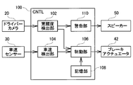
- FIG. 2 shows a rough internal configuration of the control device 100.
- the control device 100 includes a wakefulness detection unit 102, a vehicle speed detection unit 104, a braking unit 106, a storage unit 108, and a warning unit 110.
- each “unit” can be realized as software as a part of a computer program, or can be realized as hardware using an IC chip or a large-scale integrated circuit.
- the arousal level detection unit 102 detects the driver's arousal level by analyzing the face image, and the detected arousal level is applied to the braking unit 106. And output to the warning unit 110.
- the vehicle speed detection unit 104 acquires the vehicle speed from the vehicle speed sensor 30 at a constant cycle, and outputs the acquired vehicle speed toward the braking unit 106.
- the braking unit 106 controls the braking of the vehicle 1 by operating the brake actuator 42 based on the awakening level received from the awakening level detection unit 102 and the vehicle speed received from the vehicle speed detection unit 104.
- the storage unit 108 stores in advance data related to a pattern for braking the vehicle 1 (corresponding to a braking mode), and the braking unit 106 reads out the pattern data stored in the storage unit 108 and stores it in the vehicle 1.
- the brake is to be applied.
- the warning unit 110 receives the wakefulness level detected by the wakefulness level detection unit 102, the warning unit 110 determines whether or not a warning sound needs to be output and outputs a warning sound from the speaker 50.
- corresponds to the arousal level detection part (or means) in this invention.
- the vehicle speed detection unit 104 of the present embodiment corresponds to the travel speed detection unit (or means) in the present disclosure.
- the storage unit 108 of this embodiment corresponds to the storage unit (or means) in the present disclosure.
- the braking unit 106 of the present embodiment corresponds to the braking unit (or means) in the present disclosure.
- the control device 100 according to the present embodiment corresponds to the vehicle braking device according to the present disclosure.
- the driver camera 20 of the present embodiment corresponds to the photographing unit (or means) in the present disclosure. Note that the photographing unit may be included in the vehicle braking device, or may be configured as a separate body.
- FIG. 3 shows a flowchart of the vehicle braking process of this embodiment.
- This process is performed by the control device 100 of the vehicle braking system 10.
- the control device 100 first acquires a face image taken by the driver camera 20 (S100).
- the control apparatus 100 detects a driver
- Various known methods can be used to detect the arousal level. For example, the opening degree of the eye, the blink frequency, and the movement of the line of sight are detected from the driver's face image, and the control device 100 can detect the driver's arousal level based on such information.
- the awakening level decreases as the driver feels sleepy or distracts, and the awakening level increases as the driver's consciousness becomes clearer.
- the control device 100 determines whether or not the detected arousal level is equal to or less than the first threshold (S104). When the driver's consciousness is clear, the wakefulness does not fall below the first threshold value, so the control device 100 determines “no” in S104, the process returns to the top, and the control device 100 A face image is acquired from the driver camera 20 (S100).
- the control device 100 determines whether the awakening level is equal to or lower than the second threshold (S106).
- the second threshold value is set to a value smaller than the first threshold value.
- the control device 100 determines that the driver's arousal level has decreased, but is not high enough to brake the vehicle 1.
- One warning sound is output from the speaker 50 (S108).
- the first warning sound is stored in advance in a memory (not shown) of the control device 100. By outputting the warning sound from the speaker 50 in this manner, it is possible to avoid a decrease in the driver's arousal level and continue driving safely. Then, after outputting the warning sound, the process returns to the top, and the control device 100 again acquires a face image from the driver camera 20 (S100), and repeats the series of processes described above.
- the control device 100 determines that the driver's arousal level is equal to or lower than the second threshold (S106: yes)
- the control device 100 outputs the second warning sound from the speaker 50 (S110).
- the second warning sound is output at a louder volume than the first warning sound so that even a driver whose awakening level has decreased can be recognized.
- the content of the warning of the second warning sound is also a content that strongly warns the driver of the danger.
- the second warning sound may be a sound for notifying that the vehicle 1 is braked.
- the second warning sound is also stored in advance in a memory (not shown) of the control device 100.
- the control device 100 determines whether or not the vehicle speed acquired from the vehicle speed sensor 30 is smaller than the stoppable speed (S112).
- the stoppable speed is a travel speed at which the vehicle 1 can be safely stopped. If the vehicle is stopped by applying abrupt braking in a state where the vehicle speed is high, not only a large impact is applied to the occupant of the vehicle 1 including the driver, but also a rear-end collision may occur.
- the stoppable speed is set as a vehicle speed at which the vehicle 1 can be safely stopped without causing such a problem, and is typically set at 20 km / h. As a result, when the control device 100 determines that the vehicle speed is higher than the stoppable speed (S112: no), a deceleration process described below is started (S200).
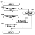
- FIG. 4 shows a flowchart of the deceleration process performed in the vehicle braking process.
- the control device 100 determines whether or not the vehicle speed is equal to or higher than the first threshold speed (S202).
- the first threshold speed is a speed that becomes a threshold for determining whether or not the vehicle 1 is traveling at a relatively high speed, and is typically set to 60 km / h.
- the control device 100 determines that the vehicle 1 is traveling at a high speed, and performs a first pattern braking operation described later. (S204).
- the control device 100 determines whether or not the vehicle speed is equal to or higher than the second threshold speed (S206).
- the second threshold speed is a speed that is a threshold for determining whether or not the vehicle 1 is traveling at a standard speed, and is typically set to 40 kilometers per hour.
- the control device 100 determines that the vehicle 1 is traveling at a standard speed, The control device 100 performs the second pattern braking operation (S208).
- the control device 100 determines that the vehicle 1 is traveling at a relatively low speed although it is higher than the stoppable speed.
- the control device 100 performs the third pattern braking operation (S210).
- FIG. 5 illustrates various patterns for decelerating the vehicle 1.
- the brake actuator 42 is operated to depress the brake pedal 40 for a time T1, and then a braking operation is performed to hold the depressed state for a time t1.
- the amount of depression does not change while the brake pedal 40 is depressed.
- the operation of holding the state where the depression is released for the time t1 is performed once. This operation may be repeated a plurality of times (for example, three times).
- the time during which the brake pedal 40 is depressed is shortened from the time T1 to the time T2 as compared with the first pattern.
- the time for releasing the depression is extended from time t1 to time t2.
- the time during which the brake pedal 40 is depressed is shortened from time T2 to time T3 as compared to the second pattern.
- the time for releasing the depression is extended from time t2 to time t3.
- the time required for one braking operation is set to be the same in any pattern, and accordingly, the total time of time T1 and time t1, the total time of time T2 and time t2, The total time of time T1 and time t1 is the same.
- the depression amount of the brake pedal 40 is the same.
- the deceleration process shown in FIG. 4 after the control device 100 performs a braking operation of any pattern according to the vehicle speed of the vehicle 1 (S204, S206, S210), the deceleration process is terminated and the vehicle of FIG. Return to the braking process. Then, after returning from the deceleration process, the process returns to the beginning of the vehicle braking process, and the control device 100 acquires a face image from the driver camera 20 again (S100), and starts the series of processes described above.
- the control device 100 When the vehicle speed of the vehicle 1 is reduced to a stoppable speed by repeating such processing (S112: yes), the control device 100 operates the brake actuator 42 while turning on the hazard lamp (not shown) to turn on the brake pedal 40. The vehicle 1 is stopped by stepping on (S114), and the vehicle braking process of FIG. 3 is terminated. Further, while the vehicle speed of the vehicle 1 is decelerated to the stoppable speed, the control device 100 detects the driver's arousal level and compares the arousal level with the first threshold value and the second threshold value (S100, S102, S104, S106). Therefore, when the driver wakes up while the vehicle 1 is decelerating, the deceleration process is stopped.
- S100, S102, S104, S106 the first threshold value and the second threshold value
- the control device 100 performs the deceleration shown in FIG. The vehicle is stopped after the vehicle 1 is decelerated by performing the process. In the deceleration process, the vehicle 1 is decelerated with a pattern corresponding to the vehicle speed. For this reason, the vehicle 1 can be safely stopped after decelerating the vehicle 1 safely without being collided with the following vehicle.
- this point will be described in detail.
- the time for which the brake pedal 40 is depressed is shortened as the vehicle speed of the vehicle 1 decreases, and accordingly, the degree of braking of the vehicle 1 is set to be small. This is because if the vehicle is braked when the vehicle speed is low, the vehicle 1 is decelerated suddenly, and there is a possibility that the vehicle 1 may collide with the following vehicle. However, when the vehicle 1 is traveling at a relatively high speed, the vehicle 1 does not decelerate suddenly even if a large amount of braking is applied (unless extremely large braking is applied). Rather, if the vehicle is not braked to a certain extent, the vehicle 1 may take too long to decelerate.
- the vehicle braking system 10 is set so that as the vehicle speed of the vehicle 1 increases, the time that the brake pedal 40 is depressed is lengthened and large braking can be applied. As a result, it is possible to quickly decelerate the vehicle 1 to the stoppable speed, and it is possible to safely stop the vehicle 1 without causing the possibility of a rear-end collision with the following vehicle.
- the degree of arousal from the face image (corresponding to S102 in FIG. 3)
- the driver's eyes are closed continuously for a certain period of time (for example, 2 to 3 seconds)
- a certain period of time for example, 2 to 3 seconds
- the small arousal level equal to or less than the second threshold may be immediately used. In this way, even if the driver suddenly feels strong sleepiness while driving the vehicle 1, the vehicle 1 can be immediately decelerated and stopped safely.
- the brake actuator 42 is operated to change the time for which the brake pedal 40 is depressed, thereby changing the degree of braking of the vehicle 1.
- the degree of braking can be varied, it is not necessarily limited to changing the depression time of the brake pedal 40.
- the degree of braking may be varied by changing the amount of depression of the brake pedal 40.
- FIG. 6 illustrates a case where the degree of braking is varied by changing the depression amount of the brake pedal 40.
- the brake pedal 40 is depressed with the depression amount P1 for the time T0, and then the braking operation is performed to maintain the depression released state for the time t0.
- the time T0 when the brake pedal 40 is depressed and the time t0 when the depression is released are the same as those in the first pattern, but the depression amount decreases to P2 in the second pattern. However, in the third pattern, it decreases to P3.
- the present invention is not limited to the patterns illustrated in FIGS. 5 and 6, and the degree of braking may be varied by changing the depression time and depression amount of the brake pedal 40. (Modification)
- the braking operation has been described as being performed exclusively for safely decelerating the vehicle 1.
- the braking operation of the vehicle 1 may be used to awaken the driver in addition to the deceleration of the vehicle 1.
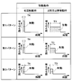
- FIG. 7 illustrates a braking operation used in a vehicle braking system 10 according to a modified example.
- two types of braking operations are set, that is, a braking operation at the first braking and a braking operation at the second and subsequent braking.
- the second and subsequent braking operations are the same as the braking operation of the present embodiment described above with reference to FIG. That is, the amount of depression of the brake pedal 40 is constant, and the degree of braking is changed by varying the depression time.
- the braking operation is performed by depressing the brake pedal 40 momentarily for a short time. That is, in any of the first pattern, the second pattern, and the third pattern, the depression time of the brake pedal 40 is set to a short time T4, and the depression amount is set for the second and subsequent braking. It is set to a larger depression amount. Furthermore, when the amount of depression at the time of initial braking of each pattern is compared, the amount of depression of the first pattern is the largest, and a smaller amount of depression is set as the second pattern and the third pattern are reached.
- FIG. 8A and FIG. 8B illustrate how the vehicle 1 is decelerated by the vehicle braking system 10 according to the modified example.
- FIG. 8A shows a case where the braking operation is started from the first pattern because the vehicle speed at the start of braking is larger than the first threshold speed.
- FIG. 8B shows a case where the braking operation is started from the second pattern because the vehicle speed at the start of braking is smaller than the first threshold speed but larger than the second threshold speed.
- the first brake operation is instantaneous and stronger than the second and subsequent brake operations.
- a stronger braking operation is instantaneously performed, so that the vehicle 1 moves differently from the moment. This movement acts to surprise the driver and restore the reduced alertness. As a result, if the driver's arousal level recovers to a normal level, the vehicle 1 can continue to travel.
- the vehicle braking device When the vehicle braking apparatus according to an example of the present disclosure detects that the driver's arousal level has dropped below a threshold value, the vehicle braking device reads the braking mode stored according to the traveling speed of the vehicle and brakes the traveling of the vehicle. Call.
- the braking mode stored in advance is a mode in which the degree of braking is smaller as the traveling speed of the vehicle is lower.
- a braking mode is stored in advance so that the degree of braking decreases as the traveling speed of the vehicle decreases. And when a driver
- the vehicle travels by braking the vehicle for a predetermined braking time corresponding to the traveling speed and then releasing the braking. It is good also to apply. And as a braking mode, it is good also as memorize
- the degree of braking can be changed by changing the braking strength instead of the braking time. However, if the degree of braking is changed by the braking time, it is irrelevant even if the degree of braking is increased. There is no need to apply braking. Therefore, it is possible to safely brake the running of the vehicle without giving an impact to the vehicle.
- the degree of arousal is detected by capturing an image of the driver's face (face image) and extracting the driver's eyes from the face image. Also good. When the extracted driver's eyes are closed, the degree of arousal may be determined to be equal to or less than the threshold value, and braking of the vehicle may be applied.
Landscapes
- Engineering & Computer Science (AREA)
- Transportation (AREA)
- Mechanical Engineering (AREA)
- Health & Medical Sciences (AREA)
- Life Sciences & Earth Sciences (AREA)
- Chemical & Material Sciences (AREA)
- Combustion & Propulsion (AREA)
- Physics & Mathematics (AREA)
- Social Psychology (AREA)
- Heart & Thoracic Surgery (AREA)
- Educational Technology (AREA)
- Hospice & Palliative Care (AREA)
- Psychiatry (AREA)
- Psychology (AREA)
- Child & Adolescent Psychology (AREA)
- General Physics & Mathematics (AREA)
- Biophysics (AREA)
- Pathology (AREA)
- Biomedical Technology (AREA)
- Developmental Disabilities (AREA)
- Medical Informatics (AREA)
- Molecular Biology (AREA)
- Surgery (AREA)
- Animal Behavior & Ethology (AREA)
- General Health & Medical Sciences (AREA)
- Public Health (AREA)
- Veterinary Medicine (AREA)
- Regulating Braking Force (AREA)
- Measurement Of The Respiration, Hearing Ability, Form, And Blood Characteristics Of Living Organisms (AREA)
- Traffic Control Systems (AREA)
Abstract
Provided is a vehicle braking device that brakes the travel of a vehicle (1) upon detection of a decrease in the level of wakefulness of a driver as the vehicle (1) travels. The vehicle braking device is provided with: a level of wakefulness detection unit (102) that detects the level of wakefulness of the driver; a travel speed detection unit (104) that detects a travel speed of the vehicle (1); a storage unit (108) storing a brake mode of the vehicle (1) in association with the travel speed; and a braking unit (106) that brakes the travel of the vehicle (1) when the level of wakefulness is equal to or less than a predetermined threshold value, in the brake mode corresponding to the travel speed. The storage unit (108) stores the brake mode of smaller braking degree as the travel speed decreases.
Description
本出願は、2013年5月14日に出願された日本国特許出願2013-102084号に基づくものであり、ここにその記載内容を参照により援用する。
This application is based on Japanese Patent Application No. 2013-102084 filed on May 14, 2013, the contents of which are incorporated herein by reference.
本開示は、車両の走行中に運転者の覚醒度が低下したことを検出して、車両の走行に制動をかける車両制動装置に関する。
The present disclosure relates to a vehicle braking device that detects that the driver's arousal level has decreased during traveling of the vehicle and applies braking to the traveling of the vehicle.
車両の運転者に対する運転支援の一環として、運転者が眠気を感じていることや、集中力が低下していることなどを検出して運転者に警告することで、車両の安全な走行を確保しようとする技術が開発されている。また、警告によっても運転者が覚醒せず、居眠り運転をしている場合には、車両の走行に制動をかけることによって衝突事故の発生を回避しようとする技術が提案されている(特許文献1、特許文献2)。
As part of driving assistance for the driver of the vehicle, a safe driving of the vehicle is ensured by detecting that the driver feels drowsy or that the concentration is low and alerting the driver. The technology to be developed has been developed. In addition, when the driver does not wake up due to a warning and is driving a nap, a technique has been proposed that attempts to avoid the occurrence of a collision accident by braking the running of the vehicle (Patent Document 1). Patent Document 2).
本願発明者は車両制動装置について以下を見出した。提案されている技術では、車両の走行に制動をかけることによって自車が衝突する危険は低減できるものの、他車から追突される危険が増加する虞がある。
The inventor of the present application has found the following regarding the vehicle braking device. With the proposed technology, although the risk of collision of the own vehicle can be reduced by braking the running of the vehicle, there is a risk that the risk of being collided from another vehicle will increase.
本開示は、上述した問題に鑑みてなされたものであり、運転者の覚醒度が低下したことを検出した場合に、他車から追突されることなく安全に、車両の走行に制動をかけることが可能な車両制動装置の提供を目的とする。
The present disclosure has been made in view of the above-described problems, and when it is detected that the driver's arousal level has decreased, the vehicle can be safely braked without being collided from another vehicle. It is an object of the present invention to provide a vehicle braking device capable of performing
本開示の一例によれば、車両の走行中に運転者の覚醒度が低下したことを検出して、該車両の走行に制動をかける車両制動装置が提供される。車両制動装置は、前記運転者の覚醒度を検出する覚醒度検出部と、前記車両の走行速度を検出する走行速度検出部と、前記車両の制動態様を前記走行速度に対応付けて記憶している記憶部と、前記覚醒度が所定の閾値以下の場合には、前記走行速度に応じた前記制動態様で前記車両の走行に制動をかける制動部と、を備える。前記記憶部は、前記走行速度が低くなるほど、制動の程度が小さい前記制動態様を記憶する。
According to an example of the present disclosure, there is provided a vehicle braking device that detects that the driver's arousal level has decreased during traveling of the vehicle and brakes the traveling of the vehicle. The vehicle braking device stores a wakefulness detection unit that detects the driver's wakefulness, a travel speed detection unit that detects the travel speed of the vehicle, and stores the braking mode of the vehicle in association with the travel speed. And a braking unit that applies braking to the traveling of the vehicle in the braking mode according to the traveling speed when the arousal level is equal to or less than a predetermined threshold. The storage unit stores the braking mode in which the degree of braking is smaller as the traveling speed is lower.
このような車両制動装置によれば、運転者の覚醒度が低下したことを検出した場合に、他車から追突されることなく安全に、車両の走行に制動をかけることが可能になる。
According to such a vehicle braking device, when it is detected that the driver's arousal level has decreased, it is possible to safely brake the running of the vehicle without being collided from another vehicle.
本開示についての上記および他の目的、特徴や利点は、添付の図面を参照した下記の詳細な説明から、より明確になる。添付図面において
図1は、車両制動システムを搭載した車両の全体構成を示す説明図であり、
図2は、制御装置の構造概略を示すブロック図であり、
図3は、車両制動処理のフローチャートであり、
図4は、車両制動処理中で実行される減速処理のフローチャートであり、
図5は、車両を減速する各種パターンについての説明図であり、
図6は、車両を減速する各種パターンの他の態様についての説明図であり、
図7は、変形例で車両を減速する各種パターンについての説明図であり、
図8Aは、変形例で車両を減速する様子を例示した説明図であり、
図8Bは、変形例で車両を減速する様子を例示した説明図である。
The above and other objects, features and advantages of the present disclosure will become more apparent from the following detailed description with reference to the accompanying drawings. In the attached drawings
FIG. 1 is an explanatory diagram showing the overall configuration of a vehicle equipped with a vehicle braking system, FIG. 2 is a block diagram showing a schematic structure of the control device, FIG. 3 is a flowchart of the vehicle braking process. FIG. 4 is a flowchart of the deceleration process executed during the vehicle braking process. FIG. 5 is an explanatory diagram of various patterns for decelerating the vehicle. FIG. 6 is an explanatory diagram of other aspects of various patterns for decelerating the vehicle. FIG. 7 is an explanatory diagram of various patterns for decelerating the vehicle in a modified example. FIG. 8A is an explanatory view illustrating the manner in which the vehicle is decelerated in a modified example. FIG. 8B is an explanatory diagram illustrating the manner in which the vehicle is decelerated in a modified example.
以下では、上述した本開示の内容を明確にするために実施例について説明する。
(装置構成)
図1には、車両制動システム10を搭載した車両1の大まかな構成が示されている。図示されるように本実施例の車両制動システム10は、車両1の運転者の顔面の画像(顔画像)を一定周期で撮影するドライバーカメラ20と、車両1の走行速度(車速)を出力する車速センサー30と、ブレーキペダル40を動かすブレーキアクチュエータ42と、ブレーキアクチュエータ42を制御して車両1に制動をかける制御装置100とを備えている。制御装置100は、CPUやメモリーやタイマーなどがバスによって接続された周知のマイクロコンピューターである。また、車両1には、運転者に警告音を出力するスピーカー50も搭載されており、制御装置100はスピーカー50にも接続されている。 Hereinafter, examples will be described in order to clarify the contents of the present disclosure described above.
(Device configuration)
FIG. 1 shows a rough configuration of avehicle 1 equipped with a vehicle braking system 10. As shown in the figure, the vehicle braking system 10 according to the present embodiment outputs a driver camera 20 that captures images (face images) of the face of the driver of the vehicle 1 at a certain period, and a traveling speed (vehicle speed) of the vehicle 1. A vehicle speed sensor 30, a brake actuator 42 that moves the brake pedal 40, and a control device 100 that controls the brake actuator 42 to brake the vehicle 1 are provided. The control device 100 is a known microcomputer in which a CPU, a memory, a timer, and the like are connected by a bus. The vehicle 1 is also equipped with a speaker 50 that outputs a warning sound to the driver, and the control device 100 is also connected to the speaker 50.
(装置構成)
図1には、車両制動システム10を搭載した車両1の大まかな構成が示されている。図示されるように本実施例の車両制動システム10は、車両1の運転者の顔面の画像(顔画像)を一定周期で撮影するドライバーカメラ20と、車両1の走行速度(車速)を出力する車速センサー30と、ブレーキペダル40を動かすブレーキアクチュエータ42と、ブレーキアクチュエータ42を制御して車両1に制動をかける制御装置100とを備えている。制御装置100は、CPUやメモリーやタイマーなどがバスによって接続された周知のマイクロコンピューターである。また、車両1には、運転者に警告音を出力するスピーカー50も搭載されており、制御装置100はスピーカー50にも接続されている。 Hereinafter, examples will be described in order to clarify the contents of the present disclosure described above.
(Device configuration)
FIG. 1 shows a rough configuration of a
図2には、制御装置100の大まかな内部構成が示されている。図示されるように、制御装置100には、覚醒度検出部102と、車速検出部104と、制動部106と、記憶部108と、警告部110とが設けられている。
FIG. 2 shows a rough internal configuration of the control device 100. As shown in the figure, the control device 100 includes a wakefulness detection unit 102, a vehicle speed detection unit 104, a braking unit 106, a storage unit 108, and a warning unit 110.
尚、これらの「部」は、制御装置100が有する機能に着目して制御装置100の内部を便宜的に分類したものであり、制御装置100の内部が、それぞれの「部」に対応する部分に物理的に区分されていることを意味するものではない。従って、それぞれの「部」は、コンピュータープログラムの一部分としてソフトウェア的に実現することもできるし、ICチップや大規模集積回路によってハードウェア的に実現することもできる。
These “parts” are classified for convenience in the inside of the control apparatus 100 by paying attention to the function of the control apparatus 100, and the inside of the control apparatus 100 corresponds to each “part”. It does not mean that they are physically separated. Accordingly, each “unit” can be realized as software as a part of a computer program, or can be realized as hardware using an IC chip or a large-scale integrated circuit.
覚醒度検出部102は、ドライバーカメラ20が一定周期で取得した運転者の顔画像を受け取ると、顔画像を解析することによって運転者の覚醒度を検出して、検出した覚醒度を制動部106および警告部110に出力する。車速検出部104は、車速センサー30から一定周期で車速を取得して、取得した車速を制動部106に向かって出力する。制動部106は、覚醒度検出部102から受け取った覚醒度と、車速検出部104から受け取った車速とに基づいてブレーキアクチュエータ42を動作させることにより、車両1に制動をかける動作を司る。記憶部108には、車両1に制動をかけるパターンに関するデータ(制動態様に相当する)が予め記憶されており、制動部106は記憶部108に記憶されているパターンのデータを読み出して車両1に制動をかけるようになっている。警告部110は、覚醒度検出部102で検出された覚醒度を受け取ると、警告音の出力要否を判断してスピーカー50から警告音を出力する。
When the driver camera 20 receives the driver's face image acquired by the driver camera 20 at a constant cycle, the arousal level detection unit 102 detects the driver's arousal level by analyzing the face image, and the detected arousal level is applied to the braking unit 106. And output to the warning unit 110. The vehicle speed detection unit 104 acquires the vehicle speed from the vehicle speed sensor 30 at a constant cycle, and outputs the acquired vehicle speed toward the braking unit 106. The braking unit 106 controls the braking of the vehicle 1 by operating the brake actuator 42 based on the awakening level received from the awakening level detection unit 102 and the vehicle speed received from the vehicle speed detection unit 104. The storage unit 108 stores in advance data related to a pattern for braking the vehicle 1 (corresponding to a braking mode), and the braking unit 106 reads out the pattern data stored in the storage unit 108 and stores it in the vehicle 1. The brake is to be applied. When the warning unit 110 receives the wakefulness level detected by the wakefulness level detection unit 102, the warning unit 110 determines whether or not a warning sound needs to be output and outputs a warning sound from the speaker 50.
尚、本実施例の覚醒度検出部102は、本発明における覚醒度検出部(または手段)に対応する。本実施例の車速検出部104は、本開示における走行速度検出部(または手段)に対応する。本実施例の記憶部108は、本開示における記憶部(または手段)に対応する。本実施例の制動部106は、本開示における制動部(または手段)に対応する。本実施例の制御装置100は、本開示における車両制動装置に対応する。本実施例のドライバーカメラ20は、本開示における撮影部(または手段)に対応する。なお、撮影部は車両制動装置に含まれていても良いし、別体として構成されていてもよい。
(車両制動処理)
図3には、本実施例の車両制動処理のフローチャートが示されている。この処理は、車両制動システム10の制御装置100によって行われる。車両制動処理では、制御装置100は、先ず始めに、ドライバーカメラ20で撮影した顔画像を取得する(S100)。そして、制御装置100は、取得した顔画像を解析することによって、運転者の覚醒度を検出する(S102)。覚醒度の検出には、周知の種々の方法を用いることができる。たとえば、運転者の顔画像から眼の開度や、瞬きの頻度、視線の動きを検出して、それらの情報に基づいて制御装置100は運転者の覚醒度を検出することができる。尚、本実施例では、運転者が眠気を感じたり、注意が散漫になったりするほど覚醒度が低くなり、運転者の意識がはっきりしているほど覚醒度が高くなるものとする。 In addition, the arousallevel detection part 102 of a present Example respond | corresponds to the arousal level detection part (or means) in this invention. The vehicle speed detection unit 104 of the present embodiment corresponds to the travel speed detection unit (or means) in the present disclosure. The storage unit 108 of this embodiment corresponds to the storage unit (or means) in the present disclosure. The braking unit 106 of the present embodiment corresponds to the braking unit (or means) in the present disclosure. The control device 100 according to the present embodiment corresponds to the vehicle braking device according to the present disclosure. The driver camera 20 of the present embodiment corresponds to the photographing unit (or means) in the present disclosure. Note that the photographing unit may be included in the vehicle braking device, or may be configured as a separate body.
(Vehicle braking process)
FIG. 3 shows a flowchart of the vehicle braking process of this embodiment. This process is performed by thecontrol device 100 of the vehicle braking system 10. In the vehicle braking process, the control device 100 first acquires a face image taken by the driver camera 20 (S100). And the control apparatus 100 detects a driver | operator's arousal level by analyzing the acquired face image (S102). Various known methods can be used to detect the arousal level. For example, the opening degree of the eye, the blink frequency, and the movement of the line of sight are detected from the driver's face image, and the control device 100 can detect the driver's arousal level based on such information. In this embodiment, it is assumed that the awakening level decreases as the driver feels sleepy or distracts, and the awakening level increases as the driver's consciousness becomes clearer.
(車両制動処理)
図3には、本実施例の車両制動処理のフローチャートが示されている。この処理は、車両制動システム10の制御装置100によって行われる。車両制動処理では、制御装置100は、先ず始めに、ドライバーカメラ20で撮影した顔画像を取得する(S100)。そして、制御装置100は、取得した顔画像を解析することによって、運転者の覚醒度を検出する(S102)。覚醒度の検出には、周知の種々の方法を用いることができる。たとえば、運転者の顔画像から眼の開度や、瞬きの頻度、視線の動きを検出して、それらの情報に基づいて制御装置100は運転者の覚醒度を検出することができる。尚、本実施例では、運転者が眠気を感じたり、注意が散漫になったりするほど覚醒度が低くなり、運転者の意識がはっきりしているほど覚醒度が高くなるものとする。 In addition, the arousal
(Vehicle braking process)
FIG. 3 shows a flowchart of the vehicle braking process of this embodiment. This process is performed by the
続いて、制御装置100は、検出した覚醒度が第1閾値以下か否かを判断する(S104)。運転者の意識がはっきりしている場合は、覚醒度が第1閾値を下回ることはないので、制御装置100は、S104では「no」と判断し、処理は先頭に戻って、制御装置100はドライバーカメラ20から顔画像を取得する(S100)。
Subsequently, the control device 100 determines whether or not the detected arousal level is equal to or less than the first threshold (S104). When the driver's consciousness is clear, the wakefulness does not fall below the first threshold value, so the control device 100 determines “no” in S104, the process returns to the top, and the control device 100 A face image is acquired from the driver camera 20 (S100).
これに対して、覚醒度が第1閾値以下であった場合は(S104:yes)、制御装置100は覚醒度が第2閾値以下であるか否かを判断する(S106)。ここで、第2閾値は第1閾値よりも小さな値に設定されている。覚醒度が第2閾値よりも大きかった場合は(S106:no)、制御装置100は、運転者の覚醒度は低下しているものの、車両1に制動をかけるほどではないと判断して、第1警告音をスピーカー50から出力する(S108)。第1警告音は、制御装置100の図示しないメモリーに予め記憶されている。こうしてスピーカー50から警告音を出力することで、運転者の覚醒度が低下することを回避して、安全に運転を継続させることができる。そして、警告音を出力した後は、処理は先頭に戻り、そして、再び制御装置100はドライバーカメラ20から顔画像を取得し(S100)、上述した一連の処理を繰り返す。
On the other hand, when the arousal level is equal to or lower than the first threshold (S104: yes), the control device 100 determines whether the awakening level is equal to or lower than the second threshold (S106). Here, the second threshold value is set to a value smaller than the first threshold value. When the arousal level is greater than the second threshold (S106: no), the control device 100 determines that the driver's arousal level has decreased, but is not high enough to brake the vehicle 1. One warning sound is output from the speaker 50 (S108). The first warning sound is stored in advance in a memory (not shown) of the control device 100. By outputting the warning sound from the speaker 50 in this manner, it is possible to avoid a decrease in the driver's arousal level and continue driving safely. Then, after outputting the warning sound, the process returns to the top, and the control device 100 again acquires a face image from the driver camera 20 (S100), and repeats the series of processes described above.
以上は、運転者の覚醒度が低下しているが、第2閾値までは低下していなかった場合について説明した。これに対して、制御装置100が、運転者の覚醒度が第2閾値以下であると判断した場合は(S106:yes)、制御装置100はスピーカー50から第2警告音を出力する(S110)。この第2警告音は、覚醒度が低下した運転者であっても認識することができるように、第1警告音よりも大きな音量で出力される。第2警告音の警告の内容も、運転者に危険を強く警告する内容となっている。第2警告音は、車両1に制動をかける旨を予告する音声としてもよい。尚、第2警告音も、制御装置100の図示しないメモリーに予め記憶されている。
The above describes the case where the driver's arousal level has decreased, but has not decreased to the second threshold. On the other hand, when the control device 100 determines that the driver's arousal level is equal to or lower than the second threshold (S106: yes), the control device 100 outputs the second warning sound from the speaker 50 (S110). . The second warning sound is output at a louder volume than the first warning sound so that even a driver whose awakening level has decreased can be recognized. The content of the warning of the second warning sound is also a content that strongly warns the driver of the danger. The second warning sound may be a sound for notifying that the vehicle 1 is braked. The second warning sound is also stored in advance in a memory (not shown) of the control device 100.
そして、制御装置100は、車速センサー30から取得した車速が停車可能速度より小さいか否かを判断する(S112)。停車可能速度とは、車両1を安全に停車させることが可能な走行速度である。車速が高い状態において急激に制動をかけて車両を停車させると、運転者を含む車両1の乗員に大きな衝撃がかかるだけでなく、後続する車両に追突される虞が生じる。停車可能速度とは、こうした問題を生じさせずに車両1を安全に停車させることが可能な車速として設定されているものであり、代表的には時速20キロメートルに設定されている。その結果、車速が停車可能速度よりも大きいと制御装置100が判断した場合は(S112:no)、以下に説明する減速処理を開始する(S200)。
Then, the control device 100 determines whether or not the vehicle speed acquired from the vehicle speed sensor 30 is smaller than the stoppable speed (S112). The stoppable speed is a travel speed at which the vehicle 1 can be safely stopped. If the vehicle is stopped by applying abrupt braking in a state where the vehicle speed is high, not only a large impact is applied to the occupant of the vehicle 1 including the driver, but also a rear-end collision may occur. The stoppable speed is set as a vehicle speed at which the vehicle 1 can be safely stopped without causing such a problem, and is typically set at 20 km / h. As a result, when the control device 100 determines that the vehicle speed is higher than the stoppable speed (S112: no), a deceleration process described below is started (S200).
図4には、車両制動処理の中で行われる減速処理のフローチャートが示されている。減速処理では、先ず始めに、車速が第1閾値速度以上か否かを制御装置100が判断する(S202)。第1閾値速度とは、車両1が比較的高い速度での走行中であるか否かを判断するための閾値となる速度であり、代表的には時速60キロメートルに設定されている。その結果、車速が第1閾値速度以上であった場合は(S202:yes)、車両1が高い速度で走行中であると制御装置100が判断して、後述する第1パターンの制動動作を実施する(S204)。
FIG. 4 shows a flowchart of the deceleration process performed in the vehicle braking process. In the deceleration process, first, the control device 100 determines whether or not the vehicle speed is equal to or higher than the first threshold speed (S202). The first threshold speed is a speed that becomes a threshold for determining whether or not the vehicle 1 is traveling at a relatively high speed, and is typically set to 60 km / h. As a result, when the vehicle speed is equal to or higher than the first threshold speed (S202: yes), the control device 100 determines that the vehicle 1 is traveling at a high speed, and performs a first pattern braking operation described later. (S204).
これに対して、車速が第1閾値速度よりも小さかった場合は(S202:no)、車速が第2閾値速度以上か否かを制御装置100が判断する(S206)。第2閾値速度とは、車両1が標準的な速度での走行中であるか否かを判断するための閾値となる速度であり、代表的には時速40キロメートルに設定されている。その結果、車速が第1閾値速度よりは小さいが第2閾値速度以上であった場合は(S206:yes)、車両1が標準的な速度で走行中であると制御装置100が判断して、制御装置100は、第2パターンの制動動作を実施する(S208)。これに対して、車速が第2閾値速度よりも小さかった場合は(S206:no)、停車可能速度よりは高いものの車両1が比較的低速で走行しているものと制御装置100が判断して、制御装置100が第3パターンの制動動作を実施する(S210)。
On the other hand, when the vehicle speed is smaller than the first threshold speed (S202: no), the control device 100 determines whether or not the vehicle speed is equal to or higher than the second threshold speed (S206). The second threshold speed is a speed that is a threshold for determining whether or not the vehicle 1 is traveling at a standard speed, and is typically set to 40 kilometers per hour. As a result, if the vehicle speed is smaller than the first threshold speed but greater than or equal to the second threshold speed (S206: yes), the control device 100 determines that the vehicle 1 is traveling at a standard speed, The control device 100 performs the second pattern braking operation (S208). On the other hand, when the vehicle speed is lower than the second threshold speed (S206: no), the control device 100 determines that the vehicle 1 is traveling at a relatively low speed although it is higher than the stoppable speed. The control device 100 performs the third pattern braking operation (S210).
図5には、車両1を減速させるための各種パターンが例示されている。第1パターンでは、ブレーキアクチュエータ42を操作してブレーキペダル40を時間T1に亘って踏み込んだ後、踏み込みを解除した状態を時間t1に亘って保持する制動動作を行う。尚、ここでは、ブレーキペダル40を踏み込んでいる間、踏み込み量は変わらないものとしている。また、本実施例の制動動作では、ブレーキペダル40を時間T1に亘って踏み込んだ後、踏み込みを解除した状態を時間t1の間、保持する動作を1回行うものとするが、1回の制動動作でこの動作を複数回(例えば3回)繰り返すようにしても良い。
FIG. 5 illustrates various patterns for decelerating the vehicle 1. In the first pattern, the brake actuator 42 is operated to depress the brake pedal 40 for a time T1, and then a braking operation is performed to hold the depressed state for a time t1. Here, it is assumed that the amount of depression does not change while the brake pedal 40 is depressed. In the braking operation of this embodiment, after the brake pedal 40 is depressed for the time T1, the operation of holding the state where the depression is released for the time t1 is performed once. This operation may be repeated a plurality of times (for example, three times).
これに対して第2パターンでは、第1パターンに比較してブレーキペダル40を踏み込んでいる時間が時間T1から時間T2に短縮されている。そして、踏み込みを解除している時間が時間t1から時間t2に延長されている。更に、第3パターンでは、第2パターンに比較してブレーキペダル40を踏み込んでいる時間が時間T2から時間T3に短縮されている。そして、踏み込みを解除している時間が時間t2から時間t3に延長されている。尚、本実施例では、何れのパターンにおいても1回の制動動作に要する時間は同じに設定されており、従って、時間T1と時間t1との合計時間、時間T2と時間t2との合計時間、時間T1と時間t1との合計時間は何れも同じとなる。また、何れのパターンにおいてもブレーキペダル40の踏み込み量は同じものとしている。
In contrast, in the second pattern, the time during which the brake pedal 40 is depressed is shortened from the time T1 to the time T2 as compared with the first pattern. The time for releasing the depression is extended from time t1 to time t2. Further, in the third pattern, the time during which the brake pedal 40 is depressed is shortened from time T2 to time T3 as compared to the second pattern. Then, the time for releasing the depression is extended from time t2 to time t3. In this embodiment, the time required for one braking operation is set to be the same in any pattern, and accordingly, the total time of time T1 and time t1, the total time of time T2 and time t2, The total time of time T1 and time t1 is the same. In any pattern, the depression amount of the brake pedal 40 is the same.
図4に示した減速処理では、制御装置100が、車両1の車速に応じて何れかのパターンの制動動作を行った後(S204、S206、S210)、減速処理を終了して図3の車両制動処理に復帰する。そして、減速処理から復帰した後は、処理は車両制動処理の先頭に戻り、制御装置100は再びドライバーカメラ20から顔画像を取得し(S100)、上述した一連の処理を開始する。
In the deceleration process shown in FIG. 4, after the control device 100 performs a braking operation of any pattern according to the vehicle speed of the vehicle 1 (S204, S206, S210), the deceleration process is terminated and the vehicle of FIG. Return to the braking process. Then, after returning from the deceleration process, the process returns to the beginning of the vehicle braking process, and the control device 100 acquires a face image from the driver camera 20 again (S100), and starts the series of processes described above.
このような処理を繰り返すことによって、車両1の車速が停車可能速度まで低下したら(S112:yes)、制御装置100は図示しないハザードランプを点灯させながら、ブレーキアクチュエータ42を操作してブレーキペダル40を踏み込むことによって車両1を停止させて(S114)、図3の車両制動処理を終了する。また、車両1の車速が停車可能速度に減速されている間も制御装置100は運転者の覚醒度を検出し、覚醒度を第1閾値や第2閾値と比較している(S100、S102、S104、S106)。従って、車両1の減速中に運転者が覚醒した場合には、減速処理は中止されることになる。
When the vehicle speed of the vehicle 1 is reduced to a stoppable speed by repeating such processing (S112: yes), the control device 100 operates the brake actuator 42 while turning on the hazard lamp (not shown) to turn on the brake pedal 40. The vehicle 1 is stopped by stepping on (S114), and the vehicle braking process of FIG. 3 is terminated. Further, while the vehicle speed of the vehicle 1 is decelerated to the stoppable speed, the control device 100 detects the driver's arousal level and compares the arousal level with the first threshold value and the second threshold value (S100, S102, S104, S106). Therefore, when the driver wakes up while the vehicle 1 is decelerating, the deceleration process is stopped.
以上に説明した車両減速処理では、運転者の覚醒度が第2閾値以下に低下したが、車両1の車速が停車可能速度を超えていた場合には、制御装置100は図4に示した減速処理を行って車両1を減速させた後に停車させる。そして、減速処理では、車両1の車速に応じたパターンで減速させている。このため、後続車両に追突されることなく、安全に車両1を減速させた後、安全に車両1を停車させることができる。以下、この点について詳しく説明する。
In the vehicle deceleration process described above, the driver's arousal level has decreased below the second threshold value. However, if the vehicle speed of the vehicle 1 exceeds the stoppable speed, the control device 100 performs the deceleration shown in FIG. The vehicle is stopped after the vehicle 1 is decelerated by performing the process. In the deceleration process, the vehicle 1 is decelerated with a pattern corresponding to the vehicle speed. For this reason, the vehicle 1 can be safely stopped after decelerating the vehicle 1 safely without being collided with the following vehicle. Hereinafter, this point will be described in detail.
図5を用いて前述したように、車両1の車速が小さくなるほど、ブレーキペダル40が踏み込まれる時間が短くなり、従って、車両1を制動する程度が小さくなるように設定されている。これは、車速が小さい時に大きな制動をかけると車両1が急減速してしまい、後続車両に追突される虞があるためである。もっとも、車両1が比較的高い速度で走行している場合は、大きな制動をかけても(極端に大きな制動をかけない限り)車両1が急減速することはない。むしろ、ある程度は大きな制動をかけないと、車両1の減速に時間がかかりすぎる虞がある。そこで、本実施例の車両制動システム10では、車両1の車速が大きくなるほど、ブレーキペダル40が踏み込まれる時間を長くして、大きな制動をかけられるように設定されている。 その結果、車両1を停車可能速度まで速やかに減速させることが可能となり、それでいながら、後続車両に追突される虞を生じさせることなく安全に車両1を停止させることが可能となる。
As described above with reference to FIG. 5, the time for which the brake pedal 40 is depressed is shortened as the vehicle speed of the vehicle 1 decreases, and accordingly, the degree of braking of the vehicle 1 is set to be small. This is because if the vehicle is braked when the vehicle speed is low, the vehicle 1 is decelerated suddenly, and there is a possibility that the vehicle 1 may collide with the following vehicle. However, when the vehicle 1 is traveling at a relatively high speed, the vehicle 1 does not decelerate suddenly even if a large amount of braking is applied (unless extremely large braking is applied). Rather, if the vehicle is not braked to a certain extent, the vehicle 1 may take too long to decelerate. Therefore, the vehicle braking system 10 according to the present embodiment is set so that as the vehicle speed of the vehicle 1 increases, the time that the brake pedal 40 is depressed is lengthened and large braking can be applied. As a result, it is possible to quickly decelerate the vehicle 1 to the stoppable speed, and it is possible to safely stop the vehicle 1 without causing the possibility of a rear-end collision with the following vehicle.
尚、顔画像から覚醒度を検出するに際して(図3のS102に相当)、運転者の眼が一定時間(例えば2~3秒)連続して閉じられていた場合には、それまでに検出していた覚醒度の値に拘わらず、直ちに第2閾値以下の小さな覚醒度としても良い。 こうすれば、車両1の運転中に運転者が急に強い眠気に襲われたような場合でも、直ちに車両1を減速させて安全に停車させることが可能となる。
When detecting the degree of arousal from the face image (corresponding to S102 in FIG. 3), if the driver's eyes are closed continuously for a certain period of time (for example, 2 to 3 seconds), it will be detected so far. Regardless of the value of the arousal level, the small arousal level equal to or less than the second threshold may be immediately used. In this way, even if the driver suddenly feels strong sleepiness while driving the vehicle 1, the vehicle 1 can be immediately decelerated and stopped safely.
また、上述した実施例では、ブレーキアクチュエータ42を操作してブレーキペダル40を踏み込む時間を変更することによって、車両1を制動する程度を異ならせるものとして説明した。しかし、制動の程度を異ならせることができるのであれば、必ずしもブレーキペダル40の踏み込み時間を変更することに限られるわけではない。例えば、ブレーキペダル40の踏み込み量を変更することによって、制動の程度を異ならせても良い。
In the above-described embodiment, the brake actuator 42 is operated to change the time for which the brake pedal 40 is depressed, thereby changing the degree of braking of the vehicle 1. However, as long as the degree of braking can be varied, it is not necessarily limited to changing the depression time of the brake pedal 40. For example, the degree of braking may be varied by changing the amount of depression of the brake pedal 40.
図6には、ブレーキペダル40の踏み込み量を変更することによって、制動の程度を異ならせた場合が例示されている。図示した第1パターンでは、ブレーキペダル40を踏み込み量P1で時間T0の間、踏み込み、その後、踏み込みを解除した状態を時間t0の間、維持する制動動作を行う。また、第2パターンや第3パターンでは、ブレーキペダル40を踏み込んでいる時間T0や、踏み込みを解除している時間t0は第1パターンと同様であるが、踏み込み量が第2パターンではP2に減少し、第3パターンではP3に減少している。このようにしても、車両1が比較的高い速度で走行している場合は、大きな制動をかけることによって車両1の車速を速やかに減速させ、車速が小さくなったら制動の程度を小さくすることで、後続車両に追突される虞を生じることなく車両1を停止させることができる。もちろん、図5や図6に例示したパターンに限らず、ブレーキペダル40の踏み込み時間および踏み込み量を変更することによって、制動の程度を異ならせてもよい。
(変形例)
上述した実施例では、制動動作は、もっぱら車両1を安全に減速させるために行われるものとして説明した。しかし、車両1の制動動作を、車両1の減速に加えて、運転者を覚醒させるために利用してもよい。 FIG. 6 illustrates a case where the degree of braking is varied by changing the depression amount of the brake pedal 40. In the illustrated first pattern, the brake pedal 40 is depressed with the depression amount P1 for the time T0, and then the braking operation is performed to maintain the depression released state for the time t0. In the second pattern and the third pattern, the time T0 when the brake pedal 40 is depressed and the time t0 when the depression is released are the same as those in the first pattern, but the depression amount decreases to P2 in the second pattern. However, in the third pattern, it decreases to P3. Even in this case, when thevehicle 1 is traveling at a relatively high speed, the vehicle speed of the vehicle 1 is quickly decelerated by applying large braking, and the degree of braking is reduced when the vehicle speed decreases. Thus, the vehicle 1 can be stopped without causing the possibility of a rear-end collision with the following vehicle. Of course, the present invention is not limited to the patterns illustrated in FIGS. 5 and 6, and the degree of braking may be varied by changing the depression time and depression amount of the brake pedal 40.
(Modification)
In the embodiment described above, the braking operation has been described as being performed exclusively for safely decelerating thevehicle 1. However, the braking operation of the vehicle 1 may be used to awaken the driver in addition to the deceleration of the vehicle 1.
(変形例)
上述した実施例では、制動動作は、もっぱら車両1を安全に減速させるために行われるものとして説明した。しかし、車両1の制動動作を、車両1の減速に加えて、運転者を覚醒させるために利用してもよい。 FIG. 6 illustrates a case where the degree of braking is varied by changing the depression amount of the brake pedal 40. In the illustrated first pattern, the brake pedal 40 is depressed with the depression amount P1 for the time T0, and then the braking operation is performed to maintain the depression released state for the time t0. In the second pattern and the third pattern, the time T0 when the brake pedal 40 is depressed and the time t0 when the depression is released are the same as those in the first pattern, but the depression amount decreases to P2 in the second pattern. However, in the third pattern, it decreases to P3. Even in this case, when the
(Modification)
In the embodiment described above, the braking operation has been described as being performed exclusively for safely decelerating the
図7には、変形例の車両制動システム10で用いられる制動動作が例示されている。図示されるように変形例では、第1パターン、第2パターン、第3パターンのパターン毎に、初回制動時の制動動作と、2回目以降の制動時の制動動作の2種類の制動動作が設定されている。2回目以降の制動動作は、図5を用いて前述した本実施例の制動動作と同様である。すなわち、ブレーキペダル40の踏み込み量は一定で、踏み込み時間を異ならせることによって、制動の程度が変更されている。
FIG. 7 illustrates a braking operation used in a vehicle braking system 10 according to a modified example. As shown in the figure, in the modification, for each of the first pattern, the second pattern, and the third pattern, two types of braking operations are set, that is, a braking operation at the first braking and a braking operation at the second and subsequent braking. Has been. The second and subsequent braking operations are the same as the braking operation of the present embodiment described above with reference to FIG. That is, the amount of depression of the brake pedal 40 is constant, and the degree of braking is changed by varying the depression time.
これに対して初回制動時には、何れのパターンでも、瞬間的に短時間だけ強めにブレーキペダル40を踏み込む制動動作を行う。すなわち、第1パターン、第2パターン、第3パターンの何れのパターンにおいても、ブレーキペダル40の踏み込み時間は、短い時間T4に設定されており、また、踏み込み量については、2回目以降の制動時よりも大きな踏み込み量に設定されている。更に、各パターンの初回制動時の踏み込み量を比較すると、第1パターンの踏み込み量が最も大きく、第2パターン、第3パターンになるに従って小さな踏み込み量が設定されている。
On the other hand, at the time of the first braking, in any pattern, the braking operation is performed by depressing the brake pedal 40 momentarily for a short time. That is, in any of the first pattern, the second pattern, and the third pattern, the depression time of the brake pedal 40 is set to a short time T4, and the depression amount is set for the second and subsequent braking. It is set to a larger depression amount. Furthermore, when the amount of depression at the time of initial braking of each pattern is compared, the amount of depression of the first pattern is the largest, and a smaller amount of depression is set as the second pattern and the third pattern are reached.
図8Aと図8Bには、変形例の車両制動システム10で車両1を減速させる様子が例示されている。図8Aには、制動開始時の車速が第1閾値速度よりも大きかったため、第1パターンから制動動作が開始されている場合が示されている。また、図8Bには、制動開始時の車速が第1閾値速度よりも小さいが第2閾値速度よりは大きかったため、第2パターンから制動動作が開始されている場合が示されている。何れの場合でも、初回のブレーキ操作は2回目以降のブレーキ操作に比べて、瞬間的で且つ強めのブレーキ操作となっている。
FIG. 8A and FIG. 8B illustrate how the vehicle 1 is decelerated by the vehicle braking system 10 according to the modified example. FIG. 8A shows a case where the braking operation is started from the first pattern because the vehicle speed at the start of braking is larger than the first threshold speed. FIG. 8B shows a case where the braking operation is started from the second pattern because the vehicle speed at the start of braking is smaller than the first threshold speed but larger than the second threshold speed. In any case, the first brake operation is instantaneous and stronger than the second and subsequent brake operations.
このように変形例では、初回の制動動作では瞬間的に強めのブレーキ操作が行われるので、一瞬、車両1がそれまでとは異なる動きをする。この動きは、運転者を驚かせて、低下した覚醒度を回復させるように作用する。その結果、運転者の覚醒度が正常なレベルまで回復すれば、車両1の走行を継続させることも可能となる。
As described above, in the modified example, in the first braking operation, a stronger braking operation is instantaneously performed, so that the vehicle 1 moves differently from the moment. This movement acts to surprise the driver and restore the reduced alertness. As a result, if the driver's arousal level recovers to a normal level, the vehicle 1 can continue to travel.
尚、上述した変形例では、瞬間的に強くブレーキペダル40を踏む動作は初回の制動動作に行われるものとして説明した。従って、車両1が減速するに伴って、第1パターンの制動動作から第2パターン、第3パターンと制動動作が切り換わっていく場合にも、こうした一連の制動動作の初回の制動動作だけ、通常とは異なって短時間だけ強くブレーキペダル40を踏む操作が行われるものとして説明した。 しかし、第1パターンから第2パターンに切り換わった後の初回の制動動作や、第2パターンから第3パターンに切り換わった後の初回の制動動作でも、通常とは異なるブレーキ操作を行うこととしても良い。こうすれば、車両1の減速中にも運転者を驚かせて、覚醒度を回復させる機会を得ることが可能となる。
In the above-described modification, it has been described that the operation of momentarily stepping on the brake pedal 40 is performed in the first braking operation. Accordingly, even when the braking operation of the first pattern is switched to the second pattern and the third pattern as the vehicle 1 decelerates, only the first braking operation of such a series of braking operations is normally performed. Unlike the above description, it is assumed that the operation of depressing the brake pedal 40 for a short time is performed. However, in the first braking operation after switching from the first pattern to the second pattern and the first braking operation after switching from the second pattern to the third pattern, the brake operation different from normal is performed. Also good. This makes it possible to surprise the driver even during deceleration of the vehicle 1 and obtain an opportunity to recover the awakening level.
以上、本実施例および変形例について説明したが、本開示は上記の実施例および変形例に限られるものではなく、その要旨を逸脱しない範囲において種々の態様で実施することができる。
As mentioned above, although the present Example and modification were demonstrated, this indication is not restricted to said Example and modification, It can implement in a various aspect in the range which does not deviate from the summary.
本開示の一例に係る車両制動装置は、運転者の覚醒度が閾値以下に低下したことを検出すると、車両の走行速度に応じて記憶されている制動態様を読み出して、車両の走行に制動をかける。そして予め記憶されている制動態様は、車両の走行速度が低くなるほど、制動の程度が小さい態様となっている。
When the vehicle braking apparatus according to an example of the present disclosure detects that the driver's arousal level has dropped below a threshold value, the vehicle braking device reads the braking mode stored according to the traveling speed of the vehicle and brakes the traveling of the vehicle. Call. The braking mode stored in advance is a mode in which the degree of braking is smaller as the traveling speed of the vehicle is lower.
車両の走行速度が高い場合には、ある程度の大きさの制動をかけなければ車両を速やかに減速させることができない。しかしながら、走行速度が低い場合に大きな制動をかけると、走行速度が急激に低下することになって後続車両から追突される虞が生じる。そこで、車両の走行速度が低くなるほど制動の程度が小さくなるような制動態様を予め記憶しておく。そして、運転者の覚醒度が低下した場合には、走行速度に応じて記憶されている制動態様を読み出して車両を制動してやれば、他車から追突されることなく、車両を速やかに減速させることが可能となる。
When the vehicle traveling speed is high, the vehicle cannot be quickly decelerated unless a certain amount of braking is applied. However, if a large amount of braking is applied when the traveling speed is low, the traveling speed will drop rapidly, and there is a risk of a rear-end collision from the following vehicle. Therefore, a braking mode is stored in advance so that the degree of braking decreases as the traveling speed of the vehicle decreases. And when a driver | operator's arousal level falls, if the braking mode memorize | stored according to driving speed is read and a vehicle is braked, a vehicle will be decelerated rapidly, without being collided from another vehicle. Is possible.
また、上述した本開示の車両制動装置においては、走行速度に応じた所定の制動時間に亘って車両の走行に制動をかけた後、制動を解除する動作を行うことによって、車両の走行に制動をかけることとしてもよい。そして、制動態様としては、走行速度が低くなるほど短い制動時間を記憶しておくこととしてもよい。
In the vehicle braking device of the present disclosure described above, the vehicle travels by braking the vehicle for a predetermined braking time corresponding to the traveling speed and then releasing the braking. It is good also to apply. And as a braking mode, it is good also as memorize | storing short braking time, so that driving speed becomes low.
制動の程度は、制動時間ではなく制動の強さを異ならせることによっても変更することができるが、制動時間で制動の程度を変更すれば、制動の程度を大きくする場合にも、むやみに強い制動をかける必要がない。このため車両に衝撃を与えることなく、安全に車両の走行に制動をかけることが可能となる。
The degree of braking can be changed by changing the braking strength instead of the braking time. However, if the degree of braking is changed by the braking time, it is irrelevant even if the degree of braking is increased. There is no need to apply braking. Therefore, it is possible to safely brake the running of the vehicle without giving an impact to the vehicle.
また、上述した本開示の車両制動装置においては、運転者の顔面の画像(顔画像)を撮影して、顔画像の中から運転者の眼を抽出することによって、覚醒度を検出することとしても良い。そして、抽出した運転者の眼が閉じている場合には、覚醒度が閾値以下と判断して車両の走行に制動をかけることとしてもよい。
In the vehicle braking device of the present disclosure described above, the degree of arousal is detected by capturing an image of the driver's face (face image) and extracting the driver's eyes from the face image. Also good. When the extracted driver's eyes are closed, the degree of arousal may be determined to be equal to or less than the threshold value, and braking of the vehicle may be applied.
こうすれば、運転者が突然に強い眠気に襲われたような場合でも、直ちに車両の走行に制動をかけることが可能となる。
In this way, even when the driver is suddenly attacked by strong sleepiness, the vehicle can be immediately braked.
以上、本開示に係る実施の形態および構成を例示したが、本開示に係る実施の形態および構成は、上述した各実施の形態および各構成に限定されるものではない。異なる実施の形態および構成にそれぞれ開示された技術的要素を適宜組み合わせて得られる実施の形態および構成についても本開示に係る実施の形態および構成の範囲に含まれる。
As mentioned above, although embodiment and a structure concerning this indication were illustrated, an embodiment and a composition concerning this indication are not limited to each embodiment and each composition mentioned above. Embodiments and configurations obtained by appropriately combining technical elements disclosed in different embodiments and configurations are also included in the scope of the embodiments and configurations according to the present disclosure.
Claims (3)
- 車両(1)の走行中に運転者の覚醒度が低下したことを検出して、該車両(1)の走行に制動をかける車両制動装置であって、
前記運転者の覚醒度を検出する覚醒度検出部(102)と、
前記車両(1)の走行速度を検出する走行速度検出部(104)と、
前記車両(1)の制動態様を前記走行速度に対応付けて記憶している記憶部(108)と、
前記覚醒度が所定の閾値以下の場合には、前記走行速度に応じた前記制動態様で前記車両(1)の走行に制動をかける制動部(106)と、を備え、
前記記憶部(108)は、前記走行速度が低くなるほど、制動の程度が小さい前記制動態様を記憶する車両制動装置。 A vehicle braking device that detects that the driver's arousal level has decreased during traveling of the vehicle (1) and brakes the traveling of the vehicle (1),
An arousal level detection unit (102) for detecting the driver's arousal level;
A travel speed detector (104) for detecting the travel speed of the vehicle (1);
A storage unit (108) storing a braking mode of the vehicle (1) in association with the traveling speed;
A braking unit (106) for braking the traveling of the vehicle (1) in the braking mode according to the traveling speed when the arousal level is equal to or less than a predetermined threshold;
The storage unit (108) is a vehicle braking device that stores the braking mode in which the degree of braking is smaller as the traveling speed is lower. - 請求項1に記載の車両制動装置であって、
前記制動部(106)は、前記覚醒度が前記閾値以下の場合には、前記走行速度に応じた所定の制動時間に亘って前記車両(1)の走行に制動をかけた後、該制動を解除する動作を繰り返し、
前記記憶部(108)は、前記制動態様として、前記走行速度が低くなるほど短い前記制動時間を記憶する車両制動装置。 The vehicle braking device according to claim 1,
When the arousal level is equal to or less than the threshold, the braking unit (106) brakes the travel of the vehicle (1) for a predetermined braking time corresponding to the travel speed, and then performs the braking. Repeat the release action,
The said memory | storage part (108) is a vehicle braking device which memorize | stores the said braking time short, so that the said traveling speed becomes low as the said braking aspect. - 請求項1または請求項2に記載の車両制動装置であって、
前記運転者の顔面の画像を撮影する撮影部(20)を備え、
前記覚醒度検出部(102)は、前記運転者の顔面の画像から該運転者の眼を抽出することによって、前記覚醒度を検出し、
前記制動部(106)は、前記運転者の眼が閉じている場合に前記覚醒度が前記閾値以下と判断して、前記車両(1)の走行に制動をかける車両制動装置。 The vehicle braking device according to claim 1 or 2,
A photographing unit (20) for photographing an image of the driver's face;
The arousal level detection unit (102) detects the arousal level by extracting the driver's eyes from an image of the driver's face,
The braking unit (106) is a vehicle braking device that applies braking to travel of the vehicle (1) by determining that the arousal level is equal to or less than the threshold when the eyes of the driver are closed.
Applications Claiming Priority (2)
| Application Number | Priority Date | Filing Date | Title |
|---|---|---|---|
| JP2013-102084 | 2013-05-14 | ||
| JP2013102084A JP6011450B2 (en) | 2013-05-14 | 2013-05-14 | Vehicle braking device |
Publications (1)
| Publication Number | Publication Date |
|---|---|
| WO2014184991A1 true WO2014184991A1 (en) | 2014-11-20 |
Family
ID=51897985
Family Applications (1)
| Application Number | Title | Priority Date | Filing Date |
|---|---|---|---|
| PCT/JP2014/001438 WO2014184991A1 (en) | 2013-05-14 | 2014-03-13 | Vehicle braking device |
Country Status (2)
| Country | Link |
|---|---|
| JP (1) | JP6011450B2 (en) |
| WO (1) | WO2014184991A1 (en) |
Families Citing this family (4)
| Publication number | Priority date | Publication date | Assignee | Title |
|---|---|---|---|---|
| JP6387892B2 (en) * | 2015-04-18 | 2018-09-12 | トヨタ自動車株式会社 | Sleepiness detection device |
| JP2019055613A (en) * | 2017-09-19 | 2019-04-11 | アイシン精機株式会社 | Awakening device |
| JP7255691B2 (en) * | 2019-08-07 | 2023-04-11 | オムロン株式会社 | Display system, display method, and program |
| JP2021112983A (en) * | 2020-01-20 | 2021-08-05 | トヨタ自動車株式会社 | Driving support apparatus |
Citations (6)
| Publication number | Priority date | Publication date | Assignee | Title |
|---|---|---|---|---|
| JP2002302026A (en) * | 2001-04-03 | 2002-10-15 | Mitsubishi Motors Corp | Drive supporting device for vehicle |
| JP2004009914A (en) * | 2002-06-07 | 2004-01-15 | Advics:Kk | Automatic braking device |
| JP2004017889A (en) * | 2002-06-19 | 2004-01-22 | Advics:Kk | Automatic brake |
| JP2008077189A (en) * | 2006-09-19 | 2008-04-03 | Toyota Central R&D Labs Inc | Falling asleep while diving prevention device and program |
| JP2009157472A (en) * | 2007-12-25 | 2009-07-16 | Mitsubishi Fuso Truck & Bus Corp | Collision damage reduction device for vehicle |
| JP2009274482A (en) * | 2008-05-12 | 2009-11-26 | Toyota Motor Corp | Driving support device and driving support method |
Family Cites Families (1)
| Publication number | Priority date | Publication date | Assignee | Title |
|---|---|---|---|---|
| JP5228970B2 (en) * | 2009-02-11 | 2013-07-03 | 株式会社デンソー | Dozing prevention device |
-
2013
- 2013-05-14 JP JP2013102084A patent/JP6011450B2/en not_active Expired - Fee Related
-
2014
- 2014-03-13 WO PCT/JP2014/001438 patent/WO2014184991A1/en active Application Filing
Patent Citations (6)
| Publication number | Priority date | Publication date | Assignee | Title |
|---|---|---|---|---|
| JP2002302026A (en) * | 2001-04-03 | 2002-10-15 | Mitsubishi Motors Corp | Drive supporting device for vehicle |
| JP2004009914A (en) * | 2002-06-07 | 2004-01-15 | Advics:Kk | Automatic braking device |
| JP2004017889A (en) * | 2002-06-19 | 2004-01-22 | Advics:Kk | Automatic brake |
| JP2008077189A (en) * | 2006-09-19 | 2008-04-03 | Toyota Central R&D Labs Inc | Falling asleep while diving prevention device and program |
| JP2009157472A (en) * | 2007-12-25 | 2009-07-16 | Mitsubishi Fuso Truck & Bus Corp | Collision damage reduction device for vehicle |
| JP2009274482A (en) * | 2008-05-12 | 2009-11-26 | Toyota Motor Corp | Driving support device and driving support method |
Also Published As
| Publication number | Publication date |
|---|---|
| JP6011450B2 (en) | 2016-10-19 |
| JP2014221610A (en) | 2014-11-27 |
Similar Documents
| Publication | Publication Date | Title |
|---|---|---|
| JP6341055B2 (en) | In-vehicle control device | |
| JP4466571B2 (en) | Driver status detection device, in-vehicle alarm device, driving support system | |
| JP6611085B2 (en) | Vehicle control device | |
| JP6514634B2 (en) | Vehicle control apparatus and vehicle control method | |
| JP5104880B2 (en) | Driver status detection device, in-vehicle alarm device, driving support system | |
| WO2014184991A1 (en) | Vehicle braking device | |
| JP2014227877A (en) | Sudden start preventive device | |
| JP2018133007A (en) | Alarm apparatus | |
| JP2011145922A (en) | Vehicle speed control device | |
| JP2009190686A (en) | Risk aversion support system | |
| JP5305090B2 (en) | SAFETY MONITORING DEVICE AND METHOD, AND PROGRAM | |
| JP5782793B2 (en) | In-vehicle device controller | |
| JP5915441B2 (en) | Vehicle control device | |
| US20160039440A1 (en) | Method and apparatus for operating a vehicle, in particular a railroad vehicle | |
| JP5967375B2 (en) | Pedestrian safety device for vehicles | |
| JP6023654B2 (en) | Driving support device and driving support method | |
| JP2009090840A (en) | Traveling control device for vehicle | |
| JP2012053746A (en) | Vehicle control device | |
| KR101462067B1 (en) | Apparatus and method for detecting drowsy driving using vehicle information | |
| JP3746541B2 (en) | Dozing operation detection device | |
| JP2007122271A (en) | Operation support device for vehicle | |
| JP2020010865A (en) | Driver state determining device and driver state determination method | |
| JP5109495B2 (en) | Vehicle travel control device | |
| JP2018140749A (en) | Driving support device | |
| JP2020166391A (en) | Driving support system |
Legal Events
| Date | Code | Title | Description |
|---|---|---|---|
| 121 | Ep: the epo has been informed by wipo that ep was designated in this application |
Ref document number: 14797996 Country of ref document: EP Kind code of ref document: A1 |
|
| NENP | Non-entry into the national phase |
Ref country code: DE |
|
| 122 | Ep: pct application non-entry in european phase |
Ref document number: 14797996 Country of ref document: EP Kind code of ref document: A1 |