WO2014181832A1 - Procédé de commande de communication, terminal d'utilisateur, et processeur - Google Patents
Procédé de commande de communication, terminal d'utilisateur, et processeur Download PDFInfo
- Publication number
- WO2014181832A1 WO2014181832A1 PCT/JP2014/062372 JP2014062372W WO2014181832A1 WO 2014181832 A1 WO2014181832 A1 WO 2014181832A1 JP 2014062372 W JP2014062372 W JP 2014062372W WO 2014181832 A1 WO2014181832 A1 WO 2014181832A1
- Authority
- WO
- WIPO (PCT)
- Prior art keywords
- base station
- user terminal
- small cell
- cell base
- wireless lan
- Prior art date
Links
Images


Classifications
-
- H—ELECTRICITY
- H04—ELECTRIC COMMUNICATION TECHNIQUE
- H04W—WIRELESS COMMUNICATION NETWORKS
- H04W48/00—Access restriction; Network selection; Access point selection
- H04W48/16—Discovering, processing access restriction or access information
-
- H—ELECTRICITY
- H04—ELECTRIC COMMUNICATION TECHNIQUE
- H04W—WIRELESS COMMUNICATION NETWORKS
- H04W16/00—Network planning, e.g. coverage or traffic planning tools; Network deployment, e.g. resource partitioning or cells structures
- H04W16/24—Cell structures
- H04W16/32—Hierarchical cell structures
-
- H—ELECTRICITY
- H04—ELECTRIC COMMUNICATION TECHNIQUE
- H04W—WIRELESS COMMUNICATION NETWORKS
- H04W24/00—Supervisory, monitoring or testing arrangements
- H04W24/10—Scheduling measurement reports ; Arrangements for measurement reports
-
- H—ELECTRICITY
- H04—ELECTRIC COMMUNICATION TECHNIQUE
- H04W—WIRELESS COMMUNICATION NETWORKS
- H04W48/00—Access restriction; Network selection; Access point selection
- H04W48/02—Access restriction performed under specific conditions
- H04W48/04—Access restriction performed under specific conditions based on user or terminal location or mobility data, e.g. moving direction, speed
-
- H—ELECTRICITY
- H04—ELECTRIC COMMUNICATION TECHNIQUE
- H04W—WIRELESS COMMUNICATION NETWORKS
- H04W84/00—Network topologies
- H04W84/02—Hierarchically pre-organised networks, e.g. paging networks, cellular networks, WLAN [Wireless Local Area Network] or WLL [Wireless Local Loop]
- H04W84/04—Large scale networks; Deep hierarchical networks
- H04W84/042—Public Land Mobile systems, e.g. cellular systems
- H04W84/045—Public Land Mobile systems, e.g. cellular systems using private Base Stations, e.g. femto Base Stations, home Node B
-
- H—ELECTRICITY
- H04—ELECTRIC COMMUNICATION TECHNIQUE
- H04W—WIRELESS COMMUNICATION NETWORKS
- H04W84/00—Network topologies
- H04W84/02—Hierarchically pre-organised networks, e.g. paging networks, cellular networks, WLAN [Wireless Local Area Network] or WLL [Wireless Local Loop]
- H04W84/10—Small scale networks; Flat hierarchical networks
- H04W84/12—WLAN [Wireless Local Area Networks]
-
- H—ELECTRICITY
- H04—ELECTRIC COMMUNICATION TECHNIQUE
- H04W—WIRELESS COMMUNICATION NETWORKS
- H04W48/00—Access restriction; Network selection; Access point selection
- H04W48/18—Selecting a network or a communication service
-
- H—ELECTRICITY
- H04—ELECTRIC COMMUNICATION TECHNIQUE
- H04W—WIRELESS COMMUNICATION NETWORKS
- H04W84/00—Network topologies
- H04W84/02—Hierarchically pre-organised networks, e.g. paging networks, cellular networks, WLAN [Wireless Local Area Network] or WLL [Wireless Local Loop]
- H04W84/04—Large scale networks; Deep hierarchical networks
- H04W84/042—Public Land Mobile systems, e.g. cellular systems
Definitions
- the present invention relates to a communication control method, a user terminal, and a processor for linking a cellular communication system with a wireless LAN system.
- wireless LAN access points (hereinafter referred to as “access points”) managed by operators of cellular communication systems are increasing.
- wireless LAN communication when performing data communication (hereinafter referred to as “wireless LAN communication”) in the wireless LAN system, the user terminal performs scanning in order to find an access point.
- a user terminal that has found an access point by scanning performs wireless LAN communication by connecting to the access point.
- the present invention provides a communication control method, a user terminal, and a processor that enable a user terminal having a cellular communication unit and a wireless LAN communication unit to efficiently find an access point.
- a communication control method for linking a cellular communication system with a wireless LAN system detects that a user terminal having a cellular communication unit and a wireless LAN communication unit exists near a small cell base station. Detecting step, recognizing that the user terminal is a co-located type in which the small cell base station is located at the same location as the wireless LAN access point, and the user terminal that the small cell base station And a scan start step of starting a scan for finding the wireless LAN access point when the wireless LAN access point is not found when the wireless LAN access point is recognized.
- the communication control method, user terminal, and processor according to the present invention enable a user terminal having a cellular communication unit and a wireless LAN communication unit to efficiently discover an access point.
- FIG. 1 is a system configuration diagram according to the first embodiment and the second embodiment.
- FIG. 2 is a block diagram of a UE (user terminal) according to the first embodiment and the second embodiment.
- FIG. 3 is a block diagram of an eNB (cellular base station) according to the first embodiment and the second embodiment.
- FIG. 4 is a block diagram of the HeNB according to the first embodiment and the second embodiment.
- FIG. 5 is a block diagram of an AP (access point) according to the first embodiment and the second embodiment.
- FIG. 6 is a protocol stack diagram of a radio interface in the LTE system.
- FIG. 7 is a configuration diagram of a radio frame used in the LTE system.
- FIG. 8 is a diagram illustrating a positional relationship between the UE 100, the eNB 200, the HeNB 300, and the AP 400.
- FIG. 9 is a sequence diagram for explaining an operation according to the first embodiment.
- FIG. 10 is a sequence diagram for explaining an operation according to the modification of the first embodiment.
- FIG. 11 is a sequence diagram for explaining an operation according to the second embodiment.
- FIG. 12 is a sequence diagram for explaining the operation according to the modified example of the second embodiment.
- the communication control method is a communication control method for linking a cellular communication system with a wireless LAN system.
- the communication control method includes a detection step of detecting that a user terminal having a cellular communication unit and a wireless LAN communication unit is present near a small cell base station, and the user terminal is configured such that the small cell base station is a wireless LAN.
- a recognition step for recognizing that it is a co-located type arranged in the same place as the access point, and a case where the user terminal recognizes that the small cell base station is the co-located type, and the wireless LAN access
- a scan start step for starting a scan for finding the wireless LAN access point when no point is found.
- the user terminal determines that the small cell base station is the co-located type based on a co-located list related to the small cell base station that is the co-located type. recognize.
- the user terminal detects that the user terminal is present near the small cell base station by receiving a cell identifier from the small cell base station, In the recognizing step, the user terminal recognizes that the small cell base station is of the co-located type when the cell identifier matches the cell identifier included in the co-located list.
- the user terminal in the detection step, is present near the small cell base station based on location information included in a white list related to a specific cell to which the user terminal has access rights.
- the recognition step when the cell identifier included in the white list and the cell identifier included in the side-by-side list match, Recognize that.
- the communication control method further includes an acquisition step in which the user terminal acquires the side-by-side list from a base station that manages a larger cell than a small cell managed by the small cell base station.
- the communication control method When the communication control method according to the second embodiment detects that the user terminal is present near the small cell base station, the communication control method indicates that the user terminal is present near the small cell base station.
- the user terminal determines that the small cell base station is based on the notification in the base station notifying step. It recognizes that it is a type.
- the user terminal detects that the user terminal is present near the small cell base station by receiving a cell identifier from the small cell base station, In the user notification step, the user terminal notifies the base station that the user terminal is located near the small cell base station by a measurement report of received power from the small cell base station.
- the user terminal in the detection step, the user terminal is present near the small cell base station based on location information included in a white list related to a specific cell to which the user terminal has access rights.
- the user terminal In the user notification step, the user terminal notifies the base station that it is near the small cell base station by a proximity notification indicating that the user terminal is near the specific cell.
- the communication control method further includes a notification step in which the small cell base station notifies the user terminal that the local station is the co-located type, and in the recognition step, the user terminal When it is connected to the small cell base station and the notification in the notification step is received, the small cell base station recognizes that the small cell base station is the side-by-side type.
- the notification step when the small cell base station is directly connected to the wireless LAN access point, the channel that performs the scan together with the notification in the notification step Send information specifying.
- the user terminal is a user terminal having a cellular communication unit and a wireless LAN communication unit, and includes a control unit that performs control to detect the presence near a small cell base station, and the control unit includes:
- the small cell base station performs control for recognizing that the small cell base station is a coexisting type disposed at the same location as the wireless LAN access point, and the control unit has recognized that the small cell base station is the coexisting type In this case, when the wireless LAN access point is not found, a control for starting a scan for finding the wireless LAN access point is performed.
- the processor which concerns on embodiment is a processor with which the user terminal which has a cellular communication part and a wireless LAN communication part is provided, Comprising: The process which detects existing near a small cell base station is performed, The said small cell base station Executes a process of recognizing that the small cell base station is the side-by-side type, and performs processing for recognizing that the side-by-side type is located at the same location as the wireless LAN access point, and the wireless LAN When no access point is found, a process for starting a scan for finding the wireless LAN access point is executed.
- the case where the wireless terminal has not found the wireless LAN access point is the case where the wireless LAN access point has not been found since the wireless LAN communication unit is in the off state, and the wireless LAN communication unit Includes a case where the wireless LAN access point is not found because scanning is stopped.
- LTE system cellular communication system
- WLAN wireless LAN
- FIG. 1 is a system configuration diagram according to the first embodiment.
- the cellular communication system includes a plurality of UEs (User Equipment) 100, an E-UTRAN (Evolved Universal Terrestrial Radio Access Network) 10, and an EPC (Evolved Packet Core) 20.
- the E-UTRAN 10 corresponds to a radio access network.
- the EPC 20 corresponds to a core network.
- the UE 100 is a mobile radio communication device, and performs radio communication with a cell that has established a connection.
- UE100 is corresponded to a user terminal.
- the UE 100 is a terminal (dual terminal) that supports both cellular communication and WLAN communication methods.
- the E-UTRAN 10 includes an eNB 200 (evolved Node-B) and a HeNB 300 (Home evolved Node-B).
- the eNB 200 corresponds to a cellular base station.
- the eNB 200 manages one or a plurality of cells (large cells) and performs radio communication with the UE 100 that has established a connection (RRC connection) with the own cell.
- “cell” is used as a term indicating a minimum unit of a radio communication area, and is also used as a term indicating a function of performing radio communication with the UE 100.
- the eNB 200 has, for example, a radio resource management (RRM) function, a user data routing function, and a measurement control function for mobility control and scheduling.
- RRM radio resource management
- the eNB 200 is connected to each other via the X2 interface.
- the eNB 200 is connected to the MME / S-GW 500 included in the EPC 20 via the S1 interface.
- the HeNB 300 manages a specific cell (small cell) whose coverage is narrower than that of the large cell. HeNB300 performs radio
- the specific cell is referred to as a “CSG cell”, a “hybrid cell”, or an “open cell” depending on the set access mode.
- the CSG cell is a cell that can be accessed only by the UE 100 having the access right (referred to as “member UE”), and broadcasts the CSG ID.
- the UE 100 maintains a list (white list) of CSG IDs of CSG cells to which the UE 100 has access rights, and determines whether there is access rights based on the white list and the CSG ID broadcast by the CSG cell. To do.
- the hybrid cell is a cell in which the member UE is handled more favorably than the non-member UE, and broadcasts information indicating that the cell is a cell released to the non-member UE in addition to the CSG ID.
- the UE 100 determines whether or not there is an access right based on the white list and the CSG ID broadcast by the hybrid cell.
- An open cell is a cell that is handled equally by the UE 100 regardless of whether it is a member, and does not broadcast a CSG ID. From the viewpoint of UE 100, an open cell is equivalent to a cell.
- the EPC 20 includes a plurality of MME (Mobility Management Entity) / S-GW (Serving-Gateway) 500.
- MME Mobility Management Entity
- S-GW Serving-Gateway
- the MME is a network node that performs various types of mobility control for the UE 100, and corresponds to a control station.
- the S-GW is a network node that performs transfer control of user data, and corresponds to an exchange.
- the MME authenticates the UE 100 with respect to the access right to the CSG cell.
- the WLAN system includes a WLAN AP (hereinafter referred to as “AP”) 400.
- the WLAN system is configured in accordance with, for example, IEEE 802.11 standards.
- AP 400 communicates with UE 100 in a frequency band (WLAN frequency band) different from the cellular frequency band.
- the AP 400 is connected to the EPC 20 via a router or the like.
- HeNB300 is a side-by-side type.
- the HeNB 300 and the AP 400 may be an integrated type arranged in the same casing.
- the HeNB 300 and the AP 400 may be directly connected by an arbitrary interface of the operator.
- HeNB300 and AP400 may share a control part.
- FIG. 2 is a block diagram of the UE 100.
- the UE 100 includes antennas 101 and 102, a cellular transceiver (cellular communication unit) 111, a WLAN transceiver (wireless LAN communication unit) 112, a user interface 120, a GNSS (Global Navigation Satellite System). )
- the receiver 130, the battery 140, the memory 150, and the processor 160 constitute a control unit.
- the UE 100 may not have the GNSS receiver 130.
- the memory 150 may be integrated with the processor 160, and this set (that is, a chip set) may be used as the processor 160 'that constitutes the control unit.
- the antenna 101 and the cellular transceiver 111 are used for transmitting and receiving cellular radio signals.
- the cellular transceiver 111 converts the baseband signal output from the processor 160 into a cellular radio signal and transmits it from the antenna 101.
- the cellular transceiver 111 converts a cellular radio signal received by the antenna 101 into a baseband signal and outputs it to the processor 160.
- the antenna 102 and the WLAN transceiver 112 are used for transmitting and receiving WLAN radio signals.
- the WLAN transceiver 112 converts the baseband signal output from the processor 160 into a WLAN radio signal and transmits it from the antenna 102. Further, the WLAN transceiver 112 converts the WLAN radio signal received by the antenna 102 into a baseband signal and outputs the baseband signal to the processor 160.
- the WLAN transceiver 112 performs a scan to find the AP 400.
- the user interface 120 is an interface with a user who owns the UE 100, and includes, for example, a display, a microphone, a speaker, and various buttons.
- the user interface 120 receives an input from the user and outputs a signal indicating the content of the input to the processor 160.
- the GNSS receiver 130 receives a GNSS signal and outputs the received signal to the processor 160 in order to obtain location information indicating the geographical location of the UE 100.
- the battery 140 stores power to be supplied to each block of the UE 100.
- the memory 150 stores a program executed by the processor 160 and information used for processing by the processor 160.
- the processor 160 includes a baseband processor that performs modulation / demodulation and encoding / decoding of a baseband signal, and a CPU that executes programs stored in the memory 150 and performs various processes.
- the processor 160 may further include a codec that performs encoding / decoding of an audio / video signal.
- the processor 160 executes various processes and various communication protocols described later. Specifically, for example, the processor 160 performs control to cause the WLAN transceiver 112 to perform scanning. The processor 160 performs control for the WLAN transceiver 112 to start scanning when the AP 400 has not been found and when it is recognized that the HeNB 300 is the side-by-side type.
- FIG. 3 is a block diagram of the eNB 200.
- the eNB 200 includes an antenna 201, a cellular transceiver 210, a network interface 220, a memory 230, and a processor 240.
- the memory 230 and the processor 240 constitute a control unit.
- the memory 230 may be integrated with the processor 240, and this set (that is, a chip set) may be a processor constituting the control unit.
- the antenna 201 and the cellular transceiver 210 are used for transmitting and receiving cellular radio signals.
- the cellular transceiver 210 converts the baseband signal output from the processor 240 into a cellular radio signal and transmits it from the antenna 201.
- the cellular transceiver 210 converts a cellular radio signal received by the antenna 201 into a baseband signal and outputs it to the processor 240.
- the network interface 220 is connected to the adjacent eNB 200 or the adjacent HeNB 300 via the X2 interface, and is connected to the MME / S-GW 500 via the S1 interface.
- the network interface 220 is used for communication with the AP 400 via the EPC 20.
- the memory 230 stores a program executed by the processor 240 and information used for processing by the processor 240.
- the processor 240 includes a baseband processor that performs modulation / demodulation and encoding / decoding of a baseband signal, and a CPU that executes a program stored in the memory 230 and performs various processes.
- the processor 240 executes various processes and various communication protocols described later.
- FIG. 4 is a block diagram of the HeNB 300.
- the HeNB 300 includes an antenna 301, a cellular transceiver 310, a network interface 320, a memory 330, and a processor 340.
- the memory 330 and the processor 340 constitute a control unit.
- the memory 330 may be integrated with the processor 340, and this set (that is, a chip set) may be a processor constituting the control unit.
- the antenna 301 and the cellular transceiver 310 are used for transmitting and receiving cellular radio signals.
- the cellular transceiver 310 converts the baseband signal output from the processor 340 into a cellular radio signal and transmits it from the antenna 301.
- the cellular transceiver 310 converts a cellular radio signal received by the antenna 301 into a baseband signal and outputs it to the processor 340.
- the cellular transceiver 310 forms a CSG cell.
- the network interface 320 is connected to the adjacent eNB 200 or the adjacent HeNB 300 via the X2 interface, and is connected to the MME / S-GW 500 via the S1 interface.
- the network interface 320 is used for communication with the AP 400 via the EPC 20.
- the memory 330 stores a program executed by the processor 340 and information used for processing by the processor 340.
- the processor 340 includes a baseband processor that performs modulation / demodulation and encoding / decoding of the baseband signal, and a CPU that executes programs stored in the memory 330 and performs various processes.
- the processor 340 executes various processes and various communication protocols described later.
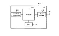
- FIG. 5 is a block diagram of the AP 400. As shown in FIG. 5, the AP 400 includes an antenna 401, a WLAN transceiver 410, a network interface 420, a memory 430, and a processor 440.
- the antenna 401 and the WLAN transceiver 410 are used for transmitting and receiving WLAN radio signals.
- the WLAN transceiver 410 converts the baseband signal output from the processor 440 into a WLAN radio signal and transmits it from the antenna 401. Also, the WLAN transceiver 410 converts the WLAN radio signal received by the antenna 401 into a baseband signal and outputs it to the processor 440.
- the network interface 420 is connected to the EPC 20 via a router or the like.
- the network interface 420 is used for communication with the eNB 200 via the EPC 20.
- the memory 430 stores a program executed by the processor 440 and information used for processing by the processor 340.
- the processor 440 includes a baseband processor that performs modulation / demodulation and encoding / decoding of the baseband signal, and a CPU that executes programs stored in the memory 430 and performs various processes.
- the processor 440 executes various processes and various communication protocols described later.
- the memory 430 may be integrated with the processor 440, and this set (that is, a chip set) may be used as a processor constituting the control unit.
- FIG. 6 is a protocol stack diagram of a radio interface in the cellular communication system. As shown in FIG. 6, the radio interface protocol is divided into layers 1 to 3 of the OSI reference model, and layer 1 is a physical (PHY) layer. Layer 2 includes a MAC (Media Access Control) layer, an RLC (Radio Link Control) layer, and a PDCP (Packet Data Convergence Protocol) layer. Layer 3 includes an RRC (Radio Resource Control) layer.
- PHY Physical
- Layer 2 includes a MAC (Media Access Control) layer, an RLC (Radio Link Control) layer, and a PDCP (Packet Data Convergence Protocol) layer.
- Layer 3 includes an RRC (Radio Resource Control) layer.
- RRC Radio Resource Control
- the physical layer performs encoding / decoding, modulation / demodulation, antenna mapping / demapping, and resource mapping / demapping. Data is transmitted between the physical layer of the UE 100 and the physical layer of the eNB 200 via a physical channel.
- the MAC layer performs data priority control, retransmission processing by hybrid ARQ (HARQ), and the like. Data is transmitted via the transport channel between the MAC layer of the UE 100 and the MAC layer of the eNB 200.
- the MAC layer of the eNB 200 includes a uplink / downlink transport format (transport block size, modulation / coding scheme, and the like) and a scheduler that selects allocated resource blocks.
- the RLC layer transmits data to the RLC layer on the receiving side using the functions of the MAC layer and the physical layer. Data is transmitted between the RLC layer of the UE 100 and the RLC layer of the eNB 200 via a logical channel.
- the PDCP layer performs header compression / decompression and encryption / decryption.
- the RRC layer is defined only in the control plane. Control messages (RRC messages) for various settings are transmitted between the RRC layer of the UE 100 and the RRC layer of the eNB 200.
- the RRC layer controls the logical channel, the transport channel, and the physical channel according to establishment, re-establishment, and release of the radio bearer.
- RRC connection When there is a connection (RRC connection) between the RRC of the UE 100 and the RRC of the eNB 200, the UE 100 is in a connected state (RRC connected state). Otherwise, the UE 100 is in an idle state (RRC idle state).
- the NAS (Non-Access Stratum) layer located above the RRC layer performs session management and mobility management.
- FIG. 7 is a configuration diagram of a radio frame used in the LTE system.
- the LTE system uses OFDMA (Orthogonal Frequency Division Multiplexing Access) for the downlink and SC-FDMA (Single Carrier Division Multiple Access) for the uplink.
- OFDMA Orthogonal Frequency Division Multiplexing Access
- SC-FDMA Single Carrier Division Multiple Access
- the radio frame is composed of ten subframes arranged in the time direction, and each subframe is composed of two slots arranged in the time direction.
- the length of each subframe is 1 ms, and the length of each slot is 0.5 ms.
- Each subframe includes a plurality of resource blocks (RB) in the frequency direction and includes a plurality of symbols in the time direction.
- a guard interval called a cyclic prefix (CP) is provided at the head of each symbol.
- the resource block includes a plurality of subcarriers in the frequency direction.
- a radio resource unit composed of one subcarrier and one symbol is called a resource element (RE).
- RE resource element
- frequency resources can be specified by resource blocks, and time resources can be specified by subframes (or slots).
- the UE 100 has a collocated AP list (co-located AP list).
- UE100 and eNB200 share a collocated AP list.
- the collocated AP list includes a cell ID of a small cell managed by the HeNB 300 that is a side-by-side type arranged at the same location as the AP 400, and location information of the HeNB 300.
- the UE 100 obtains a collocated AP list from eNB 200. For example, the UE 100 receives the collocated AP list from the eNB 200 at the time of establishing a connection, executing a handover, or changing the paging area.
- the eNB 200 may transmit the collocated AP list to the UE 100 based on capability information indicating that the UE 100 supports both cellular communication and WLAN communication methods.
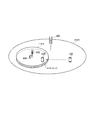
- FIG. 8 is a diagram illustrating a positional relationship between the UE 100, the eNB 200, the HeNB 300, and the AP 400.
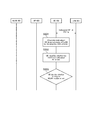
- FIG. 9 is a sequence diagram for explaining an operation according to the first embodiment.
- the UE 100 is located in a large cell managed by the eNB 200. Moreover, HeNB300 and AP400 are arrange
- the eNB 200 and the HeNB 300 operate in the same frequency band. Moreover, in this embodiment, UE100 will move to the direction of HeNB300, and description is advanced on the assumption that it enters into the coverage of a small cell (and the coverage of AP400). Therefore, the UE 100 has not found the AP 400.
- the WLAN transceiver 112 of the UE 100 is in an off state.
- the UE 100 shares the collocated AP list with the eNB 200. That is, the UE 100 has a collocated AP list.
- step S101 the HeNB 300 broadcasts a reference signal including a cell ID (Cell ID).
- Cell ID a cell ID
- the UE 100 receives the reference signal. Thereby, UE100 detects that it exists near HeNB300.
- step S102 the UE 100 specifies whether or not the HeNB 300 that has transmitted the reference signal is a side-by-side type. Specifically, the UE 100 confirms whether the cell ID included in the collocated AP list matches the cell ID included in the reference signal.
- the UE 100 specifies that the HeNB 300 is a side-by-side type. That is, the UE 100 recognizes that the HeNB 300 is a side-by-side type.
- the UE 100 specifies that the HeNB 300 is not the co-located type. That is, the UE 100 recognizes that the HeNB 300 is not a side-by-side type.
- step S103 the UE 100 determines whether or not to switch the WLAN transceiver 112 (WLAN module) to the on state.
- the UE100 switches WLAN transceiver 112 from an OFF state to an ON state, when HeNB300 is a coexisting type.
- the HeNB 300 is not a side-by-side type, the UE 100 maintains the WLAN transceiver 112 in an off state.
- the UE 100 switches the WLAN transceiver 112 to the on state to turn on the scan function and starts a scan for discovering the AP 400.
- FIG. 10 is a sequence diagram for explaining an operation according to the modification of the first embodiment.
- the eNB 200 and the HeNB 300 are operating in different frequency bands. Therefore, UE100 cannot receive the reference signal from HeNB300.
- the UE 100 has a white list (CSG white list) including the location information of the CSG cell to which the UE 100 has access rights and the cell ID of the CSG cell.
- CSG white list including the location information of the CSG cell to which the UE 100 has access rights and the cell ID of the CSG cell.
- the UE 100 moves in the direction of the HeNB 300 and proceeds with the description on the assumption that it enters the small cell coverage (and the AP coverage). Other conditions are the same as those in the first embodiment.
- the UE 100 shares the collocated AP list with the eNB 200.
- step S201 the UE 100 detects proximity to the HeNB 300 based on the white list (Proximity Estimate). Thereby, UE100 detects that it exists near HeNB300.
- step S202 the UE 100 confirms whether the cell ID included in the collocated AP list matches the cell ID of the CSG cell included in the white list.
- the UE 100 specifies that the HeNB 300 is a side-by-side type. That is, the UE 100 recognizes that the HeNB 300 is a side-by-side type.
- the UE 100 specifies that the HeNB 300 is not a co-located type. That is, the UE 100 recognizes that the HeNB 300 is not a side-by-side type.
- Step S203 corresponds to step S103 in FIG.
- the UE 100 detects that the UE 100 exists near the HeNB 300. Further, the UE 100 starts scanning for discovering the AP 400 when the AP 400 has not been discovered and when the UE 100 recognizes that the HeNB 300 is a side-by-side type. Thereby, when AP400 exists near UE100 located near HeNB300, since scanning can be started, AP400 can be discovered efficiently.
- the UE 100 recognizes that the HeNB 300 is a side-by-side type based on the collocated AP list. Thereby, UE100 can discover AP400 efficiently even when it is a case where it is a case where it is not connected with eNB200.
- the UE 100 detects that the UE 100 is present near the HeNB 300 by receiving the cell ID from the HeNB 300. Thereby, UE100 can detect that it exists near HeNB300 only by receiving the reference signal containing cell ID of HeNB300.
- the UE 100 when the eNB 200 and the HeNB 300 are operated in different frequency bands, the UE 100 detects that the UE 100 is present near the HeNB 300 based on the position information included in the white list. Thereby, even if eNB200 and HeNB300 are operate
- the UE 100 acquires a collocated AP list from the eNB 200. Thereby, UE100 can discover AP400 efficiently even when it is a case where it is a case where it is not connected with eNB200.
- FIG. 11 is a sequence diagram for explaining an operation according to the second embodiment.
- the UE 100 determines whether or not the HeNB 300 is a side-by-side type using the collocated AP list.
- the eNB 200 determines whether or not the HeNB 300 is a side-by-side type using the collocated AP list. Therefore, the eNB 200 has a collocated AP list, and the UE 100 does not have a collocated AP list.
- the eNB 200 and the HeNB 300 operate in the same frequency band. Further, in this embodiment, the UE 100 moves in the direction of the HeNB 300 and proceeds with the description on the assumption that the UE 100 enters small cell coverage (and AP coverage). Other conditions are the same as those in the first embodiment.
- step S301 the HeNB 300 broadcasts a reference signal including a cell ID (Cell ID).
- Cell ID a cell ID
- the UE 100 receives the reference signal. Thereby, UE100 detects that it exists near HeNB300.
- step S302 the UE 100 transmits a measurement report (Measurement Report) of received power of the reference signal to the eNB 200.
- the eNB 200 receives the measurement report.
- UE100 notifies eNB200 that UE100 exists near HeNB300 by a measurement report.
- the measurement report includes the cell ID of HeNB 300 included in the reference signal.
- step S303 the eNB 200 determines whether or not the cell ID included in the measurement report matches the cell ID of the collocated AP list. That is, eNB200 specifies whether HeNB300 which transmitted the reference signal is a coexistence type.
- step S304 when the cell ID included in the measurement report matches the cell ID of the collocated AP list (in the case of Yes), the eNB 200 notifies the UE 100 that the HeNB 300 is a co-located type. In addition, the eNB 200 notifies the identifier (for example, SSID (Service Set Identifier) or BSSID (Basic Service Set Identifier)) of the AP 400 disposed in the same place as the HeNB 300.
- SSID Service Set Identifier
- BSSID Basic Service Set Identifier
- the eNB 200 ends the process.
- step S305 the UE 100 specifies that the HeNB 300 is the side-by-side type by notifying that the HeNB 300 is the side-by-side type from the eNB 200.
- Step S306 corresponds to step S103 in FIG.
- the UE 100 may perform scanning based on the identifier of the AP 400 when the scanning function is switched to the on state.
- FIG. 12 is a sequence diagram for explaining the operation according to the modified example of the second embodiment.
- the eNB 200 and the HeNB 300 operate in different frequency bands as in the modification according to the first embodiment. Therefore, UE100 cannot receive the reference signal from HeNB300. Further, in this embodiment, the UE 100 moves in the direction of the HeNB 300 and proceeds with the description on the assumption that the UE 100 enters small cell coverage (and AP coverage). Other conditions are the same as those in the second embodiment.
- Step S401 in FIG. 12 corresponds to step S201 in FIG.
- step S402 the UE 100 transmits, to the eNB 200, a proximity notification (Proximity Indication) indicating that the UE 100 is near the CSG cell.
- the eNB 200 receives the proximity notification.
- the proximity notification includes the cell ID of the CSG cell.
- step S403 the eNB 200 determines whether or not the cell ID included in the proximity notification matches the cell ID of the collocated AP list. That is, eNB200 specifies whether HeNB300 existing in the vicinity of UE100 is a side-by-side type.
- step S404 when the cell ID included in the proximity notification matches the cell ID of the collocated AP list, the eNB 200 performs collocation notification (Collation Indication) indicating that the HeNB 300 is a co-located type.
- the UE 100 receives the collocation notification.
- the eNB 200 transmits a reconfiguration notification including a collocation notification.
- the reconfiguration notification includes measurement settings (Measurement Config.).
- the eNB 200 may transmit a collocation notification and a reconfiguration notification separately.
- the eNB 200 does not transmit the collocation notification.
- step S405 the UE 100 specifies that the HeNB 300 is a side-by-side type based on the collocation notification.
- Step S406 corresponds to step S103 in FIG.
- the eNB 200 notifies the UE 100 that the HeNB 300 is a side-by-side type. Thereby, since UE100 does not need to perform a process in order to confirm whether HeNB300 is a coexistence type based on the collocated AP list, the processing load of UE100 can be reduced.
- the UE 100 when the eNB 200 and the HeNB 300 are operated in the same frequency band, the UE 100 notifies the eNB 200 that it exists near the HeNB 300 by a measurement report of received power from the HeNB 300. Further, when the eNB 200 and the HeNB 300 are operated in different frequency bands, the UE 100 notifies the eNB 200 that the eNB 200 exists near the HeNB 300 by a proximity notification. Thereby, since UE100 does not need to perform the new notification for notifying that it exists near HeNB300, the processing load of UE100 can be reduced.
- eNB200 specified whether HeNB300 was a coexistence type, it is not restricted to this.
- the host device (e.g., MME) of the eNB 200 may specify whether or not the HeNB 300 is a side-by-side type. In this case, the host device of the eNB 200 has a collocated AP list.
- eNB200 transmitted the collocation notification to UE100 with the reset notification, it is not restricted to this.
- the eNB 200 may transmit the identifier of the AP 400 to the UE 100 instead of the collocation notification.
- the measurement trigger Measurement Trigger
- the UE 100 can turn on the scan function and start a scan for finding the identifier of the transmitted AP 400.
- scanning is started by switching the WLAN transceiver 112 from the off state to the on state.
- the present invention is not limited to this.
- the scan function may be switched to an on state. Thereby, UE100 starts a scan.
- the scan function is on but the scan is stopped (for example, a scan function in which a mode for periodically scanning or a mode for starting a scan based on a specific event is selected is on.
- the UE 100 may restart (start) the scan by using the recognition that the HeNB 300 is the side-by-side type as a trigger.
- the HeNB 300 is described as an example of the small cell base station, but is not limited thereto.
- the small cell base station may be a femto cell or a pico cell that manages a small cell.
- the UE 100 performs the processing of the above-described embodiment based on the received reference signal. May be executed.
- the HeNB 300 may notify the UE by broadcast or unicast that the local station is a co-located type. Thereby, UE100 recognizes that HeNB300 is a side-by-side type. Thereby, since UE100 does not need to perform a process in order to confirm whether HeNB300 is a coexistence type based on the collocated AP list, the processing load of UE100 can be reduced.
- the eNB 200 when the eNB 200 is directly connected to the AP 400, the eNB 200 transmits information specifying a channel for performing a scan for the AP 100 to find the AP 400, together with a notification that the local station is a co-located type. Good. Thereby, UE100 can discover AP efficiently by scanning based on the information which designates a channel.
- the eNB 200 may transmit a measurement setting (Measurement Config.) To the UE 100 so that a measurement report (Measurement Report) is performed only when a small cell existing in the collocated AP list is recognized.
- the eNB 200 can notify the UE 100 of the identifier of the AP 400 as soon as the measurement report is received from the UE 100.
- the collocated AP list may include information indicating an identifier of the AP 400 arranged at the same location as the HeNB 300 that is the side-by-side type, in addition to the cell ID of the small cell.
- the UE 100 may perform scanning based on the identifier of the AP 400 corresponding to the recognized HeNB 300.
- the LTE system is described as an example of the cellular communication system.
- the present invention is not limited to the LTE system, and the present invention may be applied to a system other than the LTE system.
- a user terminal having a cellular communication unit and a wireless LAN communication unit can efficiently find an access point, which is useful in the mobile communication field. is there.
Landscapes
- Engineering & Computer Science (AREA)
- Computer Networks & Wireless Communication (AREA)
- Signal Processing (AREA)
- Computer Security & Cryptography (AREA)
- Mobile Radio Communication Systems (AREA)
- Telephonic Communication Services (AREA)
Abstract
La présente invention concerne un procédé de commande de communication destiné à relier un système de communication cellulaire à un système de réseau local sans fil. Le procédé de commande de communication comprend : une étape de détection dans laquelle un terminal d'utilisateur comprenant une unité de communication cellulaire et une unité de communication de réseau local sans fil détecte l'existence du terminal d'utilisateur à proximité d'une station de base de petite cellule ; une étape de reconnaissance dans laquelle le terminal d'utilisateur reconnait que la station de base de petite cellule est de type colocalisation positionnée au même endroit qu'un point d'accès au réseau local sans fil ; et une étape de démarrage de balayage dans laquelle le terminal d'utilisateur commence le balayage pour découvrir le point d'accès au réseau local sans fil lorsque le terminal d'utilisateur reconnait que la station de base de petite cellule est du type colocalisation, et lorsque le terminal d'utilisateur n'a pas découvert le point d'accès au réseau local sans fil.
Priority Applications (2)
| Application Number | Priority Date | Filing Date | Title |
|---|---|---|---|
| EP14795344.2A EP2996384A4 (fr) | 2013-05-10 | 2014-05-08 | Procédé de commande de communication, terminal d'utilisateur, et processeur |
| US14/890,370 US9668202B2 (en) | 2013-05-10 | 2014-05-08 | Communication control method, user terminal, and processor |
Applications Claiming Priority (2)
| Application Number | Priority Date | Filing Date | Title |
|---|---|---|---|
| JP2013100781A JP6147562B2 (ja) | 2013-05-10 | 2013-05-10 | 通信制御方法、ユーザ端末、及び、プロセッサ |
| JP2013-100781 | 2013-05-10 |
Publications (1)
| Publication Number | Publication Date |
|---|---|
| WO2014181832A1 true WO2014181832A1 (fr) | 2014-11-13 |
Family
ID=51867309
Family Applications (1)
| Application Number | Title | Priority Date | Filing Date |
|---|---|---|---|
| PCT/JP2014/062372 WO2014181832A1 (fr) | 2013-05-10 | 2014-05-08 | Procédé de commande de communication, terminal d'utilisateur, et processeur |
Country Status (4)
| Country | Link |
|---|---|
| US (1) | US9668202B2 (fr) |
| EP (1) | EP2996384A4 (fr) |
| JP (1) | JP6147562B2 (fr) |
| WO (1) | WO2014181832A1 (fr) |
Families Citing this family (6)
| Publication number | Priority date | Publication date | Assignee | Title |
|---|---|---|---|---|
| KR101878210B1 (ko) * | 2013-11-29 | 2018-07-13 | 삼성전자주식회사 | 무선 통신 시스템에서 소형 셀을 발견하기 위한 장치 및 방법 |
| EP3151617B1 (fr) * | 2014-06-24 | 2019-05-29 | Huawei Technologies Co. Ltd. | Procédé de localisation, équipement utilisateur, et station de base |
| WO2017026720A1 (fr) * | 2015-08-12 | 2017-02-16 | 엘지전자 주식회사 | Procédé et dispositif pour terminal effectuant une mesure de wlan |
| ES2818117T3 (es) * | 2015-10-05 | 2021-04-09 | Ericsson Telefon Ab L M | Gestionar problemas de enlace de radio entre un dispositivo inalámbrico y un nodo en servicio en un sistema de comunicación inalámbrico |
| ES2907986T3 (es) * | 2016-01-14 | 2022-04-27 | Ericsson Telefon Ab L M | Enfoque de personalización para nodos cooperantes que interaccionan a través de un estándar |
| CN109673022B (zh) * | 2018-12-14 | 2020-08-04 | 浙江三维通信科技有限公司 | 一种利用多个侦测基站的信令管控lte终端的方法及系统 |
Citations (2)
| Publication number | Priority date | Publication date | Assignee | Title |
|---|---|---|---|---|
| WO2010146785A1 (fr) * | 2009-06-15 | 2010-12-23 | 日本電気株式会社 | Système de communication sans fil, et procédé de communication sans fil |
| JP2011511496A (ja) * | 2008-01-11 | 2011-04-07 | テレフオンアクチーボラゲット エル エム エリクソン(パブル) | Wlanを検出する方法、基地局、移動局、通信システム、及びコンピュータプログラム |
Family Cites Families (9)
| Publication number | Priority date | Publication date | Assignee | Title |
|---|---|---|---|---|
| KR100458442B1 (ko) * | 2002-11-15 | 2004-11-26 | 한국전자통신연구원 | 이동통신 기지국의 방송정보를 이용한 무선랜 에이피 자동탐색 장치 및 그 방법 |
| WO2004114691A1 (fr) * | 2003-06-18 | 2004-12-29 | Qualcomm Incorporated | Systeme et procede de transfert immediat dans un reseau gsm |
| US20070297358A1 (en) * | 2006-06-22 | 2007-12-27 | Chang Henry S | Efficient WLAN location in a wireless device |
| KR100844349B1 (ko) | 2006-12-01 | 2008-07-07 | 삼성전자주식회사 | 휴대용 단말기에서 무선랜 검색 방법 및 장치 |
| EP2073445B1 (fr) * | 2007-12-21 | 2014-07-16 | TELEFONAKTIEBOLAGET LM ERICSSON (publ) | Procédé, station de base, station mobile, système de télécommunication, et programme informatique pour détecter un réseau local |
| US9125118B2 (en) * | 2010-12-03 | 2015-09-01 | Lg Electronics Inc. | Method and apparatus for performing access control in wireless communication system |
| US8537799B2 (en) * | 2010-12-31 | 2013-09-17 | Qualcomm Incorporated | Coexistence mechanism for collocated WLAN and WWAN communication devices |
| US20150004969A1 (en) * | 2013-01-17 | 2015-01-01 | Seunghee Han | Discovery signal in cluster-based small cell |
| US10104540B2 (en) * | 2013-01-23 | 2018-10-16 | Qualcomm Incorporated | Determining to use multi-RAN interworking by correlating different RAN identifiers |
-
2013
- 2013-05-10 JP JP2013100781A patent/JP6147562B2/ja not_active Expired - Fee Related
-
2014
- 2014-05-08 EP EP14795344.2A patent/EP2996384A4/fr not_active Withdrawn
- 2014-05-08 WO PCT/JP2014/062372 patent/WO2014181832A1/fr active Application Filing
- 2014-05-08 US US14/890,370 patent/US9668202B2/en active Active
Patent Citations (2)
| Publication number | Priority date | Publication date | Assignee | Title |
|---|---|---|---|---|
| JP2011511496A (ja) * | 2008-01-11 | 2011-04-07 | テレフオンアクチーボラゲット エル エム エリクソン(パブル) | Wlanを検出する方法、基地局、移動局、通信システム、及びコンピュータプログラム |
| WO2010146785A1 (fr) * | 2009-06-15 | 2010-12-23 | 日本電気株式会社 | Système de communication sans fil, et procédé de communication sans fil |
Non-Patent Citations (4)
| Title |
|---|
| ACER INCORPORATED: "Discussion on provision of discovery information", 3GPP TSG-RAN WG2 #81-BIS R2-131154, 15 April 2013 (2013-04-15), XP050699267 * |
| BROADCOM CORPORATION: "Air-Interface Enhancement Proposals for WLAN/3GPP Radio Interworking", 3GPP TSG-RAN WG2 MEETING #81-BIS R2-131384, 15 April 2013 (2013-04-15), XP050699348 * |
| INTEL CORPORATION: "Email discussion report on WLAN/3GPP radio interworking scenarios", 3GPP TSG RAN2 MEETING #81BIS R2-131340, 15 April 2013 (2013-04-15), XP050699489 * |
| MEDIATEK INC.: "Reduce Battery Consumption and Improve WLAN Utilization", 3GPP TSG RAN WG2 #81BIS R2-131032, 15 April 2013 (2013-04-15), XP050699215 * |
Also Published As
| Publication number | Publication date |
|---|---|
| JP6147562B2 (ja) | 2017-06-14 |
| US9668202B2 (en) | 2017-05-30 |
| EP2996384A4 (fr) | 2017-01-04 |
| EP2996384A1 (fr) | 2016-03-16 |
| US20160112937A1 (en) | 2016-04-21 |
| JP2014220779A (ja) | 2014-11-20 |
Similar Documents
| Publication | Publication Date | Title |
|---|---|---|
| US11178721B2 (en) | Mobile communication system, user terminal, and base station | |
| US10631354B2 (en) | User terminal and access point | |
| JP6328132B2 (ja) | 移動通信システム及びユーザ端末 | |
| JP6224861B2 (ja) | ユーザ端末、プロセッサ、及び方法 | |
| US10750480B2 (en) | Mobile communication system, user terminal, base station, processor, and communication control method | |
| EP3142421B1 (fr) | Service de proximité de dispositif à dispositif pour des dispositifs servis par différentes cellules | |
| WO2014181832A1 (fr) | Procédé de commande de communication, terminal d'utilisateur, et processeur | |
| JPWO2016175254A1 (ja) | 無線通信システム及び無線通信方法 | |
| JP6615729B2 (ja) | 通信方法、ユーザ端末及びプロセッサ | |
| JP6302129B1 (ja) | 基地局及びプロセッサ | |
| US20160057792A1 (en) | Mobile communication system, base station, and user terminal |
Legal Events
| Date | Code | Title | Description |
|---|---|---|---|
| 121 | Ep: the epo has been informed by wipo that ep was designated in this application |
Ref document number: 14795344 Country of ref document: EP Kind code of ref document: A1 |
|
| NENP | Non-entry into the national phase |
Ref country code: DE |
|
| WWE | Wipo information: entry into national phase |
Ref document number: 14890370 Country of ref document: US |
|
| WWE | Wipo information: entry into national phase |
Ref document number: 2014795344 Country of ref document: EP |