WO2014181832A1 - Communication control method, user terminal, and processor - Google Patents
Communication control method, user terminal, and processor Download PDFInfo
- Publication number
- WO2014181832A1 WO2014181832A1 PCT/JP2014/062372 JP2014062372W WO2014181832A1 WO 2014181832 A1 WO2014181832 A1 WO 2014181832A1 JP 2014062372 W JP2014062372 W JP 2014062372W WO 2014181832 A1 WO2014181832 A1 WO 2014181832A1
- Authority
- WO
- WIPO (PCT)
- Prior art keywords
- base station
- user terminal
- small cell
- cell base
- wireless lan
- Prior art date
Links
Images


Classifications
-
- H—ELECTRICITY
- H04—ELECTRIC COMMUNICATION TECHNIQUE
- H04W—WIRELESS COMMUNICATION NETWORKS
- H04W48/00—Access restriction; Network selection; Access point selection
- H04W48/16—Discovering, processing access restriction or access information
-
- H—ELECTRICITY
- H04—ELECTRIC COMMUNICATION TECHNIQUE
- H04W—WIRELESS COMMUNICATION NETWORKS
- H04W16/00—Network planning, e.g. coverage or traffic planning tools; Network deployment, e.g. resource partitioning or cells structures
- H04W16/24—Cell structures
- H04W16/32—Hierarchical cell structures
-
- H—ELECTRICITY
- H04—ELECTRIC COMMUNICATION TECHNIQUE
- H04W—WIRELESS COMMUNICATION NETWORKS
- H04W24/00—Supervisory, monitoring or testing arrangements
- H04W24/10—Scheduling measurement reports ; Arrangements for measurement reports
-
- H—ELECTRICITY
- H04—ELECTRIC COMMUNICATION TECHNIQUE
- H04W—WIRELESS COMMUNICATION NETWORKS
- H04W48/00—Access restriction; Network selection; Access point selection
- H04W48/02—Access restriction performed under specific conditions
- H04W48/04—Access restriction performed under specific conditions based on user or terminal location or mobility data, e.g. moving direction, speed
-
- H—ELECTRICITY
- H04—ELECTRIC COMMUNICATION TECHNIQUE
- H04W—WIRELESS COMMUNICATION NETWORKS
- H04W84/00—Network topologies
- H04W84/02—Hierarchically pre-organised networks, e.g. paging networks, cellular networks, WLAN [Wireless Local Area Network] or WLL [Wireless Local Loop]
- H04W84/04—Large scale networks; Deep hierarchical networks
- H04W84/042—Public Land Mobile systems, e.g. cellular systems
- H04W84/045—Public Land Mobile systems, e.g. cellular systems using private Base Stations, e.g. femto Base Stations, home Node B
-
- H—ELECTRICITY
- H04—ELECTRIC COMMUNICATION TECHNIQUE
- H04W—WIRELESS COMMUNICATION NETWORKS
- H04W84/00—Network topologies
- H04W84/02—Hierarchically pre-organised networks, e.g. paging networks, cellular networks, WLAN [Wireless Local Area Network] or WLL [Wireless Local Loop]
- H04W84/10—Small scale networks; Flat hierarchical networks
- H04W84/12—WLAN [Wireless Local Area Networks]
-
- H—ELECTRICITY
- H04—ELECTRIC COMMUNICATION TECHNIQUE
- H04W—WIRELESS COMMUNICATION NETWORKS
- H04W48/00—Access restriction; Network selection; Access point selection
- H04W48/18—Selecting a network or a communication service
-
- H—ELECTRICITY
- H04—ELECTRIC COMMUNICATION TECHNIQUE
- H04W—WIRELESS COMMUNICATION NETWORKS
- H04W84/00—Network topologies
- H04W84/02—Hierarchically pre-organised networks, e.g. paging networks, cellular networks, WLAN [Wireless Local Area Network] or WLL [Wireless Local Loop]
- H04W84/04—Large scale networks; Deep hierarchical networks
- H04W84/042—Public Land Mobile systems, e.g. cellular systems
Definitions
- the present invention relates to a communication control method, a user terminal, and a processor for linking a cellular communication system with a wireless LAN system.
- wireless LAN access points (hereinafter referred to as “access points”) managed by operators of cellular communication systems are increasing.
- wireless LAN communication when performing data communication (hereinafter referred to as “wireless LAN communication”) in the wireless LAN system, the user terminal performs scanning in order to find an access point.
- a user terminal that has found an access point by scanning performs wireless LAN communication by connecting to the access point.
- the present invention provides a communication control method, a user terminal, and a processor that enable a user terminal having a cellular communication unit and a wireless LAN communication unit to efficiently find an access point.
- a communication control method for linking a cellular communication system with a wireless LAN system detects that a user terminal having a cellular communication unit and a wireless LAN communication unit exists near a small cell base station. Detecting step, recognizing that the user terminal is a co-located type in which the small cell base station is located at the same location as the wireless LAN access point, and the user terminal that the small cell base station And a scan start step of starting a scan for finding the wireless LAN access point when the wireless LAN access point is not found when the wireless LAN access point is recognized.
- the communication control method, user terminal, and processor according to the present invention enable a user terminal having a cellular communication unit and a wireless LAN communication unit to efficiently discover an access point.
- FIG. 1 is a system configuration diagram according to the first embodiment and the second embodiment.
- FIG. 2 is a block diagram of a UE (user terminal) according to the first embodiment and the second embodiment.
- FIG. 3 is a block diagram of an eNB (cellular base station) according to the first embodiment and the second embodiment.
- FIG. 4 is a block diagram of the HeNB according to the first embodiment and the second embodiment.
- FIG. 5 is a block diagram of an AP (access point) according to the first embodiment and the second embodiment.
- FIG. 6 is a protocol stack diagram of a radio interface in the LTE system.
- FIG. 7 is a configuration diagram of a radio frame used in the LTE system.
- FIG. 8 is a diagram illustrating a positional relationship between the UE 100, the eNB 200, the HeNB 300, and the AP 400.
- FIG. 9 is a sequence diagram for explaining an operation according to the first embodiment.
- FIG. 10 is a sequence diagram for explaining an operation according to the modification of the first embodiment.
- FIG. 11 is a sequence diagram for explaining an operation according to the second embodiment.
- FIG. 12 is a sequence diagram for explaining the operation according to the modified example of the second embodiment.
- the communication control method is a communication control method for linking a cellular communication system with a wireless LAN system.
- the communication control method includes a detection step of detecting that a user terminal having a cellular communication unit and a wireless LAN communication unit is present near a small cell base station, and the user terminal is configured such that the small cell base station is a wireless LAN.
- a recognition step for recognizing that it is a co-located type arranged in the same place as the access point, and a case where the user terminal recognizes that the small cell base station is the co-located type, and the wireless LAN access
- a scan start step for starting a scan for finding the wireless LAN access point when no point is found.
- the user terminal determines that the small cell base station is the co-located type based on a co-located list related to the small cell base station that is the co-located type. recognize.
- the user terminal detects that the user terminal is present near the small cell base station by receiving a cell identifier from the small cell base station, In the recognizing step, the user terminal recognizes that the small cell base station is of the co-located type when the cell identifier matches the cell identifier included in the co-located list.
- the user terminal in the detection step, is present near the small cell base station based on location information included in a white list related to a specific cell to which the user terminal has access rights.
- the recognition step when the cell identifier included in the white list and the cell identifier included in the side-by-side list match, Recognize that.
- the communication control method further includes an acquisition step in which the user terminal acquires the side-by-side list from a base station that manages a larger cell than a small cell managed by the small cell base station.
- the communication control method When the communication control method according to the second embodiment detects that the user terminal is present near the small cell base station, the communication control method indicates that the user terminal is present near the small cell base station.
- the user terminal determines that the small cell base station is based on the notification in the base station notifying step. It recognizes that it is a type.
- the user terminal detects that the user terminal is present near the small cell base station by receiving a cell identifier from the small cell base station, In the user notification step, the user terminal notifies the base station that the user terminal is located near the small cell base station by a measurement report of received power from the small cell base station.
- the user terminal in the detection step, the user terminal is present near the small cell base station based on location information included in a white list related to a specific cell to which the user terminal has access rights.
- the user terminal In the user notification step, the user terminal notifies the base station that it is near the small cell base station by a proximity notification indicating that the user terminal is near the specific cell.
- the communication control method further includes a notification step in which the small cell base station notifies the user terminal that the local station is the co-located type, and in the recognition step, the user terminal When it is connected to the small cell base station and the notification in the notification step is received, the small cell base station recognizes that the small cell base station is the side-by-side type.
- the notification step when the small cell base station is directly connected to the wireless LAN access point, the channel that performs the scan together with the notification in the notification step Send information specifying.
- the user terminal is a user terminal having a cellular communication unit and a wireless LAN communication unit, and includes a control unit that performs control to detect the presence near a small cell base station, and the control unit includes:
- the small cell base station performs control for recognizing that the small cell base station is a coexisting type disposed at the same location as the wireless LAN access point, and the control unit has recognized that the small cell base station is the coexisting type In this case, when the wireless LAN access point is not found, a control for starting a scan for finding the wireless LAN access point is performed.
- the processor which concerns on embodiment is a processor with which the user terminal which has a cellular communication part and a wireless LAN communication part is provided, Comprising: The process which detects existing near a small cell base station is performed, The said small cell base station Executes a process of recognizing that the small cell base station is the side-by-side type, and performs processing for recognizing that the side-by-side type is located at the same location as the wireless LAN access point, and the wireless LAN When no access point is found, a process for starting a scan for finding the wireless LAN access point is executed.
- the case where the wireless terminal has not found the wireless LAN access point is the case where the wireless LAN access point has not been found since the wireless LAN communication unit is in the off state, and the wireless LAN communication unit Includes a case where the wireless LAN access point is not found because scanning is stopped.
- LTE system cellular communication system
- WLAN wireless LAN
- FIG. 1 is a system configuration diagram according to the first embodiment.
- the cellular communication system includes a plurality of UEs (User Equipment) 100, an E-UTRAN (Evolved Universal Terrestrial Radio Access Network) 10, and an EPC (Evolved Packet Core) 20.
- the E-UTRAN 10 corresponds to a radio access network.
- the EPC 20 corresponds to a core network.
- the UE 100 is a mobile radio communication device, and performs radio communication with a cell that has established a connection.
- UE100 is corresponded to a user terminal.
- the UE 100 is a terminal (dual terminal) that supports both cellular communication and WLAN communication methods.
- the E-UTRAN 10 includes an eNB 200 (evolved Node-B) and a HeNB 300 (Home evolved Node-B).
- the eNB 200 corresponds to a cellular base station.
- the eNB 200 manages one or a plurality of cells (large cells) and performs radio communication with the UE 100 that has established a connection (RRC connection) with the own cell.
- “cell” is used as a term indicating a minimum unit of a radio communication area, and is also used as a term indicating a function of performing radio communication with the UE 100.
- the eNB 200 has, for example, a radio resource management (RRM) function, a user data routing function, and a measurement control function for mobility control and scheduling.
- RRM radio resource management
- the eNB 200 is connected to each other via the X2 interface.
- the eNB 200 is connected to the MME / S-GW 500 included in the EPC 20 via the S1 interface.
- the HeNB 300 manages a specific cell (small cell) whose coverage is narrower than that of the large cell. HeNB300 performs radio
- the specific cell is referred to as a “CSG cell”, a “hybrid cell”, or an “open cell” depending on the set access mode.
- the CSG cell is a cell that can be accessed only by the UE 100 having the access right (referred to as “member UE”), and broadcasts the CSG ID.
- the UE 100 maintains a list (white list) of CSG IDs of CSG cells to which the UE 100 has access rights, and determines whether there is access rights based on the white list and the CSG ID broadcast by the CSG cell. To do.
- the hybrid cell is a cell in which the member UE is handled more favorably than the non-member UE, and broadcasts information indicating that the cell is a cell released to the non-member UE in addition to the CSG ID.
- the UE 100 determines whether or not there is an access right based on the white list and the CSG ID broadcast by the hybrid cell.
- An open cell is a cell that is handled equally by the UE 100 regardless of whether it is a member, and does not broadcast a CSG ID. From the viewpoint of UE 100, an open cell is equivalent to a cell.
- the EPC 20 includes a plurality of MME (Mobility Management Entity) / S-GW (Serving-Gateway) 500.
- MME Mobility Management Entity
- S-GW Serving-Gateway
- the MME is a network node that performs various types of mobility control for the UE 100, and corresponds to a control station.
- the S-GW is a network node that performs transfer control of user data, and corresponds to an exchange.
- the MME authenticates the UE 100 with respect to the access right to the CSG cell.
- the WLAN system includes a WLAN AP (hereinafter referred to as “AP”) 400.
- the WLAN system is configured in accordance with, for example, IEEE 802.11 standards.
- AP 400 communicates with UE 100 in a frequency band (WLAN frequency band) different from the cellular frequency band.
- the AP 400 is connected to the EPC 20 via a router or the like.
- HeNB300 is a side-by-side type.
- the HeNB 300 and the AP 400 may be an integrated type arranged in the same casing.
- the HeNB 300 and the AP 400 may be directly connected by an arbitrary interface of the operator.
- HeNB300 and AP400 may share a control part.
- FIG. 2 is a block diagram of the UE 100.
- the UE 100 includes antennas 101 and 102, a cellular transceiver (cellular communication unit) 111, a WLAN transceiver (wireless LAN communication unit) 112, a user interface 120, a GNSS (Global Navigation Satellite System). )
- the receiver 130, the battery 140, the memory 150, and the processor 160 constitute a control unit.
- the UE 100 may not have the GNSS receiver 130.
- the memory 150 may be integrated with the processor 160, and this set (that is, a chip set) may be used as the processor 160 'that constitutes the control unit.
- the antenna 101 and the cellular transceiver 111 are used for transmitting and receiving cellular radio signals.
- the cellular transceiver 111 converts the baseband signal output from the processor 160 into a cellular radio signal and transmits it from the antenna 101.
- the cellular transceiver 111 converts a cellular radio signal received by the antenna 101 into a baseband signal and outputs it to the processor 160.
- the antenna 102 and the WLAN transceiver 112 are used for transmitting and receiving WLAN radio signals.
- the WLAN transceiver 112 converts the baseband signal output from the processor 160 into a WLAN radio signal and transmits it from the antenna 102. Further, the WLAN transceiver 112 converts the WLAN radio signal received by the antenna 102 into a baseband signal and outputs the baseband signal to the processor 160.
- the WLAN transceiver 112 performs a scan to find the AP 400.
- the user interface 120 is an interface with a user who owns the UE 100, and includes, for example, a display, a microphone, a speaker, and various buttons.
- the user interface 120 receives an input from the user and outputs a signal indicating the content of the input to the processor 160.
- the GNSS receiver 130 receives a GNSS signal and outputs the received signal to the processor 160 in order to obtain location information indicating the geographical location of the UE 100.
- the battery 140 stores power to be supplied to each block of the UE 100.
- the memory 150 stores a program executed by the processor 160 and information used for processing by the processor 160.
- the processor 160 includes a baseband processor that performs modulation / demodulation and encoding / decoding of a baseband signal, and a CPU that executes programs stored in the memory 150 and performs various processes.
- the processor 160 may further include a codec that performs encoding / decoding of an audio / video signal.
- the processor 160 executes various processes and various communication protocols described later. Specifically, for example, the processor 160 performs control to cause the WLAN transceiver 112 to perform scanning. The processor 160 performs control for the WLAN transceiver 112 to start scanning when the AP 400 has not been found and when it is recognized that the HeNB 300 is the side-by-side type.
- FIG. 3 is a block diagram of the eNB 200.
- the eNB 200 includes an antenna 201, a cellular transceiver 210, a network interface 220, a memory 230, and a processor 240.
- the memory 230 and the processor 240 constitute a control unit.
- the memory 230 may be integrated with the processor 240, and this set (that is, a chip set) may be a processor constituting the control unit.
- the antenna 201 and the cellular transceiver 210 are used for transmitting and receiving cellular radio signals.
- the cellular transceiver 210 converts the baseband signal output from the processor 240 into a cellular radio signal and transmits it from the antenna 201.
- the cellular transceiver 210 converts a cellular radio signal received by the antenna 201 into a baseband signal and outputs it to the processor 240.
- the network interface 220 is connected to the adjacent eNB 200 or the adjacent HeNB 300 via the X2 interface, and is connected to the MME / S-GW 500 via the S1 interface.
- the network interface 220 is used for communication with the AP 400 via the EPC 20.
- the memory 230 stores a program executed by the processor 240 and information used for processing by the processor 240.
- the processor 240 includes a baseband processor that performs modulation / demodulation and encoding / decoding of a baseband signal, and a CPU that executes a program stored in the memory 230 and performs various processes.
- the processor 240 executes various processes and various communication protocols described later.
- FIG. 4 is a block diagram of the HeNB 300.
- the HeNB 300 includes an antenna 301, a cellular transceiver 310, a network interface 320, a memory 330, and a processor 340.
- the memory 330 and the processor 340 constitute a control unit.
- the memory 330 may be integrated with the processor 340, and this set (that is, a chip set) may be a processor constituting the control unit.
- the antenna 301 and the cellular transceiver 310 are used for transmitting and receiving cellular radio signals.
- the cellular transceiver 310 converts the baseband signal output from the processor 340 into a cellular radio signal and transmits it from the antenna 301.
- the cellular transceiver 310 converts a cellular radio signal received by the antenna 301 into a baseband signal and outputs it to the processor 340.
- the cellular transceiver 310 forms a CSG cell.
- the network interface 320 is connected to the adjacent eNB 200 or the adjacent HeNB 300 via the X2 interface, and is connected to the MME / S-GW 500 via the S1 interface.
- the network interface 320 is used for communication with the AP 400 via the EPC 20.
- the memory 330 stores a program executed by the processor 340 and information used for processing by the processor 340.
- the processor 340 includes a baseband processor that performs modulation / demodulation and encoding / decoding of the baseband signal, and a CPU that executes programs stored in the memory 330 and performs various processes.
- the processor 340 executes various processes and various communication protocols described later.
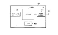
- FIG. 5 is a block diagram of the AP 400. As shown in FIG. 5, the AP 400 includes an antenna 401, a WLAN transceiver 410, a network interface 420, a memory 430, and a processor 440.
- the antenna 401 and the WLAN transceiver 410 are used for transmitting and receiving WLAN radio signals.
- the WLAN transceiver 410 converts the baseband signal output from the processor 440 into a WLAN radio signal and transmits it from the antenna 401. Also, the WLAN transceiver 410 converts the WLAN radio signal received by the antenna 401 into a baseband signal and outputs it to the processor 440.
- the network interface 420 is connected to the EPC 20 via a router or the like.
- the network interface 420 is used for communication with the eNB 200 via the EPC 20.
- the memory 430 stores a program executed by the processor 440 and information used for processing by the processor 340.
- the processor 440 includes a baseband processor that performs modulation / demodulation and encoding / decoding of the baseband signal, and a CPU that executes programs stored in the memory 430 and performs various processes.
- the processor 440 executes various processes and various communication protocols described later.
- the memory 430 may be integrated with the processor 440, and this set (that is, a chip set) may be used as a processor constituting the control unit.
- FIG. 6 is a protocol stack diagram of a radio interface in the cellular communication system. As shown in FIG. 6, the radio interface protocol is divided into layers 1 to 3 of the OSI reference model, and layer 1 is a physical (PHY) layer. Layer 2 includes a MAC (Media Access Control) layer, an RLC (Radio Link Control) layer, and a PDCP (Packet Data Convergence Protocol) layer. Layer 3 includes an RRC (Radio Resource Control) layer.
- PHY Physical
- Layer 2 includes a MAC (Media Access Control) layer, an RLC (Radio Link Control) layer, and a PDCP (Packet Data Convergence Protocol) layer.
- Layer 3 includes an RRC (Radio Resource Control) layer.
- RRC Radio Resource Control
- the physical layer performs encoding / decoding, modulation / demodulation, antenna mapping / demapping, and resource mapping / demapping. Data is transmitted between the physical layer of the UE 100 and the physical layer of the eNB 200 via a physical channel.
- the MAC layer performs data priority control, retransmission processing by hybrid ARQ (HARQ), and the like. Data is transmitted via the transport channel between the MAC layer of the UE 100 and the MAC layer of the eNB 200.
- the MAC layer of the eNB 200 includes a uplink / downlink transport format (transport block size, modulation / coding scheme, and the like) and a scheduler that selects allocated resource blocks.
- the RLC layer transmits data to the RLC layer on the receiving side using the functions of the MAC layer and the physical layer. Data is transmitted between the RLC layer of the UE 100 and the RLC layer of the eNB 200 via a logical channel.
- the PDCP layer performs header compression / decompression and encryption / decryption.
- the RRC layer is defined only in the control plane. Control messages (RRC messages) for various settings are transmitted between the RRC layer of the UE 100 and the RRC layer of the eNB 200.
- the RRC layer controls the logical channel, the transport channel, and the physical channel according to establishment, re-establishment, and release of the radio bearer.
- RRC connection When there is a connection (RRC connection) between the RRC of the UE 100 and the RRC of the eNB 200, the UE 100 is in a connected state (RRC connected state). Otherwise, the UE 100 is in an idle state (RRC idle state).
- the NAS (Non-Access Stratum) layer located above the RRC layer performs session management and mobility management.
- FIG. 7 is a configuration diagram of a radio frame used in the LTE system.
- the LTE system uses OFDMA (Orthogonal Frequency Division Multiplexing Access) for the downlink and SC-FDMA (Single Carrier Division Multiple Access) for the uplink.
- OFDMA Orthogonal Frequency Division Multiplexing Access
- SC-FDMA Single Carrier Division Multiple Access
- the radio frame is composed of ten subframes arranged in the time direction, and each subframe is composed of two slots arranged in the time direction.
- the length of each subframe is 1 ms, and the length of each slot is 0.5 ms.
- Each subframe includes a plurality of resource blocks (RB) in the frequency direction and includes a plurality of symbols in the time direction.
- a guard interval called a cyclic prefix (CP) is provided at the head of each symbol.
- the resource block includes a plurality of subcarriers in the frequency direction.
- a radio resource unit composed of one subcarrier and one symbol is called a resource element (RE).
- RE resource element
- frequency resources can be specified by resource blocks, and time resources can be specified by subframes (or slots).
- the UE 100 has a collocated AP list (co-located AP list).
- UE100 and eNB200 share a collocated AP list.
- the collocated AP list includes a cell ID of a small cell managed by the HeNB 300 that is a side-by-side type arranged at the same location as the AP 400, and location information of the HeNB 300.
- the UE 100 obtains a collocated AP list from eNB 200. For example, the UE 100 receives the collocated AP list from the eNB 200 at the time of establishing a connection, executing a handover, or changing the paging area.
- the eNB 200 may transmit the collocated AP list to the UE 100 based on capability information indicating that the UE 100 supports both cellular communication and WLAN communication methods.
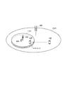
- FIG. 8 is a diagram illustrating a positional relationship between the UE 100, the eNB 200, the HeNB 300, and the AP 400.
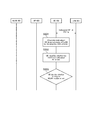
- FIG. 9 is a sequence diagram for explaining an operation according to the first embodiment.
- the UE 100 is located in a large cell managed by the eNB 200. Moreover, HeNB300 and AP400 are arrange
- the eNB 200 and the HeNB 300 operate in the same frequency band. Moreover, in this embodiment, UE100 will move to the direction of HeNB300, and description is advanced on the assumption that it enters into the coverage of a small cell (and the coverage of AP400). Therefore, the UE 100 has not found the AP 400.
- the WLAN transceiver 112 of the UE 100 is in an off state.
- the UE 100 shares the collocated AP list with the eNB 200. That is, the UE 100 has a collocated AP list.
- step S101 the HeNB 300 broadcasts a reference signal including a cell ID (Cell ID).
- Cell ID a cell ID
- the UE 100 receives the reference signal. Thereby, UE100 detects that it exists near HeNB300.
- step S102 the UE 100 specifies whether or not the HeNB 300 that has transmitted the reference signal is a side-by-side type. Specifically, the UE 100 confirms whether the cell ID included in the collocated AP list matches the cell ID included in the reference signal.
- the UE 100 specifies that the HeNB 300 is a side-by-side type. That is, the UE 100 recognizes that the HeNB 300 is a side-by-side type.
- the UE 100 specifies that the HeNB 300 is not the co-located type. That is, the UE 100 recognizes that the HeNB 300 is not a side-by-side type.
- step S103 the UE 100 determines whether or not to switch the WLAN transceiver 112 (WLAN module) to the on state.
- the UE100 switches WLAN transceiver 112 from an OFF state to an ON state, when HeNB300 is a coexisting type.
- the HeNB 300 is not a side-by-side type, the UE 100 maintains the WLAN transceiver 112 in an off state.
- the UE 100 switches the WLAN transceiver 112 to the on state to turn on the scan function and starts a scan for discovering the AP 400.
- FIG. 10 is a sequence diagram for explaining an operation according to the modification of the first embodiment.
- the eNB 200 and the HeNB 300 are operating in different frequency bands. Therefore, UE100 cannot receive the reference signal from HeNB300.
- the UE 100 has a white list (CSG white list) including the location information of the CSG cell to which the UE 100 has access rights and the cell ID of the CSG cell.
- CSG white list including the location information of the CSG cell to which the UE 100 has access rights and the cell ID of the CSG cell.
- the UE 100 moves in the direction of the HeNB 300 and proceeds with the description on the assumption that it enters the small cell coverage (and the AP coverage). Other conditions are the same as those in the first embodiment.
- the UE 100 shares the collocated AP list with the eNB 200.
- step S201 the UE 100 detects proximity to the HeNB 300 based on the white list (Proximity Estimate). Thereby, UE100 detects that it exists near HeNB300.
- step S202 the UE 100 confirms whether the cell ID included in the collocated AP list matches the cell ID of the CSG cell included in the white list.
- the UE 100 specifies that the HeNB 300 is a side-by-side type. That is, the UE 100 recognizes that the HeNB 300 is a side-by-side type.
- the UE 100 specifies that the HeNB 300 is not a co-located type. That is, the UE 100 recognizes that the HeNB 300 is not a side-by-side type.
- Step S203 corresponds to step S103 in FIG.
- the UE 100 detects that the UE 100 exists near the HeNB 300. Further, the UE 100 starts scanning for discovering the AP 400 when the AP 400 has not been discovered and when the UE 100 recognizes that the HeNB 300 is a side-by-side type. Thereby, when AP400 exists near UE100 located near HeNB300, since scanning can be started, AP400 can be discovered efficiently.
- the UE 100 recognizes that the HeNB 300 is a side-by-side type based on the collocated AP list. Thereby, UE100 can discover AP400 efficiently even when it is a case where it is a case where it is not connected with eNB200.
- the UE 100 detects that the UE 100 is present near the HeNB 300 by receiving the cell ID from the HeNB 300. Thereby, UE100 can detect that it exists near HeNB300 only by receiving the reference signal containing cell ID of HeNB300.
- the UE 100 when the eNB 200 and the HeNB 300 are operated in different frequency bands, the UE 100 detects that the UE 100 is present near the HeNB 300 based on the position information included in the white list. Thereby, even if eNB200 and HeNB300 are operate
- the UE 100 acquires a collocated AP list from the eNB 200. Thereby, UE100 can discover AP400 efficiently even when it is a case where it is a case where it is not connected with eNB200.
- FIG. 11 is a sequence diagram for explaining an operation according to the second embodiment.
- the UE 100 determines whether or not the HeNB 300 is a side-by-side type using the collocated AP list.
- the eNB 200 determines whether or not the HeNB 300 is a side-by-side type using the collocated AP list. Therefore, the eNB 200 has a collocated AP list, and the UE 100 does not have a collocated AP list.
- the eNB 200 and the HeNB 300 operate in the same frequency band. Further, in this embodiment, the UE 100 moves in the direction of the HeNB 300 and proceeds with the description on the assumption that the UE 100 enters small cell coverage (and AP coverage). Other conditions are the same as those in the first embodiment.
- step S301 the HeNB 300 broadcasts a reference signal including a cell ID (Cell ID).
- Cell ID a cell ID
- the UE 100 receives the reference signal. Thereby, UE100 detects that it exists near HeNB300.
- step S302 the UE 100 transmits a measurement report (Measurement Report) of received power of the reference signal to the eNB 200.
- the eNB 200 receives the measurement report.
- UE100 notifies eNB200 that UE100 exists near HeNB300 by a measurement report.
- the measurement report includes the cell ID of HeNB 300 included in the reference signal.
- step S303 the eNB 200 determines whether or not the cell ID included in the measurement report matches the cell ID of the collocated AP list. That is, eNB200 specifies whether HeNB300 which transmitted the reference signal is a coexistence type.
- step S304 when the cell ID included in the measurement report matches the cell ID of the collocated AP list (in the case of Yes), the eNB 200 notifies the UE 100 that the HeNB 300 is a co-located type. In addition, the eNB 200 notifies the identifier (for example, SSID (Service Set Identifier) or BSSID (Basic Service Set Identifier)) of the AP 400 disposed in the same place as the HeNB 300.
- SSID Service Set Identifier
- BSSID Basic Service Set Identifier
- the eNB 200 ends the process.
- step S305 the UE 100 specifies that the HeNB 300 is the side-by-side type by notifying that the HeNB 300 is the side-by-side type from the eNB 200.
- Step S306 corresponds to step S103 in FIG.
- the UE 100 may perform scanning based on the identifier of the AP 400 when the scanning function is switched to the on state.
- FIG. 12 is a sequence diagram for explaining the operation according to the modified example of the second embodiment.
- the eNB 200 and the HeNB 300 operate in different frequency bands as in the modification according to the first embodiment. Therefore, UE100 cannot receive the reference signal from HeNB300. Further, in this embodiment, the UE 100 moves in the direction of the HeNB 300 and proceeds with the description on the assumption that the UE 100 enters small cell coverage (and AP coverage). Other conditions are the same as those in the second embodiment.
- Step S401 in FIG. 12 corresponds to step S201 in FIG.
- step S402 the UE 100 transmits, to the eNB 200, a proximity notification (Proximity Indication) indicating that the UE 100 is near the CSG cell.
- the eNB 200 receives the proximity notification.
- the proximity notification includes the cell ID of the CSG cell.
- step S403 the eNB 200 determines whether or not the cell ID included in the proximity notification matches the cell ID of the collocated AP list. That is, eNB200 specifies whether HeNB300 existing in the vicinity of UE100 is a side-by-side type.
- step S404 when the cell ID included in the proximity notification matches the cell ID of the collocated AP list, the eNB 200 performs collocation notification (Collation Indication) indicating that the HeNB 300 is a co-located type.
- the UE 100 receives the collocation notification.
- the eNB 200 transmits a reconfiguration notification including a collocation notification.
- the reconfiguration notification includes measurement settings (Measurement Config.).
- the eNB 200 may transmit a collocation notification and a reconfiguration notification separately.
- the eNB 200 does not transmit the collocation notification.
- step S405 the UE 100 specifies that the HeNB 300 is a side-by-side type based on the collocation notification.
- Step S406 corresponds to step S103 in FIG.
- the eNB 200 notifies the UE 100 that the HeNB 300 is a side-by-side type. Thereby, since UE100 does not need to perform a process in order to confirm whether HeNB300 is a coexistence type based on the collocated AP list, the processing load of UE100 can be reduced.
- the UE 100 when the eNB 200 and the HeNB 300 are operated in the same frequency band, the UE 100 notifies the eNB 200 that it exists near the HeNB 300 by a measurement report of received power from the HeNB 300. Further, when the eNB 200 and the HeNB 300 are operated in different frequency bands, the UE 100 notifies the eNB 200 that the eNB 200 exists near the HeNB 300 by a proximity notification. Thereby, since UE100 does not need to perform the new notification for notifying that it exists near HeNB300, the processing load of UE100 can be reduced.
- eNB200 specified whether HeNB300 was a coexistence type, it is not restricted to this.
- the host device (e.g., MME) of the eNB 200 may specify whether or not the HeNB 300 is a side-by-side type. In this case, the host device of the eNB 200 has a collocated AP list.
- eNB200 transmitted the collocation notification to UE100 with the reset notification, it is not restricted to this.
- the eNB 200 may transmit the identifier of the AP 400 to the UE 100 instead of the collocation notification.
- the measurement trigger Measurement Trigger
- the UE 100 can turn on the scan function and start a scan for finding the identifier of the transmitted AP 400.
- scanning is started by switching the WLAN transceiver 112 from the off state to the on state.
- the present invention is not limited to this.
- the scan function may be switched to an on state. Thereby, UE100 starts a scan.
- the scan function is on but the scan is stopped (for example, a scan function in which a mode for periodically scanning or a mode for starting a scan based on a specific event is selected is on.
- the UE 100 may restart (start) the scan by using the recognition that the HeNB 300 is the side-by-side type as a trigger.
- the HeNB 300 is described as an example of the small cell base station, but is not limited thereto.
- the small cell base station may be a femto cell or a pico cell that manages a small cell.
- the UE 100 performs the processing of the above-described embodiment based on the received reference signal. May be executed.
- the HeNB 300 may notify the UE by broadcast or unicast that the local station is a co-located type. Thereby, UE100 recognizes that HeNB300 is a side-by-side type. Thereby, since UE100 does not need to perform a process in order to confirm whether HeNB300 is a coexistence type based on the collocated AP list, the processing load of UE100 can be reduced.
- the eNB 200 when the eNB 200 is directly connected to the AP 400, the eNB 200 transmits information specifying a channel for performing a scan for the AP 100 to find the AP 400, together with a notification that the local station is a co-located type. Good. Thereby, UE100 can discover AP efficiently by scanning based on the information which designates a channel.
- the eNB 200 may transmit a measurement setting (Measurement Config.) To the UE 100 so that a measurement report (Measurement Report) is performed only when a small cell existing in the collocated AP list is recognized.
- the eNB 200 can notify the UE 100 of the identifier of the AP 400 as soon as the measurement report is received from the UE 100.
- the collocated AP list may include information indicating an identifier of the AP 400 arranged at the same location as the HeNB 300 that is the side-by-side type, in addition to the cell ID of the small cell.
- the UE 100 may perform scanning based on the identifier of the AP 400 corresponding to the recognized HeNB 300.
- the LTE system is described as an example of the cellular communication system.
- the present invention is not limited to the LTE system, and the present invention may be applied to a system other than the LTE system.
- a user terminal having a cellular communication unit and a wireless LAN communication unit can efficiently find an access point, which is useful in the mobile communication field. is there.
Landscapes
- Engineering & Computer Science (AREA)
- Computer Networks & Wireless Communication (AREA)
- Signal Processing (AREA)
- Computer Security & Cryptography (AREA)
- Mobile Radio Communication Systems (AREA)
- Telephonic Communication Services (AREA)
Abstract
This communication control method is a method for linking a cellular communication system with a wireless LAN system. The communication control method comprises: a detection step in which a user terminal having a cellular communication unit and a wireless LAN communication unit detects that the user terminal exists near a small cell base station; a recognition step in which the user terminal recognizes that the small cell base station is of a collocation type positioned at the same location as a wireless LAN access point; and a scan starting step in which the user terminal starts scanning to discover the wireless LAN access point when the user terminal recognizes that the small cell base station is of the collocation type, and when the user terminal has not discovered the wireless LAN access point.
Description
本発明は、セルラ通信システムを無線LANシステムと連携させるための通信制御方法、ユーザ端末、及び、プロセッサに関する。
The present invention relates to a communication control method, a user terminal, and a processor for linking a cellular communication system with a wireless LAN system.
近年、セルラ通信部及び無線LAN通信部を有するユーザ端末(いわゆる、デュアル端末)の普及が進んでいる。また、セルラ通信システムのオペレータにより管理される無線LANアクセスポイント(以下、「アクセスポイント」と称する)が増加している。
In recent years, user terminals (so-called dual terminals) having a cellular communication unit and a wireless LAN communication unit are becoming popular. In addition, wireless LAN access points (hereinafter referred to as “access points”) managed by operators of cellular communication systems are increasing.
そこで、セルラ通信システムの標準化プロジェクトである3GPP(3rd Generation Partnership Project)では、セルラ通信システムと無線LANシステムとの連携を強化できる技術が検討される予定である(非特許文献1参照)。
Therefore, in 3GPP (3rd Generation Partnership Project), which is a standardization project for cellular communication systems, a technology that can strengthen the cooperation between the cellular communication system and the wireless LAN system is planned to be studied (see Non-Patent Document 1).
ところで、ユーザ端末は、無線LANシステムにおけるデータ通信(以下、「無線LAN通信」と称する)を行う場合、アクセスポイントを発見するためにスキャンを行う。スキャンによって、アクセスポイントを発見したユーザ端末は、アクセスポイントと接続することによって、無線LAN通信を行う。
By the way, when performing data communication (hereinafter referred to as “wireless LAN communication”) in the wireless LAN system, the user terminal performs scanning in order to find an access point. A user terminal that has found an access point by scanning performs wireless LAN communication by connecting to the access point.
しかしながら、無線LAN通信を望むユーザ端末は、アクセスポイントを発見できない場合、スキャンをし続けなければならず、無駄なスキャンが行われるという問題がある。
However, if a user terminal that desires wireless LAN communication cannot find an access point, it must continue scanning and there is a problem that useless scanning is performed.
そこで、本発明は、セルラ通信部及び無線LAN通信部を有するユーザ端末が、効率よくアクセスポイントを発見可能な通信制御方法、ユーザ端末、及び、プロセッサを提供する。
Therefore, the present invention provides a communication control method, a user terminal, and a processor that enable a user terminal having a cellular communication unit and a wireless LAN communication unit to efficiently find an access point.
一実施形態によれば、セルラ通信システムを無線LANシステムと連携させるための通信制御方法は、セルラ通信部及び無線LAN通信部を有するユーザ端末が、小セル基地局の近くに存在することを検知する検知ステップと、前記ユーザ端末が、前記小セル基地局が無線LANアクセスポイントと同じ場所に配置された併設タイプであることを認識する認識ステップと、前記ユーザ端末が、前記小セル基地局が前記併設タイプであることを認識した場合で、且つ、前記無線LANアクセスポイントを発見していない場合に、前記無線LANアクセスポイントを発見するためのスキャンを開始するスキャン開始ステップと、を有する。
According to one embodiment, a communication control method for linking a cellular communication system with a wireless LAN system detects that a user terminal having a cellular communication unit and a wireless LAN communication unit exists near a small cell base station. Detecting step, recognizing that the user terminal is a co-located type in which the small cell base station is located at the same location as the wireless LAN access point, and the user terminal that the small cell base station And a scan start step of starting a scan for finding the wireless LAN access point when the wireless LAN access point is not found when the wireless LAN access point is recognized.
本発明に係る通信制御方法、ユーザ端末、及び、プロセッサは、セルラ通信部及び無線LAN通信部を有するユーザ端末が、効率よくアクセスポイントを発見可能である。
The communication control method, user terminal, and processor according to the present invention enable a user terminal having a cellular communication unit and a wireless LAN communication unit to efficiently discover an access point.
[実施形態の概要]
第1実施形態及び第2実施形態に係る通信制御方法は、セルラ通信システムを無線LANシステムと連携させるための通信制御方法である。当該通信制御方法は、セルラ通信部及び無線LAN通信部を有するユーザ端末が、小セル基地局の近くに存在することを検知する検知ステップと、前記ユーザ端末が、前記小セル基地局が無線LANアクセスポイントと同じ場所に配置された併設タイプであることを認識する認識ステップと、前記ユーザ端末が、前記小セル基地局が前記併設タイプであることを認識した場合で、且つ、前記無線LANアクセスポイントを発見していない場合に、前記無線LANアクセスポイントを発見するためのスキャンを開始するスキャン開始ステップと、を有する。 [Outline of Embodiment]
The communication control method according to the first embodiment and the second embodiment is a communication control method for linking a cellular communication system with a wireless LAN system. The communication control method includes a detection step of detecting that a user terminal having a cellular communication unit and a wireless LAN communication unit is present near a small cell base station, and the user terminal is configured such that the small cell base station is a wireless LAN. A recognition step for recognizing that it is a co-located type arranged in the same place as the access point, and a case where the user terminal recognizes that the small cell base station is the co-located type, and the wireless LAN access A scan start step for starting a scan for finding the wireless LAN access point when no point is found.
第1実施形態に係る通信制御方法では、前記認識ステップにおいて、前記ユーザ端末は、前記併設タイプである小セル基地局に関する併設リストに基づいて、前記小セル基地局が前記併設タイプであることを認識する。
In the communication control method according to the first embodiment, in the recognition step, the user terminal determines that the small cell base station is the co-located type based on a co-located list related to the small cell base station that is the co-located type. recognize.
第1実施形態に係る通信制御方法では、前記検知ステップにおいて、前記ユーザ端末は、前記小セル基地局からセル識別子を受信することによって、前記小セル基地局の近くに存在することを検知し、前記認識ステップにおいて、前記ユーザ端末は、前記セル識別子と、前記併設リストに含まれるセル識別子とが一致した場合に、前記小セル基地局が、前記併設タイプであることを認識する。
In the communication control method according to the first embodiment, in the detection step, the user terminal detects that the user terminal is present near the small cell base station by receiving a cell identifier from the small cell base station, In the recognizing step, the user terminal recognizes that the small cell base station is of the co-located type when the cell identifier matches the cell identifier included in the co-located list.
第1実施形態に係る通信制御方法では、前記検知ステップにおいて、前記ユーザ端末は、自身がアクセス権を有する特定セルに関するホワイトリストに含まれる位置情報に基づいて、前記小セル基地局の近くに存在することを検知し、前記認識ステップにおいて、前記ユーザ端末は、前記ホワイトリストに含まれるセル識別子と、前記併設リストに含まれるセル識別子とが一致した場合に、前記小セル基地局が前記併設タイプであることを認識する。
In the communication control method according to the first embodiment, in the detection step, the user terminal is present near the small cell base station based on location information included in a white list related to a specific cell to which the user terminal has access rights. In the recognition step, when the cell identifier included in the white list and the cell identifier included in the side-by-side list match, Recognize that.
第1実施形態に係る通信制御方法は、前記ユーザ端末が、前記小セル基地局が管理する小セルよりも大きなセルを管理する基地局から前記併設リストを取得する取得ステップを、さらに有する。
The communication control method according to the first embodiment further includes an acquisition step in which the user terminal acquires the side-by-side list from a base station that manages a larger cell than a small cell managed by the small cell base station.
第2実施形態に係る通信制御方法は、前記ユーザ端末が、前記小セル基地局の近くに存在することを検知した場合に、前記小セル基地局の近くに存在することを、前記小セル基地局が管理する小セルよりも大きなセルを管理する基地局に通知するユーザ通知ステップと、前記基地局が、前記ユーザ通知ステップにおける通知に基づいて、前記ユーザ端末の近くに存在する前記小セル基地局が前記併設タイプであるか否かを判定する判定ステップと、前記基地局が、前記判定ステップにおいて判定した前記小セル基地局が前記併設タイプである旨を前記ユーザ端末に通知する基地局通知ステップと、をさらに有し、前記認識ステップにおいて、前記ユーザ端末は、前記基地局通知ステップにおける通知に基づいて、前記小セル基地局が前記併設タイプであることを認識する。
When the communication control method according to the second embodiment detects that the user terminal is present near the small cell base station, the communication control method indicates that the user terminal is present near the small cell base station. A user notification step of notifying a base station that manages a cell larger than a small cell managed by the station, and the base station is located near the user terminal based on the notification in the user notification step A determination step of determining whether or not a station is the type of the station; and a base station notification that notifies the user terminal that the small cell base station determined in the determination step is the type of the station And in the recognizing step, the user terminal determines that the small cell base station is based on the notification in the base station notifying step. It recognizes that it is a type.
第2実施形態に係る通信制御方法では、前記検知ステップにおいて、前記ユーザ端末は、前記小セル基地局からセル識別子を受信することによって、前記小セル基地局の近くに存在することを検知し、前記ユーザ通知ステップにおいて、前記ユーザ端末は、前記小セル基地局からの受信電力の測定報告によって、前記小セル基地局の近くに存在する旨を前記基地局に通知する。
In the communication control method according to the second embodiment, in the detection step, the user terminal detects that the user terminal is present near the small cell base station by receiving a cell identifier from the small cell base station, In the user notification step, the user terminal notifies the base station that the user terminal is located near the small cell base station by a measurement report of received power from the small cell base station.
第2実施形態に係る通信制御方法では、前記検知ステップにおいて、前記ユーザ端末は、自身がアクセス権を有する特定セルに関するホワイトリストに含まれる位置情報に基づいて、前記小セル基地局の近くに存在することを検知し、前記ユーザ通知ステップにおいて、前記ユーザ端末は、前記特定セルの近くにいることを示す近傍通知によって、前記小セル基地局の近くに存在する旨を前記基地局に通知する。
In the communication control method according to the second embodiment, in the detection step, the user terminal is present near the small cell base station based on location information included in a white list related to a specific cell to which the user terminal has access rights. In the user notification step, the user terminal notifies the base station that it is near the small cell base station by a proximity notification indicating that the user terminal is near the specific cell.
その他実施形態に係る通信制御方法は、前記小セル基地局が、自局が前記併設タイプである旨を前記ユーザ端末に通知する通知ステップをさらに有し、前記認識ステップにおいて、前記ユーザ端末は、前記小セル基地局と接続している場合で、且つ、前記通知ステップにおける通知を受信した場合に、前記小セル基地局が前記併設タイプであると認識する。
The communication control method according to another embodiment further includes a notification step in which the small cell base station notifies the user terminal that the local station is the co-located type, and in the recognition step, the user terminal When it is connected to the small cell base station and the notification in the notification step is received, the small cell base station recognizes that the small cell base station is the side-by-side type.
その他実施形態に係る通信制御方法では、前記通知ステップにおいて、前記小セル基地局は、前記無線LANアクセスポイントと直接的に接続されている場合に、前記通知ステップにおける通知と共に、前記スキャンを行うチャンネルを指定する情報を送信する。
In the communication control method according to another embodiment, in the notification step, when the small cell base station is directly connected to the wireless LAN access point, the channel that performs the scan together with the notification in the notification step Send information specifying.
実施形態に係るユーザ端末は、セルラ通信部及び無線LAN通信部を有するユーザ端末であって、小セル基地局の近くに存在することを検知する制御を行う制御部を備え、前記制御部は、前記小セル基地局が、無線LANアクセスポイントと同じ場所に配置された併設タイプであることを認識する制御を行い、前記制御部は、前記小セル基地局が前記併設タイプであることを認識した場合で、且つ、前記無線LANアクセスポイントを発見していない場合に、前記無線LANアクセスポイントを発見するためのスキャンを開始する制御を行う。
The user terminal according to the embodiment is a user terminal having a cellular communication unit and a wireless LAN communication unit, and includes a control unit that performs control to detect the presence near a small cell base station, and the control unit includes: The small cell base station performs control for recognizing that the small cell base station is a coexisting type disposed at the same location as the wireless LAN access point, and the control unit has recognized that the small cell base station is the coexisting type In this case, when the wireless LAN access point is not found, a control for starting a scan for finding the wireless LAN access point is performed.
実施形態に係るプロセッサは、セルラ通信部及び無線LAN通信部を有するユーザ端末に備えられるプロセッサであって、小セル基地局の近くに存在することを検知する処理を実行し、前記小セル基地局が、無線LANアクセスポイントと同じ場所に配置された併設タイプであることを認識する処理を実行し、前記小セル基地局が前記併設タイプであることが認識された場合で、且つ、前記無線LANアクセスポイントを発見していない場合に、前記無線LANアクセスポイントを発見するためのスキャンを開始する処理を実行する。
The processor which concerns on embodiment is a processor with which the user terminal which has a cellular communication part and a wireless LAN communication part is provided, Comprising: The process which detects existing near a small cell base station is performed, The said small cell base station Executes a process of recognizing that the small cell base station is the side-by-side type, and performs processing for recognizing that the side-by-side type is located at the same location as the wireless LAN access point, and the wireless LAN When no access point is found, a process for starting a scan for finding the wireless LAN access point is executed.
なお、本明細書において、無線端末が、無線LANアクセスポイントを発見していないケースは、無線LAN通信部がオフ状態であるため、無線LANアクセスポイントが発見されていないケースと、無線LAN通信部がオン状態であるが、スキャンを停止しているため、無線LANアクセスポイントが発見されていないケースと、を含む。
In the present specification, the case where the wireless terminal has not found the wireless LAN access point is the case where the wireless LAN access point has not been found since the wireless LAN communication unit is in the off state, and the wireless LAN communication unit Includes a case where the wireless LAN access point is not found because scanning is stopped.
以下、図面を参照して、3GPP規格に準拠して構成されるセルラ通信システム(LTEシステム)を無線LAN(WLAN)システムと連携させる場合の各実施形態を説明する。
Hereinafter, with reference to the drawings, each embodiment in the case of linking a cellular communication system (LTE system) configured in accordance with the 3GPP standard with a wireless LAN (WLAN) system will be described.
[第1実施形態]
(システム構成)
図1は、第1実施形態に係るシステム構成図である。図1に示すように、セルラ通信システムは、複数のUE(User Equipment)100と、E-UTRAN(Evolved Universal Terrestrial Radio Access Network)10と、EPC(Evolved Packet Core)20と、を含む。E-UTRAN10は、無線アクセスネットワークに相当する。EPC20は、コアネットワークに相当する。 [First Embodiment]
(System configuration)
FIG. 1 is a system configuration diagram according to the first embodiment. As shown in FIG. 1, the cellular communication system includes a plurality of UEs (User Equipment) 100, an E-UTRAN (Evolved Universal Terrestrial Radio Access Network) 10, and an EPC (Evolved Packet Core) 20. TheE-UTRAN 10 corresponds to a radio access network. The EPC 20 corresponds to a core network.
(システム構成)
図1は、第1実施形態に係るシステム構成図である。図1に示すように、セルラ通信システムは、複数のUE(User Equipment)100と、E-UTRAN(Evolved Universal Terrestrial Radio Access Network)10と、EPC(Evolved Packet Core)20と、を含む。E-UTRAN10は、無線アクセスネットワークに相当する。EPC20は、コアネットワークに相当する。 [First Embodiment]
(System configuration)
FIG. 1 is a system configuration diagram according to the first embodiment. As shown in FIG. 1, the cellular communication system includes a plurality of UEs (User Equipment) 100, an E-UTRAN (Evolved Universal Terrestrial Radio Access Network) 10, and an EPC (Evolved Packet Core) 20. The
UE100は、移動型の無線通信装置であり、接続を確立したセルとの無線通信を行う。UE100はユーザ端末に相当する。UE100は、セルラ通信及びWLAN通信の両通信方式をサポートする端末(デュアル端末)である。
The UE 100 is a mobile radio communication device, and performs radio communication with a cell that has established a connection. UE100 is corresponded to a user terminal. The UE 100 is a terminal (dual terminal) that supports both cellular communication and WLAN communication methods.
E-UTRAN10は、eNB200(evolved Node-B)と、HeNB300(Home evolved Node-B)とを含む。eNB200はセルラ基地局に相当する。
The E-UTRAN 10 includes an eNB 200 (evolved Node-B) and a HeNB 300 (Home evolved Node-B). The eNB 200 corresponds to a cellular base station.
eNB200は、1又は複数のセル(大セル)を管理しており、自セルとの接続(RRCコネクション)を確立したUE100との無線通信を行う。なお、「セル」は、無線通信エリアの最小単位を示す用語として使用される他に、UE100との無線通信を行う機能を示す用語としても使用される。また、eNB200は、例えば、無線リソース管理(RRM)機能と、ユーザデータのルーティング機能と、モビリティ制御及びスケジューリングのための測定制御機能と、を有する。
The eNB 200 manages one or a plurality of cells (large cells) and performs radio communication with the UE 100 that has established a connection (RRC connection) with the own cell. Note that “cell” is used as a term indicating a minimum unit of a radio communication area, and is also used as a term indicating a function of performing radio communication with the UE 100. The eNB 200 has, for example, a radio resource management (RRM) function, a user data routing function, and a measurement control function for mobility control and scheduling.
eNB200は、X2インターフェイスを介して相互に接続される。また、eNB200は、S1インターフェイスを介して、EPC20に含まれるMME/S-GW500と接続される。
The eNB 200 is connected to each other via the X2 interface. The eNB 200 is connected to the MME / S-GW 500 included in the EPC 20 via the S1 interface.
HeNB300は、大セルよりもカバー範囲が狭い特定セル(小セル)を管理する。HeNB300は、特定セルとの接続(RRCコネクション)を確立したUE100との無線通信を行う。
The HeNB 300 manages a specific cell (small cell) whose coverage is narrower than that of the large cell. HeNB300 performs radio | wireless communication with UE100 which established the connection (RRC connection) with a specific cell.
特定セルは、設定されるアクセスモードに応じて、「CSGセル」、「ハイブリッドセル」、又は「オープンセル」と称される。
The specific cell is referred to as a “CSG cell”, a “hybrid cell”, or an “open cell” depending on the set access mode.
CSGセルは、アクセス権を有するUE100(「メンバーUE」と称される)のみがアクセス可能なセルであり、CSG IDをブロードキャストする。UE100は、自身がアクセス権を有するCSGセルのCSG IDのリスト(ホワイトリスト)を保持しており、当該ホワイトリストと、CSGセルがブロードキャストするCSG IDと、に基づいて、アクセス権の有無を判断する。
The CSG cell is a cell that can be accessed only by the UE 100 having the access right (referred to as “member UE”), and broadcasts the CSG ID. The UE 100 maintains a list (white list) of CSG IDs of CSG cells to which the UE 100 has access rights, and determines whether there is access rights based on the white list and the CSG ID broadcast by the CSG cell. To do.
ハイブリッドセルは、メンバーUEが非メンバーUEよりも有利に取り扱われるセルであり、CSG IDに加えて、非メンバーUEにも解放されたセルであることを示す情報をブロードキャストする。UE100は、ホワイトリストと、ハイブリッドセルがブロードキャストするCSG IDと、に基づいて、アクセス権の有無を判断する。
The hybrid cell is a cell in which the member UE is handled more favorably than the non-member UE, and broadcasts information indicating that the cell is a cell released to the non-member UE in addition to the CSG ID. The UE 100 determines whether or not there is an access right based on the white list and the CSG ID broadcast by the hybrid cell.
オープンセルは、メンバーであるか否かを問わずUE100が同等に取り扱われるセルであり、CSG IDをブロードキャストしない。UE100の視点では、オープンセルはセルと同等である。
An open cell is a cell that is handled equally by the UE 100 regardless of whether it is a member, and does not broadcast a CSG ID. From the viewpoint of UE 100, an open cell is equivalent to a cell.
EPC20は、複数のMME(Mobility Management Entity)/S-GW(Serving-Gateway)500を含む。
The EPC 20 includes a plurality of MME (Mobility Management Entity) / S-GW (Serving-Gateway) 500.
MMEは、UE100に対する各種モビリティ制御等を行うネットワークノードであり、制御局に相当する。S-GWは、ユーザデータの転送制御を行うネットワークノードであり、交換局に相当する。MMEは、CSGセルへのアクセス権についてUE100の認証を行う。
The MME is a network node that performs various types of mobility control for the UE 100, and corresponds to a control station. The S-GW is a network node that performs transfer control of user data, and corresponds to an exchange. The MME authenticates the UE 100 with respect to the access right to the CSG cell.
WLANシステムは、WLAN AP(以下、「AP」と称する)400を含む。WLANシステムは、例えばIEEE 802.11諸規格に準拠して構成される。AP400は、セルラ周波数帯とは異なる周波数帯(WLAN周波数帯)でUE100との通信を行う。AP400は、ルータなどを介してEPC20に接続される。
The WLAN system includes a WLAN AP (hereinafter referred to as “AP”) 400. The WLAN system is configured in accordance with, for example, IEEE 802.11 standards. AP 400 communicates with UE 100 in a frequency band (WLAN frequency band) different from the cellular frequency band. The AP 400 is connected to the EPC 20 via a router or the like.
HeNB300とAP400とは、同じ場所に配置(Collocated)されている。従って、HeNB300は、併設タイプである。例えば、併設タイプのHeNB300として、HeNB300とAP400とが、同一の筐体に配置された一体型であってもよい。Collocatedの一形態として、HeNB300及びAP400がオペレータの任意のインターフェイスで直接的に接続されていてもよい。また、HeNB300とAP400とは、制御部を共有してもよい。
The HeNB 300 and the AP 400 are arranged (Collocated) at the same place. Therefore, HeNB300 is a side-by-side type. For example, as the side-by-side type HeNB 300, the HeNB 300 and the AP 400 may be an integrated type arranged in the same casing. As one form of Collated, the HeNB 300 and the AP 400 may be directly connected by an arbitrary interface of the operator. Moreover, HeNB300 and AP400 may share a control part.
次に、UE100、eNB200、HeNB300、及び、AP400の構成を説明する。
Next, configurations of the UE 100, the eNB 200, the HeNB 300, and the AP 400 will be described.
図2は、UE100のブロック図である。図2に示すように、UE100は、アンテナ101及び102と、セルラ送受信機(セルラ通信部)111と、WLAN送受信機(無線LAN通信部)112と、ユーザインターフェイス120と、GNSS(Global Navigation Satellite System)受信機130と、バッテリ140と、メモリ150と、プロセッサ160と、を有する。メモリ150及びプロセッサ160は、制御部を構成する。UE100は、GNSS受信機130を有していなくてもよい。また、メモリ150をプロセッサ160と一体化し、このセット(すなわち、チップセット)を、制御部を構成するプロセッサ160’としてもよい。
FIG. 2 is a block diagram of the UE 100. As shown in FIG. 2, the UE 100 includes antennas 101 and 102, a cellular transceiver (cellular communication unit) 111, a WLAN transceiver (wireless LAN communication unit) 112, a user interface 120, a GNSS (Global Navigation Satellite System). ) The receiver 130, the battery 140, the memory 150, and the processor 160. The memory 150 and the processor 160 constitute a control unit. The UE 100 may not have the GNSS receiver 130. Further, the memory 150 may be integrated with the processor 160, and this set (that is, a chip set) may be used as the processor 160 'that constitutes the control unit.
アンテナ101及びセルラ送受信機111は、セルラ無線信号の送受信に用いられる。セルラ送受信機111は、プロセッサ160が出力するベースバンド信号をセルラ無線信号に変換してアンテナ101から送信する。また、セルラ送受信機111は、アンテナ101が受信するセルラ無線信号をベースバンド信号に変換してプロセッサ160に出力する。
The antenna 101 and the cellular transceiver 111 are used for transmitting and receiving cellular radio signals. The cellular transceiver 111 converts the baseband signal output from the processor 160 into a cellular radio signal and transmits it from the antenna 101. In addition, the cellular transceiver 111 converts a cellular radio signal received by the antenna 101 into a baseband signal and outputs it to the processor 160.
アンテナ102及びWLAN送受信機112は、WLAN無線信号の送受信に用いられる。WLAN送受信機112は、プロセッサ160が出力するベースバンド信号をWLAN無線信号に変換してアンテナ102から送信する。また、WLAN送受信機112は、アンテナ102が受信するWLAN無線信号をベースバンド信号に変換してプロセッサ160に出力する。
The antenna 102 and the WLAN transceiver 112 are used for transmitting and receiving WLAN radio signals. The WLAN transceiver 112 converts the baseband signal output from the processor 160 into a WLAN radio signal and transmits it from the antenna 102. Further, the WLAN transceiver 112 converts the WLAN radio signal received by the antenna 102 into a baseband signal and outputs the baseband signal to the processor 160.
WLAN送受信機112は、AP400を発見するためのスキャンを行う。
The WLAN transceiver 112 performs a scan to find the AP 400.
ユーザインターフェイス120は、UE100を所持するユーザとのインターフェイスであり、例えば、ディスプレイ、マイク、スピーカ、及び各種ボタンなどを含む。ユーザインターフェイス120は、ユーザからの入力を受け付けて、該入力の内容を示す信号をプロセッサ160に出力する。GNSS受信機130は、UE100の地理的な位置を示す位置情報を得るために、GNSS信号を受信して、受信した信号をプロセッサ160に出力する。バッテリ140は、UE100の各ブロックに供給すべき電力を蓄える。
The user interface 120 is an interface with a user who owns the UE 100, and includes, for example, a display, a microphone, a speaker, and various buttons. The user interface 120 receives an input from the user and outputs a signal indicating the content of the input to the processor 160. The GNSS receiver 130 receives a GNSS signal and outputs the received signal to the processor 160 in order to obtain location information indicating the geographical location of the UE 100. The battery 140 stores power to be supplied to each block of the UE 100.
メモリ150は、プロセッサ160によって実行されるプログラムと、プロセッサ160による処理に使用される情報と、を記憶する。プロセッサ160は、ベースバンド信号の変調・復調及び符号化・復号などを行うベースバンドプロセッサと、メモリ150に記憶されるプログラムを実行して各種の処理を行うCPUと、を含む。プロセッサ160は、さらに、音声・映像信号の符号化・復号を行うコーデックを含んでもよい。
The memory 150 stores a program executed by the processor 160 and information used for processing by the processor 160. The processor 160 includes a baseband processor that performs modulation / demodulation and encoding / decoding of a baseband signal, and a CPU that executes programs stored in the memory 150 and performs various processes. The processor 160 may further include a codec that performs encoding / decoding of an audio / video signal.
プロセッサ160は、後述する各種の処理及び各種の通信プロトコルを実行する。具体的には、例えば、プロセッサ160は、WLAN送受信機112にスキャンを行わせる制御を行う。プロセッサ160は、AP400を発見していない場合で、且つ、HeNB300が併設タイプであることを認識した場合に、WLAN送受信機112がスキャンを開始するための制御を行う。
The processor 160 executes various processes and various communication protocols described later. Specifically, for example, the processor 160 performs control to cause the WLAN transceiver 112 to perform scanning. The processor 160 performs control for the WLAN transceiver 112 to start scanning when the AP 400 has not been found and when it is recognized that the HeNB 300 is the side-by-side type.
図3は、eNB200のブロック図である。図3に示すように、eNB200は、アンテナ201と、セルラ送受信機210と、ネットワークインターフェイス220と、メモリ230と、プロセッサ240と、を有する。メモリ230及びプロセッサ240は、制御部を構成する。なお、メモリ230をプロセッサ240と一体化し、このセット(すなわち、チップセット)を、制御部を構成するプロセッサとしてもよい。
FIG. 3 is a block diagram of the eNB 200. As illustrated in FIG. 3, the eNB 200 includes an antenna 201, a cellular transceiver 210, a network interface 220, a memory 230, and a processor 240. The memory 230 and the processor 240 constitute a control unit. Note that the memory 230 may be integrated with the processor 240, and this set (that is, a chip set) may be a processor constituting the control unit.
アンテナ201及びセルラ送受信機210は、セルラ無線信号の送受信に用いられる。セルラ送受信機210は、プロセッサ240が出力するベースバンド信号をセルラ無線信号に変換してアンテナ201から送信する。また、セルラ送受信機210は、アンテナ201が受信するセルラ無線信号をベースバンド信号に変換してプロセッサ240に出力する。
The antenna 201 and the cellular transceiver 210 are used for transmitting and receiving cellular radio signals. The cellular transceiver 210 converts the baseband signal output from the processor 240 into a cellular radio signal and transmits it from the antenna 201. In addition, the cellular transceiver 210 converts a cellular radio signal received by the antenna 201 into a baseband signal and outputs it to the processor 240.
ネットワークインターフェイス220は、X2インターフェイスを介して隣接eNB200又は隣接HeNB300と接続され、S1インターフェイスを介してMME/S-GW500と接続される。また、ネットワークインターフェイス220は、EPC20を介したAP400との通信に使用される。
The network interface 220 is connected to the adjacent eNB 200 or the adjacent HeNB 300 via the X2 interface, and is connected to the MME / S-GW 500 via the S1 interface. The network interface 220 is used for communication with the AP 400 via the EPC 20.
メモリ230は、プロセッサ240によって実行されるプログラムと、プロセッサ240による処理に使用される情報と、を記憶する。プロセッサ240は、ベースバンド信号の変調・復調及び符号化・復号などを行うベースバンドプロセッサと、メモリ230に記憶されるプログラムを実行して各種の処理を行うCPUと、を含む。プロセッサ240は、後述する各種の処理及び各種の通信プロトコルを実行する。
The memory 230 stores a program executed by the processor 240 and information used for processing by the processor 240. The processor 240 includes a baseband processor that performs modulation / demodulation and encoding / decoding of a baseband signal, and a CPU that executes a program stored in the memory 230 and performs various processes. The processor 240 executes various processes and various communication protocols described later.
図4は、HeNB300のブロック図である。図4に示すように、HeNB300は、アンテナ301と、セルラ送受信機310と、ネットワークインターフェイス320と、メモリ330と、プロセッサ340と、を有する。メモリ330及びプロセッサ340は、制御部を構成する。なお、メモリ330をプロセッサ340と一体化し、このセット(すなわち、チップセット)を、制御部を構成するプロセッサとしてもよい。
FIG. 4 is a block diagram of the HeNB 300. As illustrated in FIG. 4, the HeNB 300 includes an antenna 301, a cellular transceiver 310, a network interface 320, a memory 330, and a processor 340. The memory 330 and the processor 340 constitute a control unit. Note that the memory 330 may be integrated with the processor 340, and this set (that is, a chip set) may be a processor constituting the control unit.
アンテナ301及びセルラ送受信機310は、セルラ無線信号の送受信に用いられる。セルラ送受信機310は、プロセッサ340が出力するベースバンド信号をセルラ無線信号に変換してアンテナ301から送信する。また、セルラ送受信機310は、アンテナ301が受信するセルラ無線信号をベースバンド信号に変換してプロセッサ340に出力する。本実施形態において、セルラ送受信機310は、CSGセルを形成する。
The antenna 301 and the cellular transceiver 310 are used for transmitting and receiving cellular radio signals. The cellular transceiver 310 converts the baseband signal output from the processor 340 into a cellular radio signal and transmits it from the antenna 301. In addition, the cellular transceiver 310 converts a cellular radio signal received by the antenna 301 into a baseband signal and outputs it to the processor 340. In this embodiment, the cellular transceiver 310 forms a CSG cell.
ネットワークインターフェイス320は、X2インターフェイスを介して隣接eNB200又は隣接HeNB300と接続され、S1インターフェイスを介してMME/S-GW500と接続される。また、ネットワークインターフェイス320は、EPC20を介したAP400との通信に使用される。
The network interface 320 is connected to the adjacent eNB 200 or the adjacent HeNB 300 via the X2 interface, and is connected to the MME / S-GW 500 via the S1 interface. The network interface 320 is used for communication with the AP 400 via the EPC 20.
メモリ330は、プロセッサ340によって実行されるプログラムと、プロセッサ340による処理に使用される情報と、を記憶する。プロセッサ340は、ベースバンド信号の変調・復調及び符号化・復号などを行うベースバンドプロセッサと、メモリ330に記憶されるプログラムを実行して各種の処理を行うCPUと、を含む。プロセッサ340は、後述する各種の処理及び各種の通信プロトコルを実行する。
The memory 330 stores a program executed by the processor 340 and information used for processing by the processor 340. The processor 340 includes a baseband processor that performs modulation / demodulation and encoding / decoding of the baseband signal, and a CPU that executes programs stored in the memory 330 and performs various processes. The processor 340 executes various processes and various communication protocols described later.
図5は、AP400のブロック図である。図5に示すように、AP400は、アンテナ401と、WLAN送受信機410と、ネットワークインターフェイス420と、メモリ430と、プロセッサ440と、を有する。
FIG. 5 is a block diagram of the AP 400. As shown in FIG. 5, the AP 400 includes an antenna 401, a WLAN transceiver 410, a network interface 420, a memory 430, and a processor 440.
アンテナ401及びWLAN送受信機410は、WLAN無線信号の送受信に用いられる。WLAN送受信機410は、プロセッサ440が出力するベースバンド信号をWLAN無線信号に変換してアンテナ401から送信する。また、WLAN送受信機410は、アンテナ401が受信するWLAN無線信号をベースバンド信号に変換してプロセッサ440に出力する。
The antenna 401 and the WLAN transceiver 410 are used for transmitting and receiving WLAN radio signals. The WLAN transceiver 410 converts the baseband signal output from the processor 440 into a WLAN radio signal and transmits it from the antenna 401. Also, the WLAN transceiver 410 converts the WLAN radio signal received by the antenna 401 into a baseband signal and outputs it to the processor 440.
ネットワークインターフェイス420は、ルータなどを介してEPC20と接続される。また、ネットワークインターフェイス420は、EPC20を介したeNB200との通信に使用される。
The network interface 420 is connected to the EPC 20 via a router or the like. The network interface 420 is used for communication with the eNB 200 via the EPC 20.
メモリ430は、プロセッサ440によって実行されるプログラムと、プロセッサ340による処理に使用される情報と、を記憶する。プロセッサ440は、ベースバンド信号の変調・復調及び符号化・復号などを行うベースバンドプロセッサと、メモリ430に記憶されるプログラムを実行して各種の処理を行うCPUと、を含む。プロセッサ440は、後述する各種の処理及び各種の通信プロトコルを実行する。
The memory 430 stores a program executed by the processor 440 and information used for processing by the processor 340. The processor 440 includes a baseband processor that performs modulation / demodulation and encoding / decoding of the baseband signal, and a CPU that executes programs stored in the memory 430 and performs various processes. The processor 440 executes various processes and various communication protocols described later.
なお、メモリ430をプロセッサ440と一体化し、このセット(すなわち、チップセット)を、制御部を構成するプロセッサとしてもよい。
Note that the memory 430 may be integrated with the processor 440, and this set (that is, a chip set) may be used as a processor constituting the control unit.
図6は、セルラ通信システムにおける無線インターフェイスのプロトコルスタック図である。図6に示すように、無線インターフェイスプロトコルは、OSI参照モデルのレイヤ1乃至レイヤ3に区分されており、レイヤ1は物理(PHY)レイヤである。レイヤ2は、MAC(Media Access Control)レイヤと、RLC(Radio Link Control)レイヤと、PDCP(Packet Data Convergence Protocol)レイヤと、を含む。レイヤ3は、RRC(Radio Resource Control)レイヤを含む。
FIG. 6 is a protocol stack diagram of a radio interface in the cellular communication system. As shown in FIG. 6, the radio interface protocol is divided into layers 1 to 3 of the OSI reference model, and layer 1 is a physical (PHY) layer. Layer 2 includes a MAC (Media Access Control) layer, an RLC (Radio Link Control) layer, and a PDCP (Packet Data Convergence Protocol) layer. Layer 3 includes an RRC (Radio Resource Control) layer.
物理レイヤは、符号化・復号、変調・復調、アンテナマッピング・デマッピング、及びリソースマッピング・デマッピングを行う。UE100の物理レイヤとeNB200の物理レイヤとの間では、物理チャネルを介してデータが伝送される。
The physical layer performs encoding / decoding, modulation / demodulation, antenna mapping / demapping, and resource mapping / demapping. Data is transmitted between the physical layer of the UE 100 and the physical layer of the eNB 200 via a physical channel.
MACレイヤは、データの優先制御、及びハイブリッドARQ(HARQ)による再送処理などを行う。UE100のMACレイヤとeNB200のMACレイヤとの間では、トランスポートチャネルを介してデータが伝送される。eNB200のMACレイヤは、上下リンクのトランスポートフォーマット(トランスポートブロックサイズ、変調・符号化方式など)、及び割当リソースブロックを選択するスケジューラを含む。
The MAC layer performs data priority control, retransmission processing by hybrid ARQ (HARQ), and the like. Data is transmitted via the transport channel between the MAC layer of the UE 100 and the MAC layer of the eNB 200. The MAC layer of the eNB 200 includes a uplink / downlink transport format (transport block size, modulation / coding scheme, and the like) and a scheduler that selects allocated resource blocks.
RLCレイヤは、MACレイヤ及び物理レイヤの機能を利用してデータを受信側のRLCレイヤに伝送する。UE100のRLCレイヤとeNB200のRLCレイヤとの間では、論理チャネルを介してデータが伝送される。
The RLC layer transmits data to the RLC layer on the receiving side using the functions of the MAC layer and the physical layer. Data is transmitted between the RLC layer of the UE 100 and the RLC layer of the eNB 200 via a logical channel.
PDCPレイヤは、ヘッダ圧縮・伸張、及び暗号化・復号化を行う。
The PDCP layer performs header compression / decompression and encryption / decryption.
RRCレイヤは、制御プレーンでのみ定義される。UE100のRRCレイヤとeNB200のRRCレイヤとの間では、各種設定のための制御メッセージ(RRCメッセージ)が伝送される。RRCレイヤは、無線ベアラの確立、再確立及び解放に応じて、論理チャネル、トランスポートチャネル、及び物理チャネルを制御する。UE100のRRCとeNB200のRRCとの間に接続(RRC接続)がある場合、UE100は接続状態(RRC connected state)であり、そうでない場合、UE100はアイドル状態(RRC idle state)である。
The RRC layer is defined only in the control plane. Control messages (RRC messages) for various settings are transmitted between the RRC layer of the UE 100 and the RRC layer of the eNB 200. The RRC layer controls the logical channel, the transport channel, and the physical channel according to establishment, re-establishment, and release of the radio bearer. When there is a connection (RRC connection) between the RRC of the UE 100 and the RRC of the eNB 200, the UE 100 is in a connected state (RRC connected state). Otherwise, the UE 100 is in an idle state (RRC idle state).
RRCレイヤの上位に位置するNAS(Non-Access Stratum)レイヤは、セッション管理及びモビリティ管理などを行う。
The NAS (Non-Access Stratum) layer located above the RRC layer performs session management and mobility management.
図7は、LTEシステムで使用される無線フレームの構成図である。LTEシステムは、下りリンクにはOFDMA(Orthogonal Frequency Division Multiplexing Access)、上りリンクにはSC-FDMA(Single Carrier Frequency Division Multiple Access)がそれぞれ使用される。
FIG. 7 is a configuration diagram of a radio frame used in the LTE system. The LTE system uses OFDMA (Orthogonal Frequency Division Multiplexing Access) for the downlink and SC-FDMA (Single Carrier Division Multiple Access) for the uplink.
図7に示すように、無線フレームは、時間方向に並ぶ10個のサブフレームで構成され、各サブフレームは、時間方向に並ぶ2個のスロットで構成される。各サブフレームの長さは1msであり、各スロットの長さは0.5msである。各サブフレームは、周波数方向に複数個のリソースブロック(RB)を含み、時間方向に複数個のシンボルを含む。各シンボルの先頭には、サイクリックプレフィックス(CP)と呼ばれるガード区間が設けられる。リソースブロックは、周波数方向に複数個のサブキャリアを含む。1つのサブキャリア及び1つのシンボルにより構成される無線リソース単位はリソースエレメント(RE)と称される。
As shown in FIG. 7, the radio frame is composed of ten subframes arranged in the time direction, and each subframe is composed of two slots arranged in the time direction. The length of each subframe is 1 ms, and the length of each slot is 0.5 ms. Each subframe includes a plurality of resource blocks (RB) in the frequency direction and includes a plurality of symbols in the time direction. A guard interval called a cyclic prefix (CP) is provided at the head of each symbol. The resource block includes a plurality of subcarriers in the frequency direction. A radio resource unit composed of one subcarrier and one symbol is called a resource element (RE).
UE100に割り当てられる無線リソースのうち、周波数リソースはリソースブロックにより特定でき、時間リソースはサブフレーム(又はスロット)により特定できる。
Among radio resources allocated to the UE 100, frequency resources can be specified by resource blocks, and time resources can be specified by subframes (or slots).
(コロケーティッドAPリスト)
本実施形態において、UE100は、コロケーティッドAPリスト(collocated AP list;併設リスト)を有する。UE100とeNB200とは、コロケーティッドAPリストを共有する。 (Collocated AP List)
In the present embodiment, theUE 100 has a collocated AP list (co-located AP list). UE100 and eNB200 share a collocated AP list.
本実施形態において、UE100は、コロケーティッドAPリスト(collocated AP list;併設リスト)を有する。UE100とeNB200とは、コロケーティッドAPリストを共有する。 (Collocated AP List)
In the present embodiment, the
コロケーティッドAPリストは、AP400と同じ場所に配置された併設タイプであるHeNB300が管理する小セルのセルIDと、当該HeNB300の位置情報とを含む。
The collocated AP list includes a cell ID of a small cell managed by the HeNB 300 that is a side-by-side type arranged at the same location as the AP 400, and location information of the HeNB 300.
UE100は、コロケーティッドAPリストをeNB200から取得する。例えば、UE100は、コネクションを確立する時、ハンドオーバを実行する時、又は、ページングエリアを変更する時のタイミングで、eNB200からコロケーティッドAPリストを受信する。
UE 100 obtains a collocated AP list from eNB 200. For example, the UE 100 receives the collocated AP list from the eNB 200 at the time of establishing a connection, executing a handover, or changing the paging area.
eNB200は、UE100がセルラ通信及びWLAN通信の両通信方式をサポートすることを示すケーパビリティ情報に基づいて、コロケーティッドAPリストをUE100に送信してもよい。
The eNB 200 may transmit the collocated AP list to the UE 100 based on capability information indicating that the UE 100 supports both cellular communication and WLAN communication methods.
(第1実施形態に係る動作)
次に、第1実施形態に係る動作について、図8及び図9を用いて説明する。図8は、UE100、eNB200、HeNB300、及びAP400の位置関係を示す図である。
図9は、第1実施形態に係る動作を説明するためのシーケンス図である。 (Operation according to the first embodiment)
Next, the operation according to the first embodiment will be described with reference to FIGS. FIG. 8 is a diagram illustrating a positional relationship between theUE 100, the eNB 200, the HeNB 300, and the AP 400.
FIG. 9 is a sequence diagram for explaining an operation according to the first embodiment.
次に、第1実施形態に係る動作について、図8及び図9を用いて説明する。図8は、UE100、eNB200、HeNB300、及びAP400の位置関係を示す図である。
図9は、第1実施形態に係る動作を説明するためのシーケンス図である。 (Operation according to the first embodiment)
Next, the operation according to the first embodiment will be described with reference to FIGS. FIG. 8 is a diagram illustrating a positional relationship between the
FIG. 9 is a sequence diagram for explaining an operation according to the first embodiment.
図8に示すように、UE100は、eNB200が管理する大セルに在圏する。また、HeNB300及びAP400は、同じ場所に配置されている。すなわち、HeNB300は、併設タイプである。HeNB300が管理する小セルのカバレッジとAP400のカバレッジは、少なくとも一部が重複しており、同程度の大きさである。また、小セルのカバレッジとAPのカバレッジとは、大セルのカバレッジに包含されている。
As shown in FIG. 8, the UE 100 is located in a large cell managed by the eNB 200. Moreover, HeNB300 and AP400 are arrange | positioned at the same place. That is, HeNB300 is a side-by-side type. The coverage of the small cell managed by the HeNB 300 and the coverage of the AP 400 are at least partially overlapped and have the same size. The small cell coverage and the AP coverage are included in the large cell coverage.
本実施形態において、eNB200とHeNB300とは、同一の周波数帯で運用している。また、本実施形態において、UE100は、HeNB300の方向へ移動し、小セルのカバレッジ(及びAP400のカバレッジ)に入ると仮定して説明を進める。従って、UE100は、AP400を発見していない。
In this embodiment, the eNB 200 and the HeNB 300 operate in the same frequency band. Moreover, in this embodiment, UE100 will move to the direction of HeNB300, and description is advanced on the assumption that it enters into the coverage of a small cell (and the coverage of AP400). Therefore, the UE 100 has not found the AP 400.
なお、UE100のWLAN送受信機112はオフ状態である。
Note that the WLAN transceiver 112 of the UE 100 is in an off state.
図9に示すように、UE100は、eNB200とコロケーティッドAPリストを共有している。すなわち、UE100は、コロケーティッドAPリストを有する。
As shown in FIG. 9, the UE 100 shares the collocated AP list with the eNB 200. That is, the UE 100 has a collocated AP list.
図9に示すように、ステップS101において、HeNB300は、セルID(Cell ID)を含む参照信号を報知する。UE100は、参照信号を受信する。これにより、UE100は、HeNB300の近くに存在することを検知する。
As shown in FIG. 9, in step S101, the HeNB 300 broadcasts a reference signal including a cell ID (Cell ID). The UE 100 receives the reference signal. Thereby, UE100 detects that it exists near HeNB300.
ステップS102において、UE100は、参照信号を送信したHeNB300が併設タイプであるか否かを特定する。具体的には、UE100は、コロケーティッドAPリストに含まれるセルIDと参照信号に含まれるセルIDとが一致するかどうか確認する。
In step S102, the UE 100 specifies whether or not the HeNB 300 that has transmitted the reference signal is a side-by-side type. Specifically, the UE 100 confirms whether the cell ID included in the collocated AP list matches the cell ID included in the reference signal.
UE100は、コロケーティッドAPリストに含まれるセルIDと参照信号に含まれるセルIDとが一致した場合、HeNB300が併設タイプであると特定する。すなわち、UE100は、HeNB300が併設タイプであると認識する。
When the cell ID included in the collocated AP list matches the cell ID included in the reference signal, the UE 100 specifies that the HeNB 300 is a side-by-side type. That is, the UE 100 recognizes that the HeNB 300 is a side-by-side type.
一方、UE100は、コロケーティッドAPリストに含まれるセルIDと参照信号に含まれるセルIDとが一致しなかった場合、HeNB300が併設タイプでないと特定する。すなわち、UE100は、HeNB300が併設タイプでないと認識する。
On the other hand, when the cell ID included in the collocated AP list and the cell ID included in the reference signal do not match, the UE 100 specifies that the HeNB 300 is not the co-located type. That is, the UE 100 recognizes that the HeNB 300 is not a side-by-side type.
ステップS103において、UE100は、WLAN送受信機112(WLAN module)をオン状態に切り替えるか否かを決定する。
In step S103, the UE 100 determines whether or not to switch the WLAN transceiver 112 (WLAN module) to the on state.
UE100は、HeNB300が併設タイプである場合、WLAN送受信機112をオフ状態からオン状態に切り替える。一方、UE100は、HeNB300が併設タイプでない場合、WLAN送受信機112をオフ状態に維持する。
UE100 switches WLAN transceiver 112 from an OFF state to an ON state, when HeNB300 is a coexisting type. On the other hand, when the HeNB 300 is not a side-by-side type, the UE 100 maintains the WLAN transceiver 112 in an off state.
UE100は、WLAN送受信機112をオン状態に切り替えることにより、スキャン機能をオン状態にし、AP400を発見するためのスキャンを開始する。
The UE 100 switches the WLAN transceiver 112 to the on state to turn on the scan function and starts a scan for discovering the AP 400.
(第1実施形態の変形例に係る動作)
次に、第1実施形態の変形例に係る動作について、図10を用いて説明する。図10は、第1実施形態の変形例に係る動作を説明するためのシーケンス図である。 (Operation According to Modification of First Embodiment)
Next, the operation | movement which concerns on the modification of 1st Embodiment is demonstrated using FIG. FIG. 10 is a sequence diagram for explaining an operation according to the modification of the first embodiment.
本変形例において、eNB200とHeNB300とは、異なる周波数帯で運用している。従って、UE100は、HeNB300からの参照信号を受信できない。
In this modification, the eNB 200 and the HeNB 300 are operating in different frequency bands. Therefore, UE100 cannot receive the reference signal from HeNB300.
また、本変形例において、UE100は、UE100がアクセス権を有するCSGセルの位置情報とCSGセルのセルIDとを含むホワイトリスト(CSG white list)を有する。
Further, in the present modification, the UE 100 has a white list (CSG white list) including the location information of the CSG cell to which the UE 100 has access rights and the cell ID of the CSG cell.
なお、上述の第1実施形態と同様に、UE100は、HeNB300の方向へ移動し、小セルのカバレッジ(及びAPのカバレッジ)に入ると仮定して説明を進める。また、その他の条件は、上述の第1実施形態と同様である。
Note that, similarly to the above-described first embodiment, the UE 100 moves in the direction of the HeNB 300 and proceeds with the description on the assumption that it enters the small cell coverage (and the AP coverage). Other conditions are the same as those in the first embodiment.
図10に示すように、UE100は、eNB200とコロケーティッドAPリストを共有している。
As shown in FIG. 10, the UE 100 shares the collocated AP list with the eNB 200.
図10に示すように、ステップS201において、UE100は、ホワイトリストに基づいて、HeNB300に近接したことを検知する(Proximity Estimation)。これにより、UE100は、HeNB300の近くに存在することを検知する。
As shown in FIG. 10, in step S201, the UE 100 detects proximity to the HeNB 300 based on the white list (Proximity Estimate). Thereby, UE100 detects that it exists near HeNB300.
ステップS202において、UE100は、コロケーティッドAPリストに含まれるセルIDと、ホワイトリストに含まれるCSGセルのセルIDとが一致するかどうか確認する。
In step S202, the UE 100 confirms whether the cell ID included in the collocated AP list matches the cell ID of the CSG cell included in the white list.
UE100は、コロケーティッドAPリストに含まれるセルIDと、ホワイトリストに含まれるCSGセルのセルIDとが一致した場合、HeNB300が併設タイプであると特定する。すなわち、UE100は、HeNB300が併設タイプであると認識する。
When the cell ID included in the collocated AP list matches the cell ID of the CSG cell included in the white list, the UE 100 specifies that the HeNB 300 is a side-by-side type. That is, the UE 100 recognizes that the HeNB 300 is a side-by-side type.
一方、UE100は、コロケーティッドAPリストに含まれるセルIDと、ホワイトリストに含まれるCSGセルのセルIDとが一致しなかった場合、HeNB300が併設タイプでないと特定する。すなわち、UE100は、HeNB300が併設タイプでないと認識する。
On the other hand, if the cell ID included in the collocated AP list and the cell ID of the CSG cell included in the white list do not match, the UE 100 specifies that the HeNB 300 is not a co-located type. That is, the UE 100 recognizes that the HeNB 300 is not a side-by-side type.
ステップS203は、図9のステップS103に対応する。
Step S203 corresponds to step S103 in FIG.
(第1実施形態のまとめ)
本実施形態において、UE100は、HeNB300の近くに存在することを検知する。また、UE100は、AP400を発見していない場合で、且つ、HeNB300が併設タイプであることを認識した場合に、AP400を発見するためのスキャンを開始する。これにより、HeNB300の近くに位置するUE100の近くにAP400が存在する場合に、スキャンを開始できるため、効率よくAP400を発見することができる。 (Summary of the first embodiment)
In the present embodiment, theUE 100 detects that the UE 100 exists near the HeNB 300. Further, the UE 100 starts scanning for discovering the AP 400 when the AP 400 has not been discovered and when the UE 100 recognizes that the HeNB 300 is a side-by-side type. Thereby, when AP400 exists near UE100 located near HeNB300, since scanning can be started, AP400 can be discovered efficiently.
本実施形態において、UE100は、HeNB300の近くに存在することを検知する。また、UE100は、AP400を発見していない場合で、且つ、HeNB300が併設タイプであることを認識した場合に、AP400を発見するためのスキャンを開始する。これにより、HeNB300の近くに位置するUE100の近くにAP400が存在する場合に、スキャンを開始できるため、効率よくAP400を発見することができる。 (Summary of the first embodiment)
In the present embodiment, the
本実施形態において、UE100は、コロケーティッドAPリストに基づいて、HeNB300が併設タイプであることを認識する。これにより、UE100は、eNB200と接続されていない場合であっても、効率よくAP400を発見することができる。
In the present embodiment, the UE 100 recognizes that the HeNB 300 is a side-by-side type based on the collocated AP list. Thereby, UE100 can discover AP400 efficiently even when it is a case where it is a case where it is not connected with eNB200.
本実施形態において、eNB200とHeNB300とが、同一の周波数帯で運用されている場合に、UE100は、HeNB300からセルIDを受信することによって、HeNB300の近くに存在することを検知する。これにより、UE100は、HeNB300のセルIDを含む参照信号を受信するだけで、HeNB300の近くに存在することを検知できる。
In this embodiment, when the eNB 200 and the HeNB 300 are operated in the same frequency band, the UE 100 detects that the UE 100 is present near the HeNB 300 by receiving the cell ID from the HeNB 300. Thereby, UE100 can detect that it exists near HeNB300 only by receiving the reference signal containing cell ID of HeNB300.
本実施形態において、eNB200とHeNB300とが、異なる周波数帯で運用されている場合に、UE100は、ホワイトリストに含まれる位置情報に基づいて、HeNB300の近くに存在することを検知する。これにより、eNB200とHeNB300とが、異なる周波数帯で運用していても、UE100は、HeNB300の近くに存在することを検知できる。
In the present embodiment, when the eNB 200 and the HeNB 300 are operated in different frequency bands, the UE 100 detects that the UE 100 is present near the HeNB 300 based on the position information included in the white list. Thereby, even if eNB200 and HeNB300 are operate | moving in a different frequency band, UE100 can detect existing near HeNB300.
本実施形態において、UE100は、eNB200からコロケーティッドAPリストを取得する。これにより、UE100は、eNB200と接続されていない場合であっても、効率よくAP400を発見することができる。
In this embodiment, the UE 100 acquires a collocated AP list from the eNB 200. Thereby, UE100 can discover AP400 efficiently even when it is a case where it is a case where it is not connected with eNB200.
[第2実施形態]
(第2実施形態に係る動作)
次に、第2実施形態に係る動作について、図11を用いて説明する。図11は、第2実施形態に係る動作を説明するためのシーケンス図である。 [Second Embodiment]
(Operation according to the second embodiment)
Next, an operation according to the second embodiment will be described with reference to FIG. FIG. 11 is a sequence diagram for explaining an operation according to the second embodiment.
第1実施形態では、UE100が、コロケーティッドAPリストを用いて、HeNB300が併設タイプであるか否かを判定していた。本実施形態において、eNB200が、コロケーティッドAPリストを用いて、HeNB300が併設タイプであるか否かを判定する。従って、eNB200は、コロケーティッドAPリストを有し、UE100は、コロケーティッドAPリストを有さない。
In the first embodiment, the UE 100 determines whether or not the HeNB 300 is a side-by-side type using the collocated AP list. In the present embodiment, the eNB 200 determines whether or not the HeNB 300 is a side-by-side type using the collocated AP list. Therefore, the eNB 200 has a collocated AP list, and the UE 100 does not have a collocated AP list.
本実施形態において、eNB200とHeNB300とは、同一の周波数帯で運用している。また、本実施形態において、UE100は、HeNB300の方向へ移動し、小セルのカバレッジ(及びAPのカバレッジ)に入ると仮定して説明を進める。また、その他の条件は、上述の第1実施形態と同様である。
In this embodiment, the eNB 200 and the HeNB 300 operate in the same frequency band. Further, in this embodiment, the UE 100 moves in the direction of the HeNB 300 and proceeds with the description on the assumption that the UE 100 enters small cell coverage (and AP coverage). Other conditions are the same as those in the first embodiment.
図11に示すように、ステップS301において、HeNB300は、セルID(Cell ID)を含む参照信号を報知する。UE100は、参照信号を受信する。これにより、UE100は、HeNB300の近くに存在することを検知する。
As shown in FIG. 11, in step S301, the HeNB 300 broadcasts a reference signal including a cell ID (Cell ID). The UE 100 receives the reference signal. Thereby, UE100 detects that it exists near HeNB300.
ステップS302において、UE100は、参照信号の受信電力の測定報告(Measurement Report)をeNB200に送信する。eNB200は、測定報告を受信する。UE100は、測定報告によって、UE100がHeNB300の近くに存在する旨をeNB200に通知する。測定報告は、参照信号に含まれるHeNB300のセルIDを含む。
In step S302, the UE 100 transmits a measurement report (Measurement Report) of received power of the reference signal to the eNB 200. The eNB 200 receives the measurement report. UE100 notifies eNB200 that UE100 exists near HeNB300 by a measurement report. The measurement report includes the cell ID of HeNB 300 included in the reference signal.
ステップS303において、eNB200は、測定報告に含まれるセルIDがコロケーティッドAPリストのセルIDと一致するか否かを判定する。すなわち、eNB200は、参照信号を送信したHeNB300が併設タイプであるか否かを特定する。
In step S303, the eNB 200 determines whether or not the cell ID included in the measurement report matches the cell ID of the collocated AP list. That is, eNB200 specifies whether HeNB300 which transmitted the reference signal is a coexistence type.
ステップS304において、eNB200は、測定報告に含まれるセルIDがコロケーティッドAPリストのセルIDと一致する場合(Yesの場合)、HeNB300が併設タイプであることをUE100に知らせる。また、eNB200は、HeNB300と同じ場所に配置されたAP400の識別子(例えば、SSID(Service Set Identifier)又はBSSID(Basic Service Set Identifer))を知らせる。
In step S304, when the cell ID included in the measurement report matches the cell ID of the collocated AP list (in the case of Yes), the eNB 200 notifies the UE 100 that the HeNB 300 is a co-located type. In addition, the eNB 200 notifies the identifier (for example, SSID (Service Set Identifier) or BSSID (Basic Service Set Identifier)) of the AP 400 disposed in the same place as the HeNB 300.
一方、eNB200は、測定報告に含まれるセルIDがコロケーティッドAPリストのセルIDと一致しない場合(Noの場合)、処理を終了する。
On the other hand, when the cell ID included in the measurement report does not match the cell ID of the collocated AP list (No), the eNB 200 ends the process.
ステップS305において、UE100は、eNB200からHeNB300が併設タイプであることの知らせによって、HeNB300が併設タイプであると特定する。
In step S305, the UE 100 specifies that the HeNB 300 is the side-by-side type by notifying that the HeNB 300 is the side-by-side type from the eNB 200.
ステップS306は、図9のステップS103に対応する。
Step S306 corresponds to step S103 in FIG.
なお、UE100は、スキャン機能をオン状態に切り替えた場合、AP400の識別子に基づいてスキャンを行ってもよい。
Note that the UE 100 may perform scanning based on the identifier of the AP 400 when the scanning function is switched to the on state.
(第2実施形態の変形例)
次に、第2実施形態の変形例に係る動作について、図12を用いて説明する。図12は、第2実施形態の変形例に係る動作を説明するためのシーケンス図である。 (Modification of the second embodiment)
Next, the operation | movement which concerns on the modification of 2nd Embodiment is demonstrated using FIG. FIG. 12 is a sequence diagram for explaining the operation according to the modified example of the second embodiment.
本変形例において、第1実施形態に係る変形例と同様に、eNB200とHeNB300とは、異なる周波数帯で運用している。従って、UE100は、HeNB300からの参照信号を受信できない。また、本実施形態において、UE100は、HeNB300の方向へ移動し、小セルのカバレッジ(及びAPのカバレッジ)に入ると仮定して説明を進める。また、その他の条件は、上述の第2実施形態と同様である。
In the present modification, the eNB 200 and the HeNB 300 operate in different frequency bands as in the modification according to the first embodiment. Therefore, UE100 cannot receive the reference signal from HeNB300. Further, in this embodiment, the UE 100 moves in the direction of the HeNB 300 and proceeds with the description on the assumption that the UE 100 enters small cell coverage (and AP coverage). Other conditions are the same as those in the second embodiment.
図12のステップS401は、図10のステップS201に対応する。
Step S401 in FIG. 12 corresponds to step S201 in FIG.
図12に示すように、ステップS402において、UE100は、CSGセルの近くにいることを示す近傍通知(Proximity Indication)をeNB200に送信する。eNB200は、近傍通知を受信する。近傍通知は、CSGセルのセルIDを含む。
As shown in FIG. 12, in step S402, the UE 100 transmits, to the eNB 200, a proximity notification (Proximity Indication) indicating that the UE 100 is near the CSG cell. The eNB 200 receives the proximity notification. The proximity notification includes the cell ID of the CSG cell.
ステップS403において、eNB200は、近傍通知に含まれるセルIDがコロケーティッドAPリストのセルIDと一致するか否かを判定する。すなわち、eNB200は、UE100の近傍に存在するHeNB300が併設タイプであるか否かを特定する。
In step S403, the eNB 200 determines whether or not the cell ID included in the proximity notification matches the cell ID of the collocated AP list. That is, eNB200 specifies whether HeNB300 existing in the vicinity of UE100 is a side-by-side type.
ステップS404において、eNB200は、近傍通知に含まれるセルIDがコロケーティッドAPリストのセルIDと一致する場合、HeNB300が併設タイプであることを示すコロケーション通知(Collocation Indication)を行う。UE100は、コロケーション通知を受信する。
In step S404, when the cell ID included in the proximity notification matches the cell ID of the collocated AP list, the eNB 200 performs collocation notification (Collation Indication) indicating that the HeNB 300 is a co-located type. The UE 100 receives the collocation notification.
本実施形態において、eNB200は、コロケーション通知を含む再設定通知(Reconfigureation)を送信する。また、再設定通知は、コロケーション通知の他に測定設定(Measurement Config.)を含む。
In this embodiment, the eNB 200 transmits a reconfiguration notification including a collocation notification. In addition to the collocation notification, the reconfiguration notification includes measurement settings (Measurement Config.).
なお、eNB200は、コロケーション通知と再設定通知とを別々に送信してもよい。
Note that the eNB 200 may transmit a collocation notification and a reconfiguration notification separately.
一方、eNB200は、近傍通知に含まれるセルIDがコロケーティッドAPリストのセルIDと一致しない場合、コロケーション通知を送信しない。
On the other hand, when the cell ID included in the proximity notification does not match the cell ID of the collocated AP list, the eNB 200 does not transmit the collocation notification.
ステップS405において、UE100は、コロケーション通知に基づいて、HeNB300が併設タイプであると特定する。
In step S405, the UE 100 specifies that the HeNB 300 is a side-by-side type based on the collocation notification.
ステップS406は、図9のステップS103に対応する。
Step S406 corresponds to step S103 in FIG.
(第2実施形態のまとめ)
本実施形態において、eNB200は、HeNB300が併設タイプである旨をUE100に通知する。これにより、UE100は、コロケーティッドAPリストに基づいて、HeNB300が併設タイプであるかを確認するため処理を行う必要がないため、UE100の処理負荷を軽減できる。 (Summary of the second embodiment)
In the present embodiment, theeNB 200 notifies the UE 100 that the HeNB 300 is a side-by-side type. Thereby, since UE100 does not need to perform a process in order to confirm whether HeNB300 is a coexistence type based on the collocated AP list, the processing load of UE100 can be reduced.
本実施形態において、eNB200は、HeNB300が併設タイプである旨をUE100に通知する。これにより、UE100は、コロケーティッドAPリストに基づいて、HeNB300が併設タイプであるかを確認するため処理を行う必要がないため、UE100の処理負荷を軽減できる。 (Summary of the second embodiment)
In the present embodiment, the
本実施形態において、eNB200とHeNB300とが、同一の周波数帯で運用されている場合に、UE100は、HeNB300からの受信電力の測定報告によって、HeNB300の近くに存在する旨をeNB200に通知する。また、UE100は、eNB200とHeNB300とが、異なる周波数帯で運用されている場合に、近傍通知によって、HeNB300の近くに存在する旨をeNB200に通知する。これにより、UE100は、HeNB300の近くに存在する旨を通知するための新たな通知をする必要がないため、UE100の処理負荷を軽減できる。
In the present embodiment, when the eNB 200 and the HeNB 300 are operated in the same frequency band, the UE 100 notifies the eNB 200 that it exists near the HeNB 300 by a measurement report of received power from the HeNB 300. Further, when the eNB 200 and the HeNB 300 are operated in different frequency bands, the UE 100 notifies the eNB 200 that the eNB 200 exists near the HeNB 300 by a proximity notification. Thereby, since UE100 does not need to perform the new notification for notifying that it exists near HeNB300, the processing load of UE100 can be reduced.
[その他の実施形態]
上述した第2実施形態では、eNB200が、HeNB300が併設タイプであるか否かを特定していたが、これに限られない。eNB200の上位装置(例えば、MME)が、HeNB300が併設タイプであるか否かを特定してもよい。この場合、eNB200の上位装置が、コロケーティッドAPリストを有する。 [Other Embodiments]
In 2nd Embodiment mentioned above, although eNB200 specified whether HeNB300 was a coexistence type, it is not restricted to this. The host device (e.g., MME) of theeNB 200 may specify whether or not the HeNB 300 is a side-by-side type. In this case, the host device of the eNB 200 has a collocated AP list.
上述した第2実施形態では、eNB200が、HeNB300が併設タイプであるか否かを特定していたが、これに限られない。eNB200の上位装置(例えば、MME)が、HeNB300が併設タイプであるか否かを特定してもよい。この場合、eNB200の上位装置が、コロケーティッドAPリストを有する。 [Other Embodiments]
In 2nd Embodiment mentioned above, although eNB200 specified whether HeNB300 was a coexistence type, it is not restricted to this. The host device (e.g., MME) of the
また、上述した第2実施形態の変形例では、eNB200は、再設定通知と共に、コロケーション通知をUE100に送信していたが、これに限られない。eNB200は、コロケーション通知の代わりに、AP400の識別子をUE100に送信してもよい。この場合、UE100は、測定トリガ(Measurement Trigger)がかかった時点で、スキャン機能をオンにして、送信されたAP400の識別子を発見するためのスキャンを開始することができる。
Moreover, in the modification of 2nd Embodiment mentioned above, although eNB200 transmitted the collocation notification to UE100 with the reset notification, it is not restricted to this. The eNB 200 may transmit the identifier of the AP 400 to the UE 100 instead of the collocation notification. In this case, when the measurement trigger (Measurement Trigger) is applied, the UE 100 can turn on the scan function and start a scan for finding the identifier of the transmitted AP 400.
また、上述した実施形態では、WLAN送受信機112をオフ状態からオン状態に切り替えることにより、スキャンを開始していたが、これに限られない。例えば、WLANがオン状態であるUE100が、スキャン機能がオフ状態である場合に、HeNB300が併設タイプであることを認識した場合に、スキャン機能をオン状態に切り替えてもよい。これにより、UE100は、スキャンを開始する。また、スキャン機能がオン状態であるが、スキャンを停止している場合(例えば、周期的にスキャンを行うモード、又は、特定のイベントに基づいてスキャンを開始するモードが選択されたスキャン機能がオン状態の場合)に、UE100は、HeNB300が併設タイプであることを認識したことをトリガとして、スキャンを再開(開始)してもよい。
In the above-described embodiment, scanning is started by switching the WLAN transceiver 112 from the off state to the on state. However, the present invention is not limited to this. For example, when the UE 100 in which the WLAN is in an on state recognizes that the HeNB 300 is a side-by-side type when the scan function is in an off state, the scan function may be switched to an on state. Thereby, UE100 starts a scan. In addition, when the scan function is on but the scan is stopped (for example, a scan function in which a mode for periodically scanning or a mode for starting a scan based on a specific event is selected is on. In the case of the state), the UE 100 may restart (start) the scan by using the recognition that the HeNB 300 is the side-by-side type as a trigger.
また、上述した実施形態では、小セル基地局として、HeNB300を例に挙げて説明したが、これに限られない。例えば、小セル基地局は、スモールセルを管理するフェムトセル又はピコセルであってもよい。
In the above-described embodiment, the HeNB 300 is described as an example of the small cell base station, but is not limited thereto. For example, the small cell base station may be a femto cell or a pico cell that manages a small cell.
また、上述した実施形態では、eNB200とHeNB300とが同一の周波数帯で運用するケースと異なる周波数帯で運用するケースに分けて説明したが、異なる周波数帯で運用するケースであっても、UE100が、自身が在圏しているセルと異なる周波数帯のセルを管理するeNB200(又はHeNB300)から参照信号を受信できる場合には、UE100は、受信した参照信号に基づいて、上述した実施形態の処理を実行してもよい。
In the above-described embodiment, the case where the eNB 200 and the HeNB 300 are operated in the same frequency band and the case where the eNB 200 and the HeNB 300 are operated in different frequency bands have been described. When the reference signal can be received from the eNB 200 (or HeNB 300) that manages a cell in a frequency band different from the cell in which the UE is located, the UE 100 performs the processing of the above-described embodiment based on the received reference signal. May be executed.
また、UE100が、HeNB300と接続している場合、HeNB300が、自局が併設タイプである旨をUEにブロードキャスト又はユニキャストで通知してもよい。これにより、UE100は、HeNB300が併設タイプあることを認識する。これにより、UE100は、コロケーティッドAPリストに基づいて、HeNB300が併設タイプであるかを確認するため処理を行う必要がないため、UE100の処理負荷を軽減できる。
In addition, when the UE 100 is connected to the HeNB 300, the HeNB 300 may notify the UE by broadcast or unicast that the local station is a co-located type. Thereby, UE100 recognizes that HeNB300 is a side-by-side type. Thereby, since UE100 does not need to perform a process in order to confirm whether HeNB300 is a coexistence type based on the collocated AP list, the processing load of UE100 can be reduced.
また、eNB200は、AP400と直接的に接続されている場合に、自局が併設タイプである旨の通知と共に、UE100がAP400を発見するためのスキャンを行うチャンネルを指定する情報を送信してもよい。これにより、UE100は、チャンネルを指定する情報に基づいて、スキャンすることにより、効率的にAPを発見することができる。
In addition, when the eNB 200 is directly connected to the AP 400, the eNB 200 transmits information specifying a channel for performing a scan for the AP 100 to find the AP 400, together with a notification that the local station is a co-located type. Good. Thereby, UE100 can discover AP efficiently by scanning based on the information which designates a channel.
また、eNB200は、コロケーティッドAPリストに存在する小セルを認識した場合にのみ測定報告(Measurement Report)を行うように測定設定(Measurement Config.)をUE100に送信してもよい。この場合、eNB200は、UE100から測定報告を受信するとすぐにAP400の識別子をUE100に知らせることができる。
Also, the eNB 200 may transmit a measurement setting (Measurement Config.) To the UE 100 so that a measurement report (Measurement Report) is performed only when a small cell existing in the collocated AP list is recognized. In this case, the eNB 200 can notify the UE 100 of the identifier of the AP 400 as soon as the measurement report is received from the UE 100.
また、コロケーティッドAPリストには、小セルのセルIDの他に、併設タイプであるHeNB300と同じ場所に配置されたAP400の識別子を示す情報が含まれていてもよい。UE100は、HeNB300が併設タイプであることを認識した場合に、認識したHeNB300に対応するAP400の識別子に基づいて、スキャンを行ってもよい。
In addition, the collocated AP list may include information indicating an identifier of the AP 400 arranged at the same location as the HeNB 300 that is the side-by-side type, in addition to the cell ID of the small cell. When the UE 100 recognizes that the HeNB 300 is a side-by-side type, the UE 100 may perform scanning based on the identifier of the AP 400 corresponding to the recognized HeNB 300.
また、上述した実施形態では、セルラ通信システムの一例としてLTEシステムを説明したが、LTEシステムに限定されるものではなく、LTEシステム以外のシステムに本発明を適用してもよい。
In the above-described embodiment, the LTE system is described as an example of the cellular communication system. However, the present invention is not limited to the LTE system, and the present invention may be applied to a system other than the LTE system.
なお、日本国特許出願第2013-100781号(2013年5月10日出願)の全内容が、参照により、本願明細書に組み込まれている。
Note that the entire contents of Japanese Patent Application No. 2013-100811 (filed on May 10, 2013) are incorporated herein by reference.
以上のように、本発明に係る通信制御方法、ユーザ端末、及び、プロセッサでは、セルラ通信部及び無線LAN通信部を有するユーザ端末が、効率よくアクセスポイントを発見できるため、移動通信分野において有用である。
As described above, in the communication control method, the user terminal, and the processor according to the present invention, a user terminal having a cellular communication unit and a wireless LAN communication unit can efficiently find an access point, which is useful in the mobile communication field. is there.
Claims (12)
- セルラ通信システムを無線LANシステムと連携させるための通信制御方法であって、
セルラ通信部及び無線LAN通信部を有するユーザ端末が、小セル基地局の近くに存在することを検知する検知ステップと、
前記ユーザ端末が、前記小セル基地局が無線LANアクセスポイントと同じ場所に配置された併設タイプであることを認識する認識ステップと、
前記ユーザ端末が、前記小セル基地局が前記併設タイプであることを認識した場合で、且つ、前記無線LANアクセスポイントを発見していない場合に、前記無線LANアクセスポイントを発見するためのスキャンを開始するスキャン開始ステップと、を有することを特徴とする通信制御方法。 A communication control method for linking a cellular communication system with a wireless LAN system,
A detection step of detecting that a user terminal having a cellular communication unit and a wireless LAN communication unit exists near a small cell base station;
Recognizing that the user terminal is of a co-located type in which the small cell base station is located at the same location as a wireless LAN access point;
When the user terminal recognizes that the small cell base station is the side-by-side type and has not found the wireless LAN access point, a scan for finding the wireless LAN access point is performed. And a scan start step for starting the communication control method. - 前記認識ステップにおいて、前記ユーザ端末は、前記併設タイプである小セル基地局に関する併設リストに基づいて、前記小セル基地局が前記併設タイプであることを認識することを特徴とする請求項1に記載の通信制御方法。 The said recognition step WHEREIN: The said user terminal recognizes that the said small cell base station is the said joint type based on the joint list regarding the small cell base station which is the said joint type. The communication control method described.
- 前記検知ステップにおいて、前記ユーザ端末は、前記小セル基地局からセル識別子を受信することによって、前記小セル基地局の近くに存在することを検知し、
前記認識ステップにおいて、前記ユーザ端末は、前記セル識別子と、前記併設リストに含まれるセル識別子とが一致した場合に、前記小セル基地局が、前記併設タイプであることを認識することを特徴とする請求項2に記載の通信制御方法。 In the detecting step, the user terminal detects that the user terminal is present near the small cell base station by receiving a cell identifier from the small cell base station;
In the recognizing step, the user terminal recognizes that the small cell base station is of the co-located type when the cell identifier matches a cell identifier included in the co-located list. The communication control method according to claim 2. - 前記検知ステップにおいて、前記ユーザ端末は、自身がアクセス権を有する特定セルに関するホワイトリストに含まれる位置情報に基づいて、前記小セル基地局の近くに存在することを検知し、
前記認識ステップにおいて、前記ユーザ端末は、前記ホワイトリストに含まれるセル識別子と、前記併設リストに含まれるセル識別子とが一致した場合に、前記小セル基地局が前記併設タイプであることを認識することを特徴とする請求項2に記載の通信制御方法。 In the detection step, the user terminal detects that the user terminal is present near the small cell base station based on location information included in a white list related to a specific cell to which the user terminal has access rights.
In the recognizing step, the user terminal recognizes that the small cell base station is the co-located type when the cell identifier included in the white list matches the cell identifier included in the co-located list. The communication control method according to claim 2. - 前記ユーザ端末が、前記小セル基地局が管理する小セルよりも大きなセルを管理する基地局から前記併設リストを取得する取得ステップを、さらに有することを特徴とする請求項2に記載の通信制御方法。 The communication control according to claim 2, further comprising an acquisition step in which the user terminal acquires the side-by-side list from a base station that manages a cell larger than a small cell managed by the small cell base station. Method.
- 前記ユーザ端末が、前記小セル基地局の近くに存在することを検知した場合に、前記小セル基地局の近くに存在することを、前記小セル基地局が管理する小セルよりも大きなセルを管理する基地局に通知するユーザ通知ステップと、
前記基地局が、前記ユーザ通知ステップにおける通知に基づいて、前記ユーザ端末の近くに存在する前記小セル基地局が前記併設タイプであるか否かを判定する判定ステップと、
前記基地局が、前記判定ステップにおいて判定した前記小セル基地局が前記併設タイプである旨を前記ユーザ端末に通知する基地局通知ステップと、をさらに有し、
前記認識ステップにおいて、前記ユーザ端末は、前記基地局通知ステップにおける通知に基づいて、前記小セル基地局が前記併設タイプであることを認識することを特徴とする請求項1に記載の通信制御方法。 When the user terminal detects that the user terminal is present near the small cell base station, the user terminal determines that the user terminal is present near the small cell base station. A user notification step for notifying the managing base station;
A step of determining whether the base station is based on the notification in the user notification step, whether the small cell base station existing near the user terminal is the co-located type;
The base station further has a base station notification step of notifying the user terminal that the small cell base station determined in the determination step is the co-located type, and
2. The communication control method according to claim 1, wherein in the recognizing step, the user terminal recognizes that the small cell base station is the co-located type based on the notification in the base station notifying step. . - 前記検知ステップにおいて、前記ユーザ端末は、前記小セル基地局からセル識別子を受信することによって、前記小セル基地局の近くに存在することを検知し、
前記ユーザ通知ステップにおいて、前記ユーザ端末は、前記小セル基地局からの受信電力の測定報告によって、前記小セル基地局の近くに存在する旨を前記基地局に通知することを特徴とする請求項6に記載の通信制御方法。 In the detecting step, the user terminal detects that the user terminal is present near the small cell base station by receiving a cell identifier from the small cell base station;
The said user terminal notifies the said base station that it exists near the said small cell base station by the measurement report of the received power from the said small cell base station in the said user notification step. 6. The communication control method according to 6. - 前記検知ステップにおいて、前記ユーザ端末は、自身がアクセス権を有する特定セルに関するホワイトリストに含まれる位置情報に基づいて、前記小セル基地局の近くに存在することを検知し、
前記ユーザ通知ステップにおいて、前記ユーザ端末は、前記特定セルの近くにいることを示す近傍通知によって、前記小セル基地局の近くに存在する旨を前記基地局に通知することを特徴とする請求項6に記載の通信制御方法。 In the detection step, the user terminal detects that the user terminal is present near the small cell base station based on location information included in a white list related to a specific cell to which the user terminal has access rights.
The user notification step, wherein the user terminal notifies the base station that the user terminal is near the small cell base station by a proximity notification indicating that the user terminal is near the specific cell. 6. The communication control method according to 6. - 前記小セル基地局が、自局が前記併設タイプである旨を前記ユーザ端末に通知する通知ステップをさらに有し、
前記認識ステップにおいて、前記ユーザ端末は、前記小セル基地局と接続している場合で、且つ、前記通知ステップにおける通知を受信した場合に、前記小セル基地局が前記併設タイプであると認識することを特徴とする請求項1に記載の通信制御方法。 The small cell base station further has a notification step of notifying the user terminal that the local station is the co-located type,
In the recognition step, when the user terminal is connected to the small cell base station and receives the notification in the notification step, the user terminal recognizes that the small cell base station is of the side-by-side type. The communication control method according to claim 1. - 前記通知ステップにおいて、前記小セル基地局は、前記無線LANアクセスポイントと直接的に接続されている場合に、前記通知ステップにおける通知と共に、前記スキャンを行うチャンネルを指定する情報を送信することを特徴とする請求項9に記載の通信制御方法。 In the notification step, when the small cell base station is directly connected to the wireless LAN access point, the small cell base station transmits information specifying a channel to be scanned together with the notification in the notification step. The communication control method according to claim 9.
- セルラ通信部及び無線LAN通信部を有するユーザ端末であって、
小セル基地局の近くに存在することを検知する制御を行う制御部を備え、
前記制御部は、前記小セル基地局が、無線LANアクセスポイントと同じ場所に配置された併設タイプであることを認識する制御を行い、
前記制御部は、前記小セル基地局が前記併設タイプであることを認識した場合で、且つ、前記無線LANアクセスポイントを発見していない場合に、前記無線LANアクセスポイントを発見するためのスキャンを開始する制御を行うことを特徴とするユーザ端末。 A user terminal having a cellular communication unit and a wireless LAN communication unit,
Provided with a control unit that performs control to detect the presence near the small cell base station,
The control unit performs control for recognizing that the small cell base station is a side-by-side type arranged at the same location as a wireless LAN access point,
The control unit performs a scan for discovering the wireless LAN access point when the small cell base station recognizes that the small cell base station is the installed type and has not found the wireless LAN access point. A user terminal characterized by performing control to start. - セルラ通信部及び無線LAN通信部を有するユーザ端末に備えられるプロセッサであって、
小セル基地局の近くに存在することを検知する処理を実行し、
前記小セル基地局が無線LANアクセスポイントと同じ場所に配置された併設タイプであることを認識する処理を実行し、
前記小セル基地局が前記併設タイプであることを認識された場合で、且つ、前記無線LANアクセスポイントを発見していない場合に、前記無線LANアクセスポイントを発見するためのスキャンを開始する処理を実行することを特徴とするプロセッサ。 A processor provided in a user terminal having a cellular communication unit and a wireless LAN communication unit,
Execute the process to detect the presence near the small cell base station,
Performing a process of recognizing that the small cell base station is a side-by-side type placed at the same location as the wireless LAN access point;
When it is recognized that the small cell base station is the side-by-side type and when the wireless LAN access point has not been discovered, a process of starting a scan for discovering the wireless LAN access point A processor characterized by executing.
Priority Applications (2)
| Application Number | Priority Date | Filing Date | Title |
|---|---|---|---|
| US14/890,370 US9668202B2 (en) | 2013-05-10 | 2014-05-08 | Communication control method, user terminal, and processor |
| EP14795344.2A EP2996384A4 (en) | 2013-05-10 | 2014-05-08 | Communication control method, user terminal, and processor |
Applications Claiming Priority (2)
| Application Number | Priority Date | Filing Date | Title |
|---|---|---|---|
| JP2013100781A JP6147562B2 (en) | 2013-05-10 | 2013-05-10 | COMMUNICATION CONTROL METHOD, USER TERMINAL, AND PROCESSOR |
| JP2013-100781 | 2013-05-10 |
Publications (1)
| Publication Number | Publication Date |
|---|---|
| WO2014181832A1 true WO2014181832A1 (en) | 2014-11-13 |
Family
ID=51867309
Family Applications (1)
| Application Number | Title | Priority Date | Filing Date |
|---|---|---|---|
| PCT/JP2014/062372 WO2014181832A1 (en) | 2013-05-10 | 2014-05-08 | Communication control method, user terminal, and processor |
Country Status (4)
| Country | Link |
|---|---|
| US (1) | US9668202B2 (en) |
| EP (1) | EP2996384A4 (en) |
| JP (1) | JP6147562B2 (en) |
| WO (1) | WO2014181832A1 (en) |
Families Citing this family (6)
| Publication number | Priority date | Publication date | Assignee | Title |
|---|---|---|---|---|
| KR101878210B1 (en) * | 2013-11-29 | 2018-07-13 | 삼성전자주식회사 | Apparatus and method for discovering small cell in wireless communication system |
| EP3151617B1 (en) * | 2014-06-24 | 2019-05-29 | Huawei Technologies Co. Ltd. | Locating method, user equipment and base station |
| WO2017026720A1 (en) * | 2015-08-12 | 2017-02-16 | 엘지전자 주식회사 | Method and device for terminal performing wlan measurement |
| CN108141893B (en) * | 2015-10-05 | 2022-03-11 | 瑞典爱立信有限公司 | Managing radio link problems between a wireless device and a serving node in a wireless communication system |
| WO2017122057A1 (en) * | 2016-01-14 | 2017-07-20 | Telefonaktiebolaget Lm Ericsson (Publ) | Customization approach for cooperating nodes |
| CN109673022B (en) * | 2018-12-14 | 2020-08-04 | 浙江三维通信科技有限公司 | Method and system for controlling L TE terminal by using signaling of multiple detection base stations |
Citations (2)
| Publication number | Priority date | Publication date | Assignee | Title |
|---|---|---|---|---|
| WO2010146785A1 (en) * | 2009-06-15 | 2010-12-23 | 日本電気株式会社 | Wireless communication system and wireless communication method |
| JP2011511496A (en) * | 2008-01-11 | 2011-04-07 | テレフオンアクチーボラゲット エル エム エリクソン(パブル) | Method for detecting WLAN, base station, mobile station, communication system, and computer program |
Family Cites Families (9)
| Publication number | Priority date | Publication date | Assignee | Title |
|---|---|---|---|---|
| KR100458442B1 (en) * | 2002-11-15 | 2004-11-26 | 한국전자통신연구원 | Apparatus and method of WLAN AP using broadcast information by base station in moboile system |
| RU2380859C2 (en) * | 2003-06-18 | 2010-01-27 | Квэлкомм Инкорпорейтед | System and method for hard gsm service transfer |
| US20070297358A1 (en) * | 2006-06-22 | 2007-12-27 | Chang Henry S | Efficient WLAN location in a wireless device |
| KR100844349B1 (en) | 2006-12-01 | 2008-07-07 | 삼성전자주식회사 | Apparatus and method for searching wlan in portable terminal |
| EP2073445B1 (en) * | 2007-12-21 | 2014-07-16 | TELEFONAKTIEBOLAGET LM ERICSSON (publ) | Method, base station, mobile station, telecommunication system, and computer program for detecting a WLAN |
| WO2012074325A2 (en) * | 2010-12-03 | 2012-06-07 | Lg Electronics Inc. | Method and apparatus for performing access control in wireless communication system |
| US8537799B2 (en) * | 2010-12-31 | 2013-09-17 | Qualcomm Incorporated | Coexistence mechanism for collocated WLAN and WWAN communication devices |
| US20150004969A1 (en) * | 2013-01-17 | 2015-01-01 | Seunghee Han | Discovery signal in cluster-based small cell |
| US10104540B2 (en) * | 2013-01-23 | 2018-10-16 | Qualcomm Incorporated | Determining to use multi-RAN interworking by correlating different RAN identifiers |
-
2013
- 2013-05-10 JP JP2013100781A patent/JP6147562B2/en not_active Expired - Fee Related
-
2014
- 2014-05-08 US US14/890,370 patent/US9668202B2/en active Active
- 2014-05-08 WO PCT/JP2014/062372 patent/WO2014181832A1/en active Application Filing
- 2014-05-08 EP EP14795344.2A patent/EP2996384A4/en not_active Withdrawn
Patent Citations (2)
| Publication number | Priority date | Publication date | Assignee | Title |
|---|---|---|---|---|
| JP2011511496A (en) * | 2008-01-11 | 2011-04-07 | テレフオンアクチーボラゲット エル エム エリクソン(パブル) | Method for detecting WLAN, base station, mobile station, communication system, and computer program |
| WO2010146785A1 (en) * | 2009-06-15 | 2010-12-23 | 日本電気株式会社 | Wireless communication system and wireless communication method |
Non-Patent Citations (4)
| Title |
|---|
| ACER INCORPORATED: "Discussion on provision of discovery information", 3GPP TSG-RAN WG2 #81-BIS R2-131154, 15 April 2013 (2013-04-15), XP050699267 * |
| BROADCOM CORPORATION: "Air-Interface Enhancement Proposals for WLAN/3GPP Radio Interworking", 3GPP TSG-RAN WG2 MEETING #81-BIS R2-131384, 15 April 2013 (2013-04-15), XP050699348 * |
| INTEL CORPORATION: "Email discussion report on WLAN/3GPP radio interworking scenarios", 3GPP TSG RAN2 MEETING #81BIS R2-131340, 15 April 2013 (2013-04-15), XP050699489 * |
| MEDIATEK INC.: "Reduce Battery Consumption and Improve WLAN Utilization", 3GPP TSG RAN WG2 #81BIS R2-131032, 15 April 2013 (2013-04-15), XP050699215 * |
Also Published As
| Publication number | Publication date |
|---|---|
| JP2014220779A (en) | 2014-11-20 |
| JP6147562B2 (en) | 2017-06-14 |
| US9668202B2 (en) | 2017-05-30 |
| EP2996384A4 (en) | 2017-01-04 |
| US20160112937A1 (en) | 2016-04-21 |
| EP2996384A1 (en) | 2016-03-16 |
Similar Documents
| Publication | Publication Date | Title |
|---|---|---|
| US10631354B2 (en) | User terminal and access point | |
| US11178721B2 (en) | Mobile communication system, user terminal, and base station | |
| JP6328132B2 (en) | Mobile communication system and user terminal | |
| JP6224861B2 (en) | User terminal, processor, and method | |
| US10750480B2 (en) | Mobile communication system, user terminal, base station, processor, and communication control method | |
| EP3142421B1 (en) | Device to device proximity service for terminals served by different cells | |
| WO2014181832A1 (en) | Communication control method, user terminal, and processor | |
| JPWO2016175254A1 (en) | Wireless communication system and wireless communication method | |
| JP6615729B2 (en) | Communication method, user terminal and processor | |
| JP6302129B1 (en) | Base station and processor | |
| US20160057792A1 (en) | Mobile communication system, base station, and user terminal |
Legal Events
| Date | Code | Title | Description |
|---|---|---|---|
| 121 | Ep: the epo has been informed by wipo that ep was designated in this application |
Ref document number: 14795344 Country of ref document: EP Kind code of ref document: A1 |
|
| NENP | Non-entry into the national phase |
Ref country code: DE |
|
| WWE | Wipo information: entry into national phase |
Ref document number: 14890370 Country of ref document: US |
|
| WWE | Wipo information: entry into national phase |
Ref document number: 2014795344 Country of ref document: EP |