WO2014181663A1 - Shield connector - Google Patents

Shield connector Download PDF

Info

Publication number
WO2014181663A1
WO2014181663A1 PCT/JP2014/061055 JP2014061055W WO2014181663A1 WO 2014181663 A1 WO2014181663 A1 WO 2014181663A1 JP 2014061055 W JP2014061055 W JP 2014061055W WO 2014181663 A1 WO2014181663 A1 WO 2014181663A1
Authority
WO
WIPO (PCT)
Prior art keywords
housing
protector
portions
wire drawing
pair
Prior art date
Application number
PCT/JP2014/061055
Other languages
French (fr)
Japanese (ja)
Inventor
慧 中井
鈴木 徹
Original Assignee
矢崎総業株式会社
Priority date (The priority date is an assumption and is not a legal conclusion. Google has not performed a legal analysis and makes no representation as to the accuracy of the date listed.)
Filing date
Publication date
Application filed by 矢崎総業株式会社 filed Critical 矢崎総業株式会社
Priority to CN201480025072.XA priority Critical patent/CN105164868A/en
Priority to DE112014002316.7T priority patent/DE112014002316B4/en
Publication of WO2014181663A1 publication Critical patent/WO2014181663A1/en
Priority to US14/930,699 priority patent/US9640916B2/en

Links

Images

Classifications

    • HELECTRICITY
    • H01ELECTRIC ELEMENTS
    • H01RELECTRICALLY-CONDUCTIVE CONNECTIONS; STRUCTURAL ASSOCIATIONS OF A PLURALITY OF MUTUALLY-INSULATED ELECTRICAL CONNECTING ELEMENTS; COUPLING DEVICES; CURRENT COLLECTORS
    • H01R13/00Details of coupling devices of the kinds covered by groups H01R12/70 or H01R24/00 - H01R33/00
    • H01R13/648Protective earth or shield arrangements on coupling devices, e.g. anti-static shielding  
    • H01R13/658High frequency shielding arrangements, e.g. against EMI [Electro-Magnetic Interference] or EMP [Electro-Magnetic Pulse]
    • H01R13/6581Shield structure
    • HELECTRICITY
    • H01ELECTRIC ELEMENTS
    • H01RELECTRICALLY-CONDUCTIVE CONNECTIONS; STRUCTURAL ASSOCIATIONS OF A PLURALITY OF MUTUALLY-INSULATED ELECTRICAL CONNECTING ELEMENTS; COUPLING DEVICES; CURRENT COLLECTORS
    • H01R13/00Details of coupling devices of the kinds covered by groups H01R12/70 or H01R24/00 - H01R33/00
    • H01R13/46Bases; Cases
    • H01R13/502Bases; Cases composed of different pieces
    • H01R13/506Bases; Cases composed of different pieces assembled by snap action of the parts
    • HELECTRICITY
    • H01ELECTRIC ELEMENTS
    • H01RELECTRICALLY-CONDUCTIVE CONNECTIONS; STRUCTURAL ASSOCIATIONS OF A PLURALITY OF MUTUALLY-INSULATED ELECTRICAL CONNECTING ELEMENTS; COUPLING DEVICES; CURRENT COLLECTORS
    • H01R13/00Details of coupling devices of the kinds covered by groups H01R12/70 or H01R24/00 - H01R33/00
    • H01R13/56Means for preventing chafing or fracture of flexible leads at outlet from coupling part
    • HELECTRICITY
    • H01ELECTRIC ELEMENTS
    • H01RELECTRICALLY-CONDUCTIVE CONNECTIONS; STRUCTURAL ASSOCIATIONS OF A PLURALITY OF MUTUALLY-INSULATED ELECTRICAL CONNECTING ELEMENTS; COUPLING DEVICES; CURRENT COLLECTORS
    • H01R13/00Details of coupling devices of the kinds covered by groups H01R12/70 or H01R24/00 - H01R33/00
    • H01R13/648Protective earth or shield arrangements on coupling devices, e.g. anti-static shielding  
    • H01R13/658High frequency shielding arrangements, e.g. against EMI [Electro-Magnetic Interference] or EMP [Electro-Magnetic Pulse]
    • H01R13/6591Specific features or arrangements of connection of shield to conductive members
    • H01R13/6596Specific features or arrangements of connection of shield to conductive members the conductive member being a metal grounding panel
    • HELECTRICITY
    • H01ELECTRIC ELEMENTS
    • H01RELECTRICALLY-CONDUCTIVE CONNECTIONS; STRUCTURAL ASSOCIATIONS OF A PLURALITY OF MUTUALLY-INSULATED ELECTRICAL CONNECTING ELEMENTS; COUPLING DEVICES; CURRENT COLLECTORS
    • H01R2103/00Two poles

Definitions

  • the present invention relates to a shield connector in which a shield shell is assembled to a housing that accommodates terminals.
  • the shield connector 100 includes a housing 102 that accommodates the terminals 101, and a shield shell 103 that is disposed on the outer periphery of the housing 102.
  • An elastic lock arm 105 protrudes from the surface 104 of the housing 102 on the wire drawing side (right side in FIG. 2) in the wire drawing direction.
  • the shield shell 103 is provided with a locking hole 106 for locking the lock arm 105.
  • the shield shell 103 is directly fixed to the housing 102 by mounting the shield shell 103 on the housing 102 and locking the lock arm 105 in the locking hole 106 of the shield shell 103.
  • the shield connector 100 it is necessary to have a length for bending the lock arm 105 provided on the surface 104 on the wire drawing side of the housing 102 and to secure an area for bending. For this reason, the shield shell 103 must be disposed with a gap S provided on the surface 104 of the housing 102 on the wire drawing side, and the shield connector 100 is increased in size to ensure the gap S.
  • An object of the present invention is to provide a shield connector that does not require a gap for fixing the shield shell to the surface of the housing on the side of drawing out the electric wire and can be miniaturized.
  • the shield connector which concerns on embodiment of this invention accommodates a terminal,
  • the housing which has a housing side lock
  • the housing-side lock portion and the protector-side lock portion are locked with each other in a state where the portion of the shield shell that is in contact with the surface of the housing on the side of the wire lead-out portion is sandwiched between the housing and the protector. Then, the shield shell is fixed to the housing via the protector.
  • the shield shell and the protector when the shield shell and the protector are assembled in the housing, the portion of the shield shell that is in contact with the surface of the housing on the side of the wire lead-out portion is sandwiched between the housing and the protector. By locking the part, the shield shell is fixed to the housing via the protector. Thereby, since the clearance gap for fixing a shield shell to the surface at the side of the electric wire extraction part of a housing is unnecessary, size reduction of a shield connector can be achieved.
  • the protector may include a base member and a cover that is connected to the base member via a hinge portion and is provided so that at least a region in the assembly direction of the base member can be opened and closed.
  • the housing side lock part and the protector side lock part may be provided in a pair on the left and right.
  • Each of the pair of housing-side lock portions includes a locked portion that extends in the wire drawing direction of the wire drawing portion, and a transition of the protector-side lock portion that is locked to the locked portion in the wire drawing direction. It may have a stopper part which prevents.
  • Each of the pair of protector-side lock portions may include an arm portion that bends and deforms in a direction orthogonal to the wire drawing direction, and a locking claw portion provided on the distal end side of the arm portion. When the protector is assembled to the housing from a direction orthogonal to the wire drawing direction, the arm portions are bent in the opposite directions and the locking claws are locked to the locked portions. Good.
  • the housing may have a pair of housing side auxiliary lock portions.
  • the protector may have a pair of protector side auxiliary lock portions.
  • Each of the pair of housing side auxiliary lock portions includes a position restricting portion extending in the wire drawing direction of the wire drawing portion and a stopper portion for preventing the protector side auxiliary lock portion from shifting in the wire drawing direction. May be.
  • FIG. 1 is an assembled perspective view of a related shield connector.
  • FIG. 2 is a cross-sectional view of a related shield connector.
  • FIG. 3 is an assembled perspective view of a shield connector according to an embodiment of the present invention.
  • FIG. 4 is an exploded perspective view of the shield connector according to the embodiment of the present invention.
  • FIG. 5 is a perspective view of a main part of the shield connector according to the embodiment of the present invention.
  • FIG. 6 is a longitudinal sectional view of a shield connector according to an embodiment of the present invention.
  • FIG. 7 is a cross-sectional view of a shield connector according to an embodiment of the present invention.
  • FIG. 8 is a longitudinal sectional view for explaining the structure of the lock portion and the like according to one embodiment of the present invention.
  • FIG. 9 is a partially broken perspective view illustrating the structure of the lock portion and the like according to the embodiment of the present invention.
  • FIG. 9 is a perspective view corresponding to FIG. 8 (longitudinal sectional view).
  • the housing 3, the shield shell 4, the protector 5, etc. It is shown in a partially broken state.
  • the shield connector 1 includes a substantially cylindrical housing 3 that accommodates a pair of left and right terminals 2, a shield shell 4 that is disposed on the outer periphery of the housing 3, and a wire lead-out portion of the housing 3. And a protector 5 arranged so as to cover the outer periphery of 31.
  • a space between the outer peripheral surface of the housing 3 and the inner peripheral surface of the shield shell 4 is sealed with a shell packing 6, and a unit packing 7 is provided on the outer periphery of the housing 3.
  • An electric wire 21 is connected to the pair of terminals 2.
  • the electric wire 21 extends from the inside of the housing 3 in the electric wire drawing direction (direction indicated by an arrow A in FIG. 9), is bent downward in the middle, and is covered with a rubber boot 22.
  • the rubber boot 22 is covered with the protector 5.
  • the rear end side of the housing 3 is provided with a wire drawing portion 31 for drawing the wire 21 to the outside and a flange portion 30 protruding in a direction orthogonal to the wire drawing direction.
  • a rear holder 32 that holds the electric wire 21 is provided in the electric wire drawing portion 31, and a rubber plug 33 that seals between the housing 3 and the electric wire 21 is provided on the front end side of the rear holder 32.
  • a pair of left and right housing side lock portions 35, 36 disposed above a standing side portion 56 (to be described later) of the protector 5 is provided on the surface 34 of the flange portion 30 located on the side of the wire lead-out portion 31 of the housing 3. Yes.
  • These lock portions 35, 36 protrude from the surface 34 of the flange portion 30, and are locked portions 35 a, 36 a extending in the wire drawing direction of the wire drawing portion 31, and protectors locked to the locked portions 35 a, 36 a.
  • And stopper portions 35b and 36b for preventing the lock portions 52 and 53 provided in 5 from shifting in the wire drawing direction.
  • the housing 3 is provided with a pair of left and right housing side lock portions 35 and 36 and a pair of left and right housing side auxiliary lock portions 37 and 38 disposed inside thereof.
  • These auxiliary lock portions 37 and 38 protrude from the surface 34 of the flange portion 30 and extend in the electric wire extraction direction of the electric wire extraction portion 31 and in the electric wire extraction direction of the protector side auxiliary lock portion 54 described later.
  • stopper portions 37b and 38b for preventing the above-described change.
  • the shield shell 4 is provided with insertion holes 41 and 42 through which the housing side lock portions 35 and 36 are inserted, and insertion holes 43 and 44 through which the housing side auxiliary lock portions 37 and 38 are inserted, respectively.
  • the protector 5 includes a base member 5A and a cover 5B provided on the base member 5A via a hinge portion 51 so as to be opened and closed vertically.
  • the base member 5 ⁇ / b> A includes a bottom plate portion 55 and a pair of standing side portions 56 that are erected from both left and right ends of the bottom plate portion 55.
  • the cover 5B has a shape that covers the upper surface side, the left and right side surfaces, and the rear surface side of the base member 5A.
  • the hinge part 51 connects one standing side part 56 and one end side of the cover 5B.
  • the cover 5B uses the bending deformation of the hinge portion 51 to close the upper surface side, the left and right side surfaces, and the rear surface side of the base member 5A (open position for opening these spaces).
  • the protector 5 is configured such that the base member 5A and the cover 5B are connected via the hinge portion 51, and the cover 5B is provided so as to be able to open and close at least a region in the assembly direction (upper surface side) of the base member 5A.
  • the cover 5B is locked to the base member 5A when the locking claw 57 of the base member 5A and the locking hole 58 of the cover 5B are locked (see FIG. 3).
  • a pair of left and right protector side lock portions 52 and 53 that are respectively engaged with the housing side lock portions 35 and 36 are provided above the standing side portions 56 of the protector 5. These lock portions 52 and 53 protrude upward from the standing side portion 56, and are bent and deformed in the direction perpendicular to the wire drawing direction (directions indicated by arrows B and C in FIG. 9), and arm portions 52a and 53a. It has the latching claw parts 52b and 53b provided in the front end side of 52a and 53a, respectively.
  • Each of the standing side portions 56 of the protector 5 is provided with a pair of left and right protector side lock portions 52 and 53 and a pair of left and right protector side auxiliary lock portions 54. These auxiliary lock portions 54 are arranged inside the protector side lock portions 52 and 53.
  • An upper stopper step surface 54 a is provided on the auxiliary lock portion 54.
  • the shell packing 6 and the shield shell 4 are attached to the housing 3, the terminal 2, the electric wire 21, and the rear holder 32 are assembled into the housing 3, and the rubber boot 22 is covered so as to cover the electric wire 21.
  • the protector 5 is mounted and the cover 5B is in the open position, and is assembled to the housing 3 from the direction perpendicular to the wire drawing direction (direction indicated by arrow D in FIG. 9).
  • the portion of the shield shell 4 in contact with the surface of the flange portion 30 of the housing 3 (that is, the surface on the wire lead-out portion 31 side) 34 is sandwiched between the flange portion 30 of the housing 3 and the protector 5.
  • the shield shell 4 is fixed to the housing 3 via the protector 5.
  • the cover 5B of the protector 5 is displaced to the closed position, and the cover 5B is locked to the base member 5A. Thereby, the part of the electric wire 21 drawn out from the rear surface side of the housing 3 is covered with the protector 5.
  • the pair of protector side lock portions 52 and 53 have arm portions 52a and 53a in opposite directions, that is, as shown in FIG.
  • the locking claws 52b and 53b are locked to the locked portions 35a and 36a by being bent and deformed in the directions indicated by the arrows B and C.
  • the pair of protector-side auxiliary lock portions 54 engages with the position restricting portions 37a and 38a and the stopper portions 37b and 38b of the housing-side auxiliary lock portions 37 and 38, respectively.
  • the shield shell 4 can be fixed to the housing 3 in a state where the shield shell 4 is in contact with the surface 34 of the flange portion 30 located on the wire lead-out portion 31 side of the housing 3. For this reason, the clearance for fixing the shield shell 4 to the surface 34 of the housing 3 on the wire lead-out portion 31 side is not necessary, and the shield connector 1 can be downsized.
  • the protector 5 has a base member 5A and a cover 5B connected to each other via a hinge portion 51, and the cover 5B is provided so as to be able to open and close at least an area in the assembly direction of the base member 5A. Therefore, when the protector 5 is assembled from the direction orthogonal to the electric wire drawing direction of the housing 3, the base member 5A can be moved to a predetermined assembling position without causing the cover 5B to interfere with the electric wire W, and the protector 5 can be assembled. Since the cover 5B is connected to the base member 5A via the hinge portion 51, the cover 5B can be easily and reliably assembled to the base member 5A. In addition, after the protector 5 is assembled, the state in the protector 5 can be easily confirmed by setting the cover B in the closed position to the open position.
  • the cover 5B may be a separated member that is not connected to the base member 5A via the hinge portion 51.
  • the pair of housing side auxiliary lock portions 37 and 38 and the protector side auxiliary lock portion 54 prevent the arm portions 52a and 53a from shifting in the bending direction and the wire drawing direction. Furthermore, it is firmly fixed. For this reason, the shield shell 4 can be more firmly fixed to the housing 3.

Abstract

In a state in which the location of a shield shell (4) contacting the surface (34) of a housing (3) where an electrical wire pullout part (31) is present is sandwiched between the housing (3) and a protector (5), housing-side lock parts (35, 36) provided on the surface (34) of the housing (3) where the electrical wire pullout part (31) is present, and protector-side lock parts (52, 53) of the protector (5) disposed so as to cover the outer circumference of the electrical wire pullout part (31) of the housing (3) latch together, securing the shield shell (4) to the housing (3) with the protector (5) interposed therebetween.

Description

シールドコネクタShield connector
 本発明は、端子を収容するハウジングにシールドシェルを組み付けたシールドコネクタに関する。 The present invention relates to a shield connector in which a shield shell is assembled to a housing that accommodates terminals.
 端子を収容するハウジングにシールドシェルを組み付けたシールドコネクタが、図1及び図2に示されている。図1及び図2において、シールドコネクタ100は、端子101を収容するハウジング102と、ハウジング102の外周に配置されたシールドシェル103とを備えている。ハウジング102の電線引出側(図2の右側)の面104には、弾性を有するロックアーム105が電線引出方向に突設されている。シールドシェル103には、ロックアーム105が係止される係止孔106が設けられている。 1 and 2 show a shield connector in which a shield shell is assembled to a housing that accommodates terminals. 1 and 2, the shield connector 100 includes a housing 102 that accommodates the terminals 101, and a shield shell 103 that is disposed on the outer periphery of the housing 102. An elastic lock arm 105 protrudes from the surface 104 of the housing 102 on the wire drawing side (right side in FIG. 2) in the wire drawing direction. The shield shell 103 is provided with a locking hole 106 for locking the lock arm 105.
 上記構成において、ハウジング102にシールドシェル103を装着し、ロックアーム105をシールドシェル103の係止孔106に係止することにより、シールドシェル103がハウジング102に直接固定される。 In the above configuration, the shield shell 103 is directly fixed to the housing 102 by mounting the shield shell 103 on the housing 102 and locking the lock arm 105 in the locking hole 106 of the shield shell 103.
 また、上記に類似するシールドコネクタが、特許文献1に記載されている。 Also, a shield connector similar to the above is described in Patent Document 1.
特開2009-87888号公報JP 2009-87888 A
 ところで、上記シールドコネクタ100にあっては、ハウジング102の電線引出側の面104に設けたロックアーム105が撓むための長さが必要であると共に撓むための領域を確保する必要がある。そのため、ハウジング102の電線引出側の面104に隙間Sを空けてシールドシェル103を配置しなければならず、この隙間Sを確保するため、シールドコネクタ100が大型化する。 Incidentally, in the shield connector 100, it is necessary to have a length for bending the lock arm 105 provided on the surface 104 on the wire drawing side of the housing 102 and to secure an area for bending. For this reason, the shield shell 103 must be disposed with a gap S provided on the surface 104 of the housing 102 on the wire drawing side, and the shield connector 100 is increased in size to ensure the gap S.
 本発明は、ハウジングの電線引出側の面にシールドシェルを固定するための隙間を必要とせず、小型化を図ることができるシールドコネクタを提供することを目的とする。 An object of the present invention is to provide a shield connector that does not require a gap for fixing the shield shell to the surface of the housing on the side of drawing out the electric wire and can be miniaturized.
 本発明の実施形態に係るシールドコネクタは、端子を収容し、電線引出部と前記電線引出部側の面に設けられたハウジング側ロック部とを有するハウジングと、前記ハウジングの外周に配置されたシールドシェルと、前記ハウジング側ロック部と係止するプロテクタ側ロック部を有し、前記ハウジングの前記電線引出部の外周を覆うように配置されるプロテクタとを備える。前記ハウジング側ロック部と前記プロテクタ側ロック部とは、前記ハウジングの前記電線引出部側の面に当接した前記シールドシェルの箇所が前記ハウジングと前記プロテクタとに挟み込まれた状態で、互いに係止して、前記シールドシェルを前記プロテクタを介して前記ハウジングに固定する。 The shield connector which concerns on embodiment of this invention accommodates a terminal, The housing which has a housing side lock | rock part provided in the surface at the side of the said electric wire extraction part and an electric wire extraction part, and the shield arrange | positioned on the outer periphery of the said housing A shell, a protector-side lock portion that engages with the housing-side lock portion, and a protector that is disposed so as to cover an outer periphery of the wire lead-out portion of the housing. The housing-side lock portion and the protector-side lock portion are locked with each other in a state where the portion of the shield shell that is in contact with the surface of the housing on the side of the wire lead-out portion is sandwiched between the housing and the protector. Then, the shield shell is fixed to the housing via the protector.
 上記構成によれば、ハウジングにシールドシェル及びプロテクタを組み込む際、ハウジングの電線引出部側の面に当接したシールドシェルの箇所をハウジングとプロテクタに挟み込み、この状態でハウジング側ロック部とプロテクタ側ロック部を係止することにより、シールドシェルをプロテクタを介してハウジングに固定する。これにより、ハウジングの電線引出部側の面にシールドシェルを固定するための隙間が必要ないため、シールドコネクタの小型化を図ることができる。 According to the above configuration, when the shield shell and the protector are assembled in the housing, the portion of the shield shell that is in contact with the surface of the housing on the side of the wire lead-out portion is sandwiched between the housing and the protector. By locking the part, the shield shell is fixed to the housing via the protector. Thereby, since the clearance gap for fixing a shield shell to the surface at the side of the electric wire extraction part of a housing is unnecessary, size reduction of a shield connector can be achieved.
 また、前記プロテクタは、ベース部材と、前記ベース部材とヒンジ部を介して連結され、前記ベース部材の少なくとも組み付け方向の領域を開閉可能に設けられたカバーとを備えてもよい。 Further, the protector may include a base member and a cover that is connected to the base member via a hinge portion and is provided so that at least a region in the assembly direction of the base member can be opened and closed.
 また、前記ハウジング側ロック部及び前記プロテクタ側ロック部は、左右一対設けられてもよい。前記一対のハウジング側ロック部のそれぞれは、前記電線引出部の電線引出方向に延びる被係止部と、前記被係止部に係止された前記プロテクタ側ロック部の前記電線引出方向への変移を阻止するストッパ部とを有してもよい。前記一対のプロテクタ側ロック部のそれぞれは、前記電線引出方向の直交方向に撓み変形するアーム部と、前記アーム部の先端側に設けられた係止爪部とを有してもよい。前記プロテクタが前記電線引出方向の直交方向より前記ハウジングに組み付けされると、前記アーム部がそれぞれ互いに逆方向に撓み変形して前記各係止爪部が前記被係止部に係止してもよい。 Moreover, the housing side lock part and the protector side lock part may be provided in a pair on the left and right. Each of the pair of housing-side lock portions includes a locked portion that extends in the wire drawing direction of the wire drawing portion, and a transition of the protector-side lock portion that is locked to the locked portion in the wire drawing direction. It may have a stopper part which prevents. Each of the pair of protector-side lock portions may include an arm portion that bends and deforms in a direction orthogonal to the wire drawing direction, and a locking claw portion provided on the distal end side of the arm portion. When the protector is assembled to the housing from a direction orthogonal to the wire drawing direction, the arm portions are bent in the opposite directions and the locking claws are locked to the locked portions. Good.
 また、前記ハウジングは、一対のハウジング側補助ロック部を有してもよい。前記プロテクタは、一対のプロテクタ側補助ロック部を有してもよい。前記一対のハウジング側補助ロック部のそれぞれは、前記電線引出部の前記電線引出方向に延びる位置規制部と、前記プロテクタ側補助ロック部の前記電線引出方向への変移を阻止するストッパ部とを有してもよい。前記プロテクタが前記電線引出方向の直交方向より前記ハウジングに組み付けされると、前記一対のプロテクタ側補助ロック部は、前記一対のハウジング側補助ロック部の前記各位置規制部と前記各ストッパ部に係止してもよい。 Further, the housing may have a pair of housing side auxiliary lock portions. The protector may have a pair of protector side auxiliary lock portions. Each of the pair of housing side auxiliary lock portions includes a position restricting portion extending in the wire drawing direction of the wire drawing portion and a stopper portion for preventing the protector side auxiliary lock portion from shifting in the wire drawing direction. May be. When the protector is assembled to the housing from a direction orthogonal to the wire drawing direction, the pair of protector side auxiliary lock portions are engaged with the position restricting portions and the stopper portions of the pair of housing side auxiliary lock portions. You may stop.
図1は、関連するシールドコネクタの組立斜視図である。FIG. 1 is an assembled perspective view of a related shield connector. 図2は、関連するシールドコネクタの横断面図である。FIG. 2 is a cross-sectional view of a related shield connector. 図3は、本発明の一実施形態に係るシールドコネクタの組立斜視図である。FIG. 3 is an assembled perspective view of a shield connector according to an embodiment of the present invention. 図4は、本発明の一実施形態に係るシールドコネクタの分解斜視図である。FIG. 4 is an exploded perspective view of the shield connector according to the embodiment of the present invention. 図5は、本発明の一実施形態に係るシールドコネクタの要部の斜視図である。FIG. 5 is a perspective view of a main part of the shield connector according to the embodiment of the present invention. 図6は、本発明の一実施形態に係るシールドコネクタの縦断面図である。FIG. 6 is a longitudinal sectional view of a shield connector according to an embodiment of the present invention. 図7は、本発明の一実施形態に係るシールドコネクタの横断面図である。FIG. 7 is a cross-sectional view of a shield connector according to an embodiment of the present invention. 図8は、本発明の一実施形態に係るロック部などの構造を説明する縦断面図である。FIG. 8 is a longitudinal sectional view for explaining the structure of the lock portion and the like according to one embodiment of the present invention. 図9は、本発明の一実施形態に係るロック部などの構造を説明する一部破断した斜視図である。FIG. 9 is a partially broken perspective view illustrating the structure of the lock portion and the like according to the embodiment of the present invention.
 以下、本発明の一実施形態を図面に基づいて説明する。 Hereinafter, an embodiment of the present invention will be described with reference to the drawings.
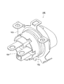
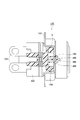
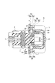
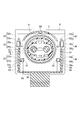
 図3~図9は、本発明の一実施形態を示す。本実施形態のシールドコネクタ1は、インバータケース(図示せず)に接続される高圧雌コネクタであり、インバータ内部にある端子台(図示せず)に嵌合することによりインバータに取り付けられる。なお、図9は、図8(縦断面図)に対応する斜視図で、ロック部35~38、52~54の構造を分かりやすく説明するため、ハウジング3、シールドシェル4及びプロテクタ5などを一部破断した状態で示してある。 3 to 9 show an embodiment of the present invention. The shield connector 1 of the present embodiment is a high-voltage female connector connected to an inverter case (not shown), and is attached to the inverter by being fitted to a terminal block (not shown) inside the inverter. FIG. 9 is a perspective view corresponding to FIG. 8 (longitudinal sectional view). In order to explain the structure of the lock portions 35 to 38 and 52 to 54 in an easy-to-understand manner, the housing 3, the shield shell 4, the protector 5, etc. It is shown in a partially broken state.
 シールドコネクタ1は、図3及び図4に示すように、左右一対の端子2を収容する略筒状のハウジング3と、ハウジング3の外周に配置されたシールドシェル4と、ハウジング3の電線引出部31の外周を覆うように配置されたプロテクタ5とを備えている。ハウジング3の外周面及びシールドシェル4の内周面間はシェルパッキン6により密封され、ハウジング3の外周にはユニットパッキン7が設けられている。 As shown in FIGS. 3 and 4, the shield connector 1 includes a substantially cylindrical housing 3 that accommodates a pair of left and right terminals 2, a shield shell 4 that is disposed on the outer periphery of the housing 3, and a wire lead-out portion of the housing 3. And a protector 5 arranged so as to cover the outer periphery of 31. A space between the outer peripheral surface of the housing 3 and the inner peripheral surface of the shield shell 4 is sealed with a shell packing 6, and a unit packing 7 is provided on the outer periphery of the housing 3.
 一対の端子2には電線21が接続されている。電線21は、ハウジング3内より電線引出方向(図9の矢印Aで示す方向)に延び、途中で下方に折り曲がると共に、ゴムブーツ22により覆われている。ゴムブーツ22は、プロテクタ5により覆われている。 An electric wire 21 is connected to the pair of terminals 2. The electric wire 21 extends from the inside of the housing 3 in the electric wire drawing direction (direction indicated by an arrow A in FIG. 9), is bent downward in the middle, and is covered with a rubber boot 22. The rubber boot 22 is covered with the protector 5.
 ハウジング3の後端側には、電線21を外部へ引き出すための電線引出部31と、電線引出方向の直交方向に張り出すフランジ部30とが設けられている。電線引出部31には、電線21を保持するリアホルダ32が設けられ、リアホルダ32より前端側に、ハウジング3及び電線21間を密封するゴム栓33が設けられている。 The rear end side of the housing 3 is provided with a wire drawing portion 31 for drawing the wire 21 to the outside and a flange portion 30 protruding in a direction orthogonal to the wire drawing direction. A rear holder 32 that holds the electric wire 21 is provided in the electric wire drawing portion 31, and a rubber plug 33 that seals between the housing 3 and the electric wire 21 is provided on the front end side of the rear holder 32.
 ハウジング3の電線引出部31側に位置するフランジ部30の面34には、プロテクタ5の後述する立設側部56の上方に配置される左右一対のハウジング側ロック部35、36が設けられている。これらのロック部35、36は、フランジ部30の面34より突出し、電線引出部31の電線引出方向に延びる被係止部35a、36aと、被係止部35a、36aに係止されたプロテクタ5に設けられたロック部52、53の電線引出方向への変移を阻止するストッパ部35b、36bとをそれぞれ有する。 A pair of left and right housing side lock portions 35, 36 disposed above a standing side portion 56 (to be described later) of the protector 5 is provided on the surface 34 of the flange portion 30 located on the side of the wire lead-out portion 31 of the housing 3. Yes. These lock portions 35, 36 protrude from the surface 34 of the flange portion 30, and are locked portions 35 a, 36 a extending in the wire drawing direction of the wire drawing portion 31, and protectors locked to the locked portions 35 a, 36 a. And stopper portions 35b and 36b for preventing the lock portions 52 and 53 provided in 5 from shifting in the wire drawing direction.
 ハウジング3には、左右一対のハウジング側ロック部35、36と共に、これより内側に配置される左右一対のハウジング側補助ロック部37、38がそれぞれ設けられている。これらの補助ロック部37、38は、フランジ部30の面34より突出し、電線引出部31の電線引出方向に延びる位置規制部37a、38aと、後述するプロテクタ側補助ロック部54の電線引出方向への変移を阻止するストッパ部37b、38bとをそれぞれ有する。 The housing 3 is provided with a pair of left and right housing side lock portions 35 and 36 and a pair of left and right housing side auxiliary lock portions 37 and 38 disposed inside thereof. These auxiliary lock portions 37 and 38 protrude from the surface 34 of the flange portion 30 and extend in the electric wire extraction direction of the electric wire extraction portion 31 and in the electric wire extraction direction of the protector side auxiliary lock portion 54 described later. And stopper portions 37b and 38b for preventing the above-described change.
 シールドシェル4には、ハウジング側ロック部35、36がそれぞれ挿通される挿通孔41,42と、ハウジング側補助ロック部37、38がそれぞれ挿通される挿通孔43,44とが設けられている。 The shield shell 4 is provided with insertion holes 41 and 42 through which the housing side lock portions 35 and 36 are inserted, and insertion holes 43 and 44 through which the housing side auxiliary lock portions 37 and 38 are inserted, respectively.
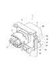
 プロテクタ5は、ベース部材5Aと、ベース部材5Aにヒンジ部51を介して上下開閉可能に設けられたカバー5Bとから構成されている。ベース部材5Aは、底板部55と底板部55の左右両端より立設された一対の立設側部56とを有する。カバー5Bは、ベース部材5Aの上面側、左右側面側及び後面側を覆う形状を有する。ヒンジ部51は、一方の立設側部56とカバー5Bの一端側を連結している。カバー5Bは、ヒンジ部51の撓み変形を利用してベース部材5Aの上面側、左右側面側及び後面側を覆う閉塞位置(図3、図4等の位置)と、これらの空間を開放する開放位置との間で変位できる。つまり、プロテクタ5は、ベース部材5Aとカバー5Bをヒンジ部51を介して連結され、カバー5Bがベース部材5Aの少なくとも組み付け方向(上面側)の領域を開閉可能に設けられている。カバー5Bは、閉塞位置では、ベース部材5Aの係止爪57とカバー5Bの係止穴58とが係止することによってベース部材5Aにロックされる(図3参照)。 The protector 5 includes a base member 5A and a cover 5B provided on the base member 5A via a hinge portion 51 so as to be opened and closed vertically. The base member 5 </ b> A includes a bottom plate portion 55 and a pair of standing side portions 56 that are erected from both left and right ends of the bottom plate portion 55. The cover 5B has a shape that covers the upper surface side, the left and right side surfaces, and the rear surface side of the base member 5A. The hinge part 51 connects one standing side part 56 and one end side of the cover 5B. The cover 5B uses the bending deformation of the hinge portion 51 to close the upper surface side, the left and right side surfaces, and the rear surface side of the base member 5A (open position for opening these spaces). Can be displaced between positions. That is, the protector 5 is configured such that the base member 5A and the cover 5B are connected via the hinge portion 51, and the cover 5B is provided so as to be able to open and close at least a region in the assembly direction (upper surface side) of the base member 5A. In the closed position, the cover 5B is locked to the base member 5A when the locking claw 57 of the base member 5A and the locking hole 58 of the cover 5B are locked (see FIG. 3).
 プロテクタ5の各立設側部56の上方には、ハウジング側ロック部35、36にそれぞれ係止される左右一対のプロテクタ側ロック部52、53が設けられている。これらのロック部52、53は、立設側部56より上方に突出し、電線引出方向の直交方向(図9の矢印B、Cで示す方向)に撓み変形するアーム部52a、53aと、アーム部52a、53aの先端側に設けられた係止爪部52b、53bとをそれぞれ有する。また、プロテクタ5の各立設側部56には、左右一対のプロテクタ側ロック部52、53と共に、左右一対のプロテクタ側補助ロック部54がそれぞれ設けられている。これらの補助ロック部54は、プロテクタ側ロック部52、53より内側に配置されている。補助ロック部54の上部には、上方ストッパ段差面54aが設けられている。プロテクタ5の組み付け時に、上方ストッパ段差面54aに位置規制部37a、38aがそれぞれ当接することにより、プロテクタ5の位置決めが行われる。 A pair of left and right protector side lock portions 52 and 53 that are respectively engaged with the housing side lock portions 35 and 36 are provided above the standing side portions 56 of the protector 5. These lock portions 52 and 53 protrude upward from the standing side portion 56, and are bent and deformed in the direction perpendicular to the wire drawing direction (directions indicated by arrows B and C in FIG. 9), and arm portions 52a and 53a. It has the latching claw parts 52b and 53b provided in the front end side of 52a and 53a, respectively. Each of the standing side portions 56 of the protector 5 is provided with a pair of left and right protector side lock portions 52 and 53 and a pair of left and right protector side auxiliary lock portions 54. These auxiliary lock portions 54 are arranged inside the protector side lock portions 52 and 53. An upper stopper step surface 54 a is provided on the auxiliary lock portion 54. When the protector 5 is assembled, the position restricting portions 37a and 38a come into contact with the upper stopper step surface 54a, whereby the protector 5 is positioned.
 上記構成において、シールドコネクタ1の組立時に、ハウジング3にシェルパッキン6及びシールドシェル4を装着して、ハウジング3に端子2、電線21、及びリアホルダ32を組み込み、電線21を覆うようにゴムブーツ22を装着し、カバー5Bを開放位置としたプロテクタ5を電線引出方向の直交方向(図9の矢印Dで示す方向)よりハウジング3に組み付けする。これにより、ハウジング3のフランジ部30の面(すなわち電線引出部31側の面)34に当接したシールドシェル4の箇所をハウジング3のフランジ部30とプロテクタ5に挟み込み、この状態でハウジング側ロック部35、36とプロテクタ側ロック部52、53を係止するので、シールドシェル4がプロテクタ5を介してハウジング3に固定される。プロテクタ5のカバー5Bを閉塞位置に変位させ、カバー5Bをベース部材5Aにロックする。これにより、ハウジング3の後面側より引き出された電線21の箇所がプロテクタ5で覆われる。 In the above configuration, when the shield connector 1 is assembled, the shell packing 6 and the shield shell 4 are attached to the housing 3, the terminal 2, the electric wire 21, and the rear holder 32 are assembled into the housing 3, and the rubber boot 22 is covered so as to cover the electric wire 21. The protector 5 is mounted and the cover 5B is in the open position, and is assembled to the housing 3 from the direction perpendicular to the wire drawing direction (direction indicated by arrow D in FIG. 9). As a result, the portion of the shield shell 4 in contact with the surface of the flange portion 30 of the housing 3 (that is, the surface on the wire lead-out portion 31 side) 34 is sandwiched between the flange portion 30 of the housing 3 and the protector 5. Since the portions 35 and 36 and the protector side lock portions 52 and 53 are locked, the shield shell 4 is fixed to the housing 3 via the protector 5. The cover 5B of the protector 5 is displaced to the closed position, and the cover 5B is locked to the base member 5A. Thereby, the part of the electric wire 21 drawn out from the rear surface side of the housing 3 is covered with the protector 5.
 また、上記のようにプロテクタ5が電線引出方向の直交方向よりハウジング3に組み付けされると、一対のプロテクタ側ロック部52、53は、アーム部52a、53aがそれぞれ互いに逆方向、すなわち図9の矢印B、Cで示す方向に撓み変形して各係止爪部52b、53bが被係止部35a、36aに係止する。同時に、一対のプロテクタ側補助ロック部54は、ハウジング側補助ロック部37、38の各位置規制部37a、38aと各ストッパ部37b、38bに係止する。 Further, when the protector 5 is assembled to the housing 3 from the direction perpendicular to the electric wire drawing direction as described above, the pair of protector side lock portions 52 and 53 have arm portions 52a and 53a in opposite directions, that is, as shown in FIG. The locking claws 52b and 53b are locked to the locked portions 35a and 36a by being bent and deformed in the directions indicated by the arrows B and C. At the same time, the pair of protector-side auxiliary lock portions 54 engages with the position restricting portions 37a and 38a and the stopper portions 37b and 38b of the housing-side auxiliary lock portions 37 and 38, respectively.
 以上説明したように、ハウジング3の電線引出部31側に位置するフランジ部30の面34にシールドシェル4を当接した状態でシールドシェル4をハウジング3に固定できる。このため、ハウジング3の電線引出部31側の面34にシールドシェル4を固定するための隙間が必要なく、シールドコネクタ1の小型化を図ることができる。 As described above, the shield shell 4 can be fixed to the housing 3 in a state where the shield shell 4 is in contact with the surface 34 of the flange portion 30 located on the wire lead-out portion 31 side of the housing 3. For this reason, the clearance for fixing the shield shell 4 to the surface 34 of the housing 3 on the wire lead-out portion 31 side is not necessary, and the shield connector 1 can be downsized.
 プロテクタ5は、ベース部材5Aとカバー5Bをヒンジ部51を介して連結され、カバー5Bがベース部材5Aの少なくとも組み付け方向の領域を開閉可能に設けられている。従って、プロテクタ5をハウジング3の電線引出方向の直交方向より組み付けする際に、カバー5Bを電線Wに干渉させることなくベース部材5Aを所定の組み付け位置に移動でき、プロテクタ5の組み付けができる。カバー5Bは、ヒンジ部51を介してベース部材5Aに連結されているため、カバー5Bのベース部材5Aへの組み付けを容易、且つ、確実に行うことができる。又、プロテクタ5の組み付け後に、閉塞位置のカバーBを開放位置とすることによってプロテクタ5内の状態を容易に確認できる。カバー5Bは、ヒンジ部51を介してベース部材5Aに連結されない分離された部材であっても良い。 The protector 5 has a base member 5A and a cover 5B connected to each other via a hinge portion 51, and the cover 5B is provided so as to be able to open and close at least an area in the assembly direction of the base member 5A. Therefore, when the protector 5 is assembled from the direction orthogonal to the electric wire drawing direction of the housing 3, the base member 5A can be moved to a predetermined assembling position without causing the cover 5B to interfere with the electric wire W, and the protector 5 can be assembled. Since the cover 5B is connected to the base member 5A via the hinge portion 51, the cover 5B can be easily and reliably assembled to the base member 5A. In addition, after the protector 5 is assembled, the state in the protector 5 can be easily confirmed by setting the cover B in the closed position to the open position. The cover 5B may be a separated member that is not connected to the base member 5A via the hinge portion 51.
 プロテクタ5とハウジング3間は、組み付け解除方向(図9の矢印Eで示す方向)について、各係止爪部52b、53b及び各被係止部35a、36aによって変移が阻止され、電線引出方向(すなわちプロテクタ5とハウジング3の離間方向)について、アーム部52a、53aとストッパ部35b、36bとによって変移が阻止される。従って、プロテクタ5とハウジング3間は、強固に固定される。このため、シールドシェル4をハウジング3に強固に固定できる。 Transition between the protector 5 and the housing 3 in the assembly release direction (the direction indicated by the arrow E in FIG. 9) is prevented by the locking claw portions 52b and 53b and the locked portions 35a and 36a, and the wire drawing direction ( That is, the movement of the protector 5 and the housing 3 is prevented by the arm portions 52a and 53a and the stopper portions 35b and 36b. Accordingly, the protector 5 and the housing 3 are firmly fixed. For this reason, the shield shell 4 can be firmly fixed to the housing 3.
 一対のハウジング側補助ロック部37、38とプロテクタ側補助ロック部54は、アーム部52a、53aの撓み方向への変移と電線引出方向への変移を阻止するため、プロテクタ5とハウジング3間は、更に強固に固定される。このため、シールドシェル4をハウジング3に更に強固に固定できる。 The pair of housing side auxiliary lock portions 37 and 38 and the protector side auxiliary lock portion 54 prevent the arm portions 52a and 53a from shifting in the bending direction and the wire drawing direction. Furthermore, it is firmly fixed. For this reason, the shield shell 4 can be more firmly fixed to the housing 3.
 プロテクタ5の外側に露出する状態でプロテクタ側ロック部52、53とハウジング側ロック部35、36が係止するので、プロテクタ5の外部から目視で係止の有無を確認できる。 Since the protector- side lock portions 52 and 53 and the housing- side lock portions 35 and 36 are locked while being exposed to the outside of the protector 5, the presence or absence of the lock can be confirmed visually from the outside of the protector 5.
 このように、本発明は、ここでは記載していない様々な実施の形態などを含むことは勿論である。したがって、本発明の技術的範囲は、上述の説明から妥当な特許請求の範囲に係る発明特定事項によってのみ定められる。 Thus, it goes without saying that the present invention includes various embodiments that are not described herein. Therefore, the technical scope of the present invention is determined only by the invention specifying matters according to the scope of claims reasonable from the above description.
 特願2013-097412号(出願日:2013年5月7日)の全内容は、ここに援用される。 The entire contents of Japanese Patent Application No. 2013-097412 (filing date: May 7, 2013) are incorporated herein by reference.

Claims (4)

  1.  端子を収容し、電線引出部と前記電線引出部側の面に設けられたハウジング側ロック部とを有するハウジングと、
     前記ハウジングの外周に配置されたシールドシェルと、
     前記ハウジング側ロック部と係止するプロテクタ側ロック部を有し、前記ハウジングの前記電線引出部の外周を覆うように配置されるプロテクタと、
    を備え、
      前記ハウジング側ロック部と前記プロテクタ側ロック部とは、前記ハウジングの前記電線引出部側の面に当接した前記シールドシェルの箇所が前記ハウジングと前記プロテクタとに挟み込まれた状態で、互いに係止して、前記シールドシェルを前記プロテクタを介して前記ハウジングに固定する
    シールドコネクタ。
    A housing that accommodates the terminal and has a wire lead-out portion and a housing-side lock portion provided on a surface on the wire lead-out portion side;
    A shield shell disposed on the outer periphery of the housing;
    A protector-side lock portion that engages with the housing-side lock portion, and a protector disposed so as to cover the outer periphery of the wire lead-out portion of the housing;
    With
    The housing-side lock portion and the protector-side lock portion are locked with each other in a state where the portion of the shield shell that is in contact with the surface of the housing on the side of the wire lead-out portion is sandwiched between the housing and the protector. And the shield connector which fixes the said shield shell to the said housing via the said protector.
  2.  前記プロテクタは、
      ベース部材と、
      前記ベース部材とヒンジ部を介して連結され、前記ベース部材の少なくとも組み付け方向の領域を開閉可能に設けられたカバーと、
    を備えた
    請求項1記載のシールドコネクタ。
    The protector is
    A base member;
    A cover that is connected to the base member via a hinge part, and that is provided so as to be able to open and close at least an area in the assembly direction of the base member;
    The shield connector according to claim 1, further comprising:
  3.  前記ハウジング側ロック部及び前記プロテクタ側ロック部は、左右一対設けられ、
     前記一対のハウジング側ロック部のそれぞれは、
      前記電線引出部の電線引出方向に延びる被係止部と、
      前記被係止部に係止された前記プロテクタ側ロック部の前記電線引出方向への変移を阻止するストッパ部と、
    を有し、
     前記一対のプロテクタ側ロック部のそれぞれは、
      前記電線引出方向の直交方向に撓み変形するアーム部と、
      前記アーム部の先端側に設けられた係止爪部と、
    を有し、
     前記プロテクタが前記電線引出方向の直交方向より前記ハウジングに組み付けされると、前記アーム部がそれぞれ互いに逆方向に撓み変形して前記各係止爪部が前記被係止部に係止する
    請求項1又は請求項2に記載のシールドコネクタ。
    The housing side lock portion and the protector side lock portion are provided in a pair of left and right,
    Each of the pair of housing side lock portions is
    A locked portion extending in the wire drawing direction of the wire drawing portion;
    A stopper portion that prevents the protector-side lock portion locked to the locked portion from shifting in the wire drawing direction;
    Have
    Each of the pair of protector side lock portions is
    An arm portion that bends and deforms in a direction perpendicular to the wire drawing direction;
    A locking claw provided on the tip side of the arm,
    Have
    When the protector is assembled to the housing from a direction orthogonal to the electric wire drawing direction, the arm portions are bent and deformed in opposite directions, and the locking claws are locked to the locked portions. The shield connector according to claim 1 or 2.
  4.  前記ハウジングは、一対のハウジング側補助ロック部を有し、
     前記プロテクタは、一対のプロテクタ側補助ロック部を有し、
     前記一対のハウジング側補助ロック部のそれぞれは、
      前記電線引出部の前記電線引出方向に延びる位置規制部と、
      前記プロテクタ側補助ロック部の前記電線引出方向への変移を阻止するストッパ部と、
    を有し、
     前記プロテクタが前記電線引出方向の直交方向より前記ハウジングに組み付けされると、前記一対のプロテクタ側補助ロック部は、前記一対のハウジング側補助ロック部の前記各位置規制部と前記各ストッパ部に係止する
    請求項3記載のシールドコネクタ。
    The housing has a pair of housing side auxiliary lock portions,
    The protector has a pair of protector side auxiliary lock parts,
    Each of the pair of housing side auxiliary lock portions is
    A position restricting portion extending in the wire drawing direction of the wire drawing portion;
    A stopper portion that prevents the protector side auxiliary lock portion from shifting in the wire drawing direction;
    Have
    When the protector is assembled to the housing from a direction orthogonal to the wire drawing direction, the pair of protector side auxiliary lock portions are engaged with the position restricting portions and the stopper portions of the pair of housing side auxiliary lock portions. The shield connector according to claim 3, wherein the shield connector is stopped.
PCT/JP2014/061055 2013-05-07 2014-04-18 Shield connector WO2014181663A1 (en)

Priority Applications (3)

Application Number Priority Date Filing Date Title
CN201480025072.XA CN105164868A (en) 2013-05-07 2014-04-18 Shield connector
DE112014002316.7T DE112014002316B4 (en) 2013-05-07 2014-04-18 Shielded connector
US14/930,699 US9640916B2 (en) 2013-05-07 2015-11-03 Shield connector

Applications Claiming Priority (2)

Application Number Priority Date Filing Date Title
JP2013-097412 2013-05-07
JP2013097412A JP6055370B2 (en) 2013-05-07 2013-05-07 Shield connector

Related Child Applications (1)

Application Number Title Priority Date Filing Date
US14/930,699 Continuation US9640916B2 (en) 2013-05-07 2015-11-03 Shield connector

Publications (1)

Publication Number Publication Date
WO2014181663A1 true WO2014181663A1 (en) 2014-11-13

Family

ID=51867145

Family Applications (1)

Application Number Title Priority Date Filing Date
PCT/JP2014/061055 WO2014181663A1 (en) 2013-05-07 2014-04-18 Shield connector

Country Status (5)

Country Link
US (1) US9640916B2 (en)
JP (1) JP6055370B2 (en)
CN (1) CN105164868A (en)
DE (1) DE112014002316B4 (en)
WO (1) WO2014181663A1 (en)

Families Citing this family (4)

* Cited by examiner, † Cited by third party
Publication number Priority date Publication date Assignee Title
DE102015114040B3 (en) * 2015-08-24 2016-12-29 Erni Production Gmbh & Co. Kg Cable connector with a shielding sleeve and method for its manufacture
JP6364434B2 (en) * 2016-03-01 2018-07-25 矢崎総業株式会社 Shield connector fixing structure
JP6634420B2 (en) * 2017-08-28 2020-01-22 矢崎総業株式会社 Shield connector for device direct mounting
JP7191487B2 (en) * 2020-08-13 2022-12-19 矢崎総業株式会社 connector

Citations (2)

* Cited by examiner, † Cited by third party
Publication number Priority date Publication date Assignee Title
JP2009087888A (en) * 2007-10-03 2009-04-23 Yazaki Corp Shielded connector
JP2010211935A (en) * 2009-03-06 2010-09-24 Yazaki Corp High-voltage electric line l-shaped connector

Family Cites Families (8)

* Cited by examiner, † Cited by third party
Publication number Priority date Publication date Assignee Title
JP2921634B2 (en) * 1993-11-26 1999-07-19 矢崎総業株式会社 Waterproof shield connector
JP3230970B2 (en) * 1995-12-07 2001-11-19 矢崎総業株式会社 Connector shield structure
JP2004288545A (en) * 2003-03-24 2004-10-14 Yazaki Corp Protector for connector
DE102008004801B4 (en) * 2007-02-02 2011-12-08 Japan Aviation Electronics Industry, Ltd. Connector and device equipped therewith
KR101586477B1 (en) * 2009-11-09 2016-01-18 한국단자공업 주식회사 connector
US8147272B2 (en) * 2010-02-04 2012-04-03 Tyco Electronics Corporation Header connector assembly
KR101255790B1 (en) * 2011-07-21 2013-04-23 주식회사 유라코퍼레이션 Shield Connector
EP2795735B1 (en) * 2011-12-22 2015-12-09 Delphi International Operations Luxembourg S.à r.l. Electrical connector, its assembly and its method of manufacture

Patent Citations (2)

* Cited by examiner, † Cited by third party
Publication number Priority date Publication date Assignee Title
JP2009087888A (en) * 2007-10-03 2009-04-23 Yazaki Corp Shielded connector
JP2010211935A (en) * 2009-03-06 2010-09-24 Yazaki Corp High-voltage electric line l-shaped connector

Also Published As

Publication number Publication date
US9640916B2 (en) 2017-05-02
DE112014002316B4 (en) 2017-08-03
CN105164868A (en) 2015-12-16
JP2014220060A (en) 2014-11-20
JP6055370B2 (en) 2016-12-27
US20160056584A1 (en) 2016-02-25
DE112014002316T5 (en) 2016-01-21

Similar Documents

Publication Publication Date Title
JP5952607B2 (en) Waterproof shield connector
WO2018163788A1 (en) Shielded terminal and shielded connector
JP4999175B2 (en) Shield connector
US9728890B2 (en) Electric wire holder having a hole with an internal diameter smaller than an external diameter of an accommodated electric wire
JP2004288545A (en) Protector for connector
JP2009541919A (en) Electrical connector
WO2014181663A1 (en) Shield connector
WO2017051703A1 (en) Connector
WO2012157503A1 (en) Waterproof connector
JP2016207416A (en) connector
WO2018163787A1 (en) Shielded terminal and shielded connector
JP4984563B2 (en) Electronic device connector retaining structure.
JP5809083B2 (en) Waterproof connector
JP2016207414A (en) connector
KR100733849B1 (en) Female terminal
JP2014060073A (en) Connector
JP4918410B2 (en) Connector with protector
JP5863181B2 (en) connector
JP2017112003A (en) connector
WO2017217208A9 (en) Connector
JP5193790B2 (en) Waterproof connector
JP2010092614A (en) Connector
JP6746392B2 (en) Switch device with cover
TW201442357A (en) Receptacle guard cover and electronic equipment
JP6263057B2 (en) Connector connection structure

Legal Events

Date Code Title Description
WWE Wipo information: entry into national phase

Ref document number: 201480025072.X

Country of ref document: CN

121 Ep: the epo has been informed by wipo that ep was designated in this application

Ref document number: 14794454

Country of ref document: EP

Kind code of ref document: A1

WWE Wipo information: entry into national phase

Ref document number: 112014002316

Country of ref document: DE

Ref document number: 1120140023167

Country of ref document: DE

122 Ep: pct application non-entry in european phase

Ref document number: 14794454

Country of ref document: EP

Kind code of ref document: A1