WO2014181446A1 - Communications system, control device, and control method - Google Patents
Communications system, control device, and control method Download PDFInfo
- Publication number
- WO2014181446A1 WO2014181446A1 PCT/JP2013/063091 JP2013063091W WO2014181446A1 WO 2014181446 A1 WO2014181446 A1 WO 2014181446A1 JP 2013063091 W JP2013063091 W JP 2013063091W WO 2014181446 A1 WO2014181446 A1 WO 2014181446A1
- Authority
- WO
- WIPO (PCT)
- Prior art keywords
- communication device
- communication
- signal
- terminal
- measurement signal
- Prior art date
Links
Images


Classifications
-
- H—ELECTRICITY
- H04—ELECTRIC COMMUNICATION TECHNIQUE
- H04W—WIRELESS COMMUNICATION NETWORKS
- H04W24/00—Supervisory, monitoring or testing arrangements
- H04W24/10—Scheduling measurement reports ; Arrangements for measurement reports
Definitions
- the present invention relates to a communication system, a control device, and a control method.
- LTE Long Term Evolution
- LTE-A Long Term Evolution-Advanced
- an object of the present invention is to provide a communication system, a control device, and a control method capable of measuring communication quality while suppressing interference.
- FIG. 1A is a diagram of an example of a communication system according to the first embodiment.
- 1B is a diagram illustrating an example of a signal flow in the communication system illustrated in FIG. 1A.
- FIG. 2A is a diagram (part 1) illustrating an example of a communication system according to a second embodiment.
- FIG. 2B is a diagram (part 2) illustrating an example of a communication system according to the second embodiment.
- FIG. 2C is a diagram (part 3) illustrating an example of a communication system according to the second embodiment.
- FIG. 2D is a diagram (part 4) illustrating an example of a communication system according to the second embodiment.
- FIG. 3 is a diagram illustrating an example of correspondence information between the waveform pattern parameter and the transmission power of the measurement signal.
- FIG. 4A is a diagram illustrating an example of a configuration of a base station.
- 4B is a diagram illustrating an example of a signal flow in the configuration of the base station illustrated in FIG. 4A.
- FIG. 5A is a diagram illustrating an exemplary configuration of a terminal.
- FIG. 5B is a diagram illustrating an example of a signal flow in the configuration of the terminal illustrated in FIG. 5A.
- FIG. 6 is a flowchart illustrating an example of processing by the base station.
- FIG. 7 is a flowchart illustrating an example of processing by the terminal.
- FIG. 8 is a sequence diagram illustrating an example of a measurement operation in the communication system.
- FIG. 9 is a diagram illustrating an example of PSS transmission timing.
- FIG. 10 is a diagram illustrating an example of grouping of transmission powers of measurement signals.
- FIG. 11 is a flowchart illustrating an example of processing for determining the transmission power of a measurement signal.
- FIG. 1A is a diagram of an example of a communication system according to the first embodiment.
- 1B is a diagram illustrating an example of a signal flow in the communication system illustrated in FIG. 1A.
- the communication system 100 according to the first embodiment includes a first communication device 110, a second communication device 120, a third communication device 130, and a control device 140.
- the first communication device 110, the second communication device 120, and the third communication device 130 are devices capable of wireless communication.
- the control device 140 can communicate with the second communication device 120 and the third communication device 130 via wireless communication by the first communication device 110.
- the control device 140 can communicate with the first communication device 110 outside the first communication device 110. It may be a device.
- the first communication device 110 includes a transmission unit 111 and a control device 140.
- the transmission unit 111 wirelessly transmits a synchronization signal.
- the synchronization signal is a periodic signal having a predetermined waveform pattern for another communication device to synchronize wireless communication with the first communication device 110.
- At least one of the second communication device 120 and the third communication device 130 is a communication device that is wirelessly connected to the first communication device 110.
- both the second communication device 120 and the third communication device 130 are wirelessly connected to the first communication device 110, but one of the second communication device 120 and the third communication device 130 is
- the wireless communication device may be wirelessly connected to another communication device that can communicate with the first communication device 110.
- the second communication device 120 and the third communication device 130 can directly communicate with each other wirelessly.
- the control device 140 includes a control unit 141 and a reception unit 142.
- the control unit 141 has a waveform pattern orthogonal to the synchronization signal transmitted by the transmission unit 111 and the measurement signal having the same frequency band as the synchronization signal transmitted by the transmission unit 111 in accordance with the transmission timing of the synchronization signal by the transmission unit 111. Control to wirelessly transmit from the second communication device 120 is performed.
- the control unit 141 transmits a measurement signal from the second communication device 120 by transmitting a control signal including a parameter capable of deriving a waveform pattern orthogonal to the synchronization signal transmitted by the transmission unit 111 to the second communication device 120. Let it transmit wirelessly. Further, the control unit 141 may further notify the second communication device 120 of the frequency of the measurement signal. The control unit 141 may also transmit a control signal including a parameter that can derive a waveform pattern orthogonal to the synchronization signal transmitted by the transmission unit 111 to the third communication device 130.
- the receiving unit 142 receives from the third communication device 130 the reception result of the measurement signal wirelessly transmitted from the second communication device 120 by the third communication device 130 under the control of the control unit 141.
- the second communication device 120 includes a reception unit 121 and a transmission unit 122.
- the receiving unit 121 receives a control signal transmitted from the control device 140. Then, the reception unit 121 outputs the parameters included in the received control signal to the transmission unit 122.
- the transmission unit 122 generates a measurement signal whose waveform pattern is orthogonal to the synchronization signal wirelessly transmitted by the first communication device 110 based on the parameter output from the reception unit 121. Then, the transmission unit 122 wirelessly transmits the generated measurement signal in accordance with the transmission timing of the synchronization signal by the first communication device 110.
- the reception unit 131 outputs the reception result of the measurement signal to the transmission unit 132.
- the reception result of the measurement signal can be, for example, the reception power (reception power) of the measurement signal in the third communication device 130.
- the reception result of the measurement signal may be a propagation loss (path loss) based on a comparison between the transmission power of the measurement signal in the second communication device 120 and the reception power of the measurement signal in the third communication device 130.
- the transmission unit 132 transmits the reception result output from the reception unit 131 to the control device 140. Accordingly, the control device 140 can obtain a reception result of the measurement signal wirelessly transmitted from the second communication device 120 in the third communication device 130. For this reason, the communication quality between the 2nd communication apparatus 120 and the 3rd communication apparatus 130 can be measured.
- the second communication device 120 and the second communication device 120 are connected to the second communication device 120 using the measurement signal of the same radio resource (time and frequency) as the synchronization signal wirelessly transmitted by the first communication device 110.
- the communication quality with the three communication devices 130 can be measured. Thereby, it is possible to measure the communication quality between the second communication device 120 and the third communication device 130 without vacating radio resources for the measurement signal. For this reason, the compression of the radio
- the cross-correlation value between the synchronization signal and the measurement signal can be obtained by using the measurement signal whose waveform pattern is orthogonal to the synchronization signal. Can be lowered. For this reason, the interference by the measurement signal with respect to the synchronous signal which the 1st communication apparatus 110 transmits can be suppressed.
- the communication quality between the second communication device 120 and the third communication device 130 can be measured while suppressing interference with the communication of the first communication device 110.
- the transmission power of the measurement signal from the second communication device 120 may be determined by the control device 140.
- the second communication device 120, the third communication device 130, and the control device 140 share correspondence information that associates the waveform pattern parameter notified by the control device 140 with the transmission power of the measurement signal.
- the control device 140 selects a parameter corresponding to the determined transmission power among the parameters capable of deriving a waveform pattern orthogonal to the synchronization signal transmitted by the transmission unit 111 based on the correspondence information. Then, control device 140 transmits a control signal including the selected parameter to second communication device 120 and third communication device 130.
- the transmission unit 122 of the second communication device 120 wirelessly transmits the measurement signal with the transmission power corresponding to the parameter included in the control signal received by the reception unit 121 based on the correspondence information.
- the receiving unit 131 of the third communication device 130 specifies the transmission power corresponding to the parameter included in the control signal transmitted from the control device 140 based on the correspondence information. Then, the reception unit 131 calculates the propagation loss of the measurement signal based on the comparison between the specified transmission power and the reception power of the received measurement signal.
- the transmission power of the measurement signal can be notified to the second communication device 120 and the third communication device 130 using the parameter for notifying the waveform pattern of the measurement signal. Thereby, the information amount of a control signal can be reduced.
- the control device 140 may calculate the propagation loss of the measurement signal based on a comparison between the determined transmission power of the measurement signal and the reception power transmitted as the reception result from the third communication device 130. .
- the base station 210 transmits PSS (Primary Synchronization Signal) periodically (every 5 ms in the latest 3GPP LTE specifications).
- PSS Primary Synchronization Signal
- the waveform pattern of the PSS transmitted by the base station 210 is associated with the cell ID of the base station 210, for example.
- SSS Secondary Synchronization Signal
- both PSS and SSS are transmitted on the radio downlink.
- the physical layer ID (PCI: Physical Cell ID) of each radio cell (Cell) of the base station is associated with both PSS and SSS, and the terminal receives both PSS and SSS so that they are transmitted. It becomes possible to know the PCI of the wireless cell.
- one base station forms a plurality of radio cells, and one radio cell is composed of only Pcell (Primary Cell), or further composed of Pcell and one or more Scell (Secondary Cell).
- the first terminal 221, the second terminal 222, and the third terminal 223 are wireless communication terminals capable of wireless communication with the base station 210.
- the wireless communication terminal is also called UE (User Equipment) or MS (Mobile Station).
- the first terminal 221, the second terminal 222, and the third terminal 223 can synchronize wireless communication with the base station 210 by detecting the PSS transmitted from the base station 210.
- a PSS is transmitted for each radio cell of a base station, and the parameter values for determining the PSS signal waveform are set to be different between PSSs transmitted between the radio cells. The same value may be used between different wireless cells.
- the first terminal 221 and the second terminal 222 can directly communicate with each other wirelessly under moderate control by the base station 210.
- the first communication device 110 and the control device 140 illustrated in FIGS. 1A and 1B can be realized by the base station 210, for example.
- the second communication device 120 illustrated in FIGS. 1A and 1B can be realized by the first terminal 221, for example.
- the third communication device 130 illustrated in FIGS. 1A and 1B can be realized by the second terminal 222, for example.
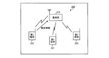
- the base station 210 determines whether direct communication between the first terminal 221 and the second terminal 222 is possible. For this purpose, the base station 210 performs control to cause the measurement signal from the first terminal 221 to be wirelessly transmitted and the measurement signal from the first terminal 221 to be received by the second terminal 222 as illustrated in FIG. 2B.
- the second terminal 222 wirelessly transmits to the base station 210 report information indicating a reception result at the second terminal 222 of the measurement signal wirelessly transmitted from the first terminal 221.
- Base station 210 determines whether direct communication between first terminal 221 and second terminal 222 is possible based on the report information received from second terminal 222.
- the base station 210 determines that direct communication is possible, the base station 210 transmits a control signal to the first terminal 221 and the second terminal 222, as shown in FIG. 2 Direct communication with the terminal 222 is started.
- the band in the direct communication between the first terminal 221 and the second terminal 222 may be a band used by the base station 210 with the terminal, for example.
- the base station 210 causes the first terminal 221 to transmit a measurement signal whose waveform pattern is orthogonal to the PSS transmitted by the base station 210 at the same time and frequency as the PSS transmitted by the base station 210.
- the communication quality between the first terminal 221 and the second terminal 222 can be measured without vacating radio resources for the measurement signal. For this reason, it is possible to suppress the compression of radio resources due to the measurement signal.
- the cross-correlation value between the PSS of the base station 210 and the measurement signal can be lowered. For this reason, the interference by the measurement signal with respect to the PSS transmitted from the base station 210 can be suppressed. For example, interference by the measurement signal from the first terminal 221 when the third terminal 223 detects and synchronizes the PSS transmitted by the base station 210 can be suppressed.
- FIG. 3 is a diagram illustrating an example of correspondence information between the waveform pattern parameter and the transmission power of the measurement signal.
- the base station 210, the first terminal 221 and the second terminal 222 store, for example, correspondence information 300 shown in FIG. 3 in respective memories.
- the parameter u of the correspondence information 300 is a parameter that can derive a waveform pattern in which the waveform pattern is orthogonal to the PSS transmitted by the base station 210.
- the transmission power (P1, P2,...) Of the correspondence information 300 is the transmission power of the measurement signal (for example, the absolute value of the transmission power).
- the base station 210 determines the transmission power of the measurement signal
- the base station 210 selects the parameter u corresponding to the determined power from the parameters u of the correspondence information 300. Then, the base station 210 transmits a control signal including the selected parameter u to the first terminal 221 and the second terminal 222.
- the control signal for example, PDCCH (Physical Downlink Control Channel: physical downlink control channel) or E-PDCCH (Enhanced-Physical Downlink Control Channel: extended physical downlink control channel) can be used.
- PDSCH Physical Downlink Shared Channel
- Layer2 Mac Layer
- the first terminal 221 generates and transmits a parameter pattern PSS based on the parameter u included in the control signal received from the base station 210 and the above equation (1) as a measurement signal. In addition, the first terminal 221 sets the transmission power of the measurement signal as the transmission power corresponding to the parameter u in the correspondence information 300.
- the second terminal 222 generates a replica signal having a waveform pattern based on the parameter u included in the control signal received from the base station 210 and the above equation (1). Then, the second terminal 222 detects the measurement signal transmitted from the first terminal 221 by comparing the received signal with the replica signal. Further, the second terminal 222 acquires the transmission power corresponding to the parameter u in the correspondence information 300, and compares it with the received power of the detected measurement signal, thereby causing a path loss between the first terminal 221 and the second terminal 222. Is calculated. Then, the second terminal 222 transmits report information including the calculated path loss to the base station 210. This report information may include other radio measurement results.
- the report information is transmitted to the base station 210 using PUSCH (Physical Uplink Shared Channel) used in the radio uplink.
- PUSCH Physical Uplink Shared Channel
- PUCCH Physical Uplink Control Channel
- Various radio parameters of PUSCH or PUCCH to be used and resource information of PUSCH or PUCCH used by the terminal (information indicating the frequency position of PRB: Physical Resource Block directly or indirectly) is previously determined using the PDSCH. Or notified to the terminal using PDCCH or E-PDCCH.
- PRB information indicating the frequency location of the Physical Resource Block directly or indirectly
- information indicating directly or indirectly that the PUSCH or PUCCH is used for the purpose of transmitting report information may be included.
- the transmission power of the measurement signal can be notified to the first terminal 221 and the second terminal 222 using the parameter u for notifying the waveform pattern of the measurement signal. Thereby, the information amount of a control signal can be reduced.
- the parameter u may not be directly associated with the transmission power, but may be information that associates the parameter u with the difference between the transmission power of the reference signal from the base station 210.
- the reference signal is a reference signal transmitted by the base station 210, and is, for example, CRS (cell specific reference signal) or CSI RS.
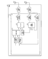
- FIG. 4A is a diagram illustrating an example of a configuration of a base station.
- 4B is a diagram illustrating an example of a signal flow in the configuration of the base station illustrated in FIG. 4A.
- the base station 210 shown in FIGS. 2A to 2D can be realized by the base station 400 shown in FIGS. 4A and 4B, for example.
- the base station 400 includes a control signal generation unit 411, a data signal generation unit 412, multiplexing units 413 and 414, an encoding / modulation unit 415, an RF transmission circuit 416, and a transmission antenna 417.
- the base station 400 includes a reception antenna 421, an RF reception circuit 422, a demodulation / decoding unit 423, and a demultiplexing unit 424.
- the control signal generation unit 411, the data signal generation unit 412, the multiplexing units 413 and 414, the encoding / modulation unit 415, the demodulation / decoding unit 423, and the demultiplexing unit 424 are, for example, LSI 401 (Large Scale Integration: large scale integrated circuit). Can be realized.
- the control signal generation unit 411 generates a control signal for the base station 400 to wirelessly transmit.
- the control signal generated by the control signal generation unit 411 includes, for example, PSS transmission instruction information, PSS transmission stop instruction information, PSS detection instruction information, and other control information.
- the control signal generation unit 411 outputs the generated control signal to the multiplexing unit 413.
- the data signal generator 412 generates a data signal for the base station 400 to wirelessly transmit based on the input user data. Then, the data signal generation unit 412 outputs the generated data signal to the multiplexing unit 413.
- the encoding / modulation unit 415 encodes and modulates the signal output from the multiplexing unit 414.
- the encoding by the encoding / modulation unit 415 includes, for example, addition of a parity code for error correction and generation of a code string having an encoding rate that provides required characteristics. Then, encoding / modulation section 415 outputs a signal obtained by encoding and modulation to RF transmission circuit 416.
- the demodulation / decoding unit 423 performs demodulation and decoding of the signal output from the RF reception circuit 422.
- Demodulation / decoding section 423 outputs a signal obtained by demodulation and decoding to demultiplexing section 424.
- the demultiplexing unit 424 demultiplexes the signal output from the demodulation / decoding unit 423. Then, the demultiplexing unit 424 outputs each demultiplexed signal.
- Each signal output from the demultiplexing unit 424 includes, for example, PSS reception result report information, other control information, user data, and the like.
- the 1A and 1B can be realized by an RF transmission circuit 416 and a transmission antenna 417, for example.
- the control unit 141 shown in FIGS. 1A and 1B can be realized by, for example, a control signal generation unit 411, a multiplexing unit 413, a multiplexing unit 414, an encoding / modulation unit 415, an RF transmission circuit 416, and a transmission antenna 417. it can.
- the receiving unit 142 illustrated in FIGS. 1A and 1B can be realized by, for example, the receiving antenna 421, the RF receiving circuit 422, the demodulation / decoding unit 423, and the demultiplexing unit 424.
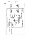
- FIG. 5A is a diagram illustrating an exemplary configuration of a terminal.
- FIG. 5B is a diagram illustrating an example of a signal flow in the configuration of the terminal illustrated in FIG. 5A.
- Each of first terminal 221 and second terminal 222 shown in FIGS. 2A to 2D can be realized by terminal 500 shown in FIGS. 5A and 5B, for example.
- the terminal 500 includes a data signal generation unit 511, a control signal generation unit 512, a multiplexing unit 513, a PSS generation unit 514, a switch 515, an encoding / modulation unit 516, an RF transmission circuit 517, and a transmission antenna. 518.
- Terminal 500 includes a receiving antenna 521, an RF receiving circuit 522, a demodulation / decoding unit 523, a demultiplexing unit 524, and a PSS detection unit 525.
- the data signal generation unit 511, the control signal generation unit 512, the multiplexing unit 513, the PSS generation unit 514, the switch 515, the encoding / modulation unit 516, the demodulation / decoding unit 523, the demultiplexing unit 524, and the PSS detection unit 525 are, for example, It can be realized by the LSI 501.
- the control signal generation unit 512 generates a control signal for the terminal 500 to wirelessly transmit.
- the control signal generated by the control signal generator 512 includes, for example, PSS reception result report information and other control information.
- the control signal generation unit 512 outputs the generated control signal to the multiplexing unit 513.
- the multiplexing unit 513 multiplexes the input pilot signal (or reference signal), the data signal output from the data signal generation unit 511, and the control signal output from the control signal generation unit 512. Then, multiplexing section 513 outputs a signal obtained by multiplexing to switch 515.
- the PSS generation unit 514 When the PSS transmission instruction information is output from the demultiplexing unit 524, the PSS generation unit 514 generates a PSS based on the PSS transmission instruction information. Specifically, the PSS generator 514 generates a waveform pattern PSS based on the parameter u included in the transmission instruction information and the above equation (1). Then, the PSS generation unit 514 outputs the generated PSS to the switch 515. Further, when the PSS transmission stop instruction information is output from the demultiplexing unit 524, the PSS generation unit 514 stops generating the PSS.
- the encoding / modulation unit 516 encodes and modulates the signal output from the switch 515.
- the encoding by the encoding / modulation unit 516 includes, for example, addition of a parity code for error correction, generation of a code string having an encoding rate that provides required characteristics, and the like. Then, encoding / modulation section 516 outputs a signal obtained by encoding and modulation to RF transmission circuit 517.
- the receiving antenna 521 receives a signal wirelessly transmitted from another communication device (for example, the base station 400). Then, the reception antenna 521 outputs the received signal to the RF reception circuit 522.
- the RF reception circuit 522 performs an RF reception process on the signal output from the reception antenna 521.
- the RF reception processing performed by the RF reception circuit 522 includes, for example, frequency conversion and analog to digital conversion.
- the RF reception circuit 522 outputs a signal obtained by the RF reception process to the demodulation / decoding unit 523 and the PSS detection unit 525.
- the demultiplexing unit 524 demultiplexes the signal output from the demodulation / decoding unit 523. Then, the demultiplexing unit 524 outputs each demultiplexed signal.
- Each signal output from the demultiplexing unit 524 includes, for example, PSS transmission instruction information, PSS transmission stop instruction information, PSS detection instruction information, other control information, user data, and the like.
- the demultiplexing unit 524 outputs the PSS transmission instruction information and the PSS transmission stop instruction information to the PSS generation unit 514. Further, the demultiplexing unit 524 outputs PSS detection instruction information to the PSS detection unit 525.
- the PSS detection unit 525 detects the PSS transmitted from the base station 400 from the signal output from the RF reception circuit 522. For example, the PSS detection unit 525 generates replica signals having a plurality of predetermined waveform patterns. Then, the PSS detection unit 525 detects the PSS transmitted as the measurement signal from the base station 400 by comparing the signal output from the RF reception circuit 522 with the replica signal.
- the PSS detection unit 525 when the PSS detection instruction information is output from the demultiplexing unit 524, the PSS detection unit 525, among the signals output from the RF reception circuit 522, the PSS transmitted as a measurement signal from another terminal 500. Detection is performed. For example, the PSS detector 525 generates a replica signal of a waveform pattern based on the parameter u included in the detection instruction information and the above equation (1). Then, the PSS detection unit 525 detects the PSS transmitted from the other terminal 500 as the measurement signal by comparing the signal output from the RF reception circuit 522 with the replica signal. Then, PSS detection section 525 outputs report information of the PSS reception result based on the PSS detection result to control signal generation section 512.
- 1A and 1B can be realized by, for example, the reception antenna 521, the RF reception circuit 522, the demodulation / decoding unit 523, and the demultiplexing unit 524.
- 1A and 1B is implemented by, for example, a PSS detection unit 525, a control signal generation unit 512, a multiplexing unit 513, a switch 515, an encoding / modulation unit 516, an RF transmission circuit 517, and a transmission antenna 518. can do.
- FIG. 6 is a flowchart illustrating an example of processing by the base station.
- the base station 400 executes, for example, each step shown in FIG. First, the base station 400 determines whether or not the first terminal 221 and the second terminal 222 are in the same cell (step S601), and the first terminal 221 and the second terminal 222 are in the same cell. (Step S601: No loop).
- step S601 when the first terminal 221 and the second terminal 222 are in the same cell (step S601: Yes), the base station 400 determines the waveform pattern and transmission power of the PSS transmitted by the first terminal 221. (Step S602). In step S602, the base station 400 determines a waveform pattern orthogonal to the PSS waveform pattern transmitted from the own station as the PSS waveform pattern transmitted from the first terminal 221.
- the base station 400 transmits PSS transmission instruction information to the first terminal 221 (step S603).
- the transmission instruction information includes the waveform pattern determined in step S602 and the parameter u indicating the transmission power.
- the base station 400 transmits the PSS detection instruction information from the first terminal 221 to the second terminal 222 (step S604).
- the detection instruction information includes the waveform pattern determined in step S602 and the parameter u indicating the transmission power. Note that the order of steps S603 and S604 may be changed.
- the base station 400 sets a timer for measuring a predetermined time (step S605).
- the base station 400 determines whether or not PSS reception result report information has been received from the second terminal 222 (step S606).
- the base station 400 determines whether or not the timer set in step S605 has expired (step S607).
- the base station 400 returns to step S606.
- step S607 when the set timer expires (step S607: Yes), the base station 400 transmits PSS transmission stop instruction information to the first terminal 221 (step S608), and ends a series of processing. In this case, the base station 400 does not start processing for causing direct communication between the first terminal 221 and the second terminal 222.
- step S606 when report information is received (step S606: Yes), the base station 400 transmits PSS transmission stop instruction information to the first terminal 221 (step S609).
- step S610 the base station 400 starts processing for direct communication between the first terminal 221 and the second terminal 222 based on the report information received in step S606 (step S610), and performs a series of processing. finish.
- the base station 400 compares the communication quality between the first terminal 221 and the second terminal 222 based on the report information received in step S606 with a threshold value, for example. And if the communication quality is less than a threshold value, the base station 400 does not start direct communication between the first terminal 221 and the second terminal 222.
- FIG. 7 is a flowchart illustrating an example of processing by the terminal.
- the terminal 500 executes, for example, each step shown in FIG. First, terminal 500 determines whether or not PSS transmission instruction information has been received from base station 400 (step S701). If transmission instruction information has not been received (step S701: No), terminal 500 determines whether or not PSS detection instruction information has been received from base station 400 (step S702). If the detection instruction information has not been received (step S702: No), the terminal 500 returns to step S701.
- step S702 when the detection instruction information is received (step S702: Yes), the terminal 500 sets a timer for measuring a predetermined time (step S703). Next, terminal 500 determines whether or not a PSS based on the received detection instruction information has been received from another terminal (step S704).
- the PSS based on the detection instruction information is a PSS having a waveform pattern derived from the parameter u included in the detection instruction information.
- step S704 when the PSS based on the detection instruction information is not received (step S704: No), the terminal 500 determines whether or not the timer set in step S703 has expired (step S705). If the timer has not expired (step S705: No), the terminal 500 returns to step S704. If the timer has expired (step S705: Yes), the terminal 500 returns to step S701.
- step S701 when transmission instruction information is received (step S701: Yes), terminal 500 starts transmission of PSS based on the received transmission instruction information (step S707).
- the PSS based on the transmission instruction information is a PSS having a waveform pattern derived from the parameter u included in the transmission instruction information.
- terminal 500 determines whether or not PSS transmission stop instruction information has been received from base station 400 (step S708), and waits until reception stop instruction information is received (step S708: No loop).
- step S708: Yes the terminal 500 stops the transmission of the PSS started in step S707 (step S709).
- terminal 500 ends a series of processes and waits for next instruction information from base station 400 (for example, returns to step S701).
- FIG. 8 is a sequence diagram illustrating an example of a measurement operation in the communication system.
- base station 210 transmits PSS transmission instruction information including parameter u to first terminal 221 (step S801).
- the base station 210 transmits PSS detection instruction information including the parameter u to the second terminal 222 (step S802).
- the first terminal 221 starts periodic transmission of PSS based on the transmission instruction information transmitted in step S801. That is, the first terminal 221 transmits the PSS in accordance with the PSS transmission timing of the base station 210 (step S803). Then, the first terminal 221 transmits the PSS in accordance with the transmission timing next to the PSS of the base station 210 (step S804).
- the second terminal 222 transmits report information indicating the average value of the results of receiving two PSSs.
- the second terminal 222 detects each PSS transmitted in steps S803 and S804 based on the detection instruction information transmitted in step S802. Then, the second terminal 222 transmits report information indicating an average value of the detected reception results of each PSS to the base station 210 (step S805).
- FIG. 9 is a diagram illustrating an example of PSS transmission timing.
- the horizontal axis represents time.
- the base station 210 wirelessly transmits PSSs 911, 912,... With a period of, for example, 5 [ms].
- the transmission time of the PSS 911 is time t1.
- the first terminal 221 receives PSS911 at time t1 + T2.
- the second terminal 222 receives the PSS 911 at time t1 + T3.
- the first terminal 221 transmits the PSS 921 at the time t2 when 5 [ms] + ⁇ T has elapsed from the time t1 + T2 at which the PSS 911 is received.
- ⁇ T is determined by the base station 210 and notified from the base station 210 to the first terminal 221.
- PSS921 is a measurement signal having a waveform pattern orthogonal to PSS911, 912,... And the same frequency as PSS911, 912,.
- the second terminal 222 receives the PSS 921 almost simultaneously with the PSS 912, but the PSS 921 can detect the PSS 921 with high accuracy because the waveform pattern is orthogonal to the PSS 912.
- FIG. 10 is a diagram illustrating an example of grouping of transmission powers of measurement signals.
- the base station 210 may store the group information 1000 illustrated in FIG. 10 in a memory.
- each transmission power of the measurement signal (P1 ⁇ P2 ⁇ P3 ⁇ P4 ⁇ P5 ⁇ ...) Is divided into “low”, “medium”, and “high” groups.
- FIG. 11 is a flowchart showing an example of processing for determining the transmission power of a measurement signal.
- the base station 210 executes, for example, each step shown in FIG. First, the base station 210 acquires a path loss PL1 between the first terminal 221 and the base station 210 (step S1101). In addition, the base station 210 acquires a path loss PL2 between the second terminal 222 and the base station 210 (step S1102). Note that the order of steps S1101 and S1102 may be changed.
- the base station 210 determines whether interference suppression request information has been received from an adjacent base station (step S1103). If the request information has been received (step S1103: Yes), the base station 210 determines whether at least one of the path loss PL1 and PL2 acquired in steps S1101 and S1102 is greater than the threshold value Pth (step S1104). ).
- the threshold value Pth is a path loss that serves as a reference for determining whether or not the terminal is located near the cell edge.
- step S1104 when at least one of the path loss PL1 and PL2 is larger than the threshold value Pth (step S1104: Yes), the base station 210 moves to step S1106. That is, the base station 210 selects transmission power from the “low” group of the group information 1000 shown in FIG. 10 (step S1106), and ends a series of determination processes.
- step S1103 if the request information has not been received (step S1103: No), the base station 210 proceeds to step S1107. That is, the base station 210 determines whether or not at least one of the path losses PL1 and PL2 acquired in steps S1101 and S1102 is larger than the threshold value Pth (step S1107).
- step S1107 when both the path loss PL1 and PL2 are equal to or smaller than the threshold value Pth (step S1107: No), the base station 210 proceeds to step S1108. That is, the base station 210 selects transmission power from the “high” or “medium” group of the group information 1000 shown in FIG. 10 (step S1108), and ends a series of determination processes.
- the base station 210 determines the transmission power selected in any of steps S1105, S1106, S1108, and S1109 as the transmission power of the measurement signal. Thus, the base station 210 determines the transmission power of the measurement signal based on at least one of the path loss PL1 between the first terminal 221 and the path loss PL2 between the second terminal 222, for example. To do.
- the transmission power of the measurement signal can be determined according to the magnitude of the influence of the interference caused by the measurement signal.
- communication quality can be measured while suppressing interference.
- wireless terminals in cellular communication, communication between wireless terminals is performed via a wireless base station.
- the radio base station controls radio resources used for radio communication with radio terminals and provides stable quality radio communication.
- communication is performed between two wireless terminals, even if each wireless terminal is located at a short distance, communication between those terminals is established with each wireless base station. It is performed by wireless communication using a wireless line, and direct wireless communication between terminals is not performed.
- a signal having a good cross-correlation characteristic (a sufficiently low cross-correlation value can be obtained in practice) is transmitted on the terminal side.
- the terminal generates and transmits this as a measurement radio signal in accordance with the transmission timing of the base station.
- the parameter u is set so that it can be considered to be practically orthogonal to the signal output by the base station.
- a radio signal having the same signal waveform format as that of a synchronization signal periodically transmitted from the radio base station in the radio downlink is transmitted to the terminal.
- the communication quality between terminals is measured by using a signal whose waveform pattern is orthogonal with the same resource as the synchronization signal of the base station. And interference with communication between wireless terminals can be suppressed.
Abstract
A first communications device (110) wirelessly sends synchronous signals. A second communications device (120) and a third communications device (130) can directly communicate with each other and at least one is wirelessly connected to the first communications device (110). A control device (140): wirelessly sends, from the second communications device (120) and at the same timing as the transmission of the synchronous signals, a measurement signal having a waveform pattern orthogonal to the synchronous signals and having the same frequency band; and receives from the third communications device (130) the reception results for the measurement signal in the third communications device (130).
Description
本発明は、通信システム、制御装置および制御方法に関する。
The present invention relates to a communication system, a control device, and a control method.
携帯電話や無線LAN等の商用無線通信システムの更なる高速化・大容量化を図るため、次世代の無線通信技術についての議論が各種団体で行われている。たとえば、標準化団体である3GPP(3rd Generation Partnership Project)では、LTE(Long Term Evolution)と呼ばれる通信規格が既に策定され、LTEの無線通信技術をベースとしたLTE-A(LTE-Advanced)と呼ばれる通信規格の機能拡張のための検討並びに仕様策定作業が行われている。
In order to further increase the speed and capacity of commercial wireless communication systems such as mobile phones and wireless LANs, various groups are discussing next-generation wireless communication technologies. For example, in 3GPP (3rd Generation Partnership Project), which is a standardization organization, a communication standard called LTE (Long Term Evolution) has already been formulated, and communication called LTE-A (LTE-Advanced) based on LTE wireless communication technology Examination and specification development work is being carried out to expand the functionality of the standard.
3GPPにおいて、基地局を介さずに携帯電話同士が直接通信を行うD2D(Device to Device)通信がサービスの観点で検討されていて(たとえば、下記非特許文献1参照。)、さらに、D2D通信の実現性や実現するために必要な技術や期待される特性等が検討されている(たとえば、下記非特許文献2参照。)。
In 3GPP, D2D (Device to Device) communication in which mobile phones directly communicate with each other without using a base station has been studied from the viewpoint of service (for example, see Non-Patent Document 1 below). Feasibility, technology necessary for realization, expected characteristics, and the like have been studied (for example, see Non-Patent Document 2 below).
上述した従来技術において、たとえば基地局において端末間の直接通信の可否を判断するために、端末間で測定用信号を送信させることによって端末間の通信品質を測定することが考えられる。しかしながら、端末間で測定用信号を送信させると、測定用信号が基地局と他の端末の間で行われている通信に干渉するという問題がある。
In the above-described prior art, for example, in order to determine whether direct communication between terminals is possible in a base station, it is conceivable to measure communication quality between terminals by transmitting a measurement signal between terminals. However, when a measurement signal is transmitted between terminals, there is a problem that the measurement signal interferes with communication performed between the base station and another terminal.
1つの側面では、本発明は、干渉を抑えつつ通信品質を測定することができる通信システム、制御装置および制御方法を提供することを目的とする。
In one aspect, an object of the present invention is to provide a communication system, a control device, and a control method capable of measuring communication quality while suppressing interference.
上述した課題を解決し、目的を達成するため、本発明の一側面によれば、同期信号を無線送信する第1通信装置との間で少なくとも一方が無線接続し、互いに直接通信可能な第2通信装置および第3通信装置を制御する際に、前記同期信号と波形パターンが直交し周波数帯域が同一の測定信号を、前記同期信号の送信タイミングに合わせて前記第2通信装置から無線送信させ、前記第3通信装置における前記測定信号の受信結果を前記第3通信装置から受信する通信システム、制御装置および制御方法が提案される。
In order to solve the above-described problems and achieve the object, according to one aspect of the present invention, at least one of the first communication devices that wirelessly transmits a synchronization signal is wirelessly connected and can communicate directly with each other. When controlling the communication device and the third communication device, the measurement signal having the same frequency band and the waveform pattern orthogonal to the synchronization signal is wirelessly transmitted from the second communication device in accordance with the transmission timing of the synchronization signal, A communication system, a control device, and a control method for receiving a reception result of the measurement signal in the third communication device from the third communication device are proposed.
本発明の一側面によれば、干渉を抑えつつ通信品質を測定することができるという効果を奏する。
According to one aspect of the present invention, it is possible to measure communication quality while suppressing interference.
以下に図面を参照して、本発明にかかる通信システム、制御装置および制御方法の実施の形態を詳細に説明する。
Hereinafter, embodiments of a communication system, a control device, and a control method according to the present invention will be described in detail with reference to the drawings.
(実施の形態1)
図1Aは、実施の形態1にかかる通信システムの一例を示す図である。図1Bは、図1Aに示した通信システムにおける信号の流れの一例を示す図である。図1A,図1Bに示すように、実施の形態1にかかる通信システム100は、第1通信装置110と、第2通信装置120と、第3通信装置130と、制御装置140と、を含む。第1通信装置110、第2通信装置120および第3通信装置130は、無線通信が可能な装置である。 (Embodiment 1)
FIG. 1A is a diagram of an example of a communication system according to the first embodiment. 1B is a diagram illustrating an example of a signal flow in the communication system illustrated in FIG. 1A. As illustrated in FIGS. 1A and 1B, thecommunication system 100 according to the first embodiment includes a first communication device 110, a second communication device 120, a third communication device 130, and a control device 140. The first communication device 110, the second communication device 120, and the third communication device 130 are devices capable of wireless communication.
図1Aは、実施の形態1にかかる通信システムの一例を示す図である。図1Bは、図1Aに示した通信システムにおける信号の流れの一例を示す図である。図1A,図1Bに示すように、実施の形態1にかかる通信システム100は、第1通信装置110と、第2通信装置120と、第3通信装置130と、制御装置140と、を含む。第1通信装置110、第2通信装置120および第3通信装置130は、無線通信が可能な装置である。 (Embodiment 1)
FIG. 1A is a diagram of an example of a communication system according to the first embodiment. 1B is a diagram illustrating an example of a signal flow in the communication system illustrated in FIG. 1A. As illustrated in FIGS. 1A and 1B, the
制御装置140は、第1通信装置110による無線通信を介して第2通信装置120および第3通信装置130との間で通信可能である。図1A,図1Bに示す例では、制御装置140が第1通信装置110に設けられる場合について説明するが、制御装置140は第1通信装置110と通信可能な第1通信装置110の外部の通信装置であってもよい。
The control device 140 can communicate with the second communication device 120 and the third communication device 130 via wireless communication by the first communication device 110. In the example illustrated in FIGS. 1A and 1B, the case where the control device 140 is provided in the first communication device 110 will be described. However, the control device 140 can communicate with the first communication device 110 outside the first communication device 110. It may be a device.
第1通信装置110は、送信部111と、制御装置140と、を備える。送信部111は、同期信号を無線送信する。同期信号は、他の通信装置が第1通信装置110との間の無線通信の同期をとるための、所定の波形パターンを有する周期的な信号である。
The first communication device 110 includes a transmission unit 111 and a control device 140. The transmission unit 111 wirelessly transmits a synchronization signal. The synchronization signal is a periodic signal having a predetermined waveform pattern for another communication device to synchronize wireless communication with the first communication device 110.
第2通信装置120および第3通信装置130は、少なくとも一方が第1通信装置110との間で無線接続する通信装置である。図1A,図1Bに示す例では、第2通信装置120および第3通信装置130がともに第1通信装置110に無線接続しているが、第2通信装置120および第3通信装置130の一方は、第1通信装置110と通信可能な他の通信装置に無線接続していてもよい。また、第2通信装置120および第3通信装置130は、互いに無線により直接通信可能である。
At least one of the second communication device 120 and the third communication device 130 is a communication device that is wirelessly connected to the first communication device 110. In the example shown in FIGS. 1A and 1B, both the second communication device 120 and the third communication device 130 are wirelessly connected to the first communication device 110, but one of the second communication device 120 and the third communication device 130 is The wireless communication device may be wirelessly connected to another communication device that can communicate with the first communication device 110. The second communication device 120 and the third communication device 130 can directly communicate with each other wirelessly.
制御装置140は、制御部141と、受信部142と、を備える。制御部141は、送信部111が送信する同期信号と波形パターンが直交し、送信部111が送信する同期信号と周波数帯域が同一の測定信号を、送信部111による同期信号の送信タイミングに合わせて第2通信装置120から無線送信させる制御を行う。
The control device 140 includes a control unit 141 and a reception unit 142. The control unit 141 has a waveform pattern orthogonal to the synchronization signal transmitted by the transmission unit 111 and the measurement signal having the same frequency band as the synchronization signal transmitted by the transmission unit 111 in accordance with the transmission timing of the synchronization signal by the transmission unit 111. Control to wirelessly transmit from the second communication device 120 is performed.
たとえば、制御部141は、送信部111が送信する同期信号と直交する波形パターンを導出可能なパラメータを含む制御信号を第2通信装置120へ送信することによって、測定信号を第2通信装置120から無線送信させる。また、制御部141は、さらに測定信号の周波数を第2通信装置120へ通知してもよい。また、制御部141は、送信部111が送信する同期信号と直交する波形パターンを導出可能なパラメータを含む制御信号を第3通信装置130にも送信してもよい。
For example, the control unit 141 transmits a measurement signal from the second communication device 120 by transmitting a control signal including a parameter capable of deriving a waveform pattern orthogonal to the synchronization signal transmitted by the transmission unit 111 to the second communication device 120. Let it transmit wirelessly. Further, the control unit 141 may further notify the second communication device 120 of the frequency of the measurement signal. The control unit 141 may also transmit a control signal including a parameter that can derive a waveform pattern orthogonal to the synchronization signal transmitted by the transmission unit 111 to the third communication device 130.
受信部142は、制御部141の制御によって第2通信装置120から無線送信された測定信号の第3通信装置130における受信結果を、第3通信装置130から受信する。
The receiving unit 142 receives from the third communication device 130 the reception result of the measurement signal wirelessly transmitted from the second communication device 120 by the third communication device 130 under the control of the control unit 141.
第2通信装置120は、受信部121と、送信部122と、を備える。受信部121は、制御装置140から送信された制御信号を受信する。そして、受信部121は、受信した制御信号に含まれるパラメータを送信部122へ出力する。
The second communication device 120 includes a reception unit 121 and a transmission unit 122. The receiving unit 121 receives a control signal transmitted from the control device 140. Then, the reception unit 121 outputs the parameters included in the received control signal to the transmission unit 122.
送信部122は、受信部121から出力されたパラメータに基づいて、第1通信装置110が無線送信する同期信号と波形パターンが直交する測定信号を生成する。そして、送信部122は、生成した測定信号を、第1通信装置110による同期信号の送信タイミングに合わせて無線送信する。
The transmission unit 122 generates a measurement signal whose waveform pattern is orthogonal to the synchronization signal wirelessly transmitted by the first communication device 110 based on the parameter output from the reception unit 121. Then, the transmission unit 122 wirelessly transmits the generated measurement signal in accordance with the transmission timing of the synchronization signal by the first communication device 110.
たとえば、第2通信装置120は、第1通信装置110の同期信号を検出する。そして、送信部122は、検出されたタイミングに基づいて、第1通信装置110による同期信号の送信タイミングに合わせて測定信号を送信する。測定信号の送信パワー(送信電力)は、たとえばあらかじめ設定された送信パワーとすることができる。
For example, the second communication device 120 detects the synchronization signal of the first communication device 110. And the transmission part 122 transmits a measurement signal according to the transmission timing of the synchronizing signal by the 1st communication apparatus 110 based on the detected timing. The transmission power (transmission power) of the measurement signal can be set to a preset transmission power, for example.
第3通信装置130は、受信部131と、送信部132と、を備える。受信部131は、第2通信装置120から無線送信された測定信号を受信する。たとえば、受信部131は、制御装置140から送信された制御信号を受信し、受信した制御信号に含まれるパラメータに基づいて測定信号の波形パターンを導出し、導出した波形パターンに基づいて第2通信装置120からの測定信号を受信する。
The third communication device 130 includes a reception unit 131 and a transmission unit 132. The receiving unit 131 receives a measurement signal wirelessly transmitted from the second communication device 120. For example, the receiving unit 131 receives the control signal transmitted from the control device 140, derives a waveform pattern of the measurement signal based on parameters included in the received control signal, and performs the second communication based on the derived waveform pattern. A measurement signal from device 120 is received.
そして、受信部131は、測定信号の受信結果を送信部132へ出力する。測定信号の受信結果は、たとえば、第3通信装置130における測定信号の受信パワー(受信電力)とすることができる。または、測定信号の受信結果は、第2通信装置120における測定信号の送信パワーと、第3通信装置130における測定信号の受信パワーと、の比較に基づく伝搬損失(パスロス)としてもよい。
Then, the reception unit 131 outputs the reception result of the measurement signal to the transmission unit 132. The reception result of the measurement signal can be, for example, the reception power (reception power) of the measurement signal in the third communication device 130. Alternatively, the reception result of the measurement signal may be a propagation loss (path loss) based on a comparison between the transmission power of the measurement signal in the second communication device 120 and the reception power of the measurement signal in the third communication device 130.
送信部132は、受信部131から出力された受信結果を制御装置140へ送信する。これにより、制御装置140は、第2通信装置120から無線送信された測定信号の第3通信装置130における受信結果を得ることができる。このため、第2通信装置120と第3通信装置130との間の通信品質を測定することができる。
The transmission unit 132 transmits the reception result output from the reception unit 131 to the control device 140. Accordingly, the control device 140 can obtain a reception result of the measurement signal wirelessly transmitted from the second communication device 120 in the third communication device 130. For this reason, the communication quality between the 2nd communication apparatus 120 and the 3rd communication apparatus 130 can be measured.
このように、実施の形態1にかかる通信システム100によれば、第1通信装置110が無線送信する同期信号と同じ無線リソース(時間および周波数)の測定信号を用いて第2通信装置120と第3通信装置130との間の通信品質を測定することができる。これにより、測定信号のために無線リソースを空けなくても、第2通信装置120と第3通信装置130との間の通信品質を測定することができる。このため、測定信号による無線リソースの圧迫を抑えることができる。
As described above, according to the communication system 100 according to the first embodiment, the second communication device 120 and the second communication device 120 are connected to the second communication device 120 using the measurement signal of the same radio resource (time and frequency) as the synchronization signal wirelessly transmitted by the first communication device 110. The communication quality with the three communication devices 130 can be measured. Thereby, it is possible to measure the communication quality between the second communication device 120 and the third communication device 130 without vacating radio resources for the measurement signal. For this reason, the compression of the radio | wireless resource by a measurement signal can be suppressed.
また、第1通信装置110の同期信号と同じ無線リソースの測定信号であっても、同期信号と波形パターンが直交する測定信号を用いることにより、同期信号と測定信号との間の相互相関値を低くすることができる。このため、第1通信装置110が送信する同期信号に対する測定信号による干渉を抑えることができる。
Further, even if the measurement signal has the same radio resource as the synchronization signal of the first communication device 110, the cross-correlation value between the synchronization signal and the measurement signal can be obtained by using the measurement signal whose waveform pattern is orthogonal to the synchronization signal. Can be lowered. For this reason, the interference by the measurement signal with respect to the synchronous signal which the 1st communication apparatus 110 transmits can be suppressed.
したがって、第1通信装置110の通信への干渉を抑えつつ、第2通信装置120と第3通信装置130との間の通信品質を測定することができる。
Therefore, the communication quality between the second communication device 120 and the third communication device 130 can be measured while suppressing interference with the communication of the first communication device 110.
<送信パワーの制御>
第2通信装置120からの測定信号の送信パワーは、制御装置140によって決定してもよい。この場合は、たとえば、第2通信装置120、第3通信装置130および制御装置140は、制御装置140が通知する波形パターンのパラメータと、測定信号の送信パワーと、を対応付ける対応情報を共有する。 <Transmission power control>
The transmission power of the measurement signal from thesecond communication device 120 may be determined by the control device 140. In this case, for example, the second communication device 120, the third communication device 130, and the control device 140 share correspondence information that associates the waveform pattern parameter notified by the control device 140 with the transmission power of the measurement signal.
第2通信装置120からの測定信号の送信パワーは、制御装置140によって決定してもよい。この場合は、たとえば、第2通信装置120、第3通信装置130および制御装置140は、制御装置140が通知する波形パターンのパラメータと、測定信号の送信パワーと、を対応付ける対応情報を共有する。 <Transmission power control>
The transmission power of the measurement signal from the
制御装置140は、送信部111が送信する同期信号と直交する波形パターンを導出可能なパラメータのうちの、決定した送信パワーに対応するパラメータを対応情報に基づいて選択する。そして、制御装置140は、選択したパラメータを含む制御信号を第2通信装置120および第3通信装置130へ送信する。
The control device 140 selects a parameter corresponding to the determined transmission power among the parameters capable of deriving a waveform pattern orthogonal to the synchronization signal transmitted by the transmission unit 111 based on the correspondence information. Then, control device 140 transmits a control signal including the selected parameter to second communication device 120 and third communication device 130.
第2通信装置120の送信部122は、対応情報に基づいて、受信部121によって受信された制御信号に含まれるパラメータに対応する送信パワーによって測定信号を無線送信する。第3通信装置130の受信部131は、制御装置140から送信された制御信号に含まれるパラメータに対応する送信パワーを対応情報に基づいて特定する。そして、受信部131は、特定した送信パワーと、受信した測定信号の受信パワーと、の比較に基づいて測定信号の伝搬損失を算出する。
The transmission unit 122 of the second communication device 120 wirelessly transmits the measurement signal with the transmission power corresponding to the parameter included in the control signal received by the reception unit 121 based on the correspondence information. The receiving unit 131 of the third communication device 130 specifies the transmission power corresponding to the parameter included in the control signal transmitted from the control device 140 based on the correspondence information. Then, the reception unit 131 calculates the propagation loss of the measurement signal based on the comparison between the specified transmission power and the reception power of the received measurement signal.
これにより、測定信号の波形パターンを通知するためのパラメータを用いて測定信号の送信パワーも第2通信装置120および第3通信装置130へ通知することができる。これにより、制御信号の情報量を削減することができる。
Thereby, the transmission power of the measurement signal can be notified to the second communication device 120 and the third communication device 130 using the parameter for notifying the waveform pattern of the measurement signal. Thereby, the information amount of a control signal can be reduced.
なお、たとえば第3通信装置130が受信結果として受信パワーを制御装置140へ送信する場合は、第3通信装置130において測定信号の送信パワーが不明であってもよいため、第3通信装置130は対応情報を共有していなくてもよい。この場合は、制御装置140は、決定した測定信号の送信パワーと、第3通信装置130から受信結果として送信された受信パワーと、の比較に基づいて測定信号の伝搬損失を算出してもよい。
For example, when the third communication device 130 transmits reception power to the control device 140 as a reception result, the transmission power of the measurement signal may be unknown in the third communication device 130, so the third communication device 130 The correspondence information need not be shared. In this case, the control device 140 may calculate the propagation loss of the measurement signal based on a comparison between the determined transmission power of the measurement signal and the reception power transmitted as the reception result from the third communication device 130. .
(実施の形態2)
(実施の形態2にかかる通信システム)
図2A~図2Dは、実施の形態2にかかる通信システムの一例を示す図である。図2Aに示すように、実施の形態2にかかる通信システム200は、基地局210と、第1端末221と、第2端末222と、第3端末223と、を含む。基地局は、NodeB、eNodeB、Basestationともよばれる。 (Embodiment 2)
(Communication system according to Embodiment 2)
2A to 2D are diagrams illustrating an example of a communication system according to the second embodiment. As illustrated in FIG. 2A, thecommunication system 200 according to the second embodiment includes a base station 210, a first terminal 221, a second terminal 222, and a third terminal 223. The base station is also called NodeB, eNodeB, and Basestation.
(実施の形態2にかかる通信システム)
図2A~図2Dは、実施の形態2にかかる通信システムの一例を示す図である。図2Aに示すように、実施の形態2にかかる通信システム200は、基地局210と、第1端末221と、第2端末222と、第3端末223と、を含む。基地局は、NodeB、eNodeB、Basestationともよばれる。 (Embodiment 2)
(Communication system according to Embodiment 2)
2A to 2D are diagrams illustrating an example of a communication system according to the second embodiment. As illustrated in FIG. 2A, the
基地局210は、周期的に(最新の3GPP LTE仕様では5msごとに)PSS(Primary Synchronization Signal:プライマリ同期信号)を送信する。基地局210が送信するPSSの波形パターンは、たとえば基地局210のセルIDに関連づけられる。LTE仕様ではPSSの他にSSS(Secondary Synchronization Signal:セカンダリ同期信号)という同期信号が定義されており、PSSとSSSの両方が無線ダウンリンクで送信される。基地局の各無線セル(Cell)の物理層ID(PCI:Physical Cell ID)がPSSとSSSの両方に関連づけられており、端末はPSSとSSSの両方を正しく受信することにより、それらが送信されている無線セルのPCIを知ることが可能となる。通常、一つの基地局は、複数の無線セルを形成し、ひとつの無線セルは、Pcell(Primary Cell)だけで構成されるか、さらに、Pcellと単数又は複数のScell(Secondary Cell)から構成される。
The base station 210 transmits PSS (Primary Synchronization Signal) periodically (every 5 ms in the latest 3GPP LTE specifications). The waveform pattern of the PSS transmitted by the base station 210 is associated with the cell ID of the base station 210, for example. In the LTE specification, in addition to PSS, a synchronization signal called SSS (Secondary Synchronization Signal) is defined, and both PSS and SSS are transmitted on the radio downlink. The physical layer ID (PCI: Physical Cell ID) of each radio cell (Cell) of the base station is associated with both PSS and SSS, and the terminal receives both PSS and SSS so that they are transmitted. It becomes possible to know the PCI of the wireless cell. Usually, one base station forms a plurality of radio cells, and one radio cell is composed of only Pcell (Primary Cell), or further composed of Pcell and one or more Scell (Secondary Cell). The
第1端末221、第2端末222および第3端末223は、基地局210と無線による通信が可能な無線通信端末である。無線通信端末は、UE(User Equipment)、MS(Mobile Station)ともよばれる。第1端末221、第2端末222および第3端末223は、基地局210から送信されるPSSを検出することにより、基地局210との間で無線通信の同期をとることができる。通常、基地局の無線セルごとにPSSが送信され、各無線セル間で送信されるPSSの間で、PSSの信号波形を決める式のパラメータの値は異なるように設定されるが、同一基地局内の無線セル間で同じ値が使われることもある。
The first terminal 221, the second terminal 222, and the third terminal 223 are wireless communication terminals capable of wireless communication with the base station 210. The wireless communication terminal is also called UE (User Equipment) or MS (Mobile Station). The first terminal 221, the second terminal 222, and the third terminal 223 can synchronize wireless communication with the base station 210 by detecting the PSS transmitted from the base station 210. Normally, a PSS is transmitted for each radio cell of a base station, and the parameter values for determining the PSS signal waveform are set to be different between PSSs transmitted between the radio cells. The same value may be used between different wireless cells.
通信システム200においては、たとえば、基地局210による緩やかな制御のもとで、第1端末221および第2端末222が無線により直接通信可能であるとする。図1A,図1Bに示した第1通信装置110および制御装置140は、たとえば基地局210によって実現することができる。図1A,図1Bに示した第2通信装置120は、たとえば第1端末221によって実現することができる。図1A,図1Bに示した第3通信装置130は、たとえば第2端末222によって実現することができる。
In the communication system 200, for example, it is assumed that the first terminal 221 and the second terminal 222 can directly communicate with each other wirelessly under moderate control by the base station 210. The first communication device 110 and the control device 140 illustrated in FIGS. 1A and 1B can be realized by the base station 210, for example. The second communication device 120 illustrated in FIGS. 1A and 1B can be realized by the first terminal 221, for example. The third communication device 130 illustrated in FIGS. 1A and 1B can be realized by the second terminal 222, for example.
まず、図2Aに示すように、第1端末221および第2端末222が、基地局210を介して互いに通信中であるとする。基地局210は、同一セルに在圏している第1端末221および第2端末222が互いに通信中であるため、第1端末221および第2端末222の間の直接通信の可否を判断する。そのために、基地局210は、図2Bに示すように、第1端末221から測定用信号を無線送信させ、第1端末221からの測定用信号を第2端末222に受信させる制御を行う。
First, as shown in FIG. 2A, it is assumed that the first terminal 221 and the second terminal 222 are communicating with each other via the base station 210. Since the first terminal 221 and the second terminal 222 located in the same cell are communicating with each other, the base station 210 determines whether direct communication between the first terminal 221 and the second terminal 222 is possible. For this purpose, the base station 210 performs control to cause the measurement signal from the first terminal 221 to be wirelessly transmitted and the measurement signal from the first terminal 221 to be received by the second terminal 222 as illustrated in FIG. 2B.
第2端末222は、図2Cに示すように、第1端末221から無線送信された測定用信号の第2端末222における受信結果を示す報告情報を基地局210へ無線送信する。基地局210は、第2端末222から受信した報告情報に基づいて、第1端末221と第2端末222との間の直接通信の可否を判断する。
As shown in FIG. 2C, the second terminal 222 wirelessly transmits to the base station 210 report information indicating a reception result at the second terminal 222 of the measurement signal wirelessly transmitted from the first terminal 221. Base station 210 determines whether direct communication between first terminal 221 and second terminal 222 is possible based on the report information received from second terminal 222.
そして、基地局210は、直接通信が可能であると判断した場合は、第1端末221および第2端末222へ制御信号を送信することにより、図2Dに示すように、第1端末221と第2端末222との間の直接通信を開始させる。このとき、第1端末221と第2端末222との間の直接通信における帯域は、たとえば基地局210が端末との間で使用する帯域としてもよい。
If the base station 210 determines that direct communication is possible, the base station 210 transmits a control signal to the first terminal 221 and the second terminal 222, as shown in FIG. 2 Direct communication with the terminal 222 is started. At this time, the band in the direct communication between the first terminal 221 and the second terminal 222 may be a band used by the base station 210 with the terminal, for example.
図2Bにおいて、基地局210は、基地局210が送信するPSSと波形パターンが直交する測定用信号を、基地局210が送信するPSSと同じ時間および周波数で第1端末221から送信させる。これにより、測定用信号のために無線リソースを空けなくても、第1端末221と第2端末222との間の通信品質を測定することができる。このため、測定用信号による無線リソースの圧迫を抑えることができる。
In FIG. 2B, the base station 210 causes the first terminal 221 to transmit a measurement signal whose waveform pattern is orthogonal to the PSS transmitted by the base station 210 at the same time and frequency as the PSS transmitted by the base station 210. As a result, the communication quality between the first terminal 221 and the second terminal 222 can be measured without vacating radio resources for the measurement signal. For this reason, it is possible to suppress the compression of radio resources due to the measurement signal.
また、基地局210のPSSと波形パターンが直交する測定用信号を用いることにより、基地局210のPSSと測定用信号との間の相互相関値を低くすることができる。このため、基地局210が送信するPSSに対する測定用信号による干渉を抑えることができる。たとえば、基地局210が送信するPSSを第3端末223が検出して同期をとる際の、第1端末221からの測定用信号による干渉を抑えることができる。
Also, by using a measurement signal whose waveform pattern is orthogonal to the PSS of the base station 210, the cross-correlation value between the PSS of the base station 210 and the measurement signal can be lowered. For this reason, the interference by the measurement signal with respect to the PSS transmitted from the base station 210 can be suppressed. For example, interference by the measurement signal from the first terminal 221 when the third terminal 223 detects and synchronizes the PSS transmitted by the base station 210 can be suppressed.
(PSSの波形パターン)
ここで、基地局210が送信するPSSの波形パターンについて説明する。基地局210は、たとえば下記(1)式によって導出される波形パターンのPSSを周期的に送信する。下記(1)式において、nはビット位置を示している。uは、波形パターンを決定するためのパラメータであり、たとえば基地局210のセルIDに関連づけられている。 (PSS waveform pattern)
Here, the waveform pattern of the PSS transmitted from thebase station 210 will be described. For example, the base station 210 periodically transmits a PSS having a waveform pattern derived by the following equation (1). In the following formula (1), n indicates a bit position. u is a parameter for determining the waveform pattern, and is associated with the cell ID of the base station 210, for example.
ここで、基地局210が送信するPSSの波形パターンについて説明する。基地局210は、たとえば下記(1)式によって導出される波形パターンのPSSを周期的に送信する。下記(1)式において、nはビット位置を示している。uは、波形パターンを決定するためのパラメータであり、たとえば基地局210のセルIDに関連づけられている。 (PSS waveform pattern)
Here, the waveform pattern of the PSS transmitted from the

(波形パターンのパラメータと測定用信号の送信パワーとの対応情報)
図3は、波形パターンのパラメータと測定用信号の送信パワーとの対応情報の一例を示す図である。基地局210、第1端末221および第2端末222は、たとえば図3に示す対応情報300をそれぞれのメモリに記憶している。対応情報300のパラメータuは、基地局210が送信するPSSと波形パターンが直交する波形パターンを導出可能なパラメータである。対応情報300の送信パワー(P1,P2,…)は、測定用信号の送信電力(たとえば送信電力の絶対値)である。 (Correspondence information between waveform pattern parameters and measurement signal transmission power)
FIG. 3 is a diagram illustrating an example of correspondence information between the waveform pattern parameter and the transmission power of the measurement signal. Thebase station 210, the first terminal 221 and the second terminal 222 store, for example, correspondence information 300 shown in FIG. 3 in respective memories. The parameter u of the correspondence information 300 is a parameter that can derive a waveform pattern in which the waveform pattern is orthogonal to the PSS transmitted by the base station 210. The transmission power (P1, P2,...) Of the correspondence information 300 is the transmission power of the measurement signal (for example, the absolute value of the transmission power).
図3は、波形パターンのパラメータと測定用信号の送信パワーとの対応情報の一例を示す図である。基地局210、第1端末221および第2端末222は、たとえば図3に示す対応情報300をそれぞれのメモリに記憶している。対応情報300のパラメータuは、基地局210が送信するPSSと波形パターンが直交する波形パターンを導出可能なパラメータである。対応情報300の送信パワー(P1,P2,…)は、測定用信号の送信電力(たとえば送信電力の絶対値)である。 (Correspondence information between waveform pattern parameters and measurement signal transmission power)
FIG. 3 is a diagram illustrating an example of correspondence information between the waveform pattern parameter and the transmission power of the measurement signal. The
基地局210は、測定用信号の送信パワーを決定すると、対応情報300のパラメータuの中から、決定したパワーに対応するパラメータuを選択する。そして、基地局210は、選択したパラメータuを含む制御信号を第1端末221および第2端末222へ送信する。制御信号には、たとえばPDCCH(Physical Downlink Control Channel:物理下りリンク制御チャネル)やE-PDCCH(Enhanced-Physical Downlink Control Channel:拡張物理下りリンク制御チャネル)を用いることができる。あるいは、データ信号やLayer2(Mac Layer)以上の高位層の制御情報の伝送に使用されるPDSCH(Physical Downlink Shared Channel)を用いてもよい。
When the base station 210 determines the transmission power of the measurement signal, the base station 210 selects the parameter u corresponding to the determined power from the parameters u of the correspondence information 300. Then, the base station 210 transmits a control signal including the selected parameter u to the first terminal 221 and the second terminal 222. As the control signal, for example, PDCCH (Physical Downlink Control Channel: physical downlink control channel) or E-PDCCH (Enhanced-Physical Downlink Control Channel: extended physical downlink control channel) can be used. Or you may use PDSCH (Physical Downlink Shared Channel) used for transmission of a control signal of a higher layer more than a data signal and Layer2 (Mac Layer).
第1端末221は、基地局210から受信した制御信号に含まれるパラメータuおよび上記(1)式に基づく波形パターンのPSSを測定用信号として生成して送信する。また、第1端末221は、測定用信号の送信パワーを、対応情報300においてパラメータuと対応する送信パワーとする。
The first terminal 221 generates and transmits a parameter pattern PSS based on the parameter u included in the control signal received from the base station 210 and the above equation (1) as a measurement signal. In addition, the first terminal 221 sets the transmission power of the measurement signal as the transmission power corresponding to the parameter u in the correspondence information 300.
第2端末222は、基地局210から受信した制御信号に含まれるパラメータuおよび上記(1)式に基づく波形パターンのレプリカ信号を生成する。そして、第2端末222は、受信した信号とレプリカ信号とを比較することによって、第1端末221から送信された測定用信号を検出する。また、第2端末222は、対応情報300においてパラメータuと対応する送信パワーを取得し、検出した測定用信号の受信パワーと比較することによって第1端末221と第2端末222との間のパスロスを算出する。そして、第2端末222は、算出したパスロスが含まれる報告情報を基地局210へ送信する。この報告情報には、他の無線測定結果も含ませてよい。
The second terminal 222 generates a replica signal having a waveform pattern based on the parameter u included in the control signal received from the base station 210 and the above equation (1). Then, the second terminal 222 detects the measurement signal transmitted from the first terminal 221 by comparing the received signal with the replica signal. Further, the second terminal 222 acquires the transmission power corresponding to the parameter u in the correspondence information 300, and compares it with the received power of the detected measurement signal, thereby causing a path loss between the first terminal 221 and the second terminal 222. Is calculated. Then, the second terminal 222 transmits report information including the calculated path loss to the base station 210. This report information may include other radio measurement results.
そのような無線測定異結果として、たとえば、第2端末222と基地局210との間のパスロス、基地局210から送信されるPSSと第1端末221から送信されるPSSとの間の受信タイミング差、基地局210から送信される参照信号(CRS:Cell-specific Reference Signal、CSI RS:Channel State Information Reference Signal等)に対する所要信号電力対雑音干渉電力比(SIR:Signal-to-Interference power Ratio)、無線伝送帯域(system bandwidth)を複数に分割した時の各分割部(subband)の無線特性等がある。
As a result of such wireless measurement, for example, a path loss between the second terminal 222 and the base station 210, a reception timing difference between the PSS transmitted from the base station 210 and the PSS transmitted from the first terminal 221. , Required signal power to noise interference power ratio (SIR: Signal-to-Interferencepower) (SIR: Cell-specific Reference Signal, CSI RS: Channel State Information Reference Signal, etc.) transmitted from the base station 210 There are radio characteristics of each division unit (subband) when the wireless transmission band (system bandwidth) is divided into a plurality of divisions.
これらの情報は、基地局210が、第1端末221と第2端末222の間のD2D通信が可能であるか適切であるかどうかの判断や、D2D通信を行う際に第1端末221と第2端末222が用いる無線パラメータの値等の決定を行う際に有用となる。報告情報は、無線アップリンクで使用されるPUSCH(Physical Uplink Shared Channel)を用いて基地局210に送信される。
These pieces of information are obtained when the base station 210 determines whether the D2D communication between the first terminal 221 and the second terminal 222 is possible or appropriate, and when the base station 210 performs the D2D communication, This is useful when determining values of wireless parameters used by the two terminals 222. The report information is transmitted to the base station 210 using PUSCH (Physical Uplink Shared Channel) used in the radio uplink.
報告する情報がたとえば1種類であり、その情報サイズが小さい場合、PUCCH(Physical Uplink Control Channel)を使用してもよい。使用されるPUSCHあるいはPUCCHの各種無線パラメータ並びに端末が使用するPUSCHあるいはPUCCHのリソース情報(PRB:Physical Resource Blockの周波数位置を直接的又は間接的に示す情報等)は、事前にPDSCHを用いて端末に通知されるか、PDCCHあるいはE-PDCCHを用いて端末に通知される。PDCCHあるいはE-PDCCHを用いて通知される場合、それらの中に、端末が使用するPUSCHあるいはPUCCHのリソース情報(PRB:Physical Resource Blockの周波数位置を直接的又は間接的に示す情報等)を含めてもよいし、さらには、そのPUSCHあるいはPUCCHが報告情報を送信する目的のために使用されることを直接あるいは間接的に示す情報を含めてもよい。
For example, when the information to be reported is one type and the information size is small, PUCCH (Physical Uplink Control Channel) may be used. Various radio parameters of PUSCH or PUCCH to be used and resource information of PUSCH or PUCCH used by the terminal (information indicating the frequency position of PRB: Physical Resource Block directly or indirectly) is previously determined using the PDSCH. Or notified to the terminal using PDCCH or E-PDCCH. When notified using the PDCCH or E-PDCCH, include PUSCH or PUCCH resource information (PRB: information indicating the frequency location of the Physical Resource Block directly or indirectly) used in the terminal. Furthermore, information indicating directly or indirectly that the PUSCH or PUCCH is used for the purpose of transmitting report information may be included.
これにより、測定用信号の波形パターンを通知するためのパラメータuを用いて、測定用信号の送信パワーも第1端末221および第2端末222へ通知することができる。これにより、制御信号の情報量を削減することができる。
Thus, the transmission power of the measurement signal can be notified to the first terminal 221 and the second terminal 222 using the parameter u for notifying the waveform pattern of the measurement signal. Thereby, the information amount of a control signal can be reduced.
また、対応情報300において、パラメータuと送信パワーとを直接対応付けるのではなく、パラメータuと、基地局210からの基準信号の送信パワーとの差分と、を対応付ける情報であってもよい。基準信号は、基地局210が送信する基準信号であり、たとえばCRS(セル固有参照信号)やCSI RSである。
Also, in the correspondence information 300, the parameter u may not be directly associated with the transmission power, but may be information that associates the parameter u with the difference between the transmission power of the reference signal from the base station 210. The reference signal is a reference signal transmitted by the base station 210, and is, for example, CRS (cell specific reference signal) or CSI RS.
(基地局の構成)
図4Aは、基地局の構成の一例を示す図である。図4Bは、図4Aに示した基地局の構成における信号の流れの一例を示す図である。図2A~図2Dに示した基地局210は、たとえば図4A,図4Bに示す基地局400によって実現することができる。 (Base station configuration)
FIG. 4A is a diagram illustrating an example of a configuration of a base station. 4B is a diagram illustrating an example of a signal flow in the configuration of the base station illustrated in FIG. 4A. Thebase station 210 shown in FIGS. 2A to 2D can be realized by the base station 400 shown in FIGS. 4A and 4B, for example.
図4Aは、基地局の構成の一例を示す図である。図4Bは、図4Aに示した基地局の構成における信号の流れの一例を示す図である。図2A~図2Dに示した基地局210は、たとえば図4A,図4Bに示す基地局400によって実現することができる。 (Base station configuration)
FIG. 4A is a diagram illustrating an example of a configuration of a base station. 4B is a diagram illustrating an example of a signal flow in the configuration of the base station illustrated in FIG. 4A. The
基地局400は、制御信号生成部411と、データ信号生成部412と、多重化部413,414と、符号化・変調部415と、RF送信回路416と、送信アンテナ417と、を備える。また、基地局400は、受信アンテナ421と、RF受信回路422と、復調・復号部423と、多重分離部424と、を備える。
The base station 400 includes a control signal generation unit 411, a data signal generation unit 412, multiplexing units 413 and 414, an encoding / modulation unit 415, an RF transmission circuit 416, and a transmission antenna 417. In addition, the base station 400 includes a reception antenna 421, an RF reception circuit 422, a demodulation / decoding unit 423, and a demultiplexing unit 424.
制御信号生成部411、データ信号生成部412、多重化部413,414、符号化・変調部415、復調・復号部423および多重分離部424は、たとえばLSI401(Large Scale Integration:大規模集積回路)によって実現することができる。
The control signal generation unit 411, the data signal generation unit 412, the multiplexing units 413 and 414, the encoding / modulation unit 415, the demodulation / decoding unit 423, and the demultiplexing unit 424 are, for example, LSI 401 (Large Scale Integration: large scale integrated circuit). Can be realized.
制御信号生成部411は、基地局400が無線送信するための制御信号を生成する。制御信号生成部411が生成する制御信号には、たとえば、PSSの送信指示情報、PSSの送信停止指示情報、PSSの検出指示情報およびその他の制御情報が含まれる。制御信号生成部411は、生成した制御信号を多重化部413へ出力する。
The control signal generation unit 411 generates a control signal for the base station 400 to wirelessly transmit. The control signal generated by the control signal generation unit 411 includes, for example, PSS transmission instruction information, PSS transmission stop instruction information, PSS detection instruction information, and other control information. The control signal generation unit 411 outputs the generated control signal to the multiplexing unit 413.
データ信号生成部412は、入力されたユーザデータに基づいて、基地局400が無線送信するためのデータ信号を生成する。そして、データ信号生成部412は、生成したデータ信号を多重化部413へ出力する。
The data signal generator 412 generates a data signal for the base station 400 to wirelessly transmit based on the input user data. Then, the data signal generation unit 412 outputs the generated data signal to the multiplexing unit 413.
多重化部413は、制御信号生成部411から出力された制御信号と、データ信号生成部412から出力されたデータ信号と、を多重化する。そして、多重化部413は、多重化により得られた信号を多重化部414へ出力する。多重化部414は、多重化部413から出力された信号と、入力されたパイロット信号(あるいはリファレンス信号)と、を多重化する。そして、多重化部414は、多重化により得られた信号を符号化・変調部415へ出力する。
The multiplexing unit 413 multiplexes the control signal output from the control signal generation unit 411 and the data signal output from the data signal generation unit 412. Then, multiplexing section 413 outputs the signal obtained by multiplexing to multiplexing section 414. The multiplexing unit 414 multiplexes the signal output from the multiplexing unit 413 and the input pilot signal (or reference signal). Then, multiplexing section 414 outputs the signal obtained by multiplexing to encoding / modulating section 415.
符号化・変調部415は、多重化部414から出力された信号の符号化および変調を行う。符号化・変調部415による符号化には、たとえば、誤り訂正のためのパリティ符号の付加や、所要特性が得られる符号化率となる符号列の生成などが含まれる。そして、符号化・変調部415は、符号化および変調により得られた信号をRF送信回路416へ出力する。
The encoding / modulation unit 415 encodes and modulates the signal output from the multiplexing unit 414. The encoding by the encoding / modulation unit 415 includes, for example, addition of a parity code for error correction and generation of a code string having an encoding rate that provides required characteristics. Then, encoding / modulation section 415 outputs a signal obtained by encoding and modulation to RF transmission circuit 416.
RF送信回路416は、符号化・変調部415から出力された信号のRF送信処理を行う。RF送信回路416が行うRF送信処理には、たとえば、デジタルからアナログへの変換や周波数変換などが含まれる。RF送信回路416は、RF送信処理により得られた信号を送信アンテナ417へ出力する。送信アンテナ417は、RF送信回路416から出力された信号を無線送信する。
The RF transmission circuit 416 performs RF transmission processing of the signal output from the encoding / modulation unit 415. The RF transmission processing performed by the RF transmission circuit 416 includes, for example, conversion from digital to analog, frequency conversion, and the like. The RF transmission circuit 416 outputs a signal obtained by the RF transmission process to the transmission antenna 417. The transmission antenna 417 wirelessly transmits the signal output from the RF transmission circuit 416.
受信アンテナ421は、他の通信装置(たとえば無線通信端末)から無線送信された信号を受信する。そして、受信アンテナ421は、受信した信号をRF受信回路422へ出力する。RF受信回路422は、受信アンテナ421から出力された信号のRF受信処理を行う。RF受信回路422が行うRF受信処理には、たとえば、周波数変換や、アナログからデジタルへの変換などが含まれる。RF受信回路422は、RF受信処理により得られた信号を復調・復号部423へ出力する。
The receiving antenna 421 receives a signal wirelessly transmitted from another communication device (for example, a wireless communication terminal). Then, the reception antenna 421 outputs the received signal to the RF reception circuit 422. The RF reception circuit 422 performs an RF reception process on the signal output from the reception antenna 421. The RF reception processing performed by the RF reception circuit 422 includes, for example, frequency conversion and analog to digital conversion. The RF reception circuit 422 outputs a signal obtained by the RF reception process to the demodulation / decoding unit 423.
復調・復号部423は、RF受信回路422から出力された信号の復調および復号を行う。そして、復調・復号部423は、復調および復号により得られた信号を多重分離部424へ出力する。
The demodulation / decoding unit 423 performs demodulation and decoding of the signal output from the RF reception circuit 422. Demodulation / decoding section 423 outputs a signal obtained by demodulation and decoding to demultiplexing section 424.
多重分離部424は、復調・復号部423から出力された信号を多重分離する。そして、多重分離部424は、多重分離した各信号を出力する。多重分離部424から出力される各信号には、たとえば、PSSの受信結果の報告情報、その他の制御情報、ユーザデータなどが含まれる。
The demultiplexing unit 424 demultiplexes the signal output from the demodulation / decoding unit 423. Then, the demultiplexing unit 424 outputs each demultiplexed signal. Each signal output from the demultiplexing unit 424 includes, for example, PSS reception result report information, other control information, user data, and the like.
図1A,図1Bに示した送信部111は、たとえばRF送信回路416および送信アンテナ417によって実現することができる。図1A,図1Bに示した制御部141は、たとえば制御信号生成部411、多重化部413、多重化部414、符号化・変調部415、RF送信回路416および送信アンテナ417によって実現することができる。図1A,図1Bに示した受信部142は、たとえば受信アンテナ421、RF受信回路422、復調・復号部423および多重分離部424によって実現することができる。
1A and 1B can be realized by an RF transmission circuit 416 and a transmission antenna 417, for example. The control unit 141 shown in FIGS. 1A and 1B can be realized by, for example, a control signal generation unit 411, a multiplexing unit 413, a multiplexing unit 414, an encoding / modulation unit 415, an RF transmission circuit 416, and a transmission antenna 417. it can. The receiving unit 142 illustrated in FIGS. 1A and 1B can be realized by, for example, the receiving antenna 421, the RF receiving circuit 422, the demodulation / decoding unit 423, and the demultiplexing unit 424.
(端末の構成)
図5Aは、端末の構成の一例を示す図である。図5Bは、図5Aに示した端末の構成における信号の流れの一例を示す図である。図2A~図2Dに示した第1端末221および第2端末222のそれぞれは、たとえば図5A,図5Bに示す端末500によって実現することができる。 (Terminal configuration)
FIG. 5A is a diagram illustrating an exemplary configuration of a terminal. FIG. 5B is a diagram illustrating an example of a signal flow in the configuration of the terminal illustrated in FIG. 5A. Each offirst terminal 221 and second terminal 222 shown in FIGS. 2A to 2D can be realized by terminal 500 shown in FIGS. 5A and 5B, for example.
図5Aは、端末の構成の一例を示す図である。図5Bは、図5Aに示した端末の構成における信号の流れの一例を示す図である。図2A~図2Dに示した第1端末221および第2端末222のそれぞれは、たとえば図5A,図5Bに示す端末500によって実現することができる。 (Terminal configuration)
FIG. 5A is a diagram illustrating an exemplary configuration of a terminal. FIG. 5B is a diagram illustrating an example of a signal flow in the configuration of the terminal illustrated in FIG. 5A. Each of
端末500は、データ信号生成部511と、制御信号生成部512と、多重化部513と、PSS生成部514と、スイッチ515と、符号化・変調部516と、RF送信回路517と、送信アンテナ518と、を備える。また、端末500は、受信アンテナ521と、RF受信回路522と、復調・復号部523と、多重分離部524と、PSS検出部525と、を含む。
The terminal 500 includes a data signal generation unit 511, a control signal generation unit 512, a multiplexing unit 513, a PSS generation unit 514, a switch 515, an encoding / modulation unit 516, an RF transmission circuit 517, and a transmission antenna. 518. Terminal 500 includes a receiving antenna 521, an RF receiving circuit 522, a demodulation / decoding unit 523, a demultiplexing unit 524, and a PSS detection unit 525.
データ信号生成部511、制御信号生成部512、多重化部513、PSS生成部514、スイッチ515、符号化・変調部516、復調・復号部523、多重分離部524およびPSS検出部525は、たとえばLSI501によって実現することができる。
The data signal generation unit 511, the control signal generation unit 512, the multiplexing unit 513, the PSS generation unit 514, the switch 515, the encoding / modulation unit 516, the demodulation / decoding unit 523, the demultiplexing unit 524, and the PSS detection unit 525 are, for example, It can be realized by the LSI 501.
データ信号生成部511は、入力されたユーザデータに基づいて、端末500が無線送信するためのデータ信号を生成する。そして、データ信号生成部511は、生成したデータ信号を多重化部513へ出力する。
The data signal generation unit 511 generates a data signal for the terminal 500 to wirelessly transmit based on the input user data. Then, the data signal generation unit 511 outputs the generated data signal to the multiplexing unit 513.
制御信号生成部512は、端末500が無線送信するための制御信号を生成する。制御信号生成部512が生成する制御信号には、たとえば、PSSの受信結果の報告情報やその他の制御情報が含まれる。制御信号生成部512は、生成した制御信号を多重化部513へ出力する。
The control signal generation unit 512 generates a control signal for the terminal 500 to wirelessly transmit. The control signal generated by the control signal generator 512 includes, for example, PSS reception result report information and other control information. The control signal generation unit 512 outputs the generated control signal to the multiplexing unit 513.
多重化部513は、入力されたパイロット信号(あるいはリファレンス信号)と、データ信号生成部511から出力されたデータ信号と、制御信号生成部512から出力された制御信号と、を多重化する。そして、多重化部513は、多重化により得られた信号をスイッチ515へ出力する。
The multiplexing unit 513 multiplexes the input pilot signal (or reference signal), the data signal output from the data signal generation unit 511, and the control signal output from the control signal generation unit 512. Then, multiplexing section 513 outputs a signal obtained by multiplexing to switch 515.
PSS生成部514は、多重分離部524からPSSの送信指示情報が出力されると、PSSの送信指示情報に基づいてPSSを生成する。具体的には、PSS生成部514は、送信指示情報に含まれるパラメータuおよび上記(1)式に基づく波形パターンのPSSを生成する。そして、PSS生成部514は、生成したPSSをスイッチ515へ出力する。また、PSS生成部514は、多重分離部524からPSSの送信停止指示情報が出力されると、PSSの生成を停止する。
When the PSS transmission instruction information is output from the demultiplexing unit 524, the PSS generation unit 514 generates a PSS based on the PSS transmission instruction information. Specifically, the PSS generator 514 generates a waveform pattern PSS based on the parameter u included in the transmission instruction information and the above equation (1). Then, the PSS generation unit 514 outputs the generated PSS to the switch 515. Further, when the PSS transmission stop instruction information is output from the demultiplexing unit 524, the PSS generation unit 514 stops generating the PSS.
スイッチ515は、多重化部513から出力された信号と、PSS生成部514から出力されたPSSと、を時間多重して符号化・変調部516へ出力する。
The switch 515 time-multiplexes the signal output from the multiplexing unit 513 and the PSS output from the PSS generation unit 514 and outputs the result to the encoding / modulation unit 516.
符号化・変調部516は、スイッチ515から出力された信号の符号化および変調を行う。符号化・変調部516による符号化には、たとえば、誤り訂正のためのパリティ符号の付加、所要特性が得られる符号化率となる符号列の生成などが含まれる。そして、符号化・変調部516は、符号化および変調により得られた信号をRF送信回路517へ出力する。
The encoding / modulation unit 516 encodes and modulates the signal output from the switch 515. The encoding by the encoding / modulation unit 516 includes, for example, addition of a parity code for error correction, generation of a code string having an encoding rate that provides required characteristics, and the like. Then, encoding / modulation section 516 outputs a signal obtained by encoding and modulation to RF transmission circuit 517.
RF送信回路517は、符号化・変調部516から出力された信号のRF送信処理を行う。RF送信回路517が行うRF送信処理には、たとえば、デジタルからアナログへの変換や周波数変換などが含まれる。RF送信回路517は、RF送信処理により得られた信号を送信アンテナ518へ出力する。送信アンテナ518は、RF送信回路517から出力された信号を無線送信する。
The RF transmission circuit 517 performs RF transmission processing on the signal output from the encoding / modulation unit 516. The RF transmission processing performed by the RF transmission circuit 517 includes, for example, digital-to-analog conversion and frequency conversion. The RF transmission circuit 517 outputs a signal obtained by the RF transmission process to the transmission antenna 518. The transmission antenna 518 wirelessly transmits the signal output from the RF transmission circuit 517.
受信アンテナ521は、他の通信装置(たとえば基地局400)から無線送信された信号を受信する。そして、受信アンテナ521は、受信した信号をRF受信回路522へ出力する。RF受信回路522は、受信アンテナ521から出力された信号のRF受信処理を行う。RF受信回路522が行うRF受信処理には、たとえば、周波数変換や、アナログからデジタルへの変換などが含まれる。RF受信回路522は、RF受信処理により得られた信号を復調・復号部523およびPSS検出部525へ出力する。
The receiving antenna 521 receives a signal wirelessly transmitted from another communication device (for example, the base station 400). Then, the reception antenna 521 outputs the received signal to the RF reception circuit 522. The RF reception circuit 522 performs an RF reception process on the signal output from the reception antenna 521. The RF reception processing performed by the RF reception circuit 522 includes, for example, frequency conversion and analog to digital conversion. The RF reception circuit 522 outputs a signal obtained by the RF reception process to the demodulation / decoding unit 523 and the PSS detection unit 525.
復調・復号部523は、RF受信回路522から出力された信号の復調および復号を行う。そして、復調・復号部523は、復調および復号により得られた信号を多重分離部524へ出力する。
The demodulator / decoder 523 demodulates and decodes the signal output from the RF receiver circuit 522. Demodulation / decoding section 523 outputs a signal obtained by demodulation and decoding to demultiplexing section 524.
多重分離部524は、復調・復号部523から出力された信号を多重分離する。そして、多重分離部524は、多重分離した各信号を出力する。多重分離部524から出力される各信号には、たとえば、PSSの送信指示情報、PSSの送信停止指示情報、PSSの検出指示情報、その他の制御情報、ユーザデータなどが含まれる。多重分離部524は、PSSの送信指示情報およびPSSの送信停止指示情報をPSS生成部514へ出力する。また、多重分離部524は、PSSの検出指示情報をPSS検出部525へ出力する。
The demultiplexing unit 524 demultiplexes the signal output from the demodulation / decoding unit 523. Then, the demultiplexing unit 524 outputs each demultiplexed signal. Each signal output from the demultiplexing unit 524 includes, for example, PSS transmission instruction information, PSS transmission stop instruction information, PSS detection instruction information, other control information, user data, and the like. The demultiplexing unit 524 outputs the PSS transmission instruction information and the PSS transmission stop instruction information to the PSS generation unit 514. Further, the demultiplexing unit 524 outputs PSS detection instruction information to the PSS detection unit 525.
PSS検出部525は、RF受信回路522から出力される信号の中から、基地局400から送信されたPSSの検出を行う。たとえば、PSS検出部525は、あらかじめ定められた複数の波形パターンのレプリカ信号を生成する。そして、PSS検出部525は、RF受信回路522から出力される信号とレプリカ信号とを比較することによって、基地局400から測定用信号として送信されたPSSを検出する。
The PSS detection unit 525 detects the PSS transmitted from the base station 400 from the signal output from the RF reception circuit 522. For example, the PSS detection unit 525 generates replica signals having a plurality of predetermined waveform patterns. Then, the PSS detection unit 525 detects the PSS transmitted as the measurement signal from the base station 400 by comparing the signal output from the RF reception circuit 522 with the replica signal.
また、PSS検出部525は、多重分離部524からPSSの検出指示情報が出力されると、RF受信回路522から出力される信号の中から、他の端末500から測定用信号として送信されたPSSの検出を行う。たとえば、PSS検出部525は、検出指示情報に含まれるパラメータuおよび上記(1)式に基づく波形パターンのレプリカ信号を生成する。そして、PSS検出部525は、RF受信回路522から出力される信号とレプリカ信号とを比較することによって、他の端末500から測定用信号として送信されたPSSを検出する。そして、PSS検出部525は、PSSの検出結果に基づくPSSの受信結果の報告情報を制御信号生成部512へ出力する。
Further, when the PSS detection instruction information is output from the demultiplexing unit 524, the PSS detection unit 525, among the signals output from the RF reception circuit 522, the PSS transmitted as a measurement signal from another terminal 500. Detection is performed. For example, the PSS detector 525 generates a replica signal of a waveform pattern based on the parameter u included in the detection instruction information and the above equation (1). Then, the PSS detection unit 525 detects the PSS transmitted from the other terminal 500 as the measurement signal by comparing the signal output from the RF reception circuit 522 with the replica signal. Then, PSS detection section 525 outputs report information of the PSS reception result based on the PSS detection result to control signal generation section 512.
図1A,図1Bに示した受信部121は、たとえば受信アンテナ521、RF受信回路522、復調・復号部523および多重分離部524によって実現することができる。図1A,図1Bに示した送信部122は、たとえばPSS生成部514、スイッチ515、符号化・変調部516、RF送信回路517および送信アンテナ518によって実現することができる。
1A and 1B can be realized by, for example, the reception antenna 521, the RF reception circuit 522, the demodulation / decoding unit 523, and the demultiplexing unit 524. 1A and 1B can be realized by, for example, a PSS generation unit 514, a switch 515, an encoding / modulation unit 516, an RF transmission circuit 517, and a transmission antenna 518.
図1A,図1Bに示した受信部131は、たとえば受信アンテナ521、RF受信回路522、復調・復号部523および多重分離部524によって実現することができる。図1A,図1Bに示した送信部132は、たとえばPSS検出部525、制御信号生成部512、多重化部513、スイッチ515、符号化・変調部516、RF送信回路517および送信アンテナ518によって実現することができる。
1A and 1B can be realized by, for example, the reception antenna 521, the RF reception circuit 522, the demodulation / decoding unit 523, and the demultiplexing unit 524. 1A and 1B is implemented by, for example, a PSS detection unit 525, a control signal generation unit 512, a multiplexing unit 513, a switch 515, an encoding / modulation unit 516, an RF transmission circuit 517, and a transmission antenna 518. can do.
(基地局による処理)
図6は、基地局による処理の一例を示すフローチャートである。基地局400は、たとえばLSI401により、たとえば図6に示す各ステップを実行する。まず、基地局400は、第1端末221および第2端末222が同一セル内にいるか否かを判断し(ステップS601)、第1端末221および第2端末222が同一セル内にいる状態になるまで待つ(ステップS601:Noのループ)。 (Processing by base station)
FIG. 6 is a flowchart illustrating an example of processing by the base station. Thebase station 400 executes, for example, each step shown in FIG. First, the base station 400 determines whether or not the first terminal 221 and the second terminal 222 are in the same cell (step S601), and the first terminal 221 and the second terminal 222 are in the same cell. (Step S601: No loop).
図6は、基地局による処理の一例を示すフローチャートである。基地局400は、たとえばLSI401により、たとえば図6に示す各ステップを実行する。まず、基地局400は、第1端末221および第2端末222が同一セル内にいるか否かを判断し(ステップS601)、第1端末221および第2端末222が同一セル内にいる状態になるまで待つ(ステップS601:Noのループ)。 (Processing by base station)
FIG. 6 is a flowchart illustrating an example of processing by the base station. The
ステップS601において、第1端末221および第2端末222が同一セル内にいる状態になると(ステップS601:Yes)、基地局400は、第1端末221が送信するPSSの波形パターンおよび送信パワーを決定する(ステップS602)。ステップS602において、基地局400は、自局が送信するPSSの波形パターンと直交する波形パターンを、第1端末221が送信するPSSの波形パターンとして決定する。
In step S601, when the first terminal 221 and the second terminal 222 are in the same cell (step S601: Yes), the base station 400 determines the waveform pattern and transmission power of the PSS transmitted by the first terminal 221. (Step S602). In step S602, the base station 400 determines a waveform pattern orthogonal to the PSS waveform pattern transmitted from the own station as the PSS waveform pattern transmitted from the first terminal 221.
つぎに、基地局400は、PSSの送信指示情報を第1端末221へ送信する(ステップS603)。送信指示情報には、ステップS602によって決定された波形パターンおよび送信パワーを示すパラメータuが含まれる。
Next, the base station 400 transmits PSS transmission instruction information to the first terminal 221 (step S603). The transmission instruction information includes the waveform pattern determined in step S602 and the parameter u indicating the transmission power.
また、基地局400は、第1端末221からのPSSの検出指示情報を第2端末222へ送信する(ステップS604)。検出指示情報には、ステップS602によって決定された波形パターンおよび送信パワーを示すパラメータuが含まれる。なお、ステップS603,S604の順序は入れ替えてもよい。
In addition, the base station 400 transmits the PSS detection instruction information from the first terminal 221 to the second terminal 222 (step S604). The detection instruction information includes the waveform pattern determined in step S602 and the parameter u indicating the transmission power. Note that the order of steps S603 and S604 may be changed.
つぎに、基地局400は、所定時間を計時するタイマを設定する(ステップS605)。つぎに、基地局400は、PSSの受信結果の報告情報を第2端末222から受信したか否かを判断する(ステップS606)。報告情報を受信していない場合(ステップS606:No)は、基地局400は、ステップS605によって設定したタイマが満了したか否かを判断する(ステップS607)。タイマが満了していない場合(ステップS607:No)は、基地局400は、ステップS606へ戻る。
Next, the base station 400 sets a timer for measuring a predetermined time (step S605). Next, the base station 400 determines whether or not PSS reception result report information has been received from the second terminal 222 (step S606). When the report information has not been received (step S606: No), the base station 400 determines whether or not the timer set in step S605 has expired (step S607). When the timer has not expired (step S607: No), the base station 400 returns to step S606.
ステップS607において、設定したタイマが満了した場合(ステップS607:Yes)は、基地局400は、PSSの送信停止指示情報を第1端末221へ送信し(ステップS608)、一連の処理を終了する。この場合は、基地局400は、第1端末221と第2端末222との間で直接通信させるための処理を開始しない。
In step S607, when the set timer expires (step S607: Yes), the base station 400 transmits PSS transmission stop instruction information to the first terminal 221 (step S608), and ends a series of processing. In this case, the base station 400 does not start processing for causing direct communication between the first terminal 221 and the second terminal 222.
ステップS606において、報告情報を受信した場合(ステップS606:Yes)は、基地局400は、PSSの送信停止指示情報を第1端末221へ送信する(ステップS609)。つぎに、基地局400は、ステップS606において受信した報告情報に基づいて、第1端末221と第2端末222との間で直接通信させるための処理を開始し(ステップS610)、一連の処理を終了する。
In step S606, when report information is received (step S606: Yes), the base station 400 transmits PSS transmission stop instruction information to the first terminal 221 (step S609). Next, the base station 400 starts processing for direct communication between the first terminal 221 and the second terminal 222 based on the report information received in step S606 (step S610), and performs a series of processing. finish.
ステップS610によって開始される処理において、基地局400は、たとえば、ステップS606において受信した報告情報に基づく第1端末221と第2端末222との間の通信品質と閾値とを比較する。そして、基地局400は、通信品質が閾値未満であれば、第1端末221と第2端末222との間で直接通信を開始させない。
In the processing started in step S610, the base station 400 compares the communication quality between the first terminal 221 and the second terminal 222 based on the report information received in step S606 with a threshold value, for example. And if the communication quality is less than a threshold value, the base station 400 does not start direct communication between the first terminal 221 and the second terminal 222.
また、基地局400は、通信品質が閾値以上であれば、第1端末221および第2端末222へ制御信号を送信することによって第1端末221と第2端末222との間で直接通信を開始させる。基地局400が第1端末221および第2端末222へ送信する制御信号は、たとえば、第1端末221と第2端末222との間の直接通信に用いる無線リソースや、直接通信の開始タイミング等を示す信号である。
Moreover, if the communication quality is equal to or higher than the threshold, the base station 400 starts direct communication between the first terminal 221 and the second terminal 222 by transmitting a control signal to the first terminal 221 and the second terminal 222. Let The control signal transmitted from the base station 400 to the first terminal 221 and the second terminal 222 includes, for example, radio resources used for direct communication between the first terminal 221 and the second terminal 222, the start timing of direct communication, and the like. It is a signal to show.
(端末による処理)
図7は、端末による処理の一例を示すフローチャートである。端末500は、たとえばLSI501により、たとえば図7に示す各ステップを実行する。まず、端末500は、PSSの送信指示情報を基地局400から受信したか否かを判断する(ステップS701)。送信指示情報を受信していない場合(ステップS701:No)は、端末500は、PSSの検出指示情報を基地局400から受信したか否かを判断する(ステップS702)。検出指示情報を受信していない場合(ステップS702:No)は、端末500は、ステップS701へ戻る。 (Processing by terminal)
FIG. 7 is a flowchart illustrating an example of processing by the terminal. The terminal 500 executes, for example, each step shown in FIG. First,terminal 500 determines whether or not PSS transmission instruction information has been received from base station 400 (step S701). If transmission instruction information has not been received (step S701: No), terminal 500 determines whether or not PSS detection instruction information has been received from base station 400 (step S702). If the detection instruction information has not been received (step S702: No), the terminal 500 returns to step S701.
図7は、端末による処理の一例を示すフローチャートである。端末500は、たとえばLSI501により、たとえば図7に示す各ステップを実行する。まず、端末500は、PSSの送信指示情報を基地局400から受信したか否かを判断する(ステップS701)。送信指示情報を受信していない場合(ステップS701:No)は、端末500は、PSSの検出指示情報を基地局400から受信したか否かを判断する(ステップS702)。検出指示情報を受信していない場合(ステップS702:No)は、端末500は、ステップS701へ戻る。 (Processing by terminal)
FIG. 7 is a flowchart illustrating an example of processing by the terminal. The terminal 500 executes, for example, each step shown in FIG. First,
ステップS702において、検出指示情報を受信した場合(ステップS702:Yes)は、端末500は、所定時間を計時するタイマを設定する(ステップS703)。つぎに、端末500は、受信した検出指示情報に基づくPSSを他の端末から受信したか否かを判断する(ステップS704)。検出指示情報に基づくPSSは、検出指示情報に含まれるパラメータuから導出される波形パターンを有するPSSである。
In step S702, when the detection instruction information is received (step S702: Yes), the terminal 500 sets a timer for measuring a predetermined time (step S703). Next, terminal 500 determines whether or not a PSS based on the received detection instruction information has been received from another terminal (step S704). The PSS based on the detection instruction information is a PSS having a waveform pattern derived from the parameter u included in the detection instruction information.
ステップS704において、検出指示情報に基づくPSSを受信していない場合(ステップS704:No)は、端末500は、ステップS703によって設定したタイマが満了したか否かを判断する(ステップS705)。タイマが満了していない場合(ステップS705:No)は、端末500は、ステップS704へ戻る。タイマが満了した場合(ステップS705:Yes)は、端末500は、ステップS701へ戻る。
In step S704, when the PSS based on the detection instruction information is not received (step S704: No), the terminal 500 determines whether or not the timer set in step S703 has expired (step S705). If the timer has not expired (step S705: No), the terminal 500 returns to step S704. If the timer has expired (step S705: Yes), the terminal 500 returns to step S701.
ステップS704において、検出指示情報に基づくPSSを受信した場合(ステップS704:Yes)は、端末500は、PSSの受信結果の報告情報を基地局400へ送信する(ステップS706)。そして、端末500は、一連の処理を終了し、基地局400からの次の指示情報を待つ(たとえばステップS701へ戻る)。
In step S704, when the PSS based on the detection instruction information is received (step S704: Yes), the terminal 500 transmits report information of the PSS reception result to the base station 400 (step S706). Then, terminal 500 ends a series of processes and waits for next instruction information from base station 400 (for example, returns to step S701).
ステップS701において、送信指示情報を受信した場合(ステップS701:Yes)は、端末500は、受信した送信指示情報に基づくPSSの送信を開始する(ステップS707)。送信指示情報に基づくPSSは、送信指示情報に含まれるパラメータuから導出される波形パターンを有するPSSである。
In step S701, when transmission instruction information is received (step S701: Yes), terminal 500 starts transmission of PSS based on the received transmission instruction information (step S707). The PSS based on the transmission instruction information is a PSS having a waveform pattern derived from the parameter u included in the transmission instruction information.
つぎに、端末500は、PSSの送信停止指示情報を基地局400から受信したか否かを判断し(ステップS708)、送信停止指示情報を受信するまで待つ(ステップS708:Noのループ)。送信停止指示情報を受信すると(ステップS708:Yes)、端末500は、ステップS707によって開始したPSSの送信を停止する(ステップS709)。そして、端末500は、一連の処理を終了し、基地局400からの次の指示情報を待つ(たとえばステップS701へ戻る)。
Next, terminal 500 determines whether or not PSS transmission stop instruction information has been received from base station 400 (step S708), and waits until reception stop instruction information is received (step S708: No loop). When receiving the transmission stop instruction information (step S708: Yes), the terminal 500 stops the transmission of the PSS started in step S707 (step S709). Then, terminal 500 ends a series of processes and waits for next instruction information from base station 400 (for example, returns to step S701).
(通信システムにおける測定動作)
図8は、通信システムにおける測定動作の一例を示すシーケンス図である。図8に示すように、たとえば、まず、基地局210が、パラメータuを含むPSSの送信指示情報を第1端末221へ送信する(ステップS801)。また、基地局210が、パラメータuを含むPSSの検出指示情報を第2端末222へ送信する(ステップS802)。 (Measurement operation in communication system)
FIG. 8 is a sequence diagram illustrating an example of a measurement operation in the communication system. As shown in FIG. 8, for example, first,base station 210 transmits PSS transmission instruction information including parameter u to first terminal 221 (step S801). In addition, the base station 210 transmits PSS detection instruction information including the parameter u to the second terminal 222 (step S802).
図8は、通信システムにおける測定動作の一例を示すシーケンス図である。図8に示すように、たとえば、まず、基地局210が、パラメータuを含むPSSの送信指示情報を第1端末221へ送信する(ステップS801)。また、基地局210が、パラメータuを含むPSSの検出指示情報を第2端末222へ送信する(ステップS802)。 (Measurement operation in communication system)
FIG. 8 is a sequence diagram illustrating an example of a measurement operation in the communication system. As shown in FIG. 8, for example, first,
つぎに、第1端末221が、ステップS801によって送信された送信指示情報に基づくPSSの周期的な送信を開始する。すなわち、第1端末221は、基地局210のPSSの送信タイミングに合わせてPSSを送信する(ステップS803)。そして、第1端末221は、基地局210のPSSの次の送信タイミングに合わせてPSSを送信する(ステップS804)。
Next, the first terminal 221 starts periodic transmission of PSS based on the transmission instruction information transmitted in step S801. That is, the first terminal 221 transmits the PSS in accordance with the PSS transmission timing of the base station 210 (step S803). Then, the first terminal 221 transmits the PSS in accordance with the transmission timing next to the PSS of the base station 210 (step S804).
図8に示す例では、第2端末222は、PSSの2回分の受信結果の平均値を示す報告情報を送信するとする。この場合は、第2端末222は、ステップS802によって送信された検出指示情報に基づいて、ステップS803,S804によって送信された各PSSを検出する。そして、第2端末222は、検出した各PSSの受信結果の平均値を示す報告情報を基地局210へ送信する(ステップS805)。
In the example shown in FIG. 8, it is assumed that the second terminal 222 transmits report information indicating the average value of the results of receiving two PSSs. In this case, the second terminal 222 detects each PSS transmitted in steps S803 and S804 based on the detection instruction information transmitted in step S802. Then, the second terminal 222 transmits report information indicating an average value of the detected reception results of each PSS to the base station 210 (step S805).
これにより、基地局210は、第1端末221から送信されたPSSの第2端末222における受信結果を得ることができる。つぎに、基地局210は、PSSの送信停止指示情報を第1端末221へ送信する(ステップS806)。
Thereby, the base station 210 can obtain the reception result at the second terminal 222 of the PSS transmitted from the first terminal 221. Next, the base station 210 transmits PSS transmission stop instruction information to the first terminal 221 (step S806).
(PSSの送信タイミング)
図9は、PSSの送信タイミングの一例を示す図である。図9において、横軸は時間を示している。図9に示すように、基地局210は、たとえば5[ms]の周期でPSS911,912,…を無線送信する。PSS911の送信時刻を時刻t1とする。図9に示す例では、第1端末221は、PSS911を時刻t1+T2において受信している。また、第2端末222は、PSS911を時刻t1+T3において受信している。 (PSS transmission timing)
FIG. 9 is a diagram illustrating an example of PSS transmission timing. In FIG. 9, the horizontal axis represents time. As shown in FIG. 9, thebase station 210 wirelessly transmits PSSs 911, 912,... With a period of, for example, 5 [ms]. The transmission time of the PSS 911 is time t1. In the example shown in FIG. 9, the first terminal 221 receives PSS911 at time t1 + T2. The second terminal 222 receives the PSS 911 at time t1 + T3.
図9は、PSSの送信タイミングの一例を示す図である。図9において、横軸は時間を示している。図9に示すように、基地局210は、たとえば5[ms]の周期でPSS911,912,…を無線送信する。PSS911の送信時刻を時刻t1とする。図9に示す例では、第1端末221は、PSS911を時刻t1+T2において受信している。また、第2端末222は、PSS911を時刻t1+T3において受信している。 (PSS transmission timing)
FIG. 9 is a diagram illustrating an example of PSS transmission timing. In FIG. 9, the horizontal axis represents time. As shown in FIG. 9, the
第1端末221は、PSS911を受信した時刻t1+T2から5[ms]+ΔTだけ経過した時刻t2にPSS921を送信する。ΔTは、たとえばPSS911,912,…のガードインターバル(サイクリックプリフィクス)の長さの半分以下となるようにする。たとえばΔT=0[ms]とすることができる。たとえば、ΔTは、基地局210によって決定され、基地局210から第1端末221へ通知される。
The first terminal 221 transmits the PSS 921 at the time t2 when 5 [ms] + ΔT has elapsed from the time t1 + T2 at which the PSS 911 is received. ΔT is set to be equal to or less than half the length of the guard interval (cyclic prefix) of PSSs 911, 912,. For example, ΔT = 0 [ms] can be set. For example, ΔT is determined by the base station 210 and notified from the base station 210 to the first terminal 221.
PSS921は、PSS911,912,…と波形パターンが直交しPSS911,912,…と同じ周波数の測定用信号である。第2端末222は、PSS912とほぼ同時にPSS921を受信するが、PSS921はPSS912と波形パターンが直交しているため、PSS921を精度よく検出することができる。
PSS921 is a measurement signal having a waveform pattern orthogonal to PSS911, 912,... And the same frequency as PSS911, 912,. The second terminal 222 receives the PSS 921 almost simultaneously with the PSS 912, but the PSS 921 can detect the PSS 921 with high accuracy because the waveform pattern is orthogonal to the PSS 912.
(測定用信号の送信パワーの決定方法)
基地局210による測定用信号の送信パワーの決定方法の一例について説明する。 (Determination of measurement signal transmission power)
An example of a method for determining the transmission power of the measurement signal by thebase station 210 will be described.
基地局210による測定用信号の送信パワーの決定方法の一例について説明する。 (Determination of measurement signal transmission power)
An example of a method for determining the transmission power of the measurement signal by the
図10は、測定用信号の送信パワーのグループ分けの一例を示す図である。基地局210は、たとえば図10に示すグループ情報1000をメモリに記憶していてもよい。グループ情報1000においては、測定用信号の各送信パワー(P1<P2<P3<P4<P5<…とする)が「低」、「中」、「高」の各グループに分けられている。
FIG. 10 is a diagram illustrating an example of grouping of transmission powers of measurement signals. For example, the base station 210 may store the group information 1000 illustrated in FIG. 10 in a memory. In the group information 1000, each transmission power of the measurement signal (P1 <P2 <P3 <P4 <P5 <...) Is divided into “low”, “medium”, and “high” groups.
図11は、測定用信号の送信パワーの決定処理の一例を示すフローチャートである。まず、基地局210は、たとえばLSI401により、たとえば図11に示す各ステップを実行する。まず、基地局210は、第1端末221と基地局210との間のパスロスPL1を取得する(ステップS1101)。また、基地局210は、第2端末222と基地局210との間のパスロスPL2を取得する(ステップS1102)。なお、ステップS1101,S1102の順序は入れ替えてもよい。
FIG. 11 is a flowchart showing an example of processing for determining the transmission power of a measurement signal. First, the base station 210 executes, for example, each step shown in FIG. First, the base station 210 acquires a path loss PL1 between the first terminal 221 and the base station 210 (step S1101). In addition, the base station 210 acquires a path loss PL2 between the second terminal 222 and the base station 210 (step S1102). Note that the order of steps S1101 and S1102 may be changed.
つぎに、基地局210は、隣接基地局から干渉抑制の依頼情報を受信済みであるか否かを判断する(ステップS1103)。依頼情報を受信済みである場合(ステップS1103:Yes)は、基地局210は、ステップS1101,S1102によって取得したパスロスPL1,PL2の少なくともいずれかが閾値Pthより大きいか否かを判断する(ステップS1104)。閾値Pthは、端末がセル端付近に位置しているか否かの目安を図るための基準となるパスロスである。
Next, the base station 210 determines whether interference suppression request information has been received from an adjacent base station (step S1103). If the request information has been received (step S1103: Yes), the base station 210 determines whether at least one of the path loss PL1 and PL2 acquired in steps S1101 and S1102 is greater than the threshold value Pth (step S1104). ). The threshold value Pth is a path loss that serves as a reference for determining whether or not the terminal is located near the cell edge.
ステップS1104において、パスロスPL1,PL2のいずれも閾値Pth以下である場合(ステップS1104:No)は、基地局210は、ステップS1105へ移行する。すなわち、基地局210は、図10に示したグループ情報1000の「中」のグループから送信パワーを選択し(ステップS1105)、一連の決定処理を終了する。
In step S1104, when both the path loss PL1 and PL2 are equal to or smaller than the threshold value Pth (step S1104: No), the base station 210 proceeds to step S1105. That is, the base station 210 selects transmission power from the “medium” group in the group information 1000 shown in FIG. 10 (step S1105), and ends a series of determination processes.
ステップS1104において、パスロスPL1,PL2の少なくともいずれかが閾値Pthより大きい場合(ステップS1104:Yes)は、基地局210は、ステップS1106へ移行する。すなわち、基地局210は、図10に示したグループ情報1000の「低」のグループから送信パワーを選択し(ステップS1106)、一連の決定処理を終了する。
In step S1104, when at least one of the path loss PL1 and PL2 is larger than the threshold value Pth (step S1104: Yes), the base station 210 moves to step S1106. That is, the base station 210 selects transmission power from the “low” group of the group information 1000 shown in FIG. 10 (step S1106), and ends a series of determination processes.
ステップS1103において、依頼情報を受信済みでない場合(ステップS1103:No)は、基地局210は、ステップS1107へ移行する。すなわち、基地局210は、ステップS1101,S1102によって取得したパスロスPL1,PL2の少なくともいずれかが閾値Pthより大きいか否かを判断する(ステップS1107)。
In step S1103, if the request information has not been received (step S1103: No), the base station 210 proceeds to step S1107. That is, the base station 210 determines whether or not at least one of the path losses PL1 and PL2 acquired in steps S1101 and S1102 is larger than the threshold value Pth (step S1107).
ステップS1107において、パスロスPL1,PL2のいずれも閾値Pth以下である場合(ステップS1107:No)は、基地局210は、ステップS1108へ移行する。すなわち、基地局210は、図10に示したグループ情報1000の「高」または「中」のグループから送信パワーを選択し(ステップS1108)、一連の決定処理を終了する。
In step S1107, when both the path loss PL1 and PL2 are equal to or smaller than the threshold value Pth (step S1107: No), the base station 210 proceeds to step S1108. That is, the base station 210 selects transmission power from the “high” or “medium” group of the group information 1000 shown in FIG. 10 (step S1108), and ends a series of determination processes.
ステップS1107において、パスロスPL1,PL2の少なくともいずれかが閾値Pthより大きい場合(ステップS1107:Yes)は、基地局210は、ステップS1109へ移行する。すなわち、基地局210は、図10に示したグループ情報1000の「低」または「中」のグループから送信パワーを選択し(ステップS1109)、一連の決定処理を終了する。
In step S1107, when at least one of path loss PL1 and PL2 is larger than threshold value Pth (step S1107: Yes), base station 210 moves to step S1109. That is, the base station 210 selects transmission power from the “low” or “medium” group in the group information 1000 shown in FIG. 10 (step S1109), and ends a series of determination processes.
基地局210は、ステップS1105,S1106,S1108,S1109のいずれかによって選択した送信パワーを、測定用信号の送信パワーとして決定する。このように、基地局210は、たとえば、第1端末221との間のパスロスPL1と、第2端末222との間のパスロスPL2と、の少なくともいずれかに基づいて測定用信号の送信パワーを決定する。測定用信号による干渉の影響の大きさに応じて測定用信号の送信パワーを決定することができる。
The base station 210 determines the transmission power selected in any of steps S1105, S1106, S1108, and S1109 as the transmission power of the measurement signal. Thus, the base station 210 determines the transmission power of the measurement signal based on at least one of the path loss PL1 between the first terminal 221 and the path loss PL2 between the second terminal 222, for example. To do. The transmission power of the measurement signal can be determined according to the magnitude of the influence of the interference caused by the measurement signal.
以上説明したように、通信システム、制御装置および制御方法によれば、干渉を抑えつつ通信品質を測定することができる。
As described above, according to the communication system, the control device, and the control method, communication quality can be measured while suppressing interference.
たとえば、セルラー通信において、無線端末間の通信は、無線基地局を介して行われている。無線基地局は、無線端末との間の無線通信のために使用する無線リソースを制御し、安定した品質の無線通信を提供する。2つの無線端末間で通信が行われる場合に、各無線端末が互いに近距離の場所に存在していても、それらの端末間の通信は、それぞれの端末が無線基地局との間で確立した無線回線を使った無線通信により行われ、端末間での直接の無線通信は行われない。
For example, in cellular communication, communication between wireless terminals is performed via a wireless base station. The radio base station controls radio resources used for radio communication with radio terminals and provides stable quality radio communication. When communication is performed between two wireless terminals, even if each wireless terminal is located at a short distance, communication between those terminals is established with each wireless base station. It is performed by wireless communication using a wireless line, and direct wireless communication between terminals is not performed.
無線基地局を介した通信は安定的であるが、無線基地局の無線リソースを消費するため、近距離に位置する無線端末間の通信は、それら端末間に確立される無線回線を通じて直接無線通信により行うことが好ましいとも考えられる。特に、それらの無線端末が互いに近距離に位置し、かつ、無線基地局からの距離が遠い場合は、無線リソースの消費という観点で特に好ましいと考えられる。なぜなら、無線基地局との間の距離が長くなるほど、あるサイズのデータを伝送するのに使用される無線リソースの量が多くなるからである。
Although communication via a radio base station is stable, radio resources of the radio base station are consumed, so communication between radio terminals located in a short distance is performed directly via a radio link established between these terminals. It may also be preferable to carry out by In particular, when these wireless terminals are located at a short distance from each other and are far from the wireless base station, it is considered particularly preferable from the viewpoint of consumption of wireless resources. This is because the amount of radio resources used to transmit data of a certain size increases as the distance from the radio base station increases.
無線端末間の通信を、基地局を介したものから、無線端末間の直接の無線通信のものに切り替えることにより、無線基地局の負荷の軽減並びに無線基地局の無線リソースの利用効率の向上を図ることができると考えられる。しかしながら、無線端末間の直接の無線通信は、無線基地局と無線端末の間の無線通信に対し無線干渉を与えてしまい、通常の通信の品質を劣化させてしまう可能性がある。そのため、無線端末間の無線直接通信を行うにあたり無線端末間直接通信のために無線端末から送信される無線信号に起因する干渉を制御することが課題の一つとなる。
By switching the communication between wireless terminals from the one via the base station to the direct wireless communication between the wireless terminals, the load of the wireless base station is reduced and the utilization efficiency of the wireless resources of the wireless base station is improved. It is thought that it can plan. However, direct wireless communication between wireless terminals may cause wireless interference to the wireless communication between the wireless base station and the wireless terminal, and may deteriorate the quality of normal communication. For this reason, when performing direct wireless communication between wireless terminals, one of the problems is to control interference caused by wireless signals transmitted from wireless terminals for direct communication between wireless terminals.
これに対して、上述した各実施の形態によれば、基地局が送信している信号のうち、相互相関特性が良好(実用上十分に低い相互相関値が得られる)な信号を端末側で生成し、これを測定用無線信号として端末が、基地局が送信するタイミングにあわせて送信する。この際、基地局が出す信号との間で実用的に直交するとみなせるようにパラメータuが設定される。具体的には、無線基地局が無線ダウンリンクにおいて周期的に送信している同期信号と同じ信号波形フォーマットを有する無線信号を端末に送信させる。
On the other hand, according to each of the above-described embodiments, among the signals transmitted by the base station, a signal having a good cross-correlation characteristic (a sufficiently low cross-correlation value can be obtained in practice) is transmitted on the terminal side. The terminal generates and transmits this as a measurement radio signal in accordance with the transmission timing of the base station. At this time, the parameter u is set so that it can be considered to be practically orthogonal to the signal output by the base station. Specifically, a radio signal having the same signal waveform format as that of a synchronization signal periodically transmitted from the radio base station in the radio downlink is transmitted to the terminal.
これにより、端末間の直接通信の可否判断の際に、基地局の同期信号と同一リソースで波形パターンが直交する信号を用いて端末間の通信品質を測定することにより、リソースの圧迫および基地局と無線端末間の通信への干渉を抑えることができる。
Thus, when determining whether or not direct communication between terminals is possible, the communication quality between terminals is measured by using a signal whose waveform pattern is orthogonal with the same resource as the synchronization signal of the base station. And interference with communication between wireless terminals can be suppressed.
100,200 通信システム
110 第1通信装置
111,122,132 送信部
120 第2通信装置
121,131,142 受信部
130 第3通信装置
140 制御装置
141 制御部
210,400 基地局
221 第1端末
222 第2端末
223 第3端末
300 対応情報
401,501 LSI
411,512 制御信号生成部
412,511 データ信号生成部
413,414,513 多重化部
415,516 符号化・変調部
416,517 RF送信回路
417,518 送信アンテナ
421,521 受信アンテナ
422,522 RF受信回路
423,523 復調・復号部
424,524 多重分離部
500 端末
514 PSS生成部
515 スイッチ
525 PSS検出部
911,912,921 PSS
1000 グループ情報 DESCRIPTION OF SYMBOLS 100,200Communication system 110 1st communication apparatus 111,122,132 Transmission part 120 2nd communication apparatus 121,131,142 Reception part 130 3rd communication apparatus 140 Control apparatus 141 Control part 210,400 Base station 221 1st terminal 222 Second terminal 223 Third terminal 300 Corresponding information 401, 501 LSI
411,512Control signal generator 412 511 Data signal generator 413 414 513 Multiplexer 415 516 Encoder / Modulator 416 517 RF transmission circuit 417 518 Transmit antenna 421 521 Receive antenna 422 522 RF Reception circuit 423, 523 Demodulation / decoding unit 424, 524 Demultiplexing unit 500 Terminal 514 PSS generation unit 515 Switch 525 PSS detection unit 911, 912, 921 PSS
1000 group information
110 第1通信装置
111,122,132 送信部
120 第2通信装置
121,131,142 受信部
130 第3通信装置
140 制御装置
141 制御部
210,400 基地局
221 第1端末
222 第2端末
223 第3端末
300 対応情報
401,501 LSI
411,512 制御信号生成部
412,511 データ信号生成部
413,414,513 多重化部
415,516 符号化・変調部
416,517 RF送信回路
417,518 送信アンテナ
421,521 受信アンテナ
422,522 RF受信回路
423,523 復調・復号部
424,524 多重分離部
500 端末
514 PSS生成部
515 スイッチ
525 PSS検出部
911,912,921 PSS
1000 グループ情報 DESCRIPTION OF SYMBOLS 100,200
411,512
1000 group information
Claims (24)
- 同期信号を無線送信する第1通信装置と、
少なくとも一方が前記第1通信装置との間で無線接続し、互いに直接通信可能な第2通信装置および第3通信装置と、
を含み、前記第1通信装置は、前記同期信号と波形パターンが直交し周波数帯域が同一の測定信号を、前記第2通信装置から無線送信させ、前記第3通信装置における前記測定信号の受信結果を前記第3通信装置から受信することを特徴とする通信システム。 A first communication device that wirelessly transmits a synchronization signal;
A second communication device and a third communication device, at least one of which is wirelessly connected to the first communication device and capable of directly communicating with each other;
The first communication device causes the second communication device to wirelessly transmit a measurement signal whose waveform pattern is orthogonal to the synchronization signal and has the same frequency band, and the reception result of the measurement signal in the third communication device Is received from the third communication device. - 第2通信装置が送信する測定信号は、第1通信装置が送信する同期信号の送信タイミングに合わせて前記第2通信装置から無線送信されることを特徴とする請求項1に記載の通信システム。 2. The communication system according to claim 1, wherein the measurement signal transmitted by the second communication device is wirelessly transmitted from the second communication device in accordance with a transmission timing of a synchronization signal transmitted by the first communication device.
- 前記第1通信装置は基地局であり、
前記第2通信装置および前記第3通信装置は無線通信端末である、
ことを特徴とする請求項1または2に記載の通信システム。 The first communication device is a base station;
The second communication device and the third communication device are wireless communication terminals;
The communication system according to claim 1 or 2. - 前記第1通信装置はeNodeBであり、
前記第2通信装置および前記第3通信装置はUEである、
ことを特徴とする請求項1~3のいずれか一つに記載の通信システム。 The first communication device is an eNodeB;
The second communication device and the third communication device are UEs;
The communication system according to any one of claims 1 to 3, wherein: - 前記第1通信装置は、前記同期信号と直交する波形パターンを導出可能なパラメータを前記第2通信装置および前記第3通信装置へ通知し、
前記第2通信装置は、前記第1通信装置によって通知されたパラメータに基づいて前記測定信号を無線送信し、
前記第3通信装置は、前記第1通信装置によって通知されたパラメータに基づいて前記測定信号を受信する、
ことを特徴とする請求項1~4のいずれか一つに記載の通信システム。 The first communication device notifies the second communication device and the third communication device of a parameter capable of deriving a waveform pattern orthogonal to the synchronization signal;
The second communication device wirelessly transmits the measurement signal based on the parameter notified by the first communication device;
The third communication device receives the measurement signal based on a parameter notified by the first communication device;
The communication system according to any one of claims 1 to 4, wherein: - 前記第1通信装置および前記第2通信装置は、前記パラメータと、前記測定信号の送信パワーと、を対応付ける対応情報を共有し、
前記第1通信装置は、前記測定信号の送信パワーを決定し、前記同期信号と直交する波形パターンを導出可能なパラメータのうちの、決定した送信パワーに対応するパラメータを前記対応情報に基づいて選択し、選択したパラメータを通知し、
前記第2通信装置は、前記対応情報に基づいて、前記第1通信装置によって通知されたパラメータに対応する送信パワーによって前記測定信号を無線送信する、
ことを特徴とする請求項5に記載の通信システム。 The first communication device and the second communication device share correspondence information that associates the parameter with the transmission power of the measurement signal,
The first communication device determines a transmission power of the measurement signal, and selects a parameter corresponding to the determined transmission power from among parameters capable of deriving a waveform pattern orthogonal to the synchronization signal based on the correspondence information Notify the selected parameters,
The second communication device wirelessly transmits the measurement signal with a transmission power corresponding to the parameter notified by the first communication device based on the correspondence information.
The communication system according to claim 5. - 前記第3通信装置は、
前記対応情報を共有し、
前記第1通信装置によって通知されたパラメータに対応する送信パワーを前記対応情報に基づいて特定し、特定した送信パワーと、前記測定信号の受信パワーと、に基づいて前記測定信号の伝搬損失を算出し、
算出した伝搬損失を示す前記受信結果を前記第1通信装置へ送信する、
ことを特徴とする請求項6に記載の通信システム。 The third communication device is
Share the correspondence information,
The transmission power corresponding to the parameter notified by the first communication device is identified based on the correspondence information, and the propagation loss of the measurement signal is calculated based on the identified transmission power and the reception power of the measurement signal And
Transmitting the reception result indicating the calculated propagation loss to the first communication device;
The communication system according to claim 6. - 前記第1通信装置は、前記第2通信装置と前記第1通信装置との間の伝搬損失と、前記第3通信装置と前記第1通信装置との間の伝搬損失と、の少なくともいずれかに基づいて前記送信パワーを決定することを特徴とする請求項6または7に記載の通信システム。 The first communication device is at least one of a propagation loss between the second communication device and the first communication device and a propagation loss between the third communication device and the first communication device. 8. The communication system according to claim 6, wherein the transmission power is determined based on the transmission power.
- 前記対応情報は、前記パラメータと、前記第1通信装置からの基準信号の送信パワーと前記測定信号の送信パワーとの差分と、を対応付けることを特徴とする請求項6~8のいずれか一つに記載の通信システム。 The correspondence information associates the parameter with a difference between a transmission power of a reference signal from the first communication device and a transmission power of the measurement signal. The communication system according to 1.
- 前記基準信号はCRS(Cell-specific Reference Signal:セル固有参照信号)であることを特徴とする請求項9に記載の通信システム。 The communication system according to claim 9, wherein the reference signal is a CRS (Cell-Specific Reference Signal).
- 前記基準信号はCSI RS(Channel State Information Reference Signal)であることを特徴とする請求項10に記載の通信システム。 11. The communication system according to claim 10, wherein the reference signal is CSI RS (Channel State Information Reference Signal).
- 前記第2通信装置は、前記第1通信装置から無線送信された同期信号を検出したタイミングに基づいて、前記第1通信装置による同期信号の送信タイミングに合わせて前記測定信号を送信することを特徴とする請求項1~11のいずれか一つに記載の通信システム。 The second communication device transmits the measurement signal in synchronization with the transmission timing of the synchronization signal by the first communication device based on the timing at which the synchronization signal wirelessly transmitted from the first communication device is detected. The communication system according to any one of claims 1 to 11.
- 前記第1通信装置は、前記第3通信装置から受信した受信結果に応じて、前記第2通信装置と前記第3通信装置との間の直接通信を開始させることを特徴とする請求項1~12のいずれか一つに記載の通信システム。 The first communication device starts direct communication between the second communication device and the third communication device according to a reception result received from the third communication device. The communication system according to any one of 12.
- 前記第1通信装置は、前記受信結果とともに、前記第3通信装置と前記第1通信装置との間のパスロスを示す情報を前記第3通信装置から受信することを特徴とする請求項1~13のいずれか一つに記載の通信システム。 The first communication apparatus receives information indicating a path loss between the third communication apparatus and the first communication apparatus from the third communication apparatus together with the reception result. The communication system according to any one of the above.
- 前記第1通信装置は、前記受信結果とともに、前記第1通信装置から送信される同期信号と前記第2通信装置から送信される同期信号との間の受信タイミング差を示す情報を前記第3通信装置から受信することを特徴とする請求項1~14のいずれか一つに記載の通信システム。 The first communication device transmits, together with the reception result, information indicating a reception timing difference between a synchronization signal transmitted from the first communication device and a synchronization signal transmitted from the second communication device to the third communication. The communication system according to any one of claims 1 to 14, wherein the communication system is received from a device.
- 前記第1通信装置は、前記受信結果とともに、前記第1通信装置から送信される参照信号に対する所要信号電力対雑音干渉電力比を示す情報を前記第3通信装置から受信することを特徴とする請求項1~15のいずれか一つに記載の通信システム。 The first communication device receives information indicating a required signal power-to-noise interference power ratio with respect to a reference signal transmitted from the first communication device together with the reception result from the third communication device. Item 16. The communication system according to any one of Items 1 to 15.
- 前記第1通信装置は、前記受信結果とともに、無線伝送帯域を複数に分割した時の各分割部の無線特性を示す情報を前記第3通信装置から受信することを特徴とする請求項1~16のいずれか一つに記載の通信システム。 The first communication apparatus receives, from the third communication apparatus, information indicating the wireless characteristics of each division unit when the wireless transmission band is divided into a plurality of parts together with the reception result. The communication system according to any one of the above.
- 前記第1通信装置は、前記受信結果をPUSCH(Physical Uplink Shared Channel)によって受信することを特徴とする請求項1~17のいずれか一つに記載の通信システム。 The communication system according to any one of claims 1 to 17, wherein the first communication device receives the reception result by a PUSCH (Physical Uplink Shared Channel).
- 前記第1通信装置は、前記受信結果をPUCCH(Physical Uplink Control Channel)によって受信することを特徴とする請求項1~18のいずれか一つに記載の通信システム。 The communication system according to any one of claims 1 to 18, wherein the first communication device receives the reception result by a PUCCH (Physical Uplink Control Channel).
- 前記第1通信装置は、前記受信結果を受信するチャネルの無線パラメータおよび前記第3通信装置が使用する前記チャネルのリソース情報を、PDSCH(Physical Downlink Shared Channel)、PDCCH(Physical Downlink Control Channel)またはE-PDCCH(Enhanced-Physical Downlink Control Channel)によって前記第3通信装置へ通知することを特徴とする請求項18または19に記載の通信システム。 The first communication device displays the radio parameters of the channel that receives the reception result and the resource information of the channel used by the third communication device by using PDSCH (Physical Downlink Shared Channel), PDCCH (Physical Downlink Control Channel) or E 20. The communication system according to claim 18 or 19, wherein the third communication device is notified by PDCCH (Enhanced-Physical Downlink Control Channel).
- 前記第1通信装置は、前記受信結果を受信するチャネルの無線パラメータおよび前記第3通信装置が使用する前記チャネルのリソース情報とともに、前記第3通信装置が使用するPUSCHまたはPUCCHのリソース情報を、PDCCHまたはE-PDCCHによって前記第3通信装置へ通知することを特徴とする請求項20に記載の通信システム。 The first communication device transmits the resource information of the PUSCH or PUCCH used by the third communication device together with the radio parameter of the channel receiving the reception result and the resource information of the channel used by the third communication device. 21. The communication system according to claim 20, wherein the third communication apparatus is notified by E-PDCCH.
- 前記第1通信装置は、さらに、PUSCHまたはPUCCHが前記受信結果を送信するために使用されることを直接あるいは間接的に示す情報を、PDCCHまたはE-PDCCHによって前記第3通信装置へ通知することを特徴とする請求項21に記載の通信システム。 The first communication device further notifies the third communication device by PDCCH or E-PDCCH of information indicating directly or indirectly that PUSCH or PUCCH is used for transmitting the reception result. The communication system according to claim 21.
- 同期信号を無線送信する第1通信装置との間で少なくとも一方が無線接続し、互いに直接通信可能な第2通信装置および第3通信装置を制御する制御装置であって、
前記同期信号と波形パターンが直交し周波数帯域が同一の測定信号を、前記同期信号の送信タイミングに合わせて前記第2通信装置から無線送信させる制御部と、
前記制御部によって前記第2通信装置から無線送信された測定信号の前記第3通信装置における受信結果を前記第3通信装置から受信する受信部と、
を備えることを特徴とする制御装置。 A control device that controls the second communication device and the third communication device, at least one of which is wirelessly connected to the first communication device that wirelessly transmits the synchronization signal and capable of directly communicating with each other;
A control unit for wirelessly transmitting a measurement signal having a waveform pattern orthogonal to the synchronization signal and having the same frequency band from the second communication device in accordance with the transmission timing of the synchronization signal;
A receiving unit that receives, from the third communication device, a reception result of the measurement signal wirelessly transmitted from the second communication device by the control unit in the third communication device;
A control device comprising: - 同期信号を無線送信する第1通信装置との間で少なくとも一方が無線接続し、互いに直接通信可能な第2通信装置および第3通信装置を制御する制御方法であって、
前記同期信号と波形パターンが直交し周波数帯域が同一の測定信号を、前記同期信号の送信タイミングに合わせて前記第2通信装置から無線送信させ、
前記第3通信装置における前記測定信号の受信結果を前記第3通信装置から受信する、
ことを特徴とする制御方法。 A control method for controlling a second communication device and a third communication device, at least one of which is wirelessly connected to a first communication device that wirelessly transmits a synchronization signal and capable of directly communicating with each other,
A measurement signal having a waveform pattern orthogonal to the synchronization signal and having the same frequency band is transmitted wirelessly from the second communication device in accordance with the transmission timing of the synchronization signal,
Receiving the reception result of the measurement signal in the third communication device from the third communication device;
A control method characterized by that.
Priority Applications (1)
| Application Number | Priority Date | Filing Date | Title |
|---|---|---|---|
| PCT/JP2013/063091 WO2014181446A1 (en) | 2013-05-09 | 2013-05-09 | Communications system, control device, and control method |
Applications Claiming Priority (1)
| Application Number | Priority Date | Filing Date | Title |
|---|---|---|---|
| PCT/JP2013/063091 WO2014181446A1 (en) | 2013-05-09 | 2013-05-09 | Communications system, control device, and control method |
Publications (1)
| Publication Number | Publication Date |
|---|---|
| WO2014181446A1 true WO2014181446A1 (en) | 2014-11-13 |
Family
ID=51866947
Family Applications (1)
| Application Number | Title | Priority Date | Filing Date |
|---|---|---|---|
| PCT/JP2013/063091 WO2014181446A1 (en) | 2013-05-09 | 2013-05-09 | Communications system, control device, and control method |
Country Status (1)
| Country | Link |
|---|---|
| WO (1) | WO2014181446A1 (en) |
Cited By (1)
| Publication number | Priority date | Publication date | Assignee | Title |
|---|---|---|---|---|
| WO2019030934A1 (en) * | 2017-08-10 | 2019-02-14 | 株式会社Nttドコモ | User device and measurement method |
Citations (3)
| Publication number | Priority date | Publication date | Assignee | Title |
|---|---|---|---|---|
| WO2010079553A1 (en) * | 2009-01-08 | 2010-07-15 | パナソニック株式会社 | Communication apparatus, communication system, communication method, program, and integrated circuit |
| JP2012244424A (en) * | 2011-05-19 | 2012-12-10 | Ntt Docomo Inc | Mobile communication method |
| JP2013034165A (en) * | 2011-06-27 | 2013-02-14 | Ntt Docomo Inc | Wireless communication method, wireless communication system and mobile stations |
-
2013
- 2013-05-09 WO PCT/JP2013/063091 patent/WO2014181446A1/en active Application Filing
Patent Citations (3)
| Publication number | Priority date | Publication date | Assignee | Title |
|---|---|---|---|---|
| WO2010079553A1 (en) * | 2009-01-08 | 2010-07-15 | パナソニック株式会社 | Communication apparatus, communication system, communication method, program, and integrated circuit |
| JP2012244424A (en) * | 2011-05-19 | 2012-12-10 | Ntt Docomo Inc | Mobile communication method |
| JP2013034165A (en) * | 2011-06-27 | 2013-02-14 | Ntt Docomo Inc | Wireless communication method, wireless communication system and mobile stations |
Cited By (1)
| Publication number | Priority date | Publication date | Assignee | Title |
|---|---|---|---|---|
| WO2019030934A1 (en) * | 2017-08-10 | 2019-02-14 | 株式会社Nttドコモ | User device and measurement method |
Similar Documents
| Publication | Publication Date | Title |
|---|---|---|
| US11032785B2 (en) | Method and device for transmitting/receiving sync signal of device-to-device communication terminal in wireless communication system | |
| US20200178280A1 (en) | Communication method and communications device | |
| US11304165B2 (en) | Method and apparatus for performing sidelink communication in wireless communication system | |
| KR102479882B1 (en) | Methods for transmitting a Positioning reference signal and Apparatus thereof | |
| CN107439033B (en) | Method of performing ranging related operations in wireless communication system | |
| JP7056017B2 (en) | Communication equipment, communication methods, and programs | |
| CN110062408B (en) | Method and radio network node for measuring interference | |
| JP7427735B2 (en) | Terminal device, base station device, and communication method | |
| JP6204926B2 (en) | Method and apparatus for channel estimation | |
| US10045242B2 (en) | User terminal, radio base station and inter-frequency measurement method | |
| JP6419084B2 (en) | Method for transmitting / receiving channel quality indication information in a wireless connection system and apparatus for supporting the same | |
| US9935807B2 (en) | Discovery signal design | |
| WO2018030016A1 (en) | Communication device, communication method, and program | |
| EP3051864B1 (en) | Wireless base station, user terminal, and communication control method | |
| JPWO2017183252A1 (en) | Terminal device, base station device, communication method | |
| JP2017208587A (en) | Terminal device, base station device, and communication method | |
| WO2018083929A1 (en) | Terminal device, base station device and method | |
| KR102443678B1 (en) | Residual minimum system information communication method and related device | |
| US20190069260A1 (en) | Method for executing rstd measurement-related operation in wireless communication system | |
| US20230262753A1 (en) | Coverage enhancement of msg3 and msga transmissions on physical uplink shared channel | |
| JP6466560B2 (en) | Method and node in a wireless communication network | |
| WO2014181446A1 (en) | Communications system, control device, and control method |
Legal Events
| Date | Code | Title | Description |
|---|---|---|---|
| 121 | Ep: the epo has been informed by wipo that ep was designated in this application |
Ref document number: 13883942 Country of ref document: EP Kind code of ref document: A1 |
|
| NENP | Non-entry into the national phase |
Ref country code: DE |
|
| 122 | Ep: pct application non-entry in european phase |
Ref document number: 13883942 Country of ref document: EP Kind code of ref document: A1 |
|
| NENP | Non-entry into the national phase |
Ref country code: JP |