WO2014175158A1 - Heat exchanger - Google Patents
Heat exchanger Download PDFInfo
- Publication number
- WO2014175158A1 WO2014175158A1 PCT/JP2014/060917 JP2014060917W WO2014175158A1 WO 2014175158 A1 WO2014175158 A1 WO 2014175158A1 JP 2014060917 W JP2014060917 W JP 2014060917W WO 2014175158 A1 WO2014175158 A1 WO 2014175158A1
- Authority
- WO
- WIPO (PCT)
- Prior art keywords
- protruding piece
- heat exchanger
- flow direction
- respect
- vortex
- Prior art date
Links
Images


Classifications
-
- F—MECHANICAL ENGINEERING; LIGHTING; HEATING; WEAPONS; BLASTING
- F28—HEAT EXCHANGE IN GENERAL
- F28F—DETAILS OF HEAT-EXCHANGE AND HEAT-TRANSFER APPARATUS, OF GENERAL APPLICATION
- F28F13/00—Arrangements for modifying heat-transfer, e.g. increasing, decreasing
- F28F13/06—Arrangements for modifying heat-transfer, e.g. increasing, decreasing by affecting the pattern of flow of the heat-exchange media
- F28F13/12—Arrangements for modifying heat-transfer, e.g. increasing, decreasing by affecting the pattern of flow of the heat-exchange media by creating turbulence, e.g. by stirring, by increasing the force of circulation
-
- F—MECHANICAL ENGINEERING; LIGHTING; HEATING; WEAPONS; BLASTING
- F02—COMBUSTION ENGINES; HOT-GAS OR COMBUSTION-PRODUCT ENGINE PLANTS
- F02M—SUPPLYING COMBUSTION ENGINES IN GENERAL WITH COMBUSTIBLE MIXTURES OR CONSTITUENTS THEREOF
- F02M26/00—Engine-pertinent apparatus for adding exhaust gases to combustion-air, main fuel or fuel-air mixture, e.g. by exhaust gas recirculation [EGR] systems
- F02M26/13—Arrangement or layout of EGR passages, e.g. in relation to specific engine parts or for incorporation of accessories
- F02M26/22—Arrangement or layout of EGR passages, e.g. in relation to specific engine parts or for incorporation of accessories with coolers in the recirculation passage
- F02M26/29—Constructional details of the coolers, e.g. pipes, plates, ribs, insulation or materials
- F02M26/32—Liquid-cooled heat exchangers
-
- F—MECHANICAL ENGINEERING; LIGHTING; HEATING; WEAPONS; BLASTING
- F28—HEAT EXCHANGE IN GENERAL
- F28D—HEAT-EXCHANGE APPARATUS, NOT PROVIDED FOR IN ANOTHER SUBCLASS, IN WHICH THE HEAT-EXCHANGE MEDIA DO NOT COME INTO DIRECT CONTACT
- F28D21/00—Heat-exchange apparatus not covered by any of the groups F28D1/00 - F28D20/00
- F28D21/0001—Recuperative heat exchangers
- F28D21/0003—Recuperative heat exchangers the heat being recuperated from exhaust gases
-
- F—MECHANICAL ENGINEERING; LIGHTING; HEATING; WEAPONS; BLASTING
- F28—HEAT EXCHANGE IN GENERAL
- F28D—HEAT-EXCHANGE APPARATUS, NOT PROVIDED FOR IN ANOTHER SUBCLASS, IN WHICH THE HEAT-EXCHANGE MEDIA DO NOT COME INTO DIRECT CONTACT
- F28D7/00—Heat-exchange apparatus having stationary tubular conduit assemblies for both heat-exchange media, the media being in contact with different sides of a conduit wall
- F28D7/16—Heat-exchange apparatus having stationary tubular conduit assemblies for both heat-exchange media, the media being in contact with different sides of a conduit wall the conduits being arranged in parallel spaced relation
- F28D7/1684—Heat-exchange apparatus having stationary tubular conduit assemblies for both heat-exchange media, the media being in contact with different sides of a conduit wall the conduits being arranged in parallel spaced relation the conduits having a non-circular cross-section
-
- F—MECHANICAL ENGINEERING; LIGHTING; HEATING; WEAPONS; BLASTING
- F28—HEAT EXCHANGE IN GENERAL
- F28F—DETAILS OF HEAT-EXCHANGE AND HEAT-TRANSFER APPARATUS, OF GENERAL APPLICATION
- F28F1/00—Tubular elements; Assemblies of tubular elements
- F28F1/02—Tubular elements of cross-section which is non-circular
-
- F—MECHANICAL ENGINEERING; LIGHTING; HEATING; WEAPONS; BLASTING
- F28—HEAT EXCHANGE IN GENERAL
- F28F—DETAILS OF HEAT-EXCHANGE AND HEAT-TRANSFER APPARATUS, OF GENERAL APPLICATION
- F28F1/00—Tubular elements; Assemblies of tubular elements
- F28F1/10—Tubular elements and assemblies thereof with means for increasing heat-transfer area, e.g. with fins, with projections, with recesses
- F28F1/40—Tubular elements and assemblies thereof with means for increasing heat-transfer area, e.g. with fins, with projections, with recesses the means being only inside the tubular element
-
- F—MECHANICAL ENGINEERING; LIGHTING; HEATING; WEAPONS; BLASTING
- F28—HEAT EXCHANGE IN GENERAL
- F28F—DETAILS OF HEAT-EXCHANGE AND HEAT-TRANSFER APPARATUS, OF GENERAL APPLICATION
- F28F3/00—Plate-like or laminated elements; Assemblies of plate-like or laminated elements
- F28F3/02—Elements or assemblies thereof with means for increasing heat-transfer area, e.g. with fins, with recesses, with corrugations
- F28F3/025—Elements or assemblies thereof with means for increasing heat-transfer area, e.g. with fins, with recesses, with corrugations the means being corrugated, plate-like elements
- F28F3/027—Elements or assemblies thereof with means for increasing heat-transfer area, e.g. with fins, with recesses, with corrugations the means being corrugated, plate-like elements with openings, e.g. louvered corrugated fins; Assemblies of corrugated strips
-
- F—MECHANICAL ENGINEERING; LIGHTING; HEATING; WEAPONS; BLASTING
- F28—HEAT EXCHANGE IN GENERAL
- F28F—DETAILS OF HEAT-EXCHANGE AND HEAT-TRANSFER APPARATUS, OF GENERAL APPLICATION
- F28F2215/00—Fins
- F28F2215/10—Secondary fins, e.g. projections or recesses on main fins
Definitions
- the present invention relates to a heat exchanger, and more particularly to a heat exchanger in which a gas passage through which a gas flows and a liquid passage through which a liquid flows are stacked.
- Patent Document 1 discloses a heat exchanger in which a gas passage through which a gas flows and a liquid passage through which a liquid flows are stacked. As shown in FIG. 25, the exhaust heat exchange device 100 disclosed in Patent Document 1 is arranged at an outer case 101, a plurality of tubes 110 accommodated in the outer case 101, and both ends of the plurality of tubes 110. A pair of tanks 120 and 121 are provided.
- the outer case 101 is provided with a cooling water inlet portion 102 and a cooling water outlet portion 103 for cooling water (cooling fluid).
- a cooling water passage 104 is formed in the exterior case 101 by a gap between adjacent tubes 110.
- Both ends of all the tubes 110 are opened inside the pair of tanks 120 and 121.
- One tank 120 is provided with an exhaust inlet portion 120a, and the other tank 121 is provided with an exhaust outlet portion 121a.
- each tube 110 is laminated. As shown in FIG. 26, each tube 110 is formed by two flat members 110a and 110b. An exhaust passage 111 is formed inside each tube 110. Fins 112 are arranged in the exhaust passage 111.
- the fin 112 is formed to have a rectangular corrugated shape when viewed from the upstream side in the exhaust flow direction S.
- a plurality of protruding pieces 113 are cut and raised in the fin 112 at intervals in the exhaust flow direction S.
- Each protruding piece 113 has a triangular shape and protrudes so as to inhibit the exhaust flow in the exhaust passage 111.
- the installation angle of the protruding piece 113 is inclined with respect to the direction orthogonal to the exhaust flow direction S.
- Exhaust gas from the internal combustion engine flows through the exhaust passage 111 in each tube 110.
- the cooling water flows through the cooling water passage 104 in the outer case 101.
- the exhaust gas and the cooling water exchange heat through the tubes 110 and the fins 112. In this heat exchange, the flow of exhaust is disturbed by the protruding pieces 113 of the fins 112, and heat exchange is promoted.
- the protruding piece 113 has a triangular shape, the area (area) for blocking the exhaust flow is small, and the pressure in the low pressure area formed immediately downstream of the protruding piece 113 is sufficiently low. Don't be. For this reason, the force for drawing the first flow and the second flow into the low pressure region is small, and only two small vortex flows are formed. Even when one of the first flow and the second flow is larger than the other and only one vortex flow is formed, only a weak vortex flow is formed because the pulling force is weak. If the vortex is weak, the exhaust flow cannot be sufficiently stirred, and heat transfer cannot be greatly promoted.
- An object of the present invention is to provide a heat exchanger capable of improving the heat exchange rate by forming a vortex that greatly promotes heat transfer.
- One aspect of the present invention is arranged in a gas passage through which a gas flows, a forwardly inclined protruding piece disposed at a forward inclined angle that becomes a forwardly inclined state upstream of the gas flow direction, and a downstream of the forwardly inclined protruding piece,
- a rearwardly inclined protruding piece disposed at a rearwardly inclined angle that is in a backwardly tilted state on the downstream side in the gas flow direction, and the forwardly inclined protruding piece includes a bottom side in contact with a peripheral surface of the gas passage and a pair of left and right side sides
- the base of the forward inclined protruding piece is disposed at an installation angle that is oblique to the direction orthogonal to the gas flow direction, and the gas flow direction of the forward inclined protruding piece
- the angle of the one side located on the upstream side with respect to the bottom is larger than the angle of the other side located on the downstream side in the gas flow direction of the forward projecting protruding piece with respect to the
- the strong transverse vortex formed by the airflow that flows over the top side of the forward projecting piece is converted into a strong longitudinal vortex by the airflow that flows around the other side.
- Longitudinal vortices exist for a long period of time without being attenuated at an early stage like horizontal vortexes, and the course is changed by the rearwardly inclined projecting pieces, and the vortex flows upward.
- the longitudinal vortex flow whose course has been changed flows while disturbing the boundary layer (exhaust stagnant layer) formed in the vicinity of the peripheral surface defining the gas passage, so that heat transfer is greatly promoted and the heat exchange rate is improved.
- the other side is preferably longer than the one side.
- the top side of the forward inclined protruding piece that is farthest from the bottom side is inclined with respect to the bottom side so that one of the side sides becomes lower in a front view from the gas flow direction.
- the gas passage has an uneven shape in a direction orthogonal to the gas flow direction, and is formed in an offset shape that is alternately shifted every predetermined length along the gas flow direction. It is preferable that the segment is divided into a plurality of segments arranged in the orthogonal direction, and the forwardly inclined protruding piece and the backwardly inclined protruding piece are provided in each of the segments.
- the forwardly inclined protruding pieces are formed on a surface in close contact with the liquid passage through which the liquid flows, and are arranged in the same direction in each of the segments adjacent to each other in a direction perpendicular to the gas flow direction.
- the forwardly inclined projecting piece is preferably formed on a surface in close contact with a liquid passage through which a liquid flows, and is arranged in line symmetry with respect to a direction orthogonal to the gas flow direction in each segment adjacent to the gas flow direction. .
- the angle of one side to the base is 90 degrees or more, and the angle of the other side to the base is 90 degrees or less.
- the forward tilt angle of the forward projecting piece is preferably 40 to 50 degrees with respect to the gas flow direction.
- the installation angle of the forward projecting piece is 35 to 60 degrees with respect to the gas flow direction.
- the corner portion between the side of the forward projecting protruding piece and the top side farthest from the bottom of the forward projecting protruding piece may have an arc shape.
- the bottom side of the rearwardly protruding piece is disposed at the same position as the bottom side of the forwardly protruding piece when viewed from the front in the air flow direction.
- the backward inclined protruding piece is a quadrilateral or more polygon having a bottom side in contact with the peripheral surface of the gas passage and a pair of left and right sides, and the bottom side of the forward inclined protruding piece is the same as the backward inclined protruding piece. It is preferable to be provided parallel to the bottom side.
- the width along the direction perpendicular to the gas flow direction of the forwardly inclined protruding piece is preferably 50 to 75% with respect to the width along the direction perpendicular to the gas flow direction of the segment.
- the height of the forwardly inclined protruding piece along the direction perpendicular to the gas flow direction is 33 to 42% with respect to the height of the segment along the direction perpendicular to the gas flow direction.
- the length along the gas flow direction of the other side of the forward projecting piece is preferably 15 to 28% with respect to the length of the segment along the gas flow direction.
- the minimum distance between the forward inclined protruding piece and the backward inclined protruding piece is 36 to 65% with respect to the length along the gas flow direction of the other side of the forward inclined protruding piece.
- the center position of the bottom side of the forward inclined protruding piece is provided within a range of 35 to 65% with respect to the length of the segment along the gas flow direction.
- the center position of the bottom side of the forward inclined protruding piece is provided in a range of 25 to 70% with respect to the width along the direction perpendicular to the gas flow direction of the segment.
- the forward inclined protruding piece overlaps with the backward inclined protruding piece by 70% or more in a front view from the gas flow direction.
- the height along the direction perpendicular to the gas flow direction of the segment is preferably 22 to 38% with respect to the length along the gas flow direction of the segment.
- the width of the segment along the direction perpendicular to the gas flow direction is preferably 15 to 40% of the length of the segment along the gas flow direction.
- the width along the direction perpendicular to the gas flow direction of the segment is preferably 82 to 112% with respect to the height along the direction perpendicular to the gas flow direction of the segment.
- the segments are arranged with a displacement of 30 to 70% with respect to the width of the other segments adjacent in the gas flow direction.
- the backward inclined protruding piece is arranged point-symmetrically with the forward inclined protruding piece.
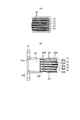
- FIG. 1 shows a heat exchanger according to an embodiment of the present invention, in which (a) is a side view of the heat exchanger, (b) is a front view of the heat exchanger, and (c) is a plan view of the heat exchanger.
- FIG. 2 shows a part of a heat exchanger according to an embodiment of the present invention, in which (a) is a cross-sectional view of a part of the heat exchanger, and (b) is a longitudinal cross-sectional view of a part of the heat exchanger.
- FIG. 3 is a plan view of a fin according to an embodiment of the present invention.
- FIG. 4 is a perspective view of a fin according to an embodiment of the present invention.
- FIG. 5 shows the fin which concerns on one Embodiment of this invention, (a) is an enlarged plan view of a fin, (b) is an enlarged front view of a fin, (c) is a top view of the protrusion piece of one segment.
- 6A and 6B show a protruding piece according to an embodiment of the present invention, wherein FIG. 6A is a cross-sectional view of the protruding piece, FIG. 6B is a front view seen from the upstream side of the forward protruding piece, and FIG. It is the front view seen from the downstream of the protrusion piece.
- FIG. 7 is a schematic plan view of a part of the fin according to the embodiment of the present invention.
- FIG. 8A and 8B show a fin according to an embodiment of the present invention, where FIG. 8A is a cross-sectional view taken along line A1-A1 of FIG. 7, and FIG. 8B is a cross-sectional view taken along line A2-A2 of FIG. 9A and 9B show a fin according to an embodiment of the present invention, in which FIG. 9A is a cross-sectional view along B1-B1 in FIG. 7, and FIG. 9B is a cross-sectional view along B2-B2 in FIG.
- FIG. 10 is a diagram illustrating the strength of the vortex formed by the protruding pieces according to the comparative example and the first and second embodiments.
- 11A and 11B are diagrams for explaining the first definition of the present invention, in which FIG.
- FIG. 11A is a perspective view of a protruding piece
- FIG. 11B is a change in the strength of a vortex when the forward tilt angle of the forward protruding piece is changed.
- FIG. FIGS. 12A and 12B are views for explaining Rule 2 of the present invention, in which FIG. 12A is a perspective view of a protruding piece, and FIG. 12B is a diagram showing a change in the strength of a vortex when the installation angle of a forward inclined protruding piece is changed.
- FIG. 13A and 13B are views for explaining the provision 3 of the present invention, in which FIG. 13A is a perspective view of a projecting piece, FIG. 13B is a front view of a forward tilting projecting piece, and FIG.
- FIGS. 15A and 15B are views for explaining the definition 4 of the present invention, in which FIG. 14A is a perspective view of a protruding piece, and FIG. 14B shows a change in the strength of a vortex when the width of a forward protruding piece is changed. It is a characteristic diagram.
- FIGS. 15A and 15B are views for explaining the provision 5 of the present invention, in which FIG. 15A is a perspective view of a protruding piece, and FIG. 15B shows a change in the strength of a vortex when the height of a forward protruding piece is changed.
- FIGS. 17A and 17B are views for explaining the definition 6 of the present invention, in which FIG. 16A is a perspective view of a protruding piece, and FIG. 16B is a vortex when the length of the other side of the forward inclined protruding piece is changed. It is a characteristic diagram which shows the change of intensity.
- FIGS. 17A and 17B are views for explaining the definition 7 of the present invention, where FIG. 17A is a perspective view of a protruding piece, and FIG. 17B is a vortex when the minimum interval between the forward and backward protruding pieces is changed.
- FIG. 18A and 18B are views for explaining the provision 8 of the present invention, in which FIG. 18A is a perspective view of a protruding piece, and FIG.
- FIGS. 19A and 19B are diagrams for explaining the definition 9 of the present invention, where FIG. 19A is a perspective view of a protruding piece, and FIG. 19B is a graph showing the strength of a vortex when the center position of the bottom side of a forward protruding piece is changed. It is a characteristic diagram which shows a change.
- 20A and 20B are views for explaining the provision 10 of the present invention, in which FIG. 20A is a front view of the protruding piece, and FIG. 20B is a vortex when the overlapping ratio of the forward and backward protruding pieces is changed. It is a characteristic diagram which shows the change of the intensity of.
- FIG. 21A and 21B are views for explaining the provision 11 of the present invention, in which FIG. 21A is a perspective view showing the relationship between the protruding piece and the segment, and FIG. 21B is a change in the strength of the vortex when the dimension of the segment is changed.
- FIG. 22A and 22B are diagrams for explaining the provision 12 of the present invention, in which FIG. 22A is a perspective view showing the relationship between the protruding piece and the segment, and FIG. 22B is a change in the strength of the vortex when the dimension of the segment is changed.
- FIG. 23A and 23B are views for explaining the definition 13 of the present invention, in which FIG. 23A is a perspective view showing the relationship between the protruding piece and the segment, and FIG.
- FIG. 23B is a change in the strength of the vortex when the dimension of the segment is changed.
- FIG. 24A and 24B are views for explaining the definition 14 of the present invention, in which FIG. 24A is a perspective view showing the relationship between the protruding piece and the segment, and FIG. 24B is a diagram in which the amount of displacement between the adjacent segments in the exhaust flow direction is changed. It is a characteristic diagram which shows the change of the strength of the vortex in the case.
- FIG. 25 is a partially cutaway front view of a prior art exhaust heat exchange device.
- FIG. 26 is a perspective view of a tube in the exhaust heat exchanger of FIG. 27 is a perspective view of fins in the exhaust heat exchange device of FIG.
- FIG. 28 is a perspective view of a protruding piece in the exhaust heat exchanger of FIG. 29 shows a projecting piece in the exhaust heat exchanger of FIG. 25, (a) is a view of the projecting piece seen from the direction C in FIG. 28, (b) is a plan view of the projecting piece, and (c) is a projecting piece. It is the figure which looked at the vortex
- FIG.1 and FIG.2 is a figure which shows the heat exchanger 1 which concerns on this embodiment.
- the heat exchanger 1 is, for example, an EGR cooler that cools the recirculated exhaust gas in an exhaust gas recirculation device that recirculates exhaust gas from an internal combustion engine to intake air.
- the heat exchanger 1 includes an outer case 10, a plurality of tubes 20 accommodated in the outer case 10, and a pair of tanks 30 disposed at both ends of the plurality of tubes 20, 40.
- These parts are formed of a material excellent in heat resistance and corrosion resistance (for example, stainless steel). These members are fixed to each other by, for example, brazing each other's contact points.
- the outer case 10 is provided with a cooling water inlet portion 11 and a cooling water outlet portion 12 for cooling water (cooling fluid).
- a cooling water passage 13 as a liquid passage is formed outside the tube 20 in the outer case 10. Specifically, the cooling water passage 13 is formed in a gap between the adjacent tubes 20 and a gap between the outermost tube 20 and the inner surface of the outer case 10.
- a plurality of tubes 20 are stacked on each other. Thereby, the exhaust passage 20A as the gas passage through which the exhaust gas as the gas flows and the cooling water passage 13 are alternately provided.
- each tube 20 Both ends of each tube 20 are open inside a pair of tanks 30 and 40.
- One tank 30 is provided with an inlet header 31 formed with an inlet 31a through which exhaust gas is introduced, and the other tank 40 is provided with an outlet header 41 formed with an outlet 41a through which exhaust gas is discharged. It has been.
- the tube 20 is formed of two flat members 20C.
- a bulging portion 20B is formed at both ends in the longitudinal direction of the flat member 20C.
- the bulging portion 20B is in contact with the adjacent tubes 20 in a state where the tubes 20 are stacked. Thereby, a gap serving as the cooling water passage 13 is formed between the adjacent tubes 20.
- An exhaust passage 20 ⁇ / b> A is formed inside the tube 20.
- Fins 21 are installed in the exhaust passage 20A, and the exhaust passage 20A is divided into a plurality of segments 22 by the fins 21, as shown in FIGS.
- the fin 21 is formed by a corrugated plate having a rectangular wave-shaped cross section in which horizontal walls 23 and vertical walls 24 are alternately arranged in a cross section perpendicular to the exhaust flow direction SD. Is formed.
- Each horizontal wall 23 is in close contact with the inner surface of the flat member 20C of the tube 20 (that is, the surface of the flow path wall that defines the cooling water passage 13).
- Each vertical wall 24 divides the exhaust passage 20 ⁇ / b> A into a plurality of segments 22.
- the fin 21 has a direction CD (hereinafter, orthogonal) in which the irregularities in the tube stacking direction PD formed by the horizontal wall 23 and the vertical wall 24 are orthogonal to the exhaust flow direction SD and the tube stacking direction PD.
- a plurality of concavo-convex patterns arranged along the direction CD) have a shape arranged in the exhaust flow direction SD while shifting (offset) the position in the orthogonal direction CD every predetermined length in the exhaust flow direction SD. That is, as shown in FIGS. 3 and 4, the segment 22 repeats irregularities in the direction CD orthogonal to the exhaust flow direction SD and the tube stacking direction PD, and alternates for every predetermined length along the exhaust flow direction SD.
- a plurality of offset shapes are arranged in the exhaust flow direction SD and the orthogonal direction CD.
- the segment 22 is formed by a plurality of inner surfaces (four surfaces including one inner surface of the tube 20 and three inner surfaces of the fins 21) along the exhaust flow direction SD.
- a plurality of protruding pieces 25 are formed by cutting and raising on the horizontal wall 23 constituting each segment 22 at intervals in the exhaust flow direction SD.
- the protruding piece 25 protrudes so as to obstruct the exhaust flow in the exhaust passage 20A.
- the projecting piece 25 has a forward tilt angle ⁇ 1 that is forwardly tilted upstream in the exhaust flow direction SD (an attitude in which the distal end side of the projecting piece is inclined upstream of the base end side).
- the forwardly inclined projecting piece 25A and the forwardly inclined projecting piece 25A are disposed downstream of the forwardly inclined projecting piece 25A, and are tilted backwards in the exhaust flow direction SD (the distal end side of the projecting piece is located downstream of the proximal end side).
- a rearwardly inclined protruding piece 25B disposed at a rearwardly inclined angle ⁇ 2.
- the forward inclination angle ⁇ 1 is an angle formed by the forward inclination protruding piece 25A and the horizontal wall 23 in a cross section parallel to the exhaust flow direction SD and perpendicular to the horizontal wall 23 (see, for example, FIG. 11).
- the backward inclination angle ⁇ 2 is an angle formed by the backward inclination protruding piece 25B and the horizontal wall 23 in a cross section parallel to the exhaust flow direction SD and perpendicular to the horizontal wall 23 (see, for example, FIG. 11).
- the forward inclined protruding piece 25A is farthest from the bottom side 26A located on the peripheral surface defining the exhaust passage 20A, the pair of left and right side sides 27A and 28A, and the bottom side 26A. It is formed in a trapezoidal shape including the top side 29A.
- the base 26A is disposed at an installation angle ⁇ 1 that is oblique to the orthogonal direction CD (so as to obliquely intersect the orthogonal direction CD).
- the installation angle ⁇ 1 is an angle formed by the base 26A with respect to the orthogonal direction CD (see, for example, FIG. 11).
- One side 27A is located upstream of the other side 28A in the exhaust flow direction SD.
- One side 27A is shorter than the other side 28A. In other words, the other side 28A is longer than the one side 27A.
- the angle of the one side 27A with respect to the base 26A (between the one side 27A and the base 26A).
- the angle formed a) is larger than the angle of the other side 28A with respect to the base 26A (the angle formed between the other side 28A and the base 26A) b.
- the angle a is set to 90 degrees or more
- the angle b is set to 90 degrees or less.
- the top side 29A is inclined with respect to the bottom side 26A so that the one side 27A side becomes lower in a front view (see FIG. 6B) from the downstream side in the exhaust flow direction SD.
- the forward inclined protruding pieces 25A are arranged in the same direction in each segment 22 adjacent to the orthogonal direction CD. Further, the forward inclined projecting pieces 25A are arranged in line symmetry with respect to the orthogonal direction CD in each segment 22 adjacent to the exhaust flow direction SD. That is, the position of one side 27A in the orthogonal direction CD is common between the segments 22 adjacent in the orthogonal direction CD, and is plane-symmetric between the segments 22 adjacent in the exhaust flow direction SD.
- the backward inclined protruding piece 25B is arranged point-symmetrically with the forward inclined protruding piece 25A in a front view from the tube stacking direction PD. That is, as shown in FIG.6 (c), the backward inclination protrusion piece 25B is formed in the trapezoid shape which consists of the base 26B, the left-right paired side 27B, 28B, and the top 29B.
- the bottom 26B of the rearwardly inclined protruding piece 25B is disposed at the same position as the bottom 26A of the forwardly inclined protruding piece 25A in a front view from the downstream side in the exhaust flow direction SD.
- one end of the bottom side 26B of the backward inclined protruding piece 25B and the other end of the bottom side 26A of the forward inclined protruding piece 25A are on a straight line L1 parallel to the exhaust flow direction SD.
- the other end of the bottom side 26B of the backward inclined protruding piece 25B and the one end of the bottom side 26A of the forward inclined protruding piece 25A are arranged on a straight line L2 parallel to the exhaust flow direction SD.
- the center (middle point) of the bottom 26A of the rearwardly inclined protruding piece 25B and the center (middle point) of the bottom 26B of the forwardly inclined protruding piece 25A are the center line C1 of the segment 22 in the width direction (orthogonal direction CD). Is placed on top.
- the size of the gap between the vertical wall 24 and each of the protruding pieces 25A and 25B (the size of the space through which the airflow passes) is the same. Therefore, the strength of the airflow S flowing around the sides 28A and 28B is the same, and the performance can be maintained.
- the base 26B is arranged at an installation angle ⁇ 2 that is oblique to the orthogonal direction CD (so as to obliquely intersect the orthogonal direction CD).
- the bottom side 26B is provided in parallel with the bottom side 26A of the forward inclined protruding piece 25A.
- the installation angle ⁇ 2 is an angle formed by the base 26B with respect to the orthogonal direction CD (see, for example, FIG. 11).
- One side 27B is located downstream of the other side 28B in the exhaust flow direction SD.
- One side 27B is shorter than the other side 28B. In other words, the other side 28B is longer than the one side 27B.
- the angle of the one side 27B with respect to the bottom 26B (between the one side 27B and the bottom 26B).
- the formed angle) a ′ is larger than the angle of the other side 28B with respect to the base 26B (the angle formed between the other side 28B and the base 26B) b ′.
- the angle a ′ is set to 90 degrees or more
- the angle b ′ is set to 90 degrees or less.
- the top side 29B is lower than the bottom side 26B so that one side 27B side is lower in a front view (see FIG. 6C) from the downstream side of the exhaust flow direction SD (or the direction toward the exhaust flow direction SD). It is inclined.
- the rearwardly inclined protruding pieces 25B are arranged in the same direction in each segment 22 adjacent to the orthogonal direction CD, as shown in FIGS. Further, the rearwardly protruding pieces 25B are arranged in line symmetry with respect to the orthogonal direction CD in each segment 22 adjacent to the exhaust flow direction SD. That is, the position of one side 27B in the orthogonal direction CD is common between the segments 22 adjacent in the orthogonal direction CD, and is plane-symmetric between the segments 22 adjacent in the exhaust flow direction SD.
- the exhaust discharged from the internal combustion engine flows through the exhaust passage 20 ⁇ / b> A in each tube 20. Cooling water flows through the cooling water passage 13 in the outer case 10.
- the exhaust gas and the cooling water exchange heat through the tubes 20 and the fins 21.
- the forward inclined protruding pieces 25A and the backward inclined protruding pieces 25B of the fins 21 disturb the flow of the exhaust gas in the exhaust passage 20A to promote heat exchange.
- the exhaust gas flowing through the exhaust passage 20A collides with the forward projecting protruding piece 25A in each segment 22A to 22D, and the flow is inhibited. For this reason, the segments 22A to 22D cannot be moved straight, and a low pressure region is formed immediately downstream (backward) of the forward projecting piece 25A.
- the shape of the forward inclined protruding piece 25A is a trapezoid (polygon more than a quadrangle), and the damming area (area) of the exhaust gas flow is large, so it is formed immediately downstream of the forward inclined protruding piece 25A.
- the pressure in the low pressure region is sufficiently lower than when the protruding piece has a triangular shape.
- the forwardly inclined projecting piece 25A is disposed in a forwardly tilted state on the upstream side in the exhaust flow direction SD, the flow of exhaust gas that travels beyond the apex 29A of the forwardly inclined protruding piece 25A The direction of the flow cannot be changed smoothly as in the case of the arrangement in the collapsed state. Therefore, the airflow of the exhaust gas is easily drawn into the low pressure region downstream of the forward inclined protruding piece 25A.
- the direction in which the airflow beyond the top side 29A of the forward inclined protruding piece 25A is drawn is the direction toward the circumferential surface on which the bottom side 26A is located, so that the top of the forward inclined protruding piece 25A is located downstream of the forward inclined protruding piece 25A.
- a strong transverse vortex R (see the segment 22A in FIG. 7) is formed by the airflow that has passed over the side 29A.
- the airflow that wraps around the left and right sides 27A, 28A of the forward inclined protruding piece 25A is also drawn into the low pressure region downstream of the forward inclined protruding piece 25A. Since the pressure in the low pressure region downstream of the forward projecting protrusion 25A is lower at the position of the other side 28A than the position of the one side 27A, the airflow is easily drawn by the other side 28A. In addition, since the angle a of the one side 27A with respect to the base 26A is larger than the angle b of the other side 28A with respect to the base 26A, more airflow S flows around on the other side 28A.
- the airflow S stronger than the airflow on the one side 27A side is drawn downstream of the forward inclined protruding piece 25A, and the transverse vortex flow R is swirled. Since the direction in which the airflow S is drawn is different from the direction in which the airflow exceeding the top side 29A is drawn, the swirl direction of the transverse vortex R is changed by the airflow S.
- the strong transverse vortex flow R formed by the airflow flowing over the top side 29A of the forward inclined protruding piece 25A is converted into a strong vertical vortex T1 by the airflow S flowing around the other side 28A.
- the longitudinal vortex T1 is a vortex that exists for a long period of time without being attenuated as early as the transverse vortex R, and in the segment 22A, as shown in FIG. 9A, from the upstream side in the exhaust flow direction SD. Look right.
- the vertical vortex flow T1 has its path changed by the rearward inclined protruding piece 25B, and the upper surface (the peripheral surface in which the protruding piece 25 is not provided in the segment 22A).
- the boundary layer (the inner surface of the tube 20 and the horizontal of the fins 21) formed in the vicinity of the peripheral surface that is lifted up and close to the one side 27B of the rear protruding piece 25B and defines the exhaust passage 20A. It flows while disturbing the exhaust stagnation layer such as the wall 23. For this reason, heat transfer can be greatly promoted by the longitudinal vortex T1, and the heat exchange rate can be improved.
- the longitudinal vortex T1 bounced up by the rearwardly inclined projecting piece 25B in the segment 22A follows the above-mentioned path, and enters a large amount into the segment 22C and also enters a small amount into the segment 22D.
- the longitudinal vortex U2 is generated by the above-described mechanism.
- the direction of rotation of the longitudinal vortex flow U2 is opposite to that of the longitudinal vortex flow T1 as the protruding pieces 25 in the segment 22C are arranged in line symmetry with respect to the protruding pieces 25 in the segment 22A (that is, FIG. 9).
- it is counterclockwise when viewed from the upstream side in the exhaust flow direction SD. Since the segment 22C is displaced (offset) from the segment 22A in the orthogonal direction CD, the segment 22C has a boundary between the vertical vortex T1 and the vertical vortex U2, as shown in FIG. 9B.
- the direction of the flow of the vertical vortex T1 and the direction of the flow of the vertical vortex U2 in the part (within the two-dot chain line) are the same.
- the shear rate between the two vertical vortex flows T1 and U2 is reduced, and the action of stopping the rotation of the vortex flow is reduced, so that the lifetime of the vertical vortex flow T1 and the vertical vortex flow U2 can be extended.
- the heat exchange rate can be further improved by maintaining the vortex for a long time.
- a small amount of the longitudinal vortex U1 generated in the segment 22B also enters the segment 22C.
- the longitudinal vortex flow U1 has the same rotational direction as that of the longitudinal vortex flow U2, and has the action of inducing the generation of the longitudinal vortex flow U2, so that a stronger longitudinal vortex flow U2 can be generated.
- the vertical vortex flow U1 that is reverse (left rotation) to the vertical vortex flow T1 is generated by the mechanism described above.
- the longitudinal vortex U1 enters a large amount into the segment 22D.
- the flow direction of the vertical vortex flow T2 and the flow direction of the vertical vortex flow U1 are the same. The life of the longitudinal vortex T2 and the longitudinal vortex U1 can be further increased.
- the longitudinal vortex T1 has the same rotational direction as that of the longitudinal vortex T2, and has the effect of inducing the generation of the longitudinal vortex T2, so that a stronger longitudinal vortex T2 can be generated.
- the forward inclined protruding piece 25A has a trapezoidal shape
- the bottom side 26A of the forward inclined protruding piece 25A is disposed at the installation angle ⁇ 1 that is inclined with respect to the orthogonal direction CD
- the bottom side of one side 27A The angle a with respect to 26A is larger than the angle b with respect to the bottom side 26A of the other side 28A.
- the strong transverse vortex R formed by the airflow flowing over the apex side 29A of the forward inclined protruding piece 25A is turned into the strong longitudinal vortex T1 (T2, U1) by the airflow S flowing around the other side 28A. , U2).
- the longitudinal vortex T1 is present for a long period of time without being attenuated at an early stage like the lateral vortex R, and its path is changed by the rearwardly inclined protruding piece 25B, and it is splashed upward. Since the longitudinal vortex T1 whose path has been changed flows while disturbing the boundary layer (exhaust stagnant layer) formed in the vicinity of the peripheral surface defining the exhaust passage 20A, heat transfer is greatly promoted and the heat exchange rate is improved. .
- the other side 28A is longer than the one side 27A, it is possible to generate a stronger lateral vortex R. Accordingly, the strength of converting the lateral vortex R into the longitudinal vortex T1 is increased. Increase.
- the top side 29A of the forward inclined projecting piece 25A is inclined with respect to the bottom side 26A so that the one side 27A side becomes lower in the front view from the exhaust flow direction SD, and the other side 28A. Is located downstream of one side 27A, the strength of converting the lateral vortex R into the vertical vortex T1 as compared to the case where the top 29A is parallel to the bottom 26A when viewed in the exhaust flow direction SD. Increases further.
- each segment 22 arranged in the exhaust flow direction SD and the orthogonal direction CD is provided with the forward inclined protruding piece 25A and the backward inclined protruding piece 25B.
- the stagnant layer In addition to the stagnant layer), it also hits the vertical wall 24 on the one side 27B side, and the longitudinal vortex T1 can greatly promote heat transfer.
- the forward inclined projecting pieces 25A are arranged in the same direction in each segment 22 adjacent to the orthogonal direction CD, so that the longitudinal vortex T1, T2 (right rotation) and the longitudinal vortex U1, U2 (left) Rotation) can be generated, and the action of stopping the rotation of the vortex flow by suppressing the shear rate between the vortex flows in each segment 22 can be reduced, and the life of the vortex can be extended.
- the forward inclined projecting pieces 25A are arranged line-symmetrically with respect to the orthogonal direction CD in each segment 22 adjacent to the exhaust flow direction SD.
- the shear rate becomes low, the action of stopping the rotation with respect to each other's vortex flow can be reduced, and the life of the vortex can be further increased.
- the angle a with respect to the base 26A of one side 27A is 90 degrees or more, and the angle b with respect to the base 26A of the other side 28A is set to 90 degrees or less.
- the interval between 28A and the vertical wall 24 tends to be substantially the same with respect to the exhaust flow direction SD. Therefore, an airflow S having substantially the same strength is generated from the top side 29A to the bottom side 26A of the forward inclined protruding piece 25A, and the horizontal vortex R can be strongly converted by the vertical vortex T1 by the airflow S.
- the backward inclination protrusion piece 25B is arrange
- the quality of the heat exchanger 1 can be stabilized without lowering, without the risk of erroneous assembly during manufacture.
- the bottom side 26B of the backward inclined protruding piece 25B is disposed at the same position as the bottom side 26A of the forward inclined protruding piece 25A in the front view from the exhaust flow direction SD. Even if the fins 21 are arranged upside down, the heat exchange efficiency does not decrease, there is no risk of erroneous assembly during manufacture, and the quality of the heat exchanger 1 is stabilized.
- FIG. 10 shows the strength of the vortex generated by the protruding piece according to the comparative example and Examples 1 and 2.
- the protruding piece according to the comparative example is a trapezoid (isosceles trapezoid) in which the top side is parallel to the bottom side and the angles of the left and right side sides are equal to the bottom side when viewed from the upstream side in the exhaust flow direction. It is formed in a shape.
- the protruding piece 25 according to the first embodiment has an angle of one side 27A with respect to the base 26A of 60 degrees and an angle of the other side 28B with respect to the base 26A. It is 90 degrees, and the top side 29A is formed in a trapezoidal shape parallel to the bottom side 26A.
- the protruding piece 25 according to Example 2 has been described in the above-described embodiment.
- the strength of the vortex generated by the protruding piece according to the comparative example and the first and second embodiments is measured, and the strength of the vortex generated by the protruding piece according to the first embodiment is set to “1 (reference value)”. It was compared with the strength of the vortex produced by the protruding piece according to Example and Example 2. As shown in FIG. 10, the vortices according to Examples 1 and 2 are stronger than the vortex according to the comparative example, and it was proved that a stronger eddy current can be generated by the above-described vortex generation mechanism.
- the strength of the vortex is, for example, a certain channel cross section when the coordinate of the exhaust flow direction SD with the origin at the installation position of the protruding piece (vortex generating portion) is x and the height of the protruding piece is h.
- FIG. 11A is a perspective view of the projecting piece 25
- FIG. 11B is a characteristic diagram showing a change in the strength of the vortex when the forward tilt angle ⁇ 1 of the forward tilted projecting piece 25A is changed. It is.
- the installation angle ⁇ 1 is 45 degrees
- the angle a of the one side 27A with respect to the base 26A is 135 degrees
- the angle b of the other side 28A with respect to the base 26A is 45 degrees
- the forward tilt angle of the forward tilting protruding piece 25A ⁇ 1 was changed.
- the forward inclination angle ⁇ 1 of the forward inclined protrusion 25A is preferably 40 to 50 degrees with respect to the exhaust flow direction SD.
- the vortex strength becomes “1.25” or more with respect to the first embodiment (vortex strength “1.00”).
- FIG. 12A is a perspective view of the protruding piece 25
- FIG. 12B is a characteristic diagram showing a change in the strength of the vortex when the installation angle ⁇ 1 of the forward inclined protruding piece 25A is changed. is there.
- the vortex (vortex) stronger than that in the first embodiment is set by setting the installation angle ⁇ 1 of the forward inclined protruding piece 25A to 10 to 60 degrees with respect to the exhaust flow direction SD. Strength of “1.1” or more) can be obtained.
- the installation angle ⁇ 1 of the forward inclined protruding piece 25A is preferably 35 to 60 degrees with respect to the exhaust flow direction SD.
- the vortex strength becomes “1.25” or more with respect to the first embodiment (vortex strength “1.00”).
- FIG. 13A is a perspective view of the protruding piece 25
- FIG. 13B is a front view of the forward inclined protruding piece 25A
- FIG. 13C is a side 27A of the forward inclined protruding piece 25A.
- the forward tilt angle ⁇ 1 is 45 degrees
- the installation angle ⁇ 1 is 45 degrees
- the angle a of one side 27A with respect to the base 26A is 135 degrees
- the angle b of the other side 28A with respect to the base 26A is 45 degrees.
- the curvature radius R1 of the corner formed between the side 27A and the apex 29A of the inclined projecting piece 25A and the curvature radius R2 of the corner formed between the side 28A and the apex 29A were changed.
- an arc shape (R shape) is provided at the corner portion of one side 27A and the top side 29A of the forward inclined protruding piece 25A in order to extend the life of the blade. Is attached.
- the curvature radius R1 of the corner formed between the side 27A and the apex 29A of the forward inclined protrusion 25A and the curvature radius R2 of the corner formed between the side 28A and the apex 29A are forward tilted.
- the height is preferably 5 to 55% with respect to the height H25 from the bottom side 26A of the protruding piece 25A to the highest vertex of the top side 29A.
- the vortex strength is 1.25 or more with respect to Example 1 (vortex strength “1.00”).
- FIG. 14A is a perspective view of the projecting piece 25
- FIG. 14B is a characteristic diagram showing changes in the strength of the vortex when the width W25 of the forward tilting projecting piece 25A is changed. .
- the ratio of the width W25 of the forward inclined protruding piece 25A in the orthogonal direction CD to the width W22 of the exhaust passage 20A (segment 22) was changed.
- the other conditions of the forward inclined protruding piece 25 ⁇ / b> A are the same as defined 3.
- the ratio of the width W25 of the forward inclined protruding piece 25A to the width W22 of the exhaust passage 20A is set to 40 to 80%. Strong vortices (vortex strength “1.1” or more) can be obtained.
- the ratio of the width W25 of the forward inclined protruding piece 25A to the width W22 of the segment 22 is preferably 50 to 75%.
- the vortex strength becomes “1.25” or more with respect to the first embodiment (vortex strength “1.00”).
- FIG. 15A is a perspective view of the projecting piece 25
- FIG. 15B is a characteristic diagram showing a change in the strength of the vortex when the height H25 of the forward tilting projecting piece 25A is changed. is there.
- the ratio of the height H25 of the forward inclined protruding piece 25A to the height H22 of the exhaust passage 20A (segment 22) was changed.
- the other conditions of the forward inclined protruding piece 25 ⁇ / b> A are the same as defined 3.
- the ratio of the height H25 of the forward inclined protruding piece 25A to the height H22 of the exhaust passage 20A (segment 22) is set to 25 to 45%.
- a vortex stronger than 1 can be obtained.
- the ratio of the height H25 of the forward inclined protruding piece 25A to the height H22 of the exhaust passage 20A (segment 22) is preferably 33 to 42%.
- the vortex strength becomes “1.25” or more with respect to the first embodiment (vortex strength “1.00”).
- FIG. 16A is a perspective view of the protruding piece 25, and FIG. 16B is a change in the strength of the vortex when the length L28 of the other side 28A of the forward inclined protruding piece 25A is changed.
- FIG. 16B is a change in the strength of the vortex when the length L28 of the other side 28A of the forward inclined protruding piece 25A is changed.
- the ratio of the length L28 in the exhaust flow direction SD of the other side 28A of the forward inclined protruding piece 25A to the length L22 along the exhaust flow direction SD of the segment 22 was changed.
- the other conditions of the forward inclined protruding piece 25 ⁇ / b> A are the same as defined 3.
- the length L28 of the forward inclined protruding piece 25A is preferably 15 to 28% with respect to the length L22 of the segment 22.
- the vortex strength becomes “1.25” or more with respect to the first embodiment (vortex strength “1.00”).
- FIG. 17 (a) is a perspective view of the protruding piece 25, and FIG. 17 (b) shows the strength of the vortex when the minimum distance D between the forward inclined protruding piece 25A and the backward inclined protruding piece 25B is changed. It is a characteristic diagram which shows a change.
- the minimum distance D between the forward inclined protruding piece 25A and the backward inclined protruding piece 25B was changed.
- the other conditions of the forward inclined protruding piece 25 ⁇ / b> A are the same as defined 3.
- the minimum distance D between the forward inclined protruding piece 25A and the backward inclined protruding piece 25B is set along the exhaust flow direction SD of the other side 28A of the forward inclined protruding piece 25A.
- the minimum distance D between the forward inclined protruding piece 25A and the backward inclined protruding piece 25B is preferably 36 to 65% with respect to the length L28 of the other side 28A of the forward inclined protruding piece 25A.
- the vortex strength becomes “1.25” or more with respect to the first embodiment (vortex strength “1.00”).
- FIG. 18A is a perspective view of the protruding piece 25, and FIG. 18B is a characteristic showing a change in the strength of the vortex when the central position c of the bottom 26A of the forward inclined protruding piece 25A is changed.
- FIG. 18B is a characteristic showing a change in the strength of the vortex when the central position c of the bottom 26A of the forward inclined protruding piece 25A is changed.
- the center position c of the bottom side 26A of the forward inclined protruding piece 25A is set to 30 from the upstream side of the segment 22 with respect to the length L22 of the exhaust flow direction SD of the segment 22.
- a stronger vortex vortex strength “1.17” or more) than in the first embodiment can be obtained.
- the center position c of the bottom side 26A of the forward inclined protruding piece 25A is preferably provided within a range z of 35 to 65% from the upstream side of the segment 22 with respect to the length L22 of the segment 22 in the exhaust flow direction SD. .
- the vortex strength becomes “1.25” or more with respect to the first embodiment (vortex strength “1.00”).
- FIG. 19A is a perspective view of the protruding piece 25, and FIG. 19B is a characteristic showing a change in the strength of the vortex when the central position c of the bottom 26A of the forward inclined protruding piece 25A is changed.
- FIG. 19B is a characteristic showing a change in the strength of the vortex when the central position c of the bottom 26A of the forward inclined protruding piece 25A is changed.
- the center position c of the bottom side 26A of the forward inclined projecting piece 25A is based on the center in the width direction with respect to the width W22 of the segment 22 in the orthogonal direction CD (50%). Is preferably in the range of 25 to 70%. Thereby, a vortex (vortex strength “1.25” or more) stronger than Example 1 (vortex strength “1.00”) can be obtained.
- the center position c of the base 26A of the forward inclined protruding piece 25A is preferably in the range of 40 to 60% with respect to the width W22 of the segment 22 with respect to the center in the width direction.
- the vortex strength becomes “1.31” or more with respect to Example 1 (vortex strength “1.00”).
- FIG. 20A is a front view of the protruding piece 25
- FIG. 20B is a change in the strength of the vortex when the overlapping rate of the forward inclined protruding piece 25A and the backward inclined protruding piece 25B is changed.
- FIG. 20A is a front view of the protruding piece 25
- FIG. 20B is a change in the strength of the vortex when the overlapping rate of the forward inclined protruding piece 25A and the backward inclined protruding piece 25B is changed.
- the overlapping ratio of the forward inclined protruding piece 25A and the backward inclined protruding piece 25B that is, the overlapping area of the projected area of the forward inclined protruding piece 25A and the projected area of the backward inclined protruding piece 25B in the projection in the exhaust flow direction SD. Changed the ratio of the forward inclined protruding piece 25A in the projection area.
- the other conditions of the forward inclined protruding piece 25 ⁇ / b> A are the same as defined 3.
- the overlap ratio between the forward inclined protruding piece 25A and the backward inclined protruding piece 25B is set to 50% or more, so that the first embodiment (vortex strength “1.00” is obtained). )) Can be obtained (vortex strength “1.10” or more).
- the forward inclined protruding piece 25A has an overlapping rate of the forward inclined protruding piece 25A and the backward inclined protruding piece 25B of 70% or more.
- the vortex strength becomes “1.25” or more with respect to the first embodiment (vortex strength “1.00”).
- FIG. 21A is a perspective view of the protruding piece 25 and the segment 22, and FIG. 21B is a characteristic diagram showing changes in the strength of the vortex when the dimensions of the segment 22 are changed.
- the height H22 of the segment 22 in the tube stacking direction PD and the length L22 of the segment 22 in the exhaust flow direction SD were changed.
- the conditions of the protruding piece 25 other than the configuration of the segment 22 are the same as those in the regulation 3.
- the height H22 of the segment 22 is preferably set to 22 to 38% with respect to the length L22 of the segment 22.
- the vortex strength becomes “1.25” or more with respect to the first embodiment (vortex strength “1.00”).
- FIG. 22A is a perspective view showing a part of the projecting piece 25 and the segment 22, and
- FIG. 22B is a characteristic diagram showing a change in the strength of the vortex when the segment 22 is changed. is there.
- the width W22 of the segment 22 in the orthogonal direction CD and the length L22 of the segment 22 in the exhaust flow direction SD were changed.
- the conditions of the protruding piece 25 other than the configuration of the segment 22 are the same as those in the regulation 3.
- the width W22 of the segment 22 is preferably set to 15 to 40% with respect to the length L22 of the segment 22.
- the vortex strength becomes “1.25” or more with respect to the first embodiment (vortex strength “1.00”).
- FIG. 23A is a perspective view of the protruding piece 25 and the segment 22, and FIG. 23B is a characteristic diagram showing changes in the strength of the vortex when the segment 22 is changed.
- the width W22 and height H22 of the segment 22 were changed.
- the conditions of the protruding piece 25 other than the configuration of the segment 22 are the same as those in the regulation 3.
- the width W22 of the segment 22 is preferably set to 82 to 112% with respect to the height H22 of the segment 22.
- the vortex strength becomes “1.25” or more with respect to the first embodiment (vortex strength “1.00”).
- FIG. 24A is a perspective view of the protruding piece 25 and the segment 22, and FIG. 24B shows the shift amount between the segments 22 adjacent to the exhaust flow direction SD (shift amount of the position in the orthogonal direction CD). It is a characteristic diagram which shows the change of the strength of the vortex at the time of changing.
- the center line CL of each segment 22 is segmented with respect to the center line CL of the segment 22 adjacent to the exhaust flow direction SD (for example, the downstream segment 22). It is preferable to dispose them by 30 to 70% of the width W22 of the 22 orthogonal CDs. That is, it is preferable to set the distance between the center lines CL of the two segments 22 adjacent in the exhaust flow direction SD to 30 to 70% of the width W22 of the segment 22. As a result, the vortex strength becomes “1.25” or more with respect to the first embodiment (vortex strength “1.00”).
- the center line CL of each segment 22 is 35 with a width W22 of the segment 22 with respect to the segment 22 adjacent to the exhaust flow direction SD (for example, the downstream segment 22) with respect to the center line CL of each segment 22. It is preferable to dispose by ⁇ 65%. Thereby, the strength of the vortex becomes “1.30” or more with respect to the comparative example (vortex strength “1.00”).
- the embodiment of the present invention can be modified as follows.
- the heat exchanger 1 has been described as an EGR cooler, the heat exchanger 1 is not limited to this, and a heat exchanger (for example, a supply air cooler (CAC cooler) that exchanges heat between gas and refrigerant is not limited thereto. ) Or an exhaust heat recovery device).
- a heat exchanger for example, a supply air cooler (CAC cooler) that exchanges heat between gas and refrigerant is not limited thereto.
- CAC cooler supply air cooler
- exhaust heat recovery device for example, a heat exchanger that exchanges heat between gas and refrigerant is not limited thereto.
- protruding piece 25 has been described as being formed on the horizontal wall 23 of the segment 22, but is not limited thereto, and may be formed on the vertical wall 24 of the segment 22.
- the forward inclined projecting piece 25A has been described as having a trapezoidal shape, but is not limited to this, and is not limited to this. If it is.
- the polygon more than a rectangle is a plane figure enclosed by four or more line segments, such as a rectangle, a pentagon, and a hexagon.
- the backward inclined protruding piece 25B has been described as having a trapezoidal shape, but is not limited to this, and is not limited to this. If it is.
- one side 27A of the forward inclined protruding piece 25A has been described as being shorter than the other side 28A, the present invention is not limited to this. For example, it is the same as or slightly shorter than the other side 28A. It may be a thing.
- top side 29A of the forward inclined protruding piece 25A has been described as being inclined with respect to the bottom side 26A, it is not limited to this and may be provided in parallel with the bottom side 26A.
- segment 22 has been described as being formed in an offset shape, the present invention is not limited to this, and the segment 22 may simply have an uneven shape in the orthogonal direction CD.
- the angle a with respect to the base 26A of one side 27A of the forward inclined protruding piece 25A is 90 degrees or more
- the angle b with respect to the base 26A of the other side 28A is set to 90 degrees or less.
- the present invention is not limited to this, and may be set any number of times as long as the angle a is larger than the angle b.
- the forward inclined protruding piece 25A has been described as being arranged in the same direction in each segment 22 adjacent to the orthogonal direction CD, but is not limited to this, and in each segment 22 adjacent to the orthogonal direction CD, It may be arranged in line symmetry.
- the forward inclined projecting piece 25A has been described as being arranged line-symmetrically with respect to the orthogonal direction CD in each segment 22 adjacent to the exhaust flow direction SD, but the present invention is not limited to this, and the exhaust flow direction is not limited thereto.
- the segments 22 adjacent to the SD may be arranged in the same direction.
- the backward inclined protruding piece 25B has been described as being arranged point-symmetrically with the forward inclined protruding piece 25A with respect to the direction CD orthogonal to the exhaust flow direction SD and the tube stacking direction PD. Instead, it may be axisymmetric or asymmetric with the forward inclined protruding piece 25A.
Landscapes
- Engineering & Computer Science (AREA)
- Physics & Mathematics (AREA)
- Mechanical Engineering (AREA)
- General Engineering & Computer Science (AREA)
- Thermal Sciences (AREA)
- Geometry (AREA)
- Chemical & Material Sciences (AREA)
- Combustion & Propulsion (AREA)
- Heat-Exchange Devices With Radiators And Conduit Assemblies (AREA)
Abstract
Description
まず、本実施形態に係る熱交換器1の構成について、図面を参照しながら説明する。図1及び図2は、本実施形態に係る熱交換器1を示す図である。熱交換器1は、例えば、内燃機関の排気を吸気に還流させる排気再循環装置において、還流される排気を冷却するEGRクーラである。 <Heat exchanger>
First, the configuration of the
チューブ20の構成について、図面を参照しながら説明する。図3~図6は、本実施形態に係るチューブ20を示す図である。 <Tube>
The configuration of the
前傾突出片25Aは、図6(b)に示すように、排気通路20Aを画成する周面上に位置する底辺26Aと、左右一対の側辺27A,28Aと、底辺26Aから最も離れた頂辺29Aとから成る台形形状に形成されている。 <Forward tilting protruding piece>
As shown in FIG. 6B, the forward inclined protruding
後傾突出片25Bは、チューブ積層方向PDからの正面視において、前傾突出片25Aと点対称に配置されている。つまり、後傾突出片25Bは、図6(c)に示すように、底辺26Bと、左右一対の側辺27B,28Bと、頂辺29Bとから成る台形形状に形成されている。 <Backward tilting protruding piece>
The backward inclined protruding
図7~図9に基づき、熱交換器1の熱交換の促進作用について説明する。なお、図7~図9に関する説明では、図7の左上のセグメント22を「セグメント22A」とし、図7の左下のセグメント22を「セグメント22B」とし、図7の右上のセグメント22を「セグメント22C」とし、図7の右下のセグメント22を「セグメント22D」とする。 <Acceleration of heat exchange>
Based on FIGS. 7 to 9, the heat exchange promoting action of the
以上説明した本実施形態では、前傾突出片25Aが台形であり、前傾突出片25Aの底辺26Aが直交方向CDに対し斜め向きとなる設置角度β1で配置され、一方の側辺27Aの底辺26Aに対する角度aが他方の側辺28Aの底辺26Aに対する角度bよりも大きい。これにより、前傾突出片25Aの頂辺29Aを越えて流れた気流によって形成された強い横渦流Rは、他方の側辺28Aを回り込んで流れた気流Sによって強い縦渦流T1(T2,U1,U2)に変換される。この縦渦流T1は、横渦流Rのように早期に減衰せずに長期に亘って存在し、後傾突出片25Bで進路を変更されて上方に跳ね上げられる。進路を変更された縦渦流T1は排気通路20Aを画成する周面近傍に形成された境界層(排気停滞層)を乱しつつ流れるため、熱伝達が大きく促進され、熱交換率が向上する。 <Action and effect>
In the present embodiment described above, the forward inclined protruding
次に、突出片25(前傾突出片25A及び後傾突出片25B)によって生成される渦の強さを評価した。図10は、比較例及び実施例1,2に係る突出片によって生成された渦の強さを示す。 <Comparison evaluation>
Next, the strength of vortices generated by the protruding pieces 25 (the forward inclined protruding
次に、突出片25やセグメント22の様々な規定(突出片25やセグメント22の形状や寸法を規定するパラメータ)について説明する。なお、以下に説明する各規定の評価は、実施例1に係る突出片25によって生成された渦の強さを基準「1」としたものである。 <Provision of protruding pieces and segments>
Next, various definitions of the protruding
まず、突出片25の規定1について、図11を参照しながら説明する。図11(a)は、突出片25の斜視図であり、図11(b)は、前傾突出片25Aの前傾角度α1を変化させた場合の渦の強さの変化を示す特性線図である。 (Regulation 1)
First, the
次に、突出片25の規定2について、図12を参照しながら説明する。図12(a)は、突出片25の斜視図であり、図12(b)は、前傾突出片25Aの設置角度β1を変化させた場合の渦の強さの変化を示す特性線図である。 (Regulation 2)
Next, the definition 2 of the protruding
次に、突出片25の規定3について、図13を参照しながら説明する。図13(a)は、突出片25の斜視図であり、図13(b)は、前傾突出片25Aの正面図であり、図13(c)は、前傾突出片25Aの側辺27Aと頂辺29Aとの間に形成される角部の曲率半径R1や側辺28Aと頂辺29Aと間に形成される角部の曲率半径R2を変化させた場合の渦の強さの変化を示す特性線図である。 (Regulation 3)
Next, the definition 3 of the protruding
次に、突出片25の規定4について、図14を参照しながら説明する。図14(a)は、突出片25の斜視図であり、図14(b)は、前傾突出片25Aの幅W25を変化させた場合の渦の強さの変化を示す特性線図である。 (Regulation 4)
Next, the definition 4 of the protruding
次に、突出片25の規定5について、図15を参照しながら説明する。図15(a)は、突出片25の斜視図であり、図15(b)は、前傾突出片25Aの高さH25を変化させた場合の渦の強さの変化を示す特性線図である。 (Regulation 5)
Next, the definition 5 of the protruding
次に、突出片25の規定6について、図16を参照しながら説明する。図16(a)は、突出片25の斜視図であり、図16(b)は、前傾突出片25Aの他方の側辺28Aの長さL28を変化させた場合の渦の強さの変化を示す特性線図である。 (Regulation 6)
Next, the definition 6 of the protruding
次に、突出片25の規定7について、図17を参照しながら説明する。図17(a)は、突出片25の斜視図であり、図17(b)は、前傾突出片25Aと後傾突出片25Bとの最小間隔Dを変化させた場合の渦の強さの変化を示す特性線図である。 (Regulation 7)
Next, the definition 7 of the protruding
次に、突出片25の規定8について、図18を参照しながら説明する。図18(a)は、突出片25の斜視図であり、図18(b)は、前傾突出片25Aの底辺26Aの中央位置cを変化させた場合の渦の強さの変化を示す特性線図である。 (Regulation 8)
Next, the definition 8 of the protruding
次に、突出片25の規定9について、図19を参照しながら説明する。図19(a)は、突出片25の斜視図であり、図19(b)は、前傾突出片25Aの底辺26Aの中央位置cを変化させた場合の渦の強さの変化を示す特性線図である。 (Regulation 9)
Next, the definition 9 of the protruding
次に、突出片25の規定10について、図20を参照しながら説明する。図20(a)は、突出片25の正面図であり、図20(b)は、前傾突出片25Aと後傾突出片25Bとの重なり率を変化させた場合の渦の強さの変化を示す特性線図である。 (Regulation 10)
Next, the
次に、セグメント22の規定11について、図21を参照しながら説明する。図21(a)は、突出片25及びセグメント22の斜視図であり、図21(b)は、セグメント22の寸法を変化させた場合の渦の強さの変化を示す特性線図である。 (Regulation 11)
Next, the
次に、セグメント22の規定12について、図22を参照しながら説明する。図22(a)は、突出片25及びセグメント22の一部を示す斜視図であり、図22(b)は、セグメント22を変化させた場合の渦の強さの変化を示す特性線図である。 (Regulation 12)
Next, the
次に、セグメント22の規定13について、図23を参照しながら説明する。図23(a)は、突出片25及びセグメント22の斜視図であり、図23(b)は、セグメント22を変化させた場合の渦の強さの変化を示す特性線図である。 (Regulation 13)
Next, the
次に、セグメント22の規定14について、図24を参照しながら説明する。図24(a)は、突出片25及びセグメント22の斜視図であり、図24(b)は、排気流れ方向SDに隣接したセグメント22間のずれ量(直交方向CDの位置のずれ量)を変化させた場合の渦の強さの変化を示す特性線図である。 (Regulation 14)
Next, the definition 14 of the
上述したように、本発明の実施形態を通じて本発明の内容を開示したが、この開示の一部をなす論述及び図面は、本発明を限定するものであると理解すべきではない。この開示から当業者には様々な代替実施の形態、実施例及び運用技術が明らかとなる。 (Other embodiments)
Although the contents of the present invention have been disclosed through the embodiments of the present invention as described above, it should not be understood that the descriptions and drawings constituting a part of this disclosure limit the present invention. From this disclosure, various alternative embodiments, examples, and operational techniques will be apparent to those skilled in the art.
10 外装ケース
11 冷却水入口部
12 冷却水出口部
13 冷却水通路(液体通路)
20 チューブ
20A 排気通路(気体通路)
21 フィン
22(22A~22D) セグメント
25 突出片
25A 前傾突出片
26A 底辺
27A 一方の側辺
28A 他方の側辺
29A 頂辺
25B 後傾突出片
26B 底辺
27B 他方の側辺
28B 側辺
29B 頂辺 DESCRIPTION OF
20
21 Fin 22 (22A to 22D)
Claims (12)
- 気体が流れる気体通路に、気体流れ方向の上流側に前倒れ状態となる前傾角度α1で配置された前傾突出片と、前記前傾突出片の下流に配置され、前記気体流れ方向の下流側に後倒れ状態となる後傾角度で配置された後傾突出片とを設け、
前記前傾突出片は、前記気体通路の周面に接する底辺と左右一対の側辺とを有する四角形以上の多角形であり、
前記前傾突出片の前記底辺は、前記気体流れ方向に直交する方向に対し斜め向きとなる設置角度で配置され、
前記前傾突出片の気体流れ方向の上流側に位置する一方の前記側辺の前記底辺に対する角度は、前記前傾突出片の前記気体流れ方向の下流側に位置する他方の前記側辺の前記底辺に対する角度よりも大きいことを特徴とする熱交換器。 In the gas passage through which the gas flows, a forwardly inclined protruding piece arranged at a forward inclination angle α1 that is in a forwardly inclined state on the upstream side in the gas flow direction, and arranged downstream of the forwardly inclined protruding piece, downstream in the gas flow direction A rearwardly inclined protruding piece arranged at a rearward inclination angle that is in a rearward tilted state is provided on the side,
The forwardly inclined projecting piece is a quadrilateral or more polygon having a bottom and a pair of left and right sides contacting the peripheral surface of the gas passage,
The bottom side of the forward inclined protruding piece is disposed at an installation angle that is oblique with respect to a direction orthogonal to the gas flow direction,
The angle of the one side located on the upstream side in the gas flow direction of the forward sloping protrusion piece with respect to the base is the angle of the other side located on the downstream side in the gas flow direction of the front leaning protrusion piece. A heat exchanger characterized by being larger than the angle with respect to the bottom. - 請求項1に記載の熱交換器であって、
他方の前記側辺は、一方の前記側辺よりも長いことを特徴とする熱交換器。 The heat exchanger according to claim 1,
2. The heat exchanger according to claim 1, wherein the other side is longer than the one side. - 請求項1又は請求項2に記載の熱交換器であって、
前記前傾突出片の前記底辺から最も離れた頂辺は、前記気体流れ方向からの正面視において一方の前記側辺側が低くなるように前記底辺に対して傾斜することを特徴とする熱交換器。 The heat exchanger according to claim 1 or 2,
The top of the forward inclined protruding piece that is farthest from the bottom is inclined with respect to the bottom so that one of the sides is lower in a front view from the gas flow direction. . - 請求項1乃至請求項3の何れかに記載の熱交換器であって、
前記気体通路は、前記気体流れ方向に直交する方向に凹凸状を繰り返すとともに、前記気体流れ方向に沿って所定長さ毎に交互にずらしたオフセット形状に形成されることによって、前記気体流れ方向及び前記直交方向に配置される複数のセグメントに分割され、
前記前傾突出片及び前記後傾突出片は、前記各セグメントに設けられることを特徴とする熱交換器。 A heat exchanger according to any one of claims 1 to 3,
The gas passage has an uneven shape in a direction orthogonal to the gas flow direction, and is formed in an offset shape that is alternately shifted every predetermined length along the gas flow direction. Divided into a plurality of segments arranged in the orthogonal direction,
The heat exchanger according to claim 1, wherein the forward inclined protruding piece and the backward inclined protruding piece are provided in each segment. - 請求項4に記載の熱交換器であって、
前記前傾突出片は、液体が流れる液体通路に密接する面に形成され、気体流れ方向に直交する方向に隣接した前記各セグメントにおいて同一向きに配置されることを特徴とする熱交換器。 The heat exchanger according to claim 4,
The forwardly inclined projecting piece is formed on a surface in close contact with a liquid passage through which a liquid flows, and is disposed in the same direction in each segment adjacent to a direction orthogonal to the gas flow direction. - 請求項4又は請求項5に記載の熱交換器であって、
前記前傾突出片は、液体が流れる液体通路に密接する面に形成され、気体流れ方向に隣接した前記各セグメントにおいて前記気体流れ方向に直交する方向に対して線対称に配置されることを特徴とする熱交換器。 The heat exchanger according to claim 4 or 5, wherein
The forward inclined protruding piece is formed on a surface in close contact with a liquid passage through which a liquid flows, and is arranged in line symmetry with respect to a direction perpendicular to the gas flow direction in each segment adjacent to the gas flow direction. Heat exchanger. - 請求項1乃至請求項6の何れかに記載の熱交換器であって、
一方の前記側辺の前記底辺に対する角度は、90度以上であり、他方の前記側辺の前記底辺に対する角度は、90度以下であることを特徴とする熱交換器。 The heat exchanger according to any one of claims 1 to 6,
An angle of one side to the bottom is 90 degrees or more, and an angle of the other side to the bottom is 90 degrees or less. - 請求項1乃至請求項7の何れかに記載の熱交換器であって、
前記前傾突出片の前記前傾角度は、前記気体流れ方向に対して40~50度であることを特徴とする熱交換器。 A heat exchanger according to any one of claims 1 to 7,
The heat exchanger according to claim 1, wherein the forward inclined angle of the forward inclined protruding piece is 40 to 50 degrees with respect to the gas flow direction. - 請求項1乃至請求項8の何れかに記載の熱交換器であって、
前記前傾突出片の前記設置角度は、前記気体流れ方向に対して35~60度であること特徴とする熱交換器。 A heat exchanger according to any one of claims 1 to 8,
The heat exchanger according to claim 1, wherein the installation angle of the forward projecting protruding piece is 35 to 60 degrees with respect to the gas flow direction. - 請求項1乃至請求項9の何れかに記載の熱交換器であって、
前記後傾突出片の底辺は、排気流れ方向SDからの正面視において、前記前傾突出片の底辺と同じ位置に配置されることを特徴とする熱交換器。 A heat exchanger according to any one of claims 1 to 9,
The heat exchanger according to claim 1, wherein a bottom side of the backward inclined protruding piece is disposed at the same position as a bottom side of the forward inclined protruding piece in a front view from the exhaust flow direction SD. - 請求項1乃至請求項10の何れかに記載の熱交換器であって、
前記後傾突出片は、前記気体通路の周面に接する底辺と左右一対の側辺とを有する四角形以上の多角形であり、
前記前傾突出片の前記底辺は、前記後傾突出片の前記底辺と平行に設けられることを特徴とする熱交換器。 The heat exchanger according to any one of claims 1 to 10,
The rearwardly inclined protruding piece is a quadrilateral or more polygon having a bottom side in contact with the peripheral surface of the gas passage and a pair of left and right sides.
The heat exchanger according to claim 1, wherein the bottom side of the forward inclined protruding piece is provided in parallel with the bottom side of the backward inclined protruding piece. - 請求項1乃至請求項11の何れかに記載の熱交換器であって、
前記後傾突出片は、前記前傾突出片と点対称に配置されることを特徴とする熱交換器。 A heat exchanger according to any one of claims 1 to 11,
The heat exchanger according to claim 1, wherein the backward inclined protruding piece is arranged point-symmetrically with the forward inclined protruding piece.
Priority Applications (3)
| Application Number | Priority Date | Filing Date | Title |
|---|---|---|---|
| DE112014002091.5T DE112014002091B4 (en) | 2013-04-23 | 2014-04-17 | heat exchanger |
| US14/786,219 US10386132B2 (en) | 2013-04-23 | 2014-04-17 | Heat exchanger |
| CN201480023341.9A CN105143810B (en) | 2013-04-23 | 2014-04-17 | Heat exchanger |
Applications Claiming Priority (4)
| Application Number | Priority Date | Filing Date | Title |
|---|---|---|---|
| JP2013-090129 | 2013-04-23 | ||
| JP2013090129 | 2013-04-23 | ||
| JP2014-036638 | 2014-02-27 | ||
| JP2014036638A JP6203080B2 (en) | 2013-04-23 | 2014-02-27 | Heat exchanger |
Publications (1)
| Publication Number | Publication Date |
|---|---|
| WO2014175158A1 true WO2014175158A1 (en) | 2014-10-30 |
Family
ID=51791737
Family Applications (1)
| Application Number | Title | Priority Date | Filing Date |
|---|---|---|---|
| PCT/JP2014/060917 WO2014175158A1 (en) | 2013-04-23 | 2014-04-17 | Heat exchanger |
Country Status (5)
| Country | Link |
|---|---|
| US (1) | US10386132B2 (en) |
| JP (1) | JP6203080B2 (en) |
| CN (1) | CN105143810B (en) |
| DE (1) | DE112014002091B4 (en) |
| WO (1) | WO2014175158A1 (en) |
Cited By (6)
| Publication number | Priority date | Publication date | Assignee | Title |
|---|---|---|---|---|
| JP2016080324A (en) * | 2014-10-22 | 2016-05-16 | カルソニックカンセイ株式会社 | Heat exchanger |
| JP2016099046A (en) * | 2014-11-20 | 2016-05-30 | カルソニックカンセイ株式会社 | Heat exchanger |
| JP2016099027A (en) * | 2014-11-19 | 2016-05-30 | カルソニックカンセイ株式会社 | Heat exchanger |
| JP2016099028A (en) * | 2014-11-19 | 2016-05-30 | カルソニックカンセイ株式会社 | Heat exchanger |
| JP2016099026A (en) * | 2014-11-19 | 2016-05-30 | カルソニックカンセイ株式会社 | Heat exchanger |
| CN107709917A (en) * | 2015-06-30 | 2018-02-16 | 东京散热器制造株式会社 | The interior fin of heat exchanger |
Families Citing this family (5)
| Publication number | Priority date | Publication date | Assignee | Title |
|---|---|---|---|---|
| JP2017101904A (en) * | 2015-12-04 | 2017-06-08 | 三桜工業株式会社 | Fin for heat exchanger |
| US20170336153A1 (en) * | 2016-05-12 | 2017-11-23 | Price Industries Limited | Gas turbulator for an indirect gas-fired air handling unit |
| BE1024621B1 (en) * | 2016-10-03 | 2018-05-24 | Safran Aero Boosters S.A. | AIR HEAT EXCHANGER MATRIX AIR TURBOJET OIL |
| FR3058510B1 (en) * | 2016-11-10 | 2019-08-16 | Safran | HEAT EXCHANGER |
| CN111433552A (en) * | 2017-11-27 | 2020-07-17 | 达纳加拿大公司 | Enhanced heat transfer surface |
Citations (8)
| Publication number | Priority date | Publication date | Assignee | Title |
|---|---|---|---|---|
| JPS6060590U (en) * | 1983-09-28 | 1985-04-26 | カルソニックカンセイ株式会社 | Heat exchanger |
| JP2003227691A (en) * | 2002-02-06 | 2003-08-15 | Denso Corp | Exhaust heat exchanger |
| JP2003279293A (en) * | 2002-03-20 | 2003-10-02 | Denso Corp | Exhaust heat exchanger |
| JP2005121348A (en) * | 2003-03-19 | 2005-05-12 | Denso Corp | Heat exchanger and heat transfer member |
| WO2007009220A1 (en) * | 2005-07-18 | 2007-01-25 | Dana Canada Corporation | Heat exchangers with corrugated heat exchange elements of improved strength |
| JP2008232498A (en) * | 2007-03-19 | 2008-10-02 | Daikin Ind Ltd | Fin for heat exchanger and manufacturing method for it |
| WO2013058267A1 (en) * | 2011-10-18 | 2013-04-25 | カルソニックカンセイ株式会社 | Exhaust gas heat exchanger |
| WO2013080892A1 (en) * | 2011-11-30 | 2013-06-06 | 東京ラヂエーター製造株式会社 | Inner fin |
Family Cites Families (30)
| Publication number | Priority date | Publication date | Assignee | Title |
|---|---|---|---|---|
| US4787442A (en) * | 1987-12-04 | 1988-11-29 | Carrier Corporation | Delta wing and ramp wing enhanced plate fin |
| JPH02160371A (en) | 1988-12-13 | 1990-06-20 | Toshiba Corp | Gas channel of fuel battery |
| DE19531383A1 (en) | 1995-08-26 | 1997-02-27 | Martin Dipl Ing Behle | Heat exchanger with axially spaced external plates fitted to tubes |
| WO2001093038A2 (en) * | 2000-05-30 | 2001-12-06 | Compaq Computer Corporation | Scalable java servers for network server applications |
| JP3985509B2 (en) * | 2000-12-19 | 2007-10-03 | 株式会社デンソー | Exhaust heat exchanger |
| DE10162198A1 (en) * | 2000-12-19 | 2002-08-08 | Denso Corp | heat exchangers |
| JP3912080B2 (en) * | 2001-07-25 | 2007-05-09 | 株式会社デンソー | Exhaust heat exchanger |
| KR100932677B1 (en) * | 2001-08-10 | 2009-12-22 | 요코하마 티엘오 가부시키가이샤 | Heat transfer device |
| US6578627B1 (en) * | 2001-12-28 | 2003-06-17 | Industrial Technology Research Institute | Pattern with ribbed vortex generator |
| FR2834783B1 (en) * | 2002-01-17 | 2004-06-11 | Air Liquide | THERMAL EXCHANGE FIN, METHOD FOR MANUFACTURING SAME, AND CORRESPONDING HEAT EXCHANGER |
| JP3729136B2 (en) | 2002-02-01 | 2005-12-21 | 株式会社デンソー | Exhaust heat exchanger |
| DE102004012796A1 (en) | 2003-03-19 | 2004-11-11 | Denso Corp., Kariya | Heat exchanger and heat transfer element with symmetrical angle sections |
| DE102005029321A1 (en) * | 2005-06-24 | 2006-12-28 | Behr Gmbh & Co. Kg | Heat exchanger for exhaust gas cooling has structural elements arranged so that duct has internal variable heat transfer increasing in direction of flow |
| IL173539A0 (en) * | 2006-02-05 | 2006-07-05 | Rami Noach | Flow distributor plate |
| US7609430B2 (en) * | 2007-07-05 | 2009-10-27 | Kabushiki Kaisha Toshiba | Optical beam scanning device restraining beam position error due to temperature change with diffraction grating and image forming apparatus using the same |
| DE102008046691A1 (en) | 2008-09-10 | 2010-03-11 | Behr Gmbh & Co. Kg | Rib for heat exchanger, has ribbed plate with surface provided with fluid in heat transfer, where ribbed plate is extended in longitudinal direction |
| JP4683111B2 (en) | 2008-10-17 | 2011-05-11 | 株式会社デンソー | Exhaust heat exchanger |
| US7961462B2 (en) * | 2009-05-28 | 2011-06-14 | Alcatel Lucent | Use of vortex generators to improve efficacy of heat sinks used to cool electrical and electro-optical components |
| EP2478318A4 (en) * | 2009-09-16 | 2014-05-28 | Carrier Corp | Free-draining finned surface architecture for a heat exchanger |
| CN102435085A (en) * | 2010-09-28 | 2012-05-02 | 日立空调·家用电器株式会社 | Fin-tube type heat exchanger and air conditioner equipped therewith |
| JP2013090129A (en) | 2011-10-18 | 2013-05-13 | Sony Corp | Image processing apparatus, image processing method and program |
| JP5280571B1 (en) | 2012-08-20 | 2013-09-04 | 株式会社タイショーテクノス | Liquid pigment preparation for food and method for producing processed food using the same |
| JP6046558B2 (en) * | 2013-05-23 | 2016-12-14 | カルソニックカンセイ株式会社 | Heat exchanger |
| JP6347719B2 (en) * | 2014-10-22 | 2018-06-27 | カルソニックカンセイ株式会社 | Heat exchanger |
| JP2016080325A (en) * | 2014-10-22 | 2016-05-16 | カルソニックカンセイ株式会社 | Heat exchanger |
| JP2016080323A (en) * | 2014-10-22 | 2016-05-16 | カルソニックカンセイ株式会社 | Heat exchanger |
| JP2016099026A (en) * | 2014-11-19 | 2016-05-30 | カルソニックカンセイ株式会社 | Heat exchanger |
| JP2016099028A (en) * | 2014-11-19 | 2016-05-30 | カルソニックカンセイ株式会社 | Heat exchanger |
| JP2016099027A (en) * | 2014-11-19 | 2016-05-30 | カルソニックカンセイ株式会社 | Heat exchanger |
| JP6382696B2 (en) * | 2014-11-20 | 2018-08-29 | カルソニックカンセイ株式会社 | Heat exchanger |
-
2014
- 2014-02-27 JP JP2014036638A patent/JP6203080B2/en active Active
- 2014-04-17 CN CN201480023341.9A patent/CN105143810B/en active Active
- 2014-04-17 DE DE112014002091.5T patent/DE112014002091B4/en active Active
- 2014-04-17 US US14/786,219 patent/US10386132B2/en active Active
- 2014-04-17 WO PCT/JP2014/060917 patent/WO2014175158A1/en active Application Filing
Patent Citations (8)
| Publication number | Priority date | Publication date | Assignee | Title |
|---|---|---|---|---|
| JPS6060590U (en) * | 1983-09-28 | 1985-04-26 | カルソニックカンセイ株式会社 | Heat exchanger |
| JP2003227691A (en) * | 2002-02-06 | 2003-08-15 | Denso Corp | Exhaust heat exchanger |
| JP2003279293A (en) * | 2002-03-20 | 2003-10-02 | Denso Corp | Exhaust heat exchanger |
| JP2005121348A (en) * | 2003-03-19 | 2005-05-12 | Denso Corp | Heat exchanger and heat transfer member |
| WO2007009220A1 (en) * | 2005-07-18 | 2007-01-25 | Dana Canada Corporation | Heat exchangers with corrugated heat exchange elements of improved strength |
| JP2008232498A (en) * | 2007-03-19 | 2008-10-02 | Daikin Ind Ltd | Fin for heat exchanger and manufacturing method for it |
| WO2013058267A1 (en) * | 2011-10-18 | 2013-04-25 | カルソニックカンセイ株式会社 | Exhaust gas heat exchanger |
| WO2013080892A1 (en) * | 2011-11-30 | 2013-06-06 | 東京ラヂエーター製造株式会社 | Inner fin |
Cited By (10)
| Publication number | Priority date | Publication date | Assignee | Title |
|---|---|---|---|---|
| JP2016080324A (en) * | 2014-10-22 | 2016-05-16 | カルソニックカンセイ株式会社 | Heat exchanger |
| JP2016099027A (en) * | 2014-11-19 | 2016-05-30 | カルソニックカンセイ株式会社 | Heat exchanger |
| JP2016099028A (en) * | 2014-11-19 | 2016-05-30 | カルソニックカンセイ株式会社 | Heat exchanger |
| JP2016099026A (en) * | 2014-11-19 | 2016-05-30 | カルソニックカンセイ株式会社 | Heat exchanger |
| JP2016099046A (en) * | 2014-11-20 | 2016-05-30 | カルソニックカンセイ株式会社 | Heat exchanger |
| CN107709917A (en) * | 2015-06-30 | 2018-02-16 | 东京散热器制造株式会社 | The interior fin of heat exchanger |
| EP3318832A4 (en) * | 2015-06-30 | 2018-12-05 | Tokyo Radiator Mfg. Co., Ltd. | Inner fin for heat exchanger |
| US10392979B2 (en) | 2015-06-30 | 2019-08-27 | Tokyo Radiator Mfg. Co., Ltd. | Inner fin for heat exchanger |
| CN110849197A (en) * | 2015-06-30 | 2020-02-28 | 东京散热器制造株式会社 | Inner fin of heat exchanger |
| CN110849197B (en) * | 2015-06-30 | 2022-01-18 | 东京散热器制造株式会社 | Inner fin of heat exchanger |
Also Published As
| Publication number | Publication date |
|---|---|
| JP2014224669A (en) | 2014-12-04 |
| US20160069623A1 (en) | 2016-03-10 |
| JP6203080B2 (en) | 2017-09-27 |
| DE112014002091B4 (en) | 2023-07-06 |
| DE112014002091T5 (en) | 2016-01-14 |
| US10386132B2 (en) | 2019-08-20 |
| CN105143810B (en) | 2017-08-22 |
| CN105143810A (en) | 2015-12-09 |
Similar Documents
| Publication | Publication Date | Title |
|---|---|---|
| WO2014175158A1 (en) | Heat exchanger | |
| JP5768795B2 (en) | Exhaust heat exchanger | |
| JP6046558B2 (en) | Heat exchanger | |
| JP5178816B2 (en) | Air conditioner | |
| JP4982870B2 (en) | Heat transfer device | |
| JP5381770B2 (en) | Heat exchanger | |
| JP6601338B2 (en) | Duct structure | |
| JP2016080325A (en) | Heat exchanger | |
| US10392979B2 (en) | Inner fin for heat exchanger | |
| JP2003279293A (en) | Exhaust heat exchanger | |
| JP5643264B2 (en) | Heat exchanger | |
| JP3985509B2 (en) | Exhaust heat exchanger | |
| JP6382696B2 (en) | Heat exchanger | |
| JP6347719B2 (en) | Heat exchanger | |
| JP2016080323A (en) | Heat exchanger | |
| JP2017101904A (en) | Fin for heat exchanger | |
| JP2016099026A (en) | Heat exchanger | |
| JP2016099028A (en) | Heat exchanger | |
| JP2016099027A (en) | Heat exchanger | |
| WO2024053300A1 (en) | Heat exchanger | |
| JP5915187B2 (en) | Heat exchanger | |
| WO2016047551A1 (en) | Heatsink | |
| JP2019015478A (en) | Heat exchanger | |
| KR20110080899A (en) | Fin for heat exchanger | |
| JP2012229862A (en) | Corrugated fin type heat exchanger |
Legal Events
| Date | Code | Title | Description |
|---|---|---|---|
| WWE | Wipo information: entry into national phase |
Ref document number: 201480023341.9 Country of ref document: CN |
|
| 121 | Ep: the epo has been informed by wipo that ep was designated in this application |
Ref document number: 14787412 Country of ref document: EP Kind code of ref document: A1 |
|
| WWE | Wipo information: entry into national phase |
Ref document number: 14786219 Country of ref document: US |
|
| WWE | Wipo information: entry into national phase |
Ref document number: 1120140020915 Country of ref document: DE Ref document number: 112014002091 Country of ref document: DE |
|
| 122 | Ep: pct application non-entry in european phase |
Ref document number: 14787412 Country of ref document: EP Kind code of ref document: A1 |