WO2014174674A1 - 画像処理プログラム、画像処理方法及び情報端末 - Google Patents
画像処理プログラム、画像処理方法及び情報端末 Download PDFInfo
- Publication number
- WO2014174674A1 WO2014174674A1 PCT/JP2013/062431 JP2013062431W WO2014174674A1 WO 2014174674 A1 WO2014174674 A1 WO 2014174674A1 JP 2013062431 W JP2013062431 W JP 2013062431W WO 2014174674 A1 WO2014174674 A1 WO 2014174674A1
- Authority
- WO
- WIPO (PCT)
- Prior art keywords
- information terminal
- distance
- image
- palm
- user
- Prior art date
- Legal status (The legal status is an assumption and is not a legal conclusion. Google has not performed a legal analysis and makes no representation as to the accuracy of the status listed.)
- Ceased
Links
Images




Classifications
-
- G—PHYSICS
- G06—COMPUTING OR CALCULATING; COUNTING
- G06T—IMAGE DATA PROCESSING OR GENERATION, IN GENERAL
- G06T3/00—Geometric image transformations in the plane of the image
- G06T3/40—Scaling of whole images or parts thereof, e.g. expanding or contracting
-
- G—PHYSICS
- G06—COMPUTING OR CALCULATING; COUNTING
- G06V—IMAGE OR VIDEO RECOGNITION OR UNDERSTANDING
- G06V40/00—Recognition of biometric, human-related or animal-related patterns in image or video data
- G06V40/10—Human or animal bodies, e.g. vehicle occupants or pedestrians; Body parts, e.g. hands
- G06V40/16—Human faces, e.g. facial parts, sketches or expressions
- G06V40/161—Detection; Localisation; Normalisation
- G06V40/166—Detection; Localisation; Normalisation using acquisition arrangements
-
- G—PHYSICS
- G06—COMPUTING OR CALCULATING; COUNTING
- G06F—ELECTRIC DIGITAL DATA PROCESSING
- G06F21/00—Security arrangements for protecting computers, components thereof, programs or data against unauthorised activity
- G06F21/30—Authentication, i.e. establishing the identity or authorisation of security principals
- G06F21/31—User authentication
- G06F21/32—User authentication using biometric data, e.g. fingerprints, iris scans or voiceprints
-
- G—PHYSICS
- G06—COMPUTING OR CALCULATING; COUNTING
- G06F—ELECTRIC DIGITAL DATA PROCESSING
- G06F3/00—Input arrangements for transferring data to be processed into a form capable of being handled by the computer; Output arrangements for transferring data from processing unit to output unit, e.g. interface arrangements
- G06F3/002—Specific input/output arrangements not covered by G06F3/01 - G06F3/16
- G06F3/005—Input arrangements through a video camera
-
- G—PHYSICS
- G06—COMPUTING OR CALCULATING; COUNTING
- G06F—ELECTRIC DIGITAL DATA PROCESSING
- G06F3/00—Input arrangements for transferring data to be processed into a form capable of being handled by the computer; Output arrangements for transferring data from processing unit to output unit, e.g. interface arrangements
- G06F3/01—Input arrangements or combined input and output arrangements for interaction between user and computer
- G06F3/011—Arrangements for interaction with the human body, e.g. for user immersion in virtual reality
- G06F3/012—Head tracking input arrangements
-
- G—PHYSICS
- G06—COMPUTING OR CALCULATING; COUNTING
- G06F—ELECTRIC DIGITAL DATA PROCESSING
- G06F3/00—Input arrangements for transferring data to be processed into a form capable of being handled by the computer; Output arrangements for transferring data from processing unit to output unit, e.g. interface arrangements
- G06F3/01—Input arrangements or combined input and output arrangements for interaction between user and computer
- G06F3/017—Gesture based interaction, e.g. based on a set of recognized hand gestures
-
- G—PHYSICS
- G06—COMPUTING OR CALCULATING; COUNTING
- G06F—ELECTRIC DIGITAL DATA PROCESSING
- G06F3/00—Input arrangements for transferring data to be processed into a form capable of being handled by the computer; Output arrangements for transferring data from processing unit to output unit, e.g. interface arrangements
- G06F3/01—Input arrangements or combined input and output arrangements for interaction between user and computer
- G06F3/03—Arrangements for converting the position or the displacement of a member into a coded form
- G06F3/0304—Detection arrangements using opto-electronic means
-
- G—PHYSICS
- G06—COMPUTING OR CALCULATING; COUNTING
- G06T—IMAGE DATA PROCESSING OR GENERATION, IN GENERAL
- G06T7/00—Image analysis
- G06T7/70—Determining position or orientation of objects or cameras
- G06T7/73—Determining position or orientation of objects or cameras using feature-based methods
-
- G—PHYSICS
- G06—COMPUTING OR CALCULATING; COUNTING
- G06V—IMAGE OR VIDEO RECOGNITION OR UNDERSTANDING
- G06V40/00—Recognition of biometric, human-related or animal-related patterns in image or video data
- G06V40/10—Human or animal bodies, e.g. vehicle occupants or pedestrians; Body parts, e.g. hands
-
- G—PHYSICS
- G06—COMPUTING OR CALCULATING; COUNTING
- G06V—IMAGE OR VIDEO RECOGNITION OR UNDERSTANDING
- G06V40/00—Recognition of biometric, human-related or animal-related patterns in image or video data
- G06V40/10—Human or animal bodies, e.g. vehicle occupants or pedestrians; Body parts, e.g. hands
- G06V40/12—Fingerprints or palmprints
-
- G—PHYSICS
- G06—COMPUTING OR CALCULATING; COUNTING
- G06V—IMAGE OR VIDEO RECOGNITION OR UNDERSTANDING
- G06V40/00—Recognition of biometric, human-related or animal-related patterns in image or video data
- G06V40/60—Static or dynamic means for assisting the user to position a body part for biometric acquisition
- G06V40/67—Static or dynamic means for assisting the user to position a body part for biometric acquisition by interactive indications to the user
-
- G—PHYSICS
- G06—COMPUTING OR CALCULATING; COUNTING
- G06F—ELECTRIC DIGITAL DATA PROCESSING
- G06F2203/00—Indexing scheme relating to G06F3/00 - G06F3/048
- G06F2203/048—Indexing scheme relating to G06F3/048
- G06F2203/04806—Zoom, i.e. interaction techniques or interactors for controlling the zooming operation
-
- G—PHYSICS
- G06—COMPUTING OR CALCULATING; COUNTING
- G06T—IMAGE DATA PROCESSING OR GENERATION, IN GENERAL
- G06T2207/00—Indexing scheme for image analysis or image enhancement
- G06T2207/10—Image acquisition modality
- G06T2207/10024—Color image
-
- G—PHYSICS
- G06—COMPUTING OR CALCULATING; COUNTING
- G06T—IMAGE DATA PROCESSING OR GENERATION, IN GENERAL
- G06T2207/00—Indexing scheme for image analysis or image enhancement
- G06T2207/30—Subject of image; Context of image processing
- G06T2207/30196—Human being; Person
- G06T2207/30201—Face
-
- G—PHYSICS
- G06—COMPUTING OR CALCULATING; COUNTING
- G06V—IMAGE OR VIDEO RECOGNITION OR UNDERSTANDING
- G06V40/00—Recognition of biometric, human-related or animal-related patterns in image or video data
- G06V40/10—Human or animal bodies, e.g. vehicle occupants or pedestrians; Body parts, e.g. hands
- G06V40/14—Vascular patterns
Definitions
- the present invention relates to an image processing program, an image processing method, and an information terminal.
- biometric authentication is being introduced for authentication such as unlocking and logging in personal information terminals such as smartphones and slate terminals and tablet terminals.
- the above technology has a limit in improving the accuracy of authentication.
- sensors for imaging a living body are arranged on the back surface, that is, the back surface of the screen.
- the back surface that is, the back surface of the screen.
- Guidance does not work when the sensor is on the back. Therefore, in the above technology, the biometric information used for authentication cannot be correctly extracted, or the inconvenience that the extracted feature amount does not match the feature amount at the time of registration cannot be solved, and the authentication accuracy is reduced. There is.
- an object of the present invention is to provide an image processing program, an image processing method, and an information terminal that improve authentication accuracy.
- An image processing program is captured by the first sensor on an information terminal including a screen, a first sensor provided on a back surface of the surface on which the screen is disposed, and a second sensor.
- the scale of the image and the display position are determined according to the position of the second subject imaged by the second sensor provided in the information terminal. Execute the process to be changed.
- FIG. 1 is a block diagram illustrating a functional configuration of the information terminal according to the first embodiment.
- FIG. 2 is a diagram illustrating an example of a palm image display area determination method.
- FIG. 3 is a diagram illustrating an example of a palm image display area determination method.
- FIG. 4 is a diagram illustrating an example of a palm image displayed on the touch panel.
- FIG. 5 is a diagram illustrating an example of a palm image displayed on the touch panel.
- FIG. 6 is a diagram illustrating an example of a palm image displayed on the touch panel.
- FIG. 7 is a flowchart illustrating the authentication processing procedure according to the first embodiment.
- FIG. 8 is a block diagram illustrating a functional configuration of the information terminal according to the second embodiment.
- FIG. 8 is a block diagram illustrating a functional configuration of the information terminal according to the second embodiment.
- FIG. 9 is a flowchart illustrating the authentication processing procedure according to the second embodiment.
- FIG. 10 is a block diagram illustrating a functional configuration of the information terminal according to the third embodiment.
- FIG. 11 is a flowchart illustrating a procedure of authentication processing according to the third embodiment.
- FIG. 12 is a schematic diagram illustrating an example of a computer that executes an image processing program according to the first to third embodiments.
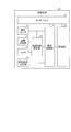
- FIG. 1 is a block diagram illustrating a functional configuration of the information terminal according to the first embodiment.
- An information terminal 10 shown in FIG. 1 is a terminal device that executes information processing.
- palm vein authentication is applied to the screen of the information terminal 10, that is, screen unlocking or login authentication.
- the information terminal 10 displays an image captured by the vein sensor 13 on the screen as a palm alignment aim when the palm sensor 13 provided on the back of the screen images the palm.
- the information terminal 10 changes the position and size of the image displayed on the screen according to the position of the facial organ shown in the image captured by the camera 12 provided on the screen side, for example, the position of the eyes.
- the image processing to be executed is executed.
- the palm is included in one aspect of the first subject.
- the face is included in the second subject.
- the information terminal 10 can be implemented by installing an image processing program provided as package software or online software on a desired computer.
- an image processing program provided as package software or online software
- mobile communication terminals such as smartphones, mobile phones, and PHS (Personal Handyphone System)
- PHS Personal Handyphone System
- a tablet terminal or a slate terminal can be caused to function as the information terminal 10.
- a tablet terminal and a slate terminal are illustrated as examples of implementation of the information terminal 10, but the image processing program may be installed in a fixed terminal such as a personal computer.
- the information terminal 10 includes a touch panel 11, a camera 12, a vein sensor 13, a distance sensor 14, an appropriate arrangement storage unit 15, a viewpoint detection unit 16, a display control unit 17, and authentication. Part 18.
- the information terminal 10 may include various functional units included in known tablet terminals and slate terminals in addition to the functional units illustrated in FIG.
- the information terminal 10 when the information terminal 10 is implemented as a mobile communication terminal, it further includes functional units such as an antenna, a wireless communication unit that performs communication via a mobile communication network, and a GPS (Global Positioning System) receiver. It does not matter.
- the touch panel 11 is a displayable and inputable device.
- the touch panel 11 displays an image output by an OS (Operating System) or an application program, including an image processing program executed on the information terminal 10.
- the touch panel 11 accepts touch operations such as tap, flick, sweep, pinch-in and pinch-out performed on the screen of the screen.
- the camera 12 is an imaging device equipped with an image sensor such as a CCD (Charge Coupled Device) or a CMOS (Complementary Metal Oxide Semiconductor).
- the camera 12 can be equipped with three or more light receiving elements such as R (red), G (green), and B (blue).
- R red
- G green
- B blue
- an in-camera provided on the same surface side as the screen of the tablet terminal or the slate terminal can be used.
- the information terminal 10 does not necessarily have the camera 12 when an image can be acquired via a network or a storage device.
- the camera 12 starts imaging when a touch operation corresponding to a command such as unlocking of the screen or login authentication is performed on the touch panel 11.
- the imaging range of the camera 12 provided on the screen side of the information terminal 10 includes the face of the user of the information terminal 10 viewing the screen display, the neck, clothes, and the like.
- the image captured by the camera 12 also includes the face of the user of the information terminal 10, the neck, clothes, and the like.
- an image captured by the camera 12 may be referred to as a “face image”.
- the vein sensor 13 is a sensor that images a vein blood vessel pattern existing inside the palm.
- the vein sensor 13 includes illumination that emits near-infrared light and an imaging device that includes an image sensor that can capture near-infrared light.
- an out camera provided on the back of the screen of a tablet terminal or a slate terminal can be used as the imaging device.
- the vein sensor 13 is provided in the vicinity of the end of the information terminal 10.
- the information terminal 10 is a rectangular housing
- the information terminal 10 is provided on the surface opposite to the surface on which the screen is installed, that is, on the back surface and in the vicinity of one of the four corners of the housing. .
- the palm is arranged at an appropriate size in the center of the imaging range of the vein sensor 13, the user of the information terminal 10 holding the palm over the vein sensor 13 on the back of the screen while viewing the screen displays the screen. Some of your fingertips may appear to protrude beyond.
- the vein sensor 13 starts imaging when a touch operation corresponding to a command such as unlocking of the screen or login authentication is performed on the touch panel 11. That is, the vein sensor 13 emits near infrared light from illumination. As a result, the vein sensor 13 forms an image of the reflected light of the near-infrared light that has been reflected back from the surface of the palm or the inside of the imaging device that is activated in conjunction with the irradiation of the infrared light from the illumination. As a result, the reflected light imaged on the imaging device is photoelectrically converted to output an image showing the subject within the imaging range of the imaging device.
- the hemoglobin in the vein absorbs near infrared rays, whereby an image in which the vein blood vessel pattern is emphasized can be obtained.
- an image taken by the vein sensor 13 may be referred to as a “palm image”.
- the authentication part including the vein is the palm, but the authentication part may be the back of the hand.
- the camera 12 and the vein sensor 13 activate both of the two imaging devices when the screen is unlocked and login authentication is performed, and an image is captured by each of the two imaging devices. Is imaged.
- an image is captured in synchronization between the camera 12 and the vein sensor 13.
- a palm image frame imaged by the vein sensor 13 and a face image frame imaged by the camera 12 are associated with each other using a frame number or the like. With this association, each of the images having the same frame number can be used for subsequent processing as an image captured at the same time.
- These face images and palm images are imaged using a general information terminal in which one camera is activated by switching the shooting mode and one camera is exclusively used while the other camera is stopped. Draw a line.
- tap operations such as unlocking and login authentication are exemplified as triggers for starting the palm image shooting, but the triggers are not limited to this example.
- it may be started by an operation on a physical key such as a button (not shown).
- a specific gesture such as a wink or a peace sign is detected from an image captured by any of the imaging devices, palm alignment is performed. May start.
- the distance sensor 14 is a sensor that measures the distance between two points.
- the distance sensor 14 emits waves such as infrared rays, radio waves, and ultrasonic waves in a direction instructed from a viewpoint detection unit 16 described later, that is, a direction corresponding to a position where the viewpoint is detected on the face image. Send it out.
- the distance sensor 14 receives the wave reflected from the subject, and measures the distance between the distance sensor 14 and the viewpoint by calculating the time difference or phase difference between the sent wave and the received wave.
- the proper placement storage unit 15 is a storage unit that stores the proper placement of the living body with respect to the vein sensor 13.
- the “appropriate arrangement” mentioned here refers to an arrangement in which a part of the hand appears exposed through the screen when the user holds the palm over the vein sensor in a standard posture that the user takes when using the information terminal 10. For example, when the user of the information terminal 10 holds the information terminal 10 with one hand and holds the palm of the hand over the vein sensor 13 in a posture where the finger of the other hand is extended while viewing the screen display, the thumb and index finger An arrangement in which the fingertips of the middle finger and ring finger are exposed through the screen can be mentioned.
- the appropriate distance between the vein sensor 13 and the palm is determined by the performance of the vein sensor 13 such as the resolution of the image sensor and the number and type of lenses. Note that here, not only when the palm vein authentication is performed, but also when the palm image of the owner of the information terminal 10 is registered in advance, the image is captured in an environment similar to the proper arrangement. A palm image is registered. Hereinafter, a palm image registered in advance may be referred to as a “registered palm image” in order to collate with a palm image captured by the vein sensor 13.
- the proper arrangement storage unit 15 can specify specific information that can specify a rectangle in which the palm surface held up toward the vein sensor 13 is modeled, for example, three-dimensional coordinates of a vertex forming the rectangle or a center of gravity of the rectangle.
- the three-dimensional coordinates and the height and width of the rectangle are stored.
- relative coordinates with respect to the information terminal 10 are adopted as the coordinates here.
- the case where the palm arrangement with respect to the vein sensor 13 is modeled as a rectangle has been illustrated, but an arbitrary shape such as an ellipse, a circle, or a polygon can be used for the modeling.
- the viewpoint detection unit 16 is a processing unit that detects the position of the viewpoint of the user of the information terminal 10.
- the viewpoint detection unit 16 performs image processing such as skin color detection and template matching on the face image captured by the camera 12.
- the viewpoint detection unit 16 extracts a face portion included in the face image by executing skin color detection from the face image.
- the viewpoint detection unit 16 performs template matching on the face area extracted by the skin color detection, so that the shape and size of the facial organs such as eyes, nose, mouth, and ears are obtained from the facial image. Extract geometric features such as As a result, the positions of the right eye, the left eye, or both eyes on the face image are specified.
- the viewpoint detection unit 16 After specifying the position of the eye on the face image in this way, the viewpoint detection unit 16 causes the distance sensor 14 to send out a wave in a direction corresponding to the position of the eye on the face image, thereby the distance sensor 14 and the information terminal.
- the distance between the eyes of 10 users is measured by the distance sensor 14.
- the direction in which the distance sensor 14 sends out the wave may be a direction corresponding to the center of the right eye on the face image, a direction corresponding to the center of the left eye, or an intermediate point between both eyes. It does not matter if the direction corresponds to.
- the viewpoint detection unit 16 obtains information from the distance to the user's eyes of the information terminal 10 measured by the distance sensor 14, the position of the eyes on the face image detected earlier, and the coordinates of the distance sensor 14. The coordinates on the three-dimensional space where the user's eyes of the terminal 10 are located, that is, the position of the viewpoint is calculated.
- the display control unit 17 is a processing unit that performs display control on the touch panel 11. As an aspect, the display control unit 17 obtains a palm image captured by the vein sensor 13 from the position of the viewpoint detected by the viewpoint detection unit 16 and the appropriate arrangement of the palm stored in the appropriate arrangement storage unit 15. The size and position to be displayed on the touch panel 11 are determined.
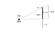
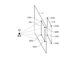
- FIGS. 2 and 3 are diagrams showing an example of a method for determining a display area of a palm image.
- 2 shows a side view when the screen of the information terminal 10 is viewed from the side
- FIG. 3 shows a perspective view when the screen of the information terminal 10 is viewed from an oblique direction.
- the camera 12 and the vein sensor 13 are not shown.
- the position and size of the display area 220 projected on the screen of the touch panel 11. are determined as the display position and the display size.
- the position and size of the display area 220 displayed on the touch panel 11 are defined by the four intersections 220A to 220D.
- intersection 220A indicates a point where a line segment connecting the viewpoint 200 and the vertex 210A intersects the screen of the touch panel 11
- an intersection 220B indicates a point where the line segment connecting the viewpoint 200 and the vertex 210B intersects the screen of the touch panel 11.
- the intersection 220C indicates a point where a line segment connecting the viewpoint 200 and the vertex 210C intersects the screen of the touch panel 11
- the intersection 220D indicates a point where a line segment connecting the viewpoint 200 and the vertex 210D intersects the screen of the touch panel 11.
- the display control unit 17 sets the straight line to the screen of the touch panel 11 for each straight line connecting the viewpoint detected by the viewpoint detection unit 16 and the apex included in the proper arrangement stored in the proper arrangement storage unit 15.
- the display area 220 of the palm image is determined by calculating the coordinates of the intersecting point.
- the position and size of the display area 220 are determined by the arrangement of the four intersections 220A to 220D. For example, the closer the viewpoint 200 is to the screen, the smaller the size of the display area 220. The further the viewpoint is away from the screen, the closer the display area 220 is to the size of the proper arrangement 210.
- the display control unit 17 causes the touch panel 11 to display a palm image captured by the vein sensor 13 according to the previously determined display position and display size. For example, in the example of FIGS. 2 and 3, the palm image captured by the vein sensor 13 is displayed in the display area 220 including the intersections 220A to 220D.
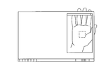
- FIG. 4 to 6 are diagrams showing examples of palm images displayed on the touch panel 11.
- FIG. 4 shows a mode in which the palm is held at a position overlapping the proper arrangement 210.
- the finger end of the palm image displayed on the touch panel 11 and the actual fingertip exposed through the screen are connected without a sense of incongruity. Looks.
- the user of the information terminal 10 can confirm the situation in which the palm is presented at an appropriate position. As a result, the user can keep the palm at the current presentation position until the palm vein authentication is completed. .
- FIG. 5 shows a mode in which the palm is held at a position closer to the screen than the proper arrangement 210.
- the finger of the palm image displayed on the touch panel 11 is started compared to the actual scale of the fingertip exposed through the screen.
- the palm scale is displayed larger.
- the distance from the vein sensor 13 to the fingertip is shorter than the distance from the viewpoint of the user of the information terminal 10 to the fingertip, and thus the vein sensor 13 is often provided with a wide-angle lens.
- a palm image can be displayed.
- the user of the information terminal 10 can check the situation where the palm is presenting closer than the appropriate position, and as a result, the user presents the information terminal 10 away from the casing of the information terminal 10 than the current presentation position. It can be judged that it is good to do.
- FIG. 6 shows a state in which the palm is held at a position farther from the screen than the proper arrangement 210.
- the finger of the palm image displayed on the touch panel 11 is compared with the actual scale of the fingertip exposed through the screen.
- the palm scale is displayed small. For this reason, even if the palm is presented farther away from the screen than the proper arrangement 210, it is difficult for the user who is looking at the fingertip through the screen to see the palm of the palm on a scale smaller than the actual scale of the fingertip that is visible over the screen. A palm image showing your fingertips can be displayed.
- the user of the information terminal 10 can check the situation where the palm is presenting away from the proper position, and as a result, the information terminal 10 is presented closer to the casing of the information terminal 10 than the present presentation position. It can be judged that it is good to do.
- FIGS. 4 to 6 unlike displaying a palm image directly in front of the user's viewpoint of the information terminal 10, from the front of the user of the information terminal 10 in the direction toward the proper arrangement. Shift to display the palm image. For this reason, the user of the information terminal 10 can present the palm while intuitively grasping the visual field of the vein sensor 13 that is installed on the back of the screen and is difficult to view. Also, as shown in FIGS. 4 to 6, the center position of the range in which the blood vessel pattern inside the palm is extracted is displayed superimposed on the palm image, so that the palm can be aligned with the position as a sight. it can.
- the authentication unit 18 is a processing unit that performs palm vein authentication.
- the authentication unit 18 extracts a feature amount related to a vein blood vessel pattern from a palm image captured by the vein sensor 13. For example, the authentication unit 18 extracts a blood vessel portion from the palm image and thins it, and extracts feature quantities such as the coordinates of branch points in the blood vessel, the length between the branch points, and the branch angle of the branch points as vein data. Then, the authentication unit 18 calculates a collation score between the vein data extracted from the palm image and the vein data of the owner of the information terminal 10 registered in advance.
- not only one-to-one authentication but also one-to-N authentication can be performed by registering a plurality of vein data of persons who are permitted to use the information terminal 10.
- the authentication part 18 determines with palm vein authentication having been successful, when the largest collation score among the collation scores calculated previously is more than a predetermined threshold value. Further, the authentication unit 18 determines that palm vein authentication has failed when the maximum matching score is less than or equal to a predetermined value.
- the authentication result obtained by performing palm vein authentication in this manner by the authentication unit 18 is output to an OS or application program that performs lock release or login authentication.
- the authentication unit 18 can employ any verification method such as a minutiae method, a pattern matching method, or a frequency analysis method.
- the authentication unit 18 does not always immediately perform palm vein authentication. That is, every time a palm image is captured by the vein sensor 13, the authentication unit 18 determines whether or not the palm shown in the palm image is arranged at an appropriate position. For example, the authentication unit 18 performs palm vein authentication when the difference between the thickness of the finger shown in the palm image captured by the vein sensor 13 and the thickness of the finger of the vein data registered in advance is within a predetermined threshold. Can be executed. Further, the authentication unit 18 can execute palm vein authentication when receiving an input of a predetermined voice message, for example, “OK” from the user of the information terminal 10. Even if the palm vein authentication fails, the authentication unit 18 causes the display control unit 17 to display a palm image on the touch panel 11 until the number of palm vein authentication retries reaches a predetermined number. Can be retried.
- the viewpoint detection unit 16, the display control unit 17, and the authentication unit 18 can be realized by causing a CPU (Central Processing Unit), an MPU (Micro Processing Unit), or the like to execute an image processing program.
- a CPU Central Processing Unit
- MPU Micro Processing Unit
- Each of the above functional units can be realized by hard wired logic such as ASIC (Application Specific Integrated Circuit) or FPGA (Field Programmable Gate Array).
- a semiconductor memory element or a storage device can be adopted as the proper arrangement storage unit 15.
- VRAM Video Random Access Memory
- RAM Random Access Memory
- ROM Read Only Memory
- flash memory etc.
- examples of the storage device include storage devices such as a hard disk and an optical disk.
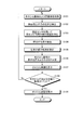
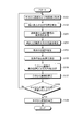
- FIG. 7 is a flowchart illustrating the authentication processing procedure according to the first embodiment. As an example, this authentication process is started when a touch operation corresponding to a command such as unlocking the screen or login authentication is performed on the touch panel 11.
- step S101 when a facial image is captured by the camera 12 and a palm image is captured by the vein sensor 13 (step S101), the viewpoint detection unit 16 performs the processing on the facial image captured in step S101. The position of the user's eyes is detected (step S102).
- the viewpoint detection unit 16 causes the distance sensor 14 to send out a wave in a direction corresponding to the position of the eye on the face image detected in step S ⁇ b> 102, so that the eyes of the user of the distance sensor 14 and the information terminal 10 are used.
- the distance sensor 14 is caused to measure the distance between them (step S103).
- the viewpoint detection unit 16 obtains information from the distance to the user's eyes of the information terminal 10 measured in step S103, the eye position on the face image detected in step S102, and the coordinates of the distance sensor 14. The coordinates on the three-dimensional space where the eyes of the user of the terminal 10 are located, that is, the position of the viewpoint is calculated (step S104).
- the display control unit 17 reads out the proper arrangement stored in the proper arrangement storage unit 15 (step S105). In addition, the display control unit 17 calculates the coordinates of the intersection of the straight line and the screen for each straight line connecting the viewpoint detected in step S104 and the vertex included in the appropriate arrangement read in step S105. By doing so, the display area of the palm image, that is, the display position and the display size are determined (step S106).
- the display control unit 17 causes the touch panel 11 to display the palm image captured in step S101 according to the display position and display size determined in step S106 (step S107).
- step S101 to step S107 is repeatedly executed until it is determined by the authentication unit 18 that the palm included in the palm image is placed at an appropriate position (No in step S108).
- the authentication unit 18 executes the following process. That is, the authentication unit 18 performs palm vein authentication by comparing vein data extracted from the palm image captured in step S101 with vein data registered in advance (step S109), and the authentication result is sent to the information terminal 10. The data is output to the OS or application program operating above, and the process is terminated.
- the information terminal 10 when the information terminal 10 according to the present embodiment captures the palm with the vein sensor 13 installed on the back surface of the screen, the information terminal 10 reflects the eyes displayed on the camera 12 installed on the same surface as the screen. The position and size of the palm image displayed on the screen are changed depending on the position. For example, when a part of the hand, for example, a fingertip, is exposed through the screen, the palm is positioned at the center of the palm image, and the palm or finger scale reflected in the palm image matches the actual fingertip scale. Can be aligned. For this reason, in the information terminal 10 which concerns on a present Example, even when the vein sensor 13 is installed in the back surface of a screen, the precision of alignment can be improved. Therefore, according to the information terminal 10 according to the present embodiment, the authentication accuracy can be improved.
- the distance sensor 14 is used to detect the position of the viewpoint of the user of the information terminal 10.
- the distance sensor 14 may not be provided. is there. Therefore, in this embodiment, the information terminal 20 that estimates the position of the user's viewpoint without using the distance sensor 14 will be described below.
- FIG. 8 is a block diagram illustrating a functional configuration of the information terminal 20 according to the second embodiment.
- the information terminal 20 shown in FIG. 8 is different from the information terminal 10 shown in FIG. 1 in that it includes a distance storage unit 21 and a viewpoint position estimation unit 22.
- processing units having different functions from those of the information terminal 10 illustrated in FIG. 1 are denoted by different reference numerals, and those having the same functions are denoted by the same reference numerals and description thereof. Will be omitted.
- the distance storage unit 21 is a storage unit that stores the distance to the information terminal 20.
- the distance storage unit 21 includes the number of pixels forming the width of the face on the face image when a standard person is captured by the camera 12, the face of the standard person, and the information terminal 20.
- the data associated with the distance measured in step 1 is stored.
- standard person refers to a person whose face width is statistically an average value or median value.
- the viewpoint position estimation unit 22 has the same processing until the position of the right eye, the left eye, or both eyes on the face image is specified, but the subsequent processing is different. . More specifically, the viewpoint position estimation unit 22 reads from the distance storage unit 21 the width of the face and the measurement distance to the information terminal 20 when a standard person is imaged. Then, the viewpoint position estimation unit 22 counts the number of pixels forming the width of the face of the user of the information terminal 20 from the face image captured by the camera 12 by executing image processing such as skin color detection and template matching. .
- the viewpoint position estimation unit 22 determines the width of the face of the user of the information terminal 20 in which the number of pixels is counted from the face image and the face on the face image when a standard person is captured by the camera 12. A ratio between the number of horizontal pixels, for example, a division value obtained by dividing the former width by the latter width is calculated. In addition, the viewpoint position estimation unit 22 adds the reciprocal of the ratio calculated earlier to the measurement distance between the standard human face read from the distance storage unit 21 and the information terminal 20, that is, the reciprocal of the division value. Is used to estimate the distance between the face of the user of the information terminal 20 and the information terminal 20.
- the width of the face of the user of the information terminal 20 is regarded as the width of a standard person, and the standard width of the face is obtained in advance in accordance with the expansion / contraction of the width of the face obtained by taking the face image.
- the measurement distance when the image is taken can be corrected. For example, when the user of the information terminal 20 brings the face closer to the screen than when a standard person's face is photographed in advance, the width of the user's face is detected to be large. In this case, since the above ratio is calculated to be larger than 1, the measurement distance in the case where a standard person is photographed in advance can be corrected to be small by multiplying the reciprocal of the ratio.
- the measurement distance in the case of photographing with a standard person in advance can be greatly corrected by multiplying the reciprocal of the ratio.
- the difference between the two may be calculated.
- the measurement distance is corrected to be large, while the face of the user of the information terminal 20 is corrected.
- the measurement distance may be corrected to be small.
- the viewpoint position estimation unit 22 determines the distance to the user's face of the information terminal 20 estimated previously, the eye position on the face image detected earlier, and the coordinates of the information terminal 20, for example, the center of gravity of the screen And the coordinates on the three-dimensional space where the user's eyes of the information terminal 20 are located, that is, the position of the viewpoint is estimated.
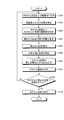
- FIG. 9 is a flowchart illustrating the authentication processing procedure according to the second embodiment. Similarly to the flowchart shown in FIG. 7, this authentication process also starts when a touch operation corresponding to a command such as unlocking the screen or login authentication is performed on the touch panel 11.
- step S101 when a facial image is captured by the camera 12 and a palm image is captured by the vein sensor 13 (step S101), the viewpoint position estimation unit 22 performs the processing on the facial image captured in step S101. The position of the user's eyes is detected (step S102).
- the viewpoint position estimation unit 22 counts the number of pixels forming the width of the face of the user of the information terminal 20 from the face image captured in step S101 by executing image processing such as skin color detection and template matching. (Step S201).
- the viewpoint position estimation unit 22 stores the distance using the ratio between the number of pixels of the width of the face counted in step S201 and the number of pixels of the width of the face on the face image stored in the distance storage unit 21.
- the distance between the user's face of the information terminal 20 and the information terminal 20 is estimated by correcting the measurement distance between the standard human face stored in the unit 21 and the information terminal 20 (step S202).
- the viewpoint position estimation unit 22 obtains information from the distance to the user's eyes of the information terminal 20 estimated in step S202, the eye position on the face image detected in step S102, and the coordinates of the information terminal 20.
- the coordinates on the three-dimensional space where the user's eyes of the terminal 20 are located, that is, the position of the viewpoint is estimated (step S203).
- the display control unit 17 reads out the proper arrangement stored in the proper arrangement storage unit 15 (step S105). After that, the display control unit 17 calculates the coordinates of the intersection of the straight line and the screen for each straight line connecting the viewpoint estimated in step S203 and the vertex included in the proper arrangement read in step S105. By doing so, the display area of the palm image, that is, the display position and the display size are determined (step S106).
- the display control unit 17 causes the touch panel 11 to display the palm image captured in step S101 according to the display position and display size determined in step S106 (step S107).
- step S101 to step S107 is repeatedly executed until it is determined by the authentication unit 18 that the palm included in the palm image is placed at an appropriate position (No in step S108).
- the authentication unit 18 executes the following process. That is, the authentication unit 18 performs palm vein authentication by comparing vein data extracted from the palm image captured in step S101 with vein data registered in advance (step S109), and the authentication result is transmitted to the information terminal 20. The data is output to the OS or application program operating above, and the process is terminated.
- the width of the face of the user of the information terminal 20 is regarded as a standard width of the person, and the width of the face obtained by the current face image shooting is expanded or reduced.
- the position of the viewpoint can be estimated without hardware such as the distance sensor 14.
- the viewpoint position of the user of the information terminal 20 is estimated from the width of the face reflected in the face image captured by the camera 12 . It is not necessary to use the width of. Therefore, in the present embodiment, the information terminal 30 that estimates the position of the user's viewpoint using the palm image captured by the vein sensor 13 will be described below.
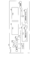
- FIG. 10 is a block diagram illustrating a functional configuration of the information terminal 30 according to the third embodiment.
- the information terminal 30 illustrated in FIG. 10 is different from the information terminal 20 illustrated in FIG. 8 in that the information terminal 30 includes a distance storage unit 31 and a viewpoint position estimation unit 32.
- different reference numerals are given to processing units having different functions from those of the information terminal 20 shown in FIG. 8, and those having the same functions are denoted by the same reference numerals and description thereof. Will be omitted.
- the distance storage unit 31 is a storage unit that stores the distance to the information terminal 30.
- the distance storage unit 31 includes the number of pixels forming the width of the palm on the palm image when the standard person is imaged by the vein sensor 13, the face of the standard person, and the information terminal 30. The data in which the distance measured between them is associated is stored.
- standard person refers to a person whose palm width is statistically an average value or a median value.
- the horizontal width of the palm and the distance to the information terminal 30 are stored in association with each other is illustrated here, the vertical width of the palm or the length of the finger and the measurement distance are stored in association with each other. It doesn't matter as you do.
- the viewpoint position estimation unit 32 is common in processing until the position of the right eye, left eye, or both eyes on the face image is specified, but the subsequent processing is different. To do. More specifically, the viewpoint position estimation unit 32 reads the lateral width of the palm and the measurement distance to the information terminal 30 when a standard person is imaged from the distance storage unit 31. Then, the viewpoint position estimation unit 32 counts the number of pixels forming the width of the palm of the user of the information terminal 30 from the palm image captured by the vein sensor 13 by executing image processing such as skin color detection and template matching. To do.
- the viewpoint position estimation unit 32 measures the width of the palm of the user of the information terminal 30 in which the number of pixels is counted from the palm image, and the palm on the palm image when a standard person is imaged by the vein sensor 13. A ratio, for example, a division value obtained by dividing the former width by the latter width is calculated. Then, the viewpoint position estimation unit 32 multiplies the measurement distance between the standard human face read from the distance storage unit 31 and the information terminal 30 by the previously calculated ratio, that is, the division value. Thus, the distance between the user's face of the information terminal 30 and the information terminal 30 is estimated.
- the width of the palm of the user of the information terminal 30 and the distance between the eyes of the user of the information terminal 30 and the information terminal 30 are both derived from the physique, it is considered to have a proportional relationship
- the measurement distance when the image is taken in advance by a standard person can be corrected according to the expansion / contraction of the width of the palm obtained by taking the palm image this time. For example, when the palm of the user of the information terminal 30 is larger than the palm of a standard person photographed in advance, the lateral width of the palm is detected. In this case, since the above ratio is calculated to be greater than 1, the measurement distance when the image is taken in advance by a standard person can be greatly corrected by multiplying the ratio.
- the lateral width of the palm is detected to be small.
- the measurement distance when the image is taken in advance with a standard person can be corrected by multiplying the ratio.
- the difference between the two may be calculated.
- the measurement distance is corrected to be small, while the palm of the palm of the user of the information terminal 30 is corrected.
- the measurement distance may be corrected to be large.
- the viewpoint position estimation unit 32 determines the previously estimated distance to the user's face of the information terminal 30, the position of the eye on the previously detected face image, and the coordinates of the information terminal 30, for example, the center of gravity of the screen
- the coordinates on the three-dimensional space where the user's eyes of the information terminal 30 are located, that is, the position of the viewpoint is estimated from the coordinates of the information.
- FIG. 11 is a flowchart illustrating a procedure of authentication processing according to the third embodiment. Similarly to the flowchart shown in FIG. 7, this authentication process also starts when a touch operation corresponding to a command such as unlocking the screen or login authentication is performed on the touch panel 11.
- step S101 when a facial image is captured by the camera 12 and a palm image is captured by the vein sensor 13 (step S101), the viewpoint position estimation unit 32 performs the processing on the facial image captured in step S101. The position of the user's eyes is detected (step S102).
- the viewpoint position estimation unit 32 counts the number of pixels forming the width of the palm of the user of the information terminal 30 from the palm image captured in step S101 by performing image processing such as skin color detection and template matching. (Step S301).
- the viewpoint position estimation unit 32 uses the ratio between the number of pixels of the width of the palm counted in step S301 and the number of pixels of the width of the palm on the palm image stored in the distance storage unit 31 to store the distance.
- the distance between the face of the user of the information terminal 30 and the information terminal 30 is estimated by correcting the measurement distance between the standard human face stored in the unit 31 and the information terminal 30 (step S302).
- the viewpoint position estimation unit 32 obtains information from the distance to the user's eyes of the information terminal 30 estimated in step S302, the eye position on the face image detected in step S102, and the coordinates of the information terminal 30.
- the coordinates on the three-dimensional space where the user's eyes of the terminal 30 are located, that is, the position of the viewpoint is estimated (step S303).
- the display control unit 17 reads out the proper arrangement stored in the proper arrangement storage unit 15 (step S105). After that, the display control unit 17 calculates the coordinates of the intersection of the straight line and the screen for each straight line connecting the viewpoint estimated in step S303 and the vertex included in the appropriate arrangement read in step S105. By doing so, the display area of the palm image, that is, the display position and the display size are determined (step S106).
- the display control unit 17 causes the touch panel 11 to display the palm image captured in step S101 according to the display position and display size determined in step S106 (step S107).
- step S101 to step S107 is repeatedly executed until it is determined by the authentication unit 18 that the palm included in the palm image is placed at an appropriate position (No in step S108).
- the authentication unit 18 executes the following process. That is, the authentication unit 18 performs palm vein authentication by comparing vein data extracted from the palm image captured in step S101 with vein data registered in advance (step S109), and the authentication result is transmitted to the information terminal 20. The data is output to the OS or application program operating above, and the process is terminated.
- the width of the palm of the user of the information terminal 30 and the distance between the eyes of the information terminal 30 and the user of the information terminal 30 are regarded as having a proportional relationship
- the measurement distance is corrected when the image is taken by a standard person in advance according to the expansion / contraction of the width of the palm obtained by taking the palm image.
- the position of the viewpoint can be estimated without the hardware such as the distance sensor 14.
- the information terminal 10, 20 or 30 has the camera 12 as an example, but the camera 12 is not necessarily required.
- the viewpoint of the user of the information terminal 10, 20 or 30 is present in a specific direction with respect to the terminal, and in the normal direction of the center of the screen. Can be stored in the internal memory or the like. Thereby, the position of the viewpoint can be detected or estimated even if the camera 12 is not provided on the same surface side as the screen.
- each component of each illustrated apparatus does not necessarily need to be physically configured as illustrated.
- the specific form of distribution / integration of each device is not limited to that shown in the figure, and all or a part thereof may be functionally or physically distributed or arbitrarily distributed in arbitrary units according to various loads or usage conditions. Can be integrated and configured.
- the viewpoint detection unit 16 or the display control unit 17 may be connected as an external device of the information terminal 10 via a network.
- the viewpoint detection unit 16 or the display control unit 17 may be provided in another device, and the functions of the information terminal 10 may be realized by being connected to a network and cooperating.
- FIG. 12 is a diagram for explaining an example of a computer that executes an image processing program according to the first to third embodiments.
- the computer 100 includes an operation unit 110a, a speaker 110b, a camera 110c, a display 120, and a communication unit 130. Further, the computer 100 includes a CPU 150, a ROM 160, an HDD 170, and a RAM 180. These units 110 to 180 are connected via a bus 140.
- the HDD 170 stores in advance an image processing program 170a that exhibits the same functions as the viewpoint detection unit 16 and the display control unit 17 described in the first embodiment. Further, the HDD 170 may store in advance an image processing program 170a that exhibits the same functions as the viewpoint position estimation unit 22 and the display control unit 17 described in the second embodiment. The HDD 170 may store in advance an image processing program 170a that exhibits the same functions as the viewpoint position estimation unit 32 and the display control unit 17 described in the third embodiment.
- the image processing program 170a may be integrated or separated as appropriate, as with each component of each functional unit shown in FIG. 1, FIG. 8, or FIG. In other words, all data stored in the HDD 170 need not always be stored in the HDD 170, and only data necessary for processing may be stored in the HDD 170.
- the CPU 150 reads the image processing program 170a from the HDD 170 and develops it in the RAM 180.
- the image processing program 170a functions as an image processing process 180a.
- the image processing process 180a expands various data read from the HDD 170 in an area allocated to itself on the RAM 180 as appropriate, and executes various processes based on the expanded data.
- the image processing process 180a includes processing executed by each functional unit shown in FIG. 1, FIG. 8, or FIG. 10, for example, processing shown in FIG. 7, FIG. 9, and FIG.
- each processing unit virtually realized on the CPU 150 does not always require that all processing units operate on the CPU 150, and only a processing unit necessary for the processing needs to be virtually realized.
- each program is stored in a “portable physical medium” such as a flexible disk inserted into the computer 100, so-called FD, CD-ROM, DVD disk, magneto-optical disk, or IC card. Then, the computer 100 may acquire and execute each program from these portable physical media.
- each program is stored in another computer or server device connected to the computer 100 via a public line, the Internet, a LAN, a WAN, etc., and the computer 100 acquires and executes each program from these. It may be.
Landscapes
- Engineering & Computer Science (AREA)
- Theoretical Computer Science (AREA)
- General Physics & Mathematics (AREA)
- Physics & Mathematics (AREA)
- General Engineering & Computer Science (AREA)
- Human Computer Interaction (AREA)
- Multimedia (AREA)
- Computer Security & Cryptography (AREA)
- Computer Vision & Pattern Recognition (AREA)
- Software Systems (AREA)
- Computer Hardware Design (AREA)
- Oral & Maxillofacial Surgery (AREA)
- General Health & Medical Sciences (AREA)
- Health & Medical Sciences (AREA)
- Image Input (AREA)
- Measurement Of The Respiration, Hearing Ability, Form, And Blood Characteristics Of Living Organisms (AREA)
- Collating Specific Patterns (AREA)
- User Interface Of Digital Computer (AREA)
Abstract
Description
まず、本実施例に係る情報端末の機能的構成について説明する。図1は、実施例1に係る情報端末の機能的構成を示すブロック図である。図1に示す情報端末10は、情報処理を実行する端末装置である。図1の例では、情報端末10の画面、すなわちスクリーンのロック解除やログインの認証に手のひら静脈認証が適用される場合を想定して以下の説明を行う。
図7は、実施例1に係る認証処理の手順を示すフローチャートである。この認証処理は、一例として、タッチパネル11上でスクリーンのロック解除またはログイン認証などのコマンドに対応するタッチ操作がなされた場合に、処理が起動する。
上述してきたように、本実施例に係る情報端末10は、画面の背面に設置された静脈センサ13で手のひらを撮影する場合に、画面と同じ側の面に設置されたカメラ12に映る目の位置によって画面に表示させる手のひら画像の位置及び大きさを変更する。例えば、スクリーン越しに手の一部、例えば指先が露出する場合には、手のひら画像の中央に手のひらが位置し、さらに、手のひら画像に映る手のひらや指のスケールが露出する実物の指先のスケールと合うように位置合わせできる。このため、本実施例に係る情報端末10では、画面の背面に静脈センサ13が設置される場合でも、位置合わせの精度を高めることができる。したがって、本実施例に係る情報端末10によれば、認証精度を向上させることができる。
上述してきたように、本実施例に係る情報端末20によれば、画面の背面に静脈センサ13が設置される場合でも、位置合わせの精度を高めることができるので、上記の実施例1と同様に、認証精度を向上させることができる。
上述してきたように、本実施例に係る情報端末30によれば、画面の背面に静脈センサ13が設置される場合でも、位置合わせの精度を高めることができるので、上記の実施例1と同様に、認証精度を向上させることができる。
上記の実施例1~実施例3では、情報端末10、20または30がカメラ12を有する場合を例示したが、カメラ12は必ずしも有していなくともよい。例えば、顔画像上の目の位置を検出する代わりに、情報端末10、20または30の使用者の視点が端末を基準に特定の方向、スクリーンの中心の法線方向に存在するとみなし、当該視点が情報端末10、20または30に対して位置する方向を内部メモリ等に保持しておくこともできる。これによって、画面と同一の面側にカメラ12が設けられておらずとも、視点の位置を検出または推定できる。
上記の実施例1~実施例3では、手のひら静脈認証を実行する場合に上記の画像処理を実行する場合を例示したが、これ以外の認証が実行される場合にも適用することができる。すなわち、ユーザの目の位置と認証部位の間にカメラ、画面および認証用のセンサを有する装置が存在し、認証用のセンサと認証部位が離れている場合に上記の画像処理を同様に適用できる。例えば、情報端末10、20または30の背面に設置された撮像デバイスで掌紋、手の甲または掌形(手形)を撮像して掌紋認証、手の甲認証または掌形認証を実行する場合にも、上記の画像処理、すなわち図7、図9や図11で示した処理を実行できる。
また、図示した各装置の各構成要素は、必ずしも物理的に図示の如く構成されていることを要しない。すなわち、各装置の分散・統合の具体的形態は図示のものに限られず、その全部または一部を、各種の負荷や使用状況などに応じて、任意の単位で機能的または物理的に分散・統合して構成することができる。例えば、視点検出部16または表示制御部17を情報端末10の外部装置としてネットワーク経由で接続するようにしてもよい。また、視点検出部16または表示制御部17を別の装置がそれぞれ有し、ネットワーク接続されて協働することで、上記の情報端末10の機能を実現するようにしてもよい。
また、上記の実施例で説明した各種の処理は、予め用意されたプログラムをパーソナルコンピュータやワークステーションなどのコンピュータで実行することによって実現することができる。そこで、以下では、図12を用いて、上記の実施例と同様の機能を有する画像処理プログラムを実行するコンピュータの一例について説明する。
11 タッチパネル
12 カメラ
13 静脈センサ
14 距離センサ
15 適正配置記憶部
16 視点検出部
17 表示制御部
18 認証部
Claims (12)
- 画面と、該画面が配置された面の裏面に設けられた第一のセンサと、第二のセンサとを備えた情報端末に、
前記第一のセンサによって撮像された第一の被写体の画像を前記画面に表示させる際に、該画像の拡縮度合い及び表示位置を、前記情報端末に設けられた第二のセンサによって撮像された第二の被写体の位置に応じて変更する
処理を実行させることを特徴とする画像処理プログラム。 - 前記情報端末に、
距離を測定する距離センサを用いて、前記情報端末および前記第二の被写体の距離を測定し、
前記情報端末および前記第二の被写体の距離から前記第二の被写体の位置を検出する処理をさらに実行させることを特徴とする請求項1に記載の画像処理プログラム。 - 前記第二の被写体は、前記情報端末の使用者の顔を含み、
前記情報端末に、
前記第二のセンサによって撮像された画像から得られる顔の特徴点間の距離を用いて、前記情報端末および前記情報端末の使用者の顔の間の距離を推定し、
前記情報端末および前記情報端末の使用者の顔の間の距離から前記第二の被写体の位置を推定する処理をさらに実行させることを特徴とする請求項1に記載の画像処理プログラム。 - 前記第一の被写体は、前記情報端末の使用者の生体を含み、
前記情報端末に、
前記第一のセンサによって撮像された画像から得られる生体の大きさを用いて、前記情報端末および前記情報端末の使用者の顔の間の距離を推定し、
前記情報端末および前記情報端末の使用者の顔の間の距離から前記第二の被写体の位置を推定する処理をさらに実行させることを特徴とする請求項1に記載の画像処理プログラム。 - 画面と、該画面が配置された面の裏面に設けられた第一のセンサと、第二のセンサとを備えた情報端末が、
前記第一のセンサによって撮像された第一の被写体の画像を前記画面に表示させる際に、該画像の拡縮度合い及び表示位置を、前記情報端末に設けられた第二のセンサによって撮像された第二の被写体の位置に応じて変更する
処理を実行することを特徴とする画像処理方法。 - 前記情報端末が、
距離を測定する距離センサを用いて、前記情報端末および前記第二の被写体の距離を測定し、
前記情報端末および前記第二の被写体の距離から前記第二の被写体の位置を検出する処理をさらに実行することを特徴とする請求項5に記載の画像処理方法。 - 前記第二の被写体は、前記情報端末の使用者の顔を含み、
前記情報端末が、
前記第二のセンサによって撮像された画像から得られる顔の特徴点間の距離を用いて、前記情報端末および前記情報端末の使用者の顔の間の距離を推定し、
前記情報端末および前記情報端末の使用者の顔の間の距離から前記第二の被写体の位置を推定する処理をさらに実行することを特徴とする請求項5に記載の画像処理方法。 - 前記第一の被写体は、前記情報端末の使用者の生体を含み、
前記情報端末が、
前記第一のセンサによって撮像された画像から得られる生体の大きさを用いて、前記情報端末および前記情報端末の使用者の顔の間の距離を推定し、
前記情報端末および前記情報端末の使用者の顔の間の距離から前記第二の被写体の位置を推定する処理をさらに実行することを特徴とする請求項5に記載の画像処理方法。 - 画面と、該画面が配置された面の裏面に設けられた第一のセンサと、第二のセンサとを備えた情報端末であって、
前記第一のセンサによって撮像された第一の被写体の画像を前記画面に表示させる際に、該画像の拡縮度合い及び表示位置を、前記情報端末に設けられた第二のセンサによって撮像された第二の被写体の位置に応じて変更する表示制御部
を有することを特徴とする情報端末。 - 前記情報端末および前記第二の被写体の距離を測定する測定部と、
前記情報端末および前記第二の被写体の距離から前記第二の被写体の位置を検出する検出部とをさらに有することを特徴とする請求項9に記載の情報端末。 - 前記第二の被写体は、前記情報端末の使用者の顔を含み、
前記第二のセンサによって撮像された画像から得られる顔の特徴点間の距離を用いて、前記情報端末および前記情報端末の使用者の顔の間の距離を推定し、前記情報端末および前記情報端末の使用者の顔の間の距離から前記第二の被写体の位置を推定する推定部をさらに有することを特徴とする請求項9に記載の情報端末。 - 前記第一の被写体は、前記情報端末の使用者の生体を含み、
前記第一のセンサによって撮像された画像から得られる生体の大きさを用いて、前記情報端末および前記情報端末の使用者の顔の間の距離を推定し、前記情報端末および前記情報端末の使用者の顔の間の距離から前記第二の被写体の位置を推定する推定部をさらに有することを特徴とする請求項9に記載の情報端末。
Priority Applications (6)
| Application Number | Priority Date | Filing Date | Title |
|---|---|---|---|
| EP13882966.8A EP2991027B1 (en) | 2013-04-26 | 2013-04-26 | Image processing program, image processing method and information terminal |
| PCT/JP2013/062431 WO2014174674A1 (ja) | 2013-04-26 | 2013-04-26 | 画像処理プログラム、画像処理方法及び情報端末 |
| KR1020157030235A KR101711781B1 (ko) | 2013-04-26 | 2013-04-26 | 화상 처리 프로그램을 기록한 기록 매체, 화상 처리 방법 및 정보 단말기 |
| CN201380075945.3A CN105144228B (zh) | 2013-04-26 | 2013-04-26 | 图像处理方法以及信息终端 |
| JP2015513466A JP6052399B2 (ja) | 2013-04-26 | 2013-04-26 | 画像処理プログラム、画像処理方法及び情報端末 |
| US14/885,004 US9697415B2 (en) | 2013-04-26 | 2015-10-16 | Recording medium, image processing method, and information terminal |
Applications Claiming Priority (1)
| Application Number | Priority Date | Filing Date | Title |
|---|---|---|---|
| PCT/JP2013/062431 WO2014174674A1 (ja) | 2013-04-26 | 2013-04-26 | 画像処理プログラム、画像処理方法及び情報端末 |
Related Child Applications (1)
| Application Number | Title | Priority Date | Filing Date |
|---|---|---|---|
| US14/885,004 Continuation US9697415B2 (en) | 2013-04-26 | 2015-10-16 | Recording medium, image processing method, and information terminal |
Publications (1)
| Publication Number | Publication Date |
|---|---|
| WO2014174674A1 true WO2014174674A1 (ja) | 2014-10-30 |
Family
ID=51791278
Family Applications (1)
| Application Number | Title | Priority Date | Filing Date |
|---|---|---|---|
| PCT/JP2013/062431 Ceased WO2014174674A1 (ja) | 2013-04-26 | 2013-04-26 | 画像処理プログラム、画像処理方法及び情報端末 |
Country Status (6)
| Country | Link |
|---|---|
| US (1) | US9697415B2 (ja) |
| EP (1) | EP2991027B1 (ja) |
| JP (1) | JP6052399B2 (ja) |
| KR (1) | KR101711781B1 (ja) |
| CN (1) | CN105144228B (ja) |
| WO (1) | WO2014174674A1 (ja) |
Cited By (3)
| Publication number | Priority date | Publication date | Assignee | Title |
|---|---|---|---|---|
| JP2015187783A (ja) * | 2014-03-26 | 2015-10-29 | 富士通株式会社 | 携帯型情報処理装置、及びプログラム |
| EP3358489A1 (en) | 2017-02-07 | 2018-08-08 | Fujitsu Limited | Biometric authentication apparatus, biometric authentication method, and non-transitory computer-readable storage medium for storing program for biometric authentication |
| US20180349670A1 (en) * | 2016-02-01 | 2018-12-06 | Fujitsu Limited | Biometric information process device, biometric information process method, computer-readable non-transitory medium and distance detection device |
Families Citing this family (13)
| Publication number | Priority date | Publication date | Assignee | Title |
|---|---|---|---|---|
| CN105809049B (zh) * | 2014-12-30 | 2019-11-05 | 中兴通讯股份有限公司 | 加解密的方法、装置及移动终端 |
| CN105045395A (zh) * | 2015-08-28 | 2015-11-11 | 京东方科技集团股份有限公司 | 一种显示装置及画面显示方法 |
| US11328152B2 (en) | 2019-06-17 | 2022-05-10 | Pixart Imaging Inc. | Recognition system employing thermal sensor |
| US11116407B2 (en) | 2016-11-17 | 2021-09-14 | Aranz Healthcare Limited | Anatomical surface assessment methods, devices and systems |
| US10255507B2 (en) * | 2016-12-19 | 2019-04-09 | Canon Kabushiki Kaisha | Detection of an object in a distorted image |
| CN106774937B (zh) * | 2017-01-13 | 2020-01-10 | 宇龙计算机通信科技(深圳)有限公司 | 一种增强现实技术中的图像交互方法及其装置 |
| CN111183456A (zh) * | 2017-10-03 | 2020-05-19 | 富士通株式会社 | 识别程序、识别方法以及识别装置 |
| EP3693924B1 (en) * | 2017-10-03 | 2023-08-02 | Fujitsu Limited | Posture recognition system, image correction program, and image correction method |
| JP2019086365A (ja) * | 2017-11-06 | 2019-06-06 | 株式会社日立製作所 | 位置推定システム |
| CN109960964A (zh) * | 2017-12-14 | 2019-07-02 | 红石生物特征科技有限公司 | 非接触式掌纹获取装置及其方法 |
| US12039726B2 (en) * | 2019-05-20 | 2024-07-16 | Aranz Healthcare Limited | Automated or partially automated anatomical surface assessment methods, devices and systems |
| US11615639B1 (en) * | 2021-01-27 | 2023-03-28 | Jackson Klein | Palm vein identification apparatus and method of use |
| CN113590250B (zh) * | 2021-07-29 | 2024-02-27 | 网易(杭州)网络有限公司 | 图像处理方法、装置、设备及存储介质 |
Citations (11)
| Publication number | Priority date | Publication date | Assignee | Title |
|---|---|---|---|---|
| JP2004258714A (ja) | 2003-02-24 | 2004-09-16 | Toshiba Corp | 画像表示装置 |
| JP2006141589A (ja) * | 2004-11-18 | 2006-06-08 | Shigematsu:Kk | 個人認証装置及び個人認証方法 |
| JP2007052534A (ja) | 2005-08-16 | 2007-03-01 | Kddi Corp | 掌紋認証装置、掌紋認証プログラム、及び掌紋認証方法、並びに掌紋画像の抽出方法、並びに掌紋認証装置を備えた携帯電話端末 |
| JP2008040827A (ja) * | 2006-08-07 | 2008-02-21 | Fujitsu Ltd | 画像認証装置、画像認証方法、画像認証プログラム、記録媒体及び電子機器 |
| JP2008071030A (ja) | 2006-09-13 | 2008-03-27 | Hitachi Ltd | 生体認証装置 |
| JP2009157908A (ja) | 2007-12-07 | 2009-07-16 | Sony Corp | 情報表示端末、情報表示方法、およびプログラム |
| JP2010541046A (ja) | 2007-09-24 | 2010-12-24 | アップル インコーポレイテッド | 電子デバイスに組み込まれた認証システム |
| JP2011066699A (ja) * | 2009-09-17 | 2011-03-31 | Casio Computer Co Ltd | 撮像装置及び撮像装置の表示用プログラム |
| JP2012054886A (ja) * | 2010-09-03 | 2012-03-15 | Nec Casio Mobile Communications Ltd | 画像表示制御方法、画像表示制御装置、およびプログラム |
| WO2013051259A1 (ja) * | 2011-10-07 | 2013-04-11 | パナソニック株式会社 | 撮影装置及び撮影方法 |
| JP2013077678A (ja) * | 2011-09-30 | 2013-04-25 | Sony Corp | 撮像素子、電子機器、並びに、製造方法 |
Family Cites Families (8)
| Publication number | Priority date | Publication date | Assignee | Title |
|---|---|---|---|---|
| US20060044399A1 (en) * | 2004-09-01 | 2006-03-02 | Eastman Kodak Company | Control system for an image capture device |
| CN101233745B (zh) * | 2005-11-22 | 2010-12-01 | 松下电器产业株式会社 | 摄影装置、便携终端装置及摄影方法 |
| JP2008160703A (ja) * | 2006-12-26 | 2008-07-10 | Sky Kk | カメラ及びカメラ用プログラム |
| CN100550039C (zh) * | 2007-11-16 | 2009-10-14 | 北京中星微电子有限公司 | 一种图像特征点定位方法及装置 |
| US9513765B2 (en) | 2007-12-07 | 2016-12-06 | Sony Corporation | Three-dimensional sliding object arrangement method and system |
| JP4781440B2 (ja) * | 2009-02-05 | 2011-09-28 | ソニー エリクソン モバイル コミュニケーションズ, エービー | 画像撮影装置、画像撮影装置の制御方法及び制御プログラム |
| CN101968846B (zh) * | 2010-07-27 | 2013-05-15 | 上海摩比源软件技术有限公司 | 一种人脸跟踪方法 |
| US8754831B2 (en) * | 2011-08-02 | 2014-06-17 | Microsoft Corporation | Changing between display device viewing modes |
-
2013
- 2013-04-26 CN CN201380075945.3A patent/CN105144228B/zh not_active Expired - Fee Related
- 2013-04-26 JP JP2015513466A patent/JP6052399B2/ja not_active Expired - Fee Related
- 2013-04-26 WO PCT/JP2013/062431 patent/WO2014174674A1/ja not_active Ceased
- 2013-04-26 KR KR1020157030235A patent/KR101711781B1/ko not_active Expired - Fee Related
- 2013-04-26 EP EP13882966.8A patent/EP2991027B1/en active Active
-
2015
- 2015-10-16 US US14/885,004 patent/US9697415B2/en not_active Expired - Fee Related
Patent Citations (11)
| Publication number | Priority date | Publication date | Assignee | Title |
|---|---|---|---|---|
| JP2004258714A (ja) | 2003-02-24 | 2004-09-16 | Toshiba Corp | 画像表示装置 |
| JP2006141589A (ja) * | 2004-11-18 | 2006-06-08 | Shigematsu:Kk | 個人認証装置及び個人認証方法 |
| JP2007052534A (ja) | 2005-08-16 | 2007-03-01 | Kddi Corp | 掌紋認証装置、掌紋認証プログラム、及び掌紋認証方法、並びに掌紋画像の抽出方法、並びに掌紋認証装置を備えた携帯電話端末 |
| JP2008040827A (ja) * | 2006-08-07 | 2008-02-21 | Fujitsu Ltd | 画像認証装置、画像認証方法、画像認証プログラム、記録媒体及び電子機器 |
| JP2008071030A (ja) | 2006-09-13 | 2008-03-27 | Hitachi Ltd | 生体認証装置 |
| JP2010541046A (ja) | 2007-09-24 | 2010-12-24 | アップル インコーポレイテッド | 電子デバイスに組み込まれた認証システム |
| JP2009157908A (ja) | 2007-12-07 | 2009-07-16 | Sony Corp | 情報表示端末、情報表示方法、およびプログラム |
| JP2011066699A (ja) * | 2009-09-17 | 2011-03-31 | Casio Computer Co Ltd | 撮像装置及び撮像装置の表示用プログラム |
| JP2012054886A (ja) * | 2010-09-03 | 2012-03-15 | Nec Casio Mobile Communications Ltd | 画像表示制御方法、画像表示制御装置、およびプログラム |
| JP2013077678A (ja) * | 2011-09-30 | 2013-04-25 | Sony Corp | 撮像素子、電子機器、並びに、製造方法 |
| WO2013051259A1 (ja) * | 2011-10-07 | 2013-04-11 | パナソニック株式会社 | 撮影装置及び撮影方法 |
Non-Patent Citations (1)
| Title |
|---|
| See also references of EP2991027A4 |
Cited By (4)
| Publication number | Priority date | Publication date | Assignee | Title |
|---|---|---|---|---|
| JP2015187783A (ja) * | 2014-03-26 | 2015-10-29 | 富士通株式会社 | 携帯型情報処理装置、及びプログラム |
| US20180349670A1 (en) * | 2016-02-01 | 2018-12-06 | Fujitsu Limited | Biometric information process device, biometric information process method, computer-readable non-transitory medium and distance detection device |
| EP3358489A1 (en) | 2017-02-07 | 2018-08-08 | Fujitsu Limited | Biometric authentication apparatus, biometric authentication method, and non-transitory computer-readable storage medium for storing program for biometric authentication |
| US10635799B2 (en) | 2017-02-07 | 2020-04-28 | Fujitsu Limited | Biometric authentication apparatus, biometric authentication method, and non-transitory computer-readable storage medium for storing program for biometric authentication |
Also Published As
| Publication number | Publication date |
|---|---|
| EP2991027B1 (en) | 2020-02-19 |
| US9697415B2 (en) | 2017-07-04 |
| JPWO2014174674A1 (ja) | 2017-02-23 |
| US20160034747A1 (en) | 2016-02-04 |
| CN105144228A (zh) | 2015-12-09 |
| EP2991027A1 (en) | 2016-03-02 |
| EP2991027A4 (en) | 2016-04-20 |
| CN105144228B (zh) | 2018-07-06 |
| KR20150133262A (ko) | 2015-11-27 |
| KR101711781B1 (ko) | 2017-03-02 |
| JP6052399B2 (ja) | 2016-12-27 |
Similar Documents
| Publication | Publication Date | Title |
|---|---|---|
| JP6052399B2 (ja) | 画像処理プログラム、画像処理方法及び情報端末 | |
| JP7452571B2 (ja) | 生体認証装置、生体認証方法および生体認証プログラム | |
| US10205883B2 (en) | Display control method, terminal device, and storage medium | |
| JP6809226B2 (ja) | 生体検知装置、生体検知方法、および、生体検知プログラム | |
| CN102812416B (zh) | 指示输入装置、指示输入方法、程序、记录介质以及集成电路 | |
| EP2434372A2 (en) | Controlled access to functionality of a wireless device | |
| EP2950180B1 (en) | Method for determining screen display mode and terminal device | |
| EP3559847B1 (en) | Electronic device for biometric authentication of a user | |
| CN109002786A (zh) | 人脸检测方法、设备及计算机可读存储介质 | |
| CN103970259A (zh) | 屏幕模式切换的方法和终端设备 | |
| CN111588354A (zh) | 体温检测方法、体温检测装置及存储介质 | |
| JP2020505705A (ja) | 特徴画像を習得するための方法およびデバイスならびにユーザー認証方法 | |
| JP2016139396A (ja) | ユーザーインターフェイス装置、方法およびプログラム | |
| WO2018072179A1 (zh) | 一种基于虹膜识别的图像预览方法及装置 | |
| JP5416489B2 (ja) | 三次元指先位置検出方法、三次元指先位置検出装置、およびプログラム | |
| CN112971712A (zh) | 生物体信息取得装置、终端装置、取得方法、记录介质 | |
| JP6446676B1 (ja) | 本人認証システム、方法およびプログラム | |
| JP2017004438A (ja) | 入力装置、指先位置検出方法及び指先位置検出用コンピュータプログラム | |
| JP5791557B2 (ja) | 連絡操作支援システム、連絡操作支援装置および連絡操作方法 | |
| CN108628640B (zh) | 用于显示设备中的端子插接引导方法、装置和显示设备 | |
| KR20160028705A (ko) | 이동통신 단말기를 활용한 사용자 인증 방법 및 이를 실행하는 장치 |
Legal Events
| Date | Code | Title | Description |
|---|---|---|---|
| WWE | Wipo information: entry into national phase |
Ref document number: 201380075945.3 Country of ref document: CN |
|
| 121 | Ep: the epo has been informed by wipo that ep was designated in this application |
Ref document number: 13882966 Country of ref document: EP Kind code of ref document: A1 |
|
| ENP | Entry into the national phase |
Ref document number: 2015513466 Country of ref document: JP Kind code of ref document: A |
|
| WWE | Wipo information: entry into national phase |
Ref document number: 2013882966 Country of ref document: EP |
|
| ENP | Entry into the national phase |
Ref document number: 20157030235 Country of ref document: KR Kind code of ref document: A |
|
| NENP | Non-entry into the national phase |
Ref country code: DE |