WO2014171088A1 - Spark plug - Google Patents
Spark plug Download PDFInfo
- Publication number
- WO2014171088A1 WO2014171088A1 PCT/JP2014/001906 JP2014001906W WO2014171088A1 WO 2014171088 A1 WO2014171088 A1 WO 2014171088A1 JP 2014001906 W JP2014001906 W JP 2014001906W WO 2014171088 A1 WO2014171088 A1 WO 2014171088A1
- Authority
- WO
- WIPO (PCT)
- Prior art keywords
- center electrode
- diameter portion
- spark plug
- noble metal
- metal tip
- Prior art date
Links
Images


Classifications
-
- H—ELECTRICITY
- H01—ELECTRIC ELEMENTS
- H01T—SPARK GAPS; OVERVOLTAGE ARRESTERS USING SPARK GAPS; SPARKING PLUGS; CORONA DEVICES; GENERATING IONS TO BE INTRODUCED INTO NON-ENCLOSED GASES
- H01T13/00—Sparking plugs
- H01T13/20—Sparking plugs characterised by features of the electrodes or insulation
- H01T13/39—Selection of materials for electrodes
-
- H—ELECTRICITY
- H01—ELECTRIC ELEMENTS
- H01T—SPARK GAPS; OVERVOLTAGE ARRESTERS USING SPARK GAPS; SPARKING PLUGS; CORONA DEVICES; GENERATING IONS TO BE INTRODUCED INTO NON-ENCLOSED GASES
- H01T13/00—Sparking plugs
- H01T13/20—Sparking plugs characterised by features of the electrodes or insulation
-
- H—ELECTRICITY
- H01—ELECTRIC ELEMENTS
- H01T—SPARK GAPS; OVERVOLTAGE ARRESTERS USING SPARK GAPS; SPARKING PLUGS; CORONA DEVICES; GENERATING IONS TO BE INTRODUCED INTO NON-ENCLOSED GASES
- H01T21/00—Apparatus or processes specially adapted for the manufacture or maintenance of spark gaps or sparking plugs
- H01T21/02—Apparatus or processes specially adapted for the manufacture or maintenance of spark gaps or sparking plugs of sparking plugs
Definitions
- the present invention relates to a spark plug.
- a spark plug used for ignition in an internal combustion engine such as a gasoline engine has a center electrode that forms a gap (discharge gap) for spark discharge with a ground electrode.
- the center electrode has a small-diameter portion located on the front end side (discharge gap side), a large-diameter portion located on the rear end side of the small-diameter portion and having a larger diameter than the small-diameter portion, in order to ensure good ignitability. It has the connection part which connects a small diameter part and a large diameter part.
- the tip of the small diameter part (spark discharge part) of the center electrode is formed using a noble metal (for example, platinum, iridium, ruthenium, rhodium) excellent in spark wear resistance and oxidation wear resistance or an alloy mainly composed of noble metal.
- a noble metal for example, platinum, iridium, ruthenium, rhodium
- spark plugs in which electrode tips (hereinafter referred to as “noble metal tips”) are joined by laser welding are known (see, for example, Patent Documents 1 to 6).
- JP-A-6-36856 Japanese Patent Laid-Open No. 3-176978 JP 2004-207219 A JP 2005-150011 A JP 2011-34826 A JP 2000-208235 A
- the center electrode is composed of the small-diameter portion to which the noble metal tip is joined, the connecting portion, and the large-diameter portion
- the center electrode is likely to break near the boundary between the small-diameter portion and the connecting portion. Therefore, if the length along the axial direction of the portion on the tip side from the boundary in the center electrode, that is, the portion constituted by the small diameter portion and the noble metal tip joined to the small diameter portion is shortened, the breakage resistance is improved. I think that. However, if the length of the portion constituted by the small diameter portion and the noble metal tip joined to the small diameter portion is shortened, there is a problem that the ignitability in the internal combustion engine is reduced. Thus, in the spark plug, it has been a problem to improve both ignitability and breakage resistance of the center electrode.
- the present invention has been made to solve the above-described problems, and can be realized as the following modes.
- a spark plug has a small diameter portion having a noble metal tip joined to the tip thereof by laser welding, a large diameter portion having a larger diameter than the small diameter portion, and a connecting portion that connects the small diameter portion and the large diameter portion.
- a center electrode is provided, the diameter of the large diameter portion is Dg (mm), the length of the noble metal tip along the axial direction of the spark plug is Lc (mm), and the length of the small diameter portion is Ls (mm) ) (1)-(3) (Dg ⁇ 2.6 (1), 1.15 ⁇ Lc + Ls ⁇ 3.0 (2), 0.48 ⁇ Ls / ( Lc + Ls) ⁇ 0.75 (3)) is satisfied.
- the spark plug of this embodiment by satisfying the above formula (2), it is possible to suppress a decrease in the durability of the center electrode while ensuring good ignitability, and by satisfying the above formula (3).
- a center electrode having a small diameter Dg of a large diameter portion that tends to have low breakage resistance as in the above formula (1) is used, it is composed of a noble metal tip and a small diameter portion positioned at the tip of the center electrode. It is possible to improve the break resistance of the center electrode by suppressing an increase in the weight of the portion, and it is possible to prevent the noble metal tip from being extremely shortened and to suppress a decrease in durability of the noble metal tip.
- the expression (4) (0.61 ⁇ Ls / (Lc + Ls) ⁇ 0.75 (4)) may be satisfied. According to the spark plug of this embodiment, by satisfying the above formula (4), the weight of the portion composed of the noble metal tip and the small diameter portion located at the tip of the center electrode is further reduced, and the breakage resistance is further improved. Can be made.
- the expression (6) (1.7 ⁇ Dg ⁇ 2.3 (6)) may be satisfied.
- the spark plug of this embodiment by satisfying the above formula (6), while avoiding that the diameter Dg of the large diameter portion becomes excessively small and the processing becomes difficult or the durability is lowered, Even when a center electrode having a small diameter Dg of the large diameter portion, which tends to have lower breakage resistance, is used, the breakage resistance of the center electrode can be improved.
- the expression (7) (1.7 ⁇ Dg ⁇ 1.9 (7)) may be satisfied. According to the spark plug of this embodiment, even if a center electrode having a smaller diameter Dg of a large diameter portion that tends to be further reduced in breakage resistance is used as in the above formula (7), the breakage resistance of the center electrode is reduced. Can be improved.
- a boundary portion between the small diameter portion and the connecting portion of the center electrode may have a rounded outline. According to this embodiment, even when an external force is applied to the center electrode, it is possible to reduce the shake of the small diameter portion and the connecting portion.
- the present invention can be realized in various forms other than the spark plug.
- it can be realized in the form of a center electrode for a spark plug, a spark plug, a method for manufacturing a center electrode for a spark plug, or the like.
- FIG. 3 is an explanatory diagram showing a detailed configuration of a center electrode 20.
- FIG. 3 is an explanatory diagram showing a detailed configuration of a center electrode 20.
- FIG. 3 is an explanatory diagram showing a detailed configuration of a center electrode 20.
- FIG. 3 is an explanatory diagram showing a detailed configuration of a center electrode 20.
- FIG. It is explanatory drawing which shows the performance evaluation test result regarding durability of the spark plug.
- FIG. 1 is an explanatory diagram showing a configuration of a spark plug 300 according to an embodiment of the present invention.
- the side surface configuration of the spark plug 300 is shown on the right side of the axis OL that is the central axis of the spark plug 300, and the cross-sectional configuration that passes through the central axis of the spark plug 300 is shown on the left side of the axis OL.
- the side (the lower side in FIG. 1) on which a later-described ground electrode 10 is disposed along the axis OL is referred to as the tip side
- the side on which a later-described terminal fitting 40 is disposed see FIG. 1 is called the rear end side.
- the spark plug 300 includes an insulator 30, a center electrode 20, a metal shell 50, a ground electrode 10, and a terminal metal fitting 40.
- the center electrode 20 is held by an insulator 30, and the insulator 30 is held by a metal shell 50.
- the ground electrode 10 is attached to the end face 57 on the front end side of the metal shell 50, and the terminal metal fitting 40 is attached to the rear end side of the insulator 30.
- the insulator 30 is a cylindrical insulator having an axial hole 31 parallel to the axis OL, and is formed by firing a ceramic material such as alumina.
- the insulator 30 includes a central body part 32, a rear end side body part 33, a front end side body part 34, and a leg length part 35.
- drum 32 is arrange
- the rear end side barrel portion 33 is disposed on the rear end side with respect to the central barrel portion 32 and insulates between the terminal fitting 40 and the metal shell 50.
- the front end side body portion 34 is disposed on the front end side with respect to the central body portion 32, and the leg length portion 35 is disposed on the front end side with respect to the front end side body portion 34.
- the outer diameter of the long leg portion 35 is smaller than the outer diameter of the distal end side body portion 34.
- the center electrode 20 is a rod-shaped metal member, and is electrically connected to the terminal fitting 40 via the ceramic resistor 61 and the seal body 62.
- the center electrode 20 is inserted into the shaft hole 31 of the insulator 30, and a part of the front end side of the center electrode 20 is exposed from the leg length portion 35 of the insulator 30 (this will be described later).
- the center electrode 20 has a structure in which a core portion 26 having better thermal conductivity than the covering portion 25 is embedded inside the covering portion 25 (see FIG. 3).
- a material made of a nickel alloy containing nickel as a main component can be employed.
- As the core portion 26 of the center electrode 20 for example, a material made of copper or an alloy containing copper as a main component can be used.
- a noble metal tip 70 for improving the spark wear resistance and the oxidation wear resistance is provided at the end of the center electrode 20 on the front end side.
- the noble metal tip 70 is formed using a noble metal or an alloy containing the noble metal as a main component.
- a Pt—Ir alloy an alloy containing Ir containing Pt as a main component
- an Ir—Pt alloy Pt containing Ir as a main component
- the “main component” refers to a component added most in the noble metal tip.
- the noble metal tip 70 preferably has a noble metal component of 50% by mass or more.
- the density difference between the noble metal tip 70 and the center electrode 20 is more preferably twice or more the density of the center electrode 20.
- the metal shell 50 is a substantially cylindrical metal fitting that surrounds a portion from a part of the front end side of the rear end side body portion 33 to the leg long portion 35 in the insulator 30.
- the metal shell 50 is made of a metal such as low carbon steel, for example.
- the metal shell 50 includes a screw part 52, a tool engaging part 51, and a seat part 54.
- the screw portion 52 is disposed on the front end side of the metal shell 50 and has a substantially cylindrical appearance.
- the tool engaging portion 51 has, for example, a hexagonal cross-sectional shape, and is fitted with a tool (not shown) when the spark plug 300 is attached to the engine head 500.
- An annular gasket 59 formed by bending a plate is fitted between the seat portion 54 and the engine head 500.
- the metal shell 50 is assembled to the insulator 30 by crimping the rear end portion 53 of the metal shell 50.
- the ground electrode 10 is a bent bar-shaped metal member.
- the structure of the ground electrode 10 is the same as that of the center electrode 20 although not shown. That is, the ground electrode 10 has a structure in which a core portion made of copper or an alloy containing copper as a main component is embedded in a covering portion made of a nickel alloy.
- the base end portion 12 that is one end portion of the ground electrode 10 is joined to the end face 57 on the front end side of the metal shell 50, and the free end portion 11 that is the other end portion is the end on the front end side of the center electrode 20. It is bent so as to face the part.
- a gap (discharge gap) for spark discharge is formed between the free end portion 11 of the ground electrode 10 and the end portion on the front end side of the center electrode 20.
- a precious metal tip for improving spark wear resistance and oxidation wear resistance may be joined to the free end 11 of the ground electrode 10.
- the front end side of the terminal fitting 40 is accommodated in the shaft hole 31 of the insulator 30, and the rear end portion is exposed from the shaft hole 31.
- a high voltage cable (not shown) is connected to the terminal fitting 40 and a high voltage is applied.
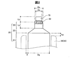
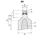
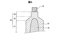
- FIG. 2 to 4 are explanatory views showing a detailed configuration of the center electrode 20.
- FIG. 2 shows a side configuration of a part of the front end side of the center electrode 20
- FIG. 3 shows a cross-sectional configuration passing through a part of the central axis of the front end side of the center electrode 20.
- FIG. 4 shows a cross-sectional configuration before the center electrode 20 and the noble metal tip 70 are joined by laser welding. 2 to 4, the upper side of the figure is the front end side, and the lower side of the figure is the rear end side.
- the center electrode 20 is positioned on the rear end side of the substantially cylindrical small diameter portion 23 having a length along the axial direction of Ls (mm) and a diameter of Ds (mm), and the small diameter portion 23, and having a diameter of Dg. (Mm) (however, Dg> Ds) has a substantially cylindrical large-diameter portion 21, and a small-diameter portion 23 and a connecting portion 22 that connects the large-diameter portion 21.
- the shape of the connecting portion 22 is a tapered shape in which the diameter continuously changes from the boundary position (diameter Ds) with the small diameter portion 23 to the boundary position (diameter Dg) with the large diameter portion 21.
- the center electrode 20 since the center electrode 20 is the structure which has the small diameter part 23, the connection part 22, and the large diameter part 21, it has favorable ignitability.
- the small-diameter portion 23 and the connecting portion 22 of the center electrode 20 are located on the distal end side with respect to the end surface on the distal end side of the insulator 30 (the long leg portion 35). That is, the boundary between the connecting portion 22 and the large diameter portion 21 is located on the distal end side with respect to the end surface on the distal end side of the insulator 30.
- the positional relationship between the center electrode 20 and the insulator 30 is set to such a relationship, the ignitability is improved, which is preferable.
- the distance Lg along the axial direction between the boundary and the front end side end surface is 2 mm. If it is within the range, the decrease in ignitability is slight.
- the clearance X between the insulator 30 (insulator) and the large diameter portion 21 of the center electrode 20 is usually a value exceeding 0 mm. A preferable value of the clearance X will be described later.
- a noble metal tip 70 is joined to the end of the small diameter portion 23 of the center electrode 20 by laser welding.
- the noble metal tip 70 and the small diameter portion 23 are placed in a state where the substantially cylindrical noble metal tip 70 is placed on the end face of the small diameter portion 23.
- a laser is irradiated to the boundary portion. Thereby, as shown in FIGS. 2 and 3, a melting portion 92 is formed at the boundary portion, and the noble metal tip 70 and the center electrode 20 are joined.
- the length of the noble metal tip 70 is increased.
- the length Lc can be measured.
- the precious metal tip 70 is as follows. Is estimated.
- Performance evaluation test A performance evaluation test was conducted on the ignition performance, durability of the noble metal tip 70 and breakage resistance of the center electrode 20 for the spark plug 300 of the present embodiment described above.
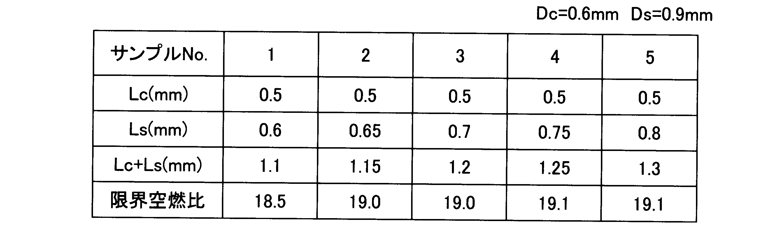
- Table 1 shows the performance evaluation test results regarding the ignitability of the spark plug 300.
- the limit air-fuel ratio at which no misfire occurs was examined for a plurality of samples (samples 1-5) having different lengths Ls of the small diameter portion 23 of the center electrode 20.
- the ignitability of the spark plug 300 is better as the limit air-fuel ratio is larger.
- test conditions are: test method: misfire limit method, engine used: type; inline 4-cylinder DOHC natural intake type, displacement: 1.6 liters, operating condition: rotation speed: 1600 rpm, noble metal tip 70 dimensions: diameter Dc 0.6 mm, length Lc: 0.5 mm, dimensions of the small diameter portion 23: diameter Ds; 0.9 mm, length Ls; 0.6-0.8 mm (depending on the sample), dimensions of the large diameter portion 21: Diameter Dg: 2.6 mm.
- Sample 2-5 in which the sum (Lc + Ls) of the length Ls of the small-diameter portion 23 and the length Lc of the noble metal tip 70 is 1.15 or more has a critical air-fuel ratio of 19 or more, and exhibits good ignitability.
- Sample 1 having a sum (Lc + Ls) of less than 1.15 had a limit air-fuel ratio of less than 19, and good ignitability was not obtained.
- the sum (Lc + Ls) was changed by changing the length Ls of the small-diameter portion 23.
- the sum (Lc + Ls) is changed by changing the length Lc of the noble metal tip 70, the same applies. Test results are expected to be obtained.
- the ignitability of the spark plug 300 depends not on individual values of the length Ls of the small diameter portion 23 and the length Lc of the noble metal tip 70 but on the sum (Lc + Ls) thereof. Therefore, it is preferable that the center electrode 20 of the spark plug 300 is configured to satisfy the following relationship from the viewpoint of ensuring good ignitability of the spark plug 300. Lc + Ls ⁇ 1.15
- the center electrode 20 is more preferably configured to satisfy the following relationship from the viewpoint of ensuring good ignitability and durability. 1.15 ⁇ Lc + Ls ⁇ 3.0 The center electrode 20 is more preferably configured to satisfy the following relationship from the viewpoint of ensuring good ignitability and better durability. 1.15 ⁇ Lc + Ls ⁇ 2.0
- FIG. 6 shows the performance evaluation test results regarding the durability of the spark plug 300.
- the diameter Ds of the small-diameter portion 23 of the center electrode 20 is reduced, the heat drawability from the noble metal tip 70 is deteriorated, so that the consumption of the noble metal tip 70 is increased.
- the performance evaluation test regarding durability the relationship between the diameter Ds of the small diameter portion 23 of the center electrode 20 and the wear of the noble metal tip 70 was examined.
- test method engine fully open endurance test, engine used: type; inline 4-cylinder DOHC natural intake type, displacement: 1.6 liters, operating condition: rotation speed: 5000 rpm O. T.A.
- the diameter Ds of the small diameter portion 23 is 0.6 mm or more (that is, the same value as the diameter Dc of the noble metal tip 70)
- the consumption amount of the noble metal tip 70 is less than 0.1 mm, which is preferable.
- the diameter Ds of the small diameter portion 23 is 1.0 mm (that is, a value 0.4 mm larger than the diameter Dc of the noble metal tip 70) or more, the consumption amount of the noble metal tip 70 is flat even if the diameter Ds is increased. It is.
- the center electrode 20 of the spark plug 300 is preferably configured to satisfy the following relationship from the viewpoint of ensuring good ignitability of the spark plug 300 and suppressing consumption of the noble metal tip 70. Dc ⁇ Ds ⁇ Dc + 0.4
- the small diameter portion occupation ratio (Ls / (Lc + Ls)) represents the ratio of the length Ls of the small diameter portion 23 to the total length of the portion formed by the small diameter portion 23 and the noble metal tip 70 in the center electrode 20. . Since the noble metal tip 70 is formed of a material having a high density, if the sum (Lc + Ls) is the same, the smaller diameter portion occupying ratio (Ls / (Lc + Ls)) is larger, and the smaller diameter portion 23 and the noble metal tip 70 are configured. The lighted part becomes lighter. Therefore, it is considered that the breakage resistance is improved as the small diameter portion occupation ratio (Ls / (Lc + Ls)) is larger.
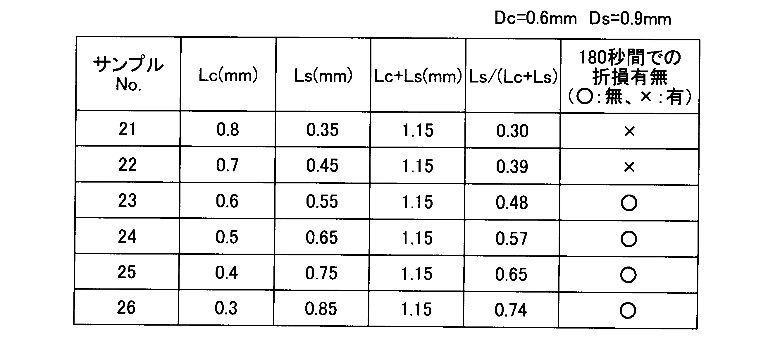
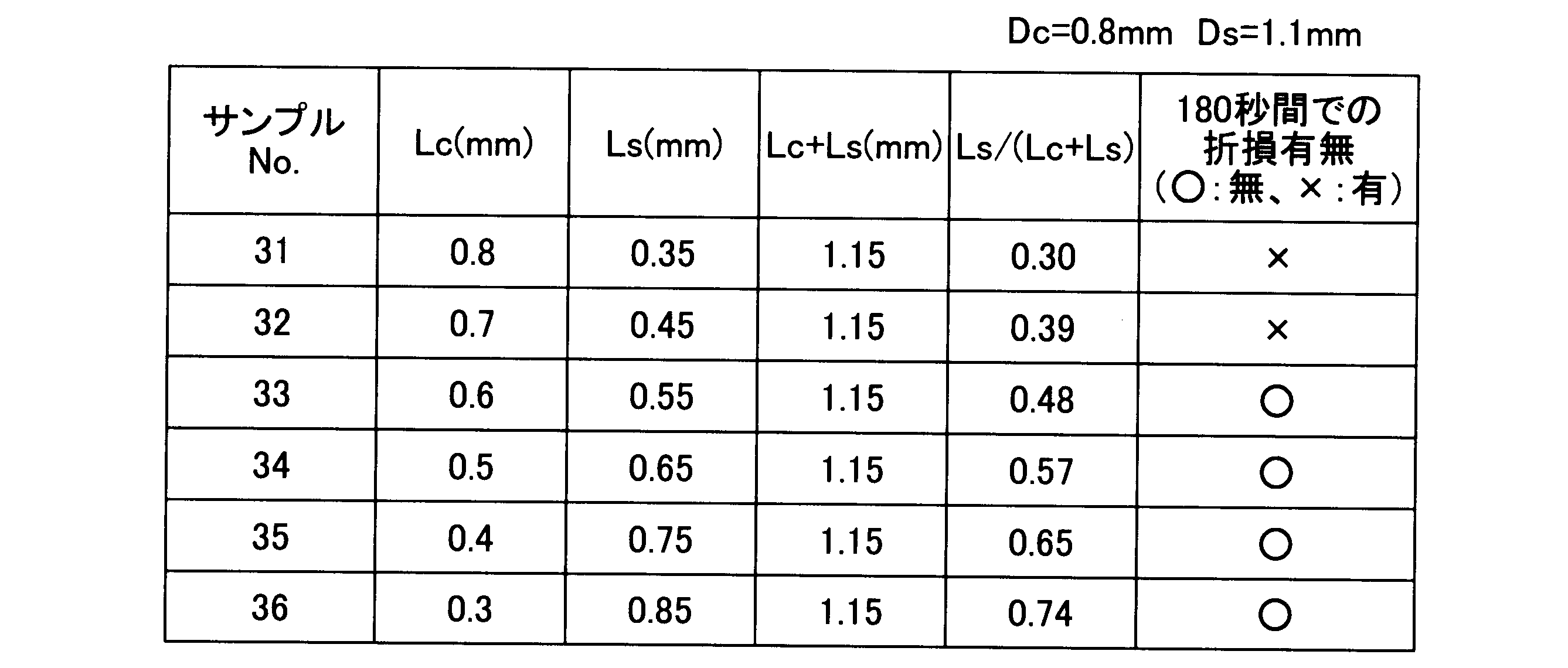
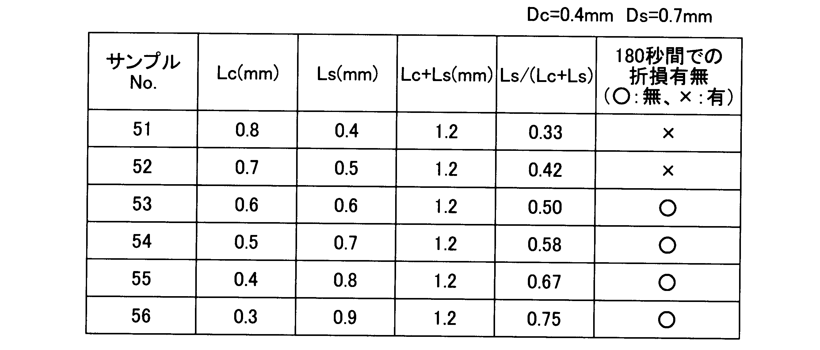
- test method ultrasonic vibration test, vibration direction: radial direction of center electrode 20, vibration frequency: 27.3 kHz, evaluation: presence or absence of breakage of center electrode 20 when vibration is applied for 180 seconds (O: No breakage, x: breakage), dimension of noble metal tip 70: diameter Dc; 0.4-1.0 mm (varies depending on sample), length Lc: 0.3-0.8 mm (varies depending on sample), small diameter portion Dimension 23: Diameter Ds; 0.7-1.3 mm (depending on the sample), Length Ls: 0.35-0.85 mm (depending on the sample), Dimension of the large diameter portion 21: Diameter Dg; 2.6 mm
- the dimension of the melting part 92 is the length along the axial direction of the melting part 92; 0.4 mm.
- Tables 2 to 5 show the evaluation test results when the sum (Lc + Ls) of the length Ls of the small diameter portion 23 and the length Lc of the noble metal tip 70 is 1.15 (mm). Thru
- or Table 9 has shown the evaluation test result in case the said sum (Lc + Ls) is 1.2 (mm).
- the diameter Dc of the noble metal tip 70 and the diameter Ds of the small diameter portion 23 are different from each other.
- the diameter Dc of the noble metal tip 70 and the diameter Ds of the small diameter portion 23 are different from each other.
- the center electrode 20 of the spark plug 300 is more preferably configured to satisfy the following relationship from the viewpoint of improving the breakage resistance and ensuring the durability of the noble metal tip 70. 0.48 ⁇ Ls / (Lc + Ls) ⁇ 0.75
- Second performance evaluation test regarding breakage resistance of the center electrode 20 Tables 10 to 17 show the second performance evaluation test results regarding the breakage resistance of the center electrode 20.
- the second performance evaluation test related to breakage resistance is obtained by changing the vibration applying time from 180 seconds to 300 seconds in the above-described first performance evaluation test related to breakage resistance. Is the same as the first performance evaluation test regarding breakage resistance.
- Tables 10 to 13 show the evaluation test results when the sum (Lc + Ls) of the length Ls of the small diameter portion 23 and the length Lc of the noble metal tip 70 is 1.15 (mm). Thru
- or Table 17 has shown the evaluation test result in case the said sum (Lc + Ls) is 1.2 (mm).
- the diameter Dc of the noble metal tip 70 and the diameter Ds of the small diameter portion 23 are different from each other.
- the diameter Dc of the noble metal tip 70 and the diameter Ds of the small diameter portion 23 are different from each other.
- Samples with small diameter portion occupation ratio (Ls / (Lc + Ls)) of less than 0.61 samples 91, 92, 93, 101, 102, 103, 111, 112, 113, 121, 122, 123, 131, 132, 133) 141, 142, 143, 151, 152, 153, 161, 162, and 163), breakage occurred due to vibration for 300 seconds regardless of the diameter Dc of the noble metal tip 70 and the diameter Ds of the small diameter portion 23.
- the center electrode 20 of the spark plug 300 is more preferably configured to satisfy the following relationship from the viewpoint of further improving breakage resistance and ensuring the durability of the noble metal tip 70. 0.61 ⁇ Ls / (Lc + Ls) ⁇ 0.75
- FIG. 7 shows a third performance evaluation test result regarding the breakage resistance of the center electrode 20.
- the breakage resistance of the center electrode 20 is also affected by the diameter Dg of the large diameter portion 21. In general, the smaller the diameter Dg of the large-diameter portion 21, the greater the vibration of the center electrode 20, so the possibility of breakage of the center electrode 20 increases.
- breakage resistance was examined for a plurality of samples having different diameters Dg of the large diameter portion 21.
- the sample having the small diameter portion occupation ratio of 0.67 is the sample having the small diameter portion occupation ratio of 0.33.
- the time until the center electrode 20 breaks is long (that is, the breakage resistance is high).
- the breakage resistance improvement rate was obtained by changing the small diameter portion occupation ratio from 0.33 to 0.67.
- the rate of improvement in breakage resistance is the time until a sample with a small diameter portion occupation ratio of 0.67 breaks with respect to the time until a sample with a small diameter portion occupation ratio (Ls / (Lc + Ls)) of 0.33 breaks. It is calculated as the ratio.
- the breaking resistance improvement rate is higher as the diameter Dg of the large diameter portion 21 is smaller. Specifically, when the diameter Dg of the large diameter portion 21 is 2.6 mm or less, the breakage resistance improvement rate is 1.1 (10% improvement) or more.
- the center electrode 20 of the spark plug 300 is configured so as to satisfy the following relationship, the fracture resistance due to the configuration in which the small diameter portion occupation ratio (Ls / (Lc + Ls)) is increased as described above. It can be said that the effect of improving the performance is great. Dg ⁇ 2.6
- the breakage resistance improvement rate is 1.3 (30% improvement) or more. Therefore, if the center electrode 20 of the spark plug 300 is configured so as to satisfy the following relationship, the fracture resistance due to the configuration in which the small diameter portion occupation ratio (Ls / (Lc + Ls)) is increased as described above. It can be said that the effect of improving the property is even greater. Dg ⁇ 2.3
- the center electrode 20 of the spark plug 300 is configured to satisfy the following relationship from the viewpoint of improving the breakage resistance and ensuring the workability and durability of the large diameter portion 21. . 1.7 ⁇ Dg ⁇ 2.3
- the breakage resistance improvement rate is 1.8 (80% improvement) or more. Therefore, if the center electrode 20 of the spark plug 300 is configured so as to satisfy the following relationship, the fracture resistance due to the configuration in which the small diameter portion occupation ratio (Ls / (Lc + Ls)) is increased as described above. It can be said that the effect of improving the property is greater. 1.7 ⁇ Dg ⁇ 1.9
- FIG. 8 shows the fourth performance evaluation test result regarding the break resistance of the center electrode 20.
- the breakage resistance of the center electrode 20 is also affected by the clearance X (FIG. 2) between the center electrode 20 and the insulator 30.
- the clearance X (FIG. 2) between the center electrode 20 and the insulator 30.
- the greater the clearance X the greater the vibration of the center electrode 20, so the possibility of breakage of the center electrode 20 increases.
- breakage resistance was examined for two types of samples (comparative sample and example sample) having different clearances X.
- the center electrode 20 without the insulator 30 is used as a sample.
- the center electrode 20 with the insulator 30 is used as a sample. did.
- Other test conditions are the same as those in the third performance evaluation test described above except that the shape of the sample is different.
- the shape of the comparative sample is as follows: dimension of the noble metal tip 70: diameter Dc: 0.6 mm, length Lc: 0.8 mm, dimension of the small diameter portion 23: diameter Ds: 0.9 mm, length Ls: 0.4 mm, large The dimension of the diameter part 21: Diameter Dg; 1.9 mm.
- the shape of the example sample is as follows: dimension of the noble metal tip 70: diameter Dc: 0.6 mm, length Lc: 0.4 mm, dimension of the small diameter portion 23: diameter Ds: 0.9 mm, length Ls: 0.8 mm
- the larger the clearance X the shorter the time until the center electrode 20 breaks (that is, the lower the breakage resistance).
- the test was not performed when the clearance X was zero.
- the breakage time was longer than that when the clearance Lance was 0.03 mm.
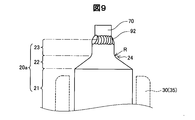
- FIG. 9 is an explanatory diagram showing a preferable shape of the boundary portion between the small diameter portion 23 and the connecting portion 22 of the center electrode 20.
- R sin-called rounded shape
- the boundary portion 24 has a rounded outline
- the boundary between the small diameter portion 23 and the connecting portion 22 is unclear, and shows a gentle curved surface when viewed from the front.
- the boundary between the small-diameter portion 23 and the connecting portion 22 has a clear boundary between the two, and shows a geometric shape in which two straight lines intersect at one point in a front view.
- the boundary portion 24 illustrated in FIG. 9 preferably has such a rounded shape over the entire circumference of the boundary portion 24.
- the radius R of the rounded shape is preferably in the range of 0.1 mm to 0.5 mm. If the boundary portion 24 is formed so as to have such a rounded shape, even when an external force is applied to the center electrode 20, the deflection of the small diameter portion 23 and the connecting portion 22 can be suppressed to be small.
- the spark plug 300 includes the center electrode 20, and the center electrode 20 has a diameter smaller than that of the small diameter portion 23 in which the noble metal tip 70 is joined to the tip by laser welding.
- the large-diameter portion 21 having a large diameter and the connecting portion 22 that connects the small-diameter portion 23 and the large-diameter portion 21 are provided. If such a spark plug 300 is configured to satisfy the following formulas (1) to (3), by satisfying the following formula (2), the durability of the center electrode 20 can be ensured while ensuring good ignitability.
- the center electrode 20 having a small diameter Dg of the large-diameter portion 21 that tends to be low in breakage resistance as shown in the following formula (1) by using the following formula (3) can be suppressed.
- Lc is the axial length of the noble metal tip 70
- Ls is the axial length of the small diameter portion 23. Dg ⁇ 2.6 (1) 1.15 ⁇ Lc + Ls ⁇ 3.0 (2) 0.48 ⁇ Ls / (Lc + Ls) ⁇ 0.75 (3)
- the spark plug 300 is further configured to satisfy the following expression (4), the weight of the portion formed by the noble metal tip 70 and the small diameter portion 23 located at the tip of the center electrode 20 can be further reduced. Thus, the breakage resistance of the center electrode 20 can be further improved. 0.61 ⁇ Ls / (Lc + Ls) ⁇ 0.75 (4)
- the spark plug 300 is further configured to satisfy the following formula (5), the diameter Ds of the small-diameter portion 23 is prevented from becoming excessively large, and the small-diameter portion 23 is secured while ensuring good ignitability. It is possible to suppress heat consumption from the noble metal tip 70 by securing heat from the noble metal tip 70 to some extent.
- Dc is the diameter of the noble metal tip 70
- Ds is the diameter of the small diameter portion 23.
- the spark plug 300 is further configured to satisfy the following formula (6), the diameter Dg of the large diameter portion 21 becomes excessively small, which makes it difficult to process or decreases durability. While avoiding, it is possible to improve the breakage resistance of the center electrode 20 having a small diameter Dg of the large diameter portion 21 that tends to have low breakage resistance. 1.7 ⁇ Dg ⁇ 2.3 (6)
- spark plug 300 is further configured to satisfy the following formula (7), even if the center electrode 20 having a smaller diameter Dg of the large-diameter portion 21 that tends to have lower breakage resistance is used, The breakage resistance of the center electrode 20 can be improved. 1.7 ⁇ Dg ⁇ 1.9 (7)
- the structure of the center electrode can be obtained by further satisfying the following formula (8).
- the breakage resistance can be further improved. 0.03 ⁇ X ⁇ 0.15 (8)
- the small-diameter portion 23 of the center electrode 20 of the spark plug 300 and the boundary portion 24 of the connecting portion 22 have a rounded outline, even when an external force is applied to the central electrode 20, the small-diameter portion 23 is connected. The shake of the part 22 can be suppressed small.
- the configuration of the spark plug 300 in the above embodiment is merely an example, and can be variously modified.
- the material forming each component of the spark plug 300 is not limited to the material described in the above embodiment.
- the center electrode 20 is taken as the 2 layer structure of the coating
- tip 70 is a flat shape substantially perpendicular
- the boundary surface for determining the length Ls of the small diameter portion 23 and the length Lc of the noble metal tip 70 is the most distal end in the small diameter portion 23. It is assumed that the flat surface passes through the portion located on the side and is substantially perpendicular to the central axis of the spark plug 300.
- the present invention is not limited to the above-described embodiments and modifications, and can be realized with various configurations without departing from the spirit thereof.
- the technical features in the embodiments and the modifications corresponding to the technical features in each embodiment described in the summary section of the invention are to solve some or all of the above-described problems, or In order to achieve part or all of the effects, replacement or combination can be performed as appropriate. Further, if the technical feature is not described as essential in the present specification, it can be deleted as appropriate.
Abstract
Description
A-1.スパークプラグの構成:
図1は、本発明の実施形態におけるスパークプラグ300の構成を示す説明図である。図1において、スパークプラグ300の中心軸である軸線OLの右側にはスパークプラグ300の側面構成を示しており、軸線OLの左側にはスパークプラグ300の中心軸を通る断面構成を示している。なお、以下の説明では、軸線OLに沿って、後述する接地電極10が配置されている側(図1の下方側)を先端側と呼び、後述する端子金具40が配置されている側(図1の上方側)を後端側と呼ぶ。 A. Embodiment:
A-1. Spark plug configuration:
FIG. 1 is an explanatory diagram showing a configuration of a
図2ないし図4は、中心電極20の詳細構成を示す説明図である。図2には、中心電極20における先端側の一部の側面構成を示しており、図3には、中心電極20における先端側の一部の中心軸を通る断面構成を示している。また、図4には、中心電極20と貴金属チップ70とをレーザー溶接によって接合する前の断面構成を示している。なお、図2ないし図4では、図の上方側が先端側であり、図の下方側が後端側である。 A-2. Detailed configuration of the center electrode:
2 to 4 are explanatory views showing a detailed configuration of the
以上説明した本実施形態のスパークプラグ300を対象に、着火性、貴金属チップ70の耐久性および中心電極20の耐折損性について性能評価試験を行った。 A-3. Performance evaluation test:
A performance evaluation test was conducted on the ignition performance, durability of the
スパークプラグ300の着火性に関する性能評価試験結果を表1に示す。着火性に関する性能評価試験では、中心電極20の小径部23の長さLsを異ならせた複数のサンプル(サンプル1-5)について、失火しない限界の空燃比を調べた。限界空燃比の値が大きいほど、スパークプラグ300の着火性は良い。詳細な試験条件は、試験方法:失火限界法、使用エンジン:タイプ;直列4気筒DOHC自然吸気型、排気量;1.6リットル、運転条件:回転数;1600rpm、貴金属チップ70の寸法:直径Dc;0.6mm、長さLc;0.5mm、小径部23の寸法:直径Ds;0.9mm、長さLs;0.6-0.8mm(サンプルによって異なる)、大径部21の寸法:直径Dg;2.6mm、である。 A-3-1. Ignition performance evaluation test:
Table 1 shows the performance evaluation test results regarding the ignitability of the
Lc+Ls≧1.15 Sample 2-5 in which the sum (Lc + Ls) of the length Ls of the small-
Lc + Ls ≧ 1.15
1.15≦Lc+Ls≦3.0
また、中心電極20は、良好な着火性とより良好な耐久性とを確保するという観点から、下記の関係を満たすように構成されていることがさらに好ましい。
1.15≦Lc+Ls≦2.0 However, if the sum (Lc + Ls) of the length Ls of the small-
1.15 ≦ Lc + Ls ≦ 3.0
The
1.15 ≦ Lc + Ls ≦ 2.0
スパークプラグ300の耐久性に関する性能評価試験結果を図6に示す。中心電極20の小径部23の直径Dsを小さくするほど、貴金属チップ70からの熱引き性が悪くなるため、貴金属チップ70の消耗が大きくなる。耐久性に関する性能評価試験では、中心電極20の小径部23の直径Dsと、貴金属チップ70の消耗との関係について調べた。詳細な試験条件は、試験方法:エンジン全開耐久試験、使用エンジン:タイプ;直列4気筒DOHC自然吸気型、排気量;1.6リットル、運転条件:回転数;5000rpm W.O.T.、100時間運転、大径部21の温度;摂氏800度、貴金属チップ70(Ir-Pt合金)の寸法:直径Dc;0.6mm、長さLc;0.5mm、小径部23の寸法:直径Ds;0.5-1.2mm(サンプルによって異なる)、長さLs;0.65mm、である。 A-3-2. Performance evaluation test for durability:
FIG. 6 shows the performance evaluation test results regarding the durability of the
Dc≦Ds≦Dc+0.4 As shown in FIG. 6, the larger the diameter Ds of the small-
Dc ≦ Ds ≦ Dc + 0.4
中心電極20の耐折損性に関する第1の性能評価試験結果を表2ないし表9に示す。耐折損性に関する第1の性能評価試験では、小径部23の長さLsと貴金属チップ70の長さLcとの和(Lc+Ls)に対する小径部23の長さLsの比(Ls/(Lc+Ls)、以下「小径部占有比」と呼ぶ)を異ならせた複数のサンプルについて、耐折損性を調べた。なお、各サンプルの小径部占有比を異ならせるために、和(Lc+Ls)を1.15(mm)(表2ないし表5)または1.2(mm)(表6ないし表9)に固定しつつ、各サンプルの小径部23の長さLsと貴金属チップ70の長さLcとを異ならせた。 A-3-3. First performance evaluation test regarding breakage resistance of the center electrode 20:
Tables 1 to 9 show the first performance evaluation test results regarding the breakage resistance of the


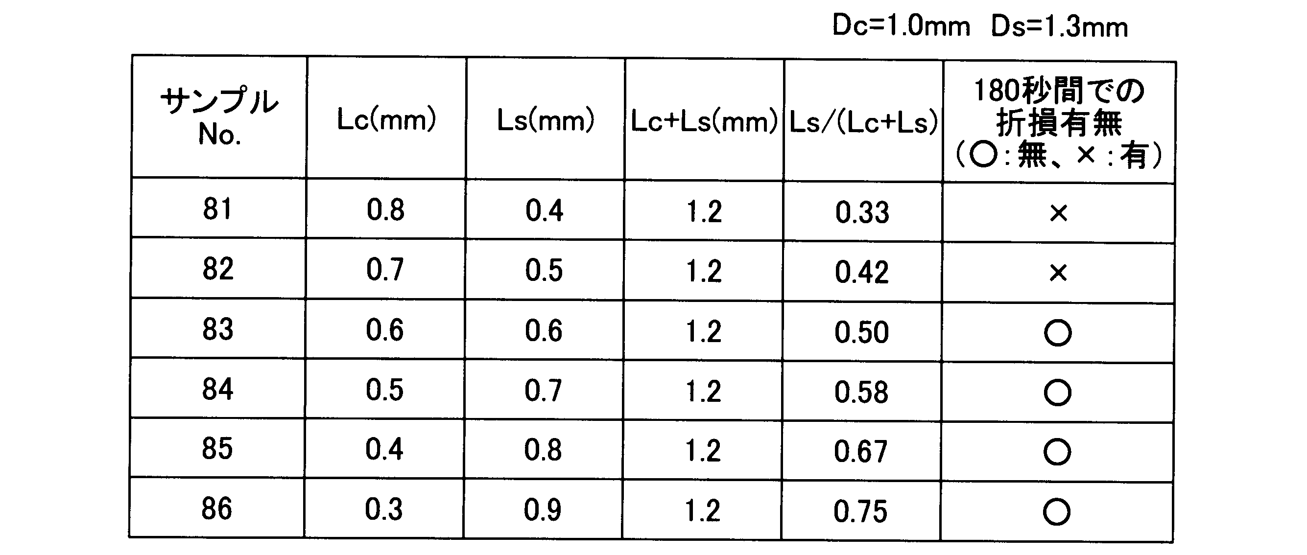
Ls/(Lc+Ls)≧0.48 Samples with small diameter portion occupation ratio (Ls / (Lc + Ls)) of less than 0.48 (
Ls / (Lc + Ls) ≧ 0.48
0.48≦Ls/(Lc+Ls)≦0.75 However, if the small diameter portion occupation ratio (Ls / (Lc + Ls)) is too large, the length Lc of the
0.48 ≦ Ls / (Lc + Ls) ≦ 0.75
中心電極20の耐折損性に関する第2の性能評価試験結果を表10ないし表17に示す。耐折損性に関する第2の性能評価試験は、上述した耐折損性に関する第1の性能評価試験において、振動を与える時間を180秒間から300秒間に変更したものであり、その他の方法・条件等については耐折損性に関する第1の性能評価試験と同じである。 A-3-4. Second performance evaluation test regarding breakage resistance of the center electrode 20:
Tables 10 to 17 show the second performance evaluation test results regarding the breakage resistance of the


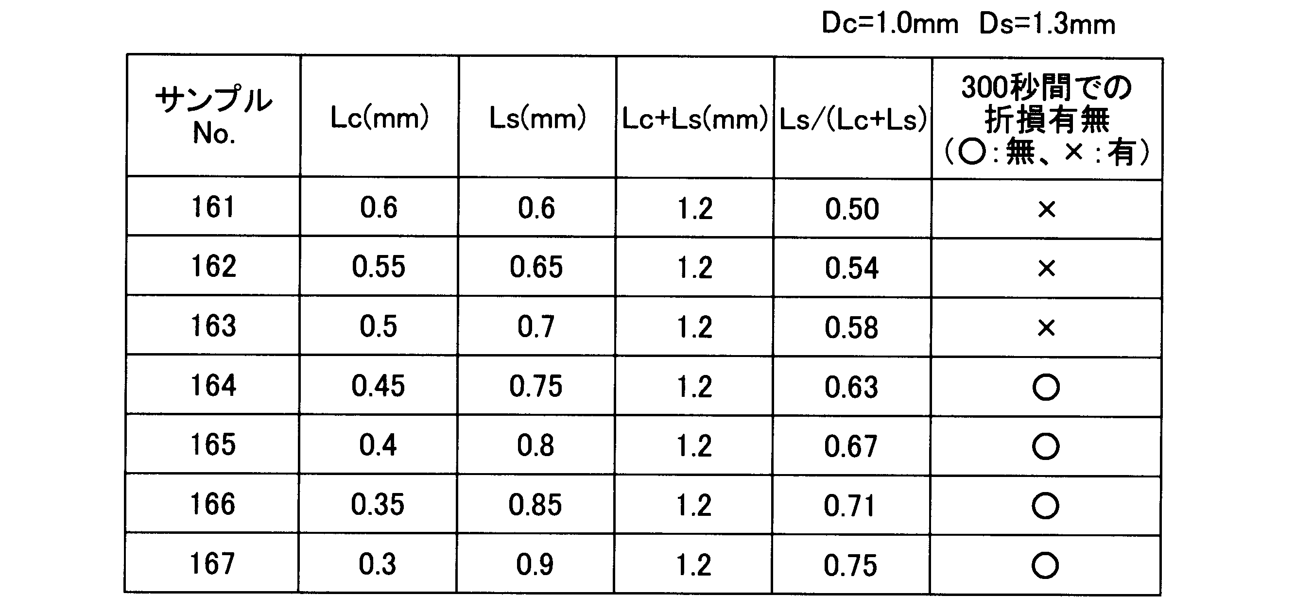
0.61≦Ls/(Lc+Ls)≦0.75 Samples with small diameter portion occupation ratio (Ls / (Lc + Ls)) of less than 0.61 (
0.61 ≦ Ls / (Lc + Ls) ≦ 0.75
中心電極20の耐折損性に関する第3の性能評価試験結果を図7に示す。中心電極20の耐折損性は、大径部21の直径Dgにも影響される。一般に、大径部21の直径Dgが小さいほど、中心電極20の振動が大きくなるため、中心電極20の折損の可能性は高くなる。耐折損性に関する第3の性能評価試験では、大径部21の直径Dgが互いに異なる複数のサンプルについて、耐折損性を調べた。具体的には、バーナー冷熱試験(バーナーによる2分間加熱(摂氏900度)と1分間冷却とを1000サイクル繰り返す試験)の後に、上述した耐折損性に関する第1,2の性能評価試験と同様の超音波振動試験を行った。ただし、耐折損性に関する第3の性能評価試験では、中心電極20の折損が発生するまで振動を与え続けた。詳細な試験条件は、貴金属チップ70の寸法:直径Dc;0.6mm、長さLc;0.8mmまたは0.4mm(サンプルによって異なる)、小径部23の寸法:直径Ds;0.9mm、長さLs;0.4mmまたは0.8mm(サンプルによって異なる)、大径部21の寸法:直径Dg;1.7-2.6mm(サンプルによって異なる)、である。 A-3-5. Third performance evaluation test regarding breakage resistance of the center electrode 20:
FIG. 7 shows a third performance evaluation test result regarding the breakage resistance of the
Dg≦2.6 In the test, samples having the same diameter Dg of the
Dg ≦ 2.6
Dg≦2.3 Moreover, if the diameter Dg of the
Dg ≦ 2.3
1.7≦Dg≦2.3 However, if the diameter Dg of the
1.7 ≦ Dg ≦ 2.3
1.7≦Dg≦1.9 Moreover, according to FIG. 7, if the diameter Dg of the
1.7 ≦ Dg ≦ 1.9
中心電極20の耐折損性に関する第4の性能評価試験結果を図8に示す。中心電極20の耐折損性は、中心電極20と絶縁碍子30との間のクリアランスX(図2)にも影響される。一般に、クリアランスXが大きいほど、中心電極20の振動が大きくなるため、中心電極20の折損の可能性は高くなる。耐折損性に関する第4の性能評価試験では、クリアランスXが互いに異なる2種類のサンプル(比較例サンプル及び実施例サンプル)について、耐折損性を調べた。上述した第3の性能評価試験は、絶縁碍子30が付されていない中心電極20をサンプルとして使用していたが、第4の性能評価試験では、絶縁碍子30付きの中心電極20をサンプルとして使用した。その他の試験条件は、サンプルの形状が異なる点以外は、上述した第3の性能評価試験と同じである。比較例サンプルの形状は、貴金属チップ70の寸法:直径Dc;0.6mm、長さLc;0.8mm、小径部23の寸法:直径Ds;0.9mm、長さLs;0.4mm、大径部21の寸法:直径Dg;1.9mm、である。また、実施例サンプルの形状は、貴金属チップ70の寸法:直径Dc;0.6mm、長さLc;0.4mm、小径部23の寸法:直径Ds;0.9mm、長さLs;0.8mm、大径部21の寸法:直径Dg;1.9mm、である。なお、図8の実施例サンプルの寸法は、図7において黒三角のプロットのうちでDg=1.9mmで示されるサンプルの寸法に対応している。 A-3-6. Fourth performance evaluation test regarding breakage resistance of the center electrode 20:
FIG. 8 shows the fourth performance evaluation test result regarding the break resistance of the
0.03≦X≦0.15 As shown in FIG. 8, as a general trend, the larger the clearance X, the shorter the time until the
0.03 ≦ X ≦ 0.15
図9は、中心電極20の小径部23と連結部22の境界部分の好ましい形状を示す説明図である。図2と図9とを比較すれば理解できるように、図9のスパークプラグでは、小径部23と連結部22の境界部分24にR(いわゆる丸め形状)が付されている。換言すれば、この境界部分24は、丸められた輪郭を有しており、小径部23と連結部22の境目が不明瞭であって、正面視ではなだらかな曲面を示す。一方、図2に示したスパークプラグでは、小径部23と連結部22の境界部は、これらの両者の境目が明瞭であり、正面視では2つの直線が一点で交わる幾何学的な形状を示す。なお、図9に示した境界部分24は、境界部分24の全周に亘ってこのような丸め形状を有することが好ましい。また、丸め形状の半径Rは、0.1mm以上0.5mm以下の範囲とすることが好ましい。このような丸め形状を有するように境界部分24を形成すれば、中心電極20に外力が掛かった場合にも、小径部23と連結部22の振れを小さく抑えることができる。 A-4. Other:
FIG. 9 is an explanatory diagram showing a preferable shape of the boundary portion between the
Dg≦2.6・・・(1)
1.15≦Lc+Ls≦3.0・・・(2)
0.48≦Ls/(Lc+Ls)≦0.75・・・(3) As described above, the
Dg ≦ 2.6 (1)
1.15 ≦ Lc + Ls ≦ 3.0 (2)
0.48 ≦ Ls / (Lc + Ls) ≦ 0.75 (3)
0.61≦Ls/(Lc+Ls)≦0.75・・・(4) Further, if the
0.61 ≦ Ls / (Lc + Ls) ≦ 0.75 (4)
Dc≦Ds≦Dc+0.4・・・(5) If the
Dc ≦ Ds ≦ Dc + 0.4 (5)
1.7≦Dg≦2.3・・・(6) Further, if the
1.7 ≦ Dg ≦ 2.3 (6)
1.7≦Dg≦1.9・・・(7) Further, if the
1.7 ≦ Dg ≦ 1.9 (7)
0.03≦X≦0.15・・・(8) Further, when the clearance between the
0.03 ≦ X ≦ 0.15 (8)
上記実施形態におけるスパークプラグ300の構成は、あくまで一例であり、種々変形可能である。例えば、スパークプラグ300の各構成部品を形成する材料は、上記実施形態に記載された材料に限られない。また、上記実施形態では、中心電極20は、被覆部分25と芯部分26との2層構造であるとしているが、中心電極20は単層構造であってもよいし、3層以上の構造であってもよい。 B. Variation:
The configuration of the
11…自由端部
12…基端部
20…中心電極
21…大径部
22…連結部
23…小径部
24…境界部分
25…被覆部分
26…芯部分
30…絶縁碍子
31…軸孔
32…中央胴部
33…後端側胴部
34…先端側胴部
35…脚長部
40…端子金具
50…主体金具
51…工具係合部
52…ネジ部
53…後端部
54…座部
57…端面
59…ガスケット
61…セラミック抵抗
62…シール体
70…貴金属チップ
92…溶融部
201…ネジ孔
300…スパークプラグ
500…エンジンヘッド
OL…軸線 DESCRIPTION OF
Claims (7)
- 先端にレーザー溶接によって貴金属チップが接合された小径部と、前記小径部より径の大きい大径部と、前記小径部と前記大径部とを連結する連結部と、を有する中心電極を備えるスパークプラグにおいて、
前記大径部の径をDg(mm)とし、前記スパークプラグの軸方向に沿った前記貴金属チップの長さをLc(mm)とし、前記小径部の長さをLs(mm)としたときに、式(1)-(3)を満たすことを特徴とする、スパークプラグ。
Dg≦2.6・・・(1)
1.15≦Lc+Ls≦3.0・・・(2)
0.48≦Ls/(Lc+Ls)≦0.75・・・(3) A spark comprising a center electrode having a small diameter portion having a noble metal tip joined to the tip thereof by laser welding, a large diameter portion having a larger diameter than the small diameter portion, and a connecting portion connecting the small diameter portion and the large diameter portion. In the plug,
When the diameter of the large diameter portion is Dg (mm), the length of the noble metal tip along the axial direction of the spark plug is Lc (mm), and the length of the small diameter portion is Ls (mm) A spark plug characterized by satisfying the formulas (1) to (3):
Dg ≦ 2.6 (1)
1.15 ≦ Lc + Ls ≦ 3.0 (2)
0.48 ≦ Ls / (Lc + Ls) ≦ 0.75 (3) - 請求項1に記載のスパークプラグにおいて、
式(4)を満たすことを特徴とする、スパークプラグ。
0.61≦Ls/(Lc+Ls)≦0.75・・・(4) The spark plug according to claim 1, wherein
A spark plug characterized by satisfying the formula (4).
0.61 ≦ Ls / (Lc + Ls) ≦ 0.75 (4) - 請求項1または請求項2に記載のスパークプラグにおいて、
前記貴金属チップの径をDc(mm)とし、前記小径部の径をDs(mm)としたときに、式(5)を満たすことを特徴とする、スパークプラグ。
Dc≦Ds≦Dc+0.4・・・(5) The spark plug according to claim 1 or 2,
A spark plug characterized by satisfying the formula (5) when the diameter of the noble metal tip is Dc (mm) and the diameter of the small diameter portion is Ds (mm).
Dc ≦ Ds ≦ Dc + 0.4 (5) - 請求項1から請求項3までのいずれか一項に記載のスパークプラグにおいて、
式(6)を満たすことを特徴とする、スパークプラグ。
1.7≦Dg≦2.3・・・(6) In the spark plug according to any one of claims 1 to 3,
A spark plug characterized by satisfying the formula (6).
1.7 ≦ Dg ≦ 2.3 (6) - 請求項4に記載のスパークプラグにおいて、
式(7)を満たすことを特徴とする、スパークプラグ。
1.7≦Dg≦1.9・・・(7) The spark plug according to claim 4, wherein
A spark plug characterized by satisfying the formula (7).
1.7 ≦ Dg ≦ 1.9 (7) - 請求項1~5のいずれか一項に記載のスパークプラグにおいて、
前記中心電極と前記スパークプラグの絶縁体との間のクリアランスをX(mm)としたときに、式(8)を満たすことを特徴とする、スパークプラグ。
0.03≦X≦0.15・・・(8) The spark plug according to any one of claims 1 to 5,
A spark plug characterized by satisfying the formula (8) when a clearance between the center electrode and the insulator of the spark plug is X (mm).
0.03 ≦ X ≦ 0.15 (8) - 請求項1~6のいずれか一項に記載のスパークプラグにおいて、
前記中心電極の前記小径部と前記連結部の境界部分が、丸められた輪郭を有することを特徴とする、スパークプラグ。 The spark plug according to any one of claims 1 to 6,
The spark plug according to claim 1, wherein a boundary portion between the small diameter portion and the connecting portion of the center electrode has a rounded outline.
Priority Applications (4)
| Application Number | Priority Date | Filing Date | Title |
|---|---|---|---|
| JP2014542630A JP5933154B2 (en) | 2013-04-17 | 2014-04-01 | Spark plug |
| CN201480021947.9A CN105164876A (en) | 2013-04-17 | 2014-04-01 | Spark plug |
| EP14785717.1A EP2988382B1 (en) | 2013-04-17 | 2014-04-01 | Spark plug |
| US14/779,752 US9525271B2 (en) | 2013-04-17 | 2014-04-01 | Spark plug |
Applications Claiming Priority (2)
| Application Number | Priority Date | Filing Date | Title |
|---|---|---|---|
| JP2013-086562 | 2013-04-17 | ||
| JP2013086562 | 2013-04-17 |
Publications (1)
| Publication Number | Publication Date |
|---|---|
| WO2014171088A1 true WO2014171088A1 (en) | 2014-10-23 |
Family
ID=51731051
Family Applications (1)
| Application Number | Title | Priority Date | Filing Date |
|---|---|---|---|
| PCT/JP2014/001906 WO2014171088A1 (en) | 2013-04-17 | 2014-04-01 | Spark plug |
Country Status (5)
| Country | Link |
|---|---|
| US (1) | US9525271B2 (en) |
| EP (1) | EP2988382B1 (en) |
| JP (1) | JP5933154B2 (en) |
| CN (1) | CN105164876A (en) |
| WO (1) | WO2014171088A1 (en) |
Families Citing this family (1)
| Publication number | Priority date | Publication date | Assignee | Title |
|---|---|---|---|---|
| JP6427133B2 (en) * | 2016-03-29 | 2018-11-21 | 日本特殊陶業株式会社 | Spark plug |
Citations (10)
| Publication number | Priority date | Publication date | Assignee | Title |
|---|---|---|---|---|
| JPS6163788U (en) * | 1984-10-02 | 1986-04-30 | ||
| JPH01109675A (en) * | 1987-10-22 | 1989-04-26 | Nippon Denso Co Ltd | Spark plug for internal combustion engine |
| JPH03176978A (en) | 1989-12-05 | 1991-07-31 | Ngk Spark Plug Co Ltd | Electrode for spark plug |
| JPH05335066A (en) * | 1992-06-01 | 1993-12-17 | Nippondenso Co Ltd | Spark plug for internal combustion engine |
| JPH0636856A (en) | 1992-06-17 | 1994-02-10 | Ngk Spark Plug Co Ltd | Spark plug |
| JP2000208235A (en) | 1998-11-11 | 2000-07-28 | Ngk Spark Plug Co Ltd | Spark plug |
| JP2004207219A (en) | 2002-12-10 | 2004-07-22 | Denso Corp | Spark plug |
| JP2005150011A (en) | 2003-11-19 | 2005-06-09 | Ngk Spark Plug Co Ltd | Spark plug for internal combustion engine |
| JP2011034826A (en) | 2009-08-03 | 2011-02-17 | Ngk Spark Plug Co Ltd | Spark plug |
| JP2012182118A (en) * | 2011-02-10 | 2012-09-20 | Ngk Spark Plug Co Ltd | Spark plug |
Family Cites Families (5)
| Publication number | Priority date | Publication date | Assignee | Title |
|---|---|---|---|---|
| JP3079383B2 (en) | 1990-09-29 | 2000-08-21 | 日本特殊陶業株式会社 | Spark plug for internal combustion engine |
| JP4302224B2 (en) | 1999-02-22 | 2009-07-22 | 日本特殊陶業株式会社 | Spark plug |
| FR2860654B1 (en) * | 2003-09-11 | 2011-04-22 | Ngk Spark Plug Co | IGNITION CANDLE FOR HIGH TEMPERATURES |
| US20050168121A1 (en) * | 2004-02-03 | 2005-08-04 | Federal-Mogul Ignition (U.K.) Limited | Spark plug configuration having a metal noble tip |
| DE102011083640A1 (en) * | 2011-09-28 | 2013-03-28 | Robert Bosch Gmbh | Improved spark plug |
-
2014
- 2014-04-01 EP EP14785717.1A patent/EP2988382B1/en active Active
- 2014-04-01 US US14/779,752 patent/US9525271B2/en active Active
- 2014-04-01 WO PCT/JP2014/001906 patent/WO2014171088A1/en active Application Filing
- 2014-04-01 CN CN201480021947.9A patent/CN105164876A/en active Pending
- 2014-04-01 JP JP2014542630A patent/JP5933154B2/en active Active
Patent Citations (10)
| Publication number | Priority date | Publication date | Assignee | Title |
|---|---|---|---|---|
| JPS6163788U (en) * | 1984-10-02 | 1986-04-30 | ||
| JPH01109675A (en) * | 1987-10-22 | 1989-04-26 | Nippon Denso Co Ltd | Spark plug for internal combustion engine |
| JPH03176978A (en) | 1989-12-05 | 1991-07-31 | Ngk Spark Plug Co Ltd | Electrode for spark plug |
| JPH05335066A (en) * | 1992-06-01 | 1993-12-17 | Nippondenso Co Ltd | Spark plug for internal combustion engine |
| JPH0636856A (en) | 1992-06-17 | 1994-02-10 | Ngk Spark Plug Co Ltd | Spark plug |
| JP2000208235A (en) | 1998-11-11 | 2000-07-28 | Ngk Spark Plug Co Ltd | Spark plug |
| JP2004207219A (en) | 2002-12-10 | 2004-07-22 | Denso Corp | Spark plug |
| JP2005150011A (en) | 2003-11-19 | 2005-06-09 | Ngk Spark Plug Co Ltd | Spark plug for internal combustion engine |
| JP2011034826A (en) | 2009-08-03 | 2011-02-17 | Ngk Spark Plug Co Ltd | Spark plug |
| JP2012182118A (en) * | 2011-02-10 | 2012-09-20 | Ngk Spark Plug Co Ltd | Spark plug |
Also Published As
| Publication number | Publication date |
|---|---|
| CN105164876A (en) | 2015-12-16 |
| US20160105000A1 (en) | 2016-04-14 |
| US9525271B2 (en) | 2016-12-20 |
| EP2988382B1 (en) | 2018-07-11 |
| EP2988382A4 (en) | 2016-11-30 |
| JP5933154B2 (en) | 2016-06-08 |
| JPWO2014171088A1 (en) | 2017-02-16 |
| EP2988382A1 (en) | 2016-02-24 |
Similar Documents
| Publication | Publication Date | Title |
|---|---|---|
| JP5414896B2 (en) | Spark plug | |
| US6798124B2 (en) | Structure of spark plug designed to provide high thermal resistance and durability | |
| JP2007242588A (en) | Spark plug for internal combustion engine | |
| JP5099858B2 (en) | Spark plug and method of manufacturing spark plug | |
| JP2005129377A (en) | Spark plug | |
| WO2010038467A1 (en) | Spark plug | |
| JP4430724B2 (en) | Spark plug | |
| JP2007213927A (en) | Sparkplug for internal combustion engine | |
| JP5933154B2 (en) | Spark plug | |
| JP5032556B2 (en) | Spark plug | |
| WO2009116553A1 (en) | Spark plug | |
| EP3065238B1 (en) | Spark plug | |
| JP6077091B2 (en) | Spark plug | |
| JP7316252B2 (en) | Spark plug | |
| JP5057073B2 (en) | Spark plug | |
| JP5721680B2 (en) | Spark plug | |
| JP7109146B2 (en) | Spark plug | |
| JP4377177B2 (en) | Spark plug for internal combustion engine | |
| JP2005353606A (en) | Spark plug | |
| JP2005183189A (en) | Spark plug | |
| JP2016146274A (en) | Ignition plug for internal-combustion engine | |
| EP3046193B1 (en) | Spark plug | |
| JP2021082538A (en) | Spark plug | |
| WO2016132687A1 (en) | Spark plug | |
| JP2009272044A (en) | Spark plug |
Legal Events
| Date | Code | Title | Description |
|---|---|---|---|
| WWE | Wipo information: entry into national phase |
Ref document number: 201480021947.9 Country of ref document: CN |
|
| ENP | Entry into the national phase |
Ref document number: 2014542630 Country of ref document: JP Kind code of ref document: A |
|
| 121 | Ep: the epo has been informed by wipo that ep was designated in this application |
Ref document number: 14785717 Country of ref document: EP Kind code of ref document: A1 |
|
| WWE | Wipo information: entry into national phase |
Ref document number: 14779752 Country of ref document: US |
|
| WWE | Wipo information: entry into national phase |
Ref document number: IDP00201506202 Country of ref document: ID |
|
| NENP | Non-entry into the national phase |
Ref country code: DE |
|
| WWE | Wipo information: entry into national phase |
Ref document number: 2014785717 Country of ref document: EP |