WO2014171017A1 - Internal combustion engine and drive system - Google Patents
Internal combustion engine and drive system Download PDFInfo
- Publication number
- WO2014171017A1 WO2014171017A1 PCT/JP2013/061679 JP2013061679W WO2014171017A1 WO 2014171017 A1 WO2014171017 A1 WO 2014171017A1 JP 2013061679 W JP2013061679 W JP 2013061679W WO 2014171017 A1 WO2014171017 A1 WO 2014171017A1
- Authority
- WO
- WIPO (PCT)
- Prior art keywords
- valve
- cylinder
- stroke
- air
- internal combustion
- Prior art date
Links
Images


Classifications
-
- F—MECHANICAL ENGINEERING; LIGHTING; HEATING; WEAPONS; BLASTING
- F01—MACHINES OR ENGINES IN GENERAL; ENGINE PLANTS IN GENERAL; STEAM ENGINES
- F01L—CYCLICALLY OPERATING VALVES FOR MACHINES OR ENGINES
- F01L1/00—Valve-gear or valve arrangements, e.g. lift-valve gear
- F01L1/12—Transmitting gear between valve drive and valve
- F01L1/18—Rocking arms or levers
- F01L1/185—Overhead end-pivot rocking arms
-
- F—MECHANICAL ENGINEERING; LIGHTING; HEATING; WEAPONS; BLASTING
- F01—MACHINES OR ENGINES IN GENERAL; ENGINE PLANTS IN GENERAL; STEAM ENGINES
- F01L—CYCLICALLY OPERATING VALVES FOR MACHINES OR ENGINES
- F01L1/00—Valve-gear or valve arrangements, e.g. lift-valve gear
- F01L1/02—Valve drive
- F01L1/04—Valve drive by means of cams, camshafts, cam discs, eccentrics or the like
- F01L1/047—Camshafts
- F01L1/053—Camshafts overhead type
-
- F—MECHANICAL ENGINEERING; LIGHTING; HEATING; WEAPONS; BLASTING
- F02—COMBUSTION ENGINES; HOT-GAS OR COMBUSTION-PRODUCT ENGINE PLANTS
- F02B—INTERNAL-COMBUSTION PISTON ENGINES; COMBUSTION ENGINES IN GENERAL
- F02B33/00—Engines characterised by provision of pumps for charging or scavenging
- F02B33/02—Engines with reciprocating-piston pumps; Engines with crankcase pumps
- F02B33/06—Engines with reciprocating-piston pumps; Engines with crankcase pumps with reciprocating-piston pumps other than simple crankcase pumps
-
- F—MECHANICAL ENGINEERING; LIGHTING; HEATING; WEAPONS; BLASTING
- F02—COMBUSTION ENGINES; HOT-GAS OR COMBUSTION-PRODUCT ENGINE PLANTS
- F02B—INTERNAL-COMBUSTION PISTON ENGINES; COMBUSTION ENGINES IN GENERAL
- F02B33/00—Engines characterised by provision of pumps for charging or scavenging
- F02B33/44—Passages conducting the charge from the pump to the engine inlet, e.g. reservoirs
-
- F—MECHANICAL ENGINEERING; LIGHTING; HEATING; WEAPONS; BLASTING
- F02—COMBUSTION ENGINES; HOT-GAS OR COMBUSTION-PRODUCT ENGINE PLANTS
- F02B—INTERNAL-COMBUSTION PISTON ENGINES; COMBUSTION ENGINES IN GENERAL
- F02B75/00—Other engines
- F02B75/02—Engines characterised by their cycles, e.g. six-stroke
Definitions
- cams 120, 130, 140, and 150 are provided at the ends of the above-described valves 20, 30, 40, and 50 through rocker arms 20A, 30A, 40A, and 50A, respectively. Are in contact with each other, and the opening / closing operation described later is performed by the rotation of the cams.
- valve drive mechanisms Various types of these valve drive mechanisms are known, and any of them may be applied.
- a fuel ignition plug 12 is provided at the center of the cylinder surrounded by the valve.
Abstract
[Problem]
To provide an internal combustion engine suitable for a hybrid system and capable of preventing a reduction in medium/high-speed horsepower as well as torque, improving fuel consumption, and reducing the environmental load by reducing global warming, for example.
[Solution]
In an intake stroke a piston (14) within a cylinder (1) descends, an intake valve (20) opens, and air is drawn into the cylinder (10). This indrawn air is compressed by an external supercharger (80) and cooled by a cooling device (90), and the flow volume is adjusted by a throttle mechanism (70). In a pressurization chamber delivery stroke the piston (14) rises, a pressurization chamber delivery valve (40) opens, and pressurized air is delivered to a pressurization chamber (60). In a pressurization chamber intake stroke the piston (14) descends and a pressurization chamber intake valve (50) opens, thereby drawing the pressurized air into the cylinder (10) again from the pressurization chamber (60). Subsequently a compression stroke, a combustion stroke, and an exhaust stroke, which are identical to those in a four-cycle internal combustion engine, occur.
Description
本発明は、自動車のエンジンなどに好適な内燃機関及び駆動システムの改良に関するものである。
The present invention relates to an improvement of an internal combustion engine and a drive system suitable for an automobile engine or the like.
自動車用のエンジンとしては、2サイクル及び4サイクルの内燃機関が知られている。2サイクルエンジンは、クランクシャフトの1回転に1回の爆発であり、4サイクル内燃機関は2回転に1回の爆発である。これに対し、前記4サイクルの行程後に、掃気吸気行程及び掃気排気行程を追加した6サイクルのエンジンも知られており、クランクシャフトの3回転に1回の爆発となる。また、下記特許文献1には、前記4サイクルの排気行程から吸気行程に移る間に、空気吸気行程と、これによる燃焼室内の空気を加圧する加圧行程とを備え、これによって得られた加圧空気を吸気行程の後半にある他の気筒に供給するようにした6サイクルエンジンが開示されている。
Two-cycle and four-cycle internal combustion engines are known as automobile engines. The two-cycle engine has one explosion per revolution of the crankshaft, and the four-cycle internal combustion engine has one explosion every two revolutions. On the other hand, a six-cycle engine in which a scavenging intake stroke and a scavenging exhaust stroke are added after the four-stroke stroke is also known, resulting in one explosion per three rotations of the crankshaft. Patent Document 1 below includes an air intake stroke and a pressurizing stroke for pressurizing air in the combustion chamber during the transition from the exhaust stroke of the four cycles to the intake stroke. A six-cycle engine is disclosed in which compressed air is supplied to other cylinders in the latter half of the intake stroke.
ところで、昨今の燃料高騰や温暖化対策などを背景に、内燃機関と電動機を組み合わせるようにしたハイブリッド方式のエンジンが注目されている。他に、環境負荷の低い方式としては、電気自動車,水素自動車,燃料電池自動車などが提案されているがあるが、充電に長時間が必要,水素充填のためのインフラ整備が必要など、多くの課題がある。
By the way, against the background of the recent rise in fuel and global warming countermeasures, a hybrid engine that combines an internal combustion engine and an electric motor is attracting attention. In addition, electric vehicles, hydrogen vehicles, fuel cell vehicles, etc. have been proposed as low environmental impact methods, but there are many such as requiring a long time for charging and infrastructure for filling hydrogen. There are challenges.
本発明は、以上の点に着目したもので、その目的は、燃料消費の改善を図るとともに、地球温暖化の抑制など環境負荷の低減を図ることができる、ハイブリッド方式に好適な内燃機関及び駆動システムを提供することである。他の目的は、前記内燃機関及び駆動システムの馬力ないしトルクの低下防止を図ることである。
The present invention focuses on the above points, and its object is to improve the fuel consumption and reduce the environmental load such as the suppression of global warming and the internal combustion engine suitable for the hybrid system and the drive. Is to provide a system. Another object is to prevent a reduction in horsepower or torque of the internal combustion engine and the drive system.
前記目的を達成するため、本発明は、シリンダ内でピストンが往復運動する際にバルブの開閉を行う内燃機関であって、加圧空気を一時的に滞留するための加圧チャンバが設けられており、前記シリンダには、吸気バルブ,加圧チャンバ送出バルブ,加圧チャンバ吸入バルブ,排気バルブが設けられており、前記シリンダ内に吸入する燃料を含まない空気を圧縮する外部過給機が設けられており、前記外部過給機と前記吸気バルブとの間に、前記外部過給機から吸入する空気の量を調整するスロットル機構が設けられており、前記外部過給機と前記スロットル機構の間に、空気を冷却するためのクーラーが設けられており、前記スロットル機構は、吸入側が前記クーラー側に接続されており、排気側が前記吸気バルブ側に接続されている管路と、車両のアクセルの動作に呼応して前記管路を開閉することで、前記外部過給機側から吸入して前記吸気バルブ側に排気する空気の量を調整するスロットルバルブとを備えており、
a,ピストンが下降するときに、前記吸気バルブを開いて、燃料を含まない圧縮された空気を前記シリンダ内に吸気する吸気行程,
b,ピストンが上昇するときに、前記吸気行程によって前記シリンダ内に吸気された空気を加圧し、前記加圧チャンバ送出バルブを開いて、前記加圧チャンバに送出する加圧チャンバ送出行程,
c,ピストンが下降するときに、前記加圧チャンバ送出行程によって加圧チャンバ内に滞留した空気を、前記吸気バルブを閉じた状態で前記加圧チャンバ吸入バルブを開いて、前記空気を送出したシリンダ内に吸入して戻すとともに、同時に燃料をシリンダ内に吸入する加圧チャンバ吸入行程,
d,ピストンが上昇するときに、前記加圧チャンバ吸入行程によって前記シリンダ内に吸入された空気と燃料の混合ガスを圧縮する圧縮行程,
e,この圧縮行程によって圧縮された混合ガスを燃焼・爆発させ、ピストンを下降させる燃焼行程,
f,ピストンが上昇するときに、前記燃焼行程による燃焼後の残留ガスを、前記排気バルブを開いて、前記シリンダ内から排気する排気行程,
を繰り返し行うことを特徴とする。 In order to achieve the above object, the present invention is an internal combustion engine that opens and closes a valve when a piston reciprocates in a cylinder, and is provided with a pressurizing chamber for temporarily retaining pressurized air. The cylinder is provided with an intake valve, a pressurized chamber delivery valve, a pressurized chamber intake valve, and an exhaust valve, and an external supercharger that compresses air that does not contain fuel to be sucked into the cylinder. A throttle mechanism for adjusting the amount of air sucked from the external supercharger is provided between the external supercharger and the intake valve, and the external supercharger and the throttle mechanism There is provided a cooler for cooling the air, and the throttle mechanism has a pipe line in which an intake side is connected to the cooler side and an exhaust side is connected to the intake valve side By in response to the accelerator operation of the vehicle to open and close the conduit, and a throttle valve for adjusting the amount of air exhausted to the intake valve side and intake from the external supercharger side,
a, an intake stroke in which, when the piston is lowered, the intake valve is opened, and compressed air containing no fuel is sucked into the cylinder;
b, a pressurized chamber delivery stroke for pressurizing air sucked into the cylinder by the intake stroke when the piston is raised, opening the pressurized chamber delivery valve, and delivering the pressurized chamber to the pressurized chamber;
c, a cylinder in which, when the piston descends, the air staying in the pressurization chamber by the pressurization chamber delivery stroke is opened, and the pressurization chamber intake valve is opened while the intake valve is closed, and the air is sent out A pressurized chamber suction process for sucking back into the cylinder and simultaneously sucking fuel into the cylinder;
d, a compression stroke for compressing a mixed gas of air and fuel sucked into the cylinder by the pressurized chamber suction stroke when the piston moves up;
e. Combustion stroke in which the mixed gas compressed by this compression stroke is burned and exploded to lower the piston.
f, an exhaust stroke in which, when the piston is raised, residual gas after combustion in the combustion stroke is exhausted from the cylinder by opening the exhaust valve;
Is repeatedly performed.
主要な形態の一つは、前記排気工程によって前記シリンダ内から排気した残留ガスを、前記外部過給機の駆動に利用するか、もしくは、前記内燃機関の出力によって、前記外部過給機を駆動することを特徴とする。他の形態は、前記吸気バルブ及び加圧チャンバ送出バルブの口径を、前記排気バルブ及び加圧チャンバ吸入バルブの口径より大きくなるように設定したことを特徴とする。更に他の形態は、カムによって前記各行程における各バルブの開閉を行う際に、前記各行程の動作がオーバーラップしないように、前記カムの形状を規定したことを特徴とする。更に他の形態は、前記シリンダを複数設けた多気筒構成とするとともに、前記加圧チャンバ及び外部過給機を複数のシリンダ間で共用することを特徴とする。
One of the main forms is that the residual gas exhausted from the cylinder by the exhaust process is used for driving the external supercharger, or the external supercharger is driven by the output of the internal combustion engine. It is characterized by doing. Another embodiment is characterized in that the diameters of the intake valve and the pressurized chamber delivery valve are set to be larger than the diameters of the exhaust valve and the pressurized chamber intake valve. Yet another embodiment is characterized in that the shape of the cam is defined so that the operations of the strokes do not overlap when the valves are opened and closed by the cam. Still another embodiment is characterized in that a multi-cylinder configuration in which a plurality of cylinders are provided and the pressurization chamber and the external supercharger are shared among the plurality of cylinders.
本発明の駆動システムは、前記いずれかの内燃機関と電気モータとを併用してハイブリッド方式としたことを特徴とする。本発明の前記及び他の目的,特徴,利点は、以下の詳細な説明及び添付図面から明瞭になろう。
The drive system according to the present invention is characterized in that any one of the internal combustion engine and the electric motor is used in a hybrid system. The above and other objects, features and advantages of the present invention will become apparent from the following detailed description and the accompanying drawings.
本発明によれば、4サイクル内燃機関に2サイクルの自己加圧サイクルを加え、シリンダ内に導入された空気を加圧して加圧チャンバに送出し、次に加圧チャンバ内の空気を前記シリンダ内に吸入して圧縮・燃焼・排気を行うこととしたので、燃料消費及び環境負荷を改善することができる。特に、シリンダに導入する前に空気を圧縮する外部過給機を併用して加圧チャンバ内の圧力を更に良好に保持することで、馬力ないしトルクの向上を図ることができる。
According to the present invention, two self-pressurization cycles are applied to a four-cycle internal combustion engine, the air introduced into the cylinder is pressurized and delivered to the pressurization chamber, and then the air in the pressurization chamber is sent to the cylinder. Since the intake, compression, combustion, and exhaust are performed, the fuel consumption and the environmental load can be improved. In particular, the horsepower or torque can be improved by using an external supercharger that compresses air before introducing it into the cylinder to maintain the pressure in the pressurizing chamber more satisfactorily.
以下、本発明を実施するための最良の形態を、実施例に基づいて詳細に説明する。
Hereinafter, the best mode for carrying out the present invention will be described in detail based on examples.
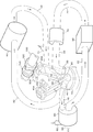
図1には、本実施例の主要部が示されている。同図に示すように、シリンダ10に対して、4つのバルブ20,30,40,50が設けられている。バルブ40とバルブ50の間には、加圧チャンバ60が設けられている。また、バルブ20とバルブ30の間には、外部過給機(ターボチャージャー)80が設けられている。各バルブと作用は、次の通りである。
(1)吸気バルブ20:シリンダ10内に圧縮された空気を吸気する際に開くバルブである。
(2)排気バルブ30:燃焼後のガスをシリンダ10内から排気する際に開くバルブである。
(3)加圧チャンバ送出バルブ40:シリンダ10内で加圧した空気を加圧チャンバ60に送出するためのバルブである。
(4)加圧チャンバ吸入バルブ50:加圧チャンバ60内に滞留した加圧空気を吸入してシリンダ10内に戻すためのバルブである。 FIG. 1 shows the main part of this embodiment. As shown in FIG. 4, four valves 20, 30, 40, and 50 are provided for the cylinder 10. A pressurizing chamber 60 is provided between the valve 40 and the valve 50. An external supercharger (turbocharger) 80 is provided between the valve 20 and the valve 30. Each valve and operation are as follows.
(1) Intake valve 20: This valve opens when the compressed air in thecylinder 10 is taken in.
(2) Exhaust valve 30: This valve is opened when the gas after combustion is exhausted from thecylinder 10.
(3) Pressurized chamber delivery valve 40: A valve for delivering pressurized air in thecylinder 10 to the pressurized chamber 60.
(4) Pressurized chamber suction valve 50: A valve for sucking the pressurized air staying in the pressurizedchamber 60 and returning it to the cylinder 10.
(1)吸気バルブ20:シリンダ10内に圧縮された空気を吸気する際に開くバルブである。
(2)排気バルブ30:燃焼後のガスをシリンダ10内から排気する際に開くバルブである。
(3)加圧チャンバ送出バルブ40:シリンダ10内で加圧した空気を加圧チャンバ60に送出するためのバルブである。
(4)加圧チャンバ吸入バルブ50:加圧チャンバ60内に滞留した加圧空気を吸入してシリンダ10内に戻すためのバルブである。 FIG. 1 shows the main part of this embodiment. As shown in FIG. 4, four
(1) Intake valve 20: This valve opens when the compressed air in the
(2) Exhaust valve 30: This valve is opened when the gas after combustion is exhausted from the
(3) Pressurized chamber delivery valve 40: A valve for delivering pressurized air in the
(4) Pressurized chamber suction valve 50: A valve for sucking the pressurized air staying in the pressurized
図2(A)には、上述したバルブの大きさが示されており、吸気バルブ20は、排気バルブ30よりも口径ないし断面積が大きく、吸気を効率的に行えるようになっている。また、加圧チャンバ送出バルブ40は、加圧チャンバ吸入バルブ50よりも口径ないし断面積が大きく、加圧チャンバ60への空気送出が効率的に行えるようになっている。
FIG. 2 (A) shows the size of the valve described above, and the intake valve 20 has a larger diameter or cross-sectional area than the exhaust valve 30 so that intake can be performed efficiently. Further, the pressurized chamber delivery valve 40 has a larger diameter or cross-sectional area than the pressurized chamber suction valve 50, and can efficiently deliver air to the pressurized chamber 60.
上述した吸気バルブ20には、外部過給機80によって圧縮された空気が、吸気ポート22を介して供給されている。前記外部過給機80と吸気バルブ20の間には、圧縮空気を冷却するための冷却装置90と、流量を調節するためのスロットル機構70が設けられている。排気バルブ30は、燃焼後の残留ガスを排気する排気ポート32を介して、前記外部過給機80に接続されている。前記外部過給機80には、吸気ポート82を介して空気(大気)が吸気され、排気ポート84から排気されるようになっている。過給機としては、各種のものが知られているが、本実施例における外部過給機80は、タービンとコンプレッサを備えており、排気バルブ30から排気された残留ガスによってタービンを回転させ、これによりコンプレッサで吸気ポート82から吸気された空気が圧縮されるようになっている。
一方、加圧チャンバ送出バルブ40は、加圧送出ポート42を介して加圧チャンバ60の空気入口に接続されている。加圧チャンバ60の空気出口は、加圧吸入ポート52を介して加圧チャンバ吸入バルブ50に接続されている。すなわち、加圧チャンバ送出バルブ40から送出されて加圧チャンバ60に導入された加圧空気は、加圧チャンバ吸入バルブ50からシリンダ10内に吸い込まれて戻るようになっている。 The air compressed by theexternal supercharger 80 is supplied to the intake valve 20 described above via the intake port 22. A cooling device 90 for cooling the compressed air and a throttle mechanism 70 for adjusting the flow rate are provided between the external supercharger 80 and the intake valve 20. The exhaust valve 30 is connected to the external supercharger 80 via an exhaust port 32 that exhausts residual gas after combustion. Air (atmosphere) is sucked into the external supercharger 80 through the intake port 82 and exhausted from the exhaust port 84. Various types of superchargers are known, but the external supercharger 80 in this embodiment includes a turbine and a compressor, and rotates the turbine with residual gas exhausted from the exhaust valve 30, As a result, the air taken in from the intake port 82 is compressed by the compressor.
On the other hand, the pressurizedchamber delivery valve 40 is connected to the air inlet of the pressurized chamber 60 via the pressurized delivery port 42. The air outlet of the pressurization chamber 60 is connected to the pressurization chamber suction valve 50 via the pressurization suction port 52. That is, the pressurized air delivered from the pressurized chamber delivery valve 40 and introduced into the pressurized chamber 60 is sucked back into the cylinder 10 from the pressurized chamber suction valve 50.
一方、加圧チャンバ送出バルブ40は、加圧送出ポート42を介して加圧チャンバ60の空気入口に接続されている。加圧チャンバ60の空気出口は、加圧吸入ポート52を介して加圧チャンバ吸入バルブ50に接続されている。すなわち、加圧チャンバ送出バルブ40から送出されて加圧チャンバ60に導入された加圧空気は、加圧チャンバ吸入バルブ50からシリンダ10内に吸い込まれて戻るようになっている。 The air compressed by the
On the other hand, the pressurized
なお、上述したバルブの大きさに対応するように、ポートの大きさも設定されている。すなわち、吸気ポート22は排気ポート32よりも口径ないし断面積が大きく設定されており、加圧送出ポート42は、加圧吸入ポート52よりも口径ないし断面積が大きく設定されている。
Note that the size of the port is also set to correspond to the size of the valve described above. That is, the intake port 22 has a larger diameter or cross-sectional area than the exhaust port 32, and the pressurized delivery port 42 has a larger diameter or cross-sectional area than the pressurized intake port 52.
図2(B)には、上述したスロットル機構70の一例が示されている。同図に示すように、管路72の中央にはスロットルバルブ74が設けられており、中心軸に対して矢印F74方向に回動可能とすることで、管路の開閉が行なわれる。スロットルバルブ74は、公知のように自動車のアクセル(図示せず)の動作に呼応しており、図示の実線の位置は、いわゆるアイドリング状態であり、点線で示す位置がアクセルを踏み切ったフルスロットル状態である。管路72の側面にはバイパス76が設けられており、アイドリング状態でも、このバイパス76を通じて小量の気体流通が確保されている。バイパス76には、アイドル状態における気体流量を調整するアイドル・アジャスト・スクリュー78が設けられている。
FIG. 2 (B) shows an example of the throttle mechanism 70 described above. As shown in the figure, a throttle valve 74 is provided at the center of the pipe line 72, and the pipe line is opened and closed by being rotatable in the direction of arrow F74 with respect to the central axis. The throttle valve 74 responds to the operation of an automobile accelerator (not shown) as is well known, and the position shown by the solid line in the figure is a so-called idling state, and the position shown by the dotted line is a full throttle state where the accelerator is stepped on. It is. A bypass 76 is provided on the side surface of the pipeline 72, and a small amount of gas flow is secured through the bypass 76 even in an idling state. The bypass 76 is provided with an idle adjustment screw 78 for adjusting the gas flow rate in the idle state.
図1に戻って、上述したバルブ20,30,40,50の端部には、ロッカーアーム20A,30A,40A,50Aをそれぞれ介してカム120,130,140,150(120,150のみ図示)が当接しており、それらカムの回転によって、後述する開閉動作が行われるようになっている。これらのバルブ駆動機構としては、各種のものが公知であり、いずれを適用してもよい。前記バルブに囲まれたシリンダ中央には、燃料点火用のプラグ12が設けられている。
Returning to FIG. 1, cams 120, 130, 140, and 150 (only 120 and 150 are shown) are provided at the ends of the above-described valves 20, 30, 40, and 50 through rocker arms 20A, 30A, 40A, and 50A, respectively. Are in contact with each other, and the opening / closing operation described later is performed by the rotation of the cams. Various types of these valve drive mechanisms are known, and any of them may be applied. A fuel ignition plug 12 is provided at the center of the cylinder surrounded by the valve.
更に、前記加圧吸入ポート52の加圧チャンバ吸入バルブ50側には、燃料ポート71が接続されており、燃料ガスが供給されるようになっている。この燃料ガスは、加圧チャンバ60から送り出された空気と混ざり合って、シリンダ10内に供給される。燃料ガスの量は、アクセルの動きに対応して電子的に制御されており、スロットル機構70のスロットルバルブ74の開閉もアクセルの動きに対応している。従って、アクセルの動きに対応して、圧縮空気の量と燃料の量が制御されている。
Further, a fuel port 71 is connected to the pressurization chamber suction valve 50 side of the pressurization suction port 52 so that fuel gas is supplied. This fuel gas is mixed with the air sent out from the pressurizing chamber 60 and supplied into the cylinder 10. The amount of fuel gas is electronically controlled according to the movement of the accelerator, and the opening and closing of the throttle valve 74 of the throttle mechanism 70 also corresponds to the movement of the accelerator. Accordingly, the amount of compressed air and the amount of fuel are controlled in accordance with the movement of the accelerator.
なお、燃料は、前記説明のように、燃料ポート71からシリンダ10内に導入してもよいし、インジェクションノズルによって直接シリンダ10内に噴射するようにしてもよい。ディーゼルの場合は、プラグ12の代わりに燃料のインジェクションノズルを設けるようにする。
Note that the fuel may be introduced into the cylinder 10 from the fuel port 71 as described above, or may be directly injected into the cylinder 10 by an injection nozzle. In the case of diesel, a fuel injection nozzle is provided instead of the plug 12.
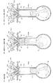
図3及び図4には、本実施例における6サイクルの各行程における主要部の状態が示されている。なお、図3及び図4は、本発明の理解を容易にするために、4つのバルブ20,30,40,50を並列的に示している。シリンダ10内のピストン14がコンロッド16を介してクランクシャフト18に接合している点は、公知の技術と同様である。以下、順次各行程の動作について説明する。
(1)吸気行程:図3(A)に示すように、シリンダ10内のピストン14が、矢印F3Aのように下降し、吸気バルブ20が開いて、外部過給機80で圧縮され、冷却装置90で冷却された後、スロットル機構70で流量が調節された空気がシリンダ10内に吸気される。
(2)加圧チャンバ送出行程:図3(B)に示すように、シリンダ10内のピストン14が、矢印F3Bのように上昇し、加圧チャンバ送出バルブ40が開いて、加圧された空気が加圧チャンバ60に送出される。
(3)加圧チャンバ吸入行程:図3(C)に示すように、シリンダ10内のピストン14が、矢印F3Cのように下降し、加圧チャンバ吸入バルブ50が開く。これにより、加圧チャンバ60内に滞留した加圧空気が燃料ガスと混合してシリンダ10内に再び吸入される。
(4)圧縮行程:図4(D)に示すように、バルブ20,30,40,50の全てが閉じた状態でピストン14が、矢印F3Dのように上昇し、混合ガスがシリンダ10内で圧縮される。
(5)燃焼行程:図4(E)に示すように、プラグ12が点火し、シリンダ10内で圧縮されている混合ガスを燃焼・爆発させる。ピストン14は、矢印F3Eのように下降する。
(6)排気行程:図4(F)に示すように、排気バルブ30が開いた状態でピストン14が、矢印F3Fのように上昇し、シリンダ10内の残留ガスが排気される。残留ガスは、排気ポート32を介して外部過給機80に送られ、該外部過給機80のタービンの回転に利用された後、排気ポート84から排気される。 3 and 4 show the state of the main part in each process of 6 cycles in the present embodiment. 3 and 4 show four valves 20, 30, 40, and 50 in parallel in order to facilitate understanding of the present invention. The point that the piston 14 in the cylinder 10 is joined to the crankshaft 18 via the connecting rod 16 is the same as in the known technique. Hereinafter, the operation of each process will be described sequentially.
(1) Intake stroke: As shown in FIG. 3 (A), thepiston 14 in the cylinder 10 descends as shown by the arrow F3A, the intake valve 20 opens, and is compressed by the external supercharger 80. After being cooled at 90, the air whose flow rate is adjusted by the throttle mechanism 70 is taken into the cylinder 10.
(2) Pressurized chamber delivery process: As shown in FIG. 3 (B), thepiston 14 in the cylinder 10 rises as shown by an arrow F3B, and the pressurized chamber delivery valve 40 opens to provide pressurized air. Is delivered to the pressurized chamber 60.
(3) Pressurization chamber suction stroke: As shown in FIG. 3C, thepiston 14 in the cylinder 10 descends as shown by an arrow F3C, and the pressurization chamber suction valve 50 opens. Thereby, the pressurized air staying in the pressurizing chamber 60 is mixed with the fuel gas and sucked into the cylinder 10 again.
(4) Compression stroke: As shown in FIG. 4 (D), with all of the valves 20, 30, 40, 50 closed, the piston 14 rises as indicated by the arrow F3D, and the mixed gas flows in the cylinder 10. Compressed.
(5) Combustion stroke: As shown in FIG. 4E, theplug 12 is ignited, and the mixed gas compressed in the cylinder 10 is burned and exploded. The piston 14 descends as indicated by an arrow F3E.
(6) Exhaust stroke: As shown in FIG. 4 (F), with theexhaust valve 30 opened, the piston 14 rises as indicated by the arrow F3F, and the residual gas in the cylinder 10 is exhausted. The residual gas is sent to the external supercharger 80 through the exhaust port 32, and is used to rotate the turbine of the external supercharger 80, and then exhausted from the exhaust port 84.
(1)吸気行程:図3(A)に示すように、シリンダ10内のピストン14が、矢印F3Aのように下降し、吸気バルブ20が開いて、外部過給機80で圧縮され、冷却装置90で冷却された後、スロットル機構70で流量が調節された空気がシリンダ10内に吸気される。
(2)加圧チャンバ送出行程:図3(B)に示すように、シリンダ10内のピストン14が、矢印F3Bのように上昇し、加圧チャンバ送出バルブ40が開いて、加圧された空気が加圧チャンバ60に送出される。
(3)加圧チャンバ吸入行程:図3(C)に示すように、シリンダ10内のピストン14が、矢印F3Cのように下降し、加圧チャンバ吸入バルブ50が開く。これにより、加圧チャンバ60内に滞留した加圧空気が燃料ガスと混合してシリンダ10内に再び吸入される。
(4)圧縮行程:図4(D)に示すように、バルブ20,30,40,50の全てが閉じた状態でピストン14が、矢印F3Dのように上昇し、混合ガスがシリンダ10内で圧縮される。
(5)燃焼行程:図4(E)に示すように、プラグ12が点火し、シリンダ10内で圧縮されている混合ガスを燃焼・爆発させる。ピストン14は、矢印F3Eのように下降する。
(6)排気行程:図4(F)に示すように、排気バルブ30が開いた状態でピストン14が、矢印F3Fのように上昇し、シリンダ10内の残留ガスが排気される。残留ガスは、排気ポート32を介して外部過給機80に送られ、該外部過給機80のタービンの回転に利用された後、排気ポート84から排気される。 3 and 4 show the state of the main part in each process of 6 cycles in the present embodiment. 3 and 4 show four
(1) Intake stroke: As shown in FIG. 3 (A), the
(2) Pressurized chamber delivery process: As shown in FIG. 3 (B), the
(3) Pressurization chamber suction stroke: As shown in FIG. 3C, the
(4) Compression stroke: As shown in FIG. 4 (D), with all of the
(5) Combustion stroke: As shown in FIG. 4E, the
(6) Exhaust stroke: As shown in FIG. 4 (F), with the
次に、カム120,130,140,150の動きに着目すると、次の通りとなる。なお、いずれのカムも、図3及び図4に示した6サイクルで1回転する。
(1)カム120:吸気バルブ20を開閉するためのカムで、図3(A)の吸気行程でのみ吸気バルブ20を押して開く。
(2)カム130:排気バルブ30を開閉するためのカムで、図4(C)の排気行程でのみ排気バルブ30を押して開く。
(3)カム140:加圧チャンバ送出バルブ40を開閉するためのカムで、図3(B)の加圧チャンバ送出行程でのみ加圧チャンバ送出バルブ40を押して開く。
(4)カム150:加圧チャンバ吸入バルブ50を開閉するためのカムで、図3(C)の加圧チャンバ吸入行程でのみ加圧チャンバ吸入バルブ50を押して開く。 Next, when attention is paid to the movement of the cams 120, 130, 140, 150, it is as follows. Each cam makes one rotation in the 6 cycles shown in FIGS.
(1) Cam 120: A cam for opening and closing theintake valve 20, and pushes and opens the intake valve 20 only in the intake stroke of FIG.
(2) Cam 130: A cam for opening and closing theexhaust valve 30, and pushes and opens the exhaust valve 30 only in the exhaust stroke of FIG.
(3) Cam 140: A cam for opening and closing the pressurizationchamber delivery valve 40, and pushes and opens the pressurization chamber delivery valve 40 only in the pressurization chamber delivery process of FIG.
(4) Cam 150: A cam for opening and closing the pressurizationchamber suction valve 50. The cam 150 pushes and opens the pressurization chamber suction valve 50 only in the pressurization chamber suction process of FIG.
(1)カム120:吸気バルブ20を開閉するためのカムで、図3(A)の吸気行程でのみ吸気バルブ20を押して開く。
(2)カム130:排気バルブ30を開閉するためのカムで、図4(C)の排気行程でのみ排気バルブ30を押して開く。
(3)カム140:加圧チャンバ送出バルブ40を開閉するためのカムで、図3(B)の加圧チャンバ送出行程でのみ加圧チャンバ送出バルブ40を押して開く。
(4)カム150:加圧チャンバ吸入バルブ50を開閉するためのカムで、図3(C)の加圧チャンバ吸入行程でのみ加圧チャンバ吸入バルブ50を押して開く。 Next, when attention is paid to the movement of the
(1) Cam 120: A cam for opening and closing the
(2) Cam 130: A cam for opening and closing the
(3) Cam 140: A cam for opening and closing the pressurization
(4) Cam 150: A cam for opening and closing the pressurization
図5(A)には、以上の行程の全体が示されている。同図中、下死点はピストン14が最も降下した位置を示し、上死点はピストン14が最も上昇した位置を示す。本実施例によれば、図5(A)の6つの行程が、時計方向に順次繰り返し行なわれる。
Fig. 5 (A) shows the entire process. In the figure, the bottom dead center indicates the position where the piston 14 is lowered most, and the top dead center indicates the position where the piston 14 is raised most. According to the present embodiment, the six steps in FIG. 5A are sequentially repeated in the clockwise direction.
図5(B)には、上述したカム120の一例が示されている。なお、カム130,140,150も形状は同じであるので、以下カム120を代表して説明する。同図(B)はカムシャフト100の方向から見た図であり、同図(C)はカムシャフト100の側面から見た図である。これらの図に示すように、カム山122は、60度の範囲に形成されており、これによって6サイクルに1回の割合で吸気バルブ20を押すようになっている。具体的には、60度の範囲の5度内側を基点として、半径2ミリ(R2)の円弧を描くように立ち上がっており、頂部は半径4ミリ(R4)の円弧を描いている。カム山122の立下りは、立ち上がりと対称となっている。一般的な4サイクルエンジンの場合は、図5(B)に点線で一例を示すようになる。
FIG. 5B shows an example of the cam 120 described above. Since the cams 130, 140, and 150 have the same shape, the cam 120 will be described below as a representative. FIG. 2B is a view seen from the direction of the camshaft 100, and FIG. 2C is a view seen from the side of the camshaft 100. FIG. As shown in these drawings, the cam crest 122 is formed in a range of 60 degrees, thereby pushing the intake valve 20 once every six cycles. Specifically, it rises so as to draw an arc with a radius of 2 millimeters (R2), with the base point at 5 degrees inside the range of 60 degrees, and the top portion draws an arc with a radius of 4 millimeters (R4). The fall of the cam mountain 122 is symmetrical with the rise. In the case of a general 4-cycle engine, an example is shown by a dotted line in FIG.
このようなカム120と、上述した各サイクルとの対応関係を示すと、図5(A)に重ねて示すようになる。すなわち、カム120のカム山122が吸気バルブ20を押すときが空気の吸気行程となる。他のカム130,140,150についても同様である。このように、カム120,130,140,150は、いずれも1回転で6サイクルに対応している。一方、クランクシャフト18は、図3及び図4に示したように、2サイクルで1回転するので、6サイクルでは3回転する。このように、本実施例によれば、カムシャフト100の回転数は、クランクシャフト18の回転数の1/3となる。
The correspondence relationship between such a cam 120 and each of the above-described cycles is shown in an overlapping manner in FIG. That is, the time when the cam crest 122 of the cam 120 pushes the intake valve 20 is the air intake stroke. The same applies to the other cams 130, 140, 150. As described above, the cams 120, 130, 140, and 150 all correspond to 6 cycles in one rotation. On the other hand, as shown in FIGS. 3 and 4, the crankshaft 18 makes one rotation in two cycles, and therefore makes three rotations in six cycles. Thus, according to the present embodiment, the rotational speed of the camshaft 100 is 1/3 of the rotational speed of the crankshaft 18.
更に、カム120,130,140,150のカム山の立ち上がりを遅くするとともに、立下りを早くしているため、図5(A)に示すように、上死点及び下死点の前後数度(図示の例では2度)の間では、各サイクルのバルブ開閉動作が重ならず、オーバーラップが生じない。例えば、図5(B)に示すカム120の例では、上述したように、カム山122が60度から5度ずれた位置から立ち上がっており、これによって、前記オーバーラップが生じないようになっている。なお、図5(A)に示したオーバーラップ回避角度と、図5(B)に示したカム山122の立ち上がり基点角度は、静的特性と動的特性の相違から、必ずしも一致するとは限らない。
Further, since the rise of the cam crest of the cams 120, 130, 140, and 150 is delayed and the fall is accelerated, as shown in FIG. 5 (A), several degrees before and after the top dead center and the bottom dead center. Between (in the illustrated example, 2 degrees), the valve opening and closing operations of each cycle do not overlap and overlap does not occur. For example, in the example of the cam 120 shown in FIG. 5B, as described above, the cam crest 122 rises from a position shifted from 60 degrees by 5 degrees, thereby preventing the overlap from occurring. Yes. Note that the overlap avoidance angle shown in FIG. 5 (A) and the rising base angle of the cam crest 122 shown in FIG. 5 (B) are not necessarily the same due to the difference between the static characteristics and the dynamic characteristics. .
図6には、カム120,130,140,150の角度とカムリフトとの関係が示されている。グラフG6は、本実施例の場合で、上述したように、5度から立ち上がり、30度でピークとなって、55度でリフト量ゼロとなる。グラフG4は、4サイクルの場合のカムリフトの一例を示すもので、0度から立ち上がり、45度でピークとなって、90度でリフト量ゼロとなる。クランクシャフト回転数が同じである場合、6サイクルのカムシャフトの回転は4サイクルの場合よりも遅くなる。このため、本実施例の6サイクルの場合にバルブ20,30,40,50が開く時間は、4サイクルの場合に近づくようになる(図6矢印参照)。
FIG. 6 shows the relationship between the angles of the cams 120, 130, 140, and 150 and the cam lift. The graph G6 is the case of the present embodiment, as described above, rising from 5 degrees, peaking at 30 degrees, and zero lift at 55 degrees. Graph G4 shows an example of the cam lift in the case of 4 cycles, rising from 0 degrees, peaking at 45 degrees, and lift amount being zero at 90 degrees. When the crankshaft rotation speed is the same, the rotation of the camshaft in 6 cycles is slower than in the case of 4 cycles. For this reason, the time for which the valves 20, 30, 40 and 50 are opened in the case of 6 cycles in this embodiment approaches that in the case of 4 cycles (see arrow in FIG. 6).
図7には、クランクシャフト回転数(エンジン回転数)に対するエンジン出力,加圧チャンバ60内の加圧圧力,スロットルバルブ角度の関係の一例が示されている。スロットルバルブ角度のグラフGSに着目すると、アイドリング点での角度がゼロで、定格出力点に行くに従って角度は大きくなっていく。エンジン出力のグラフGEに着目すると、アイドリング点でΔWの出力があり、スロットルバルブ角度が大きくなると、エンジン出力も上昇する。すなわち、スロットルバルブ74を回動して開いていくと、シリンダ10に吸入される圧縮空気量が増大するため、エンジン出力も増大する。
一方、加圧チャンバ圧力は、グラフGCに示すように、アイドリング点では高いものの、スロットルバルブ74を回動していくと一旦低下する。すなわち、低速域では、排気バルブ30から排気される残留ガス量が少なく、外部過給機80による過給がほとんど行われない。しかし、その後、更にスロットルバルブ74を回動して角度が大きくなると、加圧チャンバ圧力は上昇する。すなわち、中高速域では、クランクシャフト回転数の増大に伴って、排気バルブ30から排気された残留ガス量も増えるようになり、外部過給機80による過給が良好に行われるようになる。仮に、外部過給機80を設けない場合、チャンバ圧力は、図7に点線GC´で示すように、アイドリング点で最も高く、スロットルバルブ74の角度が大きくなると低下する。このように、シリンダ10に導入する前に空気を圧縮する外部過給機80を前記加圧チャンバ60と併用することで、中・高速域における加圧チャンバ内の圧力を保持して、馬力ないしトルクの減少を抑制することができる。 FIG. 7 shows an example of the relationship between the engine output, the pressurizing pressure in the pressurizingchamber 60, and the throttle valve angle with respect to the crankshaft rotational speed (engine rotational speed). Focusing on the throttle valve angle graph GS, the angle at the idling point is zero, and the angle increases as the rated output point is reached. Focusing on the engine output graph GE, there is an output of ΔW at the idling point, and the engine output increases as the throttle valve angle increases. That is, when the throttle valve 74 is rotated and opened, the amount of compressed air sucked into the cylinder 10 increases, so that the engine output also increases.
On the other hand, as shown in the graph GC, the pressurization chamber pressure is high at the idling point, but once decreases, thethrottle valve 74 is rotated. That is, in the low speed range, the amount of residual gas exhausted from the exhaust valve 30 is small, and supercharging by the external supercharger 80 is hardly performed. However, after that, when the throttle valve 74 is further rotated to increase the angle, the pressure in the pressurized chamber increases. In other words, in the medium and high speed range, the residual gas amount exhausted from the exhaust valve 30 increases as the crankshaft rotation speed increases, and the supercharging by the external supercharger 80 is performed well. If the external supercharger 80 is not provided, the chamber pressure is the highest at the idling point as shown by the dotted line GC ′ in FIG. 7 and decreases as the angle of the throttle valve 74 increases. Thus, by using the external supercharger 80 that compresses air before being introduced into the cylinder 10 together with the pressurizing chamber 60, the pressure in the pressurizing chamber in the middle / high speed range can be maintained, so A decrease in torque can be suppressed.
一方、加圧チャンバ圧力は、グラフGCに示すように、アイドリング点では高いものの、スロットルバルブ74を回動していくと一旦低下する。すなわち、低速域では、排気バルブ30から排気される残留ガス量が少なく、外部過給機80による過給がほとんど行われない。しかし、その後、更にスロットルバルブ74を回動して角度が大きくなると、加圧チャンバ圧力は上昇する。すなわち、中高速域では、クランクシャフト回転数の増大に伴って、排気バルブ30から排気された残留ガス量も増えるようになり、外部過給機80による過給が良好に行われるようになる。仮に、外部過給機80を設けない場合、チャンバ圧力は、図7に点線GC´で示すように、アイドリング点で最も高く、スロットルバルブ74の角度が大きくなると低下する。このように、シリンダ10に導入する前に空気を圧縮する外部過給機80を前記加圧チャンバ60と併用することで、中・高速域における加圧チャンバ内の圧力を保持して、馬力ないしトルクの減少を抑制することができる。 FIG. 7 shows an example of the relationship between the engine output, the pressurizing pressure in the pressurizing
On the other hand, as shown in the graph GC, the pressurization chamber pressure is high at the idling point, but once decreases, the
次に、スロットルバルブ74が閉じているアイドリング点に着目すると、クランクシャフトは、ΔRの回転数で回転している。このとき、エンジン出力はΔWである。一方、定格出力点に着目すると、スロットルバルブ74が全開となるため、エンジン出力は最大となる。しかし、加圧チャンバ圧力は、加圧チャンバ送出バルブ40と、加圧チャンバ吸入バルブ50の大きさが異なるため、僅かではあるが圧力ΔPが生ずる。
Next, focusing on the idling point where the throttle valve 74 is closed, the crankshaft is rotating at a rotational speed of ΔR. At this time, the engine output is ΔW. On the other hand, paying attention to the rated output point, the throttle valve 74 is fully opened, so that the engine output becomes maximum. However, since the pressurized chamber delivery valve 40 and the pressurized chamber suction valve 50 are different in size, the pressure ΔP is slightly generated.
図8には、多気筒の場合における気筒間のサイクルの関係の一例が示されている。同図の横軸は時間,縦軸は気体の吸入ないし排気量(バルブの開き度合い)を示す。まず、1気筒の場合は、同図(A)に示すように、吸気,加圧チャンバ送出,加圧チャンバ吸入,圧縮,燃焼,排気の6サイクルを繰り返す。2気筒の場合は、一方の気筒は前記(A)の動作を行い、他方の気筒は、例えば同図(B)に示す3サイクル遅れの動作を行なうようにする。3気筒の場合は、1番目の気筒は前記(A)の動作を行い、2番目の気筒は、例えば同図(C)に示す2サイクル遅れの動作を行ない、3番目の気筒は、例えば同図(D)に示す4サイクル遅れの動作を行なうようにする。
FIG. 8 shows an example of a cycle relationship between cylinders in the case of multiple cylinders. In the figure, the horizontal axis represents time, and the vertical axis represents the amount of gas drawn or exhausted (the degree of valve opening). First, in the case of one cylinder, as shown in FIG. 5A, six cycles of intake, pressurized chamber delivery, pressurized chamber suction, compression, combustion, and exhaust are repeated. In the case of two cylinders, one cylinder performs the operation (A), and the other cylinder performs, for example, a three-cycle delayed operation shown in FIG. In the case of three cylinders, the first cylinder performs the operation (A) described above, the second cylinder performs an operation delayed by two cycles as shown in FIG. The operation with a delay of 4 cycles shown in FIG.
以上のように、本実施例によれば、次のような効果がある。
(1)4サイクルエンジンに2サイクルの自己加圧サイクルを加え、吸気行程後に、加圧チャンバ60に対する空気の送出と、加圧チャンバ60からの加圧空気の吸入を行なうこととしたので、高いガス圧力で燃焼が行なわれるようになる。このため、6サイクルでありながら、4サイクルに近いトルクないし馬力が得られる。また、4サイクルと比較して、燃料消費の低減,排出ガスの低減を図ることができる。特に、シリンダ10に導入する前に空気を圧縮する外部過給機80を併用することで、中・高速域における加圧チャンバ内60の圧力を保持して中・高速域の馬力ないしトルクの向上を図ることができる。
(2)1サイクル当りのエンジンの回転時間が4サイクルエンジンに比べて1.5倍に長くなるので、各サイクルにおける効率の低下は30%に抑えられる。また、カムシャフトの回転も、4サイクル内燃機関に比べて1.5倍遅くなるので、期間損失比も低下する。更に、カムシャフト駆動抵抗も少ないので、メカニカルノイズが低減されて低騒音性にも有効であり、現状の4サイクルエンジンと同じ気筒数及び燃焼順序を利用することができるので、生産コストを下げることができる。更に、カムやシャフトなどの部品の消耗率も抑えることができる。
(3)エンジンの回転数が同じ場合、4サイクルの場合と比較して燃焼回数が少なくなるため、排気ガス量が低減される。加えて、電動モータ駆動と結合してハイブリッド方式とすることにより、燃料消費の改善を図るとともに、更に排気ガスが減少し、地球温暖化の抑制など環境負荷の低減を図ることが可能となる。
(4)吸気バルブ20及び吸気ポート22,加圧チャンバ送出バルブ40及び加圧送出ポート42を、排気バルブ30及び排気ポート32,加圧チャンバ吸入バルブ50及び加圧吸入ポート52よりも大きくすることとしたので、空気の吸気及び加圧チャンバ60への送出が十分に行われる。このため、燃焼後の残留ガスがあっても吸気した空気が十分に混ざるようになり、これを加圧して再度燃焼させることで、燃焼効率が向上し、窒素酸化物や二酸化炭素の発生を抑制することができる。
(5)カムによるバルブ開閉動作にオーバーラップをなくしているために、未燃焼ガスを加圧チャンバ60に送って再度燃焼を行なうことができる。
(6)シリンダ10からの排気を、外部過給機80に送り、そのタービンの回転に利用することとしたので、熱効率が高く、燃費消費率の低減を図ることができる。 As described above, according to this embodiment, there are the following effects.
(1) A two-cycle self-pressurization cycle is added to a four-cycle engine, and after the intake stroke, air is sent to thepressurization chamber 60 and pressurized air is sucked from the pressurization chamber 60. Combustion is performed at the gas pressure. For this reason, although it is 6 cycles, the torque thru | or horsepower close | similar to 4 cycles are obtained. In addition, compared with four cycles, fuel consumption and exhaust gas can be reduced. In particular, by using an external supercharger 80 that compresses air before it is introduced into the cylinder 10, the pressure in the pressurizing chamber 60 in the middle / high speed range is maintained and the horsepower or torque in the middle / high speed range is improved. Can be achieved.
(2) Since the engine rotation time per cycle is 1.5 times longer than that of the 4-cycle engine, the efficiency reduction in each cycle is suppressed to 30%. Further, since the rotation of the camshaft is also 1.5 times slower than the 4-cycle internal combustion engine, the period loss ratio is also reduced. In addition, since the camshaft drive resistance is small, mechanical noise is reduced and it is effective for low noise, and the same number of cylinders and combustion order as the current four-cycle engine can be used, thus reducing the production cost. Can do. Furthermore, the wear rate of parts such as cams and shafts can be suppressed.
(3) When the engine speed is the same, the number of combustions is reduced as compared with the case of four cycles, so the amount of exhaust gas is reduced. In addition, by combining with the electric motor drive and adopting a hybrid system, it is possible to improve fuel consumption, further reduce exhaust gas, and reduce environmental burdens such as suppression of global warming.
(4) Theintake valve 20 and the intake port 22, the pressurized chamber delivery valve 40 and the pressurized delivery port 42 are made larger than the exhaust valve 30 and the exhaust port 32, the pressurized chamber intake valve 50 and the pressurized intake port 52. Therefore, the intake of air and the delivery to the pressurized chamber 60 are sufficiently performed. For this reason, even if there is residual gas after combustion, the intake air will be sufficiently mixed, and this will be pressurized and burned again, improving combustion efficiency and suppressing the generation of nitrogen oxides and carbon dioxide can do.
(5) Since there is no overlap in the valve opening and closing operation by the cam, unburned gas can be sent to thepressurized chamber 60 and combustion can be performed again.
(6) Since the exhaust from thecylinder 10 is sent to the external supercharger 80 and used for the rotation of the turbine, the heat efficiency is high and the fuel consumption rate can be reduced.
(1)4サイクルエンジンに2サイクルの自己加圧サイクルを加え、吸気行程後に、加圧チャンバ60に対する空気の送出と、加圧チャンバ60からの加圧空気の吸入を行なうこととしたので、高いガス圧力で燃焼が行なわれるようになる。このため、6サイクルでありながら、4サイクルに近いトルクないし馬力が得られる。また、4サイクルと比較して、燃料消費の低減,排出ガスの低減を図ることができる。特に、シリンダ10に導入する前に空気を圧縮する外部過給機80を併用することで、中・高速域における加圧チャンバ内60の圧力を保持して中・高速域の馬力ないしトルクの向上を図ることができる。
(2)1サイクル当りのエンジンの回転時間が4サイクルエンジンに比べて1.5倍に長くなるので、各サイクルにおける効率の低下は30%に抑えられる。また、カムシャフトの回転も、4サイクル内燃機関に比べて1.5倍遅くなるので、期間損失比も低下する。更に、カムシャフト駆動抵抗も少ないので、メカニカルノイズが低減されて低騒音性にも有効であり、現状の4サイクルエンジンと同じ気筒数及び燃焼順序を利用することができるので、生産コストを下げることができる。更に、カムやシャフトなどの部品の消耗率も抑えることができる。
(3)エンジンの回転数が同じ場合、4サイクルの場合と比較して燃焼回数が少なくなるため、排気ガス量が低減される。加えて、電動モータ駆動と結合してハイブリッド方式とすることにより、燃料消費の改善を図るとともに、更に排気ガスが減少し、地球温暖化の抑制など環境負荷の低減を図ることが可能となる。
(4)吸気バルブ20及び吸気ポート22,加圧チャンバ送出バルブ40及び加圧送出ポート42を、排気バルブ30及び排気ポート32,加圧チャンバ吸入バルブ50及び加圧吸入ポート52よりも大きくすることとしたので、空気の吸気及び加圧チャンバ60への送出が十分に行われる。このため、燃焼後の残留ガスがあっても吸気した空気が十分に混ざるようになり、これを加圧して再度燃焼させることで、燃焼効率が向上し、窒素酸化物や二酸化炭素の発生を抑制することができる。
(5)カムによるバルブ開閉動作にオーバーラップをなくしているために、未燃焼ガスを加圧チャンバ60に送って再度燃焼を行なうことができる。
(6)シリンダ10からの排気を、外部過給機80に送り、そのタービンの回転に利用することとしたので、熱効率が高く、燃費消費率の低減を図ることができる。 As described above, according to this embodiment, there are the following effects.
(1) A two-cycle self-pressurization cycle is added to a four-cycle engine, and after the intake stroke, air is sent to the
(2) Since the engine rotation time per cycle is 1.5 times longer than that of the 4-cycle engine, the efficiency reduction in each cycle is suppressed to 30%. Further, since the rotation of the camshaft is also 1.5 times slower than the 4-cycle internal combustion engine, the period loss ratio is also reduced. In addition, since the camshaft drive resistance is small, mechanical noise is reduced and it is effective for low noise, and the same number of cylinders and combustion order as the current four-cycle engine can be used, thus reducing the production cost. Can do. Furthermore, the wear rate of parts such as cams and shafts can be suppressed.
(3) When the engine speed is the same, the number of combustions is reduced as compared with the case of four cycles, so the amount of exhaust gas is reduced. In addition, by combining with the electric motor drive and adopting a hybrid system, it is possible to improve fuel consumption, further reduce exhaust gas, and reduce environmental burdens such as suppression of global warming.
(4) The
(5) Since there is no overlap in the valve opening and closing operation by the cam, unburned gas can be sent to the
(6) Since the exhaust from the
なお、本発明は、上述した実施例に限定されるものではなく、本発明の要旨を逸脱しない範囲内において種々変更を加え得ることができる。例えば、以下のものも含まれる。
(1)前記実施例では、シリンダ1つの場合(1気筒)を主として説明したが、もちろん公知の多気筒構成とすることでクランクシャフトの回転を滑らかにすることを妨げるものではない。
(2)加圧チャンバ60及び外部過給機80は、各シリンダ毎に設けてもよいが、加圧チャンバへの空気の送出と吸入は2サイクルで行なわれるので、3気筒に対して一つの加圧チャンバ60及び外部過給機80を設け、順次使用することで、装置構成を簡略化することができる。
(3)バルブ開閉機構,ピストン機構など、公知の技術を適用することを妨げるものではない。
(4)前記実施例では、シリンダ10からの排気を外部過給機80で利用することとしたが、これも一例であり、排気ポート32から直接排気するようにしてもよい。
(5)本発明は、主としてガソリンエンジンに好適であるが、ディーゼル,LPG,エタノールなど各種の燃料に適用することができる。また、自動車に限らず、船舶,発電機など、各種の用途に適用してよい。
(6)前記実施例では、外部過給機80として、排気ガスのエネルギーを利用して空気を圧縮しているが、エンジンの出力軸からベルト等を介して取り出した動力によってコンプレッサを駆動し、空気を圧縮する方式の過給機(スーパーターボチャージャー)を用いてもよい。この方法によれば、低速側においても、良好な馬力ないしトルクを得ることができる。 In addition, this invention is not limited to the Example mentioned above, A various change can be added in the range which does not deviate from the summary of this invention. For example, the following are also included.
(1) In the above embodiment, the case of one cylinder (one cylinder) has been mainly described. Of course, a known multi-cylinder configuration does not prevent smooth rotation of the crankshaft.
(2) The pressurizingchamber 60 and the external supercharger 80 may be provided for each cylinder. However, since air is supplied to and sucked into the pressurizing chamber in two cycles, one press is provided for three cylinders. By providing the pressurizing chamber 60 and the external supercharger 80 and using them sequentially, the apparatus configuration can be simplified.
(3) It does not prevent application of known techniques such as a valve opening / closing mechanism and a piston mechanism.
(4) In the above embodiment, the exhaust from thecylinder 10 is used by the external supercharger 80, but this is also an example, and the exhaust may be directly exhausted from the exhaust port 32.
(5) The present invention is mainly suitable for a gasoline engine, but can be applied to various fuels such as diesel, LPG, and ethanol. Moreover, you may apply not only to a motor vehicle but to various uses, such as a ship and a generator.
(6) In the above embodiment, as theexternal supercharger 80, air is compressed using the energy of the exhaust gas, but the compressor is driven by the power extracted from the engine output shaft through a belt or the like, A supercharger (super turbocharger) that compresses air may be used. According to this method, good horsepower or torque can be obtained even on the low speed side.
(1)前記実施例では、シリンダ1つの場合(1気筒)を主として説明したが、もちろん公知の多気筒構成とすることでクランクシャフトの回転を滑らかにすることを妨げるものではない。
(2)加圧チャンバ60及び外部過給機80は、各シリンダ毎に設けてもよいが、加圧チャンバへの空気の送出と吸入は2サイクルで行なわれるので、3気筒に対して一つの加圧チャンバ60及び外部過給機80を設け、順次使用することで、装置構成を簡略化することができる。
(3)バルブ開閉機構,ピストン機構など、公知の技術を適用することを妨げるものではない。
(4)前記実施例では、シリンダ10からの排気を外部過給機80で利用することとしたが、これも一例であり、排気ポート32から直接排気するようにしてもよい。
(5)本発明は、主としてガソリンエンジンに好適であるが、ディーゼル,LPG,エタノールなど各種の燃料に適用することができる。また、自動車に限らず、船舶,発電機など、各種の用途に適用してよい。
(6)前記実施例では、外部過給機80として、排気ガスのエネルギーを利用して空気を圧縮しているが、エンジンの出力軸からベルト等を介して取り出した動力によってコンプレッサを駆動し、空気を圧縮する方式の過給機(スーパーターボチャージャー)を用いてもよい。この方法によれば、低速側においても、良好な馬力ないしトルクを得ることができる。 In addition, this invention is not limited to the Example mentioned above, A various change can be added in the range which does not deviate from the summary of this invention. For example, the following are also included.
(1) In the above embodiment, the case of one cylinder (one cylinder) has been mainly described. Of course, a known multi-cylinder configuration does not prevent smooth rotation of the crankshaft.
(2) The pressurizing
(3) It does not prevent application of known techniques such as a valve opening / closing mechanism and a piston mechanism.
(4) In the above embodiment, the exhaust from the
(5) The present invention is mainly suitable for a gasoline engine, but can be applied to various fuels such as diesel, LPG, and ethanol. Moreover, you may apply not only to a motor vehicle but to various uses, such as a ship and a generator.
(6) In the above embodiment, as the
本発明によれば、出力が多少低下するものの、燃料消費が低減されるとともに、環境負荷も抑制されるので、ハイブリッド方式の内燃機関に好適である。また、シリンダに導入する前に空気を圧縮する外部過給機を併用することで、馬力ないしトルクの向上を図ることができる。
According to the present invention, although the output is somewhat reduced, the fuel consumption is reduced and the environmental load is also suppressed, which is suitable for a hybrid internal combustion engine. Further, by using an external supercharger that compresses air before being introduced into the cylinder, it is possible to improve horsepower or torque.
10:シリンダ
12:プラグ
14:ピストン
16:コンロッド
18:クランクシャフト
20:吸気バルブ
20A,30A,40A,50A:ロッカーアーム
22:吸気ポート
30:排気バルブ
32:排気ポート
40:加圧チャンバ送出バルブ
42:加圧送出ポート
50:加圧チャンバ吸入バルブ
52:加圧吸入ポート
60:加圧チャンバ
70:スロットル機構
71:燃料ポート
72:管路
74:スロットルバルブ
76:バイパス
78:アイドル・アジャスト・スクリュー
80:外部過給機
82:吸気ポート
84:排気ポート
90:冷却装置
100:カムシャフト
120,130,140,150:カム
122:カム山 10: cylinder 12: plug 14: piston 16: connecting rod 18: crankshaft 20: intake valve 20A, 30A, 40A, 50A: rocker arm 22: intake port 30: exhaust valve 32: exhaust port 40: pressurized chamber delivery valve 42 : Pressurization delivery port 50: Pressurization chamber suction valve 52: Pressurization suction port 60: Pressurization chamber 70: Throttle mechanism 71: Fuel port 72: Pipe line 74: Throttle valve 76: Bypass 78: Idle adjustment screw 80 : External turbocharger 82: Intake port 84: Exhaust port 90: Cooling device 100: Camshaft 120, 130, 140, 150: Cam 122: Cam mountain
12:プラグ
14:ピストン
16:コンロッド
18:クランクシャフト
20:吸気バルブ
20A,30A,40A,50A:ロッカーアーム
22:吸気ポート
30:排気バルブ
32:排気ポート
40:加圧チャンバ送出バルブ
42:加圧送出ポート
50:加圧チャンバ吸入バルブ
52:加圧吸入ポート
60:加圧チャンバ
70:スロットル機構
71:燃料ポート
72:管路
74:スロットルバルブ
76:バイパス
78:アイドル・アジャスト・スクリュー
80:外部過給機
82:吸気ポート
84:排気ポート
90:冷却装置
100:カムシャフト
120,130,140,150:カム
122:カム山 10: cylinder 12: plug 14: piston 16: connecting rod 18: crankshaft 20:
Claims (7)
- シリンダ内でピストンが往復運動する際にバルブの開閉を行う内燃機関であって、
加圧空気を一時的に滞留するための加圧チャンバが設けられており、
前記シリンダには、吸気バルブ,加圧チャンバ送出バルブ,加圧チャンバ吸入バルブ,排気バルブが設けられており、
前記シリンダ内に吸入する燃料を含まない空気を圧縮する外部過給機が設けられており、
前記外部過給機と前記吸気バルブとの間に、前記外部過給機から吸入する空気の量を調整するスロットル機構が設けられており、
前記外部過給機と前記スロットル機構の間に、空気を冷却するためのクーラーが設けられており、
前記スロットル機構は、吸入側が前記クーラー側に接続されており、排気側が前記吸気バルブ側に接続されている管路と、車両のアクセルの動作に呼応して前記管路を開閉することで、前記外部過給機側から吸入して前記吸気バルブ側に排気する空気の量を調整するスロットルバルブとを備えており、
ピストンが下降するときに、前記吸気バルブを開いて、燃料を含まない圧縮された空気を前記シリンダ内に吸気する吸気行程,
ピストンが上昇するときに、前記吸気行程によって前記シリンダ内に吸気された空気を加圧し、前記加圧チャンバ送出バルブを開いて、前記加圧チャンバに送出する加圧チャンバ送出行程,
ピストンが下降するときに、前記加圧チャンバ送出行程によって加圧チャンバ内に滞留した空気を、前記吸気バルブを閉じた状態で前記加圧チャンバ吸入バルブを開いて、前記空気を送出したシリンダ内に吸入して戻すとともに、同時に燃料をシリンダ内に吸入する加圧チャンバ吸入行程,
ピストンが上昇するときに、前記加圧チャンバ吸入行程によって前記シリンダ内に吸入された空気と燃料の混合ガスを圧縮する圧縮行程,
この圧縮行程によって圧縮された混合ガスを燃焼・爆発させ、ピストンを下降させる燃焼行程,
ピストンが上昇するときに、前記燃焼行程による燃焼後の残留ガスを、前記排気バルブを開いて、前記シリンダ内から排気する排気行程,
を繰り返し行うことを特徴とする内燃機関。 An internal combustion engine that opens and closes a valve when a piston reciprocates in a cylinder,
A pressurized chamber is provided for temporarily retaining pressurized air;
The cylinder is provided with an intake valve, a pressurized chamber delivery valve, a pressurized chamber intake valve, and an exhaust valve,
An external supercharger for compressing air that does not contain fuel to be sucked into the cylinder;
Between the external supercharger and the intake valve, a throttle mechanism for adjusting the amount of air sucked from the external supercharger is provided,
A cooler for cooling the air is provided between the external supercharger and the throttle mechanism,
The throttle mechanism has an intake side connected to the cooler side, an exhaust side connected to the intake valve side, and opens and closes the pipeline in response to an accelerator operation of the vehicle. A throttle valve that adjusts the amount of air sucked from the external supercharger side and exhausted to the intake valve side;
An intake stroke for opening the intake valve and sucking compressed air containing no fuel into the cylinder when the piston descends;
A pressurization chamber delivery stroke for pressurizing air sucked into the cylinder by the intake stroke and opening the pressurization chamber delivery valve to deliver the piston to the pressurization chamber when the piston moves up;
When the piston descends, the air staying in the pressurization chamber by the pressurization chamber delivery stroke is opened in the cylinder that has sent out the air by opening the pressurization chamber suction valve with the intake valve closed. A suction chamber suction stroke for sucking back and simultaneously sucking fuel into the cylinder;
A compression stroke for compressing a mixed gas of air and fuel sucked into the cylinder by the pressurized chamber suction stroke when the piston moves up;
Combustion stroke that burns and explodes the gas mixture compressed by this compression stroke and lowers the piston,
An exhaust stroke in which, when the piston is raised, residual gas after combustion in the combustion stroke is exhausted from the cylinder by opening the exhaust valve;
An internal combustion engine characterized by repeating the above. - 前記排気工程によって前記シリンダ内から排気した残留ガスを、前記外部過給機の駆動に利用することを特徴する請求項1記載の内燃機関。 The internal combustion engine according to claim 1, wherein residual gas exhausted from the cylinder by the exhaust process is used for driving the external supercharger.
- 前記内燃機関の出力によって、前記外部過給機を駆動することを特徴とする請求項1記載の内燃機関。 The internal combustion engine according to claim 1, wherein the external supercharger is driven by the output of the internal combustion engine.
- 前記吸気バルブ及び加圧チャンバ送出バルブの口径を、前記排気バルブ及び加圧チャンバ吸入バルブの口径より大きくなるように設定したことを特徴とする請求項1記載の内燃機関。 The internal combustion engine according to claim 1, wherein the intake valve and the pressurization chamber delivery valve are set to be larger in diameter than the exhaust valve and the pressurization chamber intake valve.
- カムによって前記各行程における各バルブの開閉を行う際に、前記各行程の動作がオーバーラップしないように、前記カムの形状を規定したことを特徴とする請求項1記載の内燃機関。 2. The internal combustion engine according to claim 1, wherein the shape of the cam is defined so that the operations of the strokes do not overlap when the valves are opened and closed by the cam.
- 前記シリンダを複数設けた多気筒構成とするとともに、前記加圧チャンバ及び外部過給機を複数のシリンダ間で共用することを特徴とする請求項1記載の内燃機関。 2. An internal combustion engine according to claim 1, wherein a plurality of cylinders are provided, and the pressurization chamber and the external supercharger are shared among the plurality of cylinders.
- 請求項1~5のいずれかに記載の内燃機関と電気モータとを併用したことを特徴とするハイブリッド方式の駆動システム。 A hybrid drive system characterized by using the internal combustion engine according to any one of claims 1 to 5 and an electric motor in combination.
Priority Applications (1)
| Application Number | Priority Date | Filing Date | Title |
|---|---|---|---|
| PCT/JP2013/061679 WO2014171017A1 (en) | 2013-04-19 | 2013-04-19 | Internal combustion engine and drive system |
Applications Claiming Priority (1)
| Application Number | Priority Date | Filing Date | Title |
|---|---|---|---|
| PCT/JP2013/061679 WO2014171017A1 (en) | 2013-04-19 | 2013-04-19 | Internal combustion engine and drive system |
Publications (1)
| Publication Number | Publication Date |
|---|---|
| WO2014171017A1 true WO2014171017A1 (en) | 2014-10-23 |
Family
ID=51730985
Family Applications (1)
| Application Number | Title | Priority Date | Filing Date |
|---|---|---|---|
| PCT/JP2013/061679 WO2014171017A1 (en) | 2013-04-19 | 2013-04-19 | Internal combustion engine and drive system |
Country Status (1)
| Country | Link |
|---|---|
| WO (1) | WO2014171017A1 (en) |
Citations (3)
| Publication number | Priority date | Publication date | Assignee | Title |
|---|---|---|---|---|
| JPH02119635A (en) * | 1988-10-28 | 1990-05-07 | Mazda Motor Corp | Six-cycle engine |
| JP2005155603A (en) * | 2003-11-04 | 2005-06-16 | Denso Corp | Internal combustion engine |
| JP2010031705A (en) * | 2008-07-26 | 2010-02-12 | Shigeru Sato | Internal combustion engine and drive system |
-
2013
- 2013-04-19 WO PCT/JP2013/061679 patent/WO2014171017A1/en active Application Filing
Patent Citations (3)
| Publication number | Priority date | Publication date | Assignee | Title |
|---|---|---|---|---|
| JPH02119635A (en) * | 1988-10-28 | 1990-05-07 | Mazda Motor Corp | Six-cycle engine |
| JP2005155603A (en) * | 2003-11-04 | 2005-06-16 | Denso Corp | Internal combustion engine |
| JP2010031705A (en) * | 2008-07-26 | 2010-02-12 | Shigeru Sato | Internal combustion engine and drive system |
Similar Documents
| Publication | Publication Date | Title |
|---|---|---|
| US8534261B2 (en) | Four-cycle engine | |
| US9951679B2 (en) | Reciprocating internal combustion engine | |
| US8613269B2 (en) | Internal combustion engine with direct air injection | |
| JP4980314B2 (en) | Internal combustion engine and drive system | |
| KR20080042149A (en) | A two-stroke engine with variable compression | |
| US20060048981A1 (en) | High output and efficiency internal combustion engine | |
| JP5608175B2 (en) | Internal combustion engine with independent gas supply system without compression stroke | |
| US9470139B2 (en) | Supercharged engine design | |
| US20130298552A1 (en) | Systems and methods for series-sequential turbocharging | |
| JP6541825B2 (en) | Camshaft and internal combustion engine | |
| WO2014171017A1 (en) | Internal combustion engine and drive system | |
| US8443773B2 (en) | Methods for controlling valves of an internal combustion engine, devices for controlling the valves, and engines employing the methods | |
| WO2015140868A1 (en) | Internal-combustion engine and drive system | |
| Nuccio et al. | Development through simulation of a turbocharged 2-stroke GDI engine focused on a range-extender application | |
| WO2008055329A1 (en) | Internal-combustion engine and the vehicle containing such engine | |
| US9476349B1 (en) | Three and two half stroke freeboost internal combustion engine | |
| JP6359146B1 (en) | Internal combustion engine and drive system | |
| JP6177928B2 (en) | Internal combustion engine and drive system | |
| JP6113985B2 (en) | Internal combustion engine and drive system | |
| US11808231B2 (en) | Negative pressure operating method | |
| JP5002721B1 (en) | Operating gas generator | |
| Vasile et al. | Rapid start of hybrid pneumatic engines | |
| MISHRA | FOUR STROKE ENGINE | |
| US20160290192A1 (en) | Two-stroke compression ignition engine |
Legal Events
| Date | Code | Title | Description |
|---|---|---|---|
| 121 | Ep: the epo has been informed by wipo that ep was designated in this application |
Ref document number: 13882337 Country of ref document: EP Kind code of ref document: A1 |
|
| NENP | Non-entry into the national phase |
Ref country code: DE |
|
| 122 | Ep: pct application non-entry in european phase |
Ref document number: 13882337 Country of ref document: EP Kind code of ref document: A1 |
|
| NENP | Non-entry into the national phase |
Ref country code: JP |