WO2014163209A1 - 画像復号装置 - Google Patents
画像復号装置 Download PDFInfo
- Publication number
- WO2014163209A1 WO2014163209A1 PCT/JP2014/060121 JP2014060121W WO2014163209A1 WO 2014163209 A1 WO2014163209 A1 WO 2014163209A1 JP 2014060121 W JP2014060121 W JP 2014060121W WO 2014163209 A1 WO2014163209 A1 WO 2014163209A1
- Authority
- WO
- WIPO (PCT)
- Prior art keywords
- image
- unit
- prediction
- decoding
- ctb
- Prior art date
- Legal status (The legal status is an assumption and is not a legal conclusion. Google has not performed a legal analysis and makes no representation as to the accuracy of the status listed.)
- Ceased
Links
Images



Classifications
-
- H—ELECTRICITY
- H04—ELECTRIC COMMUNICATION TECHNIQUE
- H04N—PICTORIAL COMMUNICATION, e.g. TELEVISION
- H04N19/00—Methods or arrangements for coding, decoding, compressing or decompressing digital video signals
- H04N19/30—Methods or arrangements for coding, decoding, compressing or decompressing digital video signals using hierarchical techniques, e.g. scalability
-
- H—ELECTRICITY
- H04—ELECTRIC COMMUNICATION TECHNIQUE
- H04N—PICTORIAL COMMUNICATION, e.g. TELEVISION
- H04N19/00—Methods or arrangements for coding, decoding, compressing or decompressing digital video signals
- H04N19/50—Methods or arrangements for coding, decoding, compressing or decompressing digital video signals using predictive coding
- H04N19/503—Methods or arrangements for coding, decoding, compressing or decompressing digital video signals using predictive coding involving temporal prediction
- H04N19/51—Motion estimation or motion compensation
- H04N19/577—Motion compensation with bidirectional frame interpolation, i.e. using B-pictures
-
- H—ELECTRICITY
- H04—ELECTRIC COMMUNICATION TECHNIQUE
- H04N—PICTORIAL COMMUNICATION, e.g. TELEVISION
- H04N19/00—Methods or arrangements for coding, decoding, compressing or decompressing digital video signals
- H04N19/10—Methods or arrangements for coding, decoding, compressing or decompressing digital video signals using adaptive coding
- H04N19/169—Methods or arrangements for coding, decoding, compressing or decompressing digital video signals using adaptive coding characterised by the coding unit, i.e. the structural portion or semantic portion of the video signal being the object or the subject of the adaptive coding
- H04N19/17—Methods or arrangements for coding, decoding, compressing or decompressing digital video signals using adaptive coding characterised by the coding unit, i.e. the structural portion or semantic portion of the video signal being the object or the subject of the adaptive coding the unit being an image region, e.g. an object
- H04N19/172—Methods or arrangements for coding, decoding, compressing or decompressing digital video signals using adaptive coding characterised by the coding unit, i.e. the structural portion or semantic portion of the video signal being the object or the subject of the adaptive coding the unit being an image region, e.g. an object the region being a picture, frame or field
-
- H—ELECTRICITY
- H04—ELECTRIC COMMUNICATION TECHNIQUE
- H04N—PICTORIAL COMMUNICATION, e.g. TELEVISION
- H04N19/00—Methods or arrangements for coding, decoding, compressing or decompressing digital video signals
- H04N19/10—Methods or arrangements for coding, decoding, compressing or decompressing digital video signals using adaptive coding
- H04N19/169—Methods or arrangements for coding, decoding, compressing or decompressing digital video signals using adaptive coding characterised by the coding unit, i.e. the structural portion or semantic portion of the video signal being the object or the subject of the adaptive coding
- H04N19/187—Methods or arrangements for coding, decoding, compressing or decompressing digital video signals using adaptive coding characterised by the coding unit, i.e. the structural portion or semantic portion of the video signal being the object or the subject of the adaptive coding the unit being a scalable video layer
-
- H—ELECTRICITY
- H04—ELECTRIC COMMUNICATION TECHNIQUE
- H04N—PICTORIAL COMMUNICATION, e.g. TELEVISION
- H04N19/00—Methods or arrangements for coding, decoding, compressing or decompressing digital video signals
- H04N19/44—Decoders specially adapted therefor, e.g. video decoders which are asymmetric with respect to the encoder
-
- H—ELECTRICITY
- H04—ELECTRIC COMMUNICATION TECHNIQUE
- H04N—PICTORIAL COMMUNICATION, e.g. TELEVISION
- H04N19/00—Methods or arrangements for coding, decoding, compressing or decompressing digital video signals
- H04N19/50—Methods or arrangements for coding, decoding, compressing or decompressing digital video signals using predictive coding
-
- H—ELECTRICITY
- H04—ELECTRIC COMMUNICATION TECHNIQUE
- H04N—PICTORIAL COMMUNICATION, e.g. TELEVISION
- H04N19/00—Methods or arrangements for coding, decoding, compressing or decompressing digital video signals
- H04N19/90—Methods or arrangements for coding, decoding, compressing or decompressing digital video signals using coding techniques not provided for in groups H04N19/10-H04N19/85, e.g. fractals
- H04N19/91—Entropy coding, e.g. variable length coding [VLC] or arithmetic coding
-
- H—ELECTRICITY
- H04—ELECTRIC COMMUNICATION TECHNIQUE
- H04N—PICTORIAL COMMUNICATION, e.g. TELEVISION
- H04N19/00—Methods or arrangements for coding, decoding, compressing or decompressing digital video signals
- H04N19/42—Methods or arrangements for coding, decoding, compressing or decompressing digital video signals characterised by implementation details or hardware specially adapted for video compression or decompression, e.g. dedicated software implementation
- H04N19/436—Methods or arrangements for coding, decoding, compressing or decompressing digital video signals characterised by implementation details or hardware specially adapted for video compression or decompression, e.g. dedicated software implementation using parallelised computational arrangements
-
- H—ELECTRICITY
- H04—ELECTRIC COMMUNICATION TECHNIQUE
- H04N—PICTORIAL COMMUNICATION, e.g. TELEVISION
- H04N19/00—Methods or arrangements for coding, decoding, compressing or decompressing digital video signals
- H04N19/80—Details of filtering operations specially adapted for video compression, e.g. for pixel interpolation
- H04N19/82—Details of filtering operations specially adapted for video compression, e.g. for pixel interpolation involving filtering within a prediction loop
Definitions
- the present invention relates to an image decoding device, an image encoding device, and a data structure.
- a moving picture coding method composed of a plurality of layers is generally called scalable coding or hierarchical coding.
- scalable coding high coding efficiency is realized by performing prediction between layers.
- a reference layer without performing prediction between layers is called a base layer, and other layers are called enhancement layers.
- Scalable encoding in the case where a layer is composed of viewpoint images is referred to as view scalable encoding.
- the base layer is also called a base view
- the enhancement layer is also called a non-base view.
- scalable coding when a layer is composed of a texture layer (image layer) and a depth layer (distance image layer) is called three-dimensional scalable coding.
- Non-patent Document 1 a technique that transmits the existence of a restriction for parallel encoding and the restriction range (non-referenceable range) as a part of encoded data (parallel decoding information) is known.
- Non-Patent Document 1 there is a problem that the non-referenceable range changes when the CTB size changes because the non-referenceable range is determined in units of CTBs that are encoded block units.
- the encoding apparatus needs to limit the range of the disparity vector to a range that does not refer to the non-referenceable range, but there is a problem that the range of the disparity vector is unclear. . Also, since only the case where the restriction in the vertical direction and the restriction in the horizontal direction are simultaneously performed is defined, it is impossible to define the non-referenceable range only in the vertical direction.
- ultra-low delay decoding can be performed to decode the target view faster, but the reference range is limited on the assumption that the target view is loop-filtered. Therefore, there is a problem that such ultra-low delay decoding is impossible.
- the present invention has been made to solve the above-described problems, and one aspect of the present invention is an image decoding apparatus for decoding a plurality of layer images, wherein the first layer image is decoded at the time of decoding the first layer image.
- An entropy decoding unit that defines a non-referenceable range of the second layer image when referring to a second layer image different from the second layer image, and the non-referenceable range decoded by the entropy decoding unit is vertical
- An image decoding device defined as being based only on a direction offset.
- an entropy decoding unit that defines a non-referenceable range of the second layer image, wherein the entropy decoding unit is based on the non-referenceable range defined based only on the vertical direction or on offsets in the vertical and horizontal directions
- An image decoding apparatus wherein the reference-definable range is defined.
- the non-referenceable range transmitted by the parallel decoding information depends only on the encoding parameter of the target view, there is an effect that it is easy to derive the non-referenceable range. Also, by encoding the offset corresponding to the presence or absence of the loop filter in the target view as the offset information of the parallel decoding information, there is an effect of enabling ultra-low delay decoding.
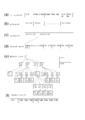
- FIG. 1 is a schematic diagram illustrating a configuration of an image transmission system according to an embodiment of the present invention. It is a figure which shows the hierarchical structure of the data of the encoding stream which concerns on this embodiment. It is the schematic which shows the structure of the coding data of the parallel decoding information decoded by the SEI decoding part which concerns on this embodiment. It is a conceptual diagram which shows the 1st non-referenceable range, 2nd non-referenceable range, and non-referenceable range which concern on this embodiment. It is a conceptual diagram which shows the example of a reference picture. It is the schematic which shows the structure of the image decoding apparatus which concerns on this embodiment. It is a conceptual diagram of the parallel decoding operation
- FIG. 1 is a schematic diagram showing a configuration of an image transmission system 1 according to the present embodiment.
- the image transmission system 1 is a system that transmits a code obtained by encoding a plurality of layer images and displays an image obtained by decoding the transmitted code.
- the image transmission system 1 includes an image encoding device 11, a network 21, an image decoding device 31, and an image display device 41.
- the signal T indicating a plurality of layer images (also referred to as texture images) is input to the image encoding device 11.
- a layer image is an image that is viewed or photographed at a certain resolution and a certain viewpoint.
- each of the plurality of layer images is referred to as a viewpoint image.
- the viewpoint corresponds to the position or observation point of the photographing apparatus.
- the plurality of viewpoint images are images taken by the left and right photographing devices toward the subject.
- the image encoding device 11 encodes each of the signals to generate an encoded stream Te (encoded data). Details of the encoded stream Te will be described later.
- a viewpoint image is a two-dimensional image (planar image) observed at a certain viewpoint.
- the viewpoint image is indicated by, for example, a luminance value or a color signal value for each pixel arranged in a two-dimensional plane.
- one viewpoint image or a signal indicating the viewpoint image is referred to as a picture.
- the plurality of layer images include a base layer image having a low resolution and an enhancement layer image having a high resolution.
- SNR scalable encoding is performed using a plurality of layer images
- the plurality of layer images are composed of a base layer image with low image quality and an extended layer image with high image quality.
- view scalable coding, spatial scalable coding, and SNR scalable coding may be arbitrarily combined.
- encoding and decoding of an image including at least a base layer image and an image other than the base layer image is handled as the plurality of layer images.
- the image on the reference side is referred to as a first layer image
- the image on the reference side is referred to as a second layer image.
- enhancement layer image when there is an enhancement layer image (other than the base layer) that is encoded with reference to the base layer, the base layer image is treated as a first layer image and the enhancement layer image is treated as a second layer image.
- enhancement layer images include viewpoint images other than the base view, depth images, and the like.
- the network 21 transmits the encoded stream Te generated by the image encoding device 11 to the image decoding device 31.
- the network 21 is the Internet, a wide area network (WAN: Wide Area Network), a small-scale network (LAN: Local Area Network), or a combination thereof.
- the network 21 is not necessarily limited to a bidirectional communication network, and may be a unidirectional or bidirectional communication network that transmits broadcast waves such as terrestrial digital broadcasting and satellite broadcasting.
- the network 21 may be replaced with a storage medium that records an encoded stream Te such as a DVD (Digital Versatile Disc) or a BD (Blue-ray Disc).
- the image decoding device 31 decodes each of the encoded streams Te transmitted by the network 21, and generates a plurality of decoded layer images Td (decoded viewpoint images Td).
- the image display device 41 displays all or part of the plurality of decoded layer images Td generated by the image decoding device 31. For example, in view scalable coding, a 3D image (stereoscopic image) and a free viewpoint image are displayed in all cases, and a 2D image is displayed in some cases.
- the image display device 41 includes a display device such as a liquid crystal display or an organic EL (Electro-Luminescence) display.
- a display device such as a liquid crystal display or an organic EL (Electro-Luminescence) display.
- the spatial scalable coding and SNR scalable coding when the image decoding device 31 and the image display device 41 have a high processing capability, a high-quality enhancement layer image is displayed and only a lower processing capability is provided. Displays a base layer image that does not require higher processing capability and display capability as an extension layer.
- FIG. 2 is a diagram showing a hierarchical structure of data in the encoded stream Te.
- the encoded stream Te illustratively includes a sequence and a plurality of pictures constituting the sequence.
- (A) to (f) of FIG. 2 respectively show a sequence layer that defines a sequence SEQ, a picture layer that defines a picture PICT, a slice layer that defines a slice S, a slice data layer that defines slice data, and a slice data.
- Coding Unit CU
- sequence layer a set of data referred to by the image decoding device 31 for decoding a sequence SEQ to be processed (hereinafter also referred to as a target sequence) is defined.
- the sequence SEQ includes a video parameter set (Video Parameter Set), a sequence parameter set SPS (Sequence Parameter Set), a picture parameter set PPS (Picture Parameter Set), and additional extension information SEI (Supplemental Enhancing). Information) and picture PICT.
- the value indicated after # indicates the layer ID.
- FIG. 2 shows an example in which encoded data of # 0 and # 1, that is, layer 0 and layer 1, exists, but the type of layer and the number of layers are not dependent on this.
- the video parameter set VPS is a set of encoding parameters common to a plurality of moving images, a plurality of layers included in the moving image, and encoding parameters related to individual layers in a moving image composed of a plurality of layers.
- a set is defined.
- the sequence parameter set SPS defines a set of encoding parameters that the image decoding device 31 refers to in order to decode the target sequence. For example, the width and height of the picture are defined.
- a set of encoding parameters referred to by the image decoding device 31 in order to decode each picture in the target sequence is defined.
- a quantization width reference value (pic_init_qp_minus26) used for decoding a picture and a flag (weighted_pred_flag) indicating application of weighted prediction are included.
- a plurality of PPS may exist. In that case, one of a plurality of PPSs is selected from each picture in the target sequence.
- the additional extension information SEI a set of information for controlling the decoding of the target sequence is defined.
- Parallel decoding information that enables parallel decoding is one of the SEIs.
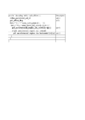
- FIG. 3 is a diagram illustrating a configuration of encoded data of parallel decode information.
- pdi_unreferenced_region_ctu_horizontal [i] [j] and pdi_unreferenced_region_ctu_vertical [i] [j] are syntax elements for indicating a non-referenceable range.
- pdi_unreferenced_region_ctu_horizontal [i] [j] is a horizontal offset indicating a non-referenceable range when the target view i (first layer) refers to the reference view j (second layer)
- pdi_unreferenced_region_ctu_vertical [i] [j] is a vertical offset indicating a non-referenceable range when the target view i refers to the reference view j.
- the horizontal offset and the vertical offset each indicate an offset from the upper left reference CTB of the reference non-referenceable range of the reference view j when decoding the target CTB of the target view i.
- the unit of offset is CTB unit. Further, it may be defined that the delay from the decoding of the reference CTB of the reference view j to the decoding of the target view i is expressed as an offset between the target CTB of the target view and the reference CTB. It is equivalent.
- pdi_offset_flag is a syntax element (adjustment flag) for adjusting the unreferenceable range.
- the unreferenceable range unreferenced region [i] [j] is a range that cannot be used as a reference range when a certain target view i refers to another reference view j.
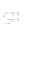
- FIG. 4 are diagrams showing a first non-referenceable range, a second non-referenceable range, and a non-referenceable range unreferenced region [i] [j], respectively.
- the non-referenceable range includes only the first non-referenceable range, or includes the first non-referenceable range and the second non-referenceable range.
- both the first non-referenceable range and the second non-referenceable range are defined, the sum of the first non-referenceable range and the second non-referenceable range becomes the non-referenceable range.
- both the first non-referenceable range and the second non-referenceable range are not defined, there is no non-referenceable range. That is, any area can be referred to.
- the first non-referenceable range is defined when a syntax element pdi_unreferenced_region_ctu_vertical that is an offset in the vertical direction of parallel decode information is greater than zero. It is not defined when pdi_unreferenced_region_ctu_vertical is 0.
- the vertical offset pdi_unreferenced_region_ctu_vertical indicates the vertical restriction range of the first non-referenceable range.
- the Y coordinate of the upper left coordinate of the first unreferenceable range is a value obtained by multiplying the sum of the Y coordinate yCtb of the CTB coordinate of the target block and the offset in the vertical direction by the CTB size CtbSizeY, and the X coordinate of the upper left coordinate is 0. Yes, the lower right coordinate of the reference impossible range is the lower right of the screen.
- XUnref x_min ... x_max indicates that the x coordinate is x_min or more and x_max or less
- yUnref y_min ... y_max indicates that the y coordinate is y_min or more and y_max or less.
- pic_width_in_luma_samples indicates the horizontal width of the luminance component of the picture.
- pic_height_in_luma_samples indicates the height of the luminance component of the picture.
- CtbAddrInRs indicates how many CTBs the target CTB corresponds to in the raster scan order in the picture.
- PicWidthInCtbsY is a value obtained by dividing the height of the target view by the CTB size.
- CtbSizeY is the CTB size of the target view.
- PdiOffsetVal is an offset determined by the following equation based on the value of the syntax element pdi_offset_flag indicating whether or not to adjust the parallel decode information by the loop filter.
- PdiOffsetVal pdi_offset_flag * 8 PdiOffsetVal corresponds to a change in the necessary non-referenceable range depending on whether a loop filter is applied on the reference view.
- the application range of the normal deblocking filter is usually 3 pixels, and the application range of the adaptive offset filter is 1 pixel.
- the adaptive offset filter is involved in the view, it is necessary to increase the non-referenceable range. Therefore, when pdi_offset_flag is 1, PdiOffsetVal is 4, and when pdi_offset_flag is 0, PdiOffsetVal is set to 0.
- the loop filter processing of the horizontal boundary located at the bottom of the CTB and the vertical boundary located at the right of the CTB includes the CTB and right It is necessary to wait for the decoding of the next CTB located at. That is, when referring to pixels near the boundary, the delay due to decoding wait increases.
- this range is excluded to prevent an increase in delay.
- the second non-referenceable range is defined when the syntax element pdi_unreferenced_region_ctu_horizontal, which is the horizontal offset of the parallel decode information, is greater than zero. Not defined when pdi_unreferenced_region_ctu_horizontal is 0.
- the horizontal offset pdi_unreferenced_region_ctu_horizontal indicates the horizontal restriction range of the second non-referenceable range.
- the second non-referenceable range is a rectangular region defined by the vertical offset pdi_unreferenced_region_ctu_vertical [i] [j] and the horizontal offset pdi_unreferenced_region_ctu_horizontal [i] [j].
- the Y coordinate of the upper left coordinate of the second non-referenceable range is a value obtained by multiplying the sum of the Y coordinate yCtb of the target block CTB coordinate and the offset in the vertical direction by 1 and the CTB size CtbSizeY, and the upper left coordinate.
- the X coordinate is a value obtained by multiplying the X coordinate xCtb of the CTB coordinate of the target block and the offset in the vertical direction by the CTB size CtbSizeY.
- XCtb and yCtb indicate the X and Y coordinates of the CTB including the target block on the target view, and use the CTB address CtbAddrInRs of the target block, the screen size PicWidthInCtbsY according to the CTB size of the target view, and the CTB size CtbSizeY. It is derived from the following equation.
- xCtb (CtbAddrInRs% PicWidthInCtbsY) * CtbSizeY
- yCtb (CtbAddrInRs / PicWidthInCtbsY) * CtbSizeY (Modification of non-referenceable range)
- Indicates below y_max By indicating the range of the X and Y coordinates, a rectangular range is indicated (the same applies hereinafter).
- PicHeightInCtbsY is a value obtained by dividing the screen height of the target view by the CTB size.
- the second non-referenceable range is not defined when pdi_unreferenced_region_ctu_horizontal is 0, and is defined as follows when it is greater than 0.
- PicHeightInCtbsY-1 CtbAddrX and CtbAddrY indicate the CTB coordinate in the X direction and the CTB coordinate in the Y direction of the CTB including the target block on the target view, and use the CTB address CtbAddrInRs of the target block and the screen size PicWidthInCtbsY according to the CTB size of the target view.
- the following formula is used.
- CtbAddrX CtbAddrInRs% PicWidthInCtbsY
- CtbAddrY CtbAddrInRs / PicWidthInCtbsY (Picture layer)
- the picture PICT includes slices S0 to SNS-1 (NS is the total number of slices included in the picture PICT).
- slice layer In the slice layer, a set of data referred to by the image decoding device 31 for decoding the slice S to be processed (also referred to as a target slice) is defined. As shown in FIG. 2C, the slice S includes a slice header SH and slice data SDATA.
- the slice header SH includes a coding parameter group that the image decoding device 31 refers to in order to determine a decoding method of the target slice.
- the slice type designation information (slice_type) that designates the slice type is an example of an encoding parameter included in the slice header SH.
- I slice using only intra prediction at the time of encoding (2) P slice using unidirectional prediction or intra prediction at the time of encoding, (3) B-slice using unidirectional prediction, bidirectional prediction, or intra prediction at the time of encoding may be used.
- the slice header SH may include a reference (pic_parameter_set_id) to the picture parameter set PPS included in the sequence layer.
- the slice data layer a set of data referred to by the image decoding device 31 in order to decode the slice data SDATA to be processed is defined.
- the slice data SDATA includes a coded tree block (CTB) as shown in FIG.
- CTB is a fixed-size block (for example, 64 ⁇ 64) constituting a slice, and may be called a maximum coding unit (LCU).
- the coding tree layer defines a set of data that the image decoding device 31 refers to in order to decode the coding tree block to be processed.
- the coding tree unit is divided by recursive quadtree division.
- a node having a tree structure obtained by recursive quadtree partitioning is referred to as a coding tree.
- An intermediate node of the quadtree is a coded tree unit (CTU), and the coded tree block itself is also defined as the highest CTU.
- the CTU includes a split flag (split_flag). When the split_flag is 1, the CTU is split into four coding tree units CTU.
- the coding tree unit CTU is divided into four coding units (CU: Coded Unit).
- the coding unit CU is a terminal node of the coding tree layer and is not further divided in this layer.
- the encoding unit CU is a basic unit of the encoding process.
- the size of the encoding unit is any of 64 ⁇ 64 pixels, 32 ⁇ 32 pixels, 16 ⁇ 16 pixels, and 8 ⁇ 8 pixels. It can take.
- the encoding unit layer defines a set of data referred to by the image decoding device 31 in order to decode the processing target encoding unit.
- the encoding unit includes a CU header CUH, a prediction tree, a conversion tree, and a CU header CUF.
- the CU header CUH it is defined whether the coding unit is a unit using intra prediction or a unit using inter prediction.
- the coding unit is the root of a prediction tree (PT) and a transformation tree (TT).
- the CU header CUF is included between the prediction tree and the conversion tree or after the conversion tree.
- the coding unit is divided into one or a plurality of prediction blocks, and the position and size of each prediction block are defined.
- the prediction block is one or a plurality of non-overlapping areas constituting the coding unit.
- the prediction tree includes one or a plurality of prediction blocks obtained by the above division.
- Prediction processing is performed for each prediction block.
- a prediction block which is a unit of prediction is also referred to as a prediction unit (PU).
- Intra prediction is prediction within the same picture
- inter prediction refers to prediction processing performed between different pictures (for example, between display times and between layer images).
- the division method is encoded by part_mode of encoded data, and 2N ⁇ 2N (the same size as the encoding unit), 2N ⁇ N, 2N ⁇ nU, 2N ⁇ nD, N ⁇ 2N, nL X2N, nRx2N, and NxN.
- 2N ⁇ nU indicates that a 2N ⁇ 2N encoding unit is divided into two regions of 2N ⁇ 0.5N and 2N ⁇ 1.5N in order from the top.
- 2N ⁇ nD indicates that a 2N ⁇ 2N encoding unit is divided into two regions of 2N ⁇ 1.5N and 2N ⁇ 0.5N in order from the top.
- nL ⁇ 2N indicates that a 2N ⁇ 2N encoding unit is divided into two regions of 0.5N ⁇ 2N and 1.5N ⁇ 2N in order from the left.
- nR ⁇ 2N indicates that a 2N ⁇ 2N encoding unit is divided into two regions of 1.5N ⁇ 2N and 0.5N ⁇ 1.5N in order from the left. Since the number of divisions is one of 1, 2, and 4, PUs included in the CU are 1 to 4. These PUs are expressed as PU0, PU1, PU2, and PU3 in order.
- the encoding unit is divided into one or a plurality of transform blocks, and the position and size of each transform block are defined.
- the transform block is one or a plurality of non-overlapping areas constituting the encoding unit.
- the conversion tree includes one or a plurality of conversion blocks obtained by the above division.
- the division in the transformation tree includes the one in which an area having the same size as that of the encoding unit is assigned as the transformation block, and the one in the recursive quadtree division like the above-described division in the tree block.
- a conversion block that is a unit of conversion is also referred to as a conversion unit (TU).
- the prediction image of the prediction unit is derived by a prediction parameter associated with the prediction unit.
- the prediction parameters include a prediction parameter for intra prediction or a prediction parameter for inter prediction.
- prediction parameters for inter prediction inter prediction (inter prediction parameters) will be described.
- the inter prediction parameter includes prediction list use flags predFlagL0 and predFlagL1, reference picture indexes refIdxL0 and refIdxL1, and vectors mvL0 and mvL1.
- the prediction list use flags predFlagL0 and predFlagL1 are flags indicating whether or not reference picture lists called L0 list and L1 list are used, respectively, and a reference picture list corresponding to a value of 1 is used.
- prediction list use flag information can also be expressed by an inter prediction flag inter_pred_idx described later. Normally, a prediction list use flag is used in a prediction image generation unit and a prediction parameter memory described later, and an inter prediction flag inter_pred_idx is used when decoding information on which reference picture list is used from encoded data. It is done.
- Syntax elements for deriving the inter prediction parameters included in the encoded data include, for example, a partition mode part_mode, a merge flag merge_flag, a merge index merge_idx, an inter prediction flag inter_pred_idx, a reference picture index refIdxLX, a prediction vector index mvp_LX_idx, and a difference There is a vector mvdLX.
- the reference picture list is a sequence of reference pictures stored in the reference picture memory 306 (FIG. 6).
- FIG. 5 is a conceptual diagram illustrating an example of a reference picture list.
- the codes P1, P2, Q0, P3, and P4 shown in order from the left end to the right are codes indicating the respective reference pictures.
- P such as P1 indicates the viewpoint P
- Q of Q0 indicates a viewpoint Q different from the viewpoint P.
- the subscripts P and Q indicate the picture order number POC.
- a downward arrow directly below refIdxLX indicates that the reference picture index refIdxLX is an index that refers to the reference picture Q0 in the reference picture memory 306.
- FIG. 4 is a conceptual diagram illustrating an example of a reference picture.
- the horizontal axis indicates the display time
- the vertical axis indicates the viewpoint.
- the rectangles shown in FIG. 4 with 2 rows and 3 columns (6 in total) indicate pictures.
- the rectangle in the second column from the left in the lower row indicates a picture to be decoded (target picture), and the remaining five rectangles indicate reference pictures.
- a reference picture Q0 indicated by an upward arrow from the target picture is a picture that has the same display time as the target picture and a different viewpoint. In the displacement prediction based on the target picture, the reference picture Q0 is used.
- a reference picture P1 indicated by a left-pointing arrow from the target picture is a past picture at the same viewpoint as the target picture.
- a reference picture P2 indicated by a right-pointing arrow from the target picture is a future picture at the same viewpoint as the target picture. In motion prediction based on the target picture, the reference picture P1 or P2 is used.
- FIG. 6 is a schematic diagram illustrating a configuration of the image decoding device 31 according to the present embodiment.
- the image decoding device 31 includes an entropy decoding unit 301, a prediction parameter decoding unit 302, a reference picture memory (reference image storage unit, frame memory) 306, a prediction parameter memory (prediction parameter storage unit, frame memory) 307, and a prediction image generation unit 308.
- the prediction parameter decoding unit 302 includes an inter prediction parameter decoding unit 303 and an intra prediction parameter decoding unit 304.
- the predicted image generation unit 308 includes an inter predicted image generation unit 309 and an intra predicted image generation unit 310.
- the entropy decoding unit 301 performs entropy decoding on the encoded stream Te input from the outside, and separates and decodes individual codes (syntax elements).
- the separated codes include prediction information for generating a prediction image and residual information for generating a difference image.
- the entropy decoding unit 301 outputs a part of the separated code to the prediction parameter decoding unit 302.
- Some of the separated codes are, for example, a prediction mode PredMode, a split mode part_mode, a merge flag merge_flag, a merge index merge_idx, an inter prediction flag inter_pred_idx, a reference picture index refIdxLX, a prediction vector index mvp_LX_idx, and a difference vector mvdLX.
- Control of which code to decode is performed based on an instruction from the prediction parameter decoding unit 302.
- the entropy decoding unit 301 outputs the quantization coefficient to the inverse quantization / inverse DCT unit 311.
- This quantization coefficient is a coefficient obtained by performing DCT (Discrete Cosine Transform, Discrete Cosine Transform) on the residual signal and quantizing it in the encoding process.
- the entropy decoding unit 301 includes an SEI decoding unit.
- the SEI decoding unit decodes SEI including the parallel decoding information defined in FIG. 3 and transmits the SEI to the inter-predicted image generation unit 309.
- the inter prediction parameter decoding unit 303 decodes the inter prediction parameter with reference to the prediction parameter stored in the prediction parameter memory 307 based on the code input from the entropy decoding unit 301.
- the inter prediction parameter decoding unit 303 outputs the decoded inter prediction parameter to the prediction image generation unit 308 and stores it in the prediction parameter memory 307. Details of the inter prediction parameter decoding unit 303 will be described later.
- the intra prediction parameter decoding unit 304 refers to the prediction parameter stored in the prediction parameter memory 307 on the basis of the code input from the entropy decoding unit 301 and decodes the intra prediction parameter.
- the intra prediction parameter is a parameter used in a process of predicting a picture block within one picture, for example, an intra prediction mode IntraPredMode.
- the intra prediction parameter decoding unit 304 outputs the decoded intra prediction parameter to the prediction image generation unit 308 and stores it in the prediction parameter memory 307.
- the reference picture memory 306 stores the reference picture block (reference picture block) generated by the adding unit 312 at a predetermined position for each picture and block to be decoded.
- the prediction parameter memory 307 stores the prediction parameter in a predetermined position for each decoding target picture and block. Specifically, the prediction parameter memory 307 stores the inter prediction parameter decoded by the inter prediction parameter decoding unit 303, the intra prediction parameter decoded by the intra prediction parameter decoding unit 304, and the prediction mode predMode separated by the entropy decoding unit 301. .
- the stored inter prediction parameters include, for example, a prediction list utilization flag predFlagLX (inter prediction flag inter_pred_idx), a reference picture index refIdxLX, and a vector mvLX.
- the prediction image generation unit 308 receives the prediction mode predMode input from the entropy decoding unit 301 and the prediction parameter from the prediction parameter decoding unit 302. Further, the predicted image generation unit 308 reads a reference picture from the reference picture memory 306. The predicted image generation unit 308 generates a predicted picture block P (predicted image) using the input prediction parameter and the read reference picture in the prediction mode indicated by the prediction mode predMode.
- the inter prediction image generation unit 309 uses the inter prediction parameter input from the inter prediction parameter decoding unit 303 and the read reference picture to perform the prediction picture block P by inter prediction. Is generated.
- the predicted picture block P corresponds to the PU.
- the PU corresponds to a part of a picture composed of a plurality of pixels as a unit for performing the prediction process as described above, that is, a decoding target block on which the prediction process is performed at a time.
- the inter predicted image generation unit 309 For the reference picture list (L0 list or L1 list) for which the prediction list use flag predFlagLX is 1, the inter predicted image generation unit 309 generates a vector mvLX based on the decoding target block from the reference picture indicated by the reference picture index refIdxLX. The reference picture block at the position indicated by is read from the reference picture memory 306. The inter prediction image generation unit 309 performs prediction on the read reference picture block to generate a prediction picture block P. The inter prediction image generation unit 309 outputs the generated prediction picture block P to the addition unit 312.
- the inter prediction image generation unit 309 includes a prediction picture block decoding standby unit.
- the prediction picture block decoding standby unit determines whether or not the specific CTB of the reference picture has been decoded according to the parallel decoding information.
- the process waits without generating the predicted picture block P, and the predicted picture block P is generated after the specific CTB of the reference picture is decoded.
- the coordinates (xRefCtb, yRefCtb) of the specific CTB of the reference picture are derived by the following equations.
- xRefCtb min (((xCtb + pdi_unreferenced_region_ctu_horizontal [i] [j] * CtbSizeY + refCtbSizeY-1) / refCtbSizeY-1) * refCtbSizeY, (refPicWidthInCtbsY * refCtbSizeY)
- yRefCtb min (((yCtb +-(pdi_unreferenced_region_ctu_vertical [i] [j]-1) * CtbSizeY + refCtbSizeY-1) / refCtbSizeY-1) * refCtbSizeY, (refPicHeightInCtbsY * refCtbSizeY)
- xRefCtb is set to the C
- xRefCtb (refPicWidthInCtbsY-1) * refCtbSizeY (Modified example of prediction picture block decoding standby unit)
- the coordinates of the specific CTB can be defined not in units of pixels but in units of the reference view CTB size refCtbSizeY (corresponding to definition 2 of the non-referenceable range).
- the coordinates (xRefCtb, yRefCtb) of the specific CTB of the reference picture are derived by the following equations.
- xRefCtb min (((xCtb + pdi_unreferenced_region_ctu_horizontal [i] [j] * CtbSizeY + refCtbSizeY-1) / refCtbSizeY-1), (refPicWidthInCtbsY-1))
- yRefCtb min (((yCtb + (pdi_unreferenced_region_ctu_vertical [i] [j]-1) * CtbSizeY + refCtbSizeY-1) / refCtbSizeY-1), (refPicHeightInCtbsY-1))
- xRefCtb is set as follows.
- the intra predicted image generation unit 310 performs intra prediction using the intra prediction parameter input from the intra prediction parameter decoding unit 304 and the read reference picture. Specifically, the intra predicted image generation unit 310 reads, from the reference picture memory 306, a reference picture block that is a decoding target picture and is in a predetermined range from the decoding target block among blocks that have already been decoded.
- the predetermined range is, for example, any of the left, upper left, upper, and upper right adjacent blocks when the decoding target block sequentially moves in a so-called raster scan order, and varies depending on the intra prediction mode.
- the raster scan order is an order in which each row is sequentially moved from the left end to the right end in each picture from the upper end to the lower end.
- the intra predicted image generation unit 310 performs prediction in the prediction mode indicated by the intra prediction mode IntraPredMode for the read reference picture block, and generates a predicted picture block.
- the intra predicted image generation unit 310 outputs the generated predicted picture block P to the addition unit 312.
- the inverse quantization / inverse DCT unit 311 inversely quantizes the quantization coefficient input from the entropy decoding unit 301 to obtain a DCT coefficient.
- the inverse quantization / inverse DCT unit 311 performs inverse DCT (Inverse Discrete Cosine Transform) on the obtained DCT coefficient to calculate a decoded residual signal.
- the inverse quantization / inverse DCT unit 311 outputs the calculated decoded residual signal to the addition unit 312 and the residual storage unit 313.
- the adder 312 outputs the prediction picture block P input from the inter prediction image generation unit 309 and the intra prediction image generation unit 310 and the signal value of the decoded residual signal input from the inverse quantization / inverse DCT unit 311 for each pixel. Addition to generate a reference picture block.
- the adder 312 stores the generated reference picture block in the reference picture memory 306, and outputs a decoded layer image Td in which the generated reference picture block is integrated for each picture to the outside.
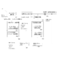
- FIG. 7 is a diagram for explaining the parallel decoding operation.
- FIG. 7B shows an example in which layer 1 is decoded with a delay corresponding to the delay indicated by the parallel decode information from layer 0.
- the arrows indicate areas where the respective layer images are decoded.
- the tip of the arrow indicates the right end of the block currently being decoded, and the target CTB is the decoding target in layer 1.
- the shaded portion indicates a referenceable range that is a referenceable area among the decoded areas in the image of the layer 0, and the vertical stripe part cannot be referred to Indicates the range.
- the prediction picture block decoding standby unit determines whether or not the decoding of the specific CTB indicated by the coordinates (xRefCtb, yRefCtb) of the image of layer 0 is completed, and the specific CTB is not decoded First, decoding of the target CTB is waited, and decoding of the target CTB is started after decoding of the specific CTB is completed.
- the reference range can be limited depending on whether or not the target view is related to the loop filter.
- Parallel decoding ultra-low delay decoding
- the parallelism of the decoding process is improved, and the processing time is shortened.
- FIG. 8 is a block diagram illustrating a configuration of the image encoding device 11 according to the present embodiment.
- the image encoding device 11 includes a prediction image generation unit 101, a subtraction unit 102, a DCT / quantization unit 103, an entropy encoding unit 104, an inverse quantization / inverse DCT unit 105, an addition unit 106, a prediction parameter memory (prediction parameter storage). Unit, frame memory) 108, reference picture memory (reference image storage unit, frame memory) 109, coding parameter determination unit 110, prediction parameter coding unit 111, and residual storage unit 313 (residual recording unit). Is done.
- the prediction parameter encoding unit 111 includes an inter prediction parameter encoding unit 112 and an intra prediction parameter encoding unit 113.
- the predicted image generation unit 101 generates a predicted picture block P for each block which is an area obtained by dividing the picture for each viewpoint of the layer image T input from the outside.
- the predicted image generation unit 101 reads the reference picture block from the reference picture memory 109 based on the prediction parameter input from the prediction parameter encoding unit 111.
- the prediction parameter input from the prediction parameter encoding unit 111 is, for example, a motion vector or a displacement vector.
- the predicted image generation unit 101 reads the reference picture block of the block at the position indicated by the motion vector or the displacement vector predicted from the encoding target block.
- the prediction image generation unit 101 generates a prediction picture block P using one prediction method among a plurality of prediction methods for the read reference picture block.
- the predicted image generation unit 101 outputs the generated predicted picture block P to the subtraction unit 102. Note that since the predicted image generation unit 101 performs the same operation as the predicted image generation unit 308 already described, details of generation of the predicted picture block P are omitted.
- the predicted image generation unit 101 calculates an error value based on a difference between a signal value for each pixel of a block included in the layer image and a signal value for each corresponding pixel of the predicted picture block P. Select the prediction method to minimize.
- the method for selecting the prediction method is not limited to this.
- the plurality of prediction methods are intra prediction, motion prediction, and merge prediction.
- Motion prediction is prediction between display times among the above-mentioned inter predictions.
- the merge prediction is a prediction that uses the same reference picture block and prediction parameter as a block that has already been encoded and is within a predetermined range from the encoding target block.
- the plurality of prediction methods are intra prediction, motion prediction, merge prediction, and displacement prediction.
- the displacement prediction (disparity prediction) is prediction between different layer images (different viewpoint images) in the above-described inter prediction.
- the prediction image generation unit 101 outputs a prediction mode predMode indicating the intra prediction mode used when generating the prediction picture block P to the prediction parameter encoding unit 111 when intra prediction is selected.
- the predicted image generation unit 101 when selecting motion prediction, stores the motion vector mvLX used when generating the predicted picture block P in the prediction parameter memory 108 and outputs the motion vector mvLX to the inter prediction parameter encoding unit 112.
- the motion vector mvLX indicates a vector from the position of the encoding target block to the position of the reference picture block when the predicted picture block P is generated.
- the information indicating the motion vector mvLX may include information indicating a reference picture (for example, a reference picture index refIdxLX, a picture order number POC), and may represent a prediction parameter.
- the predicted image generation unit 101 outputs a prediction mode predMode indicating the inter prediction mode to the prediction parameter encoding unit 111.
- the prediction image generation unit 101 When the prediction image generation unit 101 selects the displacement prediction, the prediction image generation unit 101 stores the displacement vector used when generating the prediction picture block P in the prediction parameter memory 108 and outputs it to the inter prediction parameter encoding unit 112.
- the displacement vector dvLX indicates a vector from the position of the encoding target block to the position of the reference picture block when the predicted picture block P is generated.
- the information indicating the displacement vector dvLX may include information indicating a reference picture (for example, reference picture index refIdxLX, view IDview_id) and may represent a prediction parameter.
- the predicted image generation unit 101 outputs a prediction mode predMode indicating the inter prediction mode to the prediction parameter encoding unit 111.
- the prediction image generation unit 101 selects merge prediction
- the prediction image generation unit 101 outputs a merge index merge_idx indicating the selected reference picture block to the inter prediction parameter encoding unit 112. Further, the predicted image generation unit 101 outputs a prediction mode predMode indicating the merge prediction mode to the prediction parameter encoding unit 111.
- the subtraction unit 102 subtracts the signal value of the prediction picture block P input from the prediction image generation unit 101 for each pixel from the signal value of the corresponding block of the layer image T input from the outside, and generates a residual signal. Generate.
- the subtraction unit 102 outputs the generated residual signal to the DCT / quantization unit 103 and the encoding parameter determination unit 110.
- the DCT / quantization unit 103 performs DCT on the residual signal input from the subtraction unit 102 and calculates a DCT coefficient.
- the DCT / quantization unit 103 quantizes the calculated DCT coefficient to obtain a quantization coefficient.
- the DCT / quantization unit 103 outputs the obtained quantization coefficient to the entropy encoding unit 104 and the inverse quantization / inverse DCT unit 105.
- the entropy coding unit 104 receives the quantization coefficient from the DCT / quantization unit 103 and the coding parameter from the coding parameter determination unit 110.
- Input encoding parameters include codes such as a reference picture index refIdxLX, a vector index mvp_LX_idx, a difference vector mvdLX, a prediction mode predMode, and a merge index merge_idx.
- the entropy encoding unit 104 generates an encoded stream Te by entropy encoding the input quantization coefficient and encoding parameter, and outputs the generated encoded stream Te to the outside.
- the entropy encoding unit 104 includes an SEI encoding unit.
- the SEI encoding unit encodes the parallel decoding information.
- the encoded parallel decoding information is included in the encoded stream Te.
- the inverse quantization / inverse DCT unit 105 inversely quantizes the quantization coefficient input from the DCT / quantization unit 103 to obtain a DCT coefficient.
- the inverse quantization / inverse DCT unit 105 performs inverse DCT on the obtained DCT coefficient to calculate a decoded residual signal.
- the inverse quantization / inverse DCT unit 105 outputs the calculated decoded residual signal to the addition unit 106.
- the addition unit 106 adds the signal value of the predicted picture block P input from the predicted image generation unit 101 and the signal value of the decoded residual signal input from the inverse quantization / inverse DCT unit 105 for each pixel, and refers to them. Generate a picture block.
- the adding unit 106 stores the generated reference picture block in the reference picture memory 109.
- the prediction parameter memory 108 stores the prediction parameter generated by the prediction parameter encoding unit 111 at a predetermined position for each picture and block to be encoded.
- the reference picture memory 109 stores the reference picture block generated by the adding unit 106 at a predetermined position for each picture and block to be encoded.
- the encoding parameter determination unit 110 selects one set from among a plurality of sets of encoding parameters.
- the encoding parameter is a parameter to be encoded that is generated in association with the above-described prediction parameter or the prediction parameter.
- the predicted image generation unit 101 generates a predicted picture block P using each of these sets of encoding parameters.
- the encoding parameter determination unit 110 includes a prediction parameter restriction unit.
- the encoding parameter determination unit 110 calculates a cost value indicating the amount of information and the encoding error for each of a plurality of sets.
- the cost value is, for example, the sum of a code amount and a square error multiplied by a coefficient ⁇ .
- the code amount is the information amount of the encoded stream Te obtained by entropy encoding the quantization error and the encoding parameter.
- the square error is the sum between pixels regarding the square value of the residual value of the residual signal calculated by the subtracting unit 102.
- the coefficient ⁇ is a real number larger than a preset zero.
- the encoding parameter determination unit 110 selects a set of encoding parameters that minimizes the calculated cost value.
- the entropy encoding unit 104 outputs the selected set of encoding parameters to the outside as the encoded stream Te, and does not output the set of unselected encoding parameters.
- the prediction parameter restriction unit determines whether or not the prediction parameter in the encoding parameters that are selection candidates does not exceed the restriction range. Specifically, the prediction parameter restriction unit, in accordance with the parallel decoding information encoded by the SEI encoding unit, when the prediction parameter specifies the reference view j as the reference destination of the target view i, the reference impossible range It is determined whether or not the vector mvLX included in the prediction parameter does not exceed a predetermined range so as not to refer to the reference range indicated by unreferenced region [i] [j].
- the prediction parameter restriction unit determines whether or not the first reference impossible range is included by the following determination.
- the restriction may be changed depending on whether motion compensation is performed by the motion compensation filter, that is, whether the motion vector is a vector indicating an integer position. Specifically, when the motion vector is 1/4 pel precision and mvLX [1] is a multiple of 4, the following expression is used as the determination expression.
- the prediction parameter restriction unit determines whether or not the second reference impossible range is included by the following determination.
- the restriction may be changed depending on whether or not the motion vector is a vector in which the motion vector indicates an integer position, as in the first non-referenceable range.
- the motion vector is 1/4 pel accuracy and mvLX [1] is a multiple of 4, the following expression is used as the determination expression.
- the encoding parameter determination unit 110 excludes prediction parameters that exceed the limit range from selection candidates, and does not output them finally as encoding parameters. Conversely, the encoding parameter determination unit 110 selects an encoding parameter from prediction parameters that do not exceed the limit range.
- the prediction parameter encoding unit 111 derives a prediction parameter used when generating a prediction picture based on the parameter input from the prediction image generation unit 101, and encodes the derived prediction parameter to generate a set of encoding parameters. To do.
- the prediction parameter encoding unit 111 outputs the generated set of encoding parameters to the entropy encoding unit 104.
- the prediction parameter encoding unit 111 stores, in the prediction parameter memory 108, a prediction parameter corresponding to the set of the generated encoding parameters selected by the encoding parameter determination unit 110.
- the prediction parameter encoding unit 111 operates the inter prediction parameter encoding unit 112 when the prediction mode predMode input from the prediction image generation unit 101 indicates the inter prediction mode.
- the prediction parameter encoding unit 111 operates the intra prediction parameter encoding unit 113 when the prediction mode predMode indicates the intra prediction mode.
- the inter prediction parameter encoding unit 112 derives an inter prediction parameter based on the prediction parameter input from the encoding parameter determination unit 110.
- the inter prediction parameter encoding unit 112 includes the same configuration as the configuration in which the inter prediction parameter decoding unit 303 (see FIG. 6 and the like) derives the inter prediction parameter as a configuration for deriving the inter prediction parameter.
- the configuration of the inter prediction parameter encoding unit 112 will be described later.
- the intra prediction parameter encoding unit 113 determines the intra prediction mode IntraPredMode indicated by the prediction mode predMode input from the encoding parameter determination unit 110 as a set of inter prediction parameters.
- Non-Patent Document 1 it is necessary to consider the difference in the CTB size between the target view and the reference view when determining whether or not the reference impossible range is referenced.
- the present embodiment since only the CTB size of the target view is referred to in the determination formula, it does not depend on the parameters of the reference view. Thereby, there exists an effect that determination processing is simplified.
- the configuration of the encoded data of the parallel decode information in this embodiment is the same as that in FIG. However, the difference is that the syntax elements pdi_unreferenced_region_ctu_vertical and pdi_unreferenced_region_ctu_horizontal, which are offsets indicating the non-referenceable range, are set based on the CTB size refCtbSizeY of the reference view, and accordingly, the method of setting the non-referenceable range is also different.
- the CTB coordinates refCtbAddrX and refCtbAddrY on the reference view are defined by the following formula.
- refCtbAddrX (CtbAddrInRS% PicWidthInCtbsY) * CtbSizeY / refCtbSizeY)
- refCtbAddrY (CtbAddrInRS / PicWidthInCtbsY) * CtbSizeY / refCtbSizeY)
- the CTB coordinates CtbAddrInRs derived from the CTB address CtbAddrInRs of the target block and the screen size PicWidthInCtbsY based on the CTB size of the target view (CtbAddrInRS% PicWidthInCtbsY, CtbAddrInRS / PicWidthInCtbsY) are derived, and the CTB coordinates of the target view CTB Derived by multiplying by size CtbSizeY and then dividing by reference view CTB size refCtbSizeY.
- CtbSizeY / refCtbSizeY is larger than 1
- the CTB coordinates refCtbAddrX and refCtbAddrY on the reference view are larger than the CTB coordinates of the target view. Also grows.
- the first non-referenceable range is not defined when pdi_unreferenced_region_ctu_vertical is 0, and is defined as follows when it is greater than 0.
- the second non-referenceable range is not defined when pdi_unreferenced_region_ctu_horizontal is 0, and is defined as follows when greater than 0.
- the CTB coordinates refCtbAddrX and refCtbAddrY on the reference view are defined by the following formula.
- refCtbAddrX (CtbAddrInRS% PicWidthInCtbsY) * CtbSizeY / refCtbSizeY)
- refCtbAddrY (CtbAddrInRS / PicWidthInCtbsY) * CtbSizeY / refCtbSizeY)
- the first non-referenceable range is not defined when pdi_unreferenced_region_ctu_vertical is 0, and is defined as follows when greater than 0.
- xUnrefCtb 0..PicWidthInCtbsY-1
- yUnrefCtb refCtbAddrY + (pdi_unreferenced_region_ctu_vertical [i] [j]) .. PicHeightInCtbsY-1
- the first non-referenceable range is expressed by the CTB address refCtbAddr of the start CTB that is the first CTB accessed within the first non-referenceable range when the image is scanned in raster scan order in CTB units. Is also possible.
- the CTB address refCtbAddr of the start CTB is defined as follows.
- refCtbAddr (refCtbAddrY + pdi_unreferenced_region_ctu_vertical [i] [j]) * refPicWidthInCtbsY
- the first non-referenceable range is a rectangular region defined by the vertical offset pdi_unreferenced_region_ctu_vertical [i] [j].
- the start CTB address of the first non-referenceable range is defined by a value obtained by multiplying the Y coordinate refCtbAddrY of the reference CTB address and the vertical offset by the CTB width refPicWidthInCtbs of the reference picture, and the Y coordinate refCtbAddrY of the reference CTB address is It is defined by a value obtained by multiplying the Y coordinate yCtb of the CTB coordinate of the target block by the CTB size CtbSizeY of the target picture and dividing by the CTB size refCtbSizeY of the reference picture.
- the second non-referenceable range is not defined when pdi_unreferenced_region_ctu_horizontal is 0, and is defined as follows when it is greater than 0.
- the CTB address refCtbAddr of the start CTB is defined as follows.
- refCtbAddr (refCtbAddrY + pdi_unreferenced_region_ctu_vertical [i] [j]-1) * refPicWidthInCtbsY + min (refCtbAddrX + pdi_unreferenced_region_ctu_horizontal [i] [j], refPicWidthInCtbsY-1)
- the second non-referenceable range is a region defined by a vertical offset pdi_unreferenced_region_ctu_vertical [i] [j] and a horizontal offset pdi_unreferenced_region_ctu_horizontal [i] [j].
- the starting CTB address of the second non-referenceable range is obtained by multiplying the value obtained by subtracting 1 from the sum of the Y coordinate refCtbAddrY of the reference CTB address and the offset in the vertical direction and the CTB width refPicWidthInCtbs of the reference picture X
- the Y coordinate refCtbAddrY of the reference CTB address is defined as the sum of the coordinate refCtbAddrX and the horizontal offset plus the minimum value of the CTB width refPicWidthInCtb of the reference picture minus 1.
- the coordinate yCtb is defined by a value obtained by multiplying the CTB size CtbSizeY of the target picture by the CTB size refCtbSizeY of the reference picture
- the X coordinate refCtbAddrX of the reference CTB address is the CTB coordinate XCtb of the target block and the CTB size of the target picture It is defined by a value obtained by multiplying by CtbSizeY and dividing by the CTB size refCtbSizeY of the reference picture.
- the image decoding device 31B in this embodiment is different from the image decoding device 31 only in that the inter-predicted image generation unit 309 includes a predicted picture block decoding standby unit B instead of the predicted picture block decoding standby unit.
- the prediction picture block decoding standby unit B differs from the prediction picture block decoding standby unit in the method of deriving the coordinates (xRefCtb, yRefCtb) of the specific CTB.
- the coordinates (xRefCtb, yRefCtb) of the specific CTB of the reference picture are derived by the following equations.
- xRefCtb min (((xCtb + pdi_unreferenced_region_ctu_horizontal [i] [j] * refCtbSizeY, (pic_width_in_luma_samples-1) / refCtbSizeY * refCtbSizeY)
- yRefCtb min (((yCtb + (pdi_unreferenced_region_ctu_vertical [i] [j]-1) * refCtbSizeY, (pic_height_in_luma_samples-1) / refCtbSizeY * refCtbSizeY)
- xRefCtb is set as follows.
- xRefCtb (refPicWidthInCtbsY-1) * refCtbSizeY) (Modified example of prediction picture block decoding standby unit B)
- the coordinates of the specific CTB can be defined not in units of pixels but in units of reference view CTB size refCtbSizeY. In that case, when the predicted picture block P belonging to the target view i refers to the reference picture of the reference view j, the coordinates (xRefCtb, yRefCtb) of the specific CTB of the reference picture are derived by the following equations.
- xRefCtb min (((xCtb + pdi_unreferenced_region_ctu_horizontal [i] [j], (refPicWidthInCtbsY-1))
- yRefCtb min (((yCtb + (pdi_unreferenced_region_ctu_vertical [i] [j]-1), (refPicHeightInCtbsY-1))
- xRefCtb is set as follows.
- xRefCtb refPicWidthInCtbsY-1
- the image encoding device 11B is different from the image encoding device 11 only in that the encoding parameter determination unit 110 includes a prediction parameter restriction unit B instead of the prediction parameter restriction unit.
- the prediction parameter restriction unit B is different from the prediction parameter restriction unit in a method of determining whether or not the prediction parameter refers to a reference impossible range.
- the prediction parameter restriction unit B determines whether or not the first reference impossible range is included by the following determination.
- the prediction parameter restriction unit determines whether or not the second reference impossible range is included by the following determination.
- a part of the image encoding device 11 and the image decoding device 31 in the above-described embodiment for example, the entropy decoding unit 301, the prediction parameter decoding unit 302, the predicted image generation unit 101, the DCT / quantization unit 103, and entropy encoding.
- Unit 104, inverse quantization / inverse DCT unit 105, encoding parameter determination unit 110, prediction parameter encoding unit 111, entropy decoding unit 301, prediction parameter decoding unit 302, predicted image generation unit 308, inverse quantization / inverse DCT unit 311 may be realized by a computer.
- the program for realizing the control function may be recorded on a computer-readable recording medium, and the program recorded on the recording medium may be read by a computer system and executed.
- the “computer system” here is a computer system built in either the image encoding device 11-11B or the image decoding device 31-31B, and includes an OS and hardware such as peripheral devices.
- the “computer-readable recording medium” refers to a storage device such as a flexible medium, a magneto-optical disk, a portable medium such as a ROM or a CD-ROM, and a hard disk incorporated in a computer system.
- the “computer-readable recording medium” is a medium that dynamically holds a program for a short time, such as a communication line when transmitting a program via a network such as the Internet or a communication line such as a telephone line,
- a volatile memory inside a computer system serving as a server or a client may be included and a program that holds a program for a certain period of time.
- the program may be a program for realizing a part of the functions described above, and may be a program capable of realizing the functions described above in combination with a program already recorded in a computer system.
- part or all of the image encoding device 11 and the image decoding device 31 in the above-described embodiment may be realized as an integrated circuit such as an LSI (Large Scale Integration).
- LSI Large Scale Integration
- Each functional block of the image encoding device 11 and the image decoding device 31 may be individually made into a processor, or a part or all of them may be integrated into a processor.
- the method of circuit integration is not limited to LSI, and may be realized by a dedicated circuit or a general-purpose processor. Further, in the case where an integrated circuit technology that replaces LSI appears due to progress in semiconductor technology, an integrated circuit based on the technology may be used.
- the present invention has been made to solve the above problems, and one aspect of the present invention is an encoded data structure including a vertical offset and a horizontal offset, wherein the vertical direction
- the encoded data structure is characterized in that a first non-referenceable range, which is a rectangle, is defined by the offset, and a second non-referenceable range is defined by the horizontal offset.
- Another aspect of the present invention is the above-described encoded data structure, wherein the Y coordinate of the upper left coordinate of the first non-referenceable range is a vertical offset from the Y coordinate yCtb of the CTB coordinate of the target block And the X coordinate of the upper left coordinate is 0.
- the lower right coordinate of the non-referenceable range is the lower right corner of the screen.
- Another aspect of the present invention is the above-described encoded data structure, wherein the Y coordinate of the upper left coordinate of the second non-referenceable range is a vertical offset from the Y coordinate yCtb of the CTB coordinate of the target block
- the value obtained by subtracting 1 from the sum of the above and the CTB size CtbSizeY is multiplied by the CTB size CtbSizeY
- the X coordinate of the upper left coordinate is the sum of the X coordinate xCtb of the CTB coordinate of the target block and the vertical offset multiplied by the CTB size CtbSizeY It is characterized by being.
- Another aspect of the present invention is the above-described encoded data structure, wherein the encoded data includes an adjustment flag indicating adjustment for a loop filter, and the first data is determined according to the adjustment flag.
- the non-referenceable range and the second non-referenceable coordinate change by a predetermined value.
- Another aspect of the present invention is the above-described encoded data structure, wherein the start CTB address of the first non-referenceable range is referred to the sum of the Y coordinate refCtbAddrY of the reference CTB address and the offset in the vertical direction.
- the Y coordinate refCtbAddrY of the reference CTB address is multiplied by the CTB size CtbSizeY of the target picture by the Y coordinate yCtb of the CTB coordinate of the target block and divided by the CTB size refCtbSizeY of the reference picture It is defined by a value.
- the start CTB address of the second non-referenceable range is 1 from the sum of the Y coordinate refCtbAddrY of the reference CTB address and the offset in the vertical direction.
- the Y coordinate refCtbAddrY of the reference CTB address is defined by a value obtained by multiplying the Y coordinate yCtb of the CTB coordinate of the target block by the CTB size CtbSizeY of the target picture and dividing by the CTB size refCtbSizeY of the reference picture
- the X coordinate refCtbAddrX of the reference CTB address is obtained by multiplying the X coordinate xCtb of the CTB coordinate of the target block by the CTB size CtbSizeY of the target picture.
- an image decoding apparatus that decodes a plurality of layer images, when referring to a second layer image different from the first layer, parallel decoding information indicating a non-referenceable range of the second layer image is decoded.
- An image decoding apparatus comprising: an SEI decoding unit, wherein the non-referenceable range includes a first non-referenceable range and a second non-referenceable range.
- Another aspect of the present invention is the above-described image decoding device, wherein the block of the second layer image is identified from the parallel decoding information, and the first layer is decoded until decoding of the block is completed.
- An image decoding apparatus comprising: a predictive picture block decoding standby unit that waits for image decoding processing.
- a predictive picture block decoding standby unit that waits for image decoding processing.
- Another aspect of the present invention is the above-described image decoding device, wherein if the first unreferenceable range is not defined as the parallel decoding information, a predetermined value is set as the X coordinate of the block
- a predictive picture block decoding standby unit for setting 10
- Another aspect of the present invention is the above-described image decoding device, using an SEI decoding unit that decodes the parallel decode information including an adjustment flag indicating adjustment for a loop filter, and the adjustment flag.
- a predictive picture block decoding standby unit for specifying a block of the first layer image.
- a non-referenceable region is defined by dividing the first layer image and a second layer image different from the first layer image into a first non-referenceable range and a second non-referenceable range
- a prediction parameter restriction unit that determines whether or not a prediction parameter refers to an unreferenceable range
- the present invention can be suitably applied to an image decoding apparatus that decodes encoded data obtained by encoding image data and an image encoding apparatus that generates encoded data obtained by encoding image data. Further, the present invention can be suitably applied to the data structure of encoded data generated by an image encoding device and referenced by the image decoding device.
- Entropy decoding part 302 ... Prediction parameter decoding unit 303 ... Inter prediction parameter decoding unit 304 ... Intra prediction parameter decoding unit 306 ... Reference picture memory (frame memory) 307 ... Prediction parameter memory (frame memory) 308 ... Prediction image generation unit 309 ... Inter prediction image generation unit 310 ... Intra prediction image generation unit 311 ... Inverse quantization / inverse DCT unit 312 ... Addition unit 41 ... Image display device
Landscapes
- Engineering & Computer Science (AREA)
- Multimedia (AREA)
- Signal Processing (AREA)
- Compression Or Coding Systems Of Tv Signals (AREA)
Abstract
Description
本発明のその他の態様は、複数のレイヤ画像を復号する画像復号装置において、第1のレイヤ画像の復号時に前記第1のレイヤ画像とは異なる第2のレイヤ画像を参照する場合には、前記第2のレイヤ画像の参照不可範囲を定義するエントロピー復号部を備えており、前記エントロピー復号部は、垂直方向のみに基づいて定義される前記参照不可範囲か、垂直方向及び水平方向のオフセットに基づいて定義される前記参照不可範囲かを選択することを特徴とする画像復号装置。
以下、図面を参照しながら本発明の実施形態について説明する。
本実施形態に係る画像符号化装置11および画像復号装置31の詳細な説明に先立って、画像符号化装置11によって生成され、画像復号装置31によって復号される符号化ストリームTeのデータ構造について説明する。
シーケンスレイヤでは、処理対象のシーケンスSEQ(以下、対象シーケンスとも称する)を復号するために画像復号装置31が参照するデータの集合が規定されている。シーケンスSEQは、図2の(a)に示すように、ビデオパラメータセット(Video Parameter Set)シーケンスパラメータセットSPS(Sequence Parameter Set)、ピクチャパラメータセットPPS(Picture Parameter Set)、付加拡張情報SEI(Supplemental Enhancement Information)及び、ピクチャPICTを含んでいる。ここで#の後に示される値はレイヤIDを示す。図2では、#0と#1すなわちレイヤ0とレイヤ1の符号化データが存在する例を示すが、レイヤの種類およびレイヤの数はこれによらない。
図3は、並列デコード情報の符号化データの構成を示す図である。
参照不可範囲unreferenced region[i][j]とは、ある対象ビューiが、別の参照ビューjを参照する際に、参照範囲としてはならない範囲である。
xUnref = 0..pic_width_in_luma_samples - 1,
yUnref = yCtb + (pdi_unreferenced_region_ctu_vertical[i][j]*CtbSizeY) - PdiOffsetVal..pic_height_in_luma_samples - 1,
で定義される矩形の範囲である。すなわち、第1の参照不可範囲は、垂直方向のオフセットpdi_unreferenced_region_ctu_vertical[i][j]で定義される矩形領域となる。第1の参照不可範囲の左上座標のY座標は、対象ブロックのCTB座標のY座標yCtbと垂直方向のオフセットの和にCTBサイズCtbSizeYを乗じた値であり、前記左上座標のX座標は0であり、参照不可範囲の右下座標は、画面の右下である。
PdiOffsetValは、参照ビュー上で、ループフィルタを適用するかに応じて必要な参照不可範囲が変化することに対応する。ループフィルタとして、デブロッキングフィルタと適応オフセットフィルタ(SAO)を想定する場合、通常デブロッキングフィルタの適用範囲は3画素、適応オフセットフィルタの適用範囲は1画素であるからその合計の4画素分、参照ビューで適応オフセットフィルタが係る場合には、参照不可範囲を増やす必要がある。そのため、pdi_offset_flagが1の場合には、PdiOffsetValが4、pdi_offset_flagが0の場合には、PdiOffsetValが0となるようにしている。参照ビューでループフィルタが係る場合には、CTBの一番下に位置する水平境界及び一番右に位置する垂直境界のループフィルタ処理には、各々下に位置する次のCTBラインのCTBおよび右の位置する次のCTBの復号を待つ必要がある。つまり、境界付近の画素を参照する場合、復号待ちによる遅延が増大する。参照ビューにループフィルタが係る場合にはこの範囲を除外することにより遅延が増えることを防ぐ効果がある。
xUnref = xCtb + (pdi_unreferenced_region_ctu_horizontal[i][j]*CtbSizeY) - PdiOffsetVal..pic_width_in_luma_samples - 1
yUnref = yCtb + ((pdi_unreferenced_region_ctu_vertical[i][j]-1)*CtbSizeY) - PdiOffsetVal..pic_height_in_luma_samples - 1
で定義される矩形の範囲である。すなわち、第2の参照不可範囲は、垂直方向のオフセットpdi_unreferenced_region_ctu_vertical[i][j]と水平方向のオフセットpdi_unreferenced_region_ctu_horizontal[i][j]で定義される矩形領域となる。第2の参照不可範囲の左上座標のY座標は、対象ブロックのCTB座標のY座標yCtbと垂直方向のオフセットの和から1を引いた値にCTBサイズCtbSizeYを乗じた値であり、前記左上座標のX座標は対象ブロックのCTB座標のX座標xCtbと垂直方向のオフセットの和にCTBサイズCtbSizeYを乗じた値である。
yCtb = ( CtbAddrInRs / PicWidthInCtbsY )*CtbSizeY
(参照不可範囲の変形例)
並列デコード情報としてループフィルタ用の調整フラグを送らない場合(すなわちPdiOffsetValを固定的に0とする場合)には、参照不可範囲をピクセル単位ではなく対象ビューのCTBサイズCtbSizeY単位で定義することが可能である。変形例(参照不可範囲の定義2)においては、第1の参照不可範囲は、pdi_unreferenced_region_ctu_verticalが0の場合には定義されず、0より大きい場合には以下のように定義される。
yUnrefCtb = CtbAddrY + pdi_unreferenced_region_ctu_vertical[i][j].. PicHeightInCtbsY - 1
なお、xUnrefCtb = x_min...x_maxは参照ピクチャ上のCTB座標のx座標がx_min以上、x_max以下を示し、yUnrefCtb = y_min...y_maxは、参照ピクチャ上のCTB座標のy座標がy_min以上、y_max以下を示す。X座標とY座標の範囲を示すことで、矩形範囲を示している(以下同様)。
yUnrefCtb = CtbAddrY + (pdi_unreferenced_region_ctu_vertical[i][j]-1)..PicHeightInCtbsY - 1
なお、CtbAddrX、 CtbAddrYは、対象ビュー上の対象ブロックを含むCTBのX方向のCTB座標、Y方向のCTB座標を示し、対象ブロックのCTBアドレスCtbAddrInRsと、対象ビューのCTBサイズによる画面サイズPicWidthInCtbsYを用いて以下の式による導出される。
CtbAddrY = CtbAddrInRs / PicWidthInCtbsY
(ピクチャレイヤ)
ピクチャレイヤでは、処理対象のピクチャPICT(以下、対象ピクチャとも称する)を復号するために画像復号装置31が参照するデータの集合が規定されている。ピクチャPICTは、図2の(b)に示すように、スライスS0~SNS-1を含んでいる(NSはピクチャPICTに含まれるスライスの総数)。
スライスレイヤでは、処理対象のスライスS(対象スライスとも称する)を復号するために画像復号装置31が参照するデータの集合が規定されている。スライスSは、図2の(c)に示すように、スライスヘッダSH、および、スライスデータSDATAを含んでいる。
スライスデータレイヤでは、処理対象のスライスデータSDATAを復号するために画像復号装置31が参照するデータの集合が規定されている。スライスデータSDATAは、図2の(d)に示すように、符号化ツリーブロック(CTB:Coded Tree Block)を含んでいる。CTBは、スライスを構成する固定サイズ(例えば64×64)のブロックであり、最大符号化単位(LCU:Largest Cording Unit)と呼ぶこともある。
符号化ツリーレイヤは、図2の(e)に示すように、処理対象の符号化ツリーブロックを復号するために画像復号装置31が参照するデータの集合が規定されている。符号化ツリーユニットは、再帰的な4分木分割により分割される。再帰的な4分木分割により得られる木構造のノードのことを符号化ツリー(coding tree)と称する。4分木の中間ノードは、符号化ツリーユニット(CTU:Coded Tree Unit)であり、符号化ツリーブロック自身も最上位のCTUとして規定される。CTUは、分割フラグ(split_flag)を含み、split_flagが1の場合には、4つの符号化ツリーユニットCTUに分割される。split_flagが0の場合には、符号化ツリーユニットCTUは4つの符号化ユニット(CU:Coded Unit)に分割される。符号化ユニットCUは符号化ツリーレイヤの末端ノードであり、このレイヤではこれ以上分割されない。符号化ユニットCUは、符号化処理の基本的な単位となる。
符号化ユニットレイヤは、図2の(f)に示すように、処理対象の符号化ユニットを復号するために画像復号装置31が参照するデータの集合が規定されている。具体的には、符号化ユニットは、CUヘッダCUH、予測ツリー、変換ツリー、CUヘッダCUFから構成される。CUヘッダCUHでは、符号化ユニットが、イントラ予測を用いるユニットであるか、インター予測を用いるユニットであるかなどが規定される。符号化ユニットは、予測ツリー(prediction tree;PT)および変換ツリー(transform tree;TT)のルートとなる。CUヘッダCUFは、予測ツリーと変換ツリーの間、もしくは、変換ツリーの後に含まれる。
予測ユニットの予測画像は、予測ユニットに付随する予測パラメータによって導出される。予測パラメータには、イントラ予測の予測パラメータもしくはインター予測の予測パラメータがある。以下、インター予測の予測パラメータ(インター予測パラメータ)について説明する。インター予測パラメータは、予測リスト利用フラグpredFlagL0、predFlagL1と、参照ピクチャインデックスrefIdxL0、refIdxL1と、ベクトルmvL0、mvL1から構成される。予測リスト利用フラグpredFlagL0、predFlagL1は、各々L0リスト、L1リストと呼ばれる参照ピクチャリストが用いられるか否かを示すフラグであり、値が1の場合に対応する参照ピクチャリストが用いられる。なお、本明細書中「XXであるか否かを示すフラグ」と記す場合、1をXXである場合、0をXXではない場合とし、論理否定、論理積などでは1を真、0を偽と扱う(以下同様)。但し、実際の装置や方法では真値、偽値として他の値を用いることもできる。2つの参照ピクチャリストが用いられる場合、つまり、predFlagL0=1, predFlagL1=1の場合が、双予測に対応し、1つの参照ピクチャリストを用いる場合、すなわち(predFlagL0, predFlagL1) = (1, 0)もしくは(predFlagL0, predFlagL1) = (0, 1)の場合が単予測に対応する。なお、予測リスト利用フラグの情報は、後述のインター予測フラグinter_pred_idxで表現することもできる。通常、後述の予測画像生成部、予測パラメータメモリでは、予測リスト利用フラグが用いれ、符号化データから、どの参照ピクチャリストが用いられるか否かの情報を復号する場合にはインター予測フラグinter_pred_idxが用いられる。
次に、参照ピクチャリストの一例について説明する。参照ピクチャリストとは、参照ピクチャメモリ306(図6)に記憶された参照ピクチャからなる列である。図5は、参照ピクチャリストの一例を示す概念図である。参照ピクチャリスト601において、左右に一列に配列された5個の長方形は、それぞれ参照ピクチャを示す。左端から右へ順に示されている符号、P1、P2、Q0、P3、P4は、それぞれの参照ピクチャを示す符号である。P1等のPとは、視点Pを示し、そしてQ0のQとは、視点Pとは異なる視点Qを示す。P及びQの添字は、ピクチャ順序番号POCを示す。refIdxLXの真下の下向きの矢印は、参照ピクチャインデックスrefIdxLXが、参照ピクチャメモリ306において参照ピクチャQ0を参照するインデックスであることを示す。
次に、ベクトルを導出する際に用いる参照ピクチャの例について説明する。図4は、参照ピクチャの例を示す概念図である。図4において、横軸は表示時刻を示し、縦軸は視点を示す。図4に示されている、縦2行、横3列(計6個)の長方形は、それぞれピクチャを示す。6個の長方形のうち、下行の左から2列目の長方形は復号対象のピクチャ(対象ピクチャ)を示し、残りの5個の長方形がそれぞれ参照ピクチャを示す。対象ピクチャから上向きの矢印で示される参照ピクチャQ0は対象ピクチャと同表示時刻であって視点が異なるピクチャである。対象ピクチャを基準とする変位予測においては、参照ピクチャQ0が用いられる。対象ピクチャから左向きの矢印で示される参照ピクチャP1は、対象ピクチャと同じ視点であって、過去のピクチャである。対象ピクチャから右向きの矢印で示される参照ピクチャP2は、対象ピクチャと同じ視点であって、未来のピクチャである。対象ピクチャを基準とする動き予測においては、参照ピクチャP1又はP2が用いられる。
次に、本実施形態に係る画像復号装置31の構成について説明する。図6は、本実施形態に係る画像復号装置31の構成を示す概略図である。画像復号装置31は、エントロピー復号部301、予測パラメータ復号部302、参照ピクチャメモリ(参照画像記憶部、フレームメモリ)306、予測パラメータメモリ(予測パラメータ記憶部、フレームメモリ)307、予測画像生成部308、逆量子化・逆DCT部311、及び加算部312、残差格納部313(残差記録部)を含んで構成される。
予測ピクチャブロック復号待機部は、並列デコード情報に従い、参照ピクチャの特定CTBが復号されたか否かを判定する。参照ピクチャの特定CTBが復号されていない場合には、上記、予測ピクチャブロックPの生成を行わずに待機し、参照ピクチャの特定CTBが復号されてから、予測ピクチャブロックPの生成を行う。対象ビューiに属する予測ピクチャブロックPが参照ビューjの参照ピクチャを参照する場合、参照ピクチャの特定CTBの座標(xRefCtb, yRefCtb)は以下の式により導出する。
(refPicWidthInCtbsY * refCtbSizeY)
yRefCtb = min( ((yCtb + -(pdi_unreferenced_region_ctu_vertical[i][j] - 1) * CtbSizeY + refCtbSizeY - 1) / refCtbSizeY - 1) * refCtbSizeY,
(refPicHeightInCtbsY * refCtbSizeY)
ただし、第2の参照不可範囲が定義されない場合(pdi_unreferenced_region_ctu_horizontalが0の場合)には、第1の参照不可範囲の左上座標の直前のCTBとなるように、xRefCtbは画面右端のCTBとなるように以下のように設定する。
(予測ピクチャブロック復号待機部の変形例)
特定CTBの座標はピクセル単位ではなく参照ビューのCTBサイズrefCtbSizeY単位で定義することが可能である(参照不可範囲の定義2に対応)。その場合、対象ビューiに属する予測ピクチャブロックPが参照ビューjの参照ピクチャを参照する場合、参照ピクチャの特定CTBの座標(xRefCtb, yRefCtb)は、以下の式により導出する。
yRefCtb = min( ((yCtb + (pdi_unreferenced_region_ctu_vertical[i][j] - 1) * CtbSizeY + refCtbSizeY - 1) / refCtbSizeY - 1), (refPicHeightInCtbsY - 1))
ただし、pdi_unreferenced_region_ctu_horizontalが0の場合には、xRefCtbは以下のように設定する。
予測モードpredModeがイントラ予測モードを示す場合、イントラ予測画像生成部310は、イントラ予測パラメータ復号部304から入力されたイントラ予測パラメータと読み出した参照ピクチャを用いてイントラ予測を行う。具体的には、イントラ予測画像生成部310は、復号対象のピクチャであって、既に復号されたブロックのうち復号対象ブロックから予め定めた範囲にある参照ピクチャブロックを参照ピクチャメモリ306から読み出す。予め定めた範囲とは、復号対象ブロックがいわゆるラスタースキャンの順序で順次移動する場合、例えば、左、左上、上、右上の隣接ブロックのうちのいずれかであり、イントラ予測モードによって異なる。ラスタースキャンの順序とは、各ピクチャにおいて、上端から下端まで各行について、順次左端から右端まで移動させる順序である。
図7は、並列デコード動作を説明するための図である。
対象CTBを復号する際、予測ピクチャブロック復号待機部がレイヤ0の画像の座標(xRefCtb, yRefCtb)で示される特定CTBの復号が完了したか否かを判定し、特定CTBが復号されていない場合には、対象CTBの復号を待機し、特定CTBの復号が完了してから、対象CTBの復号を開始する。
次に、本実施形態に係る画像符号化装置11の構成について説明する。図8は、本実施形態に係る画像符号化装置11の構成を示すブロック図である。画像符号化装置11は、予測画像生成部101、減算部102、DCT・量子化部103、エントロピー符号化部104、逆量子化・逆DCT部105、加算部106、予測パラメータメモリ(予測パラメータ記憶部、フレームメモリ)108、参照ピクチャメモリ(参照画像記憶部、フレームメモリ)109、符号化パラメータ決定部110、予測パラメータ符号化部111、残差格納部313(残差記録部)を含んで構成される。予測パラメータ符号化部111は、インター予測パラメータ符号化部112及びイントラ予測パラメータ符号化部113を含んで構成される。
ここで4は、動き補償フィルタが8タップフィルタである場合に、動き補償用に4画素だけ対象画素より離れた画素を参照することを考慮して、範囲を4画素分小さくしたものである。
それ以外の場合には、判定式として以下の式を用いる。
同様に、予測パラメータ制限部は、第2の参照不可範囲を含むか否かを、以下の判定により判定する。
上記、式が真の場合には、第2の参照不可範囲を参照している、すなわち、予測パラメータが制限範囲を超えていると判定する。ただし、pdi_unreferenced_region_ctu_horizontalが0の場合には、第2の参照不可範囲を含むか否かの判定は行わない。
それ以外の場合には、判定式として以下の式を用いる。
符号化パラメータ決定部110は、制限範囲を超える予測パラメータについては、選択候補から外し、最終的には符号化パラメータとしては出力しない。逆に、符号化パラメータ決定部110は、制限範囲を超えない予測パラメータから符号化パラメータを選択する。
以下、第2の実施形態について説明する。
さらに、参照不可範囲を示すオフセットを参照画像のCTBサイズrefCtbSizeY単位で指定することも可能である。以下、オフセットを参照画像のCTBサイズrefCtbSizeY単位で指定する変形例Cを説明する。
refCtbAddrY = (CtbAddrInRS / PicWidthInCtbsY) * CtbSizeY / refCtbSizeY)
上記では、対象ブロックのCTBアドレスCtbAddrInRsと、対象ビューのCTBサイズによる画面サイズPicWidthInCtbsYから導出される対象ビューのCTB座標(CtbAddrInRS % PicWidthInCtbsY、CtbAddrInRS / PicWidthInCtbsY)を導出し、そのCTB座標を対象ビューのCTBサイズCtbSizeYで乗じてから、参照ビューのCTBサイズrefCtbSizeYで割ることにより導出される。例えば、対象ビューのCTBサイズCtbSizeYが参照ビューのCTBサイズrefCtbSizeYよりも大きい場合には、CtbSizeY / refCtbSizeYが1より大きくなり、結果、参照ビュー上のCTB座標refCtbAddrX、refCtbAddrYが、対象ビューのCTB座標よりも大きくなる。
yUnref = yCtb + (pdi_unreferenced_region_ctu_vertical[i][j]*refCtbSizeY) - PdiOffsetVal..pic_height_in_luma_samples - 1,
yCtb = refCtbAddrY*refCtbSizeY
第2の参照不可範囲は、pdi_unreferenced_region_ctu_horizontalが0の場合には定義されず、0より大きい場合には以下のように定義される。
yUnref = yCtb + ((pdi_unreferenced_region_ctu_vertical[i][j]-1)*refCtbSizeY) -PdiOffsetVal..pic_height_in_luma_samples - 1,
xCtb = refCtbAddrX*refCtbSizeY,
yCtb = refCtbAddrY*refCtbSizeY
(参照不可範囲の定義4)
PdiOffsetValが0の場合には、参照不可範囲をピクセル単位ではなく参照ビューのCTBサイズrefCtbSizeY単位で定義することが可能である。
refCtbAddrY = (CtbAddrInRS / PicWidthInCtbsY) * CtbSizeY / refCtbSizeY)
第1の参照不可範囲は、pdi_unreferenced_region_ctu_verticalが0の場合には定義されず、0より大きい場合には以下のように定義される。
yUnrefCtb = refCtbAddrY + (pdi_unreferenced_region_ctu_vertical[i][j])..PicHeightInCtbsY - 1
また、第1の参照不可範囲を、画像をCTB単位でラスタースキャン順で走査したときに、第1の参照不可範囲内で最初にアクセスされるCTBである開始CTBのCTBアドレスrefCtbAddrで表現することも可能である。この場合、画像内のCTBのうち、CTBアドレスが、開始CTBのCTBアドレスrefCtbAddr以降のCTBは全て第1の参照不可範囲に含まれることとなる。開始CTBのCTBアドレスrefCtbAddrは以下のように定義される。
第1の参照不可範囲は、垂直方向のオフセットpdi_unreferenced_region_ctu_vertical[i][j]で定義される矩形領域となる。第1の参照不可範囲の開始CTBアドレスは、参照CTBアドレスのY座標refCtbAddrYと垂直方向のオフセットの和に参照ピクチャのCTB幅refPicWidthInCtbsを乗じた値から定義され、参照CTBアドレスのY座標refCtbAddrYは、対象ブロックのCTB座標のY座標yCtbに対象ピクチャのCTBサイズCtbSizeYを乗じて参照ピクチャのCTBサイズrefCtbSizeYで割った値で定義される。
yUnrefCtb = refCtbAddrY + ((pdi_unreferenced_region_ctu_vertical[i][j]-1))..PicHeightInCtbsY - 1
また、参照不可範囲を、画像をCTB単位でラスタースキャン順で走査したときに、第2の参照不可範囲内で最初にアクセスされるCTBである開始CTBのCTBアドレスrefCtbAddrで定義することも可能である。この場合、画像内のCTBのうち、CTBアドレスのが、開始CTBのCTBアドレスrefCtbAddr以降であるCTBは全て参照不可範囲に含まれることとなる。開始CTBのCTBアドレスrefCtbAddrは以下のように定義される。
第2の参照不可範囲は、垂直方向のオフセットpdi_unreferenced_region_ctu_vertical[i][j]と水平方向のオフセットpdi_unreferenced_region_ctu_horizontal[i][j]定義される領域となる。第2の参照不可範囲の開始CTBアドレスは、参照CTBアドレスのY座標refCtbAddrYと垂直方向のオフセットの和から1を引いた値に参照ピクチャのCTB幅refPicWidthInCtbsを乗じた値に、参照CTBアドレスのX座標refCtbAddrXと水平方向のオフセットの和と、参照ピクチャのCTB幅refPicWidthInCtbから1を引いた値の最小値を加えた値から定義され、参照CTBアドレスのY座標refCtbAddrYは、対象ブロックのCTB座標のY座標yCtbに対象ピクチャのCTBサイズCtbSizeYを乗じて参照ピクチャのCTBサイズrefCtbSizeYで割った値で定義され、参照CTBアドレスのX座標refCtbAddrXは、対象ブロックのCTB座標のX座標xCtbに対象ピクチャのCTBサイズCtbSizeYを乗じて参照ピクチャのCTBサイズrefCtbSizeYで割った値で定義される。
予測ピクチャブロック復号待機部Bは、予測ピクチャブロック復号待機部に対して、特定CTBの座標(xRefCtb, yRefCtb)の導出方法が異なる。対象ビューiに属する予測ピクチャブロックPが参照ビューjの参照ピクチャを参照する場合、参照ピクチャの特定CTBの座標(xRefCtb, yRefCtb)は以下の式により導出する。
yRefCtb = min( ((yCtb + (pdi_unreferenced_region_ctu_vertical[i][j] - 1) * refCtbSizeY, (pic_height_in_luma_samples - 1) / refCtbSizeY * refCtbSizeY)
ただし、pdi_unreferenced_region_ctu_horizontalが0の場合には、xRefCtbは以下のように設定する。
(予測ピクチャブロック復号待機部Bの変形例)
特定CTBの座標はピクセル単位ではなく参照ビューのCTBサイズrefCtbSizeY単位で定義することが可能である。その場合、対象ビューiに属する予測ピクチャブロックPが参照ビューjの参照ピクチャを参照する場合、参照ピクチャの特定CTBの座標(xRefCtb, yRefCtb)は以下の式により導出する。
yRefCtb = min( ((yCtb + (pdi_unreferenced_region_ctu_vertical[i][j] - 1), (refPicHeightInCtbsY - 1))
ただし、pdi_unreferenced_region_ctu_horizontalが0の場合には、xRefCtbは以下のように設定する。
以上の構成の画像復号装置31Bによれば、pdi_unreferenced_region_ctu_horizontal[i][j]及びpdi_unreferenced_region_ctu_vertical[i][j]の単位を参照ビューのCTBサイズとすることにより、特定CTBの座標を導出する処理が簡略化されるという効果を奏する。
本実施形態における画像符号化装置11Bは、画像符号化装置11に対して、符号化パラメータ決定部110が予測パラメータ制限部に替えて予測パラメータ制限部Bを備える点のみが異なる。
予測パラメータ制限部Bは、予測パラメータ制限部に対し、予測パラメータが参照不可範囲を参照しているか否かの判定方法が異なる。
dy = (( CtbAddrInRs / PicWidthInCtbsY ) * CtbSizeY ) % refCtbSizeY
上記、式が真の場合には、第1の参照不可範囲を参照している、すなわち、予測パラメータが制限範囲を超えていると判定する。
dx = (( CtbAddrInRs % PicWidthInCtbsY ) * CtbSizeY ) % refCtbSizeY
上記、式が真の場合には、第2の参照不可範囲を参照している、すなわち、予測パラメータが制限範囲を超えていると判定する。ただし、pdi_unreferenced_region_ctu_horizontalが0の場合には、第2の参照不可範囲を含むか否かの判定は行わない。
本明細書には、少なくとも以下の発明についても記載されている。
(2)本発明のその他の態様は、上述の符号化データ構造であって、前記第1の参照不可範囲の左上座標のY座標は、対象ブロックのCTB座標のY座標yCtbと垂直方向のオフセットの和にCTBサイズCtbSizeYを乗じた値であり、前記左上座標のX座標は0であり、
参照不可範囲の右下座標は、画面の右下であることを特徴とする。
(3)本発明のその他の態様は、上述の符号化データ構造であって、前記第2の参照不可範囲の左上座標のY座標は、対象ブロックのCTB座標のY座標yCtbと垂直方向のオフセットの和から1を引いた値にCTBサイズCtbSizeYを乗じた値であり、前記左上座標のX座標は対象ブロックのCTB座標のX座標xCtbと垂直方向のオフセットの和にCTBサイズCtbSizeYを乗じた値であることを特徴とする。
(4)本発明のその他の態様は、上述の符号化データ構造であって、前記符号化データは、ループフィルタ用の調整を示す調整フラグを含み、前記調整フラグに応じて、前記第1の参照不可範囲と、前記第2の参照不可の座標が所定の値だけ変化することを特徴とする。
(5)本発明のその他の態様は、上述の符号化データ構造であって、前記第1の参照不可範囲の開始CTBアドレスは、参照CTBアドレスのY座標refCtbAddrYと垂直方向のオフセットの和に参照ピクチャのCTB幅refPicWidthInCtbsを乗じた値から定義され、参照CTBアドレスのY座標refCtbAddrYは、対象ブロックのCTB座標のY座標yCtbに対象ピクチャのCTBサイズCtbSizeYを乗じて参照ピクチャのCTBサイズrefCtbSizeYで割った値で定義されることを特徴とする。
(6)本発明のその他の態様は、上述の符号化データ構造であって、前記第2の参照不可範囲の開始CTBアドレスは、参照CTBアドレスのY座標refCtbAddrYと垂直方向のオフセットの和から1を引いた値に参照ピクチャのCTB幅refPicWidthInCtbsを乗じた値に、参照CTBアドレスのX座標refCtbAddrXと水平方向のオフセットの和と、参照ピクチャのCTB幅refPicWidthInCtbから1を引いた値の最小値を加えた値から定義され、前記参照CTBアドレスのY座標refCtbAddrYは、対象ブロックのCTB座標のY座標yCtbに対象ピクチャのCTBサイズCtbSizeYを乗じて参照ピクチャのCTBサイズrefCtbSizeYで割った値で定義され、前記参照CTBアドレスのX座標refCtbAddrXは、対象ブロックのCTB座標のX座標xCtbに対象ピクチャのCTBサイズCtbSizeYを乗じて参照ピクチャのCTBサイズrefCtbSizeYで割った値で定義されることを特徴とする。
(7)複数のレイヤ画像を復号する画像復号装置において、第1のレイヤとは異なる第2のレイヤ画像を参照する場合に、第2のレイヤ画像の参照不可範囲を示す並列デコード情報を復号するSEI復号部を備え、前記参照不可範囲は、第1の参照不可範囲と第2の参照不可範囲から構成されることを特徴とする画像復号装置。
(8)本発明のその他の態様は、上述の画像復号装置であって、前記並列デコード情報から、前記第2レイヤ画像のブロックを特定し、該ブロックの復号が完了するまで、前記第1レイヤ画像の復号処理を待機させる予測ピクチャブロック復号待機部と、を備えることを特徴とする画像復号装置。
(9)本発明のその他の態様は、上述の画像復号装置であって、前記並列デコード情報として第1の参照不可範囲が定義されていなかった場合には、前記ブロックのX座標として既定の値を設定する予測ピクチャブロック復号待機部と、を備えることを特徴とする。
(10)本発明のその他の態様は、上述の画像復号装置であって、ループフィルタ用の調整を示す調整フラグを含む前記並列デコード情報を復号するSEI復号部と、前記調整フラグを用いて、前記第1レイヤ画像のブロックを特定する予測ピクチャブロック復号待機部と、を備えることを特徴とする。
(11)第1レイヤ画像と、前記第1レイヤ画像とは異なる第2レイヤ画像の間で参照不可能な領域を、第1の参照不可範囲と第2の参照不可範囲に分けて定義した並列デコード情報を符号化するSEI符号化部と、予測パラメータが参照不可範囲を参照しているか否かを判定する予測パラメータ制限部と、参照不可範囲を参照していると判定された予測パラメータを候補から除外する予測パラメータ決定部と、を備えることを特徴とする画像符号化装置。
11…画像符号化装置
11B…画像符号化装置
101…予測画像生成部
102…減算部
103…DCT・量子化部
104…エントロピー符号化部
105…逆量子化・逆DCT部
106…加算部
108…予測パラメータメモリ(フレームメモリ)
109…参照ピクチャメモリ(フレームメモリ)
110…符号化パラメータ決定部
111…予測パラメータ符号化部
112…インター予測パラメータ符号化部
113…イントラ予測パラメータ符号化部
21…ネットワーク
31…画像復号装置
31B…画像復号装置
301…エントロピー復号部
302…予測パラメータ復号部
303…インター予測パラメータ復号部
304…イントラ予測パラメータ復号部
306…参照ピクチャメモリ(フレームメモリ)
307…予測パラメータメモリ(フレームメモリ)
308…予測画像生成部
309…インター予測画像生成部
310…イントラ予測画像生成部
311…逆量子化・逆DCT部
312…加算部
41…画像表示装置
Claims (4)
- 複数のレイヤ画像を復号する画像復号装置において、
第1のレイヤ画像の復号時に前記第1のレイヤ画像とは異なる第2のレイヤ画像を参照する場合に、前記第2のレイヤ画像の参照不可範囲を定義するエントロピー復号部を備えており、
前記エントロピー復号部において復号される前記参照不可範囲は、垂直方向のオフセットのみに基づくものとして定義されていることを特徴とする画像復号装置。 - 前記参照不可範囲は、垂直方向のオフセットにもとづいて定義される矩形領域から成ることを特徴とする請求項1に記載の画像復号装置。
- 前記垂直方向のオフセットは、複数のCTBから成る領域を示すことを特徴とする請求項2に記載の画像復号装置。
- 複数のレイヤ画像を復号する画像復号装置において、
第1のレイヤ画像の復号時に前記第1のレイヤ画像とは異なる第2のレイヤ画像を参照する場合には、前記第2のレイヤ画像の参照不可範囲を定義するエントロピー復号部を備えており、
前記エントロピー復号部は、垂直方向のみに基づいて定義される前記参照不可範囲か、垂直方向及び水平方向のオフセットに基づいて定義される前記参照不可範囲かを選択することを特徴とする画像復号装置。
Priority Applications (3)
| Application Number | Priority Date | Filing Date | Title |
|---|---|---|---|
| US14/781,123 US9497476B2 (en) | 2013-04-05 | 2014-04-07 | Image decoding apparatus |
| JP2015510167A JP6473078B2 (ja) | 2013-04-05 | 2014-04-07 | 画像復号装置 |
| US15/287,830 US10034017B2 (en) | 2013-04-05 | 2016-10-07 | Method and apparatus for image decoding and encoding |
Applications Claiming Priority (2)
| Application Number | Priority Date | Filing Date | Title |
|---|---|---|---|
| JP2013079646 | 2013-04-05 | ||
| JP2013-079646 | 2013-04-05 |
Related Child Applications (2)
| Application Number | Title | Priority Date | Filing Date |
|---|---|---|---|
| US14/781,123 A-371-Of-International US9497476B2 (en) | 2013-04-05 | 2014-04-07 | Image decoding apparatus |
| US15/287,830 Continuation US10034017B2 (en) | 2013-04-05 | 2016-10-07 | Method and apparatus for image decoding and encoding |
Publications (1)
| Publication Number | Publication Date |
|---|---|
| WO2014163209A1 true WO2014163209A1 (ja) | 2014-10-09 |
Family
ID=51658494
Family Applications (1)
| Application Number | Title | Priority Date | Filing Date |
|---|---|---|---|
| PCT/JP2014/060121 Ceased WO2014163209A1 (ja) | 2013-04-05 | 2014-04-07 | 画像復号装置 |
Country Status (3)
| Country | Link |
|---|---|
| US (2) | US9497476B2 (ja) |
| JP (1) | JP6473078B2 (ja) |
| WO (1) | WO2014163209A1 (ja) |
Families Citing this family (7)
| Publication number | Priority date | Publication date | Assignee | Title |
|---|---|---|---|---|
| CN105144712B (zh) * | 2013-04-09 | 2018-09-11 | 西门子公司 | 用于编码数字图像序列的方法 |
| US20160373744A1 (en) * | 2014-04-23 | 2016-12-22 | Sony Corporation | Image processing apparatus and image processing method |
| EP3185553A1 (en) * | 2015-12-21 | 2017-06-28 | Thomson Licensing | Apparatus, system and method of video compression using smart coding tree unit scanning and corresponding computer program and medium |
| EP3968637A1 (en) | 2016-11-21 | 2022-03-16 | Panasonic Intellectual Property Corporation of America | Devices and methods for image coding and decoding using a block size dependent split ratio |
| WO2018092868A1 (ja) * | 2016-11-21 | 2018-05-24 | パナソニック インテレクチュアル プロパティ コーポレーション オブ アメリカ | 符号化装置、復号装置、符号化方法及び復号方法 |
| JP2021061501A (ja) * | 2019-10-04 | 2021-04-15 | シャープ株式会社 | 動画像変換装置及び方法 |
| CN114731402B (zh) | 2019-10-07 | 2026-04-28 | Sk电信有限公司 | 用于分割画面的方法和解码设备 |
Citations (2)
| Publication number | Priority date | Publication date | Assignee | Title |
|---|---|---|---|---|
| JPH08186824A (ja) * | 1994-12-28 | 1996-07-16 | Canon Inc | 符号化装置及び方法 |
| WO2012124496A1 (ja) * | 2011-03-11 | 2012-09-20 | ソニー株式会社 | 画像処理装置および方法 |
Family Cites Families (10)
| Publication number | Priority date | Publication date | Assignee | Title |
|---|---|---|---|---|
| JPH06217346A (ja) * | 1993-01-13 | 1994-08-05 | Sony Corp | 信号伝送装置およびビデオシステム |
| US5844140A (en) * | 1996-08-27 | 1998-12-01 | Seale; Joseph B. | Ultrasound beam alignment servo |
| JP3844844B2 (ja) * | 1997-06-06 | 2006-11-15 | 富士通株式会社 | 動画像符号化装置及び動画像符号化方法 |
| FR2769453B1 (fr) * | 1997-10-06 | 2000-01-07 | Telediffusion Fse | Procede d'evaluation de la degradation d'une image video introduite par un systeme de codage et/ou de stockage et/ou de transmission numerique |
| KR100571307B1 (ko) * | 1999-02-09 | 2006-04-17 | 소니 가부시끼 가이샤 | 코딩 시스템 및 방법, 부호화 장치 및 방법, 복호화 장치및 방법, 기록 장치 및 방법, 및 재생 장치 및 방법 |
| JP4724351B2 (ja) * | 2002-07-15 | 2011-07-13 | 三菱電機株式会社 | 画像符号化装置、画像符号化方法、画像復号装置、画像復号方法、および通信装置 |
| KR101631270B1 (ko) * | 2009-06-19 | 2016-06-16 | 삼성전자주식회사 | 의사 난수 필터를 이용한 영상 필터링 방법 및 장치 |
| US9185439B2 (en) * | 2010-07-15 | 2015-11-10 | Qualcomm Incorporated | Signaling data for multiplexing video components |
| KR20120140181A (ko) * | 2011-06-20 | 2012-12-28 | 한국전자통신연구원 | 화면내 예측 블록 경계 필터링을 이용한 부호화/복호화 방법 및 그 장치 |
| PH12014500016A1 (en) * | 2011-06-28 | 2014-05-19 | Samsung Electronics Co Ltd | Video encoding method using offset adjustments according to pixel classification and apparatus therefor, video decoding method and apparatus therefor |
-
2014
- 2014-04-07 WO PCT/JP2014/060121 patent/WO2014163209A1/ja not_active Ceased
- 2014-04-07 JP JP2015510167A patent/JP6473078B2/ja not_active Expired - Fee Related
- 2014-04-07 US US14/781,123 patent/US9497476B2/en not_active Expired - Fee Related
-
2016
- 2016-10-07 US US15/287,830 patent/US10034017B2/en not_active Expired - Fee Related
Patent Citations (2)
| Publication number | Priority date | Publication date | Assignee | Title |
|---|---|---|---|---|
| JPH08186824A (ja) * | 1994-12-28 | 1996-07-16 | Canon Inc | 符号化装置及び方法 |
| WO2012124496A1 (ja) * | 2011-03-11 | 2012-09-20 | ソニー株式会社 | 画像処理装置および方法 |
Non-Patent Citations (3)
| Title |
|---|
| TOMOHIRO IKAI ET AL.: "AHG13: Parallel decoding SEI message", JOINT COLLABORATIVE TEAM ON 3D VIDEO CODING EXTENSIONS OF ITU-T SG 16 WP 3 AND ISO/IEC JTC 1/SC 29/WG 11 4TH MEETING, 20 April 2013 (2013-04-20), INCHEON, KR * |
| YING CHEN ET AL.: "AHG7: Parallel decoding SEI message for MV-HEVC", JOINT COLLABORATIVE TEAM ON 3D VIDEO CODING EXTENSION DEVELOPMENT OF ITU-T SG 16 WP 3 AND ISO/IEC JTC 1/SC 29/WG 11 3RD MEETING, January 2013 (2013-01-01), GENEVA, CH * |
| YING CHEN ET AL.: "AHG7: Parallel decoding SEI message for MV-HEVC", JOINT COLLABORATIVE TEAM ON 3D VIDEO CODING EXTENSIONS OF ITU-T SG 16 WP 3 AND ISO/IEC JTC 1/SC 29/WG 11 4TH MEETING, 22 April 2013 (2013-04-22), INCHEON, KR * |
Also Published As
| Publication number | Publication date |
|---|---|
| US20170026660A1 (en) | 2017-01-26 |
| US10034017B2 (en) | 2018-07-24 |
| US20160057438A1 (en) | 2016-02-25 |
| JPWO2014163209A1 (ja) | 2017-02-16 |
| US9497476B2 (en) | 2016-11-15 |
| JP6473078B2 (ja) | 2019-02-20 |
Similar Documents
| Publication | Publication Date | Title |
|---|---|---|
| JP6469588B2 (ja) | 残差予測装置、画像復号装置、画像符号化装置、残差予測方法、画像復号方法、および画像符号化方法 | |
| US10200712B2 (en) | Merge candidate derivation device, image decoding device, and image coding device | |
| TWI538489B (zh) | 在高效率視訊寫碼及其擴充中之運動向量寫碼及雙向預測 | |
| KR102099494B1 (ko) | 비대칭 모션 파티셔닝을 이용한 비디오 코딩 기법들 | |
| JP6360053B2 (ja) | 照度補償装置、画像復号装置、画像符号化装置 | |
| JP6225241B2 (ja) | 画像復号装置、画像復号方法、画像符号化装置及び画像符号化方法 | |
| JP6473078B2 (ja) | 画像復号装置 | |
| WO2015056719A1 (ja) | 画像復号装置、画像符号化装置 | |
| JP2018050091A (ja) | 画像復号装置、画像符号化装置および予測ベクトル導出装置 | |
| WO2015194669A1 (ja) | 画像復号装置、画像符号化装置および予測画像生成装置 | |
| JP6118199B2 (ja) | 画像復号装置、画像符号化装置、画像復号方法、画像符号化方法及びコンピュータ読み取り可能な記録媒体。 | |
| JPWO2015141696A1 (ja) | 画像復号装置、画像符号化装置および予測装置 | |
| WO2015056620A1 (ja) | 画像復号装置、画像符号化装置 | |
| JP2016066864A (ja) | 画像復号装置、画像符号化装置およびマージモードパラメータ導出装置 | |
| JP6401707B2 (ja) | 画像復号装置、画像復号方法、および記録媒体 | |
| WO2016056587A1 (ja) | 変位配列導出装置、変位ベクトル導出装置、デフォルト参照ビューインデックス導出装置及びデプスルックアップテーブル導出装置 | |
| JP2015015626A (ja) | 画像復号装置および画像符号化装置 | |
| JP2015080053A (ja) | 画像復号装置、及び画像符号化装置 | |
| JP2014204327A (ja) | 画像復号装置および画像符号化装置 |
Legal Events
| Date | Code | Title | Description |
|---|---|---|---|
| 121 | Ep: the epo has been informed by wipo that ep was designated in this application |
Ref document number: 14780267 Country of ref document: EP Kind code of ref document: A1 |
|
| ENP | Entry into the national phase |
Ref document number: 2015510167 Country of ref document: JP Kind code of ref document: A |
|
| WWE | Wipo information: entry into national phase |
Ref document number: 14781123 Country of ref document: US |
|
| NENP | Non-entry into the national phase |
Ref country code: DE |
|
| 122 | Ep: pct application non-entry in european phase |
Ref document number: 14780267 Country of ref document: EP Kind code of ref document: A1 |