WO2014162929A1 - 無線基地局、ユーザ端末及び無線通信方法 - Google Patents
無線基地局、ユーザ端末及び無線通信方法 Download PDFInfo
- Publication number
- WO2014162929A1 WO2014162929A1 PCT/JP2014/058346 JP2014058346W WO2014162929A1 WO 2014162929 A1 WO2014162929 A1 WO 2014162929A1 JP 2014058346 W JP2014058346 W JP 2014058346W WO 2014162929 A1 WO2014162929 A1 WO 2014162929A1
- Authority
- WO
- WIPO (PCT)
- Prior art keywords
- base station
- usid
- cell
- user terminal
- signal
- Prior art date
Links
Images


Classifications
-
- H—ELECTRICITY
- H04—ELECTRIC COMMUNICATION TECHNIQUE
- H04W—WIRELESS COMMUNICATION NETWORKS
- H04W8/00—Network data management
- H04W8/26—Network addressing or numbering for mobility support
-
- H—ELECTRICITY
- H04—ELECTRIC COMMUNICATION TECHNIQUE
- H04W—WIRELESS COMMUNICATION NETWORKS
- H04W72/00—Local resource management
- H04W72/20—Control channels or signalling for resource management
-
- H—ELECTRICITY
- H04—ELECTRIC COMMUNICATION TECHNIQUE
- H04L—TRANSMISSION OF DIGITAL INFORMATION, e.g. TELEGRAPHIC COMMUNICATION
- H04L5/00—Arrangements affording multiple use of the transmission path
- H04L5/003—Arrangements for allocating sub-channels of the transmission path
- H04L5/0048—Allocation of pilot signals, i.e. of signals known to the receiver
- H04L5/005—Allocation of pilot signals, i.e. of signals known to the receiver of common pilots, i.e. pilots destined for multiple users or terminals
-
- H—ELECTRICITY
- H04—ELECTRIC COMMUNICATION TECHNIQUE
- H04L—TRANSMISSION OF DIGITAL INFORMATION, e.g. TELEGRAPHIC COMMUNICATION
- H04L5/00—Arrangements affording multiple use of the transmission path
- H04L5/003—Arrangements for allocating sub-channels of the transmission path
- H04L5/0053—Allocation of signaling, i.e. of overhead other than pilot signals
-
- H—ELECTRICITY
- H04—ELECTRIC COMMUNICATION TECHNIQUE
- H04L—TRANSMISSION OF DIGITAL INFORMATION, e.g. TELEGRAPHIC COMMUNICATION
- H04L5/00—Arrangements affording multiple use of the transmission path
- H04L5/003—Arrangements for allocating sub-channels of the transmission path
- H04L5/0058—Allocation criteria
- H04L5/0073—Allocation arrangements that take into account other cell interferences
-
- H—ELECTRICITY
- H04—ELECTRIC COMMUNICATION TECHNIQUE
- H04W—WIRELESS COMMUNICATION NETWORKS
- H04W84/00—Network topologies
- H04W84/02—Hierarchically pre-organised networks, e.g. paging networks, cellular networks, WLAN [Wireless Local Area Network] or WLL [Wireless Local Loop]
- H04W84/04—Large scale networks; Deep hierarchical networks
- H04W84/042—Public Land Mobile systems, e.g. cellular systems
- H04W84/045—Public Land Mobile systems, e.g. cellular systems using private Base Stations, e.g. femto Base Stations, home Node B
-
- H—ELECTRICITY
- H04—ELECTRIC COMMUNICATION TECHNIQUE
- H04W—WIRELESS COMMUNICATION NETWORKS
- H04W16/00—Network planning, e.g. coverage or traffic planning tools; Network deployment, e.g. resource partitioning or cells structures
- H04W16/14—Spectrum sharing arrangements between different networks
- H04W16/16—Spectrum sharing arrangements between different networks for PBS [Private Base Station] arrangements
-
- H—ELECTRICITY
- H04—ELECTRIC COMMUNICATION TECHNIQUE
- H04W—WIRELESS COMMUNICATION NETWORKS
- H04W16/00—Network planning, e.g. coverage or traffic planning tools; Network deployment, e.g. resource partitioning or cells structures
- H04W16/24—Cell structures
- H04W16/32—Hierarchical cell structures
-
- H—ELECTRICITY
- H04—ELECTRIC COMMUNICATION TECHNIQUE
- H04W—WIRELESS COMMUNICATION NETWORKS
- H04W88/00—Devices specially adapted for wireless communication networks, e.g. terminals, base stations or access point devices
- H04W88/02—Terminal devices
-
- H—ELECTRICITY
- H04—ELECTRIC COMMUNICATION TECHNIQUE
- H04W—WIRELESS COMMUNICATION NETWORKS
- H04W88/00—Devices specially adapted for wireless communication networks, e.g. terminals, base stations or access point devices
- H04W88/08—Access point devices
Definitions
- the present invention relates to a radio base station, a user terminal, and a radio communication method in a next generation mobile communication system.
- LTE Long Term Evolution
- LTE successor systems for example, LTE Advanced, FRA (Future Radio Access), 4G, etc.
- macrocells with a relatively large coverage with a radius of several hundred meters to several kilometers.
- wireless communication systems for example, also called HetNet (Heterogeneous Network)
- small cells including picocells, femtocells, etc.
- Non-Patent Document 1 Non-Patent Document 1
- a scenario that uses the same frequency band for both the macro cell and the small cell for example, also called co-channel
- a scenario that uses a different frequency band for the macro cell and the small cell for example, separate frequency
- a signal (a transmission signal or a reference signal using a physical channel) is generated using a cell ID (cell identifier) that is different for each cell. For this reason, the interference between cells can be randomized (inter-cell interference randomization).
- the present invention has been made in view of such points, and in a wireless communication system in which small cells are arranged overlapping with a macro cell, a radio base station and a user terminal capable of randomizing interference between the small cells It is another object of the present invention to provide a wireless communication method.
- a radio communication method is a radio communication method used in a radio communication system in which a small cell is arranged overlapping with a macro cell, and in a small base station forming the small cell, a first terminal unique identifier and A step of generating a downlink signal using a terminal unique identifier configured based on the second terminal unique identifier; a step of transmitting the downlink signal to a user terminal; and
- the method includes a step of generating an uplink signal using an identifier, and a step of transmitting the uplink signal to the small base station.
- a radio base station a user terminal, and a radio communication method capable of randomizing interference between small cells in a radio communication system in which small cells are arranged overlapping with a macro cell.
- FIG. 1 is an illustration of a wireless communication system that facilitates cell planning.
- FIG. It is explanatory drawing of USID which concerns on the 1st aspect of this invention. It is a sequence diagram which shows the 1st notification example of USID which concerns on the 1st aspect of this invention. It is a sequence diagram which shows the 2nd example of notification of USID which concerns on the 1st aspect of this invention. It is a sequence diagram which shows the 3rd notification example of USID which concerns on the 1st aspect of this invention. It is a sequence diagram which shows the 4th notification example of USID which concerns on the 1st aspect of this invention.
- FIG. 1 is a conceptual diagram of a wireless communication system in which small cells are arranged overlapping with macro cells.
- a macro cell M using a relatively low frequency (carrier) F1 such as 2 GHz or 800 MHz and a relatively high frequency (carrier) F2 such as 3.5 GHz or 10 GHz.
- the small cell S in which is used is geographically overlapped (separate frequency).
- the same frequency band may be used for the macro cell M and the small cell S.
- the radio communication system shown in FIG. 1 includes a radio base station (hereinafter referred to as a macro base station) MeNB that forms a macro cell M, a radio base station (hereinafter referred to as a small base station) SeNB that forms a small cell S, It is comprised including the station MeNB and the user terminal UE which communicates with the small base station SeNB.
- a radio base station hereinafter referred to as a macro base station
- SeNB radio base station
- SeNB that forms a small cell S
- the macro base station MeNB (macro cell M) and the small base station SeNB (small cell S) are relatively low-speed (medium delay) lines (Non-Ideal backhaul) such as an X2 interface. Or a relatively high-speed (low delay) line (Ideal backhaul) such as an optical fiber.
- the small base stations SeNB (small cells S) may be connected by a relatively low speed (medium delay) line (Non-Ideal backhaul) such as an X2 interface, or may be relatively high speed such as an optical fiber. It may be connected by a (low delay) line (Ideal backhaul).
- carrier aggregation refers to integrating a plurality of component carriers (CC, also simply referred to as a carrier) to achieve a wide band.
- CC component carriers
- Each CC has a bandwidth of a maximum of 20 MHz. For example, when a maximum of five CCs are integrated, a wide band of a maximum of 100 MHz is realized.
- the CC of the macro cell M and the CC of at least one small cell S are integrated.
- the CC of the macro cell M and the CC of the small cell S may be referred to as a primary CC (PCC) and a secondary CC (SCC), respectively.
- the macro cell M and the small cell S may be referred to as a primary cell (P cell) and a secondary cell (S cell), respectively.
- NCT New Carrier Type
- DCI downlink control information
- EPDCCH extended physical downlink control channel
- the cell ID is 504 different series and is fixedly assigned to the cell.
- the cell ID may also be called a physical layer cell ID (PCI: Physical layer Cell Identity). If it is going to prevent the collision of the cell ID which has only 504 pieces, the cell planning of the small cell S will become complicated.
- the USID is a sequence unique to the user terminal UE, and is also called a virtual cell ID (Virtual Cell Identity) or the like.
- the ID collision rate can be reduced as compared with the case where the cell ID is used.
- the cell ID is fixedly assigned to the small cell S, if the cell planning fails, the cell ID continues to collide between the adjacent small cells S.
- the USID is different for each user terminal UE, the collision of the USID between the adjacent small cells S is probabilistic. For this reason, when USID is used for communication in the small cells S, the collision rate of IDs can be reduced, and cell planning between the small cells S can be simplified.
- the inventors of the present invention in a wireless communication system in which the small cells S are densely arranged overlapping with the macro cell M, the small cell S is generated when the uplink / downlink signal in the small cell S is generated using the USID.
- the present inventors have studied a wireless communication method that can sufficiently randomize the interference between the two and arrived at the present invention.
- the small base station SeNB generates a downlink signal using a USID configured based on the first USID and the second USID, and transmits the downlink signal to the user terminal UE.
- the user terminal UE generates an uplink signal using a USID configured based on the first USID and the second USID, and transmits the uplink signal to the small base station SeNB.
- the downlink signal includes a transmission signal by a physical downlink channel, a downlink reference signal, and the like.
- the physical downlink channel is, for example, the above-described PDSCH or EPDCCH, but is not limited thereto.
- the downlink reference signal is, for example, a terminal-specific reference signal (UE-Specific Reference Signal or DM-RS (Demodulation-Reference Signal)) associated with PDSCH, or a demodulation reference signal (DM-RS associated with EPDCCH). (Demodulation-Reference Signal)), channel state measurement reference signal (CSI-RS: Channel State Information-Reference Signal), small cell S detection signal (DS: Discovery Signal), etc. Absent.
- UE-Specific Reference Signal or DM-RS Demodulation-Reference Signal
- CSI-RS Channel State Information-Reference Signal
- DS Discovery Signal
- the uplink signal includes a transmission signal based on a physical uplink channel, an uplink reference signal, and the like.
- the physical uplink channel is, for example, a physical uplink shared channel (PUSCH), a physical uplink control channel (PUCCH), a physical random access channel (PRACH), or the like, but is not limited thereto.
- the uplink reference signal is, for example, a demodulation reference signal (DM-RS) for PUSCH or PUCCH, or a SRS (Sounding Reference Signal), but is not limited thereto.
- DM-RS demodulation reference signal
- SRS Sounding Reference Signal
- the downlink / uplink signal is generated using the USID configured based on the first USID and the second USID. For this reason, the collision of USID between the user terminals UE located in the adjacent small cells S can be prevented, and interference between the small cells S can be sufficiently randomized.
- a downlink / uplink signal is transmitted using a USID (terminal unique identifier) configured based on a first USID (first terminal unique identifier) and a second USID (second terminal unique identifier). Is generated.
- a USID terminal unique identifier
- first USID first terminal unique identifier
- second USID second terminal unique identifier
- FIG. 3 is an explanatory diagram of a USID used in the wireless communication method according to the first aspect.
- the USID is configured based on the first USID and the second USID.
- the first USID is a sequence unique to the user terminal UE, and, for example, 504 sequences of Release 11 are used.
- the second USID is not limited to a sequence unique to the user terminal UE, and a calculation result with the first USID may be a sequence unique to the user terminal UE.
- calculation method of the first USID and the second USID is not limited to multiplication. If the number of USID series configured by the calculation of the first USID and the second USID is larger than 504 of Release 11, addition or the like may be performed. Further, predetermined parameters or the like may be used for the calculation.
- the USID may be configured to match the Release 11 USID when the second USID is set to “0”.
- the first USID may be applied independently for each downlink / uplink signal.
- the second USID may be commonly applied to each downlink / uplink signal, or may be commonly applied to each group (for example, grouped in downlink / uplink).
- channel / signal #A is a downlink signal (for example, a transmission signal by EPDCCH)
- channel / signal #B is another downlink signal (for example, CSI-RS)
- channel / signal It is assumed that #A is an uplink signal (for example, DM-RS).
- different first USIDs #A, #B, and #C are selected from the 504 first USIDs and applied to a plurality of (different) channels / signals #A, #B, and #C.
- a common (same) second USID is selected from X second USIDs and applied to a plurality of (different) channels / signals #A, #B, and #C.
- the second USID when the second USID is commonly applied to each group (here, grouped in downlink / uplink), the second USID common to channels / signals #A and #B that are downlink signals is A second USID different from channel signals #A and #B may be applied to channel / signal #C, which is an uplink signal.
- the cell ID is used for communication in the macro cell M (macro base station MeNB, P cell), and for communication in the small cell S (small base station SeNB, S cell).
- the USID is assumed to be used, but is not limited to this.
- the USID may be used for communication in the macro cell M.
- the macro cell M (macro base station MeNB, P cell) and the small cell S (small base station SeNB, S cell) may be transmission points or the like, respectively.
- whether or not to configure the USID based on the first USID and the second USID is determined by the transmission mode and / or carrier type in the small cell S. For example, when NCT (New Carrier Type) is applied in the small cell S, the USID may be configured based on the first USID and the second USID. Moreover, when the carrier type by which PDCCH is arrange
- the USID is configured based on the first USID and the second USID is switched between semi-static and dynamic depending on the transmission mode and / or carrier type in the small cell S. May be.
- FIG. 4 is a sequence diagram illustrating a first USID notification example.
- the USID (see FIG. 3) configured based on the first USID and the second USID is notified from the macro base station MeNB (P cell) to the user terminal UE.
- P cell macro base station MeNB
- the macro base station MeNB notifies the user terminal UE of a USID (see FIG. 3) configured based on the first USID and the second USID (step S101). Specifically, the macro base station MeNB notifies the user terminal UE individually using higher layer signaling such as RRC signaling.
- the small base station SeNB generates a downlink signal using the USID notified to the user terminal UE in step S101 (step S102).
- the USID used for generating the downlink signal may be notified from the macro base station MeNB to the small base station SeNB, or may be stored in the small base station SeNB in advance.
- the small base station SeNB initializes a pseudo-random sequence (pseudo-random sequence) C (i) based on the USID, and performs CSI-RS based on the initialized pseudo-random sequence. It may be generated (scrambled).
- the pseudo-random sequence C (i) may be initialized using (Equation 2).
- N ID CSI is equal to the USID.
- n s is a slot number in the radio frame.
- N CP is set to 1 in the case of a normal CP (Normal Cyclic Prefix), and is set to 0 in the case of an extended CP (Extended Cyclic Prefix).
- the small base station SeNB may initialize a user-specific scramble sequence C (i) based on the USID, and generate (scramble) an EPDCCH transmission signal based on the initialized scramble sequence.
- the scramble sequence C (i) may be initialized using (Equation 3).
- N ID, m EPDCCH is equal to the USID.
- n s is a slot number in the radio frame.
- M is an EPDCCH set number.
- the small base station SeNB initializes a pseudo random sequence (scramble sequence) C (i) based on the USID, and generates (scrambles) a DM-RS associated with the EPDCCH based on the initialized pseudo random sequence. May be.
- the pseudo-random sequence C (i) may be initialized using (Equation 4).
- N ID, i EPDCCH is equal to the USID.
- n s is a slot number in the radio frame.
- N ID, i EPDCCH is 2, for example.
- the small base station SeNB initializes a pseudo random sequence (scramble sequence) C (i) based on the USID notified to the user terminal UE in step S101, and associates it with the PDSCH based on the initialized pseudo random sequence.
- DM-RS to be generated may be generated (scrambled).
- the pseudo-random sequence C (i) may be initialized using (Equation 5).
- N ID (i) is equal to the USID.
- n s is a slot number in the radio frame.
- 0 or 1 is set for NSCID .
- the small base station SeNB transmits the downlink signal generated as described above to the user terminal UE (step S103).
- the user terminal UE performs downlink signal reception processing (descrambling) using the USID notified from the macro base station MeNB.
- the downlink signal generated using the USID is not limited to the above-described CSI-RS, transmission signal by EPDCCH, DM-RS for EPDCCH, and DM-RS for PDSCH.
- the USID may be used to generate a transmission signal by PDSCH and a detection signal (discovery signal) for the small cell S.
- the user terminal UE generates an uplink signal using the USID notified from the macro base station MeNB (step S104).
- the user terminal UE initializes a pseudo-random sequence (scramble sequence) C (i) based on the USID, and generates (scrambles) a PUSCH DM-RS based on the initialized pseudo-random sequence.
- the pseudo-random sequence C (i) may be initialized using (Equation 6).
- N ID and csh_DMRS are equal to the USID.
- the user terminal UE initializes a pseudo random sequence (scramble sequence) C (i) based on the USID notified from the macro base station MeNB in step S101, and based on the initialized pseudo random sequence, PUSCH or Group hopping may be applied to transmission signals using DM-RS for PUCCH or PUCCH.
- the pseudo-random sequence C (i) may be initialized using (Equation 7).
- N ID and RS are equal to the USID notified from the macro base station MeNB in step S101.
- the user terminal UE transmits the uplink signal generated as described above to the small base station SeNB (step S105).
- the small base station SeNB performs uplink signal reception processing (descrambling) using the above-described USID.
- the uplink signal generated using the USID is not limited to the transmission signal based on the above-described DM-RS or PUCCH.
- the USID may be used to generate a transmission signal by SRS, PUSCH, or PRACH.
- the USID configured based on the first USID and the second USID is notified from the macro base station MeNB, similarly to the USID of Release 11 (USID configured based only on the first USID). The For this reason, it is possible to sufficiently randomize the interference between the small cells S while reducing the mounting load for extending the USID.
- FIG. 5 is a sequence diagram showing a second USID notification example.
- the USID (see FIG. 3) configured based on the first USID and the second USID is notified from the small base station SeNB (S cell) to the user terminal UE.
- the small base station SeNB notifies the user terminal UE of the USID configured based on the first USID and the second USID (step S201). Specifically, the small base station SeNB may notify the USID individually to the user terminal UE using higher layer signaling such as RRC signaling.
- the small base station SeNB may tie (link) the small cell S detection signal (discovery signal) signal sequence to notify the USID.
- the USID may be notified from the macro base station MeNB to the small base station SeNB, or may be stored in advance in the small base station SeNB.
- the small base station SeNB generates a downlink signal using the USID notified to the user terminal UE in step S201 (step S202).
- step S202 The details of step S202 and S203 are the same as steps S102 and S103 of FIG.
- the user terminal UE generates an uplink signal using the USID notified from the small base station SeNB (step S204). Note that details of step S204 and S205 are the same as steps S104 and S105 of FIG.
- the USID configured based on the first USID and the second USID is notified from the small base station SeNB. For this reason, the user terminal UE can acquire the USID without connecting to the macro base station MeNB. As a result, it is possible to sufficiently randomize the interference between the small cells S while reducing the processing load when performing handover between the small cells S.
- the first and second notification examples are also applicable when using a Release 11 USID (USID configured based only on the first USID).
- the small base station SeNB may notify the user terminal UE of the Release 11 USID.
- FIG. 6 is a sequence diagram showing a third USID notification example.
- the first USID is notified from the macro base station MeNB (P cell) to the user terminal UE
- the second USID is the detection signal (discovery signal) transmitted from the small base station SeNB (S cell).
- P cell macro base station MeNB
- S cell small base station SeNB
- the detection signal may be transmitted in a relatively long cycle (for example, several hundred msec or more) in order to suppress the power consumption of the small base station SeNB.
- the detection signal may be received in a relatively long cycle (for example, several seconds or more).
- the base station is in the intermittent transmission mode (Dormant mode) for suppressing power consumption
- the user terminal is in the intermittent reception mode (such as Idle mode and DRX mode as shown in FIG. 17)
- the detection signal can be received.
- the user terminal UE in Idle mode receives a detection signal when shifting to the active mode. Then, the small base station SeNB (small cell S) is detected (case 1). In case 1, the user terminal UE measures the reception quality of the detection signal from the small base station SeNB, and transmits a measurement report including the measurement result to the macro base station MeNB. Thereby, the detected small base station SeNB (small cell S) is allocated as an S cell.
- the user terminal UE in the active mode receives a detection signal at a predetermined cycle (case 2).
- the user terminal UE in DRX mode (connected to the small base station SeNB (small cell S) and having no data traffic) receives the detection signal at a cycle longer than that of the active mode, for example ( Case 3).
- the small base station SeNB may transition to the intermittent transmission mode (Dormant mode).
- the user terminal UE in Idle mode (or Idle-like mode) (when not connected to the small base station SeNB (small cell S), particularly when performing D2D (Device to Device) communication), for example, is active
- a detection signal is received with a period longer than that of mode (case 4).
- the above-described second USID may be associated with the detection signal received by the user terminal UE in Case 1-4 or the like.
- the macro base station MeNB notifies the user terminal UE of the first USID (step S301). Specifically, the macro base station MeNB notifies the user terminal UE individually using higher layer signaling such as RRC signaling.
- the small base station SeNB notifies the second USID to the user terminal UE (step S302). Specifically, the small base station SeNB ties (links) the signal sequence of the detection signal (discovery signal) detected as described with reference to FIG. 17, and notifies the second USID. Also good. Or small base station SeNB may alert
- the second USID may be notified from the macro base station MeNB to the small base station SeNB, or may be stored in advance in the small base station SeNB.
- the first USID may be notified from the macro base station MeNB to the small base station SeNB, or may be stored in advance in the small base station SeNB.
- the small base station SeNB calculates a USID based on the first USID and the second USID, and generates a downlink signal using the calculated USID (step S303). For example, as illustrated in FIG. 3, the small base station SeNB multiplies the first USID and the second USID to generate a USID. Note that details of the generation of the downlink signal in step S303 are the same as in step S102 of FIG.
- the small base station SeNB transmits the generated downlink signal to the user terminal UE (step S304).
- the user terminal UE calculates the USID based on the first USID notified from the macro base station MeNB and the second USID notified from the small base station SeNB, and receives the downlink signal based on the calculated USID (descramble) I do. For example, as shown in FIG. 3, the user terminal UE multiplies the first USID and the second USID to generate a USID.
- the user terminal UE generates an uplink signal using the USID calculated based on the first USID and the second USID (step S305). Note that details of the generation of the uplink signal in step S305 are the same as in step S104 in FIG.
- the user terminal UE transmits the generated uplink signal to the small base station SeNB (step S306).
- the small base station SeNB performs downlink signal reception processing (descrambling, demapping) based on the USID calculated as described above.
- the first USID is notified from the macro base station MeNB, while the second USID is notified from the small base station SeNB.
- the amount of control signals from the macro cell M when performing handover between the small cells S can be reduced.
- FIG. 7 is a sequence diagram illustrating a fourth USID notification example.
- the first USID is notified from the macro base station MeNB (P cell) to the user terminal UE, and the second USID is associated with the cell ID (cell identifier) of the macro cell M.
- P cell macro base station MeNB
- cell ID cell identifier
- the macro base station MeNB transmits a synchronization signal (PSS: Primary Synchronization Signal, SSS: Secondary Synchronization Signal) used for detecting the cell ID in the user terminal UE (step S401).
- PSS Primary Synchronization Signal
- SSS Secondary Synchronization Signal
- the user terminal UE detects the cell ID based on the synchronization signal transmitted from the macro base station MeNB.
- the user terminal UE obtains a second USID associated with (associated with or linked to) the cell ID.
- the macro base station MeNB notifies the user terminal UE of the first USID (step S402). Specifically, the macro base station MeNB notifies the user terminal UE individually using higher layer signaling such as RRC signaling.
- steps S403 to S406 are the same as steps S303 to S306 in FIG.
- the second USID since the second USID is associated with the cell ID of the macro cell M, it is not necessary to notify the user terminal UE of the second USID individually. For this reason, the amount of signaling accompanying notification of USID can be reduced.
- the radio communication method according to the second aspect of the present invention will be described with reference to FIG.
- the CSI-RS generated using the USID is mapped to the arrangement resource that is hopped based on the hopping pattern.
- the USID used in the wireless communication method according to the second aspect may be a USID configured based on the first USID and the second USID, or may be a Release 11 USID.
- the CSI-RS is arranged in a predetermined cycle (for example, 5 subframe cycles) in an arrangement resource (for example, a resource element) indicated by a CSI-RS configuration (CSI Reference Signal configuration).
- the CSI-RS configuration indicates the shift amount (k ′, l ′) of the frequency resource (subcarrier k) and the time resource (OFDM symbol l). Based on the shift amount, CSI-RS allocation resources are determined. For example, in the case of Release 11 normal CP (Cyclic Prefix), 32 types of CSI-RS configurations # 0- # 31 are defined.
- the CSI-RS configuration may be referred to as “CSI-RS Config.”, “Config.”, Or the like.
- the CSI-RS configuration is configured to be semi-static and notified to the user terminal UE by higher layer signaling such as RRC signaling. For this reason, once a CSI-RS allocation resource collision occurs between the small cells S, the collision continues to occur until a new CSI-RS configuration is reconfigured. Become. As a result, there is a possibility that the effect of randomizing interference between the small cells S cannot be sufficiently obtained for the CSI-RS.
- the CSI-RS configuration resources are hopped according to the hopping pattern, thereby preventing collision of CSI-RS arrangement resources between the small cells S. As a result, it is possible to improve the effect of randomizing interference between the small cells S for CSI-RS.
- FIG. 8 is a diagram showing a hopping pattern of the CSI-RS configuration.
- CSI-RS configuration (CSI-RS Config) # 1 is configured (configured) to user terminal UE by higher layer signaling.
- CSI-RSs are arranged in a period of 5 subframes, but the present invention is not limited to this.
- the CSI-RS configuration is hopped according to the hopping pattern.
- the hopping pattern is a combination of CSI-RS configurations determined by a function based on time. For example, in FIG. 8, in subframe # 0, CSI-RS is arranged based on CSI-RS configuration # 1. On the other hand, in subframe # 5, CSI-RS is arranged based on CSI-RS configuration # 3. In subframe # 10, CSI-RS is arranged based on CSI-RS configuration # 10. This combination of CSI-RS configurations (# 1, # 3, # 10) in subframes # 0, # 5, # 10 may be called a hopping pattern.
- the CSI-RS configuration (Config.) Applied in each of subframes # 0, # 5, and # 10 may be determined by (Equation 8).
- (Formula 8) config. ⁇ Base_config. + H (t) ⁇ mod 32
- Base_config. Is a CSI-RS configuration configured by higher layer signaling such as RRC signaling.
- H (t) is a function indicating a hopping pattern
- t is a time (for example, a frame number or a subframe number, in FIG. 8, a subframe number).
- the period in which the hopping pattern (the combination of CSI-RS configurations # 1, # 3, and # 10 in FIG. 8) is also referred to as a hopping period.
- a hopping cycle may be a subframe (10 msec) unit or a radio frame (100 msec) unit.
- the hopping cycle can be a relatively long cycle such as 1024 msec.
- the number of CSI-RS configuration combinations within the hopping period increases, and therefore the number of hopping patterns can be increased. As a result, the effect of randomizing interference between the small cells S can be further improved.
- the CSI-RS configuration hopped as described above may be zero-power or non-zero-power.
- the zero-power CSI-RS configuration indicates the position of a resource from which CSI-RS is not transmitted.
- the Non-Zero-power CSI-RS configuration indicates the position of a resource that prevents CSI-RS transmission.
- the hopping pattern of the CSI-RS configuration may be notified to the user terminal UE from either the macro base station MeNB (P cell) or the small base station SeNB (S cell).
- the hopping pattern of the CSI-RS configuration may be notified to the user terminal UE by higher layer signaling such as RRC signaling.
- higher layer signaling such as RRC signaling.
- the total number of hopping patterns is equal to the number of bits reserved for 32 ⁇ h (t).
- the hopping pattern of the CSI-RS configuration may be associated with the USID (may be linked).
- the hopping pattern of the CSI-RS configuration may be associated with the second USID. In such a case, it is not necessary to notify the hopping pattern separately from the USID, and the amount of signaling can be reduced.
- whether to apply hopping of the CSI-RS configuration may be configured to be switchable. Specifically, whether to apply hopping of the CSI-RS configuration may be notified (configured) to the user terminal UE in association with the value of the hopping pattern h (t) of the CSI-RS configuration. For example, when h (t) described above is a specific value (for example, “0”), it may indicate that hopping of the CSI-RS configuration is not applied (OFF). Further, when the value is other than a specific value (for example, “1” or more), it may indicate that hopping of the CSI-RS configuration is applied (“ON”).
- whether to apply hopping of the CSI-RS configuration may be notified to the user terminal UE by the value of the second USID. Also, whether to apply hopping of the CSI-RS configuration may be notified to the user terminal UE depending on whether the USID is configured based on the second USID. For example, when the USID is configured based on the second USID, it may indicate that hopping of the CSI-RS configuration is applied.
- whether or not to apply hopping of the CSI-RS configuration may be notified to the user terminal UE using an independent bit. For example, when 1 bit is used, “0” indicates that CSI-RS configuration hopping is not applied (OFF), and “1” indicates that CSI-RS configuration hopping is applied (ON). Good.
- the CSI-RS configuration lease can be simplified and short-cycled by hopping the CSI-RS configuration as compared with the case of reconfiguring the CSI-RS configuration. Can be changed. As a result, it is possible to improve the effect of randomizing interference between the small cells S for CSI-RS.
- an EPDCCH transmission signal generated using the USID is mapped to an arrangement resource (hereinafter referred to as an EPDCCH resource) that is hopped based on a hopping pattern.
- the USID used in the wireless communication method according to the third aspect may be a USID configured based on the first USID and the second USID, or may be a Release 11 USID.
- FIG. 9 is an explanatory diagram of EPDCCH resources.
- the EPDCCH resource includes a predetermined number of physical resource blocks (PRBs) (or PRB pairs, hereinafter simply referred to as PRBs) distributed over the system bandwidth.
- PRBs physical resource blocks
- PRB index a PRB index
- Downlink control information is mapped to an EPDCCH resource by local mapping (Localized Mapping) or distributed mapping (Distributed Mapping) and transmitted.
- local mapping Local Mapping
- distributed mapping Distributed Mapping
- 1DCI is locally mapped to a specific PRB (for example, the PRB having the best channel quality) constituting the EPDCCH resource. Since local mapping is based on channel quality (CQI), frequency scheduling gain can be obtained.
- CQI channel quality
- 1DCI is distributed and mapped to a plurality of PRBs constituting the EPDCCH resource.
- dispersion mapping since 1DCI is distributed in the frequency direction, frequency diversity gain can be obtained.
- the EPDCCH resource as described above is configured semi-statically or is fixedly determined in advance. For this reason, once an EPDCCH resource collision occurs between the small cells S, the collision continues to occur. As a result, there is a possibility that the randomizing effect of interference between the small cells S cannot be sufficiently obtained for the EPDCCH.
- the EPDCCH resource is prevented from colliding between the small cells S by hopping the EPDCCH resource according to the hopping pattern.
- the randomizing effect of interference between the small cells S can be improved for the EPDCCH.
- FIG. 10 is an explanatory diagram of a hopping pattern of EPDCCH resources.
- PRB index of the PRB constituting the EPDCCH resource is notified (configured) to the user terminal UE by higher layer signaling such as RRC signaling.
- the EPDCCH resource is hopped (shifted) in the frequency direction according to the hopping pattern.
- the hopping pattern is a combination of hopping amounts (for example, the number of PRBs to be shifted or the number of radio frames) determined by a function based on time.
- the EPDCCH resource at time t + a is shifted by 2 PRB in the frequency direction from the EPDCCH resource at time t.
- the EPDCCH resource at time t + b is shifted by 3 PRB in the frequency direction from the EPDCCH resource at time t + a.
- a combination (0, 2, 3) of hopping amounts (here, the number of PRBs) at times t, t + a, and t + b may be referred to as a hopping pattern. Note that the values of variables a and b in FIG. 10 may or may not be set equal.
- the cycle in which the hopping pattern is applied is also called a hopping cycle.
- a hopping cycle may be a subframe (10 msec) unit or a radio frame (100 msec) unit.
- the hopping cycle can be a relatively long cycle such as 1024 msec.
- the number of hopping patterns in the hopping period increases, so the number of hopping patterns can be increased.
- the effect of randomizing interference between the small cells S can be further improved.
- the hopping pattern of the EPDCCH resource may be notified to the user terminal UE from either the macro base station MeNB (P cell) or the small base station SeNB (S cell).
- the hopping pattern of the EPDCCH resource may be notified to the user terminal UE by higher layer signaling such as RRC signaling.
- the hopping pattern of the EPDCCH resource may be associated with the USID (may be linked).
- the hopping pattern of the EPDCCH resource may be associated with the second USID. In such a case, it is not necessary to notify the hopping pattern separately from the USID, and the amount of signaling can be reduced.
- whether or not to apply hopping of the EPDCCH resource may be configured to be switchable. Specifically, whether or not to apply hopping of the EPDCCH resource may be notified (configured) to the user terminal UE in association with the value of the hopping pattern of the EPDCCH resource.
- whether to apply hopping of the EPDCCH resource may be notified to the user terminal UE by the value of the second USID. Also, whether to apply hopping of the EPDCCH resource may be notified to the user terminal UE depending on whether the USID is configured based on the second USID. For example, when the USID is configured based on the second USID, it may indicate that EPDCCH resource hopping is applied.
- whether to apply hopping of the EPDCCH resource may be notified to the user terminal UE using an independent bit. For example, when 1 bit is used, “0” may indicate that EPDCCH resource hopping is not applied (OFF), and “1” may indicate that EPDCCH resource hopping is applied (ON).
- the EPDCCH resource can be changed easily and in a short cycle by hopping the EPDCCH resource.
- the randomizing effect of interference between the small cells S can be improved for the EPDCCH.
- FIG. 11 is a schematic configuration diagram of the radio communication system according to the present embodiment.
- the radio communication system 1 includes a macro base station 11 that forms a macro cell C1, and small base stations 12a and 12b that are arranged in the macro cell C1 and form a small cell C2 that is narrower than the macro cell C1. I have.
- the user terminal 20 is arrange
- the user terminal 20 is arranged in the macro cell C1 and each small cell C2.
- the user terminal 20 is configured to be able to wirelessly communicate with the macro base station 11 and / or the small base station 12.
- the user terminal 20 can communicate with a plurality of small base stations 12 by integrating component carriers used in each small cell C2 (carrier aggregation).
- the user terminal 20 can communicate with the macro base station 11 and the small base station 12 by integrating component carriers respectively used in the macro cell C1 and the small cell C2.
- Communication between the user terminal 20 and the macro base station 11 is performed using a carrier having a relatively low frequency band (for example, 2 GHz).
- a carrier having a relatively high frequency band for example, 3.5 GHz
- the same frequency band may be used by the macro base station 11 and the small base station 12.
- the macro base station 11 and each small base station 12 may be connected by a relatively low speed (medium delay) line (Non-Ideal backhaul) such as an X2 interface, or may be relatively connected by an optical fiber or the like. It may be connected by a high-speed (low delay) line (Ideal backhaul) or may be connected wirelessly. Also, the small base stations 12 may be connected by a relatively low speed (medium delay) line (Non-Ideal backhaul) such as an X2 interface, or a relatively high speed (low delay) such as an optical fiber. It may be connected by a line (Ideal backhaul) or may be connected wirelessly.
- a relatively low speed (medium delay) line such as an X2 interface
- a relatively high speed (low delay) such as an optical fiber. It may be connected by a line (Ideal backhaul) or may be connected wirelessly.
- the macro base station 11 and each small base station 12 are connected to the higher station apparatus 30 and connected to the core network 40 via the higher station apparatus 30.
- the upper station device 30 includes, for example, an access gateway device, a radio network controller (RNC), a mobility management entity (MME), and the like, but is not limited thereto.
- RNC radio network controller
- MME mobility management entity
- the macro base station 11 is a radio base station having a relatively wide coverage, and may be referred to as an eNodeB (eNB), a radio base station, a transmission point, or the like.
- the small base station 12 is a radio base station having local coverage, and may be called an RRH (Remote Radio Head), a pico base station, a femto base station, a Home eNodeB, a transmission point, an eNodeB (eNB), or the like.
- the user terminal 20 is a terminal that supports various communication schemes such as LTE and LTE-A, and may include not only a mobile communication terminal but also a fixed communication terminal.
- a physical downlink shared channel (PDSCH) shared by each user terminal 20 a physical downlink control channel (PDCCH), an extended physical downlink control channel (EPDCCH), PCFICH , PHICH, broadcast channel (PBCH), etc. are used.
- PDCCH physical downlink control channel
- EPDCCH extended physical downlink control channel
- PCFICH PCFICH
- PHICH PHICH
- broadcast channel PBCH
- DCI Downlink control information
- PUSCH physical uplink shared channel
- PUCCH physical uplink control channel
- PRACH physical random An access channel
- User data and higher layer control information are transmitted by PUSCH.
- downlink radio quality information CQI: Channel Quality Indicator
- ACK / NACK delivery confirmation information
- a terminal-specific reference signal (UE-Specific Reference Signal, also referred to as DM-RS) associated with PDSCH, or a demodulation reference signal (DM-RS associated with EPDCCH).
- UE-Specific Reference Signal also referred to as DM-RS
- DM-RS demodulation reference signal
- CSI-RS Channel state measurement reference signal
- DS small cell C2 detection signal
- PSS primary synchronization signal
- SSS secondary synchronization signal
- DM-RS Demodulation Reference Signal
- SRS Sounding Reference Signal
- NCT NewTypeCarrier Type
- NCT NewTypeCarrier Type
- radio base station 10 when the macro base station 11 and the small base station 12 are not distinguished, they are collectively referred to as a radio base station 10.
- FIG. 12 is an overall configuration diagram of the radio base station 10 according to the present embodiment.
- the radio base station 10 includes a plurality of transmission / reception antennas 101 for MIMO transmission, an amplifier unit 102, a transmission / reception unit 103, a baseband signal processing unit 104, a call processing unit 105, and a transmission path interface 106. Yes.
- User data transmitted from the radio base station 10 to the user terminal 20 via the downlink is input from the higher station apparatus 30 to the baseband signal processing unit 104 via the transmission path interface 106.
- the baseband signal processing unit 104 performs PDCP layer processing, user data division / combination, RLC layer transmission processing such as RLC (Radio Link Control) retransmission control transmission processing, MAC (Medium Access Control) retransmission control, for example, HARQ transmission processing, scheduling, transmission format selection, channel coding, Inverse Fast Fourier Transform (IFFT) processing, and precoding processing are performed and transferred to each transceiver 103. Also, downlink control signals (including reference signals, synchronization signals, broadcast signals, etc.) are subjected to transmission processing such as channel coding and inverse fast Fourier transform, and transferred to each transmitting / receiving unit 103.
- RLC layer transmission processing such as RLC (Radio Link Control) retransmission control transmission processing, MAC (Medium Access Control) retransmission control, for example, HARQ transmission processing, scheduling, transmission format selection, channel coding, Inverse Fast Fourier Transform (IFFT) processing, and precoding processing are performed and transferred to each transceiver 103.
- Each transmitting / receiving unit 103 converts the downlink signal output by precoding from the baseband signal processing unit 104 for each antenna to a radio frequency band.
- the amplifier unit 102 amplifies the frequency-converted radio frequency signal and transmits the amplified signal using the transmission / reception antenna 101.
- the radio frequency signal received by each transmitting / receiving antenna 101 is amplified by the amplifier unit 102, frequency-converted by each transmitting / receiving unit 103, converted into a baseband signal, and sent to the baseband signal processing unit 104. Entered.
- the baseband signal processing unit 104 performs FFT processing, IDFT processing, error correction decoding, MAC retransmission control reception processing, RLC layer, and PDCP layer reception processing on user data included in the input uplink signal.
- the data is transferred to the higher station apparatus 30 via the transmission path interface 106.
- the call processing unit 105 performs call processing such as communication channel setting and release, status management of the radio base station 10, and radio resource management.
- FIG. 13 is an overall configuration diagram of the user terminal 20 according to the present embodiment.
- the user terminal 20 includes a plurality of transmission / reception antennas 201 for MIMO transmission, an amplifier unit 202, a transmission / reception unit 203, a baseband signal processing unit 204, and an application unit 205.
- radio frequency signals received by a plurality of transmission / reception antennas 201 are respectively amplified by an amplifier unit 202, frequency-converted by a transmission / reception unit 203, and input to a baseband signal processing unit 204.
- the baseband signal processing unit 204 performs FFT processing, error correction decoding, reception processing for retransmission control, and the like.
- User data included in the downlink signal is transferred to the application unit 205.
- the application unit 205 performs processing related to layers higher than the physical layer and the MAC layer. Also, broadcast information in the downlink data is also transferred to the application unit 205.
- uplink user data is input from the application unit 205 to the baseband signal processing unit 204.
- the baseband signal processing unit 204 performs transmission processing for retransmission control (H-ARQ (Hybrid ARQ)), channel coding, precoding, DFT processing, IFFT processing, and the like, and transfers them to each transmission / reception unit 203.
- the transmission / reception unit 203 converts the baseband signal output from the baseband signal processing unit 204 into a radio frequency band. Thereafter, the amplifier unit 202 amplifies the frequency-converted radio frequency signal and transmits the amplified signal using the transmitting / receiving antenna 201.
- FIG. 14 is a functional configuration diagram of the macro base station 11 according to the present embodiment.
- the macro base station 11 includes a PCI transmission processing unit 111 and a USID transmission processing unit 112.
- the USID transmission processing unit 112 may be omitted.
- the following functional configuration is configured by the baseband signal processing unit 104 included in the macro base station 11 and the like.
- the PCI transmission processing unit 111 performs a cell ID (PCI) transmission process (for example, modulation, encoding, etc.) of the macro base station 11. Specifically, the PCI transmission processing unit 111 transmits a synchronization signal (PSS, SSS) used for detecting a cell ID.
- PCI cell ID
- PSS synchronization signal
- the USID transmission processing unit 112 performs USID transmission processing (for example, modulation, encoding, etc.).
- the USID may be composed of a first USID and a second USID based on the calculation result (FIG. 3).
- the USID transmission processing unit 112 generates higher layer control information (for example, RRC layer, MAC layer) including the USID, and performs transmission processing of the generated higher layer control information.
- the USID transmission processing unit 112 may generate notification information including the USID and perform transmission processing of the generated notification information. Further, the USID transmission processing unit 112 may notify the small base station 12 of the USID via the transmission path interface 106.
- the USID transmission processing unit 112 may generate higher layer control information (for example, RRC layer, MAC layer) that does not include the second USID and includes the first USID, and performs transmission processing of the generated higher layer control information. Further, the USID transmission processing unit 112 may notify the small base station 12 of the second USID via the transmission path interface 106.
- higher layer control information for example, RRC layer, MAC layer
- the USID acquisition unit 112 configures the USID based on the first USID and the second USID according to the transmission mode and / or the carrier type in the small cell C2, or the USID based on the first USID not based on the second USID. May be switched.
- FIG. 15 is a functional configuration diagram of the small base station 12 according to the present embodiment.
- the small base station 12 includes a USID acquisition unit 121, a downlink signal transmission processing unit 122, and an uplink signal reception processing unit 123.
- the following functional configuration is configured by the baseband signal processing unit 104 included in the small base station 12 and the like.
- the USID acquisition unit 121 acquires a USID used for downlink signal transmission processing / uplink signal reception processing. Specifically, the USID acquisition unit 121 may acquire a USID from the macro base station 11 via the transmission path interface 106, or may acquire a USID stored in advance in a storage unit (not shown). . Further, the USID acquisition unit 121 may acquire the USID by calculating the first USID and the second USID.
- the downlink signal transmission processing unit 122 performs downlink signal transmission processing (for example, scramble, mapping, modulation, encoding, etc.) using the USID acquired by the USID acquisition unit 121.
- the downlink signal transmission processing unit 122 constitutes a generating unit (generating a downlink signal) and a mapping unit (mapping downlink signals to resources) according to the present invention.
- the downlink signal transmission processing unit 122 may initialize a pseudo random sequence (scramble sequence) based on the USID and generate (scramble) a downlink signal based on the initialized pseudo random sequence ( (Refer step S102 of a 1st aspect and FIG. 4).
- downlink signals are, for example, CS-RS, EPDCCH transmission signal, EPDCCH DM-RS, PDSCH DM-RS, PDSCH transmission signal, and the like, but are not limited thereto.
- the downlink signal transmission processing unit 122 may map the downlink signal to an arrangement resource that is hopped based on the hopping pattern. Specifically, the downlink signal transmission processing unit 122 may map the CSI-RS to the arrangement resource that is hopped according to the hopping pattern (the arrangement resource indicated by the CSI-RS configuration to be hopped) (second mode, (See FIG. 8). Further, the downlink signal transmission processing unit 122 may map an EPDCCH transmission signal to an arrangement resource (EPDCCH resource) that is hopped according to the hopping pattern (see the third aspect, FIG. 10).
- the hopping pattern may be determined by a function based on time.
- the hopping cycle may be a subframe (10 msec) unit or a radio frame (100 msec) unit.
- the hopping cycle can be set to a relatively long cycle such as 1024 msec.
- the upstream signal reception processing unit 123 performs upstream signal reception processing (for example, descrambling, demapping, demodulation, decoding, etc.) using the USID acquired by the USID acquisition unit 121.
- the uplink signal reception processing unit 123 initializes a pseudo-random sequence (scramble sequence) based on the USID, and performs an uplink signal reception process (descrambling) based on the initialized pseudo-random sequence ( (Refer step S105 of a 1st aspect and FIG. 4).
- the uplink signal is, for example, DM-RS for PUSCH or PUCCH, a PUSCH transmission signal, a PUCCH transmission signal, SRS, and the like, but is not limited thereto.
- FIG. 16 is a functional configuration diagram of the user terminal 20 according to the present embodiment. As illustrated in FIG. 16, the user terminal 20 includes a USID acquisition unit 211, a downlink signal reception processing unit 212, and an uplink signal transmission processing unit 213. The following functional configuration is configured by the baseband signal processing unit 204 included in the user terminal 20.
- the USID acquisition unit 211 acquires a USID used for downlink signal reception processing / uplink signal transmission processing. Specifically, the USID acquisition unit 211 acquires higher layer control information (for example, RRC layer, MAC layer) or broadcast information including the USID from the macro base station 11 or the small base station 12.
- higher layer control information for example, RRC layer, MAC layer
- broadcast information including the USID from the macro base station 11 or the small base station 12.
- the USID acquisition unit 211 acquires the upper layer control information including the first USID or the broadcast information transmitted from the macro base station 11, while the upper layer control information including the second USID transmitted from the small base station 12. Alternatively, notification information may be acquired.
- the USID acquisition unit 211 may acquire the second USID associated with the detection signal (discovery signal) for the small cell C2.
- the user terminal 20 can receive the detection signal even in the intermittent reception mode (for example, Idle mode or DRX mode) or the active mode (for example, see cases 1 to 4 in FIG. 17). Further, the user terminal 20 in the intermittent reception mode may receive the detection signal at a cycle longer than that in the active mode.
- the USID acquisition unit 211 may acquire a second USID associated with the cell ID of the macro cell C2.
- the cell ID of the macro cell C1 may be detected based on synchronization signals (PSS, SSS) from the macro base station 11.
- PSS synchronization signals
- SSS synchronization signals
- the USID acquisition unit 211 acquires a USID configured based on the first USID and the second USID according to the transmission mode and / or the carrier type in the small cell C2, or the first USID without acquiring the second USID. It may be switched whether to acquire 1 USID (release 11 USID).
- the downlink signal reception processing unit 212 performs downlink signal reception processing (for example, descrambling, demapping, demodulation, decoding, etc.) using the USID acquired by the USID acquisition unit 211.
- the downlink signal reception processing unit 212 initializes a pseudo-random sequence (scramble sequence) based on the USID, and performs downlink signal reception processing (descrambling) based on the initialized pseudo-random sequence ( First mode, see step S103 in FIG. 4).
- the downlink signal reception processing unit 212 may demap the downlink signal mapped to the arrangement resource hopped according to the hopping pattern.
- the hopping pattern may be notified from the macro base station 11 or the small base station 12 by higher layer signaling such as RRC signaling.
- the hopping pattern may be associated with the USID acquired by the USID acquisition unit 211.
- the USID associated with the hopping pattern may be a USID composed of a first USID and a second USID, or may be a second USID.
- the uplink signal transmission processing unit 213 uses the USID acquired by the USID acquisition unit 211 to perform uplink signal transmission processing (for example, scrambling, hopping, mapping to radio resources, modulation, encoding, etc.).
- the uplink signal transmission processing unit 213 constitutes a generation unit (generates an uplink signal) and a mapping unit (maps an uplink signal to a resource) according to the present invention.
- the uplink signal transmission processing unit 213 may initialize a pseudo random sequence (scramble sequence) based on the USID and generate (scramble) an uplink signal based on the initialized pseudo random sequence ( (First step, see step S104 in FIG. 4).
- a downlink / uplink signal is generated using a USID configured based on the first USID and the second USID. For this reason, the collision of USID between the user terminals 20 located in the adjacent small cell C2 can be prevented, and interference between the small cells C2 can be sufficiently randomized. Moreover, since a downlink signal is arrange
Landscapes
- Engineering & Computer Science (AREA)
- Signal Processing (AREA)
- Computer Networks & Wireless Communication (AREA)
- Databases & Information Systems (AREA)
- Mobile Radio Communication Systems (AREA)
Abstract
マクロセルと重複してスモールセルが配置される無線通信システムにおいて、スモールセル間において干渉をランダム化すること。本発明の無線通信方法は、スモールセルを形成するスモール基地局において、第1端末固有識別子と第2端末固有識別子とに基づいて構成される端末固有識別子を用いて、下り信号を生成する工程と、ユーザ端末に対して、前記下り信号を送信する工程と、前記ユーザ端末において、前記端末固有識別子を用いて、上り信号を生成する工程と、前記スモール基地局に対して、前記上り信号を送信する工程と、を有する。
Description
本発明は、次世代移動通信システムにおける無線基地局、ユーザ端末及び無線通信方法に関する。
LTE(Long Term Evolution)やLTEの後継システム(例えば、LTEアドバンスト、FRA(Future Radio Access)、4Gなどともいう)では、半径数百メートルから数キロメートル程度の相対的に大きいカバレッジを有するマクロセルと重複して、半径数メートルから数十メートル程度の相対的に小さいカバレッジ有するスモールセル(ピコセル、フェムトセルなどを含む)が配置される無線通信システム(例えば、HetNet(Heterogeneous Network)ともいう)が検討されている(例えば、非特許文献1)。
かかる無線通信システムでは、マクロセルとスモールセルとの双方で同一の周波数帯を用いるシナリオ(例えば、co-channelともいう)や、マクロセルとスモールセルとで異なる周波数帯を用いるシナリオ(例えば、separate frequencyともいう)が検討されている。具体的には、後者のシナリオでは、マクロセルにおいて相対的に低い周波数帯(例えば、2GHz)を用い、スモールセルにおいて相対的に高い周波数帯(例えば、3.5GHzや10GHz)を用いることも検討されている。
3GPP TR 36.814"E-UTRA Further advancements for E-UTRA physical layer aspects"
ところで、LTEやLTEの後継システムでは、セル毎に異なるセルID(セル識別子)を用いて信号(物理チャネルによる送信信号や参照信号など)が生成される。このため、セル間の干渉をランダム化(inter-cell interference randomization)することができる。
しかしながら、マクロセルと重複してスモールセルが配置される無線通信システムにおいて、各スモールセルにセルIDを割り当てようとすると、セルIDの不足により、スモールセル間でセルIDが衝突することが想定される。かかる場合、スモールセル間の干渉をランダム化できない恐れがある。
本発明は、かかる点に鑑みてなされたものであり、マクロセルと重複してスモールセルが配置される無線通信システムにおいて、スモールセル間の干渉をランダム化することが可能な無線基地局、ユーザ端末及び無線通信方法を提供することを目的とする。
本発明に係る無線通信方法は、マクロセルと重複してスモールセルが配置される無線通信システムにおいて用いられる無線通信方法であって、前記スモールセルを形成するスモール基地局において、第1端末固有識別子と第2端末固有識別子とに基づいて構成される端末固有識別子を用いて、下り信号を生成する工程と、ユーザ端末に対して、前記下り信号を送信する工程と、前記ユーザ端末において、前記端末固有識別子を用いて、上り信号を生成する工程と、前記スモール基地局に対して、前記上り信号を送信する工程と、を有することを特徴とする。
本発明によれば、マクロセルと重複してスモールセルが配置される無線通信システムにおいて、スモールセル間において干渉をランダム化することが可能な無線基地局、ユーザ端末及び無線通信方法を提供できる。
図1は、マクロセルと重複してスモールセルが配置される無線通信システムの概念図である。図1に示す無線通信システムでは、例えば、2GHz、800MHzなどの相対的に低い周波数(キャリア)F1が用いられるマクロセルMと、例えば、3.5GHz、10GHzなどの相対的に高い周波数(キャリア)F2が用いられるスモールセルSとが地理的に重複して配置される(separate frequency)。なお、図示しないが、マクロセルMとスモールセルSとで同一の周波数帯が用いられてもよい。
図1に示す無線通信システムは、マクロセルMを形成する無線基地局(以下、マクロ基地局という)MeNBと、スモールセルSを形成する無線基地局(以下、スモール基地局という)SeNBと、マクロ基地局MeNBとスモール基地局SeNBと通信するユーザ端末UEとを含んで構成される。
また、図1に示すように、マクロ基地局MeNB(マクロセルM)とスモール基地局SeNB(スモールセルS)とは、X2インターフェースなどの相対的に低速(中遅延)の回線(Non-Ideal backhaul)で接続されてもよいし、光ファイバなどの相対的に高速(低遅延)の回線(Ideal backhaul)で接続されてもよい。また、スモール基地局SeNB(スモールセルS)間も、X2インターフェースなどの相対的に低速(中遅延)の回線(Non-Ideal backhaul)で接続されてもよいし、光ファイバなどの相対的に高速(低遅延)の回線(Ideal backhaul)で接続されてもよい。
また、図1に示す無線通信システムでは、キャリアアグリゲーション(CA)が行われる。キャリアアグリゲーションとは、複数のコンポーネントキャリア(CC、単に、キャリアともいう)を統合して広帯域を図ることをいう。各CCは、最大20MHzの帯域幅を有し、例えば、最大5つのCCを統合する場合、最大100MHzの広帯域が実現される。
具体的には、図1に示す無線通信システムでは、マクロセルMのCCと少なくとも一つスモールセルSのCCとを統合するシナリオが想定される。なお、マクロセルMのCC及びスモールセルSのCCは、それぞれ、プライマリCC(PCC)、セカンダリCC(SCC)と呼ばれてもよい。また、マクロセルM及びスモールセルSは、それぞれ、プライマリセル(Pセル)、セカンダリセル(Sセル)と呼ばれてもよい。
また、図1に示す無線通信システムでは、スモールセルSにおいて、新キャリアタイプ(NCT:New Carrier Type)を用いることができる。NCTとは、サブフレームの先頭最大3OFDMシンボルにおいて、物理下り制御チャネル(PDCCH)が配置されないキャリアである。NCTが用いられる場合、スモールセルSでは、物理下り共有チャネル(PDSCH)と周波数分割多重される拡張物理下り制御チャネル(EPDCCH)を用いて、下り制御情報(DCI)が送信されてもよい。
ところで、図1に示す無線通信システムにおいて、マクロセルMに加えて各スモールセルSにセルID(セル識別子)を割り当てる場合、スモールセルS間でセルIDが衝突し、スモールセルS間の干渉をランダム化できない恐れがある。ここで、セルIDは、504個の異なる系列であり、固定的にセルに割り当てられる。セルIDは、物理レイヤセルID(PCI:Physical layer Cell Identity)などと呼ばれもよい。この504個しかないセルIDの衝突を防ごうとすると、スモールセルSのセルプランニングが複雑化する。
そこで、図2に示すように、マクロセルMにおける通信にセルIDを利用する一方で、スモールセルSにおける通信にUSID(UE-specific Identity)を利用することが検討されている。ここで、USIDは、ユーザ端末UEに固有の系列であり、仮想セルID(Virtual Cell Identity)などとも呼ばれる。このUSIDをスモールセルSにおける通信に利用する場合、セルIDを利用する場合と比較してIDの衝突率を軽減できる。
具体的には、セルIDは、スモールセルSに固定的に割り当てられるため、セルプランニングに失敗すると、隣接スモールセルS間でセルIDが衝突し続けることになる。一方、USIDは、ユーザ端末UE毎に異なるため、隣接スモールセルS間におけるUSIDの衝突は、確率的となる。このため、スモールセルSにおける通信にUSIDを利用する場合、IDの衝突率を軽減でき、スモールセルS間のセルプランニングを簡易化できる。
一方で、リリース11(Rel-11)で規定されるUSIDは、504個である。図2に示すように、スモールセルSが密に配置される場合、隣接スモールセルS内に、504個以上のユーザ端末UEが接続することも想定される。かかる場合、隣接スモールセルSに位置するユーザ端末UE間でUSIDが衝突し、スモールセルS間の干渉を十分にランダム化できない恐れがある。
そこで、本発明者らは、マクロセルMに重複してスモールセルSが密に配置される無線通信システムにおいて、USIDを用いてスモールセルSにおける上り/下り信号が生成される場合に、スモールセルS間の干渉を十分にランダム化できる無線通信方法を検討し、本発明に至った。
本発明に係る無線通信方法では、スモール基地局SeNBが、第1USIDと第2USIDとに基づいて構成されるUSIDを用いて下り信号を生成し、ユーザ端末UEに対して当該下り信号を送信する。ユーザ端末UEは、第1USIDと第2USIDとに基づいて構成されるUSIDを用いて上り信号を生成し、スモール基地局SeNBに対して当該上り信号を送信する。
ここで、下り信号は、物理下りチャネルによる送信信号や下り参照信号などを含む。物理下りチャネルは、例えば、上述のPDSCHやEPDCCHなどであるが、これに限られない。また、下り参照信号は、例えば、PDSCHに関連づけられる端末固有参照信号(UE-Specific Reference Signal、DM-RS(Demodulation-Reference Signal)ともいう)や、EPDCCHに関連づけられる復調用参照信号(DM-RS(Demodulation-Reference Signal))、チャネル状態測定用参照信号(CSI-RS:Channel State Information-Reference Signal)や、スモールセルSの検出用信号(DS:Discovery Signal)などであるが、これに限られない。
また、上り信号は、物理上りチャネルによる送信信号や上り参照信号などを含む。物理上りチャネルは、例えば、物理上り共有チャネル(PUSCH)や、物理上り制御チャネル(PUCCH)、物理ランダムアクセスチャネル(PRACH)などであるが、これに限られない。また、上り参照信号は、例えば、PUSCH又はPUCCH用の復調用参照信号(DM-RS:Demodulation-Reference Signal)や、SRS(Sounding Reference Signal)などであるが、これに限られない。
本発明に係る無線通信方法によれば、スモールセルSにおいて、第1USIDと第2USIDとに基づいて構成されるUSIDを用いて下り/上り信号が生成される。このため、隣接スモールセルSに位置するユーザ端末UE間におけるUSIDの衝突を防止でき、スモールセルS間の干渉を十分にランダム化できる。
(第1態様)
図3-図7を参照し、本発明の第1態様に係る無線通信方法を説明する。第1態様に係る無線通信方法では、第1USID(第1端末固有識別子)と第2USID(第2端末固有識別子)とに基づいて構成されるUSID(端末固有識別子)を用いて、下り/上り信号が生成される。
図3-図7を参照し、本発明の第1態様に係る無線通信方法を説明する。第1態様に係る無線通信方法では、第1USID(第1端末固有識別子)と第2USID(第2端末固有識別子)とに基づいて構成されるUSID(端末固有識別子)を用いて、下り/上り信号が生成される。
(USID)
図3は、第1態様に係る無線通信方法で用いられるUSIDの説明図である。図3に示すように、USIDは、第1USIDと第2USIDとに基づいて構成される。第1USIDは、ユーザ端末UEに固有の系列であり、例えば、リリース11の504個の系列が用いられる。また、第2USIDは、X個(X<504、又は、X=504、又は、X>504)の系列である。第2USIDは、ユーザ端末UEに固有の系列に限られず、第1USIDとの演算結果がユーザ端末UEに固有の系列となればよい。
図3は、第1態様に係る無線通信方法で用いられるUSIDの説明図である。図3に示すように、USIDは、第1USIDと第2USIDとに基づいて構成される。第1USIDは、ユーザ端末UEに固有の系列であり、例えば、リリース11の504個の系列が用いられる。また、第2USIDは、X個(X<504、又は、X=504、又は、X>504)の系列である。第2USIDは、ユーザ端末UEに固有の系列に限られず、第1USIDとの演算結果がユーザ端末UEに固有の系列となればよい。
図3Aに示すように、下り/上り信号の生成に用いられるUSIDは、第1USIDと第2USIDを乗算(二重拡散)して構成される。これにより、USIDの系列数を504・X(X<504、又は、X=504、又は、X>504)個に増加させることができる。
なお、第1USIDと第2USIDとの演算方法は、乗算に限られるものではない。第1USIDと第2USIDとの演算により構成されるUSIDの系列数が、リリース11の504個よりも多くなれば、加算などでもよい。また、所定のパラメータなどが演算に用いられてもよい。
また、USIDは、第2USIDを「0」に設定する場合、リリース11のUSIDと一致するように構成されてもよい。かかる場合、USIDは、例えば、以下の(式1)で構成される。
(式1)
USID=第1USID+第2USID×第1のUSID数(504)
(式1)
USID=第1USID+第2USID×第1のUSID数(504)
また、図3Bに示すように、第1USIDは、各下り/上り信号で独立に適用されてもよい。一方、第2USIDは、各下り/上り信号に共通に適用されてもよいし、グループ毎(例えば、下り/上りでグループ化)に共通に適用されてもよい。
例えば、図3Bにおいて、チャネル/信号#Aは、下り信号(例えば、EPDCCHによる送信信号)であり、チャネル/信号#Bは、他の下り信号(例えば、CSI-RS)であり、チャネル/信号#Aは、上り信号(例えば、DM-RS)であるものとする。かかる場合、複数の(異なる)チャネル/信号#A、#B、#Cに対して、504個の第1USIDの中からそれぞれ異なる第1USID#A、#B、#Cが選択されて適用される。一方、複数の(異なる)チャネル/信号#A、#B、#Cに対して、X個の第2USIDの中から共通の(同じ)第2USIDが選択されて適用される。
なお、図示しないが、第2USIDがグループ毎(ここでは、下り/上りでグループ化)に共通に適用される場合、下り信号であるチャネル/信号#A、#Bに対して共通の第2USIDが適用され、上り信号であるチャネル/信号#Cに対して、チャネル信号#A、#Bとは異なる第2USIDが適用されてもよい。
(USIDの通知例)
図4-7を参照し、第1態様に係る無線通信方法で用いられるUSIDの通知例を説明する。なお、図4-7では、図2に示すように、マクロセルM(マクロ基地局MeNB、Pセル)における通信にセルIDが利用され、スモールセルS(スモール基地局SeNB、Sセル)における通信にUSIDが利用されるものとするが、これに限られない。例えば、マクロセルMにおける通信にUSIDが利用されてもよい。また、マクロセルM(マクロ基地局MeNB、Pセル)、スモールセルS(スモール基地局SeNB、Sセル)は、それぞれ、送信ポイント(Transmission point)などであってもよい。
図4-7を参照し、第1態様に係る無線通信方法で用いられるUSIDの通知例を説明する。なお、図4-7では、図2に示すように、マクロセルM(マクロ基地局MeNB、Pセル)における通信にセルIDが利用され、スモールセルS(スモール基地局SeNB、Sセル)における通信にUSIDが利用されるものとするが、これに限られない。例えば、マクロセルMにおける通信にUSIDが利用されてもよい。また、マクロセルM(マクロ基地局MeNB、Pセル)、スモールセルS(スモール基地局SeNB、Sセル)は、それぞれ、送信ポイント(Transmission point)などであってもよい。
また、第1態様に係る無線通信方法において、第1USIDと第2USIDとに基づいてUSIDを構成するか否かは、スモールセルSにおける送信モード及び/又はキャリアタイプによって決定される。例えば、スモールセルSにおいてNCT(New Carrier Type)が適用(configure)される場合、第1USIDと第2USIDとに基づいてUSIDが構成されてもよい。また、PDCCHが配置されるキャリアタイプが適用される場合、第2USIDに基づかずにUSIDが構成されてもよい(リリース11のUSID)。
また、第1USIDと第2USIDとに基づいてUSIDを構成するか否かは、スモールセルSにおける送信モード及び/又はキャリアタイプなどによって、準静的(semi-static)又は動的(dynamic)に切り替えられてもよい。
以下では、第1USIDと第2USIDとに基づいてUSIDが構成される場合(図3参照)の通知例を説明する。なお、図4及び図5の通知例は、第2USIDに基づかずにUSIDが構成される場合(リリース11のUSIDが用いられる場合)にも、適用可能である。
(第1通知例)
図4は、USIDの第1通知例を示すシーケンス図である。第1通知例では、第1USIDと第2USIDとに基づいて構成されるUSID(図3参照)が、マクロ基地局MeNB(Pセル)からユーザ端末UEに通知される。
図4は、USIDの第1通知例を示すシーケンス図である。第1通知例では、第1USIDと第2USIDとに基づいて構成されるUSID(図3参照)が、マクロ基地局MeNB(Pセル)からユーザ端末UEに通知される。
図4に示すように、マクロ基地局MeNBは、ユーザ端末UEに対して、第1USIDと第2USIDとに基づいて構成されるUSID(図3参照)を通知する(ステップS101)。具体的には、マクロ基地局MeNBは、RRCシグナリングなどの上位レイヤシグナリングを用いて、ユーザ端末UEに個別に通知する。
スモール基地局SeNBは、ステップS101でユーザ端末UEに通知されるUSIDを用いて、下り信号を生成する(ステップS102)。なお、下り信号の生成に用いられるUSIDは、マクロ基地局MeNBからスモール基地局SeNBに通知されてもよいし、予めスモール基地局SeNBに記憶されていてもよい。
具体的には、スモール基地局SeNBは、上記USIDに基づいて疑似ランダム系列(pseudo-random sequence、スクランブル系列)C(i)を初期化し、初期化された疑似ランダム系列に基づいてCSI-RSを生成(スクランブル)してもよい。例えば、疑似ランダム系列C(i)は、(式2)を用いて初期化されてもよい。

ここで、NID
CSIは、上記USIDと等しい。なお、nsは、無線フレーム内のスロット番号である。また、NCPは、ノーマルCP(Normal Cyclic Prefix)の場合、1が設定され、拡張CP(Extended Cyclic Prefix)の場合、0が設定される。
また、スモール基地局SeNBは、上記USIDに基づいてユーザ固有のスクランブル系列C(i)を初期化し、初期化されたスクランブル系列に基づいてEPDCCHによる送信信号を生成(スクランブル)してもよい。例えば、スクランブル系列C(i)は、(式3)を用いて初期化されてもよい。
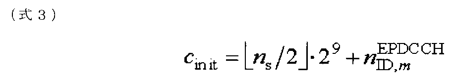
ここで、NID,m
EPDCCHは、上記USIDと等しい。なお、nsは、無線フレーム内のスロット番号である。また、mは、EPDCCHセット番号である。
また、スモール基地局SeNBは、上記USIDに基づいて疑似ランダム系列(スクランブル系列)C(i)を初期化し、初期化された疑似ランダム系列に基づいてEPDCCHに関連づけられるDM-RSを生成(スクランブル)してもよい。例えば、疑似ランダム系列C(i)は、(式4)を用いて初期化されてもよい。
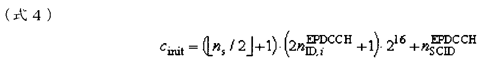
ここで、NID,i
EPDCCHは、上記USIDと等しい。なお、nsは、無線フレーム内のスロット番号である。また、NID,i
EPDCCHは、例えば、2である。
また、スモール基地局SeNBは、ステップS101でユーザ端末UEに通知されるUSIDに基づいて疑似ランダム系列(スクランブル系列)C(i)を初期化し、初期化された疑似ランダム系列に基づいてPDSCHに関連づけられるDM-RSを生成(スクランブル)してもよい。例えば、疑似ランダム系列C(i)は、(式5)を用いて初期化されてもよい。

ここで、NID
(i)は、上記USIDと等しい。なお、nsは、無線フレーム内のスロット番号である。また、NSCIDは、0又は1が設定される。
スモール基地局SeNBは、以上のように生成される下り信号を、ユーザ端末UEに送信する(ステップS103)。ユーザ端末UEは、マクロ基地局MeNBから通知されるUSIDを用いて下り信号の受信処理(デスクランブル)を行う。なお、USIDを用いて生成される下り信号は、上述のCSI-RS、EPDCCHによる送信信号、EPDCCH用のDM-RS、PDSCH用のDM-RSに限られない。例えば、PDSCHによる送信信号、スモールセルSの検出用信号(ディスカバリー信号)の生成に、USIDが用いられてもよい。
ユーザ端末UEは、マクロ基地局MeNBから通知されるUSIDを用いて、上り信号を生成する(ステップS104)。
具体的には、ユーザ端末UEは、上記USIDに基づいて疑似ランダム系列(スクランブル系列)C(i)を初期化し、初期化された疑似ランダム系列に基づいてPUSCH用のDM-RSを生成(スクランブル)してもよい。例えば、疑似ランダム系列C(i)は、(式6)を用いて初期化されてもよい。

ここで、NID,
csh_DMRSは、上記USIDと等しい。
また、ユーザ端末UEは、ステップS101でマクロ基地局MeNBから通知されるUSIDに基づいて擬似ランダム系列(スクランブル系列)C(i)を初期化し、初期化された擬似ランダム系列に基づいて、PUSCH又はPUCCH用のDM-RSやPUCCHによる送信信号などにグループホッピングを適用してもよい。例えば、擬似ランダム系列C(i)は、(式7)を用いて初期化されてもよい。

ここで、NID,
RSは、ステップS101でマクロ基地局MeNBから通知されるUSIDと等しい。
ユーザ端末UEは、以上のように生成される上り信号を、スモール基地局SeNBに送信する(ステップS105)。スモール基地局SeNBは、上述のUSIDを用いて上り信号の受信処理(デスクランブル)を行う。なお、USIDを用いて生成される上り信号は、上述のDM-RSやPUCCHによる送信信号に限られない。例えば、SRSやPUSCHやPRACHによる送信信号の生成に、USIDが用いられてもよい。
第1通知例によれば、第1USIDと第2USIDとに基づいて構成されるUSIDが、リリース11のUSID(第1USIDのみに基づいて構成されるUSID)と同様に、マクロ基地局MeNBから通知される。このため、USIDの拡張のための実装負荷を軽減しながら、スモールセルS間の干渉を十分にランダム化することができる。
(第2通知例)
図5は、USIDの第2通知例を示すシーケンス図である。第2通知例では、第1USIDと第2USIDとに基づいて構成されるUSID(図3参照)が、スモール基地局SeNB(Sセル)からユーザ端末UEに通知される。
図5は、USIDの第2通知例を示すシーケンス図である。第2通知例では、第1USIDと第2USIDとに基づいて構成されるUSID(図3参照)が、スモール基地局SeNB(Sセル)からユーザ端末UEに通知される。
図5に示すように、スモール基地局SeNBは、ユーザ端末UEに対して、第1USIDと第2USIDとに基づいて構成されるUSIDを通知する(ステップS201)。具体的には、スモール基地局SeNBは、RRCシグナリングなどの上位レイヤシグナリングを用いて、ユーザ端末UEに個別に、USIDを通知してもよい。
或いは、スモール基地局SeNBは、スモールセルSの検出用信号(ディスカバリー信号)の信号系列に括り付けて(リンクさせて)、USIDを通知してもよい。なお、USIDは、マクロ基地局MeNBからスモール基地局SeNBに通知されてもよいし、予めスモール基地局SeNBに記憶されていてもよい。
スモール基地局SeNBは、ステップS201でユーザ端末UEに通知されるUSIDを用いて、下り信号を生成する(ステップS202)。なお、ステップS202の詳細及びS203は、図4のステップS102及びS103と同様であるため、説明を省略する。
ユーザ端末UEは、スモール基地局SeNBから通知されるUSIDを用いて、上り信号を生成する(ステップS204)。なお、ステップS204の詳細及びS205は、図4のステップS104及びS105と同様であるため、説明を省略する。
第2通知例によれば、第1USIDと第2USIDとに基づいて構成されるUSIDが、スモール基地局SeNBから通知される。このため、ユーザ端末UEは、マクロ基地局MeNBに接続せずとも、USIDを取得できる。この結果、スモールセルS間でハンドオーバを行う際の処理負荷を軽減しながら、スモールセルS間の干渉を十分にランダム化することができる。
なお、第1及び第2通知例(図4、5)は、リリース11のUSID(第1USIDのみに基づいて構成されるUSID)を用いる場合にも適用可能である。具体的には、図4のステップS101、図5のステップS201において、スモール基地局SeNBは、ユーザ端末UEに対して、リリース11のUSIDを通知してもよい。
(第3通知例)
図6は、USIDの第3通知例を示すシーケンス図である。第3通知例では、第1USIDは、マクロ基地局MeNB(Pセル)からユーザ端末UEに通知され、第2USIDは、スモール基地局SeNB(Sセル)から送信される検出用信号(ディスカバリー信号)に関連づけられる。
図6は、USIDの第3通知例を示すシーケンス図である。第3通知例では、第1USIDは、マクロ基地局MeNB(Pセル)からユーザ端末UEに通知され、第2USIDは、スモール基地局SeNB(Sセル)から送信される検出用信号(ディスカバリー信号)に関連づけられる。
ここで、検出用信号はスモール基地局SeNBの消費電力を抑えるため、比較的長周期(例えば数百msec以上)で送信されてもよい。また、ユーザ端末UEについても消費電力を抑えるため、検出用信号を比較的長周期(例えば数秒以上)に受信してもよい。これによって、例えば基地局が消費電力を抑えるための間欠送信モード(Dormant mode)であっても、ユーザ端末が間欠受信モード(図17に示すようなIdle modeやDRX modeなど)であっても、検出用信号の受信が可能となる。
図17を参照し、検出用信号の受信例を説明する。図17において、Idle mode(又はIdle-like mode)(スモール基地局SeNB(スモールセルS)に接続していない状態)のユーザ端末UEは、active modeに移行する際に、検出用信号を受信して、スモール基地局SeNB(スモールセルS)を検出する(ケース1)。ケース1において、ユーザ端末UEは、スモール基地局SeNBからの検出用信号の受信品質を測定し、測定結果を含む測定報告(measurement report)をマクロ基地局MeNBに送信する。これにより、検出したスモール基地局SeNB(スモールセルS)が、Sセルとして割り当てられる。
また、active mode(スモール基地局SeNB(スモールセルS)に接続しており、データトラヒックを有する状態)のユーザ端末UEは、所定周期で、検出用信号を受信する(ケース2)。また、DRX mode(スモール基地局SeNB(スモールセルS)に接続しており、データトラヒックを有しない状態)のユーザ端末UEは、例えば、active modeよりも長い周期で、検出用信号を受信する(ケース3)。ケース3において、スモール基地局SeNBは、間欠送信モード(Dormant mode)に移行してもよい。
また、Idle mode(又はIdle-like mode)(スモール基地局SeNB(スモールセルS)に接続していない状態、特に、D2D(Device to Device)通信を行う場合)のユーザ端末UEは、例えば、active modeよりも長い周期で、検出用信号を受信する(ケース4)。第3通知例では、ケース1-4などでユーザ端末UEに受信される検出用信号に、上述の第2USIDが関連づけられていてもよい。
図6を参照し、第3通知例のシーケンスを詳述する。図6に示すように、マクロ基地局MeNBは、ユーザ端末UEに対して、第1USIDを通知する(ステップS301)。具体的には、マクロ基地局MeNBは、RRCシグナリングなどの上位レイヤシグナリングを用いて、ユーザ端末UEに個別に通知する。
スモール基地局SeNBは、ユーザ端末UEに対して、第2USIDを通知する(ステップS302)。具体的には、スモール基地局SeNBは、図17を参照して説明したように検出される検出用信号(ディスカバリー信号)の信号系列に括り付けて(リンクさせて)、第2USIDを通知してもよい。或いは、スモール基地局SeNBは、第2USIDを報知してもよい。
なお、第2USIDは、マクロ基地局MeNBからスモール基地局SeNBに通知されてもよいし、予めスモール基地局SeNBに記憶されていてもよい。また、第1USIDも、マクロ基地局MeNBからスモール基地局SeNBに通知されてもよいし、予めスモール基地局SeNBに記憶されていてもよい。
スモール基地局SeNBは、上記第1USID及び第2USIDに基づいてUSIDを演算し、演算されたUSIDを用いて下り信号を生成する(ステップS303)。例えば、スモール基地局SeNBは、図3に示すように、第1USID及び第2USIDを乗算して、USIDを生成する。なお、ステップS303における下り信号の生成の詳細は、図4のステップS102と同様であるため、説明を省略する。
スモール基地局SeNBは、生成された下り信号を、ユーザ端末UEに送信する(ステップS304)。ユーザ端末UEは、マクロ基地局MeNBから通知される第1USIDとスモール基地局SeNBから通知される第2USIDに基づいてUSIDを演算し、演算されたUSIDに基づいて下り信号の受信処理(デスクランブル)を行う。例えば、ユーザ端末UEは、図3に示すように、第1USID及び第2USIDを乗算して、USIDを生成する。
ユーザ端末UEは、第1USIDと第2USIDとに基づいて演算されたUSIDを用いて、上り信号を生成する(ステップS305)。なお、ステップS305における上り信号の生成の詳細は、図4のステップS104と同様であるため、説明を省略する。
ユーザ端末UEは、生成された上り信号を、スモール基地局SeNBに送信する(ステップS306)。スモール基地局SeNBは、上述のように演算されたUSIDに基づいて下り信号の受信処理(デスクランブル、デマッピング)を行う。
第3通知例によれば、第1USIDがマクロ基地局MeNBから通知される一方、第2USIDがスモール基地局SeNBから通知される。これにより、例えば、スモールセルS間でハンドオーバする際におけるマクロセルMからの制御信号量を削減することができる。
(第4通知例)
図7は、USIDの第4通知例を示すシーケンス図である。第4通知例では、第1USIDは、マクロ基地局MeNB(Pセル)からユーザ端末UEに通知され、第2USIDは、マクロセルMのセルID(セル識別子)に関連づけられる。
図7は、USIDの第4通知例を示すシーケンス図である。第4通知例では、第1USIDは、マクロ基地局MeNB(Pセル)からユーザ端末UEに通知され、第2USIDは、マクロセルMのセルID(セル識別子)に関連づけられる。
図7に示すように、マクロ基地局MeNBは、ユーザ端末UEにおけるセルIDの検出に用いられる同期信号(PSS:Primary Synchronization Signal、SSS:Secondary Synchronization Signal)を送信する(ステップS401)。ユーザ端末UEは、マクロ基地局MeNBから送信される同期信号に基づいて、セルIDを検出する。ユーザ端末UEは、セルIDに関連づけられる(括り付けられる、リンクされる)第2USIDを取得する。
また、マクロ基地局MeNBは、ユーザ端末UEに対して、第1USIDを通知する(ステップS402)。具体的には、マクロ基地局MeNBは、RRCシグナリングなどの上位レイヤシグナリングを用いて、ユーザ端末UEに個別に通知する。
なお、ステップS403-S406は、図6のステップS303-S306と同様であるため、説明を省略する。
第4通知例によれば、第2USIDがマクロセルMのセルIDに関連づけられるので、第2USIDを個別にユーザ端末UEに通知する必要がない。このため、USIDの通知に伴うシグナリング量を軽減できる。
(第2態様)
図8を参照し、本発明の第2態様に係る無線通信方法を説明する。第2態様に係る無線通信方法では、上記USIDを用いて生成されるCSI-RSが、ホッピングパターンに基づいてホッピングされる配置リソースにマッピングされる。なお、第2態様に係る無線通信方法において用いられるUSIDは、第1USIDと第2USIDとに基づいて構成されるUSIDであってもよいし、リリース11のUSIDであってもよい。
図8を参照し、本発明の第2態様に係る無線通信方法を説明する。第2態様に係る無線通信方法では、上記USIDを用いて生成されるCSI-RSが、ホッピングパターンに基づいてホッピングされる配置リソースにマッピングされる。なお、第2態様に係る無線通信方法において用いられるUSIDは、第1USIDと第2USIDとに基づいて構成されるUSIDであってもよいし、リリース11のUSIDであってもよい。
CSI-RSは、CSI-RS構成(CSI Reference Signal configuration)が示す配置リソース(例えば、リソースエレメント)に、所定周期(例えば、5サブフレーム周期)で配置される。ここで、CSI-RS構成は、周波数リソース(サブキャリアk)と時間リソース(OFDMシンボルl)のシフト量(k’,l’)を示す。当該シフト量に基づいて、CSI-RSの配置リソースが決定される。例えば、リリース11のノーマルCP(Cyclic Prefix)の場合、32種類のCSI-RS構成#0-#31が定められる。なお、CSI-RS構成は、「CSI-RS Config.」、「Config.」などと呼ばれもよい。
かかるCSI-RS構成は、準静的(semi-static)に設定(configure)され、RRCシグナリングなどの上位レイヤシグナリングでユーザ端末UEに通知される。このため、スモールセルS間でCSI-RSの配置リソースの衝突が一度発生すると、新たなCSI-RS構成が再設定(re-configure)されるまでは、当該衝突が発生し続けてしまうことになる。この結果、CSI-RSについて、スモールセルS間の干渉のランダム化効果を十分に得ることができない恐れがある。
そこで、第2態様に係る無線通信方法では、CSI-RS構成をホッピングパターンに従ってホッピングさせることで、スモールセルS間でのCSI-RSの配置リソースの衝突を防止する。この結果、CSI-RSについて、スモールセルS間の干渉のランダム化効果を向上させることができる。
(CSI-RS構成のホッピングパターン)
図8は、CSI-RS構成のホッピングパターンを示す図である。図8では、CSI-RS構成(CSI-RS Config)#1が、上位レイヤシグナリングにより、ユーザ端末UEに通知(configure)されるものとする。なお、図8では、5サブフレーム周期でCSI-RSが配置されるものとするが、これに限られない。
図8は、CSI-RS構成のホッピングパターンを示す図である。図8では、CSI-RS構成(CSI-RS Config)#1が、上位レイヤシグナリングにより、ユーザ端末UEに通知(configure)されるものとする。なお、図8では、5サブフレーム周期でCSI-RSが配置されるものとするが、これに限られない。
図8に示すように、CSI-RS構成は、ホッピングパターンに従って、ホッピングされる。ここで、ホッピングパターンとは、時間に基づく関数によって定められるCSI-RS構成の組み合わせである。例えば、図8において、サブフレーム#0では、CSI-RS構成#1に基づいてCSI-RSが配置される。一方、サブフレーム#5では、CSI-RS構成#3に基づいてCSI-RSが配置される。また、サブフレーム#10では、CSI-RS構成#10に基づいてCSI-RSが配置される。このサブフレーム#0、#5、#10におけるCSI-RS構成の組み合わせ(#1、#3、#10)が、ホッピングパターンと呼ばれてもよい。
また、図8において、サブフレーム#0、#5、#10のそれぞれにおいて適用されるCSI-RS構成(Config.)は、(式8)により決定されてもよい。
(式8)
config.={Base_config.+h(t)} mod 32
ここで、Base_config.は、RRCシグナリングなどの上位レイヤシグナリングにより設定(configure)されるCSI-RS構成である。また、h(t)は、ホッピングパターンを示す関数であり、tは、時間(例えば、フレーム番号又はサブフレーム番号、図8では、サブフレーム番号)である。
(式8)
config.={Base_config.+h(t)} mod 32
ここで、Base_config.は、RRCシグナリングなどの上位レイヤシグナリングにより設定(configure)されるCSI-RS構成である。また、h(t)は、ホッピングパターンを示す関数であり、tは、時間(例えば、フレーム番号又はサブフレーム番号、図8では、サブフレーム番号)である。
(式8)では、同じホッピングパターンh(t)であっても、異なるBase_config.が割り当てられる場合、CSI-RSの配置リソースの衝突を回避できる。このため、スモールセルS間でCSI-RSを直交させることもできる。
また、図8において、ホッピングパターン(図8では、CSI-RS構成#1、#3、#10の組み合わせ)が適用される周期は、ホッピング周期とも呼ばれる。かかるホッピング周期は、サブフレーム(10msec)単位であってもよいし、無線フレーム(100msec)単位であってもよい。例えば、図8のホッピング周期は、5サブフレーム×3=15サブフレームである。
また、スモールセルS(Sセル)においてNCTが適用される場合、マクロセルM(Pセル)でフレーム同期が確立されている。このため、ホッピング周期は、例えば、1024msecなど、比較的長い周期とすることが可能である。ホッピング周期を長くすることで、ホッピング周期内におけるCSI-RS構成の組み合わせが増加するので、ホッピングパターン数を増加させることができる。この結果、スモールセルS間の干渉のランダム化効果を更に向上させることができる。
なお、以上のようにホッピングされるCSI-RS構成は、Zero-Powerであってもよいし、Non-zero-powerであってもよい。Zero-powerのCSI-RS構成とは、CSI-RSを送信しないようにするリソースの位置を示すものである。一方、Non-Zero-powerのCSI-RS構成とは、CSI-RSを送信しないようにするリソースの位置を示すものである。Zero-power/Non-Zero-powerのCSI-RS構成を所定周期でホッピングすることで、干渉推定用リソースをランダム化することができる。
(CSI-RS構成のホッピングパターンの通知例)
次に、CSI-RS構成のホッピングパターンの通知例を説明する。なお、以下において、CSI-RS構成のホッピングパターンは、マクロ基地局MeNB(Pセル)又はスモール基地局SeNB(Sセル)のいずれからユーザ端末UEに通知されてもよい。
次に、CSI-RS構成のホッピングパターンの通知例を説明する。なお、以下において、CSI-RS構成のホッピングパターンは、マクロ基地局MeNB(Pセル)又はスモール基地局SeNB(Sセル)のいずれからユーザ端末UEに通知されてもよい。
具体的には、CSI-RS構成のホッピングパターン(例えば、上述のh(t))は、RRCシグナリングなどの上位レイヤシグナリングにより、ユーザ端末UEに通知されてもよい。上記(式8)では、32種類の「Base_config.」が存在する。このため、ホッピングパターンの総数は、32×h(t)用に確保されるビット数と等しくなる。
また、CSI-RS構成のホッピングパターンは、USIDに関連づけられてもよい(リンクさせてもよい)。また、第1USIDと第2USIDとに基づいて構成されるUSIDが用いられる場合、CSI-RS構成のホッピングパターンは、第2USIDに関連づけられてもよい。かかる場合、USIDとは別にホッピングパターンを通知する必要がなく、シグナリング量を低減できる。
また、第2態様に係る無線通信方法において、CSI-RS構成のホッピングを適用するか否か(ON/OFF)は、切り替え可能に構成されてもよい。具体的には、CSI-RS構成のホッピングを適用するか否かは、CSI-RS構成のホッピングパターンh(t)の値に関連づけてユーザ端末UEに通知(configure)されてもよい。例えば、上述のh(t)が特定の値(例えば、「0」)である場合、CSI-RS構成のホッピングが適用されないこと(OFF)を示してもよい。また、特定の値以外(例えば、「1」以上)である場合、CSI-RS構成のホッピングが適用されること(「ON」)を示してもよい。
また、CSI-RS構成のホッピングを適用するか否かは、第2USIDの値によって、ユーザ端末UEに通知されてもよい。また、CSI-RS構成のホッピングを適用するか否かは、第2USIDに基づいてUSIDが構成されるか否かによって、ユーザ端末UEに通知されてもよい。例えば、第2USIDに基づいてUSIDが構成される場合、CSI-RS構成のホッピングが適用されることを示してもよい。
また、CSI-RS構成のホッピングを適用するか否かは、独立のビットを用いて、ユーザ端末UEに通知されてもよい。例えば、1ビットを用いる場合、「0」がCSI-RS構成のホッピングが適用されないこと(OFF)を示し、「1」がCSI-RS構成のホッピングが適用されること(ON)を示してもよい。
第2態様に係る無線通信方法によれば、CSI-RS構成をホッピングさせることで、CSI-RS構成を再設定(reconfigure)する場合と比較して、CSI-RSの配置リースを簡易及び短周期で変更できる。この結果、CSI-RSについて、スモールセルS間の干渉のランダム化効果を向上させることができる。
(第3態様)
図9及び10を参照し、本発明の第3態様に係る無線通信方法を説明する。第3態様に係る無線通信方法では、上記USIDを用いて生成されるEPDCCHの送信信号が、ホッピングパターンに基づいてホッピングされる配置リソース(以下、EPDCCHリソースという)にマッピングされる。なお、第3態様に係る無線通信方法において用いられるUSIDは、第1USIDと第2USIDとに基づいて構成されるUSIDであってもよいし、リリース11のUSIDであってもよい。
図9及び10を参照し、本発明の第3態様に係る無線通信方法を説明する。第3態様に係る無線通信方法では、上記USIDを用いて生成されるEPDCCHの送信信号が、ホッピングパターンに基づいてホッピングされる配置リソース(以下、EPDCCHリソースという)にマッピングされる。なお、第3態様に係る無線通信方法において用いられるUSIDは、第1USIDと第2USIDとに基づいて構成されるUSIDであってもよいし、リリース11のUSIDであってもよい。
図9は、EPDCCHリソースの説明図である。図9に示すように、EPDCCHリソースは、システム帯域幅に分散された所定数の物理リソースブロック(PRB)(又は、PRBペア、以下、単にPRBという)で構成される。かかるPRBは、PRBインデックスにより識別される。
下り制御情報(DCI)は、局所マッピング(Localized Mapping)又は分散マッピング(Distributed Mapping)でEPDCCHリソースにマッピングされ、送信される。図9Aに示すように、局所マッピングでは、1DCIが、EPDCCHリソースを構成する特定のPRB(例えば、チャネル品質が最も良いPRB)に局所的にマッピングされる。局所マッピングでは、チャネル品質(CQI)に基づくため、周波数スケジューリングゲインを得ることができる。
一方、図9Bに示すように、分散マッピングでは、1DCIが、EPDCCHリソースを構成する複数のPRBに分散してマッピングされる。分散マッピングでは、1DCIが周波数方向に分散して配置されるので、周波数ダイバーシチゲインを得ることができる。
以上のようなEPDCCHリソースは、準静的(semi-static)に設定(configure)されるか、あるいは、固定的に予め定められる。このため、スモールセルS間でEPDCCHリソースの衝突が一度発生すると、当該衝突が発生し続けてしまうことになる。この結果、EPDCCHについて、スモールセルS間の干渉のランダム化効果を十分に得られない恐れがある。
そこで、第3態様に係る無線通信方法では、EPDCCHリソースをホッピングパターンに従ってホッピングさせることで、スモールセルS間でのEPDCCHリソースの衝突を防止する。この結果、EPDCCHについて、スモールセルS間の干渉のランダム化効果を向上させることができる。
(EPDCCHリソースのホッピングパターン)
図10は、EPDCCHリソースのホッピングパターンの説明図である。図10では、EPDCCHリソースを構成するPRBのPRBインデックスが、RRCシグナリングなどの上位レイヤシグナリングにより、ユーザ端末UEに通知(configure)されるものとする。
図10は、EPDCCHリソースのホッピングパターンの説明図である。図10では、EPDCCHリソースを構成するPRBのPRBインデックスが、RRCシグナリングなどの上位レイヤシグナリングにより、ユーザ端末UEに通知(configure)されるものとする。
図10に示すように、EPDCCHリソースは、ホッピングパターンに従って、周波数方向にホッピングされる(シフトされる)。ここで、ホッピングパターンとは、時間に基づく関数によって定められるホッピング量(例えば、シフトされるPRB数、又は無線フレーム数)の組み合わせである。
例えば、図10において、時刻t+aのEPDCCHリソースは、時刻tのEPDCCHリソースから周波数方向に、2PRBシフトされる。また、時刻t+bのEPDCCHリソースは、時刻t+aのEPDCCHリソースから周波数方向に、3PRBシフトされる。この時刻t、t+a、t+bにおけるホッピング量(ここでは、PRB数)の組み合わせ(0、2、3)が、ホッピングパターンと呼ばれてもよい。なお、図10の変数a及びbの値は、等しく設定されてもよいし、等しくなくともよい。
また、図10の時刻t+a、t+bでは、それぞれ、2PRB、5(2+3)PRBがシステム帯域からはみ出す。このため、システム帯域幅からはみ出したPRBは、巡回シフトされ、システム帯域内に戻される。
また、図10において、ホッピングパターンが適用される周期は、ホッピング周期とも呼ばれる。かかるホッピング周期は、サブフレーム(10msec)単位であってもよいし、無線フレーム(100msec)単位であってもよい。
また、スモールセルS(Sセル)においてNCTが適用される場合、マクロセルM(Pセル)でフレーム同期が確立されている。このため、ホッピング周期は、例えば、1024msecなど、比較的長い周期とすることが可能である。ホッピング周期を長くすることで、ホッピング周期内におけるホッピング量の組み合わせが増加するので、ホッピングパターン数を増加させることができる。この結果、スモールセルS間の干渉のランダム化効果を更に向上させることができる。
(EPDCCHリソースのホッピングパターンの通知例)
次に、EPDCCHリソースのホッピングパターンの通知例を説明する。なお、以下において、EPDCCHリソースのホッピングパターンは、マクロ基地局MeNB(Pセル)又はスモール基地局SeNB(Sセル)のいずれからユーザ端末UEに通知されてもよい。
次に、EPDCCHリソースのホッピングパターンの通知例を説明する。なお、以下において、EPDCCHリソースのホッピングパターンは、マクロ基地局MeNB(Pセル)又はスモール基地局SeNB(Sセル)のいずれからユーザ端末UEに通知されてもよい。
具体的には、EPDCCHリソースのホッピングパターンは、RRCシグナリングなどの上位レイヤシグナリングにより、ユーザ端末UEに通知されてもよい。
また、EPDCCHリソースのホッピングパターンは、USIDに関連づけられてもよい(リンクさせてもよい)。また、第1USIDと第2USIDとに基づいて構成されるUSIDが用いられる場合、EPDCCHリソースのホッピングパターンは、第2USIDに関連づけられてもよい。かかる場合、USIDとは別にホッピングパターンを通知する必要がなく、シグナリング量を低減できる。
また、第3態様に係る無線通信方法において、EPDCCHリソースのホッピングを適用するか否か(ON/OFF)は、切り替え可能に構成されてもよい。具体的には、EPDCCHリソースのホッピングを適用するか否かは、EPDCCHリソースのホッピングパターンの値に関連づけてユーザ端末UEに通知(configure)されてもよい。
また、EPDCCHリソースのホッピングを適用するか否かは、第2USIDの値によって、ユーザ端末UEに通知されてもよい。また、EPDCCHリソースのホッピングを適用するか否かは、第2USIDに基づいてUSIDが構成されるか否かによって、ユーザ端末UEに通知されてもよい。例えば、第2USIDに基づいてUSIDが構成される場合、EPDCCHリソースのホッピングが適用されることを示してもよい。
また、EPDCCHリソースのホッピングを適用するか否かは、独立のビットを用いて、ユーザ端末UEに通知されてもよい。例えば、1ビットを用いる場合、「0」がEPDCCHリソースのホッピングが適用されないこと(OFF)を示し、「1」がEPDCCHリソースのホッピングが適用されること(ON)を示してもよい。
第3態様に係る無線通信方法によれば、EPDCCHリソースをホッピングさせることで、EPDCCHリソースを簡易及び短周期で変更できる。この結果、EPDCCHについて、スモールセルS間の干渉のランダム化効果を向上させることができる。
(無線通信システムの構成)
以下、本実施の形態に係る無線通信システムについて、詳細に説明する。この無線通信システムでは、第1-第3態様に係る無線通信方法が適用される。
以下、本実施の形態に係る無線通信システムについて、詳細に説明する。この無線通信システムでは、第1-第3態様に係る無線通信方法が適用される。
図11は、本実施の形態に係る無線通信システムの概略構成図である。図11に示すように、無線通信システム1は、マクロセルC1を形成するマクロ基地局11と、マクロセルC1内に配置され、マクロセルC1よりも狭いスモールセルC2を形成するスモール基地局12a及び12bとを備えている。また、マクロセルC1及び各スモールセルC2には、ユーザ端末20が配置されている。なお、マクロセルC1(マクロ基地局11)、スモールセルC2(スモール基地局12)、ユーザ端末20の数は図11に示すものに限られない。
また、マクロセルC1及び各スモールセルC2には、ユーザ端末20が配置されている。ユーザ端末20は、マクロ基地局11及び/又はスモール基地局12と無線通信可能に構成されている。また、ユーザ端末20は、各スモールセルC2で用いられるコンポーネントキャリアを統合して(キャリアアグリゲーション)、複数のスモール基地局12と通信できる。或いは、ユーザ端末20は、マクロセルC1、スモールセルC2でそれぞれ用いられるコンポーネントキャリアを統合して、マクロ基地局11及びスモール基地局12と通信できる。
ユーザ端末20とマクロ基地局11との間は、相対的に低い周波数帯域(例えば、2GHz)のキャリアを用いて通信が行なわれる。一方、ユーザ端末20とスモール基地局12との間は、相対的に高い周波数帯域(例えば、3.5GHzなど)のキャリアが用いられるが、これに限られない。マクロ基地局11とスモール基地局12とで同一の周波数帯域が用いられてもよい。
また、マクロ基地局11と各スモール基地局12とは、X2インターフェースなどの相対的に低速(中遅延)の回線(Non-Ideal backhaul)で接続されてもよいし、光ファイバなどの相対的に高速(低遅延)の回線(Ideal backhaul)で接続されてもよいし、無線接続されてもよい。また、スモール基地局12間も、X2インターフェースなどの相対的に低速(中遅延)の回線(Non-Ideal backhaul)で接続されてもよいし、光ファイバなどの相対的に高速(低遅延)の回線(Ideal backhaul)で接続されてもよいし、無線接続されてもよい。
マクロ基地局11及び各スモール基地局12は、それぞれ上位局装置30に接続され、上位局装置30を介してコアネットワーク40に接続される。なお、上位局装置30には、例えば、アクセスゲートウェイ装置、無線ネットワークコントローラ(RNC)、モビリティマネジメントエンティティ(MME)等が含まれるが、これに限定されるものではない。
なお、マクロ基地局11は、相対的に広いカバレッジを有する無線基地局であり、eNodeB(eNB)、無線基地局、送信ポイント(transmission point)などと呼ばれてもよい。スモール基地局12は、局所的なカバレッジを有する無線基地局であり、RRH(Remote Radio Head)、ピコ基地局、フェムト基地局、Home eNodeB、送信ポイント、eNodeB(eNB)などと呼ばれてもよい。ユーザ端末20は、LTE、LTE-Aなどの各種通信方式に対応した端末であり、移動通信端末だけでなく固定通信端末を含んでよい。
また、無線通信システム1では、下りリンクの通信チャネルとして、各ユーザ端末20で共有される物理下り共有チャネル(PDSCH)と、物理下り制御チャネル(PDCCH)、拡張物理下り制御チャネル(EPDCCH)、PCFICH、PHICH、報知チャネル(PBCH)などが用いられる。PDSCHにより、ユーザデータや上位レイヤ制御情報が伝送される。PDCCH、EPDCCHにより、下り制御情報(DCI)が伝送される。
また、無線通信システム1では、上りリンクの通信チャネルとして、各ユーザ端末20で共有される各ユーザ端末20で共有される物理上り共有チャネル(PUSCH)と、物理上り制御チャネル(PUCCH)、物理ランダムアクセスチャネル(PRACH)などが用いられる。PUSCHにより、ユーザデータや上位レイヤ制御情報が伝送される。また、PUCCHにより、下りリンクの無線品質情報(CQI:Channel Quality Indicator)や、送達確認情報(ACK/NACK)等が伝送される。
また、無線通信システム1では、下りリンクの参照信号として、PDSCHに関連づけられる端末固有参照信号(UE-Specific Reference Signal、DM-RSともいう)や、EPDCCHに関連づけられる復調用参照信号(DM-RS)、チャネル状態測定用参照信号(CSI-RS)や、スモールセルC2の検出用信号(DS:Discovery Signal)などが用いられる。また、無線通信システム1では、下りリンクの同期信号として、プライマリ同期信号(PSS)や、セカンダリ同期信号(SSS)などが用いられる。
また、無線通信システム1では、上りリンクの参照信号として、PUSCH又はPUCCH用の復調用参照信号(DM-RS:Demodulation-Reference Signal)や、SRS(Sounding Reference Signal)などが用いられる。
また、無線通信システム1では、1サブフレームの先頭最大3OFDMシンボルにPDCCHが配置されないキャリアタイプ(NCT:New Carrier Type)が用いられてもよい。
以下、マクロ基地局11及びスモール基地局12を区別しない場合、無線基地局10と総称する。
図12は、本実施の形態に係る無線基地局10の全体構成図である。無線基地局10は、MIMO伝送のための複数の送受信アンテナ101と、アンプ部102と、送受信部103と、ベースバンド信号処理部104と、呼処理部105と、伝送路インターフェース106とを備えている。
下りリンクにより無線基地局10からユーザ端末20に送信されるユーザデータは、上位局装置30から伝送路インターフェース106を介してベースバンド信号処理部104に入力される。
ベースバンド信号処理部104では、PDCPレイヤの処理、ユーザデータの分割・結合、RLC(Radio Link Control)再送制御の送信処理などのRLCレイヤの送信処理、MAC(Medium Access Control)再送制御、例えば、HARQの送信処理、スケジューリング、伝送フォーマット選択、チャネル符号化、逆高速フーリエ変換(IFFT:Inverse Fast Fourier Transform)処理、プリコーディング処理が行われて各送受信部103に転送される。また、下り制御信号(参照信号、同期信号、報知信号などを含む)に関しても、チャネル符号化や逆高速フーリエ変換等の送信処理が行われて、各送受信部103に転送される。
各送受信部103は、ベースバンド信号処理部104からアンテナ毎にプリコーディングして出力された下り信号を無線周波数帯に変換する。アンプ部102は、周波数変換された無線周波数信号を増幅して送受信アンテナ101により送信する。
一方、上り信号については、各送受信アンテナ101で受信された無線周波数信号がそれぞれアンプ部102で増幅され、各送受信部103で周波数変換されてベースバンド信号に変換され、ベースバンド信号処理部104に入力される。
ベースバンド信号処理部104では、入力された上り信号に含まれるユーザデータに対して、FFT処理、IDFT処理、誤り訂正復号、MAC再送制御の受信処理、RLCレイヤ、PDCPレイヤの受信処理がなされ、伝送路インターフェース106を介して上位局装置30に転送される。呼処理部105は、通信チャネルの設定や解放等の呼処理や、無線基地局10の状態管理や、無線リソースの管理を行う。
図13は、本実施の形態に係るユーザ端末20の全体構成図である。ユーザ端末20は、MIMO伝送のための複数の送受信アンテナ201と、アンプ部202と、送受信部203と、ベースバンド信号処理部204と、アプリケーション部205とを備えている。
下り信号については、複数の送受信アンテナ201で受信された無線周波数信号がそれぞれアンプ部202で増幅され、送受信部203で周波数変換され、ベースバンド信号処理部204に入力される。ベースバンド信号処理部204では、FFT処理や、誤り訂正復号、再送制御の受信処理等がなされる。この下り信号に含まれるユーザデータは、アプリケーション部205に転送される。アプリケーション部205は、物理レイヤやMACレイヤより上位のレイヤに関する処理等を行う。また、下りリンクのデータの内、報知情報もアプリケーション部205に転送される。
一方、上りリンクのユーザデータについては、アプリケーション部205からベースバンド信号処理部204に入力される。ベースバンド信号処理部204では、再送制御(H-ARQ(Hybrid ARQ))の送信処理や、チャネル符号化、プリコーディング、DFT処理、IFFT処理等が行われて各送受信部203に転送される。送受信部203は、ベースバンド信号処理部204から出力されたベースバンド信号を無線周波数帯に変換する。その後、アンプ部202は、周波数変換された無線周波数信号を増幅して送受信アンテナ201により送信する。
次に、図14-図16を参照し、マクロ基地局11と、スモール基地局12と、ユーザ端末20との機能構成について詳述する。
図14は、本実施の形態に係るマクロ基地局11の機能構成図である。図14に示すように、マクロ基地局11は、PCI送信処理部111と、USID送信処理部112と、を具備する。なお、USIDの第2通知例(図5参照)においては、USID送信処理部112は省略されてもよい。また、以下の機能構成は、マクロ基地局11が有するベースバンド信号処理部104などによって構成される。
PCI送信処理部111は、マクロ基地局11のセルID(PCI)の送信処理(例えば、変調、符号化など)を行う。具体的には、PCI送信処理部111は、セルIDの検出に用いられる同期信号(PSS、SSS)を送信する。
USID送信処理部112は、USIDの送信処理(例えば、変調、符号化など)を行う。USIDは、第1USIDと第2USIDとを演算結果によって構成されてもよい(図3)。
具体的には、USID送信処理部112は、USIDを含む上位レイヤ制御情報(例えば、RRCレイヤ、MACレイヤ)を生成し、生成した上位レイヤ制御情報の送信処理を行う。或いは、USID送信処理部112は、USIDを含む報知情報を生成し、生成した報知情報の送信処理を行ってもよい。また、USID送信処理部112は、伝送路インターフェース106を介して、USIDをスモール基地局12に通知してもよい。
また、USID送信処理部112は、第2USIDを含まず第1USIDを含む上位レイヤ制御情報(例えば、RRCレイヤ、MACレイヤ)生成し、生成した上位レイヤ制御情報の送信処理を行ってもよい。また、USID送信処理部112は、伝送路インターフェース106を介して、第2USIDをスモール基地局12に通知してもよい。
また、USID取得部112は、スモールセルC2における送信モード及び/又はキャリアタイプなどによって、第1USIDと第2USIDとに基づいてUSIDを構成するか、あるいは、第2USIDに基づかず第1USIDに基づいてUSIDを構成するかを切り替えてもよい。
図15は、本実施の形態に係るスモール基地局12の機能構成図である。図15に示すように、スモール基地局12は、USID取得部121と、下り信号送信処理部122と、上り信号受信処理部123と、を具備する。なお、以下の機能構成は、スモール基地局12が有するベースバンド信号処理部104などによって構成される。
USID取得部121は、下り信号の送信処理/上り信号の受信処理に用いられるUSIDを取得する。具体的には、USID取得部121は、マクロ基地局11から伝送路インターフェース106を介してUSIDを取得してもよいし、記憶部(不図示)に予め記憶されるUSIDを取得してもよい。また、USID取得部121は、第1USIDと第2USIDとを演算してUSIDを取得してもよい。
下り信号送信処理部122は、USID取得部121で取得されたUSIDを用いて、下り信号の送信処理(例えば、スクランブル、マッピング、変調、符号化など)を行う。下り信号送信処理部122は、本発明の生成部(下り信号を生成)及びマッピング部(下り信号をリソースにマッピング)を構成する。
具体的には、下り信号送信処理部122は、USIDに基づいて疑似ランダム系列(スクランブル系列)を初期化し、初期化された疑似ランダム系列に基づいて下り信号を生成(スクランブル)してもよい(第1態様、図4のステップS102参照)。上述のように、下り信号は、例えば、CS-RS、EPDCCHの送信信号、EPDCCH用のDM-RS、PDSCH用のDM-RS、PDSCH用の送信信号などであるが、これらに限られない。
また、下り信号送信処理部122は、ホッピングパターンに基づいてホッピングされる配置リソースに、下り信号をマッピングしてもよい。具体的には、下り信号送信処理部122は、ホッピングパターンに従ってホッピングされる配置リソース(ホッピングされるCSI-RS構成が示す配置リソース)に、CSI-RSをマッピングしてもよい(第2態様、図8参照)。また、下り信号送信処理部122は、ホッピングパターンに従ってホッピングされる配置リソース(EPDCCHリソース)に、EPDCCHの送信信号をマッピングしてもよい(第3態様、図10参照)。
なお、ホッピングパターンは、時間に基づく関数によって定められてもよい。また、ホッピング周期は、サブフレーム(10msec)単位であってもよいし、無線フレーム(100msec)単位であってもよい。スモール基地局12においてNCTが適用される場合、ホッピング周期は、例えば、1024msecなど、比較的長い周期に設定可能である。
上り信号受信処理部123は、USID取得部121で取得されたUSIDを用いて、上り信号の受信処理(例えば、デスクランブル、デマッピング、復調、復号化など)を行う。
具体的には、上り信号受信処理部123は、USIDに基づいて疑似ランダム系列(スクランブル系列)を初期化し、初期化された疑似ランダム系列に基づいて上り信号の受信処理(デスクランブル)を行う(第1態様、図4のステップS105参照)。上述のように、上り信号は、例えば、PUSCH又はPUCCH用のDM-RS、PUSCHの送信信号、PUCCHの送信信号、SRSなどであるが、これらに限られない。
図16は、本実施の形態に係るユーザ端末20の機能構成図である。図16に示すように、ユーザ端末20は、USID取得部211と、下り信号受信処理部212と、上り信号送信処理部213と、を具備する。なお、以下の機能構成は、ユーザ端末20が有するベースバンド信号処理部204などによって構成される。
USID取得部211は、下り信号の受信処理/上り信号の送信処理に用いられるUSIDを取得する。具体的には、USID取得部211は、マクロ基地局11又はスモール基地局12から、USIDを含む上位レイヤ制御情報(例えば、RRCレイヤ、MACレイヤ)又は報知情報を取得する。
また、USID取得部211は、マクロ基地局11から送信された、第1USIDを含む上位レイヤ制御情報又は報知情報を取得する一方、スモール基地局12から送信された、第2USIDを含む上位レイヤ制御情報又は報知情報を取得してもよい。
また、USID取得部211は、スモールセルC2の検出用信号(ディスカバリー信号)に関連づけられる第2USIDを取得してもよい。ここで、ユーザ端末20は、間欠受信モード(例えば、Idle modeやDRX modeなど)や、active modeなどにおいても、検出用信号を受信できる(例えば、図17のケース1~ケース4参照)。また、間欠受信モードのユーザ端末20は、active modeよりも長い周期で検出用信号を受信してもよい。
また、USID取得部211は、マクロセルC2のセルIDに関連づけられる第2USIDを取得してもよい。マクロセルC1のセルIDは、マクロ基地局11からの同期信号(PSS、SSS)に基づいて検出されてもよい。なお、スモールセルC2の検出用信号やマクロセルC1のセルIDに第2USIDが関連づけられる場合、第2USIDのシグナリングを省略できるので、シグナリング量の削減に有効である。
また、USID取得部211は、スモールセルC2における送信モード及び/又はキャリアタイプなどによって、第1USIDと第2USIDとに基づいて構成されるUSIDを取得するか、あるいは、第2USIDを取得せずに第1USID(リリース11のUSID)を取得するかを切り替えてもよい。
下り信号受信処理部212は、USID取得部211で取得されたUSIDを用いて、下り信号の受信処理(例えば、デスクランブル、デマッピング、復調、復号化など)を行う。
具体的には、下り信号受信処理部212は、USIDに基づいて疑似ランダム系列(スクランブル系列)を初期化し、初期化された疑似ランダム系列に基づいて下り信号の受信処理(デスクランブル)を行う(第1態様、図4のステップS103参照)。
また、下り信号受信処理部212は、ホッピングパターンに従ってホッピングされた配置リソースにマッピングされた下り信号をデマッピングしてもよい。なお、ホッピングパターンは、マクロ基地局11又はスモール基地局12から、RRCシグナリングなどの上位レイヤシグナリングにより通知されてもよい。或いは、ホッピングパターンは、USID取得部211で取得されるUSIDに関連づけられてもよい。また、ホッピングパターンが関連づけられるUSIDは、第1USIDと第2USIDとで構成されるUSIDであってもよいし、第2USIDであってもよい。
上り信号送信処理部213は、USID取得部211で取得されたUSIDを用いて、上り信号の送信処理(例えば、スクランブル、ホッピング、無線リソースへのマッピング、変調、符号化など)を行う。上り信号送信処理部213は、本発明の生成部(上り信号を生成)及びマッピング部(上り信号をリソースにマッピング)を構成する。
具体的には、上り信号送信処理部213は、USIDに基づいて疑似ランダム系列(スクランブル系列)を初期化し、初期化された疑似ランダム系列に基づいて上り信号を生成(スクランブル)してもよい(第1態様、図4のステップS104参照)。
無線通信システム1では、スモールセルC2において、第1USIDと第2USIDとに基づいて構成されるUSIDを用いて下り/上り信号が生成される。このため、隣接スモールセルC2に位置するユーザ端末20間におけるUSIDの衝突を防止でき、スモールセルC2間の干渉を十分にランダム化できる。また、ホッピングパターンに従ってホッピングされる配置リソースに下り信号が配置されるので、スモールセルC2間の干渉のランダム化効果を向上させることができる。
以上、上述の実施形態を用いて本発明について詳細に説明したが、当業者にとっては、本発明が本明細書中に説明した実施形態に限定されるものではないということは明らかである。本発明は、特許請求の範囲の記載により定まる本発明の趣旨及び範囲を逸脱することなく修正及び変更態様として実施することができる。従って、本明細書の記載は、例示説明を目的とするものであり、本発明に対して何ら制限的な意味を有するものではない。
本出願は、2013年4月5日出願の特願2013-079296に基づく。この内容は、全てここに含めておく。
Claims (10)
- マクロセルと重複してスモールセルが配置される無線通信システムにおいて、前記スモールセルを形成する無線基地局であって、
第1端末固有識別子と第2端末固有識別子とに基づいて構成される端末固有識別子を用いて、下り信号を生成する生成部と、
ユーザ端末に対して、前記下り信号を送信する送信部と、
を具備することを特徴とする無線基地局。 - 前記端末固有識別子は、前記マクロセルを形成するマクロ基地局から前記ユーザ端末に対して通知されることを特徴とする請求項1に記載の無線基地局。
- 前記端末固有識別子は、前記無線基地局から前記ユーザ端末に対して通知される、又は前記無線基地局から送信される検出用信号に関連づけられることを特徴とする請求項1に記載の無線基地局。
- 前記第1端末固有識別子は、前記マクロセルを形成するマクロ基地局から前記ユーザ端末に対して通知され、
前記第2端末固有識別子は、前記無線基地局から送信される検出用信号に関連づけられることを特徴とする請求項1に記載の無線基地局。 - 前記第1端末固有識別子は、前記マクロセルを形成するマクロ基地局から前記ユーザ端末に対して通知され、
前記第2端末固有識別子は、前記マクロセルのセル識別子に関連づけられることを特徴とする請求項1に記載の無線基地局。 - 前記第1端末固有識別子と前記第2端末固有識別子とに基づいて前記端末固有識別子を構成するか否かは、前記スモールセルにおける送信モード及び/又はキャリアタイプによって、決定されることを特徴とする請求項1から請求項5のいずれかに記載の無線基地局。
- 前記下り信号は、チャネル状態測定用参照信号(CSI-RS)であり、
ホッピングパターンに基づいてホッピングされる配置リソースに、前記CSI-RSをマッピングするマッピング部を更に具備し、
前記ホッピングパターンは、時間に基づく関数によって定められることを特徴とする請求項1から請求項5のいずれかに記載の無線基地局。 - 前記下り信号は、拡張物理下り制御チャネル(EPDCCH)による送信信号であり、
ホッピングパターンに基づいてホッピングされる配置リソースに、前記送信信号をマッピングするマッピング部を更に具備し、
前記ホッピングパターンは、時間に基づく関数によって定められることを特徴とする請求項1から請求項5のいずれかに記載の無線基地局。 - マクロセルと重複してスモールセルが配置される無線通信システムにおいて用いられるユーザ端末であって、
第1端末固有識別子と第2端末固有識別子とに基づいて構成される端末固有識別子を用いて、上り信号を生成する生成部と、
前記スモールセルを形成するスモール基地局に対して、前記上り信号を送信する送信部と、
を具備することを特徴とするユーザ端末。 - マクロセルと重複してスモールセルが配置される無線通信システムにおいて用いられる無線通信方法であって、
前記スモールセルを形成するスモール基地局において、第1端末固有識別子と第2端末固有識別子とに基づいて構成される端末固有識別子を用いて、下り信号を生成する工程と、ユーザ端末に対して、前記下り信号を送信する工程と、
前記ユーザ端末において、前記端末固有識別子を用いて、上り信号を生成する工程と、前記スモール基地局に対して、前記上り信号を送信する工程と、
を有することを特徴とする無線通信方法。
Priority Applications (2)
| Application Number | Priority Date | Filing Date | Title |
|---|---|---|---|
| US14/782,445 US20160073389A1 (en) | 2013-04-05 | 2014-03-25 | Radio base station, user terminal and radio communication method |
| EP14779913.4A EP2983392A4 (en) | 2013-04-05 | 2014-03-25 | WIRELESS BASE STATION, USER DEVICE AND WIRELESS COMMUNICATION PROCESS |
Applications Claiming Priority (2)
| Application Number | Priority Date | Filing Date | Title |
|---|---|---|---|
| JP2013-079296 | 2013-04-05 | ||
| JP2013079296A JP6320683B2 (ja) | 2013-04-05 | 2013-04-05 | 無線基地局、ユーザ端末及び無線通信方法 |
Publications (1)
| Publication Number | Publication Date |
|---|---|
| WO2014162929A1 true WO2014162929A1 (ja) | 2014-10-09 |
Family
ID=51658227
Family Applications (1)
| Application Number | Title | Priority Date | Filing Date |
|---|---|---|---|
| PCT/JP2014/058346 WO2014162929A1 (ja) | 2013-04-05 | 2014-03-25 | 無線基地局、ユーザ端末及び無線通信方法 |
Country Status (4)
| Country | Link |
|---|---|
| US (1) | US20160073389A1 (ja) |
| EP (1) | EP2983392A4 (ja) |
| JP (1) | JP6320683B2 (ja) |
| WO (1) | WO2014162929A1 (ja) |
Families Citing this family (5)
| Publication number | Priority date | Publication date | Assignee | Title |
|---|---|---|---|---|
| JP2013219507A (ja) * | 2012-04-06 | 2013-10-24 | Ntt Docomo Inc | 無線通信方法、ローカルエリア基地局装置、移動端末装置及び無線通信システム |
| US10028083B2 (en) * | 2014-11-05 | 2018-07-17 | At&T Intellectual Property I, L.P. | Mobility management |
| US10321326B2 (en) | 2015-01-20 | 2019-06-11 | Huawei Technologies Co., Ltd. | Information transmission method, device, and system |
| WO2016121251A1 (ja) * | 2015-01-29 | 2016-08-04 | ソニー株式会社 | 装置及び方法 |
| US11019157B2 (en) | 2019-03-06 | 2021-05-25 | At&T Intellectual Property I, L.P. | Connectionless service and other services for devices using microservices in 5G or other next generation communication systems |
Citations (4)
| Publication number | Priority date | Publication date | Assignee | Title |
|---|---|---|---|---|
| WO2011140264A1 (en) * | 2010-05-04 | 2011-11-10 | Qualcomm Incorporated | Methods and apparatuses for using channel state information reference signals |
| WO2013002528A2 (ko) * | 2011-06-30 | 2013-01-03 | 엘지전자 주식회사 | 무선 통신 시스템에서 하향링크 제어 채널 할당 방법 및 장치 |
| JP2013500643A (ja) * | 2009-07-28 | 2013-01-07 | 電信科学技術研究院 | チャネル内容の変更通知、チャネル再検出の方法、システム及び装置 |
| WO2013015195A1 (ja) * | 2011-07-22 | 2013-01-31 | シャープ株式会社 | 端末、基地局、通信システムおよび通信方法 |
Family Cites Families (10)
| Publication number | Priority date | Publication date | Assignee | Title |
|---|---|---|---|---|
| EP2339883B1 (en) * | 2009-12-22 | 2013-03-20 | Telefonaktiebolaget L M Ericsson (Publ) | Method and arrangement for a terminal of a wireless communication network |
| CN102754458B (zh) * | 2010-02-12 | 2015-09-16 | 黑莓有限公司 | 操作无线通信网络中的用户设备的方法、操作无线通信网络中的基站的方法、用户设备和基站 |
| US8824383B2 (en) * | 2010-06-22 | 2014-09-02 | Telefonaktiebolaget L M Ericsson (Publ) | Downlink scheduling in heterogeneous networks |
| KR101840642B1 (ko) * | 2011-06-07 | 2018-03-21 | 한국전자통신연구원 | 분산 안테나 무선 통신 시스템 및 그 방법 |
| EP2721881A1 (en) * | 2011-06-17 | 2014-04-23 | Telefonaktiebolaget LM Ericsson (PUBL) | A wireless device, a network node and methods therein |
| US9503914B2 (en) * | 2012-01-31 | 2016-11-22 | Apple Inc. | Methods and apparatus for enhanced scrambling sequences |
| KR20140143741A (ko) * | 2012-03-05 | 2014-12-17 | 소니 주식회사 | 통신 제어 장치, 통신 제어 방법 및 기지국 |
| JP6191997B2 (ja) * | 2012-03-06 | 2017-09-06 | シャープ株式会社 | 移動局装置、基地局装置、通信方法、および集積回路 |
| US9143984B2 (en) * | 2012-04-13 | 2015-09-22 | Intel Corporation | Mapping of enhanced physical downlink control channels in a wireless communication network |
| US20140177558A1 (en) * | 2012-12-20 | 2014-06-26 | Futurewei Technologies, Inc. | System and Methods for Almost Blank Subframe (ABS) Density and Range Extension Optimization in Heterogeneous Networks |
-
2013
- 2013-04-05 JP JP2013079296A patent/JP6320683B2/ja active Active
-
2014
- 2014-03-25 US US14/782,445 patent/US20160073389A1/en not_active Abandoned
- 2014-03-25 EP EP14779913.4A patent/EP2983392A4/en not_active Withdrawn
- 2014-03-25 WO PCT/JP2014/058346 patent/WO2014162929A1/ja active Application Filing
Patent Citations (4)
| Publication number | Priority date | Publication date | Assignee | Title |
|---|---|---|---|---|
| JP2013500643A (ja) * | 2009-07-28 | 2013-01-07 | 電信科学技術研究院 | チャネル内容の変更通知、チャネル再検出の方法、システム及び装置 |
| WO2011140264A1 (en) * | 2010-05-04 | 2011-11-10 | Qualcomm Incorporated | Methods and apparatuses for using channel state information reference signals |
| WO2013002528A2 (ko) * | 2011-06-30 | 2013-01-03 | 엘지전자 주식회사 | 무선 통신 시스템에서 하향링크 제어 채널 할당 방법 및 장치 |
| WO2013015195A1 (ja) * | 2011-07-22 | 2013-01-31 | シャープ株式会社 | 端末、基地局、通信システムおよび通信方法 |
Non-Patent Citations (2)
| Title |
|---|
| "E-UTRA Further Advancements for E-UTRA Physical Layer Aspects", 3GPP TR 36.814 |
| See also references of EP2983392A4 |
Also Published As
| Publication number | Publication date |
|---|---|
| US20160073389A1 (en) | 2016-03-10 |
| EP2983392A4 (en) | 2016-10-19 |
| JP2014204306A (ja) | 2014-10-27 |
| EP2983392A1 (en) | 2016-02-10 |
| JP6320683B2 (ja) | 2018-05-09 |
Similar Documents
| Publication | Publication Date | Title |
|---|---|---|
| US9467271B2 (en) | Radio base station apparatus, mobile terminal apparatus and radio communication system | |
| US9609641B2 (en) | Radio communication method, radio communication system, radio base station and user terminal | |
| US9742534B2 (en) | Radio communication method, radio communication system, radio base station and user terminal | |
| US20150372851A1 (en) | Radio base station, user terminal and radio communication method | |
| EP3425978B1 (en) | User terminal, wireless base station and wireless communication method | |
| JP6325249B2 (ja) | ユーザ端末及び無線通信方法 | |
| US11088790B2 (en) | User terminal, radio base station, and radio communication method | |
| WO2014020997A1 (ja) | 通信システム、基地局装置、移動端末装置及び通信方法 | |
| WO2015119005A1 (ja) | ユーザ端末、無線基地局及び無線通信方法 | |
| JP6320683B2 (ja) | 無線基地局、ユーザ端末及び無線通信方法 | |
| US20150263832A1 (en) | Radio communication method, radio communication system, radio base station and user terminal | |
| EP2983431B1 (en) | User terminal, small base station, and communications method | |
| JP2017147769A (ja) | ユーザ端末、無線通信方法及び移動通信システム | |
| US20170230976A1 (en) | Radio base station, user terminal and radio communication method |
Legal Events
| Date | Code | Title | Description |
|---|---|---|---|
| 121 | Ep: the epo has been informed by wipo that ep was designated in this application |
Ref document number: 14779913 Country of ref document: EP Kind code of ref document: A1 |
|
| NENP | Non-entry into the national phase |
Ref country code: DE |
|
| WWE | Wipo information: entry into national phase |
Ref document number: 14782445 Country of ref document: US |
|
| WWE | Wipo information: entry into national phase |
Ref document number: 2014779913 Country of ref document: EP |