WO2014161784A1 - A washer/dryer comprising a lock - Google Patents
A washer/dryer comprising a lock Download PDFInfo
- Publication number
- WO2014161784A1 WO2014161784A1 PCT/EP2014/056301 EP2014056301W WO2014161784A1 WO 2014161784 A1 WO2014161784 A1 WO 2014161784A1 EP 2014056301 W EP2014056301 W EP 2014056301W WO 2014161784 A1 WO2014161784 A1 WO 2014161784A1
- Authority
- WO
- WIPO (PCT)
- Prior art keywords
- front wall
- hole
- washer
- dryer
- lock
- Prior art date
- Legal status (The legal status is an assumption and is not a legal conclusion. Google has not performed a legal analysis and makes no representation as to the accuracy of the status listed.)
- Ceased
Links
Images




Classifications
-
- D—TEXTILES; PAPER
- D06—TREATMENT OF TEXTILES OR THE LIKE; LAUNDERING; FLEXIBLE MATERIALS NOT OTHERWISE PROVIDED FOR
- D06F—LAUNDERING, DRYING, IRONING, PRESSING OR FOLDING TEXTILE ARTICLES
- D06F39/00—Details of washing machines not specific to a single type of machines covered by groups D06F9/00 - D06F27/00
- D06F39/12—Casings; Tubs
- D06F39/14—Doors or covers; Securing means therefor
-
- E—FIXED CONSTRUCTIONS
- E05—LOCKS; KEYS; WINDOW OR DOOR FITTINGS; SAFES
- E05B—LOCKS; ACCESSORIES THEREFOR; HANDCUFFS
- E05B9/00—Lock casings or latch-mechanism casings ; Fastening locks or fasteners or parts thereof to the wing
- E05B9/08—Fastening locks or fasteners or parts thereof, e.g. the casings of latch-bolt locks or cylinder locks to the wing
-
- E—FIXED CONSTRUCTIONS
- E05—LOCKS; KEYS; WINDOW OR DOOR FITTINGS; SAFES
- E05C—BOLTS OR FASTENING DEVICES FOR WINGS, SPECIALLY FOR DOORS OR WINDOWS
- E05C19/00—Other devices specially designed for securing wings, e.g. with suction cups
- E05C19/02—Automatic catches, i.e. released by pull or pressure on the wing
- E05C19/024—Automatic catches, i.e. released by pull or pressure on the wing with a bifurcated latch
-
- D—TEXTILES; PAPER
- D06—TREATMENT OF TEXTILES OR THE LIKE; LAUNDERING; FLEXIBLE MATERIALS NOT OTHERWISE PROVIDED FOR
- D06F—LAUNDERING, DRYING, IRONING, PRESSING OR FOLDING TEXTILE ARTICLES
- D06F37/00—Details specific to washing machines covered by groups D06F21/00 - D06F25/00
- D06F37/42—Safety arrangements, e.g. for stopping rotation of the receptacle upon opening of the casing door
-
- E—FIXED CONSTRUCTIONS
- E05—LOCKS; KEYS; WINDOW OR DOOR FITTINGS; SAFES
- E05B—LOCKS; ACCESSORIES THEREFOR; HANDCUFFS
- E05B63/00—Locks or fastenings with special structural characteristics
- E05B63/04—Locks or fastenings with special structural characteristics for alternative use on the right-hand or left-hand side of wings
Definitions
- the present invention relates to a washer/dryer that comprises a lock.
- the lid used for loading and unloading the laundry is enabled to be kept in the closed position by means of a lock.
- locking is realized by the placement of a tenon disposed on the lid into a lock disposed on the front wall of the body.
- the members that form the lock are in grouped state.
- the lock group is realized by passing the lock orifice into which the tenon enters entirely to the front side from the rear side of the front wall, through an opening disposed on the front wall and by fixing the lock orifice in this position.
- the opening direction of the washer/dryer lid is changed in accordance with the user preference.
- the positions of the hinge and the lock are changed. For this operation, the front wall of the washer/dryer is required to be removed, prolonging the labor time.
- the fixation process is generally performed by means of screws and this causes increase in terms of both the material cost and the labor cost.
- various embodiments are developed related to the mounting of the lock group to the front wall without screws.
- the opening arranged on the front wall should have the same dimensions as the lock orifice. Any change in the configuration of the orifice requires the front wall also to be changed.
- the aim of the present invention is the realization of a washer/dryer comprising a lock that can be easily mounted.
- the lock comprises a body that remains at the rear side of the front wall. On the body there is an extension that extends at least partially towards the front surface of the front wall through the hole on the front wall.
- the lock is enabled to be fixed to the front wall by means of a connection member that is seated over the extension situated at the front of the front wall and that is placed into the additional holes.
- connection member There is an orifice on the connection member, and on the extension a housing that aligns with the orifice when the connection member is mounted onto the extension.
- the tenon is inserted into the lock by passing through the orifice and the housing.
- the front wall comprises a first hole group having the hole and the additional holes and a second hole group that is symmetrical to the first hole group with respect to the center of the opening.
- the user can fix the lock to the first hole group or to the second hole group as desired.
- the washer/dryer comprises at least one claw housing arranged on the front wall and at least one claw that is disposed on the connection member and that is placed into the claw housing, thus enabling the connection member to be fixed to the front wall by the snap-fit method.
- the claw goes into claw housing and enables the connection member to be more firmly fixed to the front wall.
- the claw is flexible.
- the user can easily place the claw into the claw housing and easily remove the claw from the claw housing.
- the claw is situated on the connection member so as to be opposite to the protrusion.
- the protrusion placed into the additional hole stays in a position opposite to the claw placed into the claw housing.
- the connection member is enabled to be fixed to the front wall.
- the washer/dryer comprises a hinge having at least two feet that are placed into the first hole group or the second hole group.
- the protrusions on the connection member and the feet on the hinge are of similar lengths and/or aligned at the same levels.
- connection member is also wider than the hole and the extension so as to close the hole and the extension and hence to provide an aesthetic appearance at the side visible to the user.
- the lock in the washer/dryer is enabled to be easily mounted to the front wall.
- Figure 1 – is the perspective view of a washer/dryer.
- Figure 2 – is the front view of the front wall of a washer/dryer.
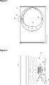
- Figure 3 – is the front view of a washer/dryer when the lock body is fixed to the front wall.
- Figure 4 – is the view of detail A in Figure 3.
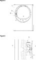
- Figure 5 — is the front view of a washer/dryer when the connection member is fixed to the front wall.
- Figure 6 — is the view of detail B in Figure 5.
- Figure 7 — is the front view of the connection member.
- Figure 8 — is the rear view of the connection member.
- Figure 9 – is the cross-sectional view of the connection member.
- Figure 10 — is the perspective view of the connection member while being mounted to the front wall.
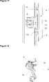
- Figure 11 – is the cross-sectional view of the lock while mounted to the front wall.
- Figure 12 — is the longitudinal cross-sectional view of the lock.
- Figure 13 — is the exploded view of the hinge and the front wall.
- Figure 14 — is the front view of a washer/dryer when the connection member and the hinge are fixed to the front wall.
- the washer/dryer (1) comprises
- the washer/dryer (1) of the present invention comprises
- the lock (6) When the lock (6) is fixed to the front wall (3) by means of the connection member (11), the front wall (3) remains between the body (9) and the connection member (11). Thus, the lock (6) is enabled to be easily mounted to the front wall (3) without using an additional fixing means such as screw, etc.
- connection member (11) comprises an orifice (13) that enables the tenon (7) to be placed into the lock (6) by passing therethrough.
- the extension (10) comprises a housing (14) that is aligned with the orifice (13) and that enables the tenon (7) to be placed into the lock (6) by passing therethrough.
- the washer/dryer (1) comprises at least two protrusions (15, 115) disposed on the connection member (11), at least two additional holes (12, 112) arranged on the front wall (3) and wherein the protrusions (15, 115) are placed, and the connection member (11) that is fixed to the front wall (3) by being slid after being placed into the additional holes (12, 112). With the connection member (11) being placed onto the front wall (3), the extension (10) remaining between the connection member (11) and the front wall (3) enables the body (9) to be fixed to the front wall (3).
- the lock (6) comprises a latch (22) that is pivotally connected to the body (9), that is disposed behind the housing (14), that is rotated by the tenon (7) by pushing while being placed into the lock (6), that enables the tenon (7) to be kept in the lock (6), and a spring (23) one end of which is mounted to the body (9) and the other end of which is mounted to the latch (22), that is compressed by the rotation of the latch (22) and that enables the latch (22) to resume its former position by transmitting the stored energy to the latch (22) when the latch (22) becomes free.
- the washer/dryer (1) comprises on the front wall (3) a first hole group (16) having the hole (8) and the additional holes (12, 112) and a second hole group (17) that is symmetrical to the first hole group (16) with respect to the center of the openining (4).
- the user can fix the lock (6) to the first hole group (16) or to the second hole group (17) as desired.
- the washer/dryer (1) comprises at least one claw housing (18, 118) arranged on the front wall (3) and at least one claw (19) that is disposed on the connection member (11) and that is placed into the claw housing (18, 118), thus enabling the connection member (11) to be fixed to the front wall (3) by the snap-fit method.
- the claw (19) goes into the claw housing (18, 118) and enables the connection member (11) to be more firmly fixed to the front wall (3).
- the claw (19) is flexible. Thus, the user can easily place the claw (19) into the claw housing (18, 118) and easily remove the claw (19) from the claw housing (18, 118).
- the protrusion (15, 115) is L-shaped.
- the connection member (11) fixed onto the front surface of the front wall (3) touches the rear surface of the front wall (3) by means of the L-shaped protrusions (15, 115), the connection member (11) is mounted to the front wall (3) and the lock (6) is enabled to be fixed.
- the claw (19) is disposed on the connection member (11) so as to be opposite to the protrusion (15, 115).
- the protrusion (15, 115) placed into the additional hole (12, 112) is in a position opposite to the claw (19) placed into the claw housing (18, 118).
- the connection member (11) is enabled to be fixed to the front wall (3).
- the washer/dryer (1) comprises a hinge (21) having at least two feet (20) that are placed into the first hole group (16) or the second hole group (17).
- the user can install the lock (6) instead of the hinge (21) or the hinge (21) instead of the lock (6).
- the hinge (21) and the lock (6) can be easily detached and replaced without removing the front wall (3) and the opening direction of the lid (5) can be changed in accordance with the user preference.
- connection member (11) is wider than the extension (10).
- the hole (8) and the extension (10) are prevented from being seen by the user and the visual look of the front wall (3) is improved.
- the lock (6) is enabled to be easily fixed to the front wall (3) without requiring an additional fixing member and the opening direction of the lid (5) is changed by easily replacing the lock (6) and the hinge (21).
Landscapes
- Engineering & Computer Science (AREA)
- Textile Engineering (AREA)
- Mechanical Engineering (AREA)
- Detail Structures Of Washing Machines And Dryers (AREA)
Abstract
The present invention relates to a washer/dryer (1) comprising two side walls (2) closing the volume from sides wherein the drum, in which the laundry is placed, and other machine elements are located, a front wall (3) closing the said volume from the front, an opening (4) that is arranged on the front wall (3) and enables the laundry to be placed in the drum, a lid (5) covering the opening (4), a hole (8) arranged on the front wall (3) around the opening (4), a lock (6) that is mounted to the front wall (3) and that has a body (9) remaining behind the hole (8) and an extension (10) bearing against the edge of the hole (8), and a tenon (7) that is disposed on the lid (5) and enables the lid (5) to remain in the closed position by being placed into the lock (6) after passing through the hole (8) when the lid (5) is closed.
Description
A WASHER/DRYER COMPRISING A LOCK
The present invention relates to a washer/dryer that comprises a lock.
In washers/dryers, the lid used for loading and unloading the laundry is enabled to be kept in the closed position by means of a lock. Generally, locking is realized by the placement of a tenon disposed on the lid into a lock disposed on the front wall of the body.
In the state of the art, the members that form the lock are in grouped state. The lock group is realized by passing the lock orifice into which the tenon enters entirely to the front side from the rear side of the front wall, through an opening disposed on the front wall and by fixing the lock orifice in this position. In some embodiments, the opening direction of the washer/dryer lid is changed in accordance with the user preference. In the state of the art, in order to change the opening direction of the lid, the positions of the hinge and the lock are changed. For this operation, the front wall of the washer/dryer is required to be removed, prolonging the labor time.
The fixation process is generally performed by means of screws and this causes increase in terms of both the material cost and the labor cost. In the state of the art, various embodiments are developed related to the mounting of the lock group to the front wall without screws.
In the state of the art embodiment, the European Patent Application No. EP1681386, a washer/dryer is explained, comprising a lock group which is mounted onto the front wall in a snap-fitting manner by being rotated and slid after being inserted from one side.
In these state of the art embodiments, the opening arranged on the front wall should have the same dimensions as the lock orifice. Any change in the configuration of the orifice requires the front wall also to be changed.
The aim of the present invention is the realization of a washer/dryer comprising a lock that can be easily mounted.
In the washer/dryer realized in order to attain the aim of the present invention and explicated in the claims, the lock comprises a body that remains at the rear side of the front wall. On the body there is an extension that extends at least partially towards the front surface of the front wall through the hole on the front wall. The lock is enabled to be fixed to the front wall by means of a connection member that is seated over the extension situated at the front of the front wall and that is placed into the additional holes. When the lock is mounted to the front wall, the body remains behind the front wall and the connection member in front thereof. Thus, the lock is enabled to be easily mounted to the front wall.
There is an orifice on the connection member, and on the extension a housing that aligns with the orifice when the connection member is mounted onto the extension. The tenon is inserted into the lock by passing through the orifice and the housing.
In an embodiment of the present invention, the front wall comprises a first hole group having the hole and the additional holes and a second hole group that is symmetrical to the first hole group with respect to the center of the opening. Thus, the user can fix the lock to the first hole group or to the second hole group as desired.
In an embodiment of the present invention, the washer/dryer comprises at least one claw housing arranged on the front wall and at least one claw that is disposed on the connection member and that is placed into the claw housing, thus enabling the connection member to be fixed to the front wall by the snap-fit method. When the protrusions disposed on the connection member are placed into the additional holes, the claw goes into claw housing and enables the connection member to be more firmly fixed to the front wall.
In an embodiment of the present invention, the claw is flexible. Thus, the user can easily place the claw into the claw housing and easily remove the claw from the claw housing.
In an embodiment of the present invention, the claw is situated on the connection member so as to be opposite to the protrusion. The protrusion placed into the additional hole stays in a position opposite to the claw placed into the claw housing. Thus, a portion of the front wall being between the protrusion and the claw, the connection member is enabled to be fixed to the front wall.
In an embodiment of the present invention, the washer/dryer comprises a hinge having at least two feet that are placed into the first hole group or the second hole group. The protrusions on the connection member and the feet on the hinge are of similar lengths and/or aligned at the same levels. Thus, the user can mount the lock instead of the hinge or the hinge instead of the lock. Thus, ease of assembly is provided.
In an embodiment of the present invention, the connection member is also wider than the hole and the extension so as to close the hole and the extension and hence to provide an aesthetic appearance at the side visible to the user.
By means of the present invention, the lock in the washer/dryer is enabled to be easily mounted to the front wall.
The model embodiments relating to the washer/dryer realized in order to attain the aim of the present invention are illustrated in the attached figures, where:
Figure 1 – is the perspective view of a washer/dryer.
Figure 2 – is the front view of the front wall of a washer/dryer.
Figure 3 – is the front view of a washer/dryer when the lock body is fixed to the front wall.
Figure 4 – is the view of detail A in Figure 3.
Figure 5 – is the front view of a washer/dryer when the connection member is fixed to the front wall.
Figure 6 – is the view of detail B in Figure 5.
Figure 7 – is the front view of the connection member.
Figure 8 – is the rear view of the connection member.
Figure 9 – is the cross-sectional view of the connection member.
Figure 10 – is the perspective view of the connection member while being mounted to the front wall.
Figure 11 – is the cross-sectional view of the lock while mounted to the front wall.
Figure 12 – is the longitudinal cross-sectional view of the lock.
Figure 13 – is the exploded view of the hinge and the front wall.
Figure 14 – is the front view of a washer/dryer when the connection member and the hinge are fixed to the front wall.
The elements illustrated in the figures are numbered as follows:
- Washer/dryer
- Side wall
- Front wall
- Opening
- Lid
- Lock
- Tenon
- Hole
- Body
- Extension
- Connection member
- , 112. Additional hole
- Orifice
- Housing
- 115 Protrusion
- First hole group
- Second hole group
- 118 Claw housing
- Claw
- Foot
- Hinge
- Latch
- Spring
The washer/dryer (1) comprises
- two side walls (2) closing the volume from sides wherein the drum, in which the laundry is placed, and other elements are located,
- a front wall (3) closing the said volume from the front,
- an opening (4) that is arranged on the front wall (3) and enables the laundry to be placed in the drum,
- a lid (5) closing the opening (4),
- a hole (8) arranged on the front wall (3) around the opening (4),
- a lock (6) that is mounted to the front wall (3) and that has a body (9) remaining behind the hole (8) and an extension (10) bearing against the edge of the hole (8), and
- a tenon (7) that is disposed on the lid (5) and enables the lid (5) to remain in the closed position by being placed into the lock (6) after passing through the hole (8) when the lid (5) is closed.
The washer/dryer (1) of the present invention comprises
- at least one additional hole (12, 112) that is arranged on the front wall (3) close to the hole (8), and
- a connection member (11) that has at least one protrusion (15, 115) placed into the additional hole (12, 112), that is mounted onto the front wall (3) by means of the protrusions (15, 115) and that enables the lock (6) to be fixed to the front wall (3) by being seated over the extension (10).
When the lock (6) is fixed to the front wall (3) by means of the connection member (11), the front wall (3) remains between the body (9) and the connection member (11). Thus, the lock (6) is enabled to be easily mounted to the front wall (3) without using an additional fixing means such as screw, etc.
The connection member (11) comprises an orifice (13) that enables the tenon (7) to be placed into the lock (6) by passing therethrough. The extension (10) comprises a housing (14) that is aligned with the orifice (13) and that enables the tenon (7) to be placed into the lock (6) by passing therethrough. Thus, when the connection member (11) is placed into the additional hole (12, 112), the tenon (7) is enabled to go into the lock (6) by passing through the orifice (13) and the housing (14). The washer/dryer (1) comprises at least two protrusions (15, 115) disposed on the connection member (11), at least two additional holes (12, 112) arranged on the front wall (3) and wherein the protrusions (15, 115) are placed, and the connection member (11) that is fixed to the front wall (3) by being slid after being placed into the additional holes (12, 112). With the connection member (11) being placed onto the front wall (3), the extension (10) remaining between the connection member (11) and the front wall (3) enables the body (9) to be fixed to the front wall (3). The lock (6) comprises a latch (22) that is pivotally connected to the body (9), that is disposed behind the housing (14), that is rotated by the tenon (7) by pushing while being placed into the lock (6), that enables the tenon (7) to be kept in the lock (6), and a spring (23) one end of which is mounted to the body (9) and the other end of which is mounted to the latch (22), that is compressed by the rotation of the latch (22) and that enables the latch (22) to resume its former position by transmitting the stored energy to the latch (22) when the latch (22) becomes free.
In an embodiment of the present invention, the washer/dryer (1) comprises on the front wall (3) a first hole group (16) having the hole (8) and the additional holes (12, 112) and a second hole group (17) that is symmetrical to the first hole group (16) with respect to the center of the openining (4). Thus, the user can fix the lock (6) to the first hole group (16) or to the second hole group (17) as desired.
In an embodiment of the present invention, the washer/dryer (1) comprises at least one claw housing (18, 118) arranged on the front wall (3) and at least one claw (19) that is disposed on the connection member (11) and that is placed into the claw housing (18, 118), thus enabling the connection member (11) to be fixed to the front wall (3) by the snap-fit method. When the protrusions (15, 115) disposed on the connection member (11) are placed into the additional holes (12, 112), the claw (19) goes into the claw housing (18, 118) and enables the connection member (11) to be more firmly fixed to the front wall (3).
In an embodiment of the present invention, the claw (19) is flexible. Thus, the user can easily place the claw (19) into the claw housing (18, 118) and easily remove the claw (19) from the claw housing (18, 118).
In an embodiment of the present invention, the protrusion (15, 115) is L-shaped. Thus, the connection member (11) fixed onto the front surface of the front wall (3) touches the rear surface of the front wall (3) by means of the L-shaped protrusions (15, 115), the connection member (11) is mounted to the front wall (3) and the lock (6) is enabled to be fixed.
In an embodiment of the present invention, the claw (19) is disposed on the connection member (11) so as to be opposite to the protrusion (15, 115). The protrusion (15, 115) placed into the additional hole (12, 112) is in a position opposite to the claw (19) placed into the claw housing (18, 118). Thus, by a portion of the front wall (3) being between the protrusion (15, 115) and the claw (19), the connection member (11) is enabled to be fixed to the front wall (3).
In an embodiment of the present invention, the washer/dryer (1) comprises a hinge (21) having at least two feet (20) that are placed into the first hole group (16) or the second hole group (17). Thus, the user can install the lock (6) instead of the hinge (21) or the hinge (21) instead of the lock (6). The hinge (21) and the lock (6) can be easily detached and replaced without removing the front wall (3) and the opening direction of the lid (5) can be changed in accordance with the user preference.
In an embodiment of the present invention, the connection member (11) is wider than the extension (10). Thus, the hole (8) and the extension (10) are prevented from being seen by the user and the visual look of the front wall (3) is improved.
By means of the present invention, the lock (6) is enabled to be easily fixed to the front wall (3) without requiring an additional fixing member and the opening direction of the lid (5) is changed by easily replacing the lock (6) and the hinge (21).
Claims (8)
- A washer/dryer (1) comprising- two side walls (2) closing the volume from sides wherein the drum, in which the laundry is placed, and other machine elements are located,- a front wall (3) closing the said volume from the front,- an opening (4) that is arranged on the front wall (3) and enables the laundry to be placed in the drum,- a lid (5) covering the opening (4),- a hole (8) arranged on the front wall (3) around the opening (4),- a lock (6) that is mounted to the front wall (3) and that has a body (9) remaining behind the hole (8) and an extension (10) bearing against the edge of the hole (8), and- a tenon (7) that is disposed on the lid (5) and enables the lid (5) to remain in the closed position by being placed into the lock (6) after passing through the hole (8) when the lid (5) is closed.characterized in that- at least one additional hole (12, 112) that is arranged on the front wall (3) close to the hole (8), and- a connection member (11) that has at least one protrusion (15, 115) placed into the additional hole (12, 112), that is mounted onto the front wall (3) by means of the protrusions (15, 115) and that enables the lock (6) to be fixed to the front wall (3) by being seated over the extension (10).
- A washer/dryer (1) as in Claim 1, characterized in that the front wall (3) comprising a first hole group (16) having the hole (8) and the additional holes (12, 112) and a second hole group (17) that is symmetrical to the first hole group (16) with respect to the center of the opening (4).
- A washer/dryer (1) as in Claim 1 or 2, characterized in that at least one claw housing (18, 118) arranged on the front wall (3) and at least one claw (19) that is disposed on the connection member (11) and that is placed into the claw housing (18, 118), thus enabling the connection member (11) to be fixed to the front wall (3) by the snap-fit method.
- A washer and/or dryer (1) as in Claim 4, characterized by the flexible claw (19).
- A washer/dryer (1) as in any one of the above claims, characterized by the L-shaped protrusion (15, 115).
- A washer and/or dryer (1) as in Claims 4 to 6, characterized by the claw (19) that faces the protrusion (15, 115).
- A washer/dryer (1) as in any one of the above claims, characterized in that a hinge (21) having at least two feet (20) that are placed into the first hole group (16) or the second hole group (17).
- A washer/dryer (1) as in any one of the above claims, characterized by the connection member (11) that is wider than the extension (10).
Applications Claiming Priority (2)
| Application Number | Priority Date | Filing Date | Title |
|---|---|---|---|
| TR201304144 | 2013-04-05 | ||
| TRA2013/04144 | 2013-04-05 |
Publications (1)
| Publication Number | Publication Date |
|---|---|
| WO2014161784A1 true WO2014161784A1 (en) | 2014-10-09 |
Family
ID=50390103
Family Applications (1)
| Application Number | Title | Priority Date | Filing Date |
|---|---|---|---|
| PCT/EP2014/056301 Ceased WO2014161784A1 (en) | 2013-04-05 | 2014-03-28 | A washer/dryer comprising a lock |
Country Status (1)
| Country | Link |
|---|---|
| WO (1) | WO2014161784A1 (en) |
Cited By (5)
| Publication number | Priority date | Publication date | Assignee | Title |
|---|---|---|---|---|
| WO2019010020A1 (en) * | 2017-07-04 | 2019-01-10 | Illinois Tool Works Inc. | Door lock and electrical device |
| WO2019223973A1 (en) * | 2018-05-21 | 2019-11-28 | Arcelik Anonim Sirketi | Lock body with elastic pusher |
| WO2020112310A1 (en) * | 2018-11-29 | 2020-06-04 | Illinois Tool Works Inc. | Door lock and electronic apparatus |
| EP3850142A4 (en) * | 2018-11-13 | 2021-11-03 | Samsung Electronics Co., Ltd. | CLOTHING PROCESSING APPARATUS |
| EP4332294A1 (en) * | 2022-09-05 | 2024-03-06 | Arçelik Anonim Sirketi | A laundry washer and/or dryer comprising a locking member |
Citations (8)
| Publication number | Priority date | Publication date | Assignee | Title |
|---|---|---|---|---|
| DE7419069U (en) * | 1974-06-01 | 1974-09-26 | Pohlschroeder & Co Kg | LOCK PLATE, ESPECIALLY SAFE COMPARTMENT DOOR |
| EP1418266A2 (en) * | 2002-11-08 | 2004-05-12 | Elettrotecnica Rold Srl | A device for locking the closure door of a washing machine |
| EP1681386A1 (en) | 2005-01-14 | 2006-07-19 | ITW Metalflex d.o.o. Tolmin | Engagement of a junction member and a sheet-type carrier support |
| WO2006122842A1 (en) * | 2005-05-20 | 2006-11-23 | BSH Bosch und Siemens Hausgeräte GmbH | Door closing connection |
| EP2147996A1 (en) * | 2008-07-23 | 2010-01-27 | Electrolux Home Products Corporation N.V. | Reversible door assembly for a front loading laundry treating machine |
| WO2010092529A1 (en) * | 2009-02-11 | 2010-08-19 | Bitron S.P.A. | A door-locking device, particularly for a household appliance |
| WO2010101533A1 (en) * | 2009-03-06 | 2010-09-10 | Itw Metalflex, D.O.O. Tolmin | Junction component of screwless engagement |
| WO2012084483A1 (en) * | 2010-12-24 | 2012-06-28 | Arcelik Anonim Sirketi | A washer/dryer comprising a lock |
-
2014
- 2014-03-28 WO PCT/EP2014/056301 patent/WO2014161784A1/en not_active Ceased
Patent Citations (8)
| Publication number | Priority date | Publication date | Assignee | Title |
|---|---|---|---|---|
| DE7419069U (en) * | 1974-06-01 | 1974-09-26 | Pohlschroeder & Co Kg | LOCK PLATE, ESPECIALLY SAFE COMPARTMENT DOOR |
| EP1418266A2 (en) * | 2002-11-08 | 2004-05-12 | Elettrotecnica Rold Srl | A device for locking the closure door of a washing machine |
| EP1681386A1 (en) | 2005-01-14 | 2006-07-19 | ITW Metalflex d.o.o. Tolmin | Engagement of a junction member and a sheet-type carrier support |
| WO2006122842A1 (en) * | 2005-05-20 | 2006-11-23 | BSH Bosch und Siemens Hausgeräte GmbH | Door closing connection |
| EP2147996A1 (en) * | 2008-07-23 | 2010-01-27 | Electrolux Home Products Corporation N.V. | Reversible door assembly for a front loading laundry treating machine |
| WO2010092529A1 (en) * | 2009-02-11 | 2010-08-19 | Bitron S.P.A. | A door-locking device, particularly for a household appliance |
| WO2010101533A1 (en) * | 2009-03-06 | 2010-09-10 | Itw Metalflex, D.O.O. Tolmin | Junction component of screwless engagement |
| WO2012084483A1 (en) * | 2010-12-24 | 2012-06-28 | Arcelik Anonim Sirketi | A washer/dryer comprising a lock |
Cited By (8)
| Publication number | Priority date | Publication date | Assignee | Title |
|---|---|---|---|---|
| WO2019010020A1 (en) * | 2017-07-04 | 2019-01-10 | Illinois Tool Works Inc. | Door lock and electrical device |
| WO2019223973A1 (en) * | 2018-05-21 | 2019-11-28 | Arcelik Anonim Sirketi | Lock body with elastic pusher |
| EP3850142A4 (en) * | 2018-11-13 | 2021-11-03 | Samsung Electronics Co., Ltd. | CLOTHING PROCESSING APPARATUS |
| US11319660B2 (en) | 2018-11-13 | 2022-05-03 | Samsung Electronics Co., Ltd. | Clothes handling apparatus |
| EP4239119A3 (en) * | 2018-11-13 | 2023-11-08 | Samsung Electronics Co., Ltd. | Clothes handling apparatus |
| WO2020112310A1 (en) * | 2018-11-29 | 2020-06-04 | Illinois Tool Works Inc. | Door lock and electronic apparatus |
| US12351972B2 (en) | 2018-11-29 | 2025-07-08 | Illinois Tool Works Inc. | Door lock and electronic apparatus |
| EP4332294A1 (en) * | 2022-09-05 | 2024-03-06 | Arçelik Anonim Sirketi | A laundry washer and/or dryer comprising a locking member |
Similar Documents
| Publication | Publication Date | Title |
|---|---|---|
| US9096967B2 (en) | Washer/dryer comprising a lock | |
| CN102257205B (en) | Domestic appliance, in particular dishwasher | |
| WO2015022180A1 (en) | A laundry treatment device having a control panel assembly | |
| EP2647754A1 (en) | Improvements to laundry machines | |
| EP3292361B1 (en) | Door handle-assembly for use in a refrigerator | |
| EP2981644B1 (en) | A washer/dryer comprising a lock | |
| KR101162206B1 (en) | fixing structure of front cover and side-deco for drum-type washing machine | |
| EP2204486B1 (en) | Electrical home appliance with top cover | |
| CN108457054B (en) | Cabinet assembly of clothes treatment device, fixing piece and clothes treatment device | |
| US20090091219A1 (en) | Laundry machine | |
| KR20100007355A (en) | Washing machine | |
| US10697110B2 (en) | Dual drying apparatus | |
| KR101706969B1 (en) | Laundry treating apparatus and door assembly thereof | |
| KR200395273Y1 (en) | Front part structure of washing machine | |
| CN101175883B (en) | clothes dryer | |
| KR102257624B1 (en) | Laundry treating apparatus | |
| US20050146254A1 (en) | Appliance console assembly | |
| KR101706968B1 (en) | Laundry treating apparatus and door assembly thereof | |
| KR102104895B1 (en) | Supporting Appratus and Laundry Treating Appratus having the same | |
| KR101285664B1 (en) | washing apparatus | |
| KR200337654Y1 (en) | trim-kit assembly | |
| US20050274154A1 (en) | Appliance wire harness clip | |
| EP3899126B1 (en) | A laundry washing and/or drying machine comprising a hinge group | |
| CN101528104A (en) | Household appliances with panels | |
| KR101222858B1 (en) | Drum Type Washing Machine |
Legal Events
| Date | Code | Title | Description |
|---|---|---|---|
| 121 | Ep: the epo has been informed by wipo that ep was designated in this application |
Ref document number: 14713477 Country of ref document: EP Kind code of ref document: A1 |
|
| NENP | Non-entry into the national phase |
Ref country code: DE |
|
| 122 | Ep: pct application non-entry in european phase |
Ref document number: 14713477 Country of ref document: EP Kind code of ref document: A1 |