WO2014158976A2 - Motor control loop with fast response - Google Patents
Motor control loop with fast response Download PDFInfo
- Publication number
- WO2014158976A2 WO2014158976A2 PCT/US2014/021217 US2014021217W WO2014158976A2 WO 2014158976 A2 WO2014158976 A2 WO 2014158976A2 US 2014021217 W US2014021217 W US 2014021217W WO 2014158976 A2 WO2014158976 A2 WO 2014158976A2
- Authority
- WO
- WIPO (PCT)
- Prior art keywords
- motor
- integral
- proportionate
- path
- term
- Prior art date
- Legal status (The legal status is an assumption and is not a legal conclusion. Google has not performed a legal analysis and makes no representation as to the accuracy of the status listed.)
- Ceased
Links
Classifications
-
- H—ELECTRICITY
- H02—GENERATION; CONVERSION OR DISTRIBUTION OF ELECTRIC POWER
- H02P—CONTROL OR REGULATION OF ELECTRIC MOTORS, ELECTRIC GENERATORS OR DYNAMO-ELECTRIC CONVERTERS; CONTROLLING TRANSFORMERS, REACTORS OR CHOKE COILS
- H02P6/00—Arrangements for controlling synchronous motors or other dynamo-electric motors using electronic commutation dependent on the rotor position; Electronic commutators therefor
- H02P6/14—Electronic commutators
- H02P6/16—Circuit arrangements for detecting position
- H02P6/18—Circuit arrangements for detecting position without separate position detecting elements
-
- H—ELECTRICITY
- H02—GENERATION; CONVERSION OR DISTRIBUTION OF ELECTRIC POWER
- H02P—CONTROL OR REGULATION OF ELECTRIC MOTORS, ELECTRIC GENERATORS OR DYNAMO-ELECTRIC CONVERTERS; CONTROLLING TRANSFORMERS, REACTORS OR CHOKE COILS
- H02P21/00—Arrangements or methods for the control of electric machines by vector control, e.g. by control of field orientation
- H02P21/14—Estimation or adaptation of machine parameters, e.g. flux, current or voltage
- H02P21/18—Estimation of position or speed
-
- H—ELECTRICITY
- H02—GENERATION; CONVERSION OR DISTRIBUTION OF ELECTRIC POWER
- H02P—CONTROL OR REGULATION OF ELECTRIC MOTORS, ELECTRIC GENERATORS OR DYNAMO-ELECTRIC CONVERTERS; CONTROLLING TRANSFORMERS, REACTORS OR CHOKE COILS
- H02P21/00—Arrangements or methods for the control of electric machines by vector control, e.g. by control of field orientation
- H02P21/22—Current control, e.g. using a current control loop
-
- H—ELECTRICITY
- H02—GENERATION; CONVERSION OR DISTRIBUTION OF ELECTRIC POWER
- H02P—CONTROL OR REGULATION OF ELECTRIC MOTORS, ELECTRIC GENERATORS OR DYNAMO-ELECTRIC CONVERTERS; CONTROLLING TRANSFORMERS, REACTORS OR CHOKE COILS
- H02P21/00—Arrangements or methods for the control of electric machines by vector control, e.g. by control of field orientation
- H02P21/24—Vector control not involving the use of rotor position or rotor speed sensors
Definitions
- the present invention generally relates to motor controllers, and, more particularly, to a method and system of controlling a motor in general and controlling the torque of the motor.
- Motor controllers control motors in general, and, in particular, control the torque outputs of motors by reguiating the current.
- Motor coniroilers utilizing current control loops in controlling motors are eli known in the art.
- the current control loop may be placed inside of a speed or position control loop.
- the control loops requires, as an input, the rotational motor position.
- the current is controlled to be in alignment with the rotational motor position.
- One way of determining motor position is by using a sensorless motor control approach.
- the sensorless motor control approach does not use a sensor to sense the position of the motor but instead typically uses an observer.
- the observer is herein defined as an operational block, device, or system that determines the motor position as a function of the electrical input/output ("I/O") of the motor. They have been developed to avoid at least some of the issues that sensors typically add.
- the electrical I/O is typically the voltages and currents present at the terminals of the motor.
- FIG. 1 shows a conventional sensorless, field-oriented control (FOG) motor control system 100 in accordance with the prior art.
- Motor control system 100 generally includes a motor controller 102, a power supply 120, an inverter 122, a motor 124, and a current observer 128.
- the motor 124 is typically a permanent magnet synchronous motor (PM8M) or brushless direct current (BLDC) motor.
- PM8M permanent magnet synchronous motor
- BLDC brushless direct current
- the motor controller 02 generally comprises a proportionate- integral (“PI") controller 103, an inverse Park converter 108, an inverse Clarke converter 110, a three phase (3-0) pulse width modulation (PVVM) controller block 112, and a rotor position observer 118.
- PI proportionate- integral
- PVVM pulse width modulation
- the inverse Park converter 108 performs inverse Park transformations on the outputs from the PI controller 103, rotating the control feedback vector from a rotor centric platform to a stator centric value.
- the inverse Clarke converter 110 performs inverse Clarke transformations on the two outputs from inverse Park converter 108 to transform them from a two-dimensional signal into three output signals,
- the three output signals from the inverse Clarke converter 1 10 are provided to PWM controller block 1 12.
- the PWM controller by varying the pulse width, provides a voltage in conformity with its input signal without the power loss of a linear regulator.
- the outputs from PWM controller block 1 12 are provided to inverter 122.
- the motor controller 102 further includes a Clarke converter 1 14 for respectively receiving three signals from motor 124 via current observer 126 and performing Clarke transformations thereon.
- the Clarke converter 1 14 converts the three input signals from motor 124 to two output signals, representing the current signal in the stator frame of reference.
- the two output signals from the Clarke converter 1 14 are fed into a Park converter 1 18 for performing Park transformations which are mathematically equivalent to complex rotations, transforming the current value to the frame of reference of the rotor.
- Park converter 1 8 provides outputs to respective proportionate-integral ⁇ "Pi") Q controller 104 and proportionate-integral ("PS") D controller 108.
- PI Q controller 104 and PI D controller 108 can be viewed or considered together as a PI controller in the complex domain.
- PI Q controller 104 provides and handles the
- the input target current target to the control loop is the desired current.
- the PWM controller block 1 12 of motor controller 102 provides continuous PWM signals to control Inverter 122 so that inverter 122 can provide commanded voltage to each phase of motor 124 from power supply 120.
- Svlotor controller 102 provides control of motor 124 through the application of PWM signals from PWM controller block 1 12.
- Rotor position observer 1 18 determines the rotor position or angle and provides an angle signal, used as a rotation value, to the Park converter 1 18 and inverse Park converter 108.
- system 100 shows PI Q controller 104 and P! D controller 106 receiving the input target current l taig et- The outputs from PI Q controller 104 and PI D controller 106 are provided to inverse Park converter 108.
- PI Q contro!ier 104 sets the desired current magnitude for controlling motor 124 while PI D controller 106 sets and provides a zero level reference.
- the Clarke and inverse Clarke converters 114 and 110 perform the transformations that handle the conversion from a winding of motor 124 to rectangular or complex coordinates.
- the Park and inverse Park converters 118 and 108 handle rotating the frame of reference for the PI control loops. Clarke and inverse Clarke converters and Park and inverse Park converters are well known in the art.
- System 100 requires significant computation and adds feedback delay.
- a motor control system and method that requires a low or lower amount of computation requirements and has faster feedback control (e.g., low, Sower, or minima! feedback delays) are desired.
- a system and method of controlling a motor comprise an current observer for observing a motor current at a sampling rate and a proportionate-integral controller that provides a proportionate path and an integral path and at least forms part of a proportionate-integral control loop based on the motor current.
- the sample rate is normally synchronous with the PWM rate.
- the current observer observes a motor current of the motor at a sampling rate.
- the proportionate path calculates, for a present cycle of the sampling rate, a proportionate path term for the proportionate-integral control !oop based on the motor current.
- the system outputs a respective motor output voltage to the motor in conformity with the proportionate path term calculated for the present cycle.
- the Integra! path calculates an integral path term for another respective motor output voltage to be used in a later cycle of the sampling rate.
- a system for controlling a motor comprises a motor current control feedback loop that receives an error current as an input and provides a respective motor output voltage for driving the motor as an output.
- the motor current control feedback loop has a current control algorithm block, a current observer for observing a motor current at a sampling rate, and a proportionate-integral controller that provides a proportionate path and an Integral path and at least forms part of a proportionate-integral control loop based on the motor current.
- the motor current control feedback loop can further comprise an inverse Clarke converter that is used for processing the integral path term and a Clarke converter that is used for providing the proportionate path term.
- the integral path can calculate the integral path term by performing at least a Park transformation, an integral operation, and an inverse Park transformation on the motor current fed back from the motor.
- the calculation of the integral path term can involve defining state variables that are representative of D and Q integral aspects of the proportionate-integral control loop, combining the state variables into a complex state variable, and multiplying the complex state variable by a complex rotator that is set in conformity with a frequency of the motor.
- the proportionate path calculates the proportionate path term outside of the integral path.
- the system can be an integrated circuit.
- Figure 1 is a conventional sensorless, field-oriented control (FOC) motor control system in accordance with the prior art.
- FOC field-oriented control
- Figure 2 is an exemplary mathematical block diagram of a system portion of an electric motor control system in accordance with the present disclosure illustrating the view of the P! controller being a complex PI controller.
- FIG. 3 is an exemplary functional block diagram of a system portion of an electric motor control system in accordance with the present disclosure illustrating a delaying integrator
- FIG. 4 is another exemplary functional block diagram of a system portion of an electric motor control system in accordance with the present disclosure illustrating a delaying integrator
- Figure BA is an exemplary block diagram of an electric motor control system in accordance with the present disclosure.
- Figure SB is an exemplary mathematical implementation and model of the integral path term block of Figure 5 illustrating the D and Q integral aspects being processed separately.
- Figure SC is another exemplary mathematical implementation and mode! of the integral path term block of Figure 5 illustrating the D and Q integral aspects being combined and then processed.
- Figure 6 is an exemplary timing diagram illustrating the error current being sampled by the system portion in accordance with the present disclosure and showing how the error current sampling relates to a pulse width modulation (PWM) operational cycle of the motor control system.
- PWM pulse width modulation
- a proportionate-integral (PI) controller (e.g., PI Q controller 104 and PI D controller 108) is typically used for feedback stabilization.
- the I term provided by the PI controller provides direct current (“DC") accuracy while the P term provided by the PI controller gives loop stability.
- the transfer function of the PI controller is aO + a1/(1-2 A -1), where aO is the P term, a1 is the I term, 1/(1- ⁇ ⁇ -1) is a discrete-time integrator in which ⁇ ⁇ -1 is a delay element.
- aO + a1/ ⁇ 1 ⁇ z Is equivalent to (aO-n-al) + a1*z A ⁇ 1/(1 ⁇ z ).
- ⁇ ⁇ -1/(1- ⁇ ⁇ -1) is commonly known as a delaying integrator. Therefore, an equivalent PI loop can be constructed with a delaying integrator and slightly different coefficients resulting in the same loop response.
- the PI controller in a motor control is typically viewed as two real PI loops (e.g., loops comprising PI Q controller 104 and PI D controller 108) but can also be viewed as a single PI controller with complex inputs, outputs and state variables (the state variables being delay elements in the integrator ⁇ . The coefficients remain real.
- FIG. 2 shows a system portion 200 of a motor control system that illustrate the key elements of the feedback controller for motor control in accordance with the present disclosure.
- System portion 200 illustrates the view of the PI controller being a complex PI controller 204 having complex inputs, outputs, and state variables (e.g., complex PI controller 204 has or acts as the delay element In the integrator).
- System portion 200 shows the Park converter 202 receiving the phase information of the motor from rotor position observer 208.
- Park converter 202 also receives as an input the output from a Clarke converter.
- Park converter 202 performs Park transformations on the signals from the Clarke converter, and the Park transformed outputs from Park converter 202 are fed into complex PI controlier 204.
- Inverse Park converter 206 receives the motor phase information from rotor position observer 208.
- Inverse Park converter 208 performs inverse Park transformations on the signals from complex PI controller 204 and provides the inverse Park transformed outputs to an Inverse Clarke converter.
- the Park transform operation performed by the Park converter 202 is a rotation of the phase in a positive direction while the inverse Park transform performed by the inverse Park converter 206 is a rotation of the phase in a negative direction.
- the PI controller 204 By simply constructing the PI controller 204 with a delaying integrator and allowing the PI controller 204 to be a complex PI controller and also by factoring out the P term, the computational delay is significantly reduced.
- the P term is subject to two rotations of the same magnitude in opposite directions, effectively canceling each other out.
- Figure 3 provides a motor control system portion 300 that is a functional rearrangement and re-ordering of the motor control system portion 200.
- System portion 300 shows the motor feedback signal 301 being fed into Park converter 202.
- Park converter 202 also receives phase information from rotor position observer 208.
- Park converter 202 performs a Park transform on the motor feedback signal 301 by using the phase information and performing a positive phase rotation on the motor feedback signal 301.
- Park converter 202 provides the Park transformed output as an input to adder 304.
- a target current rget s provided as another input to adder 304.
- Adder 304 performs an addition operation on the two input signals and provides its resulting output to a delaying integrator (e.g., I term block 306).
- a delaying integrator e.g., I term block 306
- the delaying integrator (e.g., I term block 306) provides Its output as an input into the inverse Park converter 206.
- Inverse Park converter 208 also receives the target current output ⁇ ⁇ 3 ⁇ 9 ⁇ and the phase information from rotor position observer 208 as inputs and provides outputs to both adders 310 and 312.
- Inverse Park converter 206 performs an inverse Park transform on the target current i Jafgei by using the phase information and performing a negative phase rotation on that signal.
- Adder 312 receives as another input the motor feedback signal 301 , Adder 312 performs an addition operation on its two inputs and provides its output to a proportionate block (e.g., P term block) 308.
- P term block 308 provides its output as a second input to adder 310.
- Adder 310 provides its output to a PW block, such as PW block 112 in Figure 1.
- System portion 300 is a functional rearrangement and re-ordering of system portion 200 because system portion 300 has a PI controller (such as a PI controller comprising PI Q controller 104 and PI D controller 106 in Figure 1) in which the delaying integrator (e.g., I term block 308) is still maintained in the path of the Park converter 202 and inverse Park converter
- a PI controller such as a PI controller comprising PI Q controller 104 and PI D controller 106 in Figure 1
- the delaying integrator e.g., I term block 308
- the proportionate (“P") term of the PI controller e.g., P term biock 308
- P term biock 308 is separated to another path that is outside of the path of the Park converter 202 and inverse Park converter 206.
- the path with the I term block 306 contains most of the computational load for the motor controller, and the calculation of the I term is used for a later cycle (whether the later cycle is a next cycle or subsequent cycle) of operation of the motor controller operating at a sampling rate.
- the calculation of the P term is used on a present cycle of operation of the motor controller operating at a sampling rate, and the calculation of the P term is not delayed or held up since it is separated from the complex calculations that are involved with the Park/Inverse Park transformation path.
- the arrangement of the P term block 308 in this manner allows for a much quicker way to determine the feedback value.
- Figure 4 provides a motor control system portion 400 that is a further functional rearrangement and re-ordering of the motor control system portion 200.
- the entire feedback control loop of system portion 400 is driven by a current error signal in the frame of reference of the stator.
- System portion 400 shows the current motor feedback signal 401 being fed as an input into an adder 402.
- a target current I te(Bet is provided as an input to inverse Park converter 208.
- Inverse Park converter 208 performs an inverse Park transform on the target current l t3rgei and the inverse Park transformed signal is provided as an output that is another input to adder 402.
- Adder 402 performs an addition operation on its two input signals and provides as its output an error current ⁇ ⁇ ! ⁇ 0 ⁇ that is determined/derived from the current motor feedback signal 401 and the inverse Park transformed signal from inverse Park converter 206. Error current l error is provided as an input to Park converter 202.
- the rotated and transformed ⁇ tS) t can be pre- calculated before the current is observed on this sampling cycle.
- Park converter 202 also receives phase information from rotor position observer 208.
- Park converter 202 performs a Park transform on the signal received from adder 402 by using the phase information and performing a positive phase rotation on that signal.
- Park converter 202 provides the Park transformed output as an input to a delaying integrator (e.g., I term block 306).
- the delaying integrator e.g., f term block 306 performs a delayed integration on the Park transformed output and provides its output as an input into the inverse Park converter 208.
- Inverse Park converter 206 also receives the phase information from rotor position observer 208 as another input and provides an output to adder 404.
- Inverse Park converter 208 performs an inverse Park transform on the signal received from the S term block 306 by using the phase information and performing a negative phase rotation on that signal.
- Adder 404 receives as another input the output from proportionate block (e.g., P term block) 308.
- P term block 308 receives as its input the error current l error , and P term block 308 provides its output as a second input to adder 404.
- Adder 404 performs an addition operation on its two inputs and provides its output to a PWM block, such as PW block 112 in Figure 1.
- System portion 400 is a functional rearrangement and re-ordering of system portion 200 because system portion 400 has a Pi controller (such as a PI controller comprising PI Q controller 104 and PI D controller 108 in Figure 1) in which the delaying integrator (e.g., I term block 306) is also still maintained in the path of the Park converter 202 and inverse Park converter 208 while the proportionate ("P") term of the PS controller (e.g., P term block 308 ⁇ is separated to another path that is outside of the path of the Park converter 202 and inverse Park converter 208.
- a Pi controller such as a PI controller comprising PI Q controller 104 and PI D controller 108 in Figure 1
- the delaying integrator e.g., I term block 306
- P term block 308 ⁇ is separated to another path that is outside of the path of the Park converter 202 and inverse Park converter 208.
- the Pi controller By constructing the Pi controller with a delaying integrator (e.g., I term block 308 still in the Park Inverse Park transformation path) and separating out the P term block 308 from the Park/inverse Park transformation path, the overall mathematical calculations for the motor controller that incorporates a system portion 400 become much easier and faster in the time- critical portions, and the computational delays of the motor controller are dramatically reduced. In fact, the computational complexities for system portion 400 are even less than for system portion 300. The arrangement of the P term block 308 in this manner allows for a much quicker way to determine the feedback value.
- a delaying integrator e.g., I term block 308 still in the Park Inverse Park transformation path
- system 400 similarly has a path with the I term block 308 that contains most of the computational delay for the motor controller, and the calculation of the I term is only needed for a later cycle (whether the later cycle is a next cycle or subsequent cycie) of operation of the motor controller operating at a sampling rate.
- the calculation of the P term is used on a present cycle of operation of the motor controller operating at a sampling rate, and the calculation of the P term is not delayed or held up since it is separated from the complex calculations that are involved with the Park/Inverse Park transformation path.
- the inverse Park transformation performed by inverse Park converter 208 on target current ⁇ ⁇ 33 ⁇ 48 ⁇ involves two real multiplication operations and can be performed in the prior operational control period of the motor controller operating at a sampling rate.
- the I term calculation done by the I term block 306 can be performed after the present cycle/period output, as a delaying integrator is used.
- FIG. 5A shows an exemplary block diagram of an electric motor system 500 in accordance with the present invention.
- System 500 has a multiplier 501 , an adder 503, an integral path ("I") term block 306, an adder 506, an inverse Clark converter 110, a PWfvl block 1 12, a current observer 126, a Clarke converter 1 14, a rotor position observer 208, a power supply 120, an inverter 122, and an electric motor (“M”) 124 coupled in the manner shown in
- FIG. 5A A target current s provided as an input to multiplier 501.
- Multiplier 501 also receives as another input a phasor value ⁇ 33® from rotor position observer 208.
- Multiplier 501 multiplies its two inputs and provides a resulting output to adder 503 as an input.
- Adder 503 receives a P term feedback signal, such as from P term block 308, as another input.
- the P term feedback signal is provided from current observer 126 observing the current signals from motor 124 and current observer 126 providing the observed current signals to a Clarke converter 1 14.
- Clarke converter 114 performs Clarke transformations on the signals received from current observer 128.
- the Clarke transformed output from Clarke converter 1 14 is fed to adder 503.
- the P term is not limited to calculation between the Clarke and inverse Clarke transforms but may be performed directly on the three signal motor signals. In this mode of implementation in which the calculations are performed directly, some further computational improvements may be possible.
- Adder 503 adds the two inputs to provide as an output an error current ⁇ ⁇ 0 ⁇ .
- Error current l eETOr is fed into the I term block 306.
- I term block 306 also receives the phasor value e 1 ⁇ 388 from rotor position observer 208.
- the error current ! enw is also fed into adder 506 as an input, and adder 508 also receives the output of I term block 308 as another input.
- Adder 508 adds its two inputs and provides its output to inverse Clarke converter 1 10.
- Inverse Clarke converter 1 10 performs an inverse Clarke transformation on the output from adder 506 and provides the inverse Clarke transformed signals as an input to PWM block 112, PWM block 12 supplies its output signals to inverter 122 which is coupled to power supply 122 and motor 124.
- Figure 5B shows an exemplary embodiment of a mathematical implementation and model 530 for the integral path term 308 shown in Figure 5A.
- Mathematical implementation and model 530 shows a multiplier 502 multiplying the error current l Pjm with a phasor value e iphas ⁇ 3 .
- the resulting output of multiplier 502 is provided to adder 504.
- the output of adder 504 is then fed into delay (Z "1 ) block 508.
- the output of delay block 506 is fed to another multiplier 508 and also fed back as another input to adder 504.
- Another input to multiplier 508 is an inverse phasor value e "jphass .
- Multiplier 508 multiplies the output from the inverse delay block 506 with the inverse phasor value e 'Jpi1i3se and provides a respective multiplication result.
- Mathematical implementation and model 530 shows all of its values and calculations as being complex.
- Two multipliers 502 and 508 are shown in model 530 because they are reflective of the complex nature of the mathematical calculations for model 530.
- the mathematical calculations for model 530 are complex for at least the reason of the PI controller being inclusive of PI Q controller 104 and PI D controller 108.
- PI Q controller 104 provides the Q integral aspects of the PI controller while the PI D controller 108 provides the D integral aspects of the PI controller. Since two integral aspects need to be mathematically processed in model 530, two multipliers 502 and 508 are needed. State variables that are representative of the D and Q integral aspects of the integrator are defined and used for the calculations in model 530.
- Figure 5C shows another exemplary embodiment of a mathematical implementation and model 550 for the integral path term 308 shown in Figure 5A.
- Mathematical implementation and model 550 shows an adder 504, a multiplier 502, and an delay (Z ⁇ 1 ) biock 508 coupled together in series.
- Adder 504 adds the error current ! efror and the fed-back output signal of inverse delay (Z ) block 506.
- the resulting output of adder 504 is fed into multiplier 502.
- Multiplier 502 also receives as another input a frequency compensation factor e ⁇ .
- Complex multiplier 502 multiplies the resulting output from adder 504 and the frequency compensation factor e "Jfr3 ⁇ 4q and provides the multiplied output to delay block 508.
- delay block 508 provides the resulting mathematical output,
- Model 550 show a reduction in computation from mathematical implementation and model 530 because model 550 uses frequency rotation, in which the frequency is the derivative of the phase.
- Model 550 sti!S involves defining state variables that are representative of the D and Q integral aspects of the integrator. However, model 550 further involves combining the state variables into a single complex state variable that is maintained in the stator frame of reference, The single complex state variable is further multiplied by a complex rotator. The complex rotator is set in conformity with a frequency of the motor (e.g., motor 124).
- model 550 requires only one multiplier 502 performing only one complex multiplication operation because the state variables have been combined into a single complex state variable,
- Figure 6 shows a timing diagram 600 of the error current ! 8rror being sampled and how the error current sampling relates to a pulse width modulation ⁇ PVVM ⁇ cycle.
- PWSvt waveform 602 shows the cycles within which the proportionate path calculations and the integral path calculations are performed.
- Timing diagram 600 shows that within one sampling cycle, proportionate path calculations are performed within time interval 604 while the integral path caiculaiions are performed within the time interval 608.
- Timing diagram 800 further shows for a iater cycle (whether the later cycle is a next cycle or subsequent cycle), proportionate path calculations are performed within time interval 808 while the integral path calculations are performed within the time interval 610.
- the proportionate path calculations are more quickly performed and allow the current error to be determined in a PWM trough (e.g., the time period that at least includes time intervals 606 and 808 as shown in Figure 8).
- a PWM trough e.g., the time period that at least includes time intervals 606 and 808 as shown in Figure 8.
- the proportionate path calculations (and thus the error current for the Iater PWM cycle) are already determined and up to date before all computations (e.g., the integral path calculations) and other control functions are completed.
- the proportionate path calculations are already performed and up-to-date for the present PWM cycle while the integral path calculations are still being performed for a later PWM cycle (whether the Iater PWM cycle is a next PWM cycle or subsequent PWM cycle).
- Such a motor control system arrangement allows for faster feedback, provides for more loop bandwidth and phase margin for the closed loop system, provides higher signal fidelity, and faster response, as well as allows operation at higher motor speeds when compared with conventional motor control operations.
Landscapes
- Engineering & Computer Science (AREA)
- Power Engineering (AREA)
- Control Of Electric Motors In General (AREA)
- Control Of Ac Motors In General (AREA)
Abstract
A system and method of controlling a motor are disclosed. The system comprises a current observer for observing a motor current at a sampling rate and a proportionate-integral controller that provides a proportionate path and an integral path and at least forms part of a proportionate-integral control loop based on the motor current. The current observer observes a motor current of the motor at a sampling rate. The proportionate path calculates, for a present cycle of the sampling rate, a proportionate path term for the proportionate-integral control loop based on the motor current. The system outputs a respective motor output voltage to the motor in conformity with the proportionate path term calculated for the present cycle. In conformity with the motor current, the integral path calculates an integral path term for another respective motor output voltage to be used in a later cycle of the sampling rate.
Description
[0001] The present invention generally relates to motor controllers, and, more particularly, to a method and system of controlling a motor in general and controlling the torque of the motor.
Background of the Invention
[0002] Motor controllers control motors in general, and, in particular, control the torque outputs of motors by reguiating the current. Motor coniroilers utilizing current control loops in controlling motors are eli known in the art. The current control loop may be placed inside of a speed or position control loop. The control loops requires, as an input, the rotational motor position. Typically, the current is controlled to be in alignment with the rotational motor position. One way of determining motor position is by using a sensorless motor control approach. The sensorless motor control approach does not use a sensor to sense the position of the motor but instead typically uses an observer. The observer is herein defined as an operational block, device, or system that determines the motor position as a function of the electrical input/output ("I/O") of the motor. They have been developed to avoid at least some of the issues that sensors typically add. The electrical I/O is typically the voltages and currents present at the terminals of the motor.
[0003] Figure 1 shows a conventional sensorless, field-oriented control (FOG) motor control system 100 in accordance with the prior art. Motor control system 100 generally includes a motor controller 102, a power supply 120, an inverter 122, a motor 124, and a current observer 128. The motor 124 is typically a permanent magnet synchronous motor (PM8M) or brushless direct current (BLDC) motor. Typically, the motor has three terminals, although other configurations are also used. The motor controller 02 generally comprises a proportionate- integral ("PI") controller 103, an inverse Park converter 108, an inverse Clarke converter 110, a three phase (3-0) pulse width modulation (PVVM) controller block 112, and a rotor position observer 118. The inverse Park converter 108 performs inverse Park transformations on the outputs from the PI controller 103, rotating the control feedback vector from a rotor centric platform to a stator centric value. The inverse Clarke converter 110 performs inverse Clarke transformations on the two outputs from inverse Park converter 108 to transform them from a two-dimensional signal into three output signals, The three output signals from the inverse
Clarke converter 1 10 are provided to PWM controller block 1 12. The PWM controller, by varying the pulse width, provides a voltage in conformity with its input signal without the power loss of a linear regulator. The outputs from PWM controller block 1 12 are provided to inverter 122. The motor controller 102 further includes a Clarke converter 1 14 for respectively receiving three signals from motor 124 via current observer 126 and performing Clarke transformations thereon. The Clarke converter 1 14 converts the three input signals from motor 124 to two output signals, representing the current signal in the stator frame of reference. The two output signals from the Clarke converter 1 14 are fed into a Park converter 1 18 for performing Park transformations which are mathematically equivalent to complex rotations, transforming the current value to the frame of reference of the rotor. Park converter 1 8 provides outputs to respective proportionate-integral {"Pi") Q controller 104 and proportionate-integral ("PS") D controller 108. PI Q controller 104 and PI D controller 108 can be viewed or considered together as a PI controller in the complex domain. PI Q controller 104 provides and handles the
"Q" integral aspects of the PI controller while PI D controller 108 provides and handles the "D" integral aspects of the PI controller. The input target current target to the control loop is the desired current.
[0004] During operation, the PWM controller block 1 12 of motor controller 102 provides continuous PWM signals to control Inverter 122 so that inverter 122 can provide commanded voltage to each phase of motor 124 from power supply 120. Svlotor controller 102 provides control of motor 124 through the application of PWM signals from PWM controller block 1 12. Rotor position observer 1 18 determines the rotor position or angle and provides an angle signal, used as a rotation value, to the Park converter 1 18 and inverse Park converter 108.
[0006] Motor control systems and methods that use motor control loops are well known in the art. Such an exemplary prior art conventional motor control system and method are disclosed in U.S. Patent Application Publication No. US2012/0249033 to inventor Ling Qin entitled
"Sensorless Motor Control" (hereafter referred to as Ό33 Patent Application). Paragraph 0005 of the Ό33 Patent Application further cites exemplary conventional motor control systems and methods in accordance with the prior art. Also, another prior art conventional motor control system and method are disclosed in the Texas Instruments' (Tl) white paper entitled "Designing
High-Performance and Power-Efficient Motor Control Systems" by Brett Novak and Bilai Akin dated June 2009. Such motor control systems and methods suffer from deficiencies.
[0007] For example, the current control in such motor control systems and methods that use motor control loops is less accurate than desired, largely due to the bandwidth limitations of the control loop. Thus, the current control accuracy and/or speed are often set by the delay in the feedback !oop. Any outer control loops, such as the loops needed for speed or position, must similarly be decreased in bandwidth to provide phase margin. Referring to Figure 1 , system 100 shows PI Q controller 104 and P! D controller 106 receiving the input target current ltaiget- The outputs from PI Q controller 104 and PI D controller 106 are provided to inverse Park converter 108. PI Q contro!ier 104 sets the desired current magnitude for controlling motor 124 while PI D controller 106 sets and provides a zero level reference. The Clarke and inverse Clarke converters 114 and 110 perform the transformations that handle the conversion from a winding of motor 124 to rectangular or complex coordinates. The Park and inverse Park converters 118 and 108 handle rotating the frame of reference for the PI control loops. Clarke and inverse Clarke converters and Park and inverse Park converters are well known in the art.
[0008] System 100 requires significant computation and adds feedback delay. A number of variants of the control topology of system 100 exist and are well known in the motor control art. A motor control system and method that requires a low or lower amount of computation requirements and has faster feedback control (e.g., low, Sower, or minima! feedback delays) are desired.
Summary of the frsventlon
[0009] A system and method of controlling a motor are disclosed. The system comprises an current observer for observing a motor current at a sampling rate and a proportionate-integral controller that provides a proportionate path and an integral path and at least forms part of a proportionate-integral control loop based on the motor current. The sample rate is normally synchronous with the PWM rate. The current observer observes a motor current of the motor at a sampling rate. The proportionate path calculates, for a present cycle of the sampling rate, a proportionate path term for the proportionate-integral control !oop based on the motor current. The system outputs a respective motor output voltage to the motor in conformity with the proportionate path term calculated for the present cycle. In conformity with the motor current,
the Integra! path calculates an integral path term for another respective motor output voltage to be used in a later cycle of the sampling rate.
[0010] In one embodiment, a system for controlling a motor comprises a motor current control feedback loop that receives an error current as an input and provides a respective motor output voltage for driving the motor as an output. The motor current control feedback loop has a current control algorithm block, a current observer for observing a motor current at a sampling rate, and a proportionate-integral controller that provides a proportionate path and an Integral path and at least forms part of a proportionate-integral control loop based on the motor current. The motor current control feedback loop can further comprise an inverse Clarke converter that is used for processing the integral path term and a Clarke converter that is used for providing the proportionate path term.
[0011] In another embodiment, the integral path can calculate the integral path term by performing at least a Park transformation, an integral operation, and an inverse Park transformation on the motor current fed back from the motor. The calculation of the integral path term can involve defining state variables that are representative of D and Q integral aspects of the proportionate-integral control loop, combining the state variables into a complex state variable, and multiplying the complex state variable by a complex rotator that is set in conformity with a frequency of the motor. The proportionate path calculates the proportionate path term outside of the integral path. The system can be an integrated circuit.
Brief Description ©f the Drawings
[0012] Figure 1 is a conventional sensorless, field-oriented control (FOC) motor control system in accordance with the prior art.
[0013] Figure 2 is an exemplary mathematical block diagram of a system portion of an electric motor control system in accordance with the present disclosure illustrating the view of the P! controller being a complex PI controller.
[0014] Figure 3 is an exemplary functional block diagram of a system portion of an electric motor control system in accordance with the present disclosure illustrating a delaying integrator
("complex calculations") in the Park Inverse Park transformation path while the proportionate ("P") term calculations are separated from the Park !nverse Park transformation path.
[0015] Figure 4 is another exemplary functional block diagram of a system portion of an electric motor control system in accordance with the present disclosure illustrating a delaying integrator
("complex calculations") in the Park/Inverse Park transformation path while the proportionate ("P") term calculations are separated from the Park/!nverse Park transformation path.
[0016] Figure BA is an exemplary block diagram of an electric motor control system in accordance with the present disclosure.
[0017] Figure SB is an exemplary mathematical implementation and model of the integral path term block of Figure 5 illustrating the D and Q integral aspects being processed separately.
[0018] Figure SC is another exemplary mathematical implementation and mode! of the integral path term block of Figure 5 illustrating the D and Q integral aspects being combined and then processed.
[0019] Figure 6 is an exemplary timing diagram illustrating the error current being sampled by the system portion in accordance with the present disclosure and showing how the error current sampling relates to a pulse width modulation (PWM) operational cycle of the motor control system.
Detailed Description
[0020] In a feedback system such as system 100, a proportionate-integral (PI) controller (e.g., PI Q controller 104 and PI D controller 108) is typically used for feedback stabilization. The I term provided by the PI controller provides direct current ("DC") accuracy while the P term provided by the PI controller gives loop stability. As PWM systems are nearly always operated in the Z (discrete time) sampled time domain, the transfer function of the PI controller is aO + a1/(1-2A-1), where aO is the P term, a1 is the I term, 1/(1-ζΛ-1) is a discrete-time integrator in which ζΛ-1 is a delay element. The design and optimization of such PI loops is well understood in the art.
[0021] aO + a1/{1~z ) Is equivalent to (aO-n-al) + a1*zA~1/(1~z ). ζΛ-1/(1-ζΛ-1) is commonly known as a delaying integrator. Therefore, an equivalent PI loop can be constructed with a delaying integrator and slightly different coefficients resulting in the same loop response. The PI controller in a motor control is typically viewed as two real PI loops (e.g., loops comprising PI Q controller 104 and PI D controller 108) but can also be viewed as a single PI controller with complex inputs, outputs and state variables (the state variables being delay elements in the integrator}. The coefficients remain real.
[0022] Figure 2 shows a system portion 200 of a motor control system that illustrate the key elements of the feedback controller for motor control in accordance with the present disclosure. System portion 200 illustrates the view of the PI controller being a complex PI controller 204 having complex inputs, outputs, and state variables (e.g., complex PI controller 204 has or acts as the delay element In the integrator). System portion 200 shows the Park converter 202 receiving the phase information of the motor from rotor position observer 208. Park converter 202 also receives as an input the output from a Clarke converter. Park converter 202 performs Park transformations on the signals from the Clarke converter, and the Park transformed outputs from Park converter 202 are fed into complex PI controlier 204. The outputs of complex PI controller 204 are fed into inverse Park converter 206. Inverse Park converter 206 also receives the motor phase information from rotor position observer 208. Inverse Park converter 208 performs inverse Park transformations on the signals from complex PI controller 204 and provides the inverse Park transformed outputs to an Inverse Clarke converter.
[0023] If the variables for motor control system portion 200 are viewed as complex numbers (e.g., because of the complex PI controller 204), the Park transform operation performed by the Park converter 202 is a rotation of the phase in a positive direction while the inverse Park
transform performed by the inverse Park converter 206 is a rotation of the phase in a negative direction. By simply constructing the PI controller 204 with a delaying integrator and allowing the PI controller 204 to be a complex PI controller and also by factoring out the P term, the computational delay is significantly reduced. The P term is subject to two rotations of the same magnitude in opposite directions, effectively canceling each other out.
[0024] Figure 3 provides a motor control system portion 300 that is a functional rearrangement and re-ordering of the motor control system portion 200. System portion 300 shows the motor feedback signal 301 being fed into Park converter 202. Park converter 202 also receives phase information from rotor position observer 208. Park converter 202 performs a Park transform on the motor feedback signal 301 by using the phase information and performing a positive phase rotation on the motor feedback signal 301. Park converter 202 provides the Park transformed output as an input to adder 304. A target current rget s provided as another input to adder 304. Adder 304 performs an addition operation on the two input signals and provides its resulting output to a delaying integrator (e.g., I term block 306). The delaying integrator (e.g., I term block 306) provides Its output as an input into the inverse Park converter 206. Inverse Park converter 208 also receives the target current output Ιί3Γ9βί and the phase information from rotor position observer 208 as inputs and provides outputs to both adders 310 and 312. Inverse Park converter 206 performs an inverse Park transform on the target current iJafgei by using the phase information and performing a negative phase rotation on that signal. Adder 312 receives as another input the motor feedback signal 301 , Adder 312 performs an addition operation on its two inputs and provides its output to a proportionate block (e.g., P term block) 308. P term block 308 provides its output as a second input to adder 310. Adder 310 provides its output to a PW block, such as PW block 112 in Figure 1.
[0025] System portion 300 is a functional rearrangement and re-ordering of system portion 200 because system portion 300 has a PI controller (such as a PI controller comprising PI Q controller 104 and PI D controller 106 in Figure 1) in which the delaying integrator (e.g., I term block 308) is still maintained in the path of the Park converter 202 and inverse Park converter
208 while the proportionate ("P") term of the PI controller (e.g., P term biock 308) is separated to another path that is outside of the path of the Park converter 202 and inverse Park converter 206. By constructing the PI controller with a delaying integrator (e.g., I term block 306 still in the Park/Inverse Park transformation path) and separating out the P term block 308 from the Park/Inverse Park transformation path, the overall mathematical calculations for the motor
controller that incorporates a system portion 300 become much easier and faster, and the computational delays of the feedback loop are dramatically reduced. Thus, the path with the I term block 306 contains most of the computational load for the motor controller, and the calculation of the I term is used for a later cycle (whether the later cycle is a next cycle or subsequent cycle) of operation of the motor controller operating at a sampling rate. On the other hand, the calculation of the P term is used on a present cycle of operation of the motor controller operating at a sampling rate, and the calculation of the P term is not delayed or held up since it is separated from the complex calculations that are involved with the Park/Inverse Park transformation path. The arrangement of the P term block 308 in this manner allows for a much quicker way to determine the feedback value.
[0026] Figure 4 provides a motor control system portion 400 that is a further functional rearrangement and re-ordering of the motor control system portion 200. The entire feedback control loop of system portion 400 is driven by a current error signal in the frame of reference of the stator. System portion 400 shows the current motor feedback signal 401 being fed as an input into an adder 402. A target current Ite(Bet is provided as an input to inverse Park converter 208. Inverse Park converter 208 performs an inverse Park transform on the target current lt3rgei and the inverse Park transformed signal is provided as an output that is another input to adder 402. Adder 402 performs an addition operation on its two input signals and provides as its output an error current ΙΘ!Τ0Γ that is determined/derived from the current motor feedback signal 401 and the inverse Park transformed signal from inverse Park converter 206. Error current lerror is provided as an input to Park converter 202. The rotated and transformed \tS) t can be pre- calculated before the current is observed on this sampling cycle.
[0027] Park converter 202 also receives phase information from rotor position observer 208. Park converter 202 performs a Park transform on the signal received from adder 402 by using the phase information and performing a positive phase rotation on that signal. Park converter 202 provides the Park transformed output as an input to a delaying integrator (e.g., I term block 306). The delaying integrator (e.g., f term block 306) performs a delayed integration on the Park transformed output and provides its output as an input into the inverse Park converter 208. Inverse Park converter 206 also receives the phase information from rotor position observer 208 as another input and provides an output to adder 404. Inverse Park converter 208 performs an inverse Park transform on the signal received from the S term block 306 by using the phase information and performing a negative phase rotation on that signal. Adder 404 receives as another input the output from proportionate block (e.g., P term block) 308. P term block 308
receives as its input the error current lerror, and P term block 308 provides its output as a second input to adder 404. Adder 404 performs an addition operation on its two inputs and provides its output to a PWM block, such as PW block 112 in Figure 1.
[0028] System portion 400 is a functional rearrangement and re-ordering of system portion 200 because system portion 400 has a Pi controller (such as a PI controller comprising PI Q controller 104 and PI D controller 108 in Figure 1) in which the delaying integrator (e.g., I term block 306) is also still maintained in the path of the Park converter 202 and inverse Park converter 208 while the proportionate ("P") term of the PS controller (e.g., P term block 308} is separated to another path that is outside of the path of the Park converter 202 and inverse Park converter 208. By constructing the Pi controller with a delaying integrator (e.g., I term block 308 still in the Park Inverse Park transformation path) and separating out the P term block 308 from the Park/inverse Park transformation path, the overall mathematical calculations for the motor controller that incorporates a system portion 400 become much easier and faster in the time- critical portions, and the computational delays of the motor controller are dramatically reduced. In fact, the computational complexities for system portion 400 are even less than for system portion 300. The arrangement of the P term block 308 in this manner allows for a much quicker way to determine the feedback value.
[0029] As with system portion 300, system 400 similarly has a path with the I term block 308 that contains most of the computational delay for the motor controller, and the calculation of the I term is only needed for a later cycle (whether the later cycle is a next cycle or subsequent cycie) of operation of the motor controller operating at a sampling rate. On the other hand, the calculation of the P term is used on a present cycle of operation of the motor controller operating at a sampling rate, and the calculation of the P term is not delayed or held up since it is separated from the complex calculations that are involved with the Park/Inverse Park transformation path. The inverse Park transformation performed by inverse Park converter 208 on target current Ι{3¾8ί (normally a real value) involves two real multiplication operations and can be performed in the prior operational control period of the motor controller operating at a sampling rate. The I term calculation done by the I term block 306 can be performed after the present cycle/period output, as a delaying integrator is used.
[0030] Figure 5A shows an exemplary block diagram of an electric motor system 500 in accordance with the present invention. System 500 has a multiplier 501 , an adder 503, an integral path ("I") term block 306, an adder 506, an inverse Clark converter 110, a PWfvl block
1 12, a current observer 126, a Clarke converter 1 14, a rotor position observer 208, a power supply 120, an inverter 122, and an electric motor ("M") 124 coupled in the manner shown in
Figure 5A, A target current
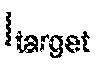 s provided as an input to multiplier 501. Multiplier 501 also receives as another input a phasor value ^33® from rotor position observer 208. Multiplier 501 multiplies its two inputs and provides a resulting output to adder 503 as an input. Adder 503 receives a P term feedback signal, such as from P term block 308, as another input. The P term feedback signal is provided from current observer 126 observing the current signals from motor 124 and current observer 126 providing the observed current signals to a Clarke converter 1 14. Clarke converter 114 performs Clarke transformations on the signals received from current observer 128. The Clarke transformed output from Clarke converter 1 14 is fed to adder 503. As the Clarke and inverse Ciarke transform are linear operations, the P term is not limited to calculation between the Clarke and inverse Clarke transforms but may be performed directly on the three signal motor signals. In this mode of implementation in which the calculations are performed directly, some further computational improvements may be possible.
[0031] Adder 503 adds the two inputs to provide as an output an error current ΙβΓΓ0Γ. Error current leETOr is fed into the I term block 306. I term block 306 also receives the phasor value e1^388 from rotor position observer 208. The error current !enw is also fed into adder 506 as an input, and adder 508 also receives the output of I term block 308 as another input. Adder 508 adds its two inputs and provides its output to inverse Clarke converter 1 10. Inverse Clarke converter 1 10 performs an inverse Clarke transformation on the output from adder 506 and provides the inverse Clarke transformed signals as an input to PWM block 112, PWM block 12 supplies its output signals to inverter 122 which is coupled to power supply 122 and motor 124.
[0032] Figure 5B shows an exemplary embodiment of a mathematical implementation and model 530 for the integral path term 308 shown in Figure 5A. Mathematical implementation and model 530 shows a multiplier 502 multiplying the error current lPjm with a phasor value eiphas<3. The resulting output of multiplier 502 is provided to adder 504. The output of adder 504 is then fed into delay (Z"1) block 508. The output of delay block 506 is fed to another multiplier 508 and also fed back as another input to adder 504. Another input to multiplier 508 is an inverse phasor value e"jphass. Multiplier 508 multiplies the output from the inverse delay block 506 with the inverse phasor value e'Jpi1i3se and provides a respective multiplication result. Mathematical implementation and model 530 shows all of its values and calculations as being complex.
[0033] Two multipliers 502 and 508 are shown in model 530 because they are reflective of the complex nature of the mathematical calculations for model 530. The mathematical calculations for model 530 are complex for at least the reason of the PI controller being inclusive of PI Q controller 104 and PI D controller 108. As indicated earlier, PI Q controller 104 provides the Q integral aspects of the PI controller while the PI D controller 108 provides the D integral aspects of the PI controller. Since two integral aspects need to be mathematically processed in model 530, two multipliers 502 and 508 are needed. State variables that are representative of the D and Q integral aspects of the integrator are defined and used for the calculations in model 530.
[0034] Figure 5C shows another exemplary embodiment of a mathematical implementation and model 550 for the integral path term 308 shown in Figure 5A. Mathematical implementation and model 550 shows an adder 504, a multiplier 502, and an delay (Z~1) biock 508 coupled together in series. Adder 504 adds the error current !efrorand the fed-back output signal of inverse delay (Z ) block 506. The resulting output of adder 504 is fed into multiplier 502. Multiplier 502 also receives as another input a frequency compensation factor e^. Complex multiplier 502 multiplies the resulting output from adder 504 and the frequency compensation factor e"Jfr¾q and provides the multiplied output to delay block 508. delay block 508 provides the resulting mathematical output,
[0035] Mathematical implementation and model 550 show a reduction in computation from mathematical implementation and model 530 because model 550 uses frequency rotation, in which the frequency is the derivative of the phase. Model 550 sti!S involves defining state variables that are representative of the D and Q integral aspects of the integrator. However, model 550 further involves combining the state variables into a single complex state variable that is maintained in the stator frame of reference, The single complex state variable is further multiplied by a complex rotator. The complex rotator is set in conformity with a frequency of the motor (e.g., motor 124). Thus, model 550 requires only one multiplier 502 performing only one complex multiplication operation because the state variables have been combined into a single complex state variable,
[0038] Figure 6 shows a timing diagram 600 of the error current !8rror being sampled and how the error current sampling relates to a pulse width modulation {PVVM} cycle. PWSvt waveform 602 shows the cycles within which the proportionate path calculations and the integral path calculations are performed. Timing diagram 600 shows that within one sampling cycle, proportionate path calculations are performed within time interval 604 while the integral path
caiculaiions are performed within the time interval 608. Timing diagram 800 further shows for a iater cycle (whether the later cycle is a next cycle or subsequent cycle), proportionate path calculations are performed within time interval 808 while the integral path calculations are performed within the time interval 610.
[0037] During a PWM update period, the proportionate path calculations are more quickly performed and allow the current error to be determined in a PWM trough (e.g., the time period that at least includes time intervals 606 and 808 as shown in Figure 8). At a Iater leading edge (that can be either a next leading edge or a subsequent leading edge) of the PWM waveform 802 (e.g., the leading edge that occurs between time interval 608 and time interval 610), the proportionate path calculations (and thus the error current for the Iater PWM cycle) are already determined and up to date before all computations (e.g., the integral path calculations) and other control functions are completed. In other words, the proportionate path calculations are already performed and up-to-date for the present PWM cycle while the integral path calculations are still being performed for a later PWM cycle (whether the Iater PWM cycle is a next PWM cycle or subsequent PWM cycle). Such a motor control system arrangement allows for faster feedback, provides for more loop bandwidth and phase margin for the closed loop system, provides higher signal fidelity, and faster response, as well as allows operation at higher motor speeds when compared with conventional motor control operations.
[0038] Although embodiments have been described in detail, it should be understood that various changes, substitutions, and alterations can be made hereto without departing from the spirit and scope of the invention as defined by the appended claims.
Claims
1. A method of controlling a motor, comprising: observing a motor current of the motor at a samp!ing rate; calculating, for a present cycle of the sampling rate, a proportionate path term for a proportionate-integrai control loop based on the motor current; outputting a respective motor output voltage to the motor in conformity with the proportionate path term calculated for the present cycle; and in conformity with the motor current, calculating an integral path term for another respective motor output voltage to be used in a later cycle of the sampling rate.
2. The method according to Claim 1 , further comprising: using an inverse Clarke converter to process the integral path term; and using a Clarke converter to provide the proportionate path term.
3. The method according to Claim 1 , wherein calculating an integral path term further comprises: calculating, by an Integra! path, the integral path term by performing at least a Park transformation, an integral operation, and an inverse Park transformation on the motor current fed back from the motor.
4. The method according to Claim 3, wherein calculating, for a present cycle of the sampling rate, a proportionate path term further comprises: calculating, by a proportionate path, the proportionate path term outside of the integral path.
5. The method according to Claim 1 , wherein calculating an integral path term further comprises: defining state variables that are representative of D and Q integral aspects of the proportionate-integral control ioop; combining the state variables Into a complex state variable; and
multiplying the complex state variable by a complex rotator that is set in conformity with a frequency of the motor,
6. The method according to Claim 1 , wherein the later cycle is a next cycle of the sampling rate.
7. A system for controlling a motor, comprising: a motor current control feedback loop that receives an error current as an input and provides a respective motor output voltage for driving the motor as an output wherein the motor current control feedback loop has a current control algorithm block, a current observer for observing a motor current at a sampling rate, and a proportionate-integral controller that provides a proportionate path and an integral path and at ieast forms part of a proportionate- integral control loop based on the motor current; and wherein, for a present cycle of the sampling rate, the proportionate path calculates a proportionate path term for the proportionate-integral control loop; wherein the respective motor output voltage to the motor is outputted in conformity with the proportionate path term calculated for the present cycle; and wherein, in conformity with the motor current, the integral path calculates an integral path term for another respective motor output voltage to be used in a later cycle of the sampling rate.
8. The system according to Claim 7, wherein the motor current control feedback loop further comprises: an inverse Clarke converter that is used for processing the integral path term; and a Clarke converter that is used for providing the proportionate path term.
9. The system according to Claim 7, wherein the integral path further comprises at Ieast: a Park converter for performing a Park transformation on the motor current fed back from the motor; an integrator block coupled to the Park converter wherein the integrator block performs integration on signals from the Park converter; and
an inverse Park converter coupled to the integrator block wherein the inverse Park converter performs an inverse Park transformation on integrated signals from the integrator block.
10. The system according to Claim 9, wherein the proportionate path calculates the proportionate path term outside of the integral path.
11. The system according to Claim 8, wherein the integral path caiculates the integral path term by defining state variables that are representative of D and Q integral aspects of the proportionate-integral control loop, combining the state variables into a complex state variable, and multiplying the complex state variable by a complex rotator that is set in conformity with a frequency of the motor.
12. The system according to Claim 7, wherein the later cycle is a next cycle of the sampling rate.
13. The system according to Claim 7, wherein the system is an integrated circuit.
14. A method for calculating an integral path term of an integral path for a proportionate- integral control loop for a motor controller controlling a motor current for a motor, comprising: defining state variables that are representative of D and Q integral aspects of the proportionate-integral control loop; combining the state variables into a complex state variable; and multiplying the complex state variable by a complex rotator that is set in conformity with a frequency of the motor.
15. The method according to Claim 14, further comprising: using an inverse Clarke converter for processing the integral path term.
16. The method according to Claim 14, wherein defining state variables, combining the state variables, and multiplying the complex state variable by a complex rotator further comprises; performing at least a Park transformation, an integral operation, and an inverse Park transformation on the motor current fed back from the motor.
17. A system for calculating an integral path term of an integral path for a proportionate- integral control loop for a motor controller controlling a motor current for a motor, comprising: a proportionate-integral control loop having state variabies defined that are representative of D and Q integral aspects of the proportionate-integral controi loop, wherein the state variabies are combined into a complex state variable and the complex state variable is multiplied by a complex rotator that is set in conformity with a frequency of the motor,
18. The system according to Claim 17 further comprising: an inverse Clarke converter that is used for processing the Integral path term.
19. The system according to Claim 17, wherein the integral path further comprises: a Park converter for performing a Park transformation on the motor current fed back from the motor; an integrator block coupled to the Park converter wherein the integrator block performs integration on signals from the Park converter; and an inverse Park converter coupled to the integrator block wherein the inverse Park converter performs an inverse Park transformation on integrated signals from the integrator block.
20. The system according to Claim 17, wherein the system is an Integrated circuit.
Applications Claiming Priority (2)
| Application Number | Priority Date | Filing Date | Title |
|---|---|---|---|
| US13/827,031 | 2013-03-14 | ||
| US13/827,031 US9035587B2 (en) | 2013-03-14 | 2013-03-14 | Motor control loop with fast response |
Publications (2)
| Publication Number | Publication Date |
|---|---|
| WO2014158976A2 true WO2014158976A2 (en) | 2014-10-02 |
| WO2014158976A3 WO2014158976A3 (en) | 2015-10-01 |
Family
ID=50349949
Family Applications (1)
| Application Number | Title | Priority Date | Filing Date |
|---|---|---|---|
| PCT/US2014/021217 Ceased WO2014158976A2 (en) | 2013-03-14 | 2014-03-06 | Motor control loop with fast response |
Country Status (2)
| Country | Link |
|---|---|
| US (1) | US9035587B2 (en) |
| WO (1) | WO2014158976A2 (en) |
Families Citing this family (4)
| Publication number | Priority date | Publication date | Assignee | Title |
|---|---|---|---|---|
| CN108347207B (en) * | 2018-03-14 | 2021-01-15 | 包头长安永磁电机有限公司 | Position and speed estimation method of permanent magnet synchronous motor based on complex PI controller |
| CN110768590B (en) * | 2018-07-25 | 2021-06-15 | 哈尔滨工业大学 | A system and method for estimating rotor position and speed of permanent magnet synchronous motor |
| CN111211720B (en) * | 2019-12-30 | 2021-11-12 | 东风航盛(武汉)汽车控制系统有限公司 | Method for setting PI (proportional integral) parameter of current loop of permanent magnet synchronous motor controller |
| JP7770545B2 (en) * | 2023-09-25 | 2025-11-14 | 上海利▲ク▼科技有限公司 | Motor rotation control method and device |
Citations (1)
| Publication number | Priority date | Publication date | Assignee | Title |
|---|---|---|---|---|
| US20120249033A1 (en) | 2011-04-01 | 2012-10-04 | Texas Instruments Incorporated | Sensorless motor control |
Family Cites Families (7)
| Publication number | Priority date | Publication date | Assignee | Title |
|---|---|---|---|---|
| JP3336870B2 (en) * | 1996-09-04 | 2002-10-21 | 三菱電機株式会社 | Method and apparatus for controlling rotating magnet type polyphase synchronous motor |
| JP3421277B2 (en) * | 1998-08-26 | 2003-06-30 | 三菱電機株式会社 | Motor drive control device and motor drive control method |
| JP3527207B2 (en) * | 2001-02-16 | 2004-05-17 | 本田技研工業株式会社 | Motor control device |
| US7075264B2 (en) * | 2004-03-31 | 2006-07-11 | Honeywell International Inc. | Instantaneous power floating frame controller |
| US20060043923A1 (en) * | 2004-08-31 | 2006-03-02 | Baker Donal E | Performance enhancement for motor field oriented control system |
| US7339344B2 (en) * | 2005-08-25 | 2008-03-04 | International Rectifier Corporation | Self tuning method and apparatus for permanent magnet sensorless control |
| US7348758B2 (en) * | 2005-10-26 | 2008-03-25 | International Rectifier Corporation | Audible noise reduction for single current shunt platform |
-
2013
- 2013-03-14 US US13/827,031 patent/US9035587B2/en not_active Expired - Fee Related
-
2014
- 2014-03-06 WO PCT/US2014/021217 patent/WO2014158976A2/en not_active Ceased
Patent Citations (1)
| Publication number | Priority date | Publication date | Assignee | Title |
|---|---|---|---|---|
| US20120249033A1 (en) | 2011-04-01 | 2012-10-04 | Texas Instruments Incorporated | Sensorless motor control |
Non-Patent Citations (1)
| Title |
|---|
| RETT NOVAK; BILAL AKIN, DESIGNING HIGH-PERFORMANCE AND POWER-EFFICIENT MOTOR CONTROL SYSTEMS, June 2009 (2009-06-01) |
Also Published As
| Publication number | Publication date |
|---|---|
| US20140265968A1 (en) | 2014-09-18 |
| WO2014158976A3 (en) | 2015-10-01 |
| US9035587B2 (en) | 2015-05-19 |
Similar Documents
| Publication | Publication Date | Title |
|---|---|---|
| Khlaief et al. | A MRAS-based stator resistance and speed estimation for sensorless vector controlled IPMSM drive | |
| JP5982901B2 (en) | Electric motor control device and electric motor control method | |
| JP5396876B2 (en) | AC motor control device | |
| EP2020743B1 (en) | Sensorless controlling apparatus for controlling a brushless motor | |
| US8294395B2 (en) | Controller for AC rotary machine and controller for electric power steering | |
| US20030052641A1 (en) | Motor control apparatus and motor control method | |
| WO2011105355A1 (en) | Torque ripple suppression control apparatus and torque ripple suppression control method for rotating electrical machine | |
| KR101840509B1 (en) | Rotation angle estimation module for sensorless vector control of PMSM | |
| KR101353583B1 (en) | Speed controller using parameter estimation of interior permanent magnet synchronous motor and its method | |
| US6954050B2 (en) | Control method and control device of permanent-magnet type synchronous motor | |
| CN103733504B (en) | The position-sensorless control device of PM motor | |
| EP2808998B1 (en) | Control device for alternating current rotary machine | |
| KR20190064832A (en) | Parameter estimation method and apparatus of Surface Mounted Permanent Magnet Synchronous Motor | |
| JP2011176951A (en) | Torque controller for motor | |
| CN111656676A (en) | Control device for power conversion device and motor drive system | |
| JP2013106514A (en) | Method and system for controlling motor | |
| WO2014158976A2 (en) | Motor control loop with fast response | |
| EP2290806B1 (en) | Control apparatus for synchronous motor | |
| JP5230682B2 (en) | Control device for synchronous motor | |
| JP2011217505A (en) | Controller of synchronous motor and control method of synchronous motor | |
| CN106487305A (en) | For the method for carrying out field orientation regulation to the frequency converter for three-phase alternating-current motor | |
| RU99911U1 (en) | MULTI-PHASE MOTOR MOTOR VECTOR SENSOR-FREE CONTROL SYSTEM | |
| US20060049796A1 (en) | Control device for alternating-current motor | |
| JP6417881B2 (en) | Induction motor controller | |
| EP4454119B1 (en) | Method and system for controlling an electric machine driven by an inverter provided with a plurality of switching arms |
Legal Events
| Date | Code | Title | Description |
|---|---|---|---|
| 121 | Ep: the epo has been informed by wipo that ep was designated in this application |
Ref document number: 14712503 Country of ref document: EP Kind code of ref document: A2 |
|
| 122 | Ep: pct application non-entry in european phase |
Ref document number: 14712503 Country of ref document: EP Kind code of ref document: A2 |