WO2014156913A1 - 光音響計測装置 - Google Patents
光音響計測装置 Download PDFInfo
- Publication number
- WO2014156913A1 WO2014156913A1 PCT/JP2014/057648 JP2014057648W WO2014156913A1 WO 2014156913 A1 WO2014156913 A1 WO 2014156913A1 JP 2014057648 W JP2014057648 W JP 2014057648W WO 2014156913 A1 WO2014156913 A1 WO 2014156913A1
- Authority
- WO
- WIPO (PCT)
- Prior art keywords
- signal
- detector element
- acoustic wave
- circuit
- contact
- Prior art date
- Legal status (The legal status is an assumption and is not a legal conclusion. Google has not performed a legal analysis and makes no representation as to the accuracy of the status listed.)
- Ceased
Links
Images



Classifications
-
- A—HUMAN NECESSITIES
- A61—MEDICAL OR VETERINARY SCIENCE; HYGIENE
- A61B—DIAGNOSIS; SURGERY; IDENTIFICATION
- A61B8/00—Diagnosis using ultrasonic, sonic or infrasonic waves
- A61B8/44—Constructional features of the ultrasonic, sonic or infrasonic diagnostic device
- A61B8/4477—Constructional features of the ultrasonic, sonic or infrasonic diagnostic device using several separate ultrasound transducers or probes
-
- A—HUMAN NECESSITIES
- A61—MEDICAL OR VETERINARY SCIENCE; HYGIENE
- A61B—DIAGNOSIS; SURGERY; IDENTIFICATION
- A61B5/00—Measuring for diagnostic purposes; Identification of persons
- A61B5/0093—Detecting, measuring or recording by applying one single type of energy and measuring its conversion into another type of energy
- A61B5/0095—Detecting, measuring or recording by applying one single type of energy and measuring its conversion into another type of energy by applying light and detecting acoustic waves, i.e. photoacoustic measurements
-
- A—HUMAN NECESSITIES
- A61—MEDICAL OR VETERINARY SCIENCE; HYGIENE
- A61B—DIAGNOSIS; SURGERY; IDENTIFICATION
- A61B8/00—Diagnosis using ultrasonic, sonic or infrasonic waves
- A61B8/42—Details of probe positioning or probe attachment to the patient
- A61B8/4272—Details of probe positioning or probe attachment to the patient involving the acoustic interface between the transducer and the tissue
- A61B8/429—Details of probe positioning or probe attachment to the patient involving the acoustic interface between the transducer and the tissue characterised by determining or monitoring the contact between the transducer and the tissue
-
- A—HUMAN NECESSITIES
- A61—MEDICAL OR VETERINARY SCIENCE; HYGIENE
- A61B—DIAGNOSIS; SURGERY; IDENTIFICATION
- A61B8/00—Diagnosis using ultrasonic, sonic or infrasonic waves
- A61B8/44—Constructional features of the ultrasonic, sonic or infrasonic diagnostic device
- A61B8/4483—Constructional features of the ultrasonic, sonic or infrasonic diagnostic device characterised by features of the ultrasound transducer
- A61B8/4488—Constructional features of the ultrasonic, sonic or infrasonic diagnostic device characterised by features of the ultrasound transducer the transducer being a phased array
Definitions
- the present invention relates to a photoacoustic measurement apparatus, and more particularly to a photoacoustic measurement apparatus that emits light to a subject and detects a photoacoustic wave generated in the subject by the light emission.
- An ultrasonic inspection method is known as a kind of image inspection method capable of non-invasively examining the state inside a living body.
- an ultrasonic probe capable of transmitting and receiving ultrasonic waves is used.
- the ultrasonic waves travel inside the living body and are reflected at the tissue interface.
- the reflected ultrasound is received by the ultrasound probe, and the internal state can be imaged by calculating the distance based on the time until the reflected ultrasound returns to the ultrasound probe. .
- photoacoustic imaging in which the inside of a living body is imaged using the photoacoustic effect.
- a living body is irradiated with pulsed laser light. Inside the living body, the living tissue absorbs the energy of the pulsed laser light, and ultrasonic waves (photoacoustic waves) are generated by adiabatic expansion due to the energy.
- ultrasonic waves photoacoustic waves
- Patent Document 1 describes that ultrasonic waves are transmitted from a probe, whether or not contact is sufficient based on an ultrasonic reception signal, and light irradiation is performed when the contact is sufficient. Has been.
- reflected ultrasonic waves reflected in a subject are received by a processing device that generates an ultrasonic image.
- the processing device generates an ultrasonic image while sending an ultrasonic reception signal to the control device of the light source.
- the control device determines the contact state based on the ultrasonic wave reception signal received from the processing device. For this reason, ultrasonic image generation and contact state determination cannot be performed separately. For example, when a processing device that generates an ultrasonic image goes down, an ultrasonic reception signal can be received from the processing device. Therefore, the contact state cannot be determined.
- an object of the present invention is to provide a photoacoustic measurement apparatus capable of performing contact determination processing separately from signal processing such as image generation.
- the present invention provides a light source unit including a light source and a plurality of detector elements capable of detecting acoustic waves and transmitting acoustic waves, the first detector element and the second detector element.
- An acoustic wave detecting means having a plurality of detector elements including a detector element, a probe including a light emitting portion that emits light emitted from the light source in the direction of the subject, and a plurality of detector elements of the acoustic wave detecting means
- the first detector element is connected to the first detector element, and after the light emitted from the light source is emitted to the subject, the light is emitted in the subject and detected by the first detector element.
- a signal processing unit including a receiving circuit for receiving the detected signal of the photoacoustic wave, a signal processing means for signal-processing the detected signal of the photoacoustic wave received by the receiving circuit, and a plurality of detector elements of the acoustic wave detecting means Connected to a second detector element of After the acoustic wave is transmitted from at least a part of the number of detector elements, an acoustic wave detection signal detected by the second detector element is received, and a probe is received based on the received acoustic wave detection signal
- a contact determining means for determining whether or not the probe is in contact with the subject, and a light emission control means for emitting light from the light emitting portion when it is determined that the probe is in contact with the subject.
- a characteristic photoacoustic measuring device is provided.
- the contact determination means and the light emission control means are preferably arranged in the light source unit.
- a plurality of second detector elements and a plurality of contact determination means are provided, and the light emission control means has a light emitting portion when at least one of the plurality of contact determination means determines that the probe is in contact with the subject. It is also preferable to emit light from
- the contact determination means generates a detection signal from the transmission of the acoustic wave until the time corresponding to the distance between the acoustic wave detection surface of the second detector element and the surface of the probe contacting the subject passes. Based on this, it may be determined whether the probe is in contact with the subject.
- the signal processing unit may further include a transmission circuit that transmits an acoustic wave from the first detector element.
- the receiving circuit may further receive a detection signal of the reflected acoustic wave with respect to the acoustic wave transmitted from the first detector element, and the signal processing unit may further process the detection signal of the reflected acoustic wave.
- the contact determination means can employ a configuration in which a detection signal of the acoustic wave detected by the second detector element is received after the transmission circuit transmits the acoustic wave.
- the contact determination means transmits an acoustic wave from the second detector element, and receives the acoustic wave detection signal detected by the second detector element after transmitting the acoustic wave. It can also be adopted.
- a plurality of detector elements including the first detector element and the second detector element may be arranged at least one-dimensionally.
- the second detector element may be arranged at at least one end in the arrangement direction.
- positioned between the two 1st detector elements adjacent along the sequence direction may be sufficient.
- one contact judgment means receiving the sum of the detection signal of the acoustic wave detected by a plurality of 2nd detector elements.
- the contact determination means may determine that contact is made when the maximum value of the received acoustic wave detection signal is equal to or less than a threshold value.
- the contact determination means includes a folding circuit that folds a negative signal of the acoustic wave detection signal detected by the second detector element into a positive signal, a low-pass filter circuit that performs low-pass filtering on the output signal of the folding circuit, A comparison circuit that compares the output signal level of the filter circuit and a voltage corresponding to the threshold value can be used.
- the contact determination means may integrate the received acoustic wave detection signal and determine that the contact is made when the integrated value is equal to or less than a threshold value.
- the contact determination means includes a folding circuit that folds a negative signal of the acoustic wave detection signal detected by the second detector element into a positive signal, a low-pass filter circuit that performs low-pass filtering on the output signal of the folding circuit, An integration circuit that integrates the output signal of the filter circuit and a comparison circuit that compares the output signal level of the integration circuit with a voltage corresponding to the threshold value can be used.
- the present invention also includes a light source unit including a light source, a plurality of detector elements capable of detecting an acoustic wave and transmitting an acoustic wave, an acoustic wave detecting unit having the detector element, and the light source
- a probe including a light emitting unit that emits light toward the subject, a preamplifier that amplifies the detection signal of the detector element, and the detector element and the preamplifier connected to each other, and the light emitted from the light source is applied to the subject
- a reception circuit that receives a detection signal of a photoacoustic wave generated in the subject due to light emission and detected by the detector element after being emitted, and a detection signal of the photoacoustic wave received by the reception circuit
- the detection signal of the detector element is input via the signal processing unit including the signal processing means for signal processing, and the wiring branched from the wiring connecting the preamplifier and the receiving circuit, and the detection signal of the detector element is output.
- the detector is connected to the width detector, the detector element and the buffer amplifier, and after the acoustic wave is transmitted from the detector element, the detection signal of the acoustic wave detected by the detector element is received, and the received acoustic wave is detected.
- Contact determining means for determining whether or not the probe is in contact with the subject based on the signal, and light emission control means for emitting light from the light emitting section when it is determined that the probe is in contact with the subject.
- the photoacoustic measuring device provided with this is provided.
- the output impedance of the preamplifier is preferably lower than the input impedance of the buffer amplifier.
- the probe has a plurality of detector elements, the preamplifier is arranged corresponding to each of the plurality of detector elements, and the buffer amplifier connects the preamplifier and the receiving circuit.
- the detection signal of the detector element may be input via a wiring branched from at least a part of the plurality of wirings.
- the photoacoustic measuring device of the present invention further includes a protective switch on the input side of the buffer amplifier that cuts off the signal when a signal equal to or higher than the threshold voltage is applied.
- the photoacoustic measuring apparatus of the present invention further preferably has a protection circuit for limiting the input signal voltage to the buffer amplifier on the input side of the buffer amplifier.
- the number of buffer amplifiers is smaller than the number of branched lines, and a switch for selecting a line connected to the buffer amplifier among the branched lines is further provided between the branched line and the buffer amplifier. It may be a configuration.
- the signal path of the signal detected by the detector element can be separated, and the signal processing such as image generation and the contact determination processing can be performed separately without being linked.
- the block diagram which shows the acoustic wave detection means which has four 2nd detector elements for contact judgment.
- the figure which shows the connection of the acoustic wave detection means which has several detector elements, a preamplifier, and a buffer.
- FIG. 1 shows a photoacoustic measurement apparatus according to an embodiment of the present invention.
- the photoacoustic measurement device 10 includes a probe 11, a signal processing unit 12, and a light source unit 13.
- the photoacoustic measuring device 10 can generate both an ultrasonic image and a photoacoustic image.
- an ultrasonic wave is used as an acoustic wave.
- the ultrasonic wave is not limited to an ultrasonic wave, and is audible as long as an appropriate frequency is selected in accordance with an object to be examined and measurement conditions.
- An acoustic wave having a frequency may be used.
- the light source unit 13 generates light (laser light) emitted toward the subject.
- the probe 11 detects photoacoustic waves generated in the subject due to the light emission after the light is emitted to the subject.
- transmission of acoustic waves (ultrasound) to the subject and reception of reflected acoustic waves (reflected ultrasound) for the transmitted acoustic waves are performed.
- the signal processing unit 12 generates a photoacoustic image based on a photoacoustic wave detection signal (photoacoustic signal) detected by the probe 11. Further, an ultrasonic image (reflected acoustic wave image) is generated based on a detection signal (reflected ultrasonic signal) of the reflected ultrasonic wave detected by the probe 11.
- the probe 11 has an acoustic wave detection means 16 and a light emitting part 17.
- the acoustic wave detection means 16 has a plurality of detector elements that can detect acoustic waves and transmit acoustic waves.
- the plurality of detector elements include one or more first detector elements and one or more second detector elements.
- the first detector element is a detector element for image acquisition, and the second detector element is a detector element for contact determination.
- the light emitting unit 17 emits light from the light source unit 13 toward the subject.
- the signal processing unit 12 includes a transmission / reception switching circuit 21, a reception circuit 22, a transmission circuit 23, an image generation means 24, and a transmission / reception control circuit 25.
- the transmission / reception switching circuit 21 switches between transmission and reception of ultrasonic waves.
- the transmission / reception switching circuit 21 is connected to a first detector element among the plurality of detector elements of the acoustic wave detection means 16.
- the transmission / reception switching circuit 21 connects the first detector element and the receiving circuit 22 when receiving ultrasonic waves, and connects the transmitting circuit 23 and the first detector element when transmitting acoustic waves.
- the transmission / reception control circuit 25 controls transmission and reception of acoustic waves.
- the transmission circuit 23 generates a transmission signal.
- the transmission circuit 23 sends a transmission signal to the first detector element of the acoustic wave detection means 16 via the transmission / reception switching circuit 21.
- the first detector element of the acoustic wave detecting means 16 is driven according to the transmission signal, and ultrasonic waves are transmitted from the first detector element.
- the reception circuit 22 receives an ultrasonic signal output from the first detector element of the acoustic wave detection means 16 via the transmission / reception switching circuit 21.
- the ultrasonic signal received by the receiving circuit 22 includes a photoacoustic signal and a reflected ultrasonic signal.
- the image generation unit 24 is a signal processing unit, and generates an image based on the ultrasonic signal received by the reception circuit 22. More specifically, the image generation unit 24 generates a photoacoustic image based on the photoacoustic signal, and generates an ultrasonic image based on the reflected ultrasonic signal. Note that image generation is not essential, and the image generation unit 24 may simply perform some signal processing on the ultrasonic signal. Further, signal processing (image generation) with respect to reflected ultrasound may be omitted.
- the light source unit 13 includes a contact determination unit 31, a light emission control unit 32, and a light source (light emitting unit) 33.
- the contact determination unit 31 is connected to a second detector element among the plurality of detector elements of the acoustic wave detection unit 16.
- the contact determination unit 31 detects a reflected ultrasonic wave detection signal (reflected) detected by the second detector element after ultrasonic waves are transmitted from at least some of the plurality of detector elements of the acoustic wave detection unit 16. (Ultrasonic signal) is received.
- the contact determination unit 31 determines whether or not the probe 11 is in contact with the subject based on the reflected ultrasonic signal output from the second detector element.
- the contact determination means 31 determines that the probe 11 is in contact with the subject when the maximum value of the reflected ultrasonic signal received from the second detector element is smaller than the threshold value, for example.
- the reflected ultrasonic signal detected by the second detector element is received at a distance between the ultrasonic detection surface of the probe 11 and the surface of the probe tip that contacts the subject from the transmission timing of the ultrasonic wave. It only needs to be done until the corresponding time has elapsed. That is, the contact determination unit 31 is from the transmission of the ultrasonic wave until the time corresponding to the distance between the ultrasonic detection surface of the second detector element and the surface of the probe 11 that contacts the subject elapses. Whether or not the probe is in contact with the subject may be determined based on the detection signal.
- the contact determination unit 31 monitors the reflected ultrasonic signal output from the second detector element for a certain period, and reflects the reflected ultrasonic signal in that period. Threshold processing is performed on the maximum value of the sound wave signal. When the maximum value of the reflected ultrasonic signal is smaller than the threshold value, it is determined that the probe 11 is in contact with the subject.
- the distance between the ultrasonic detection surface and the surface of the probe tip that contacts the subject is increased by the thickness of the attachment.
- the magnitude of reflected ultrasonic waves generated at the interface between the tip of the probe 11 (attachment tip) and air varies depending on the attachment to be used.
- the threshold value of the reflected ultrasonic signal which is a reference for contact determination, may be appropriately changed according to the attachment to be used.
- the period for monitoring the reflected ultrasound signal may be adjusted according to the thickness of the attachment to be used (distance between the surface on the ultrasonic detection surface side and the surface on the subject side).
- the light source 33 emits light (laser light) emitted toward the subject. What is necessary is just to set the wavelength of a laser beam suitably according to an observation target object.
- the light emission control means 32 controls the light emission of the light source 33.
- the light emission control unit 32 causes the light source 33 to emit light when the contact determination unit 31 determines that the probe is in contact with the subject.
- the light emitted from the light source 33 is guided to the probe 11 using a light guide means such as an optical fiber, and is emitted from the light emitting portion 17 of the probe 11.
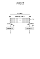
- FIG. 2 shows the acoustic wave detection means 16.
- the acoustic wave detection means 16 includes, for example, a plurality of detector elements arranged one-dimensionally. Of the plurality of arranged detector elements, detector elements at both ends in the arrangement direction are set as second detector elements 162, and the remaining detector elements are set as first detector elements 161. For example, when a total of 130 detector elements are arranged one-dimensionally, the two detector elements 1ch and 130ch at both ends are used as the second detector elements 162 for contact determination, and 2ch to The 128 detector elements of 129ch are defined as first detector elements 161 for image acquisition. Note that the second detector elements 162 are not necessarily provided at both ends in the arrangement direction of the detector elements, and either one of them may be provided. Further, the arrangement of the detector elements is not limited to a one-dimensional arrangement. A plurality of detector elements may be arranged two-dimensionally.
- the first detector element 161 for image acquisition is connected to the reception circuit 22 or the transmission circuit 23 via the transmission / reception switching circuit 21.
- a multiplexer is provided between the transmission / reception switching circuit 21 and the first detector element 161, and some of the 128 first detector elements 161 are selectively connected to the reception circuit 22 or the transmission circuit 23. You may make it do.
- the multiplexer can be used for, for example, ultrasonic line-by-line scanning and region selection when acquiring a photoacoustic image. When transmitting ultrasonic waves for contact determination, it is not necessary to transmit ultrasonic waves from all of the first detector elements 161 provided in the acoustic wave detection means 16, but to transmit from a part thereof. Also good.
- the two second detector elements 162 for contact determination are connected to the corresponding contact determination means 31, respectively.
- Each contact determination means 31 determines whether or not the reflected ultrasonic signal output from the connected second detector element 162 is smaller than a threshold value.
- the light emission control unit 32 (see FIG. 1) controls the light source 33 based on the determination results in the two contact determination units 31.
- the light emission control means 32 is at least one of the plurality of contact determination means 31 and the probe 11 is the subject.
- the light emission control unit 32 may cause the light source 33 to emit light only when both the two contact determination units 31 determine that the probe 11 is in contact with the subject.
- the receiving circuit 22 is connected to only the first detector element 161 among the first detector element and the second detector element provided in the acoustic wave detecting means 16 via the transmission / reception switching circuit 21. Connected and not connected to the second detector element 162. Therefore, the signal detected by the second detector element 162 is not used for generating a photoacoustic image.
- the contact determination means 31 is connected only to the second detector element 162 out of the first detector element and the second detector element provided in the acoustic wave detection means 16, and the first detector It is not connected to the element 161. Therefore, the signal detected by the first detector element 162 is not used for contact determination.
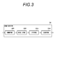
- FIG. 3 shows the configuration of the contact determination means 31.
- the contact determination unit 31 includes, for example, an amplifier circuit 311, a folding circuit 312, an LPF (Low Pass Filter) circuit 313, and a comparison circuit 314.
- the amplifier circuit 311 amplifies the reflected ultrasound signal output from the second detector element 162 (see FIG. 2). If the reflected ultrasonic signal output from the second detector element 162 is sufficiently large, the amplifier circuit 311 may be omitted.
- the folding circuit 312 includes, for example, a diode bridge circuit, converts the negative signal of the reflected ultrasonic wave amplified by the amplifier circuit 311 into a positive signal, and outputs the positive signal to the LPF 313.
- the LPF circuit 313 performs low-pass filter processing on the output signal of the folding circuit 312 and cuts the high-frequency component of the signal.
- the comparison circuit 314 compares the output signal level of the LPF circuit 313 with the voltage corresponding to the threshold value for contact determination.
- the comparison circuit 314 outputs a signal indicating that the probe 11 is in contact with the subject when the output signal level of the LPF circuit 313 is equal to or lower than the voltage corresponding to the threshold value.
- a signal indicating that the probe 11 is not in contact with the subject may be output.
- FIG. 4 shows an operation procedure.
- the transmission / reception control circuit 25 transmits / receives a transmission / reception switching circuit 2 for ultrasonic transmission. 1 is connected to the transmission circuit 23.
- the transmission circuit 23 sends a transmission signal to the first detector element 161 (see FIG. 2) of the acoustic wave detection means 16 via the transmission / reception switching circuit 21, and causes the first detector element 161 to transmit ultrasonic waves. (Step S1).
- the transmission / reception control circuit 25 connects the transmission / reception switching circuit 21 to the reception circuit 22 after ultrasonic transmission.
- the receiving circuit 22 receives the reflected ultrasonic signal output from the first detector element 161 via the transmission / reception switching circuit 21 (step S2).
- the image generation unit 24 generates an ultrasonic image based on the received reflected ultrasonic signal (step S3).
- the photoacoustic measurement apparatus 10 transmits and receives ultrasonic waves on a line by line, and generates an ultrasonic image.
- the photoacoustic measuring device 10 transmits ultrasonic waves for contact determination prior to acquisition of the photoacoustic image after acquisition of the ultrasonic image.
- the transmission / reception control circuit 25 connects the transmission / reception switching circuit 21 to the transmission circuit 23 for ultrasonic transmission.
- the transmission circuit 23 sends a transmission signal to the first detector element 161 via the transmission / reception switching circuit 21 to transmit an ultrasonic wave from the first detector element 161 (step S4). It is not necessary to transmit ultrasonic waves from all the first detector elements 161 provided in the acoustic wave detection means 16, for example, some first detector elements in the vicinity of the second detector element 162. 161 may be performed.
- the second detector element 162 detects the reflected ultrasonic wave with respect to the ultrasonic wave transmitted in step S4 (step S5).
- the contact determination means 31 receives the reflected ultrasonic signal output from the second detector element 162, and determines whether or not a strong reflected ultrasonic wave is detected by the second detector element 162 (step S6).
- each of the plurality of contact determination units 31 determines whether or not a strong reflected ultrasonic wave is detected by the second detector element 162. For example, when the signal level of the reflected ultrasonic signal output from the second detector element 162 is equal to or lower than the threshold value, the contact determination unit 31 receives the probe 11 from the comparison circuit 314 (see FIG. 3). An H level signal indicating contact (hereinafter referred to as contact) is output.
- the light emission control means 32 determines that the probe 11 is in contact with the subject when it is determined in step S6 that a strong reflected ultrasonic wave is not detected by the second detector element 162, and the light source 33 Allow to emit light.
- the light source 33 receives, for example, a trigger signal from the light emission control unit 32, performs laser oscillation, and emits laser light (step S7). If it is determined in step S6 that a strong reflected ultrasonic wave has been detected by the second detector element 162, the process ends. Or you may return to step S4 and may repeatedly perform step S4 to step S6 until a strong reflected ultrasonic wave is no longer detected.
- the light source 33 informs the signal processing unit 12 of the emission timing of the laser beam when emitting the laser beam in step S7.
- the transmission / reception control circuit 25 connects the transmission / reception switching circuit 21 to the reception circuit 22 in preparation for reception of photoacoustic waves.
- the connection destination of the transmission / reception switching circuit 21 may be switched at an arbitrary timing after the ultrasonic transmission in step S4 until the light source unit 13 emits light.
- the first detector element 161 detects the photoacoustic signal (step S8).
- the reception circuit 22 starts receiving the photoacoustic signal output from the first detector element 161 in accordance with the light emission timing of the light source 33.
- the image generation unit 24 generates a photoacoustic image based on the received photoacoustic signal (step S9).
- the ultrasonic image generated in step S3 and the photoacoustic image generated in step S9 are displayed on image display means such as a display (not shown).
- image display means such as a display (not shown).
- the ultrasonic image and the photoacoustic image are displayed in a superimposed manner after being aligned.
- the ultrasonic image and the photoacoustic image may be displayed side by side, or both may be switched and displayed.
- the acoustic wave detection means 16 includes a first detector element 161 and a second detector element 162.
- the detection signal detected by the first detector element 161 is sent to the signal processing unit 12 where signal processing such as image generation is performed.
- the detection signal detected by the second detector element 162 is sent to the contact determination means 31, and the contact determination means 31 performs a contact determination process.
- the first detector element 161 and the second detector element 162 have different signal output destinations and are divided in signal paths.
- the processing in the contact determination unit 31 is not affected by the signal processing in the signal processing unit 12, and the processing for contact determination can be performed separately without being linked with the processing for image generation. For this reason, for example, even when the signal processing unit 12 is down, the contact determination process is possible.
- the detector elements at both ends of the one-dimensionally arranged plurality of detector elements are the second detector elements 162 for contact determination.
- a detector element 162 may be inserted between the first detector elements 161 for image acquisition.
- the second detector element 162 may be disposed between two first detector elements 161 adjacent in the arrangement direction.
- the number of the second detector elements 162 is not limited to two as long as it is at least one.
- the acoustic wave detection means 16 may include three or more second detector elements 162.
- FIG. 5 shows acoustic wave detection means 16 having four second detector elements 162 for contact determination.
- the acoustic wave detection means 16 has a total of 132 detector elements, for example. Among them, a total of four detector elements 1ch, 49ch, 84ch, and 132ch are the second detector elements 162 for contact determination, and the remaining 128 detector elements are the first detector elements 161 for image acquisition. is there.
- four contact determination means 31 are also provided so as to correspond to the second detector elements 162 on a one-to-one basis.
- each contact determination unit 31 determines that there is contact (when the signal level of the reflected ultrasonic signal is equal to or lower than the threshold value (V th )), the contact determination unit 31 outputs an H level signal. When it is determined that there is no contact (the signal level of the reflected ultrasonic signal is higher than the threshold value (V th )), an L level signal is output.
- the second detector elements 162 are arranged at the two ends and the center of the acoustic wave detecting means 16, at least one of the ends is in contact with the subject and the center 2 Light emission may be performed when at least one of the locations is in contact with the subject.
- the output of the contact determination unit 31 corresponding to the second detector element 162 of 1ch and the output of the contact determination unit 31 corresponding to the second detector element 162 of 132ch are input to the input terminal of the OR circuit 35. Connecting. When it is determined that at least one of the two contact determination means 31 corresponding to both ends is in contact, the output of the OR circuit 35 is at the H level.
- the output of the contact determination means 31 corresponding to the 49ch second detector element 162 and the output of the contact determination means 31 corresponding to the 84ch second detector element 162 are connected to the input of the OR circuit 36. To do. When it is determined that at least one of the contact determination means 31 corresponding to the two second detector elements 162 in the center is in contact, the output of the OR circuit 36 is at the H level. The output of the OR circuit 35 and the output of the OR circuit 36 are connected to the input of the AND circuit 37. The output of the AND circuit 37 becomes H level when both the output of the OR circuit 35 and the output of the OR circuit 36 are at H level.
- the light emission control means 32 may emit light from the light source 33 when the output of the AND circuit 37 is at the H level. In this case, light can be emitted even when the entire ultrasonic detection surface of the probe 11 is not in contact with the subject.
- FIG. 6 shows a modification of the connection between the second detector element 162 and the contact determination means 31.
- the second detector elements 162 and the contact determination means 31 do not have to correspond one-to-one, and a plurality of second detector elements 162 and one contact determination means 31 may correspond to each other.
- the single contact determination unit 31 may receive the sum of the reflected ultrasonic signals detected by the plurality of second detector elements 162.
- the outputs of the second detector elements 162 at both ends of the acoustic wave detection means 16 are combined into one and connected to one contact determination means 31. Further, the outputs of the two second detector elements 162 at the center are combined into one and connected to one contact determination means 31.
- the contact determination means 31 corresponding to both ends determines whether or not the signal level of the sum of the reflected ultrasonic signals of the second detector elements 162 at both ends is equal to or lower than the voltage level corresponding to the threshold value.
- the threshold value at this time is set to twice (2 ⁇ V th ) the threshold value (V th ) in the contact determination means 31 in the case of FIG.
- the sum of the reflected ultrasound signals of the two second detector elements 162 is lower than 2 ⁇ Vth. .
- the contact determination unit 31 determines that there is a contact and outputs an H level signal if at least one of the second detector elements 162 at both ends is in contact. .
- the contact determining means 31 corresponding to the two second detector elements 162 in the center.
- the two second detector elements 162 may be the same value (V th ) as the threshold value in the case of FIG. In this case, when any one of the two second detector elements 162 is away from the subject, the sum of the reflected ultrasonic signals is larger than the threshold value Vth .
- the contact determination means 31 determines that there is a contact and outputs an H level signal when both of the two second detector elements 162 are in contact with the subject and only a weak reflected ultrasonic signal is detected. .
- the outputs of the two contact determination means 31 are connected to the input of the AND circuit 37.
- the output of the AND circuit 37 becomes H level when both contact determination means 31 output an H level signal indicating that there is contact. Similar to the case of FIG. 5, the light emission control means 32 only has to emit light from the light source 33 when the output of the AND circuit 37 is at the H level.
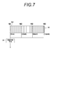
- FIG. 7 shows a further modification of the connection between the second detector element 162 and the contact determination means 31.
- one contact determination means 31 is provided for four second detector elements 162.
- the contact determination means 31 receives the sum of the reflected ultrasonic signals of the four second detector elements 162, and whether or not the signal level of the sum of the reflected ultrasonic signals is equal to or lower than the voltage level corresponding to the threshold value. Determine whether.
- the threshold value is three times the threshold value in the case of FIG. 5 (3 ⁇ V th )
- the contact determination means 31 has any one of the four second detector elements 162 as the subject. When it is in contact, it is determined that there is contact, and an H level signal is output.
- the contact determination is made when the number of second detector elements 162 are in contact with the subject by changing the threshold value to be compared with the sum of the reflected ultrasonic signals. It is possible to change whether the means 31 determines that there is contact. If the threshold value is 2 ⁇ V th , it can be determined that there is a contact when two of the four second detector elements 162 are in contact with the subject, and if the threshold value is V th. It can be determined that there is contact when one of the four second detector elements 162 is in contact with the subject.
- the contact determination unit 31 performs the threshold processing on the reflected ultrasonic wave to determine the contact state.
- the present invention is not limited to this.
- Various methods can be used to determine the contact state based on the reflected ultrasonic signal, and the method is not particularly limited to threshold processing of the reflected ultrasonic signal.
- the reflected ultrasonic signal received from the second detector element 162 may be integrated, and it may be determined that the contact is made when the integrated value is equal to or less than a threshold value.
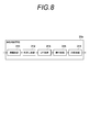
- FIG. 8 shows the configuration of the contact determination means for determining the contact state based on the integrated value of the reflected ultrasonic signal.
- the contact determination unit 31 a includes an amplification circuit 311, a folding circuit 312, an LPF circuit 313, a comparison circuit 314, and an integration circuit 315.
- the amplifier circuit 311, the folding circuit 312, and the LPF circuit 313 may be the same as those shown in FIG.
- the integration circuit 315 integrates the output signal of the LPF circuit.
- the integration circuit 315 integrates the output signal of the LPF circuit 313 for a time corresponding to the distance between the ultrasonic detection surface of the probe 11 and the surface of the probe tip that contacts the subject, for example.
- the comparison circuit 314 compares the integrated value of the reflected ultrasonic signal output from the integration circuit 315 with a voltage corresponding to the threshold value for contact determination. The comparison circuit 314 outputs a signal indicating that the probe 11 is in contact with the subject when the integral value is equal to or lower than the voltage corresponding to the threshold value.
- the contact determination unit 31 does not necessarily have to be provided in the light source unit 13.
- the contact determination unit 31 does not necessarily have to be provided in the light source unit 13.
- the contact determination unit 31 may drive the second detector element 162 to transmit an ultrasonic wave, and after transmitting the ultrasonic wave, the second detector element 162 may be switched to a reception state to detect a reflected ultrasonic wave. In this case, it is not necessary for the signal processing unit 12 to perform processing for ultrasonic transmission, and the influence of the down of the signal processing unit 12 on the contact determination processing can be further reduced.
- an AD converter analog-to-digital-converter
- contact determination processing may be performed with a digital signal in an FPGA (field programmable gate array). In that case, not only simple threshold processing but also more complicated processing such as waveform extraction becomes possible.
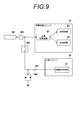
- FIG. 9 shows the circuit connection when the first detector element also serves as the second detector element.
- the transmission / reception switching circuit 21, the reception circuit 22, and the transmission circuit 23 are disposed in the signal processing unit 12, and the contact determination means 31 is disposed in the light source unit 13 (see also FIG. 1).
- the detector element 161 as the first detector element is connected to the receiving circuit 22 and the transmitting circuit 23 via the transmission / reception switching circuit 21.
- a preamplifier IC 181 is inserted between the detector element 161 and the transmission / reception switching circuit 21.
- the preamplifier IC 181 amplifies the detection signal output from the detector element 161 and outputs the amplified detection signal to the reception circuit 22.
- the preamplifier IC 181 amplifies the detection signal with a gain of about 6 dB to 9 dB, for example.
- the preamplifier IC 181 may incorporate a circuit for switching between transmission and reception. In that case, signal processing unit 1
- the second transmission / reception switching circuit 21 can be omitted.
- the preamplifier IC 181 outputs a transmission signal to the detector element 161 when a transmission signal is output from the transmission circuit 23.
- the preamplifier IC 181 for example, MAX4805 or MAX4805A manufactured by Maxim can be used.
- the signal wiring that connects the receiving circuit 22 and the preamplifier IC 181 is connected to a branch wiring that branches the signal flowing through the signal wiring to the contact determination means 31.
- a buffer (buffer amplifier) 191 is used.
- the buffer 191 amplifies the detection signal of the detector element 161 input via the branch wiring with an amplification factor of 1, for example, and outputs the amplified signal to the contact determination means 31.
- the input impedance of the buffer 191 is set sufficiently higher than the output impedance of the preamplifier. In this case, the signal can be branched to the contact determination unit 31 with little influence on the signal output from the preamplifier IC 181 to the receiving circuit 22.
- a protection switch 192 is inserted on the input side of the buffer 191.
- the protection switch 192 opens and closes the switch according to the input voltage.
- the protection switch 192 is closed when the signal voltage is low, and cuts off the signal when a signal higher than the threshold voltage, for example, a signal of 3 V or higher is applied.
- the protection switch 192 closes the circuit and inputs the reception signal to the buffer 191.
- the protection switch 192 opens the circuit when a voltage corresponding to the transmission signal is applied to the preamplifier IC 181 to prevent a high voltage from being applied to the buffer 191.
- a protection circuit (clip circuit) 193 for limiting the input signal voltage to the buffer 191 to, for example, about 2 to 3V may be inserted between the signal input line of the buffer 191 and the ground. .
- the preamplifier IC 181 and the buffer 191 are mounted on a substrate in the probe, for example.
- the detection signal of the detector element 161 is amplified by the preamplifier IC 181 and then received by the receiving circuit 22 and used for generating a photoacoustic image and a reflected ultrasonic image.
- the detection signal amplified by the preamplifier IC 181 is also input to the contact determination unit 31 via the buffer 191 and used for contact determination. That is, the detector element 161 serves as both the first detector element for image acquisition and the second detector element for contact determination.
- the signal used for contact determination is separated from the signal for image generation, and contact determination is made in the light source unit 13 that is not linked to the signal processing unit, so the signal processing unit 12 (see FIG. 1). Even if is down, the contact determination process is possible.
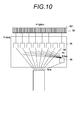
- FIG. 10 shows the connection between the acoustic wave detection means 16 having a plurality of detector elements and the preamplifier and the buffer.
- the acoustic wave detection means 16 has a plurality of detector elements 161, for example, detector elements 161 for 128 channels.
- Eight preamplifier IC blocks 18 and one buffer IC 19 are mounted on the substrate in the probe.
- the preamplifier IC block 18 in FIG. 10 corresponds to, for example, preamplifier ICs 181 for 16 channels.
- the total number of preamplifier ICs 181 is the same as the number of detector elements 161. That is, the preamplifier IC 181 is arranged corresponding to each detector element 161.
- the eight preamplifier IC blocks 18 output the detection signals of the detector elements 161 for a total of 128 channels to the receiving circuit 22 via the signal wiring 14.
- the buffer IC 19 has buffers 191 for 8 channels, for example.
- the buffer 191 is connected to the branch wiring 15 branched from a part of the plurality of signal wirings 14 connecting the eight preamplifier IC blocks 18 and the receiving circuit 22.
- 8 channels of the total 128 channels output to the receiving circuit 22 are input to the buffer IC 19.
- Buffer IC 19 inputs the detection signals of the detector elements 161 via a total of eight branch wirings 15, and outputs the detection signals of the detector elements 161 for a total of 8 channels to the contact determination means 31.
- the signal is branched from a part of the signal wiring 14 connecting the eight preamplifier IC blocks 18 and the receiving circuit 22 to the buffer IC 19, but the signal may be branched from all the signal wirings 14.
- the preamplifier IC 181 does not need to correspond to all channels, only the channel to be branched has the preamplifier IC181, and the channels that are not branched have the preamplifier IC181. It does not have to be. In that case, the difference in signal level due to the presence or absence of the preamplifier IC 181 may be corrected by the receiving circuit 22.
- the total number of buffers 181 and the number of branch wirings 15 do not necessarily match. When the total number of buffers 181 is smaller than the number of branch wirings 15, a switch for selecting a wiring connected to the buffer 191 among the branch wirings 15 is further provided between the branch wiring 15 and the buffer 191. Good.
- the photoacoustic measuring device of this invention is not limited only to the said embodiment, A various correction and change are carried out from the structure of the said embodiment. Those applied are also included in the scope of the present invention.
Landscapes
- Health & Medical Sciences (AREA)
- Life Sciences & Earth Sciences (AREA)
- Physics & Mathematics (AREA)
- General Health & Medical Sciences (AREA)
- Molecular Biology (AREA)
- Veterinary Medicine (AREA)
- Pathology (AREA)
- Public Health (AREA)
- Engineering & Computer Science (AREA)
- Biomedical Technology (AREA)
- Heart & Thoracic Surgery (AREA)
- Medical Informatics (AREA)
- Biophysics (AREA)
- Surgery (AREA)
- Animal Behavior & Ethology (AREA)
- Radiology & Medical Imaging (AREA)
- Nuclear Medicine, Radiotherapy & Molecular Imaging (AREA)
- Acoustics & Sound (AREA)
- Gynecology & Obstetrics (AREA)
- Ultra Sonic Daignosis Equipment (AREA)
Abstract
接触判断の処理を画像生成のための処理と分離して行う光音響計測装置を提供する。音響波検出手段16は、第1の検出器素子161と第2の検出器素子162とを有する。光源からの光が被検体に向けて出射した後に第1の検出器素子161によって検出された光音響信号は、信号処理ユニットによって受信され、信号処理ユニットにて画像生成などの信号処理が行われる。音響波の送信後に第2の検出器素子162によって検出された反射音響波信号は、接触判断手段31によって受信される。接触判断手段31は、受信した反射音響波信号に基づいてプローブが被検体に接触しているか否かを判断する。
Description
本発明は、光音響計測装置に関し、更に詳しくは、被検体に光を出射し、光出射により被検体内において生じた光音響波を検出する光音響計測装置に関する。
生体内部の状態を非侵襲で検査できる画像検査法の一種として、超音波検査法が知られている。超音波検査では、超音波の送信及び受信が可能な超音波探触子を用いる。超音波探触子から被検体(生体)に超音波を送信させると、その超音波は生体内部を進んでいき、組織界面において反射する。超音波探触子によりその反射超音波を受信し、反射超音波が超音波探触子に戻ってくるまでの時間に基づいて距離を計算することによって、内部の様子を画像化することができる。
また、光音響効果を利用して生体の内部を画像化する光音響イメージングが知られている。一般に光音響イメージングでは、パルスレーザ光を生体内に照射する。生体内部では、生体組織がパルスレーザ光のエネルギーを吸収し、そのエネルギーによる断熱膨張により超音波(光音響波)が発生する。この光音響波を超音波プローブなどにより検出し、その検出信号(光音響信号)に基づいて光音響画像を構成することによって、光音響波に基づく生体内の可視化が可能である。
ここで、光音響イメージングでは、比較的出力の高いレーザ光を生体内に照射する必要がある。安全性の観点からは、プローブが生体に接触していないときはパルスレーザ光の出射を抑止することが好ましい。これに関して、特許文献1には、プローブから超音波を送信し、超音波受信信号に基づいて接触が十分であるか否かを判断し、接触が十分であるときに光照射を行うことが記載されている。
特許文献1では、被検体内において反射した反射超音波は、超音波画像の生成を行う処理装置によって受信される。処理装置は、超音波画像を生成する一方で、光源の制御装置に超音波受信信号を送る。制御装置は、処理装置から受け取った超音波受信信号に基づいて接触状態を判断する。このため、超音波画像生成と接触状態の判断とを分離して行うことができず、例えば超音波画像を生成する処理装置がダウンした場合は、処理装置から超音波受信信号を受け取ることができず、接触状態の判断を行うことができない。
本発明は、上記に鑑み、画像生成などの信号処理と分離して、接触判断の処理が可能な光音響計測装置を提供することを目的とする。
上記目的を達成するために、本発明は、光源を含む光源ユニットと、音響波の検出及び音響波の送信が可能な複数の検出器素子であって、第1の検出器素子及び第2の検出器素子を含む複数の検出器素子を有する音響波検出手段と、光源から発せられた光を被検体方向へ出射する光出射部とを含むプローブと、音響波検出手段の複数の検出器素子のうちの第1の検出器素子と接続され、光源から発せられた光が被検体に出射された後に、光出射に起因して被検体内において発生し、第1の検出器素子によって検出された光音響波の検出信号を受信する受信回路と、受信回路が受信した光音響波の検出信号を信号処理する信号処理手段とを含む信号処理ユニットと、音響波検出手段の複数の検出器素子のうちの第2の検出器素子と接続され、複数の検出器素子のうちの少なくとも一部から音響波が送信された後に、第2の検出器素子によって検出された音響波の検出信号を受信し、受信した音響波の検出信号に基づいてプローブが被検体に接触しているか否かを判断する接触判断手段と、プローブが被検体に接触していると判断されたとき、光出射部から光を出射させる発光制御手段とを備えたことを特徴とする光音響計測装置を提供する。
本発明において、接触判定手段及び発光制御手段は、光源ユニットに配置されていることが好ましい。
第2の検出器素子及び接触判定手段をそれぞれ複数備え、発光制御手段は、複数の接触判定手段のうちの少なくとも1つにおいてプローブが被検体に接触していると判断されたとき、光出射部から光を出射させることも好ましい。
接触判断手段は、音響波の送信から、第2の検出器素子の音響波検出面とプローブの被検体と接触する面との間の距離に対応した時間が経過するまでの間の検出信号に基づいてプローブが被検体に接触しているか否かを判断することとしてもよい。
信号処理ユニットは、第1の検出器素子から音響波を送信させる送信回路を更に備えていてもよい。
受信回路は、第1の検出器素子から送信された音響波に対する反射音響波の検出信号を更に受信し、信号処理手段は、更に反射音響波の検出信号を信号処理することとしてもよい。
本発明では、接触判定手段は、送信回路が音響波を送信させた後、第2の検出器素子によって検出された音響波の検出信号を受信する構成を採用できる。
また、本発明では、接触判定手段は、第2の検出器素子から音響波を送信させ、音響波の送信後、第2の検出器素子によって検出された音響波の検出信号を受信する構成を採用することもできる。
音響波検出器において、第1の検出器素子及び第2の検出器素子を含む複数の検出器素子は少なくとも一次元的に配列されていてもよい。この場合、配列方向のうちの少なくとも一方の端部に第2の検出器素子が配置されている構成としてもよい。また、配列方向に沿って隣り合う2つの第1の検出器素子の間に第2の検出器素子が配置されている構成でもよい。
複数の第2の検出器素子によって検出された音響波の検出信号の和を1つの接触判定手段が受信することとしてもよい。
接触判断手段は、受信した音響波の検出信号の最大値がしきい値以下のとき、接触していると判断してもよい。
接触判断手段は、第2の検出器素子によって検出された音響波の検出信号の負の信号を正の信号に折り返す折返し回路と、折返し回路の出力信号をローパスフィルタ処理するローパスフィルタ回路と、ローパスフィルタ回路の出力信号レベルとしきい値に対応した電圧とを比較する比較回路とを含む構成とすることができる。
上記に代えて、接触判断手段は、受信した音響波の検出信号を積分し、積分値がしきい値以下のとき、接触していると判断することとしてもよい。
接触判断手段は、第2の検出器素子によって検出された音響波の検出信号の負の信号を正の信号に折り返す折返し回路と、折返し回路の出力信号をローパスフィルタ処理するローパスフィルタ回路と、ローパスフィルタ回路の出力信号を積分する積分回路と、積分回路の出力信号レベルとしきい値に対応した電圧とを比較する比較回路とを含む構成とすることができる。
本発明は、また、光源を含む光源ユニットと、音響波の検出及び音響波の送信が可能な複数の検出器素子であって、検出器素子を有する音響波検出手段と、光源から発せられた光を被検体方向へ出射する光出射部とを含むプローブと、検出器素子の検出信号を増幅するプリアンプと、検出器素子とプリアンプを介して接続され、光源から発せられた光が被検体に出射された後に、光出射に起因して被検体内において発生し、検出器素子によって検出された光音響波の検出信号を受信する受信回路と、受信回路が受信した光音響波の検出信号を信号処理する信号処理手段とを含む信号処理ユニットと、プリアンプと受信回路とを接続する配線から分岐された配線を介して検出器素子の検出信号を入力し、検出器素子の検出信号を出力する緩衝増幅器と、検出器素子と緩衝増幅器を介して接続され、検出器素子から音響波が送信された後に、検出器素子によって検出された音響波の検出信号を受信し、受信した音響波の検出信号に基づいてプローブが被検体に接触しているか否かを判断する接触判断手段と、プローブが被検体に接触していると判断されたとき、光出射部から光を出射させる発光制御手段とを備えた光音響計測装置を提供する。
上記の光音響計測装置において、プリアンプの出力インピーダンスは緩衝増幅器の入力インピーダンスよりも低いことが好ましい。
本発明の光音響計測装置では、プローブは検出器素子を複数有し、プリアンプは複数の検出器素子のそれぞれに対応して配置されており、かつ、緩衝増幅器は、プリアンプと受信回路とを接続する複数の配線のうちの少なくとも一部から分岐された配線を介して検出器素子の検出信号を入力してもよい。
本発明の光音響計測装置は、緩衝増幅器の入力側に、しきい値電圧以上の信号が印加されると信号を遮断する保護スイッチを更に有する構成とすることが好ましい。また、本発明の光音響計測装置は、緩衝増幅器の入力側に、緩衝増幅器への入力信号電圧を制限する保護回路を有することが更に好ましい。
緩衝増幅器の数は上記の分岐された配線の数よりも少なく、分岐された配線と緩衝増幅器との間に、分岐された配線のうち緩衝増幅器に接続される配線を選択するスイッチを更に備えた構成であってもよい。
本発明の光音響計測装置では、検出器素子によって検出された信号の信号経路を分離し、画像生成などの信号処理と、接触判断の処理とを連動せず分離して行うことができる。
以下、図面を参照し、本発明の実施の形態を詳細に説明する。図1は、本発明の一実施形態に係る光音響計測装置を示す。光音響計測装置10は、プローブ11、信号処理ユニット12、及び光源ユニット13を備える。光音響計測装置10は、超音波画像と光音響画像との双方を生成可能である。なお、本発明の実施形態では、音響波として超音波を用いるが、超音波に限定されるものでは無く、被検対象や測定条件等に応じて適切な周波数を選択してさえいれば、可聴周波数の音響波を用いても良い。
光源ユニット13は、被検体に向けて出射される光(レーザ光)を生成する。プローブ11は、被検体に光が出射された後に、光出射に起因して被検体内で発生した光音響波を検出する。また、被検体に対する音響波(超音波)の送信、及び送信した音響波に対する反射音響波(反射超音波)の受信を行う。信号処理ユニット12は、プローブ11で検出された光音響波の検出信号(光音響信号)に基づいて光音響画像を生成する。また、プローブ11で検出された反射超音波の検出信号(反射超音波信号)に基づいて超音波画像(反射音響波画像)を生成する。
プローブ11は、音響波検出手段16と光出射部17とを有する。音響波検出手段16は、音響波の検出及び音響波の送信が可能な複数の検出器素子を有する。複数の検出器素子は、1以上の第1の検出器素子と1以上の第2の検出器素子とを含む。第1の検出器素子は画像取得用の検出器素子であり、第2の検出器素子は接触判断用の検出器素子である。光出射部17は、光源ユニット13からの光を被検体方向へ出射する。
信号処理ユニット12は、送受切替回路21、受信回路22、送信回路23、画像生成手段24、及び送受制御回路25を有する。送受切替回路21は、超音波の送信と受信とを切り替える。送受切替回路21は、音響波検出手段16の複数の検出器素子のうちの第1の検出器素子と接続されている。送受切替回路21は、超音波の受信時は第1の検出器素子と受信回路22とを接続し、音響波の送信時は送信回路23と第1の検出器素子とを接続する。送受制御回路25は、音響波の送信と受信を制御する。
送信回路23は送信信号を生成する。送信回路23は、送受切替回路21を介して、音響波検出手段16の第1の検出器素子を送信信号を送る。音響波検出手段16の第1の検出器素子は送信信号に応じて駆動され、第1の検出器素子から超音波が送信される。受信回路22は、送受切替回路21を介して、音響波検出手段16の第1の検出器素子から出力される超音波信号を受信する。受信回路22が受信する超音波信号は、光音響信号と反射超音波信号とを含む。
画像生成手段24は、信号処理手段であり、受信回路22が受信した超音波信号に基づいて画像生成を行う。より詳細には、画像生成手段24は、光音響信号に基づいて光音響画像を生成し、反射超音波信号に基づいて超音波画像を生成する。なお、画像の生成は必須ではなく、画像生成手段24において、超音波信号に対して何らかの信号処理を施すだけでもよい。また、反射超音波に対する信号処理(画像生成)は省略してもよい。
光源ユニット13は、接触判断手段31、発光制御手段32、及び光源(発光部)33を有する。接触判断手段31は、音響波検出手段16の複数の検出器素子のうちの第2の検出器素子に接続されている。接触判断手段31は、音響波検出手段16の複数の検出器素子のうちの少なくとも一部から超音波が送信された後に、第2の検出器素子で検出された反射超音波の検出信号(反射超音波信号)を受信する。接触判断手段31は、第2の検出器素子から出力される反射超音波信号に基づいてプローブ11が被検体に接触しているか否かを判断する。
プローブ11が被検体に接触していない場合には、音響波検出手段16から超音波を送信すると、プローブ11の先端と空気との界面から強い反射超音波が返ってくる。一方、プローブ11が被検体に接触している場合、送信された超音波は、その多くがプローブ11から被検体内に侵入し、界面から強い反射超音波が返ってくることはない。接触判断手段31は、例えば第2の検出器素子から受信した反射超音波信号の最大値がしきい値よりも小さいとき、プローブ11が被検体に接触していると判断する。
上記の第2の検出器素子で検出された反射超音波信号の受信は、超音波の送信タイミングから、プローブ11における超音波検出面と被検体に接触するプローブ先端の面との間の距離に対応した時間が経過するまでの間だけ行えばよい。つまり、接触判断手段31は、超音波の送信から、第2の検出器素子の超音波検出面とプローブ11の被検体と接触する面との間の距離に対応した時間が経過するまでの間の検出信号に基づいてプローブが被検体に接触しているか否かを判断すればよい。
接触判断手段31は、例えば送信回路23から超音波を送信したことを示す信号を受け取ると、第2の検出器素子から出力される反射超音波信号をある期間だけモニタし、その期間における反射超音波信号の最大値をしきい値処理する。反射超音波信号の最大値がしきい値よりも小さいとき、プローブ11が被検体に接触していると判断する。
なお、プローブの先端にアタッチメント(超音波透過ゲル)などを取り付ける場合には、超音波検出面と被検体に接触するプローブ先端の面との間の距離が、アタッチメントの厚みの分だけ長くなる。また、使用するアタッチメントに応じて、プローブ11の先端(アタッチメントの先端)と空気との界面で発生する反射超音波の大きさも変化すると考えられる。アタッチメントを使用する場合には、使用するアタッチメントに応じて、接触判断の基準となる反射超音波信号のしきい値を適宜変更すればよい。また、使用するアタッチメントの厚み(超音波検出面側の面から被検体側の面までの間の距離)に応じて、反射超音波信号をモニタする期間を調整すればよい。
光源33は、被検体に向けて出射される光(レーザ光)を出射する。レーザ光の波長は、観察対象物に応じて適宜設定すればよい。発光制御手段32は、光源33の光出射を制御する。発光制御手段32は、接触判断手段31がプローブが被検体に接触していると判断したとき、光源33に光を出射させる。光源33から出射した光は、光ファイバなどの導光手段を用いてプローブ11まで導光され、プローブ11の光出射部17から出射される。
図2は、音響波検出手段16を示す。音響波検出手段16は、例えば1次元的に配列された複数の検出器素子を含む。配列された複数の検出器素子のうち、配列方向の両端の検出器素子を第2の検出器素子162とし、残りの検出器素子を第1の検出器素子161とする。例えば計130個の検出器素子が1次元配列されている場合は、両端である1chと130chの2つの検出器素子を接触判断用の第2の検出器素子162とし、2ch~
129chの128個の検出器素子を画像取得用の第1の検出器素子161とする。なお、第2の検出器素子162は、必ずしも検出器素子の配列方向の両端に設けられている必要はなく、どちらか片方でもよい。また、検出器素子の配列は1次元配列には限定されない。複数の検出器素子が2次元的に配列されていてもよい。
129chの128個の検出器素子を画像取得用の第1の検出器素子161とする。なお、第2の検出器素子162は、必ずしも検出器素子の配列方向の両端に設けられている必要はなく、どちらか片方でもよい。また、検出器素子の配列は1次元配列には限定されない。複数の検出器素子が2次元的に配列されていてもよい。
画像取得用である第1の検出器素子161は、送受切替回路21を介して受信回路22又は送信回路23に接続される。送受切替回路21と第1の検出器素子161との間にマルチプレクサが設けられる構成とし、128個の第1の検出器素子161のいくつかが選択的に受信回路22又は送信回路23に接続されるようにしてもよい。マルチプレクサは、例えば超音波のラインbyライン走査や、光音響画像取得時の領域選択に用いることができる。接触判断のための超音波を送信する際には、音響波検出手段16に設けられた全ての第1の検出器素子161から超音波を送信する必要はなく、その一部から送信することとしてもよい。
接触判断用である2つの第2の検出器素子162は、対応する接触判断手段31にそれぞれ接続される。各接触判断手段31は、接続された第2の検出器素子162から出力される反射超音波信号が、しきい値よりも小さいか否かを判断する。発光制御手段32(図1を参照)は、2つの接触判断手段31における判断結果に基づいて光源33の制御を行う。図2の例のように、第2の検出器素子162及び接触判断手段31を複数個有する場合、発光制御手段32は、複数の接触判断手段31のうちの少なくとも1つでプローブ11が被検体に接触していると判断されたとき、光源33から光を出射させる。発光制御手段32は、例えば2つの接触判断手段31の双方でプローブ11が被検体に接触していると判断されたときにのみ、光源33から光を出射させてもよい。
ここで、受信回路22は、送受切替回路21を介して、音響波検出手段16に設けられた第1の検出器素子及び第2の検出器素子のうち、第1の検出器素子161のみに接続され、第2の検出器素子162には接続されない。従って、第2の検出器素子162によって検出された信号が、光音響画像の生成などに用いられることはない。一方、接触判断手段31は、音響波検出手段16に設けられた第1の検出器素子及び第2の検出器素子のうち、第2の検出器素子162のみに接続され、第1の検出器素子161には接続されない。従って、第1の検出器素子162によって検出された信号が、接触判断に用いられることはない。
図3は、接触判断手段31の構成を示す。接触判断手段31は、例えば増幅回路311、折返し回路312、LPF(Low Pass Filter)回路313、及び比較回路314を有する。増幅回路311は、第2の検出器素子162(図2を参照)から出力される反射超音波信号を増幅する。第2の検出器素子162から出力される反射超音波信号が十分に大きければ増幅回路311は省いてもよい。折返し回路312は、例えばダイオードブリッジ回路を含み、増幅回路311によって増幅された反射超音波の負の信号を正の信号に変換してLPF313へ出力する。
LPF回路313は、折返し回路312の出力信号をローパスフィルタ処理し、信号の高周波成分をカットする。比較回路314は、LPF回路313の出力信号レベルと、接触判断のしきい値に対応した電圧とを比較する。比較回路314は、LPF回路313の出力信号レベルがしきい値に対応した電圧以下のとき、プローブ11が被検体に接触している旨を示す信号を出力する。これとは逆に、LPF回路313の出力信号レベルがしきい値に対応した電圧よりも高いとき、プローブ11が被検体に接触していない旨を示す信号を出力してもよい。
図4は、動作手順を示す。送受制御回路25は、超音波送信のために、送受切替回路2
1を送信回路23に接続させる。送信回路23は、送受切替回路21を介して音響波検出手段16の第1の検出器素子161(図2を参照)に送信信号を送り、第1の検出器素子161から超音波を送信させる(ステップS1)。
1を送信回路23に接続させる。送信回路23は、送受切替回路21を介して音響波検出手段16の第1の検出器素子161(図2を参照)に送信信号を送り、第1の検出器素子161から超音波を送信させる(ステップS1)。
送受制御回路25は、超音波送信後、送受切替回路21を受信回路22に接続させる。受信回路22は、送受切替回路21を介して、第1の検出器素子161から出力される反射超音波信号を受信する(ステップS2)。画像生成手段24は、受信された反射超音波信号に基づいて超音波画像を生成する(ステップS3)。光音響計測装置10は、例えばラインbyラインで超音波の送信と受信を行い、超音波画像を生成する。
光音響計測装置10は、超音波画像の取得後、光音響画像の取得に先立って、接触判断のための超音波を送信する。送受制御回路25は、超音波送信のために、送受切替回路21を送信回路23に接続させる。送信回路23は、送受切替回路21を介して第1の検出器素子161に送信信号を送り、第1の検出器素子161から超音波を送信させる(ステップS4)。超音波の送信は、音響波検出手段16に設けられた全ての第1の検出器素子161から行う必要はなく、例えば第2の検出器素子162の近傍のいくつかの第1の検出器素子161から行えばよい。
第2の検出器素子162は、ステップS4で送信された超音波に対する反射超音波を検出する(ステップS5)。接触判断手段31は、第2の検出器素子162から出力される反射超音波信号を受信し、第2の検出器素子162で強い反射超音波が検出された否かを判断する(ステップS6)。光音響計測装置10が複数の接触判断手段31を有するときは、複数の接触判断手段31のそれぞれにおいて、第2の検出器素子162で強い反射超音波が検出された否かの判断を行う。接触判断手段31は、例えば第2の検出器素子162から出力される反射超音波信号の信号レベルがしきい値以下のとき、比較回路314(図3を参照)から、プローブ11が被検体に接触していること(以下接触ありと記載する)を示すHレベルの信号を出力する。
発光制御手段32は、ステップS6において第2の検出器素子162で強い反射超音波が検出されていないと判断されたときは、プローブ11が被検体に接触していると判断して、光源33の発光を許可する。光源33は、例えば発光制御手段32からトリガ信号を入力し、レーザ発振を行ってレーザ光を出射する(ステップS7)。ステップS6において第2の検出器素子162で強い反射超音波が検出されたと判断されたときは、処理を終了する。あるいはステップS4に戻り、強い反射超音波が検出されなくなるまでステップS4からステップS6までを繰り返し実行してもよい。
光源33は、ステップS7でレーザ光を出射する際に、レーザ光の出射タイミングを信号処理ユニット12に伝える。送受制御回路25は、光音響波の受信に備えて送受切替回路21を受信回路22に接続させる。送受切替回路21の接続先の切替えは、ステップS4の超音波送信後、光源ユニット13の発光までの間の任意のタイミングで行えばよい。光源33から発せられた光が被検体に向けて出射された後、第1の検出器素子161が光音響信号を検出する(ステップS8)。
受信回路22は、光源33の発光タイミングに合わせて、第1の検出器素子161から出力される光音響信号の受信を開始する。画像生成手段24は、受信された光音響信号に基づいて光音響画像を生成する(ステップS9)。ステップS3で生成された超音波画像とステップS9で生成された光音響画像とが、図示しないディスプレイなどの画像表示手段に表示される。超音波画像と光音響画像とは、例えば位置合せした上で重ねて表示される。あるいは、超音波画像と光音響画像とを並べて表示してもよいし、両者を切り替えて表示してもよい。
本実施形態では、音響波検出手段16は、第1の検出器素子161と第2の検出器素子162とを有する。第1の検出器素子161によって検出された検出信号は信号処理ユニット12に送られ、信号処理ユニット12において画像生成などの信号処理が行われる。一方、第2の検出器素子162によって検出された検出信号は接触判断手段31に送られ、接触判断手段31にて接触判断の処理が行われる。第1の検出器素子161と第2の検出器素子162とでは、信号出力先が異なっており、信号経路を分けられている。接触判断手段31における処理は、信号処理ユニット12内での信号処理の影響を受けず、接触判断のための処理を、画像生成のための処理と連動せず分離して実施することができる。このため、例えば信号処理ユニット12がダウンしている場合でも、接触判断の処理が可能である。
なお、図2では1次元配列された複数の検出器素子のうちの両端の検出器素子を接触判断用の第2の検出器素子162としたが、これには限定されず、第2の検出器素子162が画像取得用の第1の検出器素子161の間に挿入されていてもよい。別の言い方をすれば、第2の検出器素子162は、配列方向に沿って隣接する2つの第1の検出器素子161の間に配置されていてもよい。また、第2の検出器素子162は少なくとも1つあればよく、2つには限定されない。音響波検出手段16が3つ以上の第2の検出器素子162を有することとしてもよい。
図5は、接触判断用の第2の検出器素子162を4つ有する音響波検出手段16を示す。音響波検出手段16は、例えば計132個の検出器素子を有する。そのうちの、1ch、49ch、84ch、及び132chの計4つの検出器素子が接触判断用の第2の検出器素子162であり、残り計128個は画像取得用の第1の検出器素子161である。図5では、接触判断手段31も、第2の検出器素子162と1対1に対応する形で4つ設けられている。各接触判断手段31は、例えば接触ありと判断した場合(反射超音波信号の信号レベルがしきい値(Vth)以下の場合)はHレベルの信号を出力し、プローブ11と被検体との接触なしと判断した場合(反射超音波信号の信号レベルがしきい値(Vth)よりも高い)はLレベルの信号を出力する。
図5に示すように、音響波検出手段16の両端と中央2か所に第2の検出器素子162が配置される場合は、両端のうちの少なくとも一方が被検体と接触し、かつ中央2か所のうちの少なくとも一方が被検体と接触するときに、光出射を行うようにしてもよい。例えば、1chの第2の検出器素子162に対応した接触判断手段31の出力と、132chの第2の検出器素子162に対応した接触判断手段31の出力とを、OR回路35の入力端子に接続する。両端に対応した2つの接触判断手段31の少なくとも一方で接触ありと判断されるとき、OR回路35の出力はHレベルとなる。
また、49chの第2の検出器素子162に対応した接触判断手段31の出力と、84chの第2の検出器素子162に対応した接触判断手段31の出力とを、OR回路36の入力に接続する。中央部の2つの第2の検出器素子162に対応した接触判断手段31の少なくとも一方で接触ありと判断されるとき、OR回路36の出力はHレベルになる。OR回路35の出力と、OR回路36の出力とを、AND回路37の入力に接続する。AND回路37の出力は、OR回路35の出力とOR回路36の出力とが共にHレベルのとき、Hレベルとなる。発光制御手段32(図1を参照)は、AND回路37の出力がHレベルのとき、光源33から光を出射させればよい。このようにする場合、プローブ11の超音波検出面の全体が被検体に接触していない場合でも光出射が可能となる。
図6は、第2の検出器素子162と接触判断手段31との接続の変形例を示す。第2の検出器素子162と接触判断手段31とは1対1に対応している必要はなく、複数の第2の検出器素子162と1つの接触判断手段31とを対応させてもよい。その場合、1つの接触判断手段31は、複数の第2の検出器素子162で検出された反射超音波信号の和を受信すればよい。図6の例では、音響波検出手段16の両端の第2の検出器素子162の出力を1つにまとめ、それを1つの接触判断手段31に接続している。また、中央の2つの第2の検出器素子162の出力を1つにまとめ、それを1つの接触判断手段31に接続している。
両端に対応した接触判断手段31は、両端の第2の検出器素子162の反射超音波信号の和の信号レベルが、しきい値に対応した電圧レベル以下であるか否かを判断する。このときのしきい値を、図5の場合の接触判断手段31におけるしきい値(Vth)の2倍(2×Vth)にしておく。2つの第2の検出器素子162の少なくとも一方で強い反射超音波信号が検出されていないとき、2つの第2の検出器素子162の反射超音波信号の和は2×Vthよりも低くなる。しきい値を2×Vthとした場合、接触判断手段31は、両端の第2の検出器素子162の少なくとも一方が接触していれば、接触ありと判断してHレベルの信号を出力する。中央の2つの第2の検出器素子162に対応した接触判断手段31も同様である。
上記とは逆に、2つの第2の検出器素子162の双方で強い反射超音波信号が検出されなかったときにのみ接触ありと判断したい場合には、2つの第2の検出器素子162の反射超音波信号の和と比較するしきい値を、図5の場合におけるしきい値と同じ値(Vth)とすればよい。この場合、2つの第2の検出器素子162の何れか一方が被検体から離れているとき、反射超音波信号の和はしきい値Vthよりも大きくなる。接触判断手段31は、2つの第2の検出器素子162の双方が被検体に接触し、双方とも弱い反射超音波信号しか検出されないときに、接触ありと判断してHレベルの信号を出力する。
2つの接触判断手段31の出力は、AND回路37の入力に接続される。AND回路37の出力は、双方の接触判断手段31が接触ありを示すHレベルの信号を出力するとき、Hレベルとなる。発光制御手段32が、AND回路37の出力がHレベルのとき、光源33から光を出射させればよい点は、図5の場合と同様である。
図7は、第2の検出器素子162と接触判断手段31との接続の更なる変形例を示す。更なる変形例では、4つの第2の検出器素子162に対して1つの接触判断手段31を有する。接触判断手段31は、4つの第2の検出器素子162の反射超音波信号の和を受信し、反射超音波信号の和の信号レベルが、しきい値に対応した電圧レベル以下であるか否かを判断する。しきい値を図5の場合におけるしきい値の3倍(3×Vth)とした場合、接触判断手段31は、4つのうちの何れか1つの第2の検出器素子162が被検体に接触しているときに接触ありと判断してHレベルの信号を出力する。
図7に示す更なる変形例では、反射超音波信号の和と比較するしきい値を変えることで、何個の第2の検出器素子162が被検体に接触しているときに、接触判断手段31が接触ありと判断するかを変えることができる。しきい値を2×Vthにすれば、4つのうちの2つの第2の検出器素子162が被検体に接触しているときに接触ありと判断でき、しきい値をVthにすれば、4つのうちの1つの第2の検出器素子162が被検体に接触しているときに接触ありと判断できる。
また、上記実施形態では、接触判断手段31が反射超音波をしきい値処理することで接触状態の判断を行うものとして説明したが、これには限定されない。反射超音波信号に基づく接触状態の判断には、種々の手法を用いることができ、反射超音波信号をしきい値処理することに特に限定されるわけではない。例えば、第2の検出器素子162から受信した反射超音波信号を積分し、積分値がしきい値以下のとき、接触していると判断することとしてもよい。
図8は、反射超音波信号の積分値に基づいて接触状態の判断を行う場合の接触判断手段の構成を示す。接触判断手段31aは、増幅回路311、折返し回路312、LPF回路313、比較回路314、及び積分回路315を有する。増幅回路311、折返し回路312、及びLPF回路313は、図3に示したものと同様でよい。積分回路315は、LPF回路の出力信号を積分する。積分回路315は、例えばプローブ11における超音波検出面と被検体に接触するプローブ先端の面との間の距離に対応した時間だけ、LPF回路313の出力信号を積分する。
プローブ11が被検体に接触していない場合には、音響波検出手段16から超音波を送信すると、プローブ11の先端と空気との界面から強い反射超音波が返ってくるため、反射超音波信号の積分値が大きくなる。一方、プローブ11が被検体に接触している場合、界面から強い反射超音波が返ってくることはなく、反射超音波信号の積分値は小さい。比較回路314は、積分回路315が出力する反射超音波信号の積分値と、接触判断のしきい値に対応した電圧とを比較する。比較回路314は、積分値がしきい値に対応した電圧以下のとき、プローブ11が被検体に接触している旨を示す信号を出力する。
上記実施形態では、接触判断手段31が光源ユニット13に設けられる例について説明したが、接触判断手段31は、必ずしも光源ユニット13に設けられている必要はない。接触判断に用いられる反射超音波信号の検出に用いられる検出器素子を画像取得用の検出器素子とは別に設け、接触判断のための手段を画像生成のための手段と分離することにより、画像生成のための処理と分離して、接触判断の処理を行うことができる。
上記実施形態では、第1の検出器素子161から超音波送信を行い、第2の検出器素子162で反射超音波を検出することを説明したが、これには限定されない。接触判断手段31が第2の検出器素子162を駆動して超音波を送信させ、超音波送信後、第2の検出器素子162を受信状態に切り替えて反射超音波を検出してもよい。この場合、信号処理ユニット12が超音波送信のための処理を行う必要がなく、信号処理ユニット12のダウンが、接触判断の処理に与える影響をより低減できる。
図3及び図8では、信号をアナログ信号のまま処理する例を説明したが、これには限定されない。例えば、増幅回路311の後段にAD変換器(analog to digital converter)が設けられる構成とし、例えばFPGA(field programmable gate array)内で接触判断の処理をデジタル信号で行うこととしてもよい。その場合には、単なるしきい値処理だけではなく、波形抽出などのより複雑な処理が可能となる。
上記実施形態では、第1の検出器素子と第2の検出器素子とが別個の検出器素子である例について説明したが、これには限定されず、単一の検出器素子が、第1の検出器素子と第2の検出器素子とを兼ねてもよい。図9は、第1の検出器素子が第2の検出器素子を兼ねる場合の回路接続を示す。送受切替回路21、受信回路22、及び送信回路23は信号処理ユニット12内に配置されており、接触判断手段31は光源ユニット13内に配置されている(図1も参照)。
第1の検出器素子である検出器素子161は、送受切替回路21を介して、受信回路22及び送信回路23と接続される。検出器素子161と送受切替回路21の間には、プリアンプIC181が挿入される。プリアンプIC181は、検出器素子161から出力される検出信号を増幅し、増幅した検出信号を受信回路22に出力する。プリアンプIC181は、例えば6dB~9dB程度の利得で検出信号を増幅する。プリアンプIC181には、送受信を切り替える回路が内蔵されていてもよい。その場合、信号処理ユニット1
2の送受切替回路21は省略可能である。プリアンプIC181は、送信回路23から送信信号が出力されるときは、検出器素子161に送信信号を出力する。プリアンプIC181には、例えばマキシム社製のMAX4805やMAX4805Aを用いることができる。
2の送受切替回路21は省略可能である。プリアンプIC181は、送信回路23から送信信号が出力されるときは、検出器素子161に送信信号を出力する。プリアンプIC181には、例えばマキシム社製のMAX4805やMAX4805Aを用いることができる。
受信回路22とプリアンプIC181とを接続する信号配線には、信号配線を流れる信号を接触判断手段31に分岐する分岐配線が接続される。しかし、単に信号を分岐して接触判断手段31に入力しただけでは、受信回路22で受信される信号の電圧に変動が生じる可能性がある。そこで、バッファ(緩衝増幅器)191を用いる。バッファ191は、分岐配線を介して入力した検出器素子161の検出信号を例えば増幅度1で増幅し、接触判断手段31に出力する。バッファ191の入力インピーダンスは、プリアンプの出力イピーダンスよりも十分に高く設定される。この場合、プリアンプIC181から受信回路22に出力される信号にほとんど影響を与えることなく、接触判断手段31に信号を分岐することができる。
図9では、バッファ191の入力側に、保護スイッチ192が挿入されている。保護スイッチ192は、入力電圧に応じてスイッチの開閉を行う。保護スイッチ192は、信号電圧が低いときは閉じており、しきい値電圧以上の信号、例えば3V以上の信号が印加されると信号を遮断する。保護スイッチ192は、プリアンプIC181から受信信号が出力されているとき、回路を閉じて受信信号をバッファ191に入力する。保護スイッチ192は、プリアンプIC181に対して送信信号に対応した電圧が印加されているときは回路を開き、高電圧がバッファ191に印加されることを防ぐ。バッファ191の入力側には、更に、バッファ191の信号入力線とグランドとの間に、バッファ191への入力信号電圧を例えば2~3V程度に制限する保護回路(クリップ回路)193を挿入するとよい。
プリアンプIC181、及びバッファ191は、例えばプローブ内の基板に搭載される。検出器素子161の検出信号は、プリアンプIC181で増幅された後に受信回路22によって受信され、光音響画像の生成や反射超音波画像の生成に用いられる。加えて、プリアンプIC181で増幅された検出信号はバッファ191を介して接触判断手段31にも入力され、接触判断に用いられる。つまり、検出器素子161は、画像取得用の第1の検出器素子と、接触判断用の第2の検出器素子とを兼ねる。この場合でも、接触判断に用いられる信号は、画像生成のための信号からは分離され、信号処理ユニットと連動しない光源ユニット13において接触判断されているため、信号処理ユニット12(図1を参照)がダウンしている場合でも、接触判断の処理が可能である。
図10は、複数の検出器素子を有する音響波検出手段16とプリアンプ及びバッファとの接続を示す。なお、図10では、送受信切替回路21(図9を参照)や保護スイッチ192、保護回路193などは図示を省略している。音響波検出手段16は、複数の検出器素子161、例えば128ch分の検出器素子161を有する。プローブ内の基板には、8つのプリアンプICブロック18と1つのバッファIC19とが搭載される。図10におけるプリアンプICブロック18は、例えば16ch分のプリアンプIC181に対応する。プリアンプIC181の総数は、検出器素子161の数と同じである。つまり、プリアンプIC181は、検出器素子161のそれぞれに対応して配置されている。8つのプリアンプICブロック18は、合計128ch分の検出器素子161の検出信号を信号配線14を介して受信回路22に出力する。
バッファIC19は、例えば8ch分のバッファ191を有する。バッファ191は、8つのプリアンプICブロック18と受信回路22とを接続する複数の信号配線14の一部から分岐された分岐配線15と接続される。例えば、受信回路22に出力される総数128chの信号のうちの8ch分の信号がバッファIC19に入力される。バッファIC
19は、計8本の分岐配線15を介して検出器素子161の検出信号を入力し、計8ch分の検出器素子161の検出信号を接触判断手段31に出力する。
19は、計8本の分岐配線15を介して検出器素子161の検出信号を入力し、計8ch分の検出器素子161の検出信号を接触判断手段31に出力する。
上記では、8つのプリアンプICブロック18と受信回路22とを接続する信号配線14のうちの一部からバッファIC19へ信号を分岐したが、全ての信号配線14から信号を分岐してもよい。また、一部の信号配線14から信号を分岐する場合、プリアンプIC181は全てのチャネルに対応している必要はなく、分岐するチャネルのみがプリアンプIC181を有し、分岐されないチャネルはプリアンプIC181を有していなくてもよい。その場合、プリアンプIC181の有無に起因する信号レベルの相違は、受信回路22で補正するようにしておくとよい。さらに、バッファ181の総数と分岐配線15の数とは必ずしも一致していなくてもよい。バッファ181の総数が分岐配線15の数よりも少ないときは、分岐配線15とバッファ191との間に、分岐配線15のうちバッファ191に接続される配線を選択するスイッチを更に備える構成とすればよい。
以上、本発明をその好適な実施形態に基づいて説明したが、本発明の光音響計測装置は、上記実施形態にのみ限定されるものではなく、上記実施形態の構成から種々の修正及び変更を施したものも、本発明の範囲に含まれる。
10:光音響計測装置
11:プローブ
12:信号処理ユニット
13:光源ユニット
14:信号配線
15:分岐配線
18:プリアンプICブロック
19:バッファIC
16:音響波検出手段
17:光出射部
21:送受切替回路
22:受信回路
23:送信回路
24:画像生成手段
25:送受制御回路
31:接触判断手段
32:発光制御手段
33:光源
181:プリアンプIC
191:バッファ
192:保護スイッチ
193:保護回路
311:増幅回路
312:折返し回路
313:LPF回路
314:比較回路
315:積分回路
161:第1の検出器素子
162:第2の検出器素子
11:プローブ
12:信号処理ユニット
13:光源ユニット
14:信号配線
15:分岐配線
18:プリアンプICブロック
19:バッファIC
16:音響波検出手段
17:光出射部
21:送受切替回路
22:受信回路
23:送信回路
24:画像生成手段
25:送受制御回路
31:接触判断手段
32:発光制御手段
33:光源
181:プリアンプIC
191:バッファ
192:保護スイッチ
193:保護回路
311:増幅回路
312:折返し回路
313:LPF回路
314:比較回路
315:積分回路
161:第1の検出器素子
162:第2の検出器素子
Claims (22)
- 光源を含む光源ユニットと、
音響波の検出及び音響波の送信が可能な複数の検出器素子であって、第1の検出器素子及び第2の検出器素子を含む複数の検出器素子を有する音響波検出手段と、前記光源から発せられた光を被検体方向へ出射する光出射部とを含むプローブと、
前記複数の検出器素子のうちの前記第1の検出器素子と接続され、前記光源から発せられた光が被検体に出射された後に、前記光出射に起因して被検体内において発生し、前記第1の検出器素子によって検出された光音響波の検出信号を受信する受信回路と、該受信回路が受信した光音響波の検出信号を信号処理する信号処理手段とを含む信号処理ユニットと、
前記複数の検出器素子のうちの前記第2の検出器素子と接続され、前記複数の検出器素子のうちの少なくとも一部から音響波が送信された後に、前記第2の検出器素子によって検出された音響波の検出信号を受信し、該受信した音響波の検出信号に基づいてプローブが被検体に接触しているか否かを判断する接触判断手段と、
前記プローブが被検体に接触していると判断されたとき、前記光出射部から光を出射させる発光制御手段とを備えた光音響計測装置。 - 前記接触判定手段及び前記発光制御手段は、前記光源ユニットに配置されている請求項1に記載の光音響計測装置。
- 前記第2の検出器素子及び前記接触判定手段をそれぞれ複数備え、前記発光制御手段は、前記複数の接触判定手段のうちの少なくとも1つによって前記プローブが被検体に接触していると判断されたとき、前記光出射部から光を出射させる請求項1又は2に記載の光音響計測装置。
- 前記接触判断手段は、音響波の送信から、前記第2の検出器素子の音響波検出面とプローブの被検体と接触する面との間の距離に対応した時間が経過するまでの間の検出信号に基づいてプローブが被検体に接触しているか否かを判断する請求項1から3何れか1項に記載の光音響計測装置。
- 前記信号処理ユニットは、前記第1の検出器素子から音響波を送信させる送信回路を更に備える請求項1から4何れか1項に記載の光音響計測装置。
- 前記受信回路は、前記第1の検出器素子から送信された音響波に対する反射音響波の検出信号を更に受信し、前記信号処理手段は、更に前記反射音響波の検出信号を信号処理する請求項5に記載の光音響計測装置。
- 前記接触判定手段は、前記送信回路が音響波を送信させた後、前記第2の検出器素子によって検出された音響波の検出信号を受信する請求項5又は6に記載の光音響計測装置。
- 前記接触判定手段は、前記第2の検出器素子から音響波を送信させ、該音響波の送信後、前記第2の検出器素子によって検出された音響波の検出信号を受信する請求項1から6何れか1項に記載の光音響計測装置。
- 前記複数の検出器素子は少なくとも一次元的に配列されている請求項1から8何れか1項に記載の光音響計測装置。
- 配列方向のうちの少なくとも一方の端部に前記第2の検出器素子が配置されている請求項9に記載の光音響計測装置。
- 配列方向に沿って隣り合う2つの第1の検出器素子の間に前記第2の検出器素子が配置されている請求項9又は10に記載の光音響計測装置。
- 1つの接触判定手段は、複数の第2の検出器素子によって検出された音響波の検出信号の和を受信する請求項1から11何れか1項に記載の光音響計測装置。
- 前記接触判断手段は、受信した音響波の検出信号の最大値がしきい値以下のとき、接触していると判断する請求項1から12何れか1項に記載の光音響計測装置。
- 前記接触判断手段は、前記第2の検出器素子によって検出された音響波の検出信号の負の信号を正の信号に折り返す折返し回路と、前記折返し回路の出力信号をローパスフィルタ処理するローパスフィルタ回路と、前記ローパスフィルタ回路の出力信号レベルと前記しきい値に対応した電圧とを比較する比較回路とを含む請求項13に記載の光音響計測装置。
- 前記接触判断手段は、受信した音響波の検出信号を積分し、積分値がしきい値以下のとき、接触していると判断する請求項1から12何れか1項に記載の光音響計測装置。
- 前記接触判断手段は、前記第2の検出器素子によって検出された音響波の検出信号の負の信号を正の信号に折り返す折返し回路と、前記折返し回路の出力信号をローパスフィルタ処理するローパスフィルタ回路と、前記ローパスフィルタ回路の出力信号を積分する積分回路と、前記積分回路の出力信号レベルと前記しきい値に対応した電圧とを比較する比較回路とを含む請求項15に記載の光音響計測装置。
- 光源を含む光源ユニットと、
音響波の検出及び音響波の送信が可能な複数の検出器素子であって、検出器素子を有する音響波検出手段と、前記光源から発せられた光を被検体方向へ出射する光出射部とを含むプローブと、
前記検出器素子の検出信号を増幅するプリアンプと、
前記検出器素子と前記プリアンプを介して接続され、前記光源から発せられた光が被検体に出射された後に、前記光出射に起因して被検体内において発生し、前記検出器素子によって検出された光音響波の検出信号を受信する受信回路と、該受信回路が受信した光音響波の検出信号を信号処理する信号処理手段とを含む信号処理ユニットと、
前記プリアンプと前記受信回路とを接続する配線から分岐された配線を介して前記検出器素子の検出信号を入力し、前記検出器素子の検出信号を出力する緩衝増幅器と、
前記検出器素子と前記緩衝増幅器を介して接続され、前記検出器素子から音響波が送信された後に、前記検出器素子によって検出された音響波の検出信号を受信し、該受信した音響波の検出信号に基づいてプローブが被検体に接触しているか否かを判断する接触判断手段と、
前記プローブが被検体に接触していると判断されたとき、前記光出射部から光を出射させる発光制御手段とを備えた光音響計測装置。 - 前記プリアンプの出力インピーダンスは前記緩衝増幅器の入力インピーダンスよりも低い請求項17に記載の光音響計測装置。
- 前記プローブは前記検出器素子を複数有し、前記プリアンプは前記複数の検出器素子のそれぞれに対応して配置されており、かつ、前記緩衝増幅器は、前記プリアンプと前記受信回路とを接続する複数の配線のうちの少なくとも一部から分岐された配線を介して前記検出器素子の検出信号を入力する請求項17又は18に記載の光音響計測装置。
- 前記緩衝増幅器の入力側に、しきい値電圧以上の信号が印加されると信号を遮断する保護スイッチを更に有する請求項19に記載の光音響計測装置。
- 前記緩衝増幅器の入力側に、緩衝増幅器への入力信号電圧を制限する保護回路を更に有する請求項20に記載の光音響計測装置。
- 前記緩衝増幅器の数は前記分岐された配線の数よりも少なく、前記分岐された配線と前記緩衝増幅器との間に、前記分岐された配線のうち前記緩衝増幅器に接続される配線を選択するスイッチを更に備えた請求項19から21何れか1項に記載の光音響計測装置。
Applications Claiming Priority (4)
| Application Number | Priority Date | Filing Date | Title |
|---|---|---|---|
| JP2013-063582 | 2013-03-26 | ||
| JP2013063582 | 2013-03-26 | ||
| JP2014-044718 | 2014-03-07 | ||
| JP2014044718A JP2014207970A (ja) | 2013-03-26 | 2014-03-07 | 光音響計測装置 |
Publications (1)
| Publication Number | Publication Date |
|---|---|
| WO2014156913A1 true WO2014156913A1 (ja) | 2014-10-02 |
Family
ID=51623892
Family Applications (1)
| Application Number | Title | Priority Date | Filing Date |
|---|---|---|---|
| PCT/JP2014/057648 Ceased WO2014156913A1 (ja) | 2013-03-26 | 2014-03-20 | 光音響計測装置 |
Country Status (2)
| Country | Link |
|---|---|
| JP (1) | JP2014207970A (ja) |
| WO (1) | WO2014156913A1 (ja) |
Cited By (1)
| Publication number | Priority date | Publication date | Assignee | Title |
|---|---|---|---|---|
| CN111989046A (zh) * | 2018-04-18 | 2020-11-24 | 欧姆龙健康医疗事业株式会社 | 生物声音测定装置、辅助方法和辅助程序 |
Families Citing this family (3)
| Publication number | Priority date | Publication date | Assignee | Title |
|---|---|---|---|---|
| JP6478570B2 (ja) * | 2014-11-12 | 2019-03-06 | キヤノン株式会社 | プローブ及び被検体情報取得装置 |
| FR3132203A1 (fr) * | 2022-02-01 | 2023-08-04 | Moduleus | Procédé de détection de présence d’un organe à imager |
| KR102607805B1 (ko) * | 2022-10-14 | 2023-11-29 | 주식회사 에어스메디컬 | 의료 이미지를 기반으로 하는 접촉 판단 방법 및 이를 수행하는 컴퓨터 프로그램 |
Citations (2)
| Publication number | Priority date | Publication date | Assignee | Title |
|---|---|---|---|---|
| WO2012114729A1 (ja) * | 2011-02-22 | 2012-08-30 | 富士フイルム株式会社 | 光音響画像生成装置、及び方法 |
| JP2012231979A (ja) * | 2011-05-02 | 2012-11-29 | Canon Inc | 被検体情報取得装置およびその制御方法 |
-
2014
- 2014-03-07 JP JP2014044718A patent/JP2014207970A/ja active Pending
- 2014-03-20 WO PCT/JP2014/057648 patent/WO2014156913A1/ja not_active Ceased
Patent Citations (2)
| Publication number | Priority date | Publication date | Assignee | Title |
|---|---|---|---|---|
| WO2012114729A1 (ja) * | 2011-02-22 | 2012-08-30 | 富士フイルム株式会社 | 光音響画像生成装置、及び方法 |
| JP2012231979A (ja) * | 2011-05-02 | 2012-11-29 | Canon Inc | 被検体情報取得装置およびその制御方法 |
Cited By (3)
| Publication number | Priority date | Publication date | Assignee | Title |
|---|---|---|---|---|
| CN111989046A (zh) * | 2018-04-18 | 2020-11-24 | 欧姆龙健康医疗事业株式会社 | 生物声音测定装置、辅助方法和辅助程序 |
| CN111989046B (zh) * | 2018-04-18 | 2023-02-21 | 欧姆龙健康医疗事业株式会社 | 生物声音测定装置、辅助方法和存储介质 |
| US12383221B2 (en) | 2018-04-18 | 2025-08-12 | Omron Healthcare Co., Ltd. | Biological sound measuring device, biological sound measurement support method, and biological sound measurement support program |
Also Published As
| Publication number | Publication date |
|---|---|
| JP2014207970A (ja) | 2014-11-06 |
Similar Documents
| Publication | Publication Date | Title |
|---|---|---|
| US9649034B2 (en) | Photoacoustic imaging apparatus and method for operating a photoacoustic imaging apparatus | |
| US10098547B2 (en) | Photoacoustic measurement device, photoacoustic measurement method, and probe contact determination method | |
| US20140121505A1 (en) | Photoacoustic imaging system and apparatus, and probe unit used therewith | |
| US20120165677A1 (en) | Medical imaging system and medical imaging method thereof | |
| US20160324423A1 (en) | Photoacoustic measurement apparatus and signal processing device and signal processing method for use therein | |
| JP2010167167A (ja) | 光超音波断層画像化装置および光超音波断層画像化方法 | |
| JP2012187394A (ja) | 光音響計測装置及び光音響信号検出方法 | |
| JP2014213158A (ja) | 音響波計測装置 | |
| JP5683383B2 (ja) | 光音響撮像装置およびその作動方法 | |
| WO2014156913A1 (ja) | 光音響計測装置 | |
| US11071461B2 (en) | Photoacoustic measurement device and method | |
| JP5769652B2 (ja) | 光音響計測装置および光音響計測方法 | |
| US20180341011A1 (en) | Acoustic wave image generation apparatus and acoustic wave image generation method | |
| US10028663B2 (en) | Photoacoustic measurement apparatus and probe | |
| JP6124503B2 (ja) | 被検体情報取得装置 | |
| US11103136B2 (en) | Photoacoustic measurement probe and probe unit and photoacoustic measurement apparatus including the same | |
| JP4647449B2 (ja) | 試料分析装置 | |
| JP2015173922A (ja) | 超音波診断装置及び超音波診断装置制御方法 | |
| WO2017135167A1 (ja) | 光音響画像生成システム、装置、及び方法 | |
| US20190064350A1 (en) | Ultrasonic apparatus | |
| US20200155009A1 (en) | Photoacoustic image generation apparatus | |
| JP6362666B2 (ja) | 被検体情報取得装置 | |
| JP6309077B2 (ja) | 被検体情報取得装置 | |
| WO2011161592A2 (en) | System with interventional ultrasound monitoring device | |
| WO2019044212A1 (ja) | 光音響画像生成装置および画像取得方法 |
Legal Events
| Date | Code | Title | Description |
|---|---|---|---|
| 121 | Ep: the epo has been informed by wipo that ep was designated in this application |
Ref document number: 14775012 Country of ref document: EP Kind code of ref document: A1 |
|
| NENP | Non-entry into the national phase |
Ref country code: DE |
|
| 122 | Ep: pct application non-entry in european phase |
Ref document number: 14775012 Country of ref document: EP Kind code of ref document: A1 |