WO2014156647A1 - 複数の入力画像をエンコーディングする方法、プログラムを格納する記憶媒体および装置 - Google Patents
複数の入力画像をエンコーディングする方法、プログラムを格納する記憶媒体および装置 Download PDFInfo
- Publication number
- WO2014156647A1 WO2014156647A1 PCT/JP2014/056483 JP2014056483W WO2014156647A1 WO 2014156647 A1 WO2014156647 A1 WO 2014156647A1 JP 2014056483 W JP2014056483 W JP 2014056483W WO 2014156647 A1 WO2014156647 A1 WO 2014156647A1
- Authority
- WO
- WIPO (PCT)
- Prior art keywords
- unit
- image
- remainder
- macroblock
- residual
- Prior art date
Links
Images


Classifications
-
- H—ELECTRICITY
- H04—ELECTRIC COMMUNICATION TECHNIQUE
- H04N—PICTORIAL COMMUNICATION, e.g. TELEVISION
- H04N19/00—Methods or arrangements for coding, decoding, compressing or decompressing digital video signals
- H04N19/10—Methods or arrangements for coding, decoding, compressing or decompressing digital video signals using adaptive coding
- H04N19/102—Methods or arrangements for coding, decoding, compressing or decompressing digital video signals using adaptive coding characterised by the element, parameter or selection affected or controlled by the adaptive coding
- H04N19/103—Selection of coding mode or of prediction mode
-
- H—ELECTRICITY
- H04—ELECTRIC COMMUNICATION TECHNIQUE
- H04N—PICTORIAL COMMUNICATION, e.g. TELEVISION
- H04N19/00—Methods or arrangements for coding, decoding, compressing or decompressing digital video signals
- H04N19/10—Methods or arrangements for coding, decoding, compressing or decompressing digital video signals using adaptive coding
- H04N19/134—Methods or arrangements for coding, decoding, compressing or decompressing digital video signals using adaptive coding characterised by the element, parameter or criterion affecting or controlling the adaptive coding
- H04N19/136—Incoming video signal characteristics or properties
- H04N19/14—Coding unit complexity, e.g. amount of activity or edge presence estimation
-
- H—ELECTRICITY
- H04—ELECTRIC COMMUNICATION TECHNIQUE
- H04N—PICTORIAL COMMUNICATION, e.g. TELEVISION
- H04N19/00—Methods or arrangements for coding, decoding, compressing or decompressing digital video signals
- H04N19/10—Methods or arrangements for coding, decoding, compressing or decompressing digital video signals using adaptive coding
- H04N19/169—Methods or arrangements for coding, decoding, compressing or decompressing digital video signals using adaptive coding characterised by the coding unit, i.e. the structural portion or semantic portion of the video signal being the object or the subject of the adaptive coding
- H04N19/17—Methods or arrangements for coding, decoding, compressing or decompressing digital video signals using adaptive coding characterised by the coding unit, i.e. the structural portion or semantic portion of the video signal being the object or the subject of the adaptive coding the unit being an image region, e.g. an object
- H04N19/172—Methods or arrangements for coding, decoding, compressing or decompressing digital video signals using adaptive coding characterised by the coding unit, i.e. the structural portion or semantic portion of the video signal being the object or the subject of the adaptive coding the unit being an image region, e.g. an object the region being a picture, frame or field
-
- H—ELECTRICITY
- H04—ELECTRIC COMMUNICATION TECHNIQUE
- H04N—PICTORIAL COMMUNICATION, e.g. TELEVISION
- H04N19/00—Methods or arrangements for coding, decoding, compressing or decompressing digital video signals
- H04N19/10—Methods or arrangements for coding, decoding, compressing or decompressing digital video signals using adaptive coding
- H04N19/169—Methods or arrangements for coding, decoding, compressing or decompressing digital video signals using adaptive coding characterised by the coding unit, i.e. the structural portion or semantic portion of the video signal being the object or the subject of the adaptive coding
- H04N19/17—Methods or arrangements for coding, decoding, compressing or decompressing digital video signals using adaptive coding characterised by the coding unit, i.e. the structural portion or semantic portion of the video signal being the object or the subject of the adaptive coding the unit being an image region, e.g. an object
- H04N19/176—Methods or arrangements for coding, decoding, compressing or decompressing digital video signals using adaptive coding characterised by the coding unit, i.e. the structural portion or semantic portion of the video signal being the object or the subject of the adaptive coding the unit being an image region, e.g. an object the region being a block, e.g. a macroblock
-
- H—ELECTRICITY
- H04—ELECTRIC COMMUNICATION TECHNIQUE
- H04N—PICTORIAL COMMUNICATION, e.g. TELEVISION
- H04N19/00—Methods or arrangements for coding, decoding, compressing or decompressing digital video signals
- H04N19/10—Methods or arrangements for coding, decoding, compressing or decompressing digital video signals using adaptive coding
- H04N19/169—Methods or arrangements for coding, decoding, compressing or decompressing digital video signals using adaptive coding characterised by the coding unit, i.e. the structural portion or semantic portion of the video signal being the object or the subject of the adaptive coding
- H04N19/182—Methods or arrangements for coding, decoding, compressing or decompressing digital video signals using adaptive coding characterised by the coding unit, i.e. the structural portion or semantic portion of the video signal being the object or the subject of the adaptive coding the unit being a pixel
-
- H—ELECTRICITY
- H04—ELECTRIC COMMUNICATION TECHNIQUE
- H04N—PICTORIAL COMMUNICATION, e.g. TELEVISION
- H04N19/00—Methods or arrangements for coding, decoding, compressing or decompressing digital video signals
- H04N19/46—Embedding additional information in the video signal during the compression process
Definitions
- the present invention relates to a method for encoding a plurality of input images including information related to each other, a storage medium for storing a program, and a device.
- Non-Patent Document 1 a video coding method that considers redundancy between frames for a moving image composed of a sequence of frames arranged in the time domain.
- a P frame predicted frame
- / or a B frame bi-directional predicted frame
- the P frame is a frame calculated by forward prediction
- the B frame is a frame calculated by any one of forward prediction, backward prediction, and bidirectional prediction.
- Non-Patent Document 2 discloses a method of applying such video encoding technology to the time domain and the spatial domain. That is, according to the teaching content of Non-Patent Document 2, P frames and / or B frames can be generated for a plurality of frames arranged in the time domain and the spatial domain.
- a frame sequence used in 3D video technology that provides high-definition stereoscopic video using multi-viewpoint images can be given.
- Such a stereoscopic image is realized by a multi-viewpoint image obtained by imaging a subject from a very large number of viewpoints (for example, 200 viewpoints).
- viewpoint interpolation such as generating a P frame and / or a B frame using three-dimensional information such as a distance map It can also be applied to.
- encoding compressing (converting) data into a code according to the purpose
- decoding decoding
- coding shall mean encoding alone and both encoding and decoding.
- the generated P frame and B frame are transmitted in the form of a residual value.
- a data compression process is further performed on the residual information.
- image conversion typically, discrete cosine conversion
- quantization quantization
- entropy coding and the like are executed.
- the data compression rate is high, performing the quantization causes a significant loss of data due to the data size reduction. That is, residual information having a small value is lost by the data compression process.
- edge information and boundary information must be prevented from being lost even if the data compression rate is increased.
- a method for encoding a plurality of input images including information related to each other includes a step of estimating a motion image indicating a change component included in a subsequent input image from one or more previous input images, and a residual image from a difference between the subsequent input image and the motion image. Generating a region based on the pixel value of the residual image, identifying a region in which the pixel value of the residual image is to be defined with a remainder, and specifying the identified residual.
- the method includes a step of converting a pixel value of a region into a remainder, and a step of encoding a converted residual image and additional information for specifying a region to be defined by the remainder.
- the method further includes a step of decoding the residual image by performing an inverse modulo operation on a pixel defined by the remainder among the pixels constituting the converted residual image, and the estimating step further includes: Estimating a motion image based on the decoded residual image.
- the specifying step includes a step of determining an area to be defined by the remainder on a pixel basis based on a pixel value of each pixel constituting the residual image, and the additional information includes the residual image.
- the constituent pixels information for specifying each pixel defined by the remainder is included.
- an area to be defined by a remainder is determined based on a result of combining evaluations of pixel values of respective pixels constituting the block.
- the additional information includes information for specifying a block defined by the remainder among the blocks included in the residual image.
- the converting step includes a step of executing a modulo operation on a pixel value for a region to be defined by a remainder, a step of acquiring gradient information of a motion image, and a value that is a method of gradient strength and modulo operation. And determining a value to be a modulo arithmetic method based on the obtained gradient information.
- the additional information includes a criterion for specifying an area in which the pixel value is to be defined as a remainder among pixels constituting the residual image.
- a storage medium for storing a program for encoding a plurality of input images including information related to each other.
- the program causes a computer to estimate a motion image indicating a change component included in a subsequent input image from one or more previous input images, and a difference between the motion image estimated from the subsequent input image.
- a step of converting a pixel value of a region to be defined into a remainder, and a step of encoding the converted residual image and additional information for specifying the region to be defined as a residue are executed.
- an apparatus for encoding a plurality of input images including information related to each other includes a means for estimating a motion image indicating a change component included in a subsequent input image from one or more previous input images, and a residual image from a difference between the subsequent input image and the motion image. Based on the pixel value of the residual image, means for specifying a region in which the pixel value of the residual image should be defined by the remainder, and the specified residual should be defined Means for converting the pixel value of the region into a remainder, and means for encoding the converted residual image and additional information for specifying the region to be defined by the remainder.
- FIG. 1 is a diagram showing a stereoscopic video reproduction system including an encoding / decoding system according to an embodiment of the present invention. It is a functional block diagram of the encoder which concerns on the related technique of this invention. It is a functional block diagram of the decoder which concerns on the related technique of this invention. It is a functional block diagram of the encoder which concerns on embodiment of this invention. It is a figure for demonstrating the combination method of the remainder and residual which concerns on embodiment of this invention. It is a functional block diagram of the data format conversion part which concerns on embodiment of this invention. It is a figure which shows an example of the Lookup table for determining the coefficient used for calculation of the remainder which concerns on embodiment of this invention.
- FIG. 1 is a diagram showing a stereoscopic video reproduction system 1 including an encoding / decoding system according to an embodiment of the present invention.
- a multi-viewpoint image is generated by imaging a subject 2 using a camera array including a plurality of cameras 10.
- the multi-viewpoint image corresponds to an image group obtained by capturing the subject 2 from a plurality of viewpoints.
- the multi-viewpoint image is transmitted after being encoded by the information processing apparatus 100 functioning as a transmitter.
- the data generated by encoding in the information processing apparatus 200 functioning as a receiver is decoded, and the subject 2 is reproduced in the stereoscopic display apparatus 300. That is, the stereoscopic display device 300 displays a stereoscopic image of the subject 2.
- any medium can be used regardless of wired or wireless.
- the information processing apparatus 100 that functions as a transmitter includes a preprocessor 110 that performs preprocessing on an input image and an encoder 120 that performs encoding.
- Encoding executed in the information processing apparatus 100 includes data format conversion and data compression processing, as will be described later. That is, the encoder according to the embodiment of the present invention performs data format conversion and data compression in parallel.
- the information processing apparatus 200 that functions as a receiver includes a decoder 210 that performs decoding on received data and a post processor 220 that performs post-processing.
- Decoding executed in the information processing apparatus 200 includes data format reverse conversion and data restoration processing, as will be described later. That is, the decoder according to the embodiment of the present invention performs data format inverse conversion and data restoration in parallel.
- the stereoscopic display device 300 includes a display screen 310 mainly including a diffusion film 312 and a condenser lens 314, and a projector array 302 that projects a multi-viewpoint image on the display screen 310.
- Each projector constituting the projector array 302 projects a viewpoint image corresponding to the multi-viewpoint image output from the information processing apparatus 200 onto the display screen 310.
- a reproduced stereoscopic image of the subject 2 is provided to an observer in front of the display screen 310.
- the viewpoint image entering the visual field of the observer changes according to the relative position between the display screen 310 and the observer, and the observer is as if in front of the subject 2.
- Such a stereoscopic video reproduction system 1 is used in a movie theater or an amusement facility as a general use, and is used as an electronic advertisement system such as a telemedicine system, an industrial design design system, or public viewing as an industrial use. It is expected that
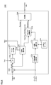
- FIG. 2 is a functional block diagram of the encoder 820 according to the related technology of the present invention.
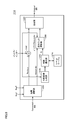
- FIG. 3 is a functional block diagram of the decoder 910 according to the related art of the present invention.
- each frame of the video signal that is a moving image (that is, a frame sequence arranged in the time domain) from the input source is divided into a plurality of macroblocks (Macroblocks).
- Intraframe prediction is a method of interpolating a target macroblock from other macroblocks in the same frame.
- interframe prediction is a method of interpolating a target macroblock from information of another frame using any one of forward prediction, backward prediction, and bidirectional prediction.
- the encoder 820 performs data compression by paying attention to the relationship (that is, redundancy) with the information of the same or similar frames.
- the encoder 820 includes an input buffer 8202, a division unit 8204, a subtraction unit 8206, an orthogonal transformation / quantization unit 8208, a local decoder 8210, a control unit 8230, a motion estimation unit 8240, An output buffer 8242 and an entropy encoding unit 8250 are included.
- the input buffer 8202 temporarily stores the video signal from the input source.
- the dividing unit 8204 divides the video signal stored in the input buffer 8202 into a plurality of macro blocks (N ⁇ N pixels). The output from the dividing unit 8204 is given to the subtracting unit 8206, the control unit 8230, and the motion estimation unit 8240.
- the subtraction unit 8206 calculates residual information by subtracting the previously calculated interpolation information (intraframe prediction or interframe prediction) for each macroblock from the division unit 8204. That is, the subtraction unit 8206 generates a residual image by subtracting the predicted image from the original image. This residual image generation processing is typically executed in units of macroblocks.
- the orthogonal transform / quantization unit 8208 performs orthogonal transform (typically, discrete Fourier transform) and quantization on the residual image from the subtraction unit 8206.
- the orthogonal transform / quantization unit 8208 also performs scaling.
- the quantized transform coefficient from orthogonal transform / quantization unit 8208 is output to local decoder 8210 and entropy coding unit 8250.
- the local decoder 8210 calculates interpolation information for the subsequent frame (the macroblock). More specifically, local decoder 8210 includes an inverse orthogonal transform / scaling unit 8212, an adding unit 8214, a deblocking filter 8216, an intra frame prediction unit 8218, a motion compensation unit 8220, and a switching unit 8222. .
- the inverse orthogonal transform / scaling unit 8212 performs inverse orthogonal transform and scaling on the transform coefficient after quantization from the orthogonal transform / quantization unit 8208. That is, the inverse orthogonal transform / scaling unit 8212 restores the residual image output from the subtracting unit 8206.
- the adding unit 8214 adds the residual image from the inverse orthogonal transform / scaling unit 8212 and the predicted image (interpolation information) calculated in advance.
- the deblocking filter 8216 smoothes the block boundary with respect to the addition result from the adding unit 8214 in order to suppress the occurrence of block noise.
- the original image given from the input buffer 8202 is restored by the inverse orthogonal transform / scaling unit 8212, the adding unit 8214, and the deblocking filter 8216. Then, the information of the restored original image is given to the intra frame prediction unit 8218 and the motion compensation unit 8220.
- the intra frame prediction unit 8218 generates a prediction image based on adjacent macroblocks.
- the motion compensation unit 8220 generates a predicted image using inter-frame prediction (inter-frame prediction). More specifically, the motion compensation unit 8220 generates a predicted image based on the restored original image and the motion data from the motion estimation unit 8240.
- One of the predicted images generated by each of the intra frame prediction unit 8218 and the motion compensation unit 8220 is appropriately selected by the switching unit 8222, and is supplied to the subtraction unit 8206.
- the motion estimation unit 8240 calculates motion data (typically a motion vector) based on each macro block from the division unit 8204 and information on the restored original image.
- the calculated motion data is output to the motion compensation unit 8220 and the entropy encoding unit 8250.
- the control unit 8230 controls processing in the orthogonal transform / quantization unit 8208, the inverse orthogonal transform / scaling unit 8212, the switching unit 8222, and the motion estimation unit 8240. In addition, the control unit 8230 instructs, as control data, parameters related to encoding, an encoding order for each component, and the like.
- the entropy encoding unit 8250 performs entropy encoding on the transform coefficient after quantization from the orthogonal transform / quantization unit 8208, the motion data from the motion compensation unit 8220, and the control data from the control unit 8230. As a result, a bit stream is output. This output bit stream is the encoding result for the input video signal.
- the output buffer 8242 is not an essential component, but temporarily stores the restored original image (video signal) from the deblock filter 8216.
- the decoder 910 shown in FIG. 3 the original image is restored from the bit stream from the encoder 820 shown in FIG.
- the encoding is inversely converted by the encoder 820 shown in FIG.
- the decoder 910 includes an input buffer 9102, an entropy decoding unit 9104, an inverse orthogonal transform / scaling unit 9112, an adding unit 9114, a deblocking filter 9116, an intra frame prediction unit 9118, and motion compensation.
- the input buffer 9102 temporarily stores the bit stream from the encoder 820.
- the entropy decoding unit 9104 performs entropy decoding on the bit stream from the input buffer 9102, and outputs motion data, quantized transform coefficients, and control data as a result.
- the inverse orthogonal transform / scaling unit 9112 performs inverse orthogonal transform (typically, discrete Fourier inverse transform) and scaling for the quantized transform coefficient decoded by the entropy decoding unit 9104. By these processes, the residual image is restored.
- inverse orthogonal transform typically, discrete Fourier inverse transform
- the addition unit 9114 adds the residual image from the inverse orthogonal transform / scaling unit 9112 and the previously calculated prediction image (interpolation information).
- the deblocking filter 9116 smoothes the block boundary with respect to the addition result from the adding unit 9114 in order to suppress the occurrence of block noise.
- the intra frame prediction unit 9118 generates a prediction image based on adjacent macroblocks.
- the motion compensation unit 9120 generates a predicted image using inter-frame prediction (inter-frame prediction). More specifically, the motion compensation unit 9120 generates a prediction image based on the restored original image and the motion data decoded by the entropy decoding unit 9104.
- One of the predicted images generated by each of the intra frame prediction unit 9118 and the motion compensation unit 9120 is appropriately selected by the switching unit 9122 and is supplied to the addition unit 9114.
- Control unit 9130 controls processing in inverse orthogonal transform / scaling unit 9112 and switching unit 9122 based on the control data decoded by entropy decoding unit 9104.
- the output buffer 9142 temporarily stores the restored original image (video signal) from the deblock filter 9116.
- MPEG-4 AVC which is one of the compression standards for moving images
- moving images are transmitted in a compressed state by the encoding / decoding system as described above.
- the encoding / decoding system includes a data format conversion process that can be incorporated into an existing standard as described above.
- the concept of a residual image is introduced to further increase data compression efficiency.
- the embodiment of the present invention not only the residual used in the existing standard but also the remainder can be used to increase the efficiency of data compression and improve the quality.
- the encoding / decoding system according to the embodiment of the present invention can be applied to an arbitrary video signal composed of a plurality of frames arranged in the time domain and / or the spatial domain. That is, the encoding / decoding system according to the embodiment of the present invention targets a plurality of input images including information related temporally and / or spatially.
- a plurality of moving images (arranged in the time domain and the spatial domain) (3) moving images generated by continuously capturing the subject with a single camera (arranged in the time domain), and (4) a stereo camera Brightness information and distance image (placed in a spatial region) generated by imaging the subject by (5), and (5) moving image (luminance information and distance image) generated by continuously imaging the subject with a stereo camera ( And the like in the time domain and the spatial domain).
- each pixel value is defined by a residual corresponding to the difference between the original image and the predicted image.
- the data format is adopted.
- each pixel value is defined by “remainder”
- This remainder is defined as a remainder (integer value) obtained by dividing a calculated value by a predetermined integer value.
- the quotient is also an integer. More specifically, the remainder is calculated by a modulo operation. The remainder calculation procedure will be described in detail later.
- a data format defined only by a residue instead of a residual or a data format defined by combining a residue and a residual can be adopted.
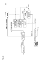
- FIG. 4 is a functional block diagram of encoder 120 according to the embodiment of the present invention.
- encoder 120 includes an input buffer 1202, a dividing unit 1204, a data format conversion unit 1206, an orthogonal transformation / quantization unit 1208, a local decoder 1210, a control unit 1230, and a motion estimation unit. 1240, an output buffer 1242, and an entropy encoding unit 1250.
- the local decoder 1210 includes an inverse orthogonal transform / scaling unit 1212, a data format inverse transform unit 1214, a deblock filter 1216, an intra frame prediction unit 1218, a motion compensation unit 1220, and a switching unit 1222.
- the encoder 120 is provided with a data format conversion unit 1206 instead of the subtraction unit 8206 that generates a residual image, as compared with the encoder 820 shown in FIG. 2, and an addition unit 8214 for restoring the original image.
- the main difference is that a data format reverse conversion unit 1214 is provided.
- the operation of the control unit 1230 is also different from that of the control unit 8230.
- the functions of the input buffer 1202, the division unit 1204, the orthogonal transformation / quantization unit 1208, the motion estimation unit 1240, the output buffer 1242, and the entropy encoding unit 1250 are the same as the input buffer 8202, the division unit 8204,
- the orthogonal transformation / quantization unit 8208, the motion estimation unit 8240, the output buffer 8242, and the entropy encoding unit 8250 are similar.
- the functions of the inverse orthogonal transform / scaling unit 1212, the deblock filter 1216, the intra frame prediction unit 1218, the motion compensation unit 1220, and the switching unit 1222 of the local decoder 1210 are the same as the inverse orthogonal transform of the local decoder 8210 shown in FIG.
- a scaling unit 8212, a deblock filter 8216, an intra frame prediction unit 8218, a motion compensation unit 8220, and a switching unit 8222 are similar.
- the video signal from the input source is applied to input buffer 1202.
- a multi-viewpoint image captured by a plurality of cameras 10 (camera array), a multi-viewpoint distance image output from a plurality of Depth cameras, a series of still images or still images, and an image of an arbitrary format Contains data.
- These video signals are temporarily stored in the input buffer 1202, and all or part of them are given to the dividing unit 1204 as input data.
- a frame sequence that is, a moving image captured by a single camera, a multi-view still image, etc.
- a frame sequence that is, a moving image captured by a single camera, a multi-view still image, etc.
- the present invention can be similarly applied to frame sequences arranged in both the time domain and the spatial domain.
- interpolation information is calculated for each frame (or macroblock) in consideration of the relevance in each of the time domain and the spatial domain.
- the dividing unit 1204 divides the video signal (input data) output from the input buffer 1202 into a plurality of macroblocks (N ⁇ N pixels). This speeds up the process of generating a predicted image by using a partial image of an appropriate size as a processing unit. However, one frame may be processed as it is without being divided into macroblocks in consideration of the computing capability of the information processing apparatus and the required processing time. Each divided macroblock is given to the data format conversion unit 1206.
- the data format conversion unit 1206 performs data format conversion using the macroblock from the division unit 1204 and the motion compensation macroblock from the intra frame prediction unit 1218 or the motion compensation unit 1220.
- the motion compensation macroblock corresponds to a motion image indicating a change component included in the subsequent input image from one or more previous input images
- the intra frame prediction unit 1218 or the motion compensation unit 1220 includes: This motion image is estimated.
- the data format conversion unit 1206 generates a residual image from the difference between the subsequent input image and the estimated motion image. Then, based on the pixel value of the residual image, the data format conversion unit 1206 identifies an area in which the pixel value is to be defined with a remainder among the pixels constituting the residual image.
- the data format conversion unit 1206 converts the pixel value for the area to be defined by the specified remainder into a remainder. By such a procedure, the converted residual image is output as an image after data format conversion.
- the corresponding motion compensation macroblock provided from the intra frame prediction unit 1218 or the motion compensation unit 1220 is used as side information for reconstructing the original macroblock from the macroblock generated by the data format conversion unit 1206. Is done.
- the macroblock after the data format conversion is given to the orthogonal transform / quantization unit 1208.
- the orthogonal transform / quantization unit 1208 further optimizes the input macroblock after data format conversion by executing orthogonal transform, quantization, and scaling. Typically, discrete Fourier transform is adopted as the orthogonal transform.
- the quantization table used in quantization and the scaling coefficient used in scaling may be optimized according to the data format type (type).
- the quantized transform coefficient from the orthogonal transform / quantization unit 8208 is output to the local decoder 1210 (inverse orthogonal transform / scaling unit 1212) and the entropy coding unit 1250.
- the inverse orthogonal transform / scaling unit 1212 performs inverse orthogonal transform and scaling on the transform coefficient after quantization from the orthogonal transform / quantization unit 1208. That is, the inverse orthogonal transform / scaling unit 1212 performs a process reverse to the transform process in the orthogonal transform / quantization unit 1208 to restore the macroblock after the data format conversion. Further, the data format inverse conversion unit 1214 performs data format inverse conversion on the restored macro block after the data format conversion, and restores each divided macro block.
- the deblocking filter 1216 smoothes the block boundary for the restored macroblock from the data format inverse conversion unit 1214 in order to suppress the occurrence of block noise.
- the original image given from the input buffer 1202 is restored by the inverse orthogonal transform / scaling unit 1212, the data format inverse transform unit 1214, and the deblock filter 1216. Then, the restored original image is provided to the intra frame prediction unit 1218 and the motion compensation unit 1220.
- the intra frame prediction unit 1218 generates a prediction image (hereinafter also referred to as “intra macro block”) based on adjacent macro blocks.
- the motion compensation unit 1220 generates a predicted image (hereinafter also referred to as “inter macroblock”) using interframe prediction (interframe prediction). These predicted images become motion compensation macroblocks.
- the motion estimation unit 1240 calculates motion data (typically a motion vector) based on each macroblock from the division unit 1204 and the restored original image. The calculated motion data is output to the motion compensation unit 1220 and the entropy encoding unit 1250.
- the control unit 1230 controls processing in the data format conversion unit 1206, orthogonal transform / quantization unit 1208, inverse orthogonal transform / scaling unit 1212, data format inverse transform unit 1214, switching unit 8222, and motion estimation unit 8240. Also, the control unit 1230 outputs, as control data, parameters related to encoding, the encoding order for each component, and the like. Further, the control unit 1230 outputs parameters (data format type (type), threshold value, flags (flag1, flag2), etc.) related to the data format conversion to the entropy encoding unit 1250.
- parameters data format type (type), threshold value, flags (flag1, flag2), etc.
- the entropy encoding unit 1250 encodes the converted residual image and additional information for specifying an area to be defined by the remainder. More specifically, the entropy coding unit 1250 performs the transform coefficient after quantization from the orthogonal transform / quantization unit 1208, the motion data from the motion estimation unit 1240, and the control data and parameters from the control unit 1230. Then, entropy encoding is performed, and as a result, a bit stream is output. This output bit stream is the encoding result for the input video signal.
- the output buffer 1242 is not an essential component, but temporarily stores the original image (video signal) restored from the deblock filter 1216.
- FIG. 5 is a diagram for explaining a method of combining the residue and the residual according to the embodiment of the present invention.
- FIG. 5A shows a technique for combining a residue and a residual in units of pixels
- FIG. 5B shows a technique of combining a remainder and a residual in units of macroblocks.
- “Rem” indicates a remainder
- “Res” indicates a residual.
- each frame is divided into a plurality of macro blocks and processed.
- a predetermined determination criterion typically a threshold value TH1 as will be described later
- TH1 a threshold value
- a predetermined judgment criterion (typically thresholds TH1 and TH2 as will be described later) is applied to each of a plurality of macroblocks constituting a frame, and a remainder is obtained. It is determined whether to use (residual macroblock) or residual (residual macroblock).
- the pixel value is calculated using a modulo operation as described later.
- the data format conversion unit 1206 calculates the difference between the original macroblock and the motion compensation macroblock (the intra macroblock generated by the intraframe prediction unit 1218 or the inter macroblock generated by the motion compensation unit 1220) in the same frame. Data format conversion is executed for (that is, the residual image). For the area defined by the remainder, the motion compensation macroblock is also used as side information.
- the pseudo gradient macroblock about a motion compensation macroblock (intra macroblock or an inter macroblock), or the macroblock which has the information similar to it Is generated.
- the gradient information may be calculated in units of frames.
- first data format a data format that combines the residue and the residue in pixel units
- second data a data format
- first data format a data format that combines the residue and the residue in pixel units
- second data a data format that combines the residue and the residue in macroblock units.
- FIG. 6 is a functional block diagram of the data format conversion unit 1206 according to the embodiment of the present invention.
- the data format conversion unit 1206 includes a subtraction unit 1260, a comparison unit 1262, a mask generation unit 1264, a process selection unit 1266, a gradient image generation unit 1270, a coefficient selection unit 1272, a Lookup.
- a table 1274, a modulo operation unit 1278, and a synthesis unit 1280 are included.
- the subtracting unit 1260 uses a motion compensation macroblock (intra macroblock or inter macroblock) from an original macroblock (indicated as “Original MB” in FIG. 6) input from the dividing unit 1204 (FIG. 4). ) (Indicated as “Inter / Intra MB” in FIG. 6) is subtracted to generate a residual macroblock (indicated as “Res MB” in FIG. 6).
- a motion compensation macroblock Intra macroblock or inter macroblock
- the comparison unit 1262 and the mask generation unit 1264 identify the pixels defined by the residual in the target macroblock. That is, the comparison unit 1262 determines an area to be defined by the remainder on a pixel basis based on the size of the pixel value of each pixel constituting the residual image (residual macroblock).
- the mask generation unit 1264 outputs, as additional information, information for specifying each pixel defined by the remainder among the pixels constituting the residual image.
- the comparison unit 1262 compares the pixel value of each pixel constituting the target macroblock with the threshold value TH1 that is part of the side information.
- the mask generation unit 1264 determines that a pixel whose pixel value is less than the threshold value TH1 should be defined as a remainder, and determines that other pixels should be defined as a residual. That is, in the residual macroblock, information of an area having a small pixel value may be largely lost, so that data compression is performed after conversion to a data format defined by a remainder instead of a residual.
- the mask generation unit 1264 generates a mask (map) in which the value of the flag flag1 for each pixel is expanded in the target frame, outputs the mask (map) to the process selection unit 1266, and outputs it to the control unit 1230. Based on the value of the flag flag1 from the mask generation unit 1264, a procedure to be applied to each pixel is determined in encoding and decoding.
- the process selection unit 1266 selects a process for each pixel constituting the target macroblock based on the value of the flag flag1. Specifically, the process selection unit 1266 outputs the pixel value of the pixel determined to be defined by the residual (indicated as “Residual” in FIG. 6) to the synthesis unit 1280 as it is. On the other hand, for the pixel determined to be defined by the remainder (indicated as “Remainder” in FIG. 6), the pixel value is output to the modulo arithmetic unit 1278.
- the modulo operation unit 1278 performs a modulo operation on the pixel value for the area to be defined by the remainder. More specifically, the modulo calculation unit 1278 performs a modulo calculation using the coefficient D (integer) set by the coefficient selection unit 1272 as a denominator to calculate a remainder. The calculated remainder is output to the synthesis unit 1280. The combining unit 1280 combines the remainder or residual input for each pixel, and outputs a macroblock after data format conversion (indicated as “Converted MB” in FIG. 6).
- the data format conversion unit 1206 may dynamically change the coefficient (denominator) D used for the modulo calculation in the modulo calculation unit 1278 based on the motion compensation macroblock.
- a region having a large pixel value in a motion compensation macroblock means a region having relatively low redundancy between frames, and the information contained in such a region is maintained even after data format conversion. It is preferable. Therefore, an appropriate coefficient D is selected according to the degree of redundancy between frames.
- FIG. 6 shows a processing example in which gradient information of a motion compensation macroblock (motion image) is acquired and a value that is a modulo arithmetic method is determined based on the acquired gradient information. More specifically, a pseudo-gradient macroblock (gradient-like macro-block) is generated for the motion compensation macroblock, and a modulus that is modulo depending on the size of the pixel value in each pixel of the pseudogradient macroblock. D is determined.
- a pseudo-gradient macroblock gradient-like macro-block
- the gradient image generation unit 1270 generates a pseudo gradient macroblock for the motion compensation macroblock. Then, a value that becomes the modulus of the modulo calculation may be determined with reference to a predetermined correspondence relationship between the gradient strength and the value that becomes the modulus of the modulo calculation. More specifically, the coefficient selection unit 1272 determines the coefficient D for each pixel by referring to the Lookup table 1274 based on the pixel value (gradient strength) of each pixel of the generated pseudo gradient macroblock. To do. By using the Lookup table 1274, the coefficient D can be determined nonlinearly with respect to the pseudo gradient macroblock. Thus, by determining the coefficient D nonlinearly, the image quality after decoding can be improved.
- FIG. 7 is a diagram showing an example of the Lookup table 1274 for determining the coefficient D used for calculating the remainder according to the embodiment of the present invention. As shown in FIG. 7, it is discretized into a plurality of stages (Gradient Range) according to the gradient strength, and a coefficient D for each stage is defined.
- the gradient image generation unit 1270 refers to the Lookup table 1274 and selects a coefficient D corresponding to each pixel of the target macroblock. Here, the coefficient D is determined for each pixel of each color component included in the target macroblock.
- the Lookup table 1274 shown in FIG. 7 is designed so that a value (coefficient D) used as a modulo arithmetic method is a power of two. By assigning the coefficient D in this way, the modulo operation can be speeded up. Since the Lookup table 1274 can be designed arbitrarily, the number of stages may be smaller, or the Lookup table with more stages may be adopted.
- the Lookup table is not necessarily used, and the coefficient D may be determined using a predetermined function or the like.
- the pixel value in each pixel of the pseudo gradient macroblock may be used as the coefficient D as it is.
- q is a quotient and m is a remainder.
- pixel value P k ⁇ D + m” is calculated, so that a remainder m (Remainder) for each color component calculated for each pixel is output.
- the gradient image generation unit 1270 generates a pseudo gradient macroblock indicating the degree of change in the image space from a motion compensation macroblock (intra macroblock or inter macroblock) as side information.
- the pseudo gradient macroblock means an image in which a region having a larger texture change has a higher luminance in the motion compensation macroblock.
- Arbitrary filtering processing can be used as generation processing of the pseudo gradient macroblock.
- Each pixel value constituting the pseudo gradient macroblock is normalized so as to take any integer value within a predetermined range (for example, 0 to 255).
- a pseudo gradient macroblock is generated by the following processing procedure.
- the processing procedure shown here is an example, and the processing content and processing procedure of Gaussian smoothing processing and morphological processing can be designed as appropriate.
- any method may be adopted as long as a macroblock that assigns a larger pixel value (luminance) to a region where a larger luminance change occurs in the motion compensation macroblock can be generated.
- a sobel filter may be applied to each of the x direction and the y direction, and the average value of the application results may be a macroblock.
- FIG. 8 is another functional block diagram of data format conversion unit 1206 according to the embodiment of the present invention.
- data format conversion unit 1206 is different from data format conversion unit 1206 shown in FIG. 6 in place of mask generation unit 1264, process selection unit 1266, and synthesis unit 1280, integrating unit 1265, An evaluation unit 1267 and a switching unit 1269 are provided. Since the details of the other components have been described above, their contents will not be repeated.
- the comparison unit 1262, the integration unit 1265, and the evaluation unit 1267 determine which of the residual and the remainder should be defined for the target macroblock. That is, the comparison unit 1262, the integration unit 1265, and the evaluation unit 1267 evaluate the pixel value of each pixel constituting the block for each block obtained by dividing the residual image (residual macroblock) by a predetermined size. Based on the combined result, the area to be defined by the remainder is determined in block units.
- the evaluation unit 1267 outputs, as additional information, information for specifying a block defined by a remainder among blocks included in the residual image.
- the comparison unit 1262 compares the pixel value of each pixel constituting the residual macroblock with the threshold value TH1 that is part of the side information. Then, for the pixel whose pixel value exceeds the threshold value TH1, the comparison unit 1262 outputs the difference between the pixel value and the threshold value TH1 to the integrating unit 1265. That is, for each residual macroblock, the accumulating unit 1265 is the sum of “pixel value ⁇ threshold value TH1” ( ⁇ (pixel value ⁇ threshold value TH1)) for pixels whose pixel value exceeds the threshold value TH1. Is calculated.
- the evaluation unit 1267 compares the calculated sum with the threshold value TH2, and determines whether the target residual macroblock should be defined as a residual or a remainder. Specifically, if the calculated sum is equal to or greater than threshold value TH2, evaluator 1267 determines to output the target residual macroblock as it is. On the other hand, if the calculated sum is less than the threshold value TH2, the evaluation unit 1267 determines to output the target residual macroblock after converting it into a residual macroblock. In other words, when it is determined that the residual macroblock is composed of pixels having relatively small pixel values, the information of the macroblock may be largely lost, so not the residual but the remainder. Converted to the defined data format.
- the evaluation unit 1267 gives a command to the switching unit 1269 based on this determination. More specifically, when it is determined to output the target residual macroblock as it is, the switching unit 1269 activates a path that bypasses the modulo arithmetic unit 1278. On the other hand, when it is determined that the target residual macroblock is converted into a remainder macroblock and then output, the switching unit 1269 validates the path for supplying the residual macroblock to the modulo arithmetic unit 1278. .
- Information on whether to define the macroblock as a residue or a residual is included in the side information as a flag flag2. Based on the value of the flag flag2 from the mask generation unit 1264, a procedure to be applied to each macroblock is determined in encoding and decoding.
- a remainder macroblock When a remainder macroblock is used as a macroblock after data format conversion, it becomes a lossy compression format. Therefore, when this macroblock is restored in the local decoder 1210 (FIG. 4), a deblock filter is used. The processing at 1216 may be bypassed. Thereby, the generation of noise can be reduced.
- orthogonal transformation / quantization unit 1208 performs orthogonal transform, quantization, and scaling on the macroblock after the data format conversion from the data format conversion unit 1206.
- the orthogonal transform and quantization type may be dynamically changed according to the data format type of the macroblock output from the data format conversion unit 1206. For example, for the region defined by the residual, the same method as that used in the related art is applied, while for the region defined by the remainder, parameters related to orthogonal transformation, quantization, and scaling are further added. You may adjust.
- the data format inverse transform unit 1214 generates a motion compensation macroblock (an intra macroblock generated by the intraframe prediction unit 1218 or a motion compensation unit 1220 in the same frame for the region defined by the residual.
- the original macroblock is restored by adding the (inter macroblock).
- the motion compensation macroblock is also used as side information. More specifically, in order to determine a coefficient (denominator) used for inverse modulo operation for estimating the original pixel value from the remainder, a macro gradient macroblock for the motion compensation macroblock or a macro having information similar thereto A block is generated.
- the macroblock after the data format conversion includes the first data format in which the residue and the residue are combined in units of pixels, and the second data format in which the residue and the residue are combined in units of macroblocks.
- the same data format inverse conversion (restoration process) is applied to any macroblock.
- the data format reverse conversion (restoration process) for the macroblock after the data format conversion defined only by the remainder can be realized by excluding the process related to the calculation of the residual.
- FIG. 9 is a functional block diagram of the data format reverse conversion unit 1214 according to the embodiment of the present invention.
- the data format inverse conversion unit 1214 includes a processing selection unit 1290, an addition unit 1292, a gradient image generation unit 1270, a coefficient selection unit 1272, a Lookup table 1274, and an inverse modulo calculation unit 1298. And a synthesis unit 1294. Note that components that perform the same processing as the components that configure the data format conversion unit 1206 illustrated in FIG. 6 are assigned the same reference numerals.
- the process selection unit 1290 determines the data format type for the macroblock after the data format conversion (restored by the inverse orthogonal transform / scaling unit 1212). At the same time, an area (pixel / macroblock) defined by the remainder and the residual is specified. Then, the process selection unit 1290 outputs the pixel value included in the region defined by the residual to the addition unit 1292 and outputs the pixel value included in the region defined by the remainder to the inverse modulo calculation unit 1298. To do.
- the addition unit 1292 adds the pixel value in the motion compensation macroblock corresponding to the pixel position of the pixel from which the pixel value is output from the process selection unit 1290 to the output pixel value. By this addition process, the corresponding pixel value of the original macroblock is restored.
- the adding unit 1292 outputs the calculation result to the synthesizing unit 1294.
- the inverse modulo operation unit 1298 inversely modulo the corresponding pixel value of the original macroblock from the pixel value (residue) output from the processing selection unit 1290 and the coefficient D used when calculating the residue. Estimate by calculation.
- the coefficient D necessary for the inverse modulo operation is determined according to the same process as the remainder calculation process in the data format conversion unit 1206. That is, the gradient image generation unit 1270 generates a pseudo gradient macroblock for the motion compensation macroblock, and the coefficient selection unit 1272 generates a Lookup table based on the pixel value (gradient strength) of each pixel of the generated pseudogradient macroblock. By referring to 1274, the coefficient D for each pixel is determined. Since the processing related to gradient image generation unit 1270, coefficient selection unit 1272, and Lookup table 1274 has been described with reference to FIG. 6, detailed description thereof will not be repeated.
- the candidate value C (q ′) is as follows.
- the candidate value C (1) having the smallest difference from the corresponding pixel value SI of the motion compensation macroblock is selected, and the corresponding pixel value of the original macroblock is “11”. Determined. In this way, the pixel value of each pixel of the original macroblock is determined for each color component.
- the calculated pixel value is output to the synthesis unit 1294.
- the synthesizing unit 1294 combines the remainder or residual input for each pixel and outputs an original macroblock (Original MB).
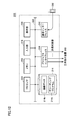
- FIG. 10 is a functional block diagram of the decoder 210 according to the embodiment of the present invention.
- the decoder 210 includes an input buffer 2102, an entropy decoding unit 2104, an inverse orthogonal transform / scaling unit 2112, a data format inverse transform unit 2114, a deblock filter 2116, and an intra frame prediction unit 2118.
- the decoder 210 replaces the decoder 910 shown in FIG. 3 with a data format inverse conversion unit 2114 instead of the addition unit 9114 that adds the residual image and the previously calculated prediction image (interpolation information).
- the main difference is that.
- the operation of the control unit 2130 is also different from that of the control unit 9130.
- the functions of the input buffer 2102, the entropy decoding unit 2104, the inverse orthogonal transform / scaling unit 2112, the deblocking filter 2116, the intra frame prediction unit 2118, the motion compensation unit 2120, the switching unit 2122, the control unit 2130, and the output buffer 2142 3 includes an input buffer 9102, an entropy decoding unit 9104, an inverse orthogonal transform / scaling unit 9112, a deblocking filter 9116, an intra frame prediction unit 9118, a motion compensation unit 9120, a switching unit 9122, a control unit 9130, and an output. It is similar to the buffer 9142.
- decoder 210 the original image is restored from the bit stream from the encoder 120 shown in FIG. Referring to FIG. 10, a bit stream is provided to input buffer 2102.
- the input buffer 2102 temporarily stores a given bit stream.
- the entropy decoding unit 2104 performs entropy decoding on the bit stream from the input buffer 2102 and, as a result, outputs motion data, quantized transform coefficients, control data, and parameters.
- the motion data is given to the motion compensation unit 2120.
- the inverse orthogonal transform / scaling unit 2112 performs inverse orthogonal transform (typically, discrete Fourier inverse transform) and scaling for the quantized transform coefficient decoded by the entropy decoding unit 2104.
- inverse orthogonal transform typically, discrete Fourier inverse transform
- the data format reverse conversion unit 2114 performs the data format reverse conversion on the macroblock after the data format conversion, and the deblock filter 2116 suppresses the occurrence of block noise on the result. Smooth block boundaries.
- the intra frame prediction unit 2118 generates a prediction image based on adjacent macroblocks.
- the motion compensation unit 2120 generates a predicted image using inter-frame prediction (inter-frame prediction). More specifically, the motion compensation unit 2120 generates a prediction image based on the restored original macroblock and the motion data decoded by the entropy decoding unit 2104.
- One of the predicted images generated by each of the intra-frame prediction unit 2118 and the motion compensation unit 2120 is appropriately selected by the switching unit 2122 and given to the data format inverse conversion unit 2114.
- the control unit 2130 controls processing in the inverse orthogonal transform / scaling unit 2112, the data format inverse transform unit 2114, and the switching unit 2122 based on the control data and parameters decoded by the entropy decoding unit 2104.
- the output buffer 2142 temporarily stores the restored original image (video signal) from the deblock filter 2116.
- the region defined by the remainder in the macroblock after the data format conversion is specified using the flag flag1 and / or the flag flag2.
- the flag flag1 and / or the flag flag2 In other words, by invalidating both the flag flag1 and the flag flag2, it is specified that all regions are defined by residuals.
- encoder 120 more specifically, control unit 1230
- decoder 210 more specifically, control unit 2130
- parameters such as type type, threshold values TH1 and TH2, and remainder operation parameter a are included. Used.
- the type type is a first data format (FIG. 5 (a)) that combines a residue and a residual in pixel units, and a second data format (FIG. 5 (in) that combines a residue and a residual in macroblock units. It corresponds to a parameter indicating which of b)) is selected.
- Flag flag1 is assigned to each pixel constituting the macroblock, and each flag flag1 indicates whether the corresponding pixel is defined by a residue or a residual.
- each flag flag1 indicates whether the corresponding pixel is defined by a residue or a residual.
- the threshold value TH1 is used as a determination criterion for determining which of the plurality of pixels constituting each macroblock should be defined as a residue or a residual. That is, the threshold value TH1 is a criterion for specifying an area in which the pixel value is to be defined by the remainder among the pixels constituting the residual image (residual macroblock). It is transmitted to the decoder side as additional information.
- the remainder calculation parameter a is a parameter for determining the coefficient D used in the modulo calculation unit 1278 (FIG. 6).
- the threshold value for the pseudo gradient macroblock generated in the gradient image generation unit 1270 (FIG. 4) may be used as the remainder calculation parameter a. That is, the threshold value for determining each gradation in the Lookup table 1274 as shown in FIG.
- a plurality of Lookup tables as shown in FIG. 7 may be prepared, and an identifier indicating which Lookup table is selected may be used as the remainder calculation parameter a.
- Flag flag2 is assigned to each macroblock, and each flagflag2 indicates whether the corresponding macroblock is defined as a residue or a residual. As an alternative configuration, assign flag flag2 only to one of the remainder and residual, and do not assign flag flag2 to the other, so that each macroblock is defined as either residue or residual it can.
- Threshold value TH2 is used as a determination criterion for determining whether to define each of the macroblocks as a residue or a residual. In this determination, the threshold value TH1 is also used.
- (C) Remainder operation parameter a Similar to the remainder calculation parameter a used for the first data format described above, the threshold value for the pseudo gradient macroblock or an identifier indicating whether the Lookup table to be used is selected is included.
- the encoder 120 may perform optimization (rate-distortion optimization) according to speed distortion.
- optimization rate-distortion optimization
- the threshold value TH1 and / or the threshold value TH2 for determining whether to define the remainder or the residual should be the object of this optimization. This optimization can further improve performance.
- FIG. 11 is a schematic diagram illustrating a hardware configuration of the information processing apparatus 100 that functions as a transmitter.
- FIG. 12 is a schematic diagram illustrating a hardware configuration of the information processing apparatus 200 that functions as a receiver.
- information processing apparatus 100 includes a processor 104, a memory 106, a camera interface 108, a communication interface 112, a hard disk 114, an input unit 116, and a display unit 118. Each of these components is configured to be able to perform data communication with each other via a bus 122.
- the processor 104 implements the encoding process according to the embodiment of the present invention by reading a program stored in the hard disk 114 or the like, developing it in the memory 106 and executing it.
- the memory 106 functions as a working memory for the processor 104 to execute processing.
- the camera interface 108 is connected to a plurality of cameras 10 and acquires images captured by the respective cameras 10.
- the acquired image may be stored in the hard disk 114 or the memory 106.
- the hard disk 114 holds an encoding program 114a for realizing the encoding process described above in a nonvolatile manner.
- the input unit 116 typically includes a mouse, a keyboard, etc., and accepts an operation from the user.
- the display unit 118 notifies the user of processing results and the like.
- the communication interface 112 is connected to the wireless transmission device 102 and the like, and outputs data output as a result of processing by the processor 104 to the wireless transmission device 102.
- information processing apparatus 200 includes a processor 204, a memory 206, a projector interface 208, a communication interface 212, a hard disk 214, an input unit 216, and a display unit 218. Each of these components is configured to be able to perform data communication with each other via a bus 222.
- the processor 204, the memory 206, the input unit 216, and the display unit 218 are the same as the processor 104, the memory 106, the input unit 116, and the display unit 118 shown in FIG. Absent.
- the projector interface 208 is connected to the stereoscopic display device 300 and outputs the multi-viewpoint image restored by the processor 204 to the stereoscopic display device 300.
- the communication interface 212 is connected to the wireless transmission device 202 or the like, receives a bit stream transmitted from the information processing device 100, and outputs it to the processor 204.
- the hard disk 214 holds a decoding program 214a for realizing decoding and image data 214b including the restored original image in a nonvolatile manner.
- the hardware itself of the information processing apparatuses 100 and 200 shown in FIGS. 10 and 11 and the operation principle thereof are general, and are essential for realizing encoding / decoding according to the embodiment of the present invention.
- the part is software (instruction code) such as an encoding program 114a and a decoding program 214a stored in a storage medium such as a hard disk.
- Such encoding program 114a and decoding program 214a are stored and distributed in storage media such as optical storage media, magnetic storage media, and semiconductor storage media.
- a storage medium for storing such a program can also be included in the scope of the present invention.
- the encoding program 114a and / or the decoding program 214a may be configured to execute processing using a module provided by an OS (Operating System).
- OS Operating System
- the encoding program 114a and / or the decoding program 214a does not include some modules, but even such a case is included in the technical scope of the present invention.
- All or part of the functions of the information processing apparatus 100 and / or the information processing apparatus 200 may be realized by using a dedicated integrated circuit such as an ASIC (Application Specific Integrated Circuit) or an FPGA (Field-Programmable Gate Array). Or programmable hardware such as DSP (Digital Signal Processor).
- ASIC Application Specific Integrated Circuit
- FPGA Field-Programmable Gate Array
- DSP Digital Signal Processor
- a threshold is applied to a residual macroblock obtained by subtracting a motion compensation macroblock (intra macroblock or inter macroblock) from an original macroblock, whereby a remainder is obtained. And an area defined by each of the residuals is determined.
- This threshold and other parameters required for data format conversion may be optimized dynamically or statically using a speed optimization loop.
- a modulo operation is performed to calculate the remainder.
- the coefficient D that becomes the denominator (modulus) in this modulo calculation is determined based on the gradient image of the same motion compensation macroblock (or motion compensation frame) as the target macroblock.
- This gradient image ((pseudo) gradient macroblock or (pseudo) gradient frame) is generated from an intra macroblock (or intra frame) or an inter macroblock (or inter frame).
- the gradient may be calculated between macroblocks over a plurality of frames. That is, the gradient image may be calculated over the time domain and / or the spatial domain.
- the coefficient D used in the modulo calculation is determined according to the gradient image calculated in this way.
- the coefficient D used in the modulo operation is applied to a (pseudo) gradient macroblock (or gradient frame) for determining whether each region should be defined as a residue or a residual. It may be set to the same threshold value.
- a data format for a macroblock or a frame (1) a data format in which each area is defined only by a remainder, and (2) each area is defined by a combination of a remainder and a residual.
- a macroblock or frame is all zeros, a combination of residuals and zeros, all residuals, a combination of residuals and zeros, all residuals, a combination of residuals and residuals, a combination of residuals, residuals and zeros , And so on.
- the configuration example applied to MPEG-4 AVC which is one of the compression standards for moving images, has been shown.
- the data compression process after the data format conversion is executed according to a procedure in accordance with the standard.
- the data format conversion process is optimized in accordance with parameters related to data compression. Any data compression tool for still images / moving images / multi-viewpoint images can be applied at the final stage of encoding.
- a decoder corresponding to the data format according to the embodiment of the present invention is used.
- information on the data format type (type) is transmitted from the encoder to the decoder. By adding such information, compatibility with conventional devices and existing standards can be ensured.
- the bitstream includes parameters related to encoding and parameters related to the data format in addition to parameters required by the standard.
- motion data typically motion vectors
- a parameter for data format conversion is used to distinguish between a region defined by a remainder and a region defined by a residual (or as zero).
- a gradient image is generated from an intra macroblock (or intra frame) or an inter macro block (or inter frame). Based on this gradient image, a coefficient (denominator) used for the inverse modulo operation for restoring the region defined by the remainder is determined.
- an area defined by a residual may be further compensated based on a motion compensation macroblock / frame or a synthesized macroblock / frame.
- the corresponding value of the motion compensation macroblock / frame may be assigned to a region where zero is set.
- the area defined by the remainder is restored by the inverse modulo operation as described above.
- a method for converting an image data format used in image data compression processing can be applied to a multi-viewpoint image captured by a plurality of cameras, a multi-viewpoint distance image captured by a plurality of depth cameras, a series of still images or still images, or image data of an arbitrary format.
- Compressing data with an encoding tool improved in the standard an improved data compression tool for still images / moving images / multi-view images.
- the data format conversion is executed in units of blocks (macroblocks) composed of a plurality of pixels.
- the data format conversion process includes the following steps.
- each pixel of a block data format is set to a predetermined value.
- a step of generating a difference block that is, a residual macroblock based on the inter macroblock, the intra macroblock, and the original macroblock, according to the parameter.
- a residual macroblock is configured based on the predetermined parameter.
- a step of converting the zero (these pixels, the residual is treated as a pixel of zero)
- E A step of generating a pseudo gradient image based on an inter macroblock or an intra macroblock
- f A step of setting a parameter for determining a remainder by modulo operation based on the pseudo gradient image
- g A step of converting a pixel whose value is to be converted into a remainder based on a parameter set set for the original macro and modulo operation.
- a process of executing an optimization process for improving the compression efficiency and the compression quality by using the existing optimization process for the data compression parameter and the data format conversion parameter according to the standard of the network (k ) Bitstream of image data compressed using an improved data compression tool for still / moving / multi-view images, information about each compressed macroblock, and corresponding data format inverse transform Providing parameters to the data recovery tool (l) Based on the inter-macroblock or intra-macroblock, and the residual and zero pixels, for the image with no flag enabled, the original pixel value from the residual Step to restore (m) Inter macro block or Intra
- a step of executing an inverse modulo operation based on a macroblock and a residual pixel indicated by a flag in the execution of the inverse modulo operation, corresponding parameters for the modulo operation extracted from the received bitstream are used.
- Embodiments of the present invention provide a configuration in which both data format conversion and data compression are incorporated into a single system. By adopting such a configuration, the complexity of the system can be avoided. Furthermore, since compatibility with existing compression standards can be maintained, it is possible to easily incorporate new data format conversion (encoding) according to the embodiment of the present invention. As described above, in the encoding / decoding system according to the embodiment of the present invention, if the remainder information is not used, the same processing as that in the existing standard can be realized. Therefore, compatibility can be maintained.
- the encoding / decoding system includes, for example, distributed source coding, distributed video coding, and data compression for still images / moving images / multi-view images. It can be applied to various image systems.
- data compression is performed by using a new data format within the frame of the existing standard related to data compression for still images / moving images / multi-viewpoint images. Efficiency can be further increased.
- the change to the data compression tool for still images / moving images / multi-view images in accordance with the existing standards is minimal.
- the data compression tool for still images / moving images / multi-viewpoint images, in which the encoding / decoding system according to the embodiment of the present invention is implemented invalidates the processing according to the embodiment of the present invention. Compatibility with existing standards can still be maintained.
- 1 stereoscopic video playback system 2 subject, 10 camera, 100, 200 information processing device, 102, 202 wireless transmission device, 104, 204 processor, 106, 206 memory, 108 camera interface, 110 preprocessor, 112, 212 communication interface, 114, 214 hard disk, 114a encoding program, 116, 216 input unit, 118, 218 display unit, 120, 820 encoder, 122, 222 bus, 208 projector interface, 210, 910 decoder, 214a decoding program, 214b image data, 220 Post processor, 300 stereoscopic display device, 302 projector array, 310 display screen, 312 Diffusion film, 314, condensing lens, 1202, 2102, 8202, 9102 input buffer, 1204, 8204 division unit, 1206 data format conversion unit, 1208, 8208 orthogonal transformation / quantization unit, 1210, 8210 local decoder, 1212, 2112 8212,9112, inverse orthogonal transform / scaling unit, 1214,2114 data
Abstract
Description
まず、本発明の実施の形態に係るエンコーディング/デコーディングシステムについての理解を容易化するために、典型的な応用例について説明する。本発明の実施の形態に係るエンコーディング/デコーディングシステムの応用範囲は、以下に示す構成に限定されるものではなく、任意の構成に応用できる。また、エンコーディングおよびデコーディングのいずれか一方のみを実行する方法、装置、プログラム、そのプログラムを格納する記憶媒体などについても、本願発明の範囲に含まれ得る。
まず、本発明の実施の形態に係るエンコーディング/デコーディングシステムに関連する技術について説明する。動画像の圧縮規格の一つである、MPEG-4 AVC(ITU-T Recommendation H.264|ISO/IEC 14496-10 Advanced Video Coding)のエンコーディングおよびデコーディングについて説明する。
本発明の実施の形態に係るエンコーディング/デコーディングシステムは、上述したような既存の規格に組み込むことができるデータフォーマット変換処理を含む。本発明の実施の形態に係るエンコーディング/デコーディングシステムでは、剰余画像(remainder image)という概念を導入してデータ圧縮効率をより高める。すなわち、本発明の実施の形態においては、既存の規格で用いられる残差だけではなく、剰余を用いることで、データ圧縮の効率を高めるとともに、その品質も向上させることができる。
まず、本発明の実施の形態に係るエンコーディング/デコーディングシステムを構成するエンコーダー120の機能構成について説明する。図4は、本発明の実施の形態に係るエンコーダー120の機能ブロック図である。図4を参照して、エンコーダー120は、入力バッファ1202と、分割部1204と、データフォーマット変換部1206と、直交変換・量子化部1208と、ローカルデコーダー1210と、制御部1230と、動き推定部1240と、出力バッファ1242と、エントロピー符号化部1250とを含む。また、ローカルデコーダー1210は、逆直交変換・スケーリング部1212と、データフォーマット逆変換部1214と、デブロックフィルター1216と、イントラフレーム予測部1218と、動き補償部1220と、切換部1222とを含む。
次に、エンコーダー120における処理手順について説明する。図4を参照して、入力ソースからの映像信号が入力バッファ1202へ与えられる。この映像信号としては、複数のカメラ10(カメラアレイ)によって撮像された多視点画像、複数のDepthカメラから出力される多視点距離画像、一連の静止画像あるいは静止画像、および、任意の形式の画像データを含む。入力バッファ1202には、これらの映像信号が一時的に格納され、これらの全部または一部が入力データとして分割部1204へ与えられる。以下では、説明の簡略化のため、時間領域および空間領域のいずれか一方の領域に配置されたフレーム列(すなわち、単一のカメラで撮像された動画像や多視点の静止画像など)を処理対象とする。もちろん、時間領域および空間領域の両方に配置されたフレーム列に対しても同様に適用できる。但し、この場合には、各フレーム(または、マクロブロック)について、時間領域および空間領域のそれぞれにおける関連性を考慮して、補間情報を算出することになる。
[F.データフォーマット変換部1206における処理]
次に、本発明の実施の形態に係るデータフォーマット変換部1206(図4)における処理について詳述する。
上述したように、本発明の実施の形態においては、剰余のみで定義する構成、および剰余と残差とを組み合せて定義する構成の両方を採用し得る。後者の場合には、さらに、(1)画素単位での剰余と残差との組み合わせ、および、(2)マクロブロック単位での剰余と残差(あるいは、すべてゼロ)との組み合わせの両方を採用し得る。
上述したように、データフォーマット変換部1206から出力されるデータフォーマット変換後のマクロブロックには複数のタイプがあるので、サイド情報の一部として、このデータフォーマット変換の手順を示す情報(データフォーマットタイプ(type))が用いられる。但し、残差で定義される領域については、サイド情報を含めないようにしてもよい。つまり、対応するサイド情報が存在する領域(画素またはマクロブロック)について剰余で定義されていることが暗示される。
図6は、本発明の実施の形態に係るデータフォーマット変換部1206の機能ブロック図である。図6を参照して、データフォーマット変換部1206は、減算部1260と、比較部1262と、マスク生成部1264と、処理選択部1266と、勾配画像生成部1270と、係数選択部1272と、Lookupテーブル1274と、モジュロ演算部1278と、合成部1280とを含む。
(iii-2)(1回以上の)ガウシアンスムージング処理(あるいは、メディアンフィルタ処理)
(iii-3)一連のモルフォロジカル処理(例えば、(1回以上の)膨脹処理、(1回以上の)収縮処理、(1回以上の)膨脹処理)
(iii-4)(1回以上の)ガウシアンスムージング処理
以上のような処理によって、動き補償マクロブロックを構成するカラーコンポーネント別に疑似勾配マクロブロックが生成される。
図8は、本発明の実施の形態に係るデータフォーマット変換部1206の別の機能ブロック図である。図8を参照して、データフォーマット変換部1206は、図6に示すデータフォーマット変換部1206に比較して、マスク生成部1264、処理選択部1266、および合成部1280に代えて、積算部1265、評価部1267、および切換部1269を設けたものである。その他のコンポーネントの詳細については、上述したのでその内容は繰り返さない。
次に、本発明の実施の形態に係る直交変換・量子化部1208(図4)における処理について詳述する。直交変換・量子化部1208は、データフォーマット変換部1206からのデータフォーマット変換後のマクロブロックに対して、直交変換、量子化、およびスケーリングを実行する。
次に、本発明の実施の形態に係るデータフォーマット逆変換部1214(図4)における処理について詳述する。
上述したように、データフォーマット変換部1206から出力されるデータフォーマット変換後のマクロブロックには複数のタイプがあるので、サイド情報に含まれるデータフォーマットタイプに基づいて、データフォーマット逆変換の手順が選択される。
図9は、本発明の実施の形態に係るデータフォーマット逆変換部1214の機能ブロック図である。図9を参照して、データフォーマット逆変換部1214は、処理選択部1290と、加算部1292と、勾配画像生成部1270と、係数選択部1272と、Lookupテーブル1274と、逆モジュロ演算部1298と、合成部1294とを含む。なお、図6に示すデータフォーマット変換部1206を構成するコンポーネントと同様の処理を実行するコンポーネントについては、同じ参照符号を付している。
候補値C(1)=1×8+3=11 (SIとの差=3)
候補値C(2)=2×8+3=19 (SIとの差=11)
…
これらの候補値C(q’)のうち、動き補償マクロブロックの対応する画素値SIとの差が最も小さくなる候補値C(1)が選択され、オリジナルマクロブロックの対応する画素値は「11」に決定される。このようにして、オリジナルマクロブロックの各画素の画素値がカラーコンポーネント別にそれぞれ決定される。この算出された画素値が合成部1294へ出力される。合成部1294は、画素毎に入力される剰余または残差を結合して、オリジナルマクロブロック(Original MB)を出力する。
次に、本発明の実施の形態に係るエンコーディング/デコーディングシステムを構成するデコーダー210(図1)の機能構成について説明する。
次に、デコーダー210における処理手順について説明する。デコーダー210では、図4に示すエンコーダー120からのビットストリームからオリジナル画像を復元する。図10を参照して、ビットストリームが入力バッファ2102へ与えられる。入力バッファ2102は、与えられたビットストリームを一時的に格納する。エントロピー復号部2104は、入力バッファ2102からのビットストリームに対してエントロピー復号を行ない、その結果として、動きデータ、量子化後の変換係数、ならびに、制御データおよびパラメータを出力する。動きデータは、動き補償部2120へ与えられる。
次に、本発明の実施の形態に係るエンコーディング/デコーディングシステムにおいて用いられるパラメータおよびサイド情報について詳述する。
(A)フラグflag1
マクロブロックを構成する画素毎にフラグflag1が割り当てられ、フラグflag1の各々は、対応する画素が剰余および残差のいずれで定義されるのかを示す。代替の構成として、剰余および残差の一方にのみフラグflag1を割当て、他方にはフラグflag1を割り当てないようにすることで、各画素について、剰余および残差のいずれで定義されるのかを特定できる。
しきい値TH1は、各マクロブロックを構成する複数の画素の各々について、剰余および残差のいずれで定義すべきかを判断するための判断基準として用いられる。つまり、しきい値TH1は、残差画像(残差マクロブロック)を構成する画素のうちその画素値を剰余で定義すべき領域を特定するための判断基準であり、このしきい値TH1は、付加情報としてデコーダー側へ送信される。
剰余演算用パラメータaは、モジュロ演算部1278(図6)において用いられる係数Dを決定するためのパラメータである。一例として、勾配画像生成部1270(図4)において生成される疑似勾配マクロブロックに対するしきい値を、剰余演算用パラメータaとしてもよい。つまり、図7に示すようなLookupテーブル1274における各階調を決定するしきい値が剰余演算用パラメータaになる。
(A)フラグflag2
マクロブロック毎にフラグflag2が割り当てられ、フラグflag2の各々は、対応するマクロブロックが剰余および残差のいずれで定義されるのかを示す。代替の構成として、剰余および残差の一方にのみフラグflag2を割当て、他方にはフラグflag2を割り当てないようにすることで、各マクロブロックについて、剰余および残差のいずれで定義されるのかを特定できる。
しきい値TH2は、マクロブロックの各々について、剰余および残差のいずれで定義すべきかを判断するための判断基準として用いられる。この判断においては、しきい値TH1も用いられる。
上述の第1データフォーマットに対して用いられる剰余演算用パラメータaと同様に、疑似勾配マクロブロックに対するしきい値、あるいは、使用するLookupテーブルを選択するのかを示す識別子を含む。
次に、上述の送信機および受信機を実現するためのハードウェア構成の一例について説明する。図11は、送信機として機能する情報処理装置100のハードウェア構成を示す模式図である。図12は、受信機として機能する情報処理装置200のハードウェア構成を示す模式図である。
本発明の実施の形態においては、オリジナルマクロブロックから動き補償マクロブロック(イントラマクロブロック、または、インターマクロブロック)を減じた残差マクロブロックに対して、しきい値が適用されることで、剰余および残差のそれぞれで定義される領域が決定される。このしきい値およびデータフォーマット変換に必要な他のパラメータは、速度最適化ループを用いて動的または静的に最適化されてもよい。
(b)インターマクロブロック、または、イントラマクロブロック、ならびにオリジナルマクロブロックに基づいて、差分ブロック、すなわち残差マクロブロックを生成する工程
(c)所定のパラメータおよび残差マクロブロックに基づいて、その値を剰余に変換すべきと判断された画素にフラグを有効化する工程
(d)所定のパラメータに基づいて、残差マクロブロックを構成する画素のうち、その値をゼロにすべきと判断された画素について、ゼロに変換する工程(これらの画素は、残差がゼロの画素として取り扱われる)
(e)インターマクロブロック、または、イントラマクロブロックに基づいて、疑似勾配画像を生成する工程
(f)当該疑似勾配画像に基づいて、モジュロ演算によって剰余を決定するためのパラメータを設定する工程
(g)オリジナルマクロおよびモジュロ演算について設定されたパラメータセットに基づいて、その値を剰余に変換すべきと判断された画素について、剰余に変換する工程
(h)静止画像/動画像/多視点画像に対するデータ圧縮に係る既存の規格に類似したデータ圧縮に係る処理を、新たなデータフォーマット変換後のマクロブロックに対して実行する工程
(i)データフォーマット変換のためのパラメータを規格に従う最適化処理に追加して、当該パラメータのデータ圧縮を実行する工程
(j)新たなデータフォーマットの規格に従うデータ圧縮パラメータおよびデータフォーマット変換のためのパラメータに対して、既存の最適化処理を用いて、その圧縮効率および圧縮品質をより高くするための最適化処理を実行する工程
(k)静止画像/動画像/多視点画像に対する改良されたデータ圧縮ツールを用いて圧縮された画像データのビットストリーム、各圧縮されたマクロブロックについての情報、ならびに、データフォーマット逆変換のための対応するパラメータをデータ復元ツールに提供する工程
(l)インターマクロブロック、または、イントラマクロブロック、ならびに残差およびゼロ画素に基づいて、フラグが有効化されていない画像について、残差からオリジナルの画素値を復元する工程
(m)インターマクロブロック、または、イントラマクロブロック、ならびにフラグによって示される剰余の画素に基づいて、逆モジュロ演算を実行する工程(逆モジュロ演算の実行にあたって、受信したビットストリームから抽出されたモジュロ演算のための対応するパラメータが利用される)
上述の説明においては、データフォーマット変換およびデータフォーマット逆変換をマクロブロック単位で実行する場合について説明したが、画像全体に適用できることはいうまでもない。具体的には、オリジナル画像全体についての残差画像を先に生成し、当該生成した残差画像に対して、上述した処理を画像単位で実行してもよい。
本発明の実施の形態は、データフォーマット変換およびデータ圧縮の両方が単一のシステムに組み込まれた構成を提供する。このような構成を採用することで、システムの複雑化を回避できる。さらに、既存の圧縮規格との互換性を維持できるので、本発明の実施の形態に係る新たなデータフォーマット変換(エンコーディング)の組み込みが容易化できる。上述したように、本発明の実施の形態に係るエンコーディング/デコーディングシステムにおいては、剰余の情報を用いなければ、既存の規格での処理と同一の処理を実現することもできる。そのため、互換性を維持できる。
Claims (7)
- 互いに関連した情報を含む複数の入力画像をエンコーディングする方法であって、
先行の1つ以上の入力画像から後続の入力画像に含まれる変化成分を示す動き画像を推定するステップと、
前記後続の入力画像と推定された前記動き画像との差分から残差画像を生成するステップと、
前記残差画像の画素値に基づいて、前記残差画像を構成する画素のうちその画素値を剰余で定義すべき領域を特定するステップと、
特定された前記剰余で定義すべき領域についての画素値を剰余に変換するステップと、
変換後の残差画像と、前記剰余で定義すべき領域を特定する付加情報とをエンコーディングするステップとを含む、方法。 - 前記変換後の残差画像を構成する画素のうち前記剰余で定義された画素に対して逆モジュロ演算を実行することで、前記残差画像をデコーディングするステップをさらに含み、
前記推定するステップは、デコーディングされた残差画像に基づいて、前記動き画像を推定するステップを含む、請求項1に記載の方法。 - 前記特定するステップは、前記残差画像を構成する各画素の画素値の大きさに基づいて、前記剰余で定義すべき領域を画素単位で決定するステップを含み、
前記付加情報は、前記残差画像を構成する画素のうち、剰余で定義された画素をそれぞれ特定するための情報を含む、請求項1または2に記載の方法。 - 前記特定するステップは、前記残差画像を所定サイズの分割した各ブロックについて、当該ブロックを構成するそれぞれの画素の画素値についての評価を結合した結果に基づいて、前記剰余で定義すべき領域をブロック単位で決定するステップを含み、
前記付加情報は、前記残差画像に含まれるブロックのうち、剰余で定義されたブロックを特定するための情報を含む、請求項1~3のいずれか1項に記載の方法。 - 前記変換するステップは、
前記剰余で定義すべき領域についての画素値に対してモジュロ演算を実行するステップと、
前記動き画像の勾配情報を取得するステップと、
勾配強度とモジュロ演算の法となる値との予め定められた対応関係を参照して、取得した前記勾配情報に基づいてモジュロ演算の法となる値を決定するステップとを含む、請求項1~4のいずれか1項に記載の方法。 - 互いに関連した情報を含む複数の入力画像をエンコーディングするプログラムを格納する記憶媒体であって、当該プログラムは、コンピュータに、
先行の1つ以上の入力画像から後続の入力画像に含まれる変化成分を示す動き画像を推定するステップと、
前記後続の入力画像と推定された前記動き画像との差分から残差画像を生成するステップと、
前記残差画像の画素値に基づいて、前記残差画像を構成する画素のうちその画素値を剰余で定義すべき領域を特定するステップと、
特定された前記剰余で定義すべき領域についての画素値を剰余に変換するステップと、
変換後の残差画像と、前記剰余で定義すべき領域を特定する付加情報とをエンコーディングするステップとを実行させる、記憶媒体。 - 互いに関連した情報を含む複数の入力画像をエンコーディングする装置であって、
先行の1つ以上の入力画像から後続の入力画像に含まれる変化成分を示す動き画像を推定する手段と、
前記後続の入力画像と推定された前記動き画像との差分から残差画像を生成する手段と、
前記残差画像の画素値に基づいて、前記残差画像を構成する画素のうちその画素値を剰余で定義すべき領域を特定する手段と、
特定された前記剰余で定義すべき領域についての画素値を剰余に変換する手段と、
変換後の残差画像と、前記剰余で定義すべき領域を特定する付加情報とをエンコーディングする手段とを備える、装置。
Priority Applications (4)
| Application Number | Priority Date | Filing Date | Title |
|---|---|---|---|
| CN201480018699.2A CN105075256A (zh) | 2013-03-27 | 2014-03-12 | 编码多个输入图像的方法及装置、存放程序的存储介质 |
| EP14773126.9A EP2981082A1 (en) | 2013-03-27 | 2014-03-12 | Method for encoding a plurality of input images and storage medium and device for storing program |
| KR1020157030237A KR20150137081A (ko) | 2013-03-27 | 2014-03-12 | 복수의 입력 화상을 인코딩하는 방법, 프로그램을 격납하는 기억 매체 및 장치 |
| US14/780,914 US20160057414A1 (en) | 2013-03-27 | 2014-03-12 | Method for encoding a plurality of input images, and storage medium having program stored thereon and apparatus |
Applications Claiming Priority (2)
| Application Number | Priority Date | Filing Date | Title |
|---|---|---|---|
| JP2013066313A JP2014192701A (ja) | 2013-03-27 | 2013-03-27 | 複数の入力画像をエンコーディングする方法、プログラムおよび装置 |
| JP2013-066313 | 2013-03-27 |
Publications (1)
| Publication Number | Publication Date |
|---|---|
| WO2014156647A1 true WO2014156647A1 (ja) | 2014-10-02 |
Family
ID=51623630
Family Applications (1)
| Application Number | Title | Priority Date | Filing Date |
|---|---|---|---|
| PCT/JP2014/056483 WO2014156647A1 (ja) | 2013-03-27 | 2014-03-12 | 複数の入力画像をエンコーディングする方法、プログラムを格納する記憶媒体および装置 |
Country Status (6)
| Country | Link |
|---|---|
| US (1) | US20160057414A1 (ja) |
| EP (1) | EP2981082A1 (ja) |
| JP (1) | JP2014192701A (ja) |
| KR (1) | KR20150137081A (ja) |
| CN (1) | CN105075256A (ja) |
| WO (1) | WO2014156647A1 (ja) |
Families Citing this family (2)
| Publication number | Priority date | Publication date | Assignee | Title |
|---|---|---|---|---|
| JP2014082541A (ja) * | 2012-10-12 | 2014-05-08 | National Institute Of Information & Communication Technology | 互いに類似した情報を含む複数画像のデータサイズを低減する方法、プログラムおよび装置 |
| JP6711913B2 (ja) * | 2016-06-14 | 2020-06-17 | パナソニック インテレクチュアル プロパティ コーポレーション オブ アメリカPanasonic Intellectual Property Corporation of America | 三次元データ符号化方法、三次元データ復号方法、三次元データ符号化装置及び三次元データ復号装置 |
Citations (2)
| Publication number | Priority date | Publication date | Assignee | Title |
|---|---|---|---|---|
| JPH04343576A (ja) * | 1991-05-21 | 1992-11-30 | Matsushita Electric Ind Co Ltd | 高能率符号化方法と高能率符号の復号方法 |
| JP2011514024A (ja) * | 2008-01-21 | 2011-04-28 | テレフオンアクチーボラゲット エル エム エリクソン(パブル) | 予測に基づく画像処理 |
Family Cites Families (6)
| Publication number | Priority date | Publication date | Assignee | Title |
|---|---|---|---|---|
| US5768438A (en) * | 1994-10-19 | 1998-06-16 | Matsushita Electric Industrial Co., Ltd. | Image encoding/decoding device |
| CN1258925C (zh) * | 2003-06-27 | 2006-06-07 | 中国科学院计算技术研究所 | 多视角视频编解码预测补偿方法及装置 |
| JP4662171B2 (ja) * | 2005-10-20 | 2011-03-30 | ソニー株式会社 | 符号化装置および方法、復号化装置および方法、プログラム、並びに記録媒体 |
| US7706619B2 (en) * | 2005-11-30 | 2010-04-27 | Brother Kogyo Kabushiki Kaisha | Image processing device that produces high-quality reduced image at fast processing speed |
| CN104124982B (zh) * | 2008-12-09 | 2017-04-12 | 日本电信电话株式会社 | 编码方法以及编码装置 |
| AU2011201336B2 (en) * | 2011-03-23 | 2013-09-05 | Canon Kabushiki Kaisha | Modulo embedding of video parameters |
-
2013
- 2013-03-27 JP JP2013066313A patent/JP2014192701A/ja not_active Withdrawn
-
2014
- 2014-03-12 US US14/780,914 patent/US20160057414A1/en not_active Abandoned
- 2014-03-12 EP EP14773126.9A patent/EP2981082A1/en not_active Withdrawn
- 2014-03-12 CN CN201480018699.2A patent/CN105075256A/zh active Pending
- 2014-03-12 WO PCT/JP2014/056483 patent/WO2014156647A1/ja active Application Filing
- 2014-03-12 KR KR1020157030237A patent/KR20150137081A/ko not_active Application Discontinuation
Patent Citations (2)
| Publication number | Priority date | Publication date | Assignee | Title |
|---|---|---|---|---|
| JPH04343576A (ja) * | 1991-05-21 | 1992-11-30 | Matsushita Electric Ind Co Ltd | 高能率符号化方法と高能率符号の復号方法 |
| JP2011514024A (ja) * | 2008-01-21 | 2011-04-28 | テレフオンアクチーボラゲット エル エム エリクソン(パブル) | 予測に基づく画像処理 |
Non-Patent Citations (5)
| Title |
|---|
| MEHRDAD PANAHPOUR TEHRANI ET AL.: "A hybrid representation for multi-view images, 3DTV-Conference: The True Vision - Capture", TRANSMISSION AND DISPLAY OF 3D VIDEO (3DTV-CON, 15 October 2012 (2012-10-15), pages 1 - 4, XP032275888 * |
| MEHRDAD PANAHPOUR TEHRANI ET AL.: "A New Data Format for Multiview Video", IPSJ SIG TECHNICAL REPORT 2013-AVM-80, vol. 2013-AVM, no. 6, 22 February 2013 (2013-02-22), pages 1 - 5, XP055280613 * |
| MEHRDAD PANAHPOUR TEHRANI ET AL.: "The Adaptive Distributed Source Coding of Multi-View Images in Camera Sensor Networks", IEICE TRANSACTIONS ON FUNDAMENTALS OF ELECTRONICS, COMMUNICATIONS AND COMPUTER SCIENCES, vol. E88-A, no. 10, 1 October 2005 (2005-10-01), pages 2835 - 2843, XP001234495 * |
| P. MERKLE; K. MULLER; A. SMOLIC; T. WIEGAND: "Efficient Compression of Multi-view Video Exploiting inter-view dependencies based on H.264/MPEG4-AVC", PROC. ICME, 2006, pages 1717 - 1720, XP032965093, DOI: doi:10.1109/ICME.2006.262881 |
| THOMAS WIEGAND; GARY J. SULLIVAN; GISLE BJONTEGAARD; AJAY LUTHRA: "Overview of the H.264/AVC Video Coding Standard", IEEE TRANSACTIONS ON CIRCUITS AND SYSTEMS FOR VIDEO TECHNOLOGY, vol. 13, no. 7, July 2003 (2003-07-01), pages 560 - 576, XP008129745, DOI: doi:10.1109/TCSVT.2003.815165 |
Also Published As
| Publication number | Publication date |
|---|---|
| EP2981082A1 (en) | 2016-02-03 |
| JP2014192701A (ja) | 2014-10-06 |
| US20160057414A1 (en) | 2016-02-25 |
| CN105075256A (zh) | 2015-11-18 |
| KR20150137081A (ko) | 2015-12-08 |
Similar Documents
| Publication | Publication Date | Title |
|---|---|---|
| JP6633694B2 (ja) | 多視点信号コーデック | |
| JP6178017B2 (ja) | ステレオビデオのための深度認識向上 | |
| JP5575908B2 (ja) | 2dビデオデータの3dビデオデータへの変換のための深度マップ生成技法 | |
| CA2692250C (en) | Video encoding and decoding methods using residual prediction, and corresponding apparatuses | |
| WO2014050830A1 (ja) | 画像符号化方法、画像復号方法、画像符号化装置、画像復号装置、画像符号化プログラム、画像復号プログラム及び記録媒体 | |
| KR20120000485A (ko) | 예측 모드를 이용한 깊이 영상 부호화 장치 및 방법 | |
| JP5902814B2 (ja) | 映像符号化方法および装置、映像復号方法および装置、及びそれらのプログラム | |
| JPWO2008081810A1 (ja) | 映像符号化方法及び復号方法、それらの装置、それらのプログラム並びにプログラムを記録した記憶媒体 | |
| WO2014156648A1 (ja) | 複数の入力画像をエンコーディングする方法、プログラムを格納する記憶媒体および装置 | |
| US20150365698A1 (en) | Method and Apparatus for Prediction Value Derivation in Intra Coding | |
| JP6039178B2 (ja) | 画像符号化装置、画像復号装置、並びにそれらの方法及びプログラム | |
| CN115486068A (zh) | 用于视频编码中基于深度神经网络的帧间预测的方法和设备 | |
| WO2014104104A1 (ja) | 映像符号化装置および方法、映像復号装置および方法、及びそれらのプログラム | |
| JP6457248B2 (ja) | 画像復号装置、画像符号化装置および画像復号方法 | |
| KR20140124919A (ko) | 객체 기반 적응적 밝기 보상 방법 및 장치 | |
| WO2015056712A1 (ja) | 動画像符号化方法、動画像復号方法、動画像符号化装置、動画像復号装置、動画像符号化プログラム、及び動画像復号プログラム | |
| WO2011070730A1 (ja) | 映像符号化装置および映像復号装置 | |
| JP4874578B2 (ja) | 画像符号化装置 | |
| WO2014156647A1 (ja) | 複数の入力画像をエンコーディングする方法、プログラムを格納する記憶媒体および装置 | |
| JP6922215B2 (ja) | 動画像符号化装置 | |
| RU2809192C2 (ru) | Кодер, декодер и соответствующие способы межкадрового предсказания | |
| JP6232117B2 (ja) | 画像符号化方法、画像復号方法、及び記録媒体 | |
| JP2015186052A (ja) | 立体映像符号化装置及び立体映像符号化方法 | |
| JP2013128319A5 (ja) | ||
| KR20140124045A (ko) | 객체 기반 적응적 밝기 보상 방법 및 장치 |
Legal Events
| Date | Code | Title | Description |
|---|---|---|---|
| WWE | Wipo information: entry into national phase |
Ref document number: 201480018699.2 Country of ref document: CN |
|
| 121 | Ep: the epo has been informed by wipo that ep was designated in this application |
Ref document number: 14773126 Country of ref document: EP Kind code of ref document: A1 |
|
| REEP | Request for entry into the european phase |
Ref document number: 2014773126 Country of ref document: EP |
|
| WWE | Wipo information: entry into national phase |
Ref document number: 2014773126 Country of ref document: EP |
|
| NENP | Non-entry into the national phase |
Ref country code: DE |
|
| WWE | Wipo information: entry into national phase |
Ref document number: 14780914 Country of ref document: US |
|
| ENP | Entry into the national phase |
Ref document number: 20157030237 Country of ref document: KR Kind code of ref document: A |