WO2014156293A1 - 分析方法 - Google Patents
分析方法 Download PDFInfo
- Publication number
- WO2014156293A1 WO2014156293A1 PCT/JP2014/052245 JP2014052245W WO2014156293A1 WO 2014156293 A1 WO2014156293 A1 WO 2014156293A1 JP 2014052245 W JP2014052245 W JP 2014052245W WO 2014156293 A1 WO2014156293 A1 WO 2014156293A1
- Authority
- WO
- WIPO (PCT)
- Prior art keywords
- analysis method
- protein
- target object
- comparing
- isoelectric point
- Prior art date
- Legal status (The legal status is an assumption and is not a legal conclusion. Google has not performed a legal analysis and makes no representation as to the accuracy of the status listed.)
- Ceased
Links
Images






Classifications
-
- G—PHYSICS
- G01—MEASURING; TESTING
- G01N—INVESTIGATING OR ANALYSING MATERIALS BY DETERMINING THEIR CHEMICAL OR PHYSICAL PROPERTIES
- G01N27/00—Investigating or analysing materials by the use of electric, electrochemical, or magnetic means
- G01N27/26—Investigating or analysing materials by the use of electric, electrochemical, or magnetic means by investigating electrochemical variables; by using electrolysis or electrophoresis
- G01N27/416—Systems
- G01N27/447—Systems using electrophoresis
- G01N27/44756—Apparatus specially adapted therefor
- G01N27/44795—Isoelectric focusing
-
- G—PHYSICS
- G01—MEASURING; TESTING
- G01N—INVESTIGATING OR ANALYSING MATERIALS BY DETERMINING THEIR CHEMICAL OR PHYSICAL PROPERTIES
- G01N27/00—Investigating or analysing materials by the use of electric, electrochemical, or magnetic means
- G01N27/26—Investigating or analysing materials by the use of electric, electrochemical, or magnetic means by investigating electrochemical variables; by using electrolysis or electrophoresis
- G01N27/416—Systems
- G01N27/447—Systems using electrophoresis
- G01N27/44756—Apparatus specially adapted therefor
- G01N27/44773—Multi-stage electrophoresis, e.g. two-dimensional electrophoresis
-
- G—PHYSICS
- G01—MEASURING; TESTING
- G01N—INVESTIGATING OR ANALYSING MATERIALS BY DETERMINING THEIR CHEMICAL OR PHYSICAL PROPERTIES
- G01N27/00—Investigating or analysing materials by the use of electric, electrochemical, or magnetic means
- G01N27/26—Investigating or analysing materials by the use of electric, electrochemical, or magnetic means by investigating electrochemical variables; by using electrolysis or electrophoresis
- G01N27/416—Systems
- G01N27/447—Systems using electrophoresis
- G01N27/44756—Apparatus specially adapted therefor
- G01N27/44773—Multi-stage electrophoresis, e.g. two-dimensional electrophoresis
- G01N27/44778—Multi-stage electrophoresis, e.g. two-dimensional electrophoresis on a common gel carrier, i.e. 2D gel electrophoresis
Definitions
- the present invention relates to an analysis method.
- This application claims priority based on Japanese Patent Application No. 2013-071753 filed in Japan on March 29, 2013, the contents of which are incorporated herein by reference.
- proteome analysis has been actively performed as a method for comprehensive analysis of proteins that directly support biological activities.
- the proteome is a specific cell, organ, and the entire protein produced in the organ.
- One of these techniques two-dimensional electrophoresis, has high resolution and can detect thousands of proteins at a time, and is therefore widely used as a method for separating biological samples such as proteins.
- two-dimensional electrophoresis based on the physical properties of the protein, it is separated by isoelectric focusing and further separated in the molecular weight direction by SDS-PAGE.
- Isoelectric focusing is a technique in which a voltage is applied to a gel and separation is performed based on the difference in isoelectric points of proteins.
- SDS-polyacrylamide gel electrophoresis in which electrophoresis is performed in a state where a protein is complexed with an anionic surfactant sodium dodecyl sulfate (SDS). Widely used.
- Proteins are detected as spots in a polyacrylamide gel on a flat plate by two-dimensional electrophoresis.
- a technique for identifying the protein of each protein spot there is a peptide mass fingerprint method. By using this method, it is possible to determine the type of each protein in the spot. In this method, the spot in the separated gel is transferred to the membrane, and the protein can be similarly identified in the spot in the membrane.
- each protein spot is cut out in a gel state, and the plug-like gel is transferred to a chamber where the liquid buffer does not leak.
- the protein in the gel is digested into peptides with a protein digestion enzyme such as trypsin.
- mass analysis is performed on the peptide eluted from the gel using a mass spectrometer, and the mass spectrum of the peptide fragment predicted from the protein estimated in advance on the database and the pattern of the actually measured mass spectrum are obtained. Compare and identify pre-digested proteins.
- Patent Document 1 As a method for cutting out a spot or band, there is known a method of cutting out using a cutting tool such as a razor or a knife, a pipette tip, or a device that automatically cuts with a cylindrical instrument (see Patent Document 1). In addition, a method of cutting out one block of a gel containing a protein separated by two-dimensional electrophoresis and digesting the protein in the gel into a peptide is also known (see Non-Patent Document 1).
- Non-Patent Document 2 discloses a method of fractionating a protein separated by isoelectric focusing in a solution and a method of fractionating by eluting a protein separated by SDS-PAGE into a solution. These fractionated proteins are fractionated only by one physical property of the protein. Therefore, fractionation is based only on the actual molecular weight or isoelectric point.
- the present invention has been made in consideration of such circumstances, and a target object separated by two-dimensional electrophoresis is increased using a mass analyzer while having a specific isoelectric point region and a molecular weight region.
- One of the purposes is to detect with sensitivity.
- One embodiment of the present invention includes a step of subjecting a target object to two-dimensional electrophoresis in an isoelectric point direction and a molecular weight direction substantially orthogonal to the isoelectric point direction, and a medium including the target object subjected to the two-dimensional electrophoresis
- a target object separated by two-dimensional electrophoresis can be detected with high sensitivity using a mass analyzer while having a specific isoelectric point region and a molecular weight region.
- FIG. 1 is a diagram illustrating an example of a configuration of an isoelectric focusing device 10.
- FIG. 4 is a perspective view of a part of the second-dimensional electrophoresis apparatus 30 and a cross-sectional view taken along the line AA. It is a figure which shows a mode that the IPG gel strip 1 was introduce
- FIG. It is an example of the captured image which imaged the sample separation medium (gel) 37 after two-dimensional electrophoresis was performed.
- FIG. 1 is an example of a flowchart showing a flow of an analysis method according to the first embodiment.
- the analyst prepares an IPG (immobilized pH gradient gel) gel strip 1 (step S100).
- FIG. 2 is a diagram showing an example of the external shape of the IPG gel strip 1.
- the IPG gel strip 1 includes a sample-containing medium 2 for one-dimensional electrophoresis and a support 3 that supports the sample-containing medium 2.
- the sample-containing medium 2 is a medium from which a sample (target object) is separated by isoelectric focusing.
- the sample is a biological sample such as a protein.
- one used as a first-dimensional gel for two-dimensional electrophoresis can be used, for example, gelled by a gelling agent selected from the group consisting of polyacrylamide, agarose, agar, and starch.
- a gelling agent selected from the group consisting of polyacrylamide, agarose, agar, and starch.
- An immobilized pH gradient (IPG) gel or the like is preferably used.
- a plastic plate or film can be used as the support 3.
- the sample contained in the sample-containing medium 2 is provided with the first color pigment.
- the sample-containing medium 2 includes, for example, an isoelectric point marker in which a plurality of substances having known isoelectric points and having a low molecular weight are provided with a second color dye, and the isoelectric point is small.
- a plurality of substances (peptides) having a known molecular weight are mixed with a molecular weight marker provided with a dye of the third color.
- the peptides [7.3], [8.8], and [9.6] are mixed and applied. The significance of these will be described later.
- the analyst may add a molecular weight marker to a portion that does not overlap the sample before performing the second-dimensional electrophoresis.
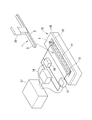
- FIG. 3 is a diagram illustrating an example of the configuration of the isoelectric focusing device 10. As shown in FIG. 3, the isoelectric focusing device 10 has a rectangular parallelepiped shape, and an elongated rectangular electrophoresis chamber 11 is formed at the center.
- a first electrode 12 that is in contact with the acidic side end of the sample-containing medium 2 is provided on one end side in the longitudinal direction of the electrophoresis chamber 11, and the basic side of the sample-containing medium 2 is provided on the other end side.
- the 2nd electrode 13 which the edge part contacts is installed.
- the first electrode 12 and the second electrode 13 are connected to a power source 14.
- the voltage between the first electrode 12 and the second electrode 13 is controlled by the voltage control unit 17.
- the voltage control unit 17 includes detection values of an ammeter 15 that measures the current flowing through the first electrode 12 and the second electrode 13 and a voltmeter 16 that measures the voltage between the first electrode 12 and the second electrode 13. Entered.
- the isoelectric focusing device 10 includes a cover 18 for preventing the sample-containing medium 2 from being dried during electrophoresis.
- the IPG gel strip 1 is placed in the electrophoresis chamber 11 using a transporting clip 20, and a voltage is applied to the first electrode 12 and the second electrode 13 that are in contact with the IPG gel strip 1. This is done by applying.
- Isoelectric focusing is performed by, for example, protein-containing 8M Urea, 2M Thiourea, 4% CHAPS (3-[(3-Cholamidopropylo) dimethylaminopropansulfonate), 20 mM dithiothreitol, 0.5% AmphorGolte strip After the swelling, the voltage is applied.
- the voltage controller 17 converges the protein to the isoelectric point by gradually increasing the voltage.
- the voltage controller 17 may be maintained at 200 V for 5 minutes, 200 V to 1000 V for 5 minutes, 1000 V for 5 minutes, 1000 V to 6000 V for 10 minutes, and 6000 V for 5 minutes. To raise.
- isoelectric focusing the protein contained in the sample-containing medium 2 migrates in the longitudinal direction of the sample-containing medium 2 by a distance corresponding to each isoelectric point (pI).
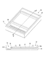
- FIG. 4 is a perspective view of a part of the second-dimensional electrophoresis apparatus 30 and a cross-sectional view taken along the line AA.
- the second-dimensional electrophoresis apparatus 30 includes a cathode buffer solution tank 31 for second-dimensional electrophoresis into which a cathode 31A is introduced, an anode buffer solution tank 32 for second-dimensional electrophoresis into which an anode 32A is introduced, and an upper substrate 33.
- a sample separation medium support plate 34 a sample loading section 35 into which the IPG gel strip 1 is introduced, and a sample separation section 36.
- the sample separation unit 36 is filled with a sample separation medium (gel) 37 for separating the sample after the first-dimensional electrophoresis.
- FIG. 5 is a diagram illustrating a state where the IPG gel strip 1 is introduced into the second-dimensional electrophoresis apparatus 30.
- the IPG gel strip 1 is placed on the sample loading unit 35 with the sample-containing medium 2 facing downward in the drawing.
- the cathode buffer solution tank 31 and the anode buffer solution tank 32 of the second-dimensional electrophoresis are filled with an electrophoresis buffer (a liquid reagent for conducting the gel and the electrode).
- the second-dimensional electrophoresis apparatus 30 includes a power source 40 and a voltage control unit 43.
- the voltage between the cathode 31A and the anode 32A is controlled by the voltage control unit 43.
- the voltage controller 43 receives detection values of an ammeter 41 that measures the current flowing through the cathode 31A and the anode 32A and a voltmeter 42 that measures the voltage between the cathode 31A and the anode 32A.
- the analyst Prior to performing the second-dimensional electrophoresis, the analyst analyzed the IPG gel strip 1 with, for example, 50 mM DTT, 500 mM Tris-HCl (pH 6.6), 4% SDS, 12.5% Glycerol, 0.005%. Deposit in an aqueous solution containing BPB for 5 minutes. Thereafter, the IPG gel strip 1 is placed on the sample loading unit 35, and for example, a desired voltage is applied at 20 mA between the cathode 31A and the anode 32A, and electrophoresis is performed for 30 minutes. Thereby, the protein migrated in the longitudinal direction of the IG gel strip 1 by isoelectric focusing can be migrated in the X direction in FIG.
- FIG. 6 is an example of a captured image obtained by imaging the sample separation medium (gel) 37 after two-dimensional electrophoresis is performed.
- a plurality of molecular weight markers 62 arranged in the vertical direction at the left end portion, and a plurality of isoelectric point markers 65 arranged in the left-right direction at the lower end portion (spots indicated by arrows in the drawing). Is visible to the analyst.
- “69” is a dye that has not reacted with the sample and has a large charge.
- “kDa” in FIG. 6 is a unit of kilodalton representing molecular weight.
- the analyst detects the isoelectric point marker and the molecular weight marker (step S120), and cuts the gel using a razor or the like (step S130).
- the analyst divides into a lattice shape (block shape) by a divided section along the isoelectric point direction (vertical direction in FIG. 6) and a divided section along the molecular weight direction (lateral direction in FIG. 6).
- the razor blade may be made of, for example, a resin, ceramic, metal, or the like that is harder than the gel, and a blade that is as thin as possible so as not to generate a gel piece when the gel is cut.
- FIG. 7A and 7B are diagrams showing the cut surface for cutting the gel 60 and the sample separation unit 36 after the block of the cut gel 60 is removed.
- FIG. 7A shows the state immediately after the gel 60 is cut
- FIG. 7B shows the state after the block is removed.
- the gel 60 is cut at the longitudinal cutting position 63 and the lateral cutting position 64 so that the molecular weight marker 62 and the isoelectric point marker 65 are not cut. Further, when the gel is cut, a cutting mark 67 in the vertical direction and a cutting mark 68 in the horizontal direction remain by cutting with a blade having a blade length wider than the block. By comparing the cutting trace generated by this cutting with the position of the molecular weight marker and the isoelectric point marker, the molecular weight position and the isoelectric point position of the cut position can be calculated.
- the analyst detects an isoelectric point marker and a molecular weight marker (step S140), and analyzes the sample for each block (step S150).
- the analyst for example, reduces the gel cut into a block shape to about 1 mm 3 , transfers it to a container such as a microtube or microplate, and digests the protein in the gel.
- the analyst adds 50 ⁇ L of 100% acetonitrile (CH 3 CN), 50 ⁇ L of 50 mM ammonium bicarbonate (NH 4 HCO 3 ), and is allowed to stand at room temperature for 15 minutes for destaining.
- the analyst added 100 ⁇ L of 100% CH 3 CN and allowed to stand at room temperature for 10 minutes, then added 10 mM (DTT) and 50 mM (NH 4 HCO 3 ) and incubated at 60 ° C. for 10 minutes. Let stand for 20 minutes to reduce the protein.
- the analyst performs alkylation by adding 30 ⁇ L of 50 mM iodoacetamide, 50 mM (NH 4 HCO 3 ) and allowing to stand at room temperature for 15 minutes.
- the analyst added 40 ⁇ L of 50 mM (NH 4 HCO 3 ) and left at room temperature for 15 minutes, and then added 100 ⁇ L of 100% CH 3 CN and allowed to stand at room temperature for 30 minutes. Drain and leave under nitrogen for 10 minutes.
- the analyst then adds 25 ⁇ l trypsin digest and incubates overnight at 30 ° C. to make the extracted peptide a sample for the mass spectrometer.
- the digestive fluid may be endopeptidase and is not limited to trypsin.
- the method of in-gel protein digestion is not limited to the said method.
- MASCOT, X! Can be used to identify proteins from peptide data detected using a mass spectrometer. This is done using software that collates with databases such as Tandem, OMASASA, Android, etc.
- the fragmentation treatment according to the present invention can be combined with a method for comparatively quantifying protein expression using MS-based proteomics.
- proteins are labeled with different labeling compounds between samples and then mixed and subjected to two-dimensional electrophoresis.
- the gel after two-dimensional electrophoresis is cut into blocks by this method and the peptides are extracted and analyzed with a mass spectrometer, the physical properties of the labeled proteins and peptides remain unchanged, but the mass or the tag molecules used for the labeling Since the mass is slightly different, each protein contained in each sample can be distinguished by the difference in mass even if analysis is performed at the same time, so that the difference in the amount of each protein can be compared.
- Labeled compounds used for labeling include SILAC, 15 N, 18 O, TNT, iTRAQ, etc., and SILAC, 15 N are metabolic labels, which allow cells to absorb amino acids and nitrates labeled with stable isotopes. Thus, proteins newly synthesized in cells are labeled.
- 18 O, TNT, and iTRAQ labels are chemical labels, and can be directly labeled by reacting the extracted protein or peptide with a stable isotope or a tag molecule containing a stable isotope in a test tube. Both the metabolically labeled sample and the directly labeled sample can be used in the present method.
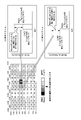
- FIG. 8 shows a method of displaying information obtained by combining a method of dividing a sample into blocks and a protein expression comparison using MS-based proteomics. Since many translated proteins are post-translationally modified, each protein is detected in multiple blocks when post-translational modification is performed.
- SILAC stable isotope labeling using amino acids in cell culture
- stable isotopes are labeled using different stable isotopes between samples. The points and molecular weights are almost the same and are detected in the same block, and their amounts can be compared with the MS peak amount (LC-MS spectrum in FIG. 8). Depending on these amounts, the difference can be clearly displayed by displaying the heat map in two dimensions as shown in FIG. In FIG. 8, if the protein is the same, the increase / decrease is expected to be the same in all detected compartments.
- proteins were prepared from cells cultured in a medium containing natural L-Lycine hydrochloride (Light) and cells cultured in a medium supplemented with 13 C 6 -L-Lycine hydrochloride (Heavy).
- the mass of the peptide obtained by dividing the gel into blocks and digesting the protein in the gel with trypsin is analyzed by a mass spectrometer.
- the protein can be identified by MASCOT.
- the number of blocks identified by post-translational modification of the protein spans multiple. It is possible to detect whether there is a difference in the translation amount of the protein between the samples to be compared and if there is a difference in post-translational modification, the difference is also detected for each block (FIG. 9).
- the medium containing the sample subjected to two-dimensional electrophoresis is divided into a lattice shape by a divided section along the isoelectric point direction and a divided section along the molecular weight direction.
- a target object separated by two-dimensional electrophoresis is detected with high sensitivity using a mass analyzer while having a specific isoelectric point region and a molecular weight region. be able to.
- the analysis method according to the second embodiment will be described.
- the isoelectric point and molecular weight of each divided block are grasped according to the reference display attached to the sample separation medium support plate. .
- FIG. 10A to FIG. 10C are diagrams showing how the sample separation medium support plate 70 that can estimate the molecular weight and isoelectric point of the cutting position is used.
- the sample separation medium support plate 70 is preliminarily drawn with a line (reference display) 73 such as a fluorescence that can be detected at the same time due to a difference in protein detection, such as a pen or laser processing machine. Yes.
- the line 73 is printed with, for example, a fluorescent dye having the same wavelength as the marker described above.
- FIG. 10B is a diagram illustrating a state where the gel is placed on the sample separation medium support plate 70.
- the gel is cut on the line 73 and the gel block is moved to a chamber or the like.
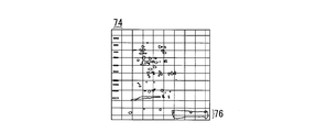
- molecular weight markers 74 and isoelectric point markers 76 that can be omitted are displayed for comparison.
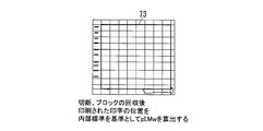
- FIG. 10C by comparing the positions of the molecular weight marker detected after the electrophoresis, the isoelectric point peptide marker, and the line 73, the accurate molecular weight and isoelectric point of the cleavage position can be grasped.
- An example of the estimated molecular weight and isoelectric point of each block is shown in FIG.
- a medium containing a sample subjected to two-dimensional electrophoresis is divided into a lattice shape along a dividing section along the isoelectric point direction and a dividing section along the molecular weight direction.
- a target object separated by two-dimensional electrophoresis is detected with high sensitivity using a mass analyzer while having a specific isoelectric point region and a molecular weight region. be able to.
- the present invention can be implemented in the following modes.
- (Appendix 1) The step of subjecting the target object to two-dimensional electrophoresis in an isoelectric point direction and a molecular weight direction substantially orthogonal to the isoelectric point direction (step S110), and a medium containing the target object subjected to the two-dimensional electrophoresis, A step (step S120) of dividing the divided section along the isoelectric point direction and a divided section along the molecular weight direction into a lattice shape (step S120), and a step of comparing the target object between the divided media (step S130). And an analysis method (FIG. 1).
- Appendix 3 The analysis method according to appendix 1, wherein a reference display (73) indicating a molecular weight and an isoelectric point is provided on a holding member (70) holding a medium containing the target object subjected to two-dimensional electrophoresis, An analysis method using a molecular weight and an isoelectric point grasped from the reference display in a step of comparing target objects.
- Appendix 4 The analysis method according to any one of appendices 1 to 3, wherein the amount of the identified target object is compared in the step of comparing the target objects.
- Appendix 5 The analysis method according to any one of appendices 1 to 4, wherein the target object is a protein, and the post-translational modification is performed by comparing the identified protein in the step of comparing the target object. Analytical method to compare the differences between the two.
- Appendix 6 The analysis method according to any one of appendices 1 to 5, wherein the target object is a protein, and in the step of comparing the target object, the protein contained in the divided medium is extracted, An analysis method for identifying the extracted protein using a mass spectrometer.
- Appendix 7 The analysis method according to any one of appendices 1 to 6, wherein the target object is a protein, and in the step of comparing the target object, the protein contained in the divided medium is converted into a proteolytic enzyme.
- Appendix 8 The analysis method according to any one of appendices 1 to 7, wherein the target object is a mixture of protein samples labeled with different stable isotopes.
- Appendix 9 The analysis method according to any one of appendices 1 to 7, wherein the target object is a protein, and in the step of comparing the target object, the protein contained in the fragmented medium is endopeptidase. Analytical method of cutting and comparing the amount of stable isotope protein different from protein identification using mass spectrometer.
- the present invention is suitably used as a means for separating a biological sample such as a protein by electrophoresis, cutting out a sample separation medium containing the separated biological sample, and identifying or analyzing the sample in the separation medium by a mass spectrometer. can do.
- Electrophoresis anode buffer tank 32A anode, 33 upper substrate, 34 sample separation medium support plate, 35 sample loading section, 36 sample separation section, 37 sample separation medium, 40 power supply, 41 current 42, Voltmeter, 43 Voltage controller, 60 Gel, 62 Molecular weight marker, 63 Vertical cutting position, 64 Horizontal cutting position, 65 Isoelectric point marker, 67 Vertical Cut trace, 68. Horizontal Direction of the cutting trace, 70 .. sample separating medium support plate, 73 .. line
Landscapes
- Health & Medical Sciences (AREA)
- Life Sciences & Earth Sciences (AREA)
- Chemical & Material Sciences (AREA)
- Molecular Biology (AREA)
- Biochemistry (AREA)
- Electrochemistry (AREA)
- Physics & Mathematics (AREA)
- Analytical Chemistry (AREA)
- Chemical Kinetics & Catalysis (AREA)
- General Health & Medical Sciences (AREA)
- General Physics & Mathematics (AREA)
- Immunology (AREA)
- Pathology (AREA)
- Dispersion Chemistry (AREA)
- Other Investigation Or Analysis Of Materials By Electrical Means (AREA)
- Investigating Or Analysing Biological Materials (AREA)
- Peptides Or Proteins (AREA)
Abstract
Description
本願は、2013年3月29日に、日本に出願された特願2013-071753号に基づき優先権を主張し、その内容をここに援用する。
<第1実施形態>
図1は、第1実施形態に係る分析方法の流れを示すフローチャートの一例である。まず、分析者は、IPG(固定化pH勾配ゲル)ゲルストリップ1を用意する(ステップS100)。図2は、IPGゲルストリップ1の外観形状の一例を示す図である。図2に示すように、IPGゲルストリップ1は、一次元電気泳動用のサンプル含有媒体2と、サンプル含有媒体2を支持する支持体3とを備える。サンプル含有媒体2は、等電点電気泳動によりサンプル(対象物体)が分離される媒体である。サンプルは、例えばタンパク質などの生体サンプルである。サンプル含有媒体2としては、二次元電気泳動の一次元目用ゲルとして用いられるものが利用でき、例えば、ポリアクリルアミド、アガロース、寒天、およびデンプンからなる群より選ばれるゲル化剤によりゲル化された固定化pH勾配(Immobilized pH gradient: IPG)ゲルなどが好適に用いられる。
支持体3としては、例えばプラスチック製の板やフィルムなどを用いることができる。
例えば、電圧制御部17は、例えば、200Vで5分間維持、200Vから1000Vまで5分間で上昇、1000Vで5分間維持、1000Vから6000Vまで10分間で上昇、6000Vで5分間維持といた流れで電圧を上昇させる。等電点電気泳動によって、サンプル含有媒体2に含まれるタンパク質が、サンプル含有媒体2の長手方向にそれぞれの等電点(pI)に応じた距離、泳動することになる。
以下、第2実施形態に係る分析方法について説明する。第2実施形態に係る分析方法では、等電点マーカーや分子量マーカーを用いるのではなく、サンプル分離媒体支持板に付された基準表示に従って、分断された各ブロックの等電点と分子量を把握する。
以上説明した第2実施形態の分析方法によれば、二次元電気泳動させたサンプルを含む媒体を、等電点方向に沿った分断面と、分子量方向に沿った分断面とで格子状に分断し、分断された媒体間でサンプルを比較するため、2次元電気泳動により分離された対象物体を、特定の等電点領域と分子量領域を持ったまま質量分析器を用いて高感度で検出することができる。
(付記1)
対象物体を、等電点方向と、該等電点方向に略直交する分子量方向とに二次元電気泳動させる工程(ステップS110)と、前記二次元電気泳動させた対象物体を含む媒体を、前記等電点方向に沿った分断面と、前記分子量方向に沿った分断面とで格子状に分断する工程(ステップS120)と、前記分断された媒体間で前記対象物体を比較する工程(ステップS130)と、を含む分析方法(図1)。
(付記2)
付記1記載の分析方法であって、前記二次元電気泳動が行われた状態で、基準となる複数の分子量および複数の等電点の位置に分析者によって視認可能なマーカー(62、65)が配置されるように、一次元目の電気泳動前および/または二次元目の電気泳動前に、既知の等電点と既知の分子量を持つマーカーを媒体に混入させる工程を更に含む、分析方法。
(付記3)
付記1記載の分析方法であって、前記二次元電気泳動させた対象物体を含む媒体を保持する保持部材(70)に、分子量および等電点を示す基準表示(73)がなされており、前記対象物体を比較する工程において、前記基準表示から把握される分子量および等電点を用いる、分析方法。
(付記4)
付記1から3のうちいずれか1記載の分析方法であって、前記対象物体を比較する工程において、同定された前記対象物体の量を比較する、分析方法。
(付記5)
付記1から4のうちいずれか1項記載の分析方法であって、前記対象物体は、タンパク質であり、記対象物体を比較する工程において、同定された前記タンパク質を比較することにより、翻訳後修飾の差を比較する、分析方法。
(付記6)
付記1から5のうちいずれか1項記載の分析方法であって、前記対象物体は、タンパク質であり、前記対象物体を比較する工程において、前記分断された媒体内に含まれるタンパク質を抽出し、質量分析装置を用いて前記抽出したタンパク質を同定する、分析方法。
(付記7)
付記1から6のうちいずれか1項記載の分析方法であって、前記対象物体は、タンパク質であり、前記対象物体を比較する工程において、前記分断された媒体内に含まれるタンパク質をタンパク質分解酵素で消化し、該消化した結果生じたペプチドを抽出し、質量分析装置を用いて前記抽出したタンパク質を同定する、分析方法。
(付記8)
付記1から7のうちいずれか1項記載の分析方法であって、前記対象物体は、異なる安定同位体で標識したタンパク質サンプルを混合したものである、分析方法。
(付記9)
付記1から7のうちいずれか1項記載の分析方法であって、前記対象物体は、タンパク質であり、前記対象物体を比較する工程において、前記分断された媒体内に含まれるタンパク質をエンドペプチダーゼで切断し、質量分析装置を用いてタンパク質の同定と異なる安定同位体タンパク質の量を比較する、分析方法。
Claims (9)
- 対象物体を、等電点方向と、該等電点方向に略直交する分子量方向とに二次元電気泳動させる工程と、
前記二次元電気泳動させた対象物体を含む媒体を、前記等電点方向に沿った分断面と、前記分子量方向に沿った分断面とで格子状に分断する工程と、
前記分断された媒体間で前記対象物体を比較する工程と、
を含む分析方法。 - 請求項1記載の分析方法であって、
前記二次元電気泳動が行われた状態で、基準となる複数の分子量および複数の等電点の位置に分析者によって視認可能なマーカーが配置されるように、一次元目の電気泳動前および/または二次元目の電気泳動前に、既知の等電点と既知の分子量を持つマーカーを前記媒体に混入させる工程を更に含む、
分析方法。 - 請求項1記載の分析方法であって、
前記二次元電気泳動させた対象物体を含む媒体を保持する保持部材に、分子量および等電点を示す基準表示がなされており、前記対象物体を比較する工程において、前記基準表示から把握される分子量および等電点を用いる、
分析方法。 - 請求項1から3のうちいずれか1記載の分析方法であって、
前記対象物体を比較する工程において、同定された前記対象物体の量を比較する、
分析方法。 - 請求項1から4のうちいずれか1項記載の分析方法であって、
前記対象物体は、タンパク質であり、
記対象物体を比較する工程において、同定された前記タンパク質を比較することにより、翻訳後修飾の差を比較する、
分析方法。 - 請求項1から5のうちいずれか1項記載の分析方法であって、
前記対象物体は、タンパク質であり、
前記対象物体を比較する工程において、前記分断された媒体内に含まれるタンパク質を抽出し、質量分析装置を用いて前記抽出したタンパク質を同定する、
分析方法。 - 請求項1から6のうちいずれか1項記載の分析方法であって、
前記対象物体は、タンパク質であり、
前記対象物体を比較する工程において、前記分断された媒体内に含まれるタンパク質をタンパク質分解酵素で消化し、該消化した結果生じたペプチドを抽出し、質量分析装置を用いて前記抽出したタンパク質を同定する、
分析方法。 - 請求項1から7のうちいずれか1項記載の分析方法であって、
前記対象物体は、異なる安定同位体で標識したタンパク質サンプルを混合したものである、
分析方法。 - 請求項1から7のうちいずれか1項記載の分析方法であって、
前記対象物体は、タンパク質であり、
前記対象物体を比較する工程において、前記分断された媒体内に含まれるタンパク質をエンドペプチダーゼで切断し、質量分析装置を用いてタンパク質の同定と異なる安定同位体タンパク質の量を比較する、
分析方法。
Priority Applications (2)
| Application Number | Priority Date | Filing Date | Title |
|---|---|---|---|
| CN201480016864.0A CN105074447A (zh) | 2013-03-29 | 2014-01-31 | 分析方法 |
| US14/779,713 US20160084798A1 (en) | 2013-03-29 | 2014-01-31 | Analysis method |
Applications Claiming Priority (2)
| Application Number | Priority Date | Filing Date | Title |
|---|---|---|---|
| JP2013-071753 | 2013-03-29 | ||
| JP2013071753A JP5569761B1 (ja) | 2013-03-29 | 2013-03-29 | 分析方法 |
Publications (1)
| Publication Number | Publication Date |
|---|---|
| WO2014156293A1 true WO2014156293A1 (ja) | 2014-10-02 |
Family
ID=51427246
Family Applications (1)
| Application Number | Title | Priority Date | Filing Date |
|---|---|---|---|
| PCT/JP2014/052245 Ceased WO2014156293A1 (ja) | 2013-03-29 | 2014-01-31 | 分析方法 |
Country Status (4)
| Country | Link |
|---|---|
| US (1) | US20160084798A1 (ja) |
| JP (1) | JP5569761B1 (ja) |
| CN (1) | CN105074447A (ja) |
| WO (1) | WO2014156293A1 (ja) |
Families Citing this family (1)
| Publication number | Priority date | Publication date | Assignee | Title |
|---|---|---|---|---|
| CN109243541B (zh) * | 2018-09-17 | 2019-05-21 | 山东省分析测试中心 | 质谱同位素精细结构与超精细结构的模拟方法及装置 |
Citations (9)
| Publication number | Priority date | Publication date | Assignee | Title |
|---|---|---|---|---|
| JPH09210961A (ja) * | 1996-02-07 | 1997-08-15 | Emuesu Kiki Kk | 電気泳動法および電気泳動用の泳動媒体 |
| US5968332A (en) * | 1990-12-13 | 1999-10-19 | Opplt; Jan J. | Discontinuous and nonsequential polymeric gel systems for separation of macromolecules |
| JP2004500567A (ja) * | 2000-02-08 | 2004-01-08 | ザ リージェンツ オブ ザ ユニバーシティ オブ ミシガン | タンパク質分離および提示 |
| JP2005069905A (ja) * | 2003-08-26 | 2005-03-17 | Hitachi Sci Syst Ltd | スポット切り出し装置 |
| US20070119712A1 (en) * | 2003-09-24 | 2007-05-31 | Agilent Technologies, Inc. | Electrophoretic separation of amphoteric molecules |
| WO2007073005A1 (ja) * | 2005-12-22 | 2007-06-28 | Keio University | メチル基転移反応調節物質 |
| JP2007524069A (ja) * | 2003-09-24 | 2007-08-23 | アジレント・テクノロジーズ・インク | フレームを使用した分子の抽出 |
| JP2009509127A (ja) * | 2005-08-01 | 2009-03-05 | ジョン・ジェギョン | アガロースゲル又はポリアクリルアミドゲル中のdna、rna、又はタンパク質断片を回収するシステム |
| JP2012007893A (ja) * | 2010-06-22 | 2012-01-12 | Toppan Printing Co Ltd | 電気泳動用アクリルアミドゲルカセット |
Family Cites Families (8)
| Publication number | Priority date | Publication date | Assignee | Title |
|---|---|---|---|---|
| GB9624927D0 (en) * | 1996-11-29 | 1997-01-15 | Oxford Glycosciences Uk Ltd | Gels and their use |
| US6554991B1 (en) * | 1997-06-24 | 2003-04-29 | Large Scale Proteomics Corporation | Automated system for two-dimensional electrophoresis |
| GB0006141D0 (en) * | 2000-03-14 | 2000-05-03 | Brax Group Ltd | Mass labels |
| AUPR522601A0 (en) * | 2001-05-25 | 2001-06-21 | Proteome Systems Ltd | Imaging means for excision apparatus |
| GB0209329D0 (en) * | 2002-04-24 | 2002-06-05 | Imp College Innovations Ltd | A device |
| JP4088869B2 (ja) * | 2002-05-10 | 2008-05-21 | 日本ビクター株式会社 | 固体撮像素子の欠陥画素検出装置及び固体撮像装置 |
| CN101233224A (zh) * | 2005-08-01 | 2008-07-30 | 郑在景 | 从琼脂糖凝胶或聚丙烯酰胺凝胶中回收dna、rna或蛋白质片段的系统 |
| US10107782B2 (en) * | 2008-01-25 | 2018-10-23 | ProteinSimple | Method to perform limited two dimensional separation of proteins and other biologicals |
-
2013
- 2013-03-29 JP JP2013071753A patent/JP5569761B1/ja not_active Expired - Fee Related
-
2014
- 2014-01-31 US US14/779,713 patent/US20160084798A1/en not_active Abandoned
- 2014-01-31 WO PCT/JP2014/052245 patent/WO2014156293A1/ja not_active Ceased
- 2014-01-31 CN CN201480016864.0A patent/CN105074447A/zh active Pending
Patent Citations (9)
| Publication number | Priority date | Publication date | Assignee | Title |
|---|---|---|---|---|
| US5968332A (en) * | 1990-12-13 | 1999-10-19 | Opplt; Jan J. | Discontinuous and nonsequential polymeric gel systems for separation of macromolecules |
| JPH09210961A (ja) * | 1996-02-07 | 1997-08-15 | Emuesu Kiki Kk | 電気泳動法および電気泳動用の泳動媒体 |
| JP2004500567A (ja) * | 2000-02-08 | 2004-01-08 | ザ リージェンツ オブ ザ ユニバーシティ オブ ミシガン | タンパク質分離および提示 |
| JP2005069905A (ja) * | 2003-08-26 | 2005-03-17 | Hitachi Sci Syst Ltd | スポット切り出し装置 |
| US20070119712A1 (en) * | 2003-09-24 | 2007-05-31 | Agilent Technologies, Inc. | Electrophoretic separation of amphoteric molecules |
| JP2007524069A (ja) * | 2003-09-24 | 2007-08-23 | アジレント・テクノロジーズ・インク | フレームを使用した分子の抽出 |
| JP2009509127A (ja) * | 2005-08-01 | 2009-03-05 | ジョン・ジェギョン | アガロースゲル又はポリアクリルアミドゲル中のdna、rna、又はタンパク質断片を回収するシステム |
| WO2007073005A1 (ja) * | 2005-12-22 | 2007-06-28 | Keio University | メチル基転移反応調節物質 |
| JP2012007893A (ja) * | 2010-06-22 | 2012-01-12 | Toppan Printing Co Ltd | 電気泳動用アクリルアミドゲルカセット |
Also Published As
| Publication number | Publication date |
|---|---|
| JP2014196913A (ja) | 2014-10-16 |
| CN105074447A (zh) | 2015-11-18 |
| US20160084798A1 (en) | 2016-03-24 |
| JP5569761B1 (ja) | 2014-08-13 |
Similar Documents
| Publication | Publication Date | Title |
|---|---|---|
| Westermeier et al. | Proteomics in practice: a guide to successful experimental design | |
| US6677114B1 (en) | Polypeptide fingerprinting methods and bioinformatics database system | |
| Görg et al. | 2‐DE with IPGs | |
| Colantonio et al. | The clinical application of proteomics | |
| Kim et al. | Gel-based proteomics in disease research: Is it still valuable? | |
| Klepárník et al. | Electrophoresis today and tomorrow: Helping biologists' dreams come true | |
| Campion et al. | Protein quantitation and analysis of purity | |
| Friedman | Quantitative proteomics for two-dimensional gels using difference gel electrophoresis | |
| Liu et al. | Micro-separation toward systems biology | |
| Anjo et al. | Unraveling mesenchymal stem cells’ dynamic secretome through nontargeted proteomics profiling | |
| Hietpas et al. | On-column and post-column derivatization for capillary electrophoresis with laser-induced fluorescence for the analysis of single cells | |
| Gao | Two-dimensional difference gel electrophoresis: a gel-based proteomic approach for protein analysis | |
| Nissum et al. | Analysis of human plasma proteins: a focus on sample collection and separation using free-flow electrophoresis | |
| JP5569761B1 (ja) | 分析方法 | |
| Guo et al. | A tunable isoelectric focusing via moving reaction boundary for two-dimensional gel electrophoresis and proteomics | |
| Meleady | 2D gel electrophoresis and mass spectrometry identification and analysis of proteins | |
| Gao | Analysis of protein changes using two-dimensional difference gel electrophoresis | |
| Chen | Revisit of imidazole-zinc reverse stain for protein polyacrylamide gel electrophoresis | |
| Holland | Two-Dye Versus Three-Dye DIGE for Comparative Testis Tissue Proteomic Analysis | |
| McGregor et al. | Proteomics and laser microdissection | |
| Marshall et al. | Spotting targets with 2D-DIGE proteomics | |
| Wildgruber et al. | Free-flow electrophoresis system for plasma proteomic applications | |
| JP5502151B2 (ja) | 電気泳動用器具、電気泳動装置、サンプル導入方法およびサンプル分離方法 | |
| Rabilloud et al. | Two-dimensional SDS-PAGE fractionation of biological samples for biomarker discovery | |
| Zuo et al. | Electrophoretic prefractionation for comprehensive analysis of proteomes |
Legal Events
| Date | Code | Title | Description |
|---|---|---|---|
| WWE | Wipo information: entry into national phase |
Ref document number: 201480016864.0 Country of ref document: CN |
|
| 121 | Ep: the epo has been informed by wipo that ep was designated in this application |
Ref document number: 14775904 Country of ref document: EP Kind code of ref document: A1 |
|
| WWE | Wipo information: entry into national phase |
Ref document number: 14779713 Country of ref document: US |
|
| NENP | Non-entry into the national phase |
Ref country code: DE |
|
| 122 | Ep: pct application non-entry in european phase |
Ref document number: 14775904 Country of ref document: EP Kind code of ref document: A1 |