WO2014155967A1 - Oil supply device for engine - Google Patents
Oil supply device for engine Download PDFInfo
- Publication number
- WO2014155967A1 WO2014155967A1 PCT/JP2014/001027 JP2014001027W WO2014155967A1 WO 2014155967 A1 WO2014155967 A1 WO 2014155967A1 JP 2014001027 W JP2014001027 W JP 2014001027W WO 2014155967 A1 WO2014155967 A1 WO 2014155967A1
- Authority
- WO
- WIPO (PCT)
- Prior art keywords
- oil
- engine
- hydraulic pressure
- pump
- valve
- Prior art date
Links
Images


Classifications
-
- F—MECHANICAL ENGINEERING; LIGHTING; HEATING; WEAPONS; BLASTING
- F01—MACHINES OR ENGINES IN GENERAL; ENGINE PLANTS IN GENERAL; STEAM ENGINES
- F01M—LUBRICATING OF MACHINES OR ENGINES IN GENERAL; LUBRICATING INTERNAL COMBUSTION ENGINES; CRANKCASE VENTILATING
- F01M1/00—Pressure lubrication
- F01M1/16—Controlling lubricant pressure or quantity
-
- F—MECHANICAL ENGINEERING; LIGHTING; HEATING; WEAPONS; BLASTING
- F01—MACHINES OR ENGINES IN GENERAL; ENGINE PLANTS IN GENERAL; STEAM ENGINES
- F01M—LUBRICATING OF MACHINES OR ENGINES IN GENERAL; LUBRICATING INTERNAL COMBUSTION ENGINES; CRANKCASE VENTILATING
- F01M1/00—Pressure lubrication
- F01M1/02—Pressure lubrication using lubricating pumps
- F01M2001/0207—Pressure lubrication using lubricating pumps characterised by the type of pump
- F01M2001/0246—Adjustable pumps
-
- F—MECHANICAL ENGINEERING; LIGHTING; HEATING; WEAPONS; BLASTING
- F02—COMBUSTION ENGINES; HOT-GAS OR COMBUSTION-PRODUCT ENGINE PLANTS
- F02D—CONTROLLING COMBUSTION ENGINES
- F02D13/00—Controlling the engine output power by varying inlet or exhaust valve operating characteristics, e.g. timing
- F02D13/02—Controlling the engine output power by varying inlet or exhaust valve operating characteristics, e.g. timing during engine operation
- F02D13/0223—Variable control of the intake valves only
- F02D13/0234—Variable control of the intake valves only changing the valve timing only
- F02D13/0238—Variable control of the intake valves only changing the valve timing only by shifting the phase, i.e. the opening periods of the valves are constant
-
- F—MECHANICAL ENGINEERING; LIGHTING; HEATING; WEAPONS; BLASTING
- F02—COMBUSTION ENGINES; HOT-GAS OR COMBUSTION-PRODUCT ENGINE PLANTS
- F02D—CONTROLLING COMBUSTION ENGINES
- F02D13/00—Controlling the engine output power by varying inlet or exhaust valve operating characteristics, e.g. timing
- F02D13/02—Controlling the engine output power by varying inlet or exhaust valve operating characteristics, e.g. timing during engine operation
- F02D13/06—Cutting-out cylinders
-
- F—MECHANICAL ENGINEERING; LIGHTING; HEATING; WEAPONS; BLASTING
- F02—COMBUSTION ENGINES; HOT-GAS OR COMBUSTION-PRODUCT ENGINE PLANTS
- F02D—CONTROLLING COMBUSTION ENGINES
- F02D17/00—Controlling engines by cutting out individual cylinders; Rendering engines inoperative or idling
- F02D17/02—Cutting-out
-
- F—MECHANICAL ENGINEERING; LIGHTING; HEATING; WEAPONS; BLASTING
- F02—COMBUSTION ENGINES; HOT-GAS OR COMBUSTION-PRODUCT ENGINE PLANTS
- F02D—CONTROLLING COMBUSTION ENGINES
- F02D41/00—Electrical control of supply of combustible mixture or its constituents
- F02D41/0002—Controlling intake air
- F02D2041/001—Controlling intake air for engines with variable valve actuation
- F02D2041/0012—Controlling intake air for engines with variable valve actuation with selective deactivation of cylinders
-
- F—MECHANICAL ENGINEERING; LIGHTING; HEATING; WEAPONS; BLASTING
- F02—COMBUSTION ENGINES; HOT-GAS OR COMBUSTION-PRODUCT ENGINE PLANTS
- F02D—CONTROLLING COMBUSTION ENGINES
- F02D41/00—Electrical control of supply of combustible mixture or its constituents
- F02D41/008—Controlling each cylinder individually
- F02D41/0087—Selective cylinder activation, i.e. partial cylinder operation
Definitions
- the present invention relates to an oil supply device that supplies engine oil from an oil pump to various parts of an engine for automobiles and the like, and particularly belongs to the field of oil pump control technology.
- the required oil pressure of the engine oil varies depending on the operating state of the engine (rotation speed, load, oil temperature, etc.). For example, if the oil temperature is high, the amount of leakage from the bearing portion or the like increases, making it difficult to increase the oil pressure. Therefore, it is necessary to increase the oil pressure as the oil temperature increases. Further, the engine oil for cooling the piston needs to have a high oil pressure because the required amount of oil increases as the engine speed increases. Furthermore, since the variable valve timing mechanism (VariablealValve Timing, abbreviated as VVT), the valve stop mechanism for the reduced cylinder operation, and the like are switched according to the operation state, it is necessary to change the hydraulic pressure at each switching.
- VVT VariablealValve Timing
- Patent Document 1 discloses a technique in which a hydraulic control valve (duty linear solenoid valve) is provided in a discharge passage of an oil pump and the hydraulic pressure of engine oil supplied to each part is controlled according to the operating state of the engine. .
- a hydraulic control valve duty linear solenoid valve
- the oil pump is a constant capacity type, and when the required oil pressure (oil amount) is small, the engine oil discharged by the oil pump is returned to the oil tank by the hydraulic control valve. Therefore, as a result, the work of the oil pump when discharging the returned amount of engine oil is wasted, and the effect of improving the fuel efficiency is low.
- a variable displacement oil pump is used as an oil pump for supplying an operating pressure for operating a variable lift mechanism of an intake / exhaust valve, and a required discharge amount for obtaining a required lift characteristic of the valve is
- a technique is disclosed that is determined by the engine rotation speed, the engine load, and the oil temperature, and controls the discharge amount of the oil pump based on the total required discharge amount.
- Patent Document 2 does not satisfy the required oil pressure from each hydraulic actuator at the same time.
- the technique since the technique does not perform feedback control of the hydraulic pressure based on the detected value, the accuracy of the capacity control of the oil pump is low. Therefore, the effect of improving the fuel efficiency is insufficient.
- an object of the present invention is to further improve the fuel consumption of the engine by appropriately controlling the capacity of the variable displacement oil pump while ensuring the required oil pressure of each hydraulic actuator.
- an oil supply device for an engine includes a variable displacement oil pump, a plurality of hydraulic actuators connected to the pump through an oil passage, and a change in the capacity of the pump. And a pump control unit for controlling the oil discharge amount, a hydraulic pressure detection unit for detecting the oil pressure of the oil passage that changes in accordance with the discharge amount, and a request for each hydraulic actuator specified for each operating state of the engine
- a storage unit that stores a hydraulic pressure control map that defines a target hydraulic pressure to be set according to the operating state of the engine based on the highest required hydraulic pressure among the hydraulic pressures.
- the pump control unit reads the current target hydraulic pressure from the stored hydraulic pressure control map, changes the capacity of the pump so that the hydraulic pressure detected by the hydraulic pressure detection unit matches the read target hydraulic pressure, and Control the discharge rate.
- FIG. 1 It is a figure showing a schematic structure of an engine which is one embodiment of the present invention. It is sectional drawing which shows schematic structure of HLA with a valve stop function. It is side surface sectional drawing which shows schematic structure of VVT. It is a figure for demonstrating operation
- the engine 2 is an in-line four-cylinder gasoline engine in which the first to fourth cylinders are arranged in series (in a direction perpendicular to the paper surface) in series, and the cam caps 3 connected to each other in the vertical direction.
- a cylinder head 4, a cylinder block 5, a crankcase (not shown), and an oil pan 6 (see FIG. 4) are provided.
- Four cylinder bores 7 are formed in the cylinder block 5.
- a piston 8 is slidably provided in each cylinder bore 7.
- the piston 8 is connected to a crankshaft (not shown) rotatably supported on the crankcase by a connecting rod 10.
- a combustion chamber 11 defined by a cylinder bore 7 and a piston 8 is formed in the upper part of the cylinder block 5 for each cylinder.
- the cylinder head 4 is provided with an intake port 12 and an exhaust port 13 that open to the combustion chamber 11, and an intake valve 14 and an exhaust valve 15 that open and close the intake port 12 and the exhaust port 13 are provided in the ports 12 and 13. Yes.
- These intake and exhaust valves 14 and 15 are urged in the closing direction (upward in FIG. 1) by return springs 16 and 17, and cam portions 18a and 19a provided on the outer circumferences of the rotating camshafts 18 and 19, It is driven to open and close by swing arms 20 and 21 provided therebelow. That is, along with the rotation of the camshafts 18 and 19, the cam followers 20a and 21a that are rotatably provided at substantially the center portions of the swing arms 20 and 21 are pushed downward by the cam portions 18a and 19a.
- Hydraulic ⁇ ⁇ Lash ⁇ Adjuster As the pivot mechanism 25a of the swing arms 20 and 21 of the second and third cylinders in the center of the engine, a known hydraulic lash adjuster 24 (hereinafter referred to as Hydraulic ⁇ ⁇ Lash ⁇ Adjuster) that automatically adjusts the valve clearance to zero by hydraulic pressure. (Referred to as “HLA”).
- an HLA 25 (FIGS. 1 and 2) to which a valve stop function for stopping the opening and closing operations of the intake and exhaust valves 14 and 15 is added. Reference) is provided.
- This HLA 25 with a valve stop function in addition to the function of automatically adjusting the valve clearance to zero, similarly to the HLA 24, intake and exhaust of the first and fourth cylinders depending on whether the engine 2 is in a reduced cylinder operation or all cylinder operation. It also has a function of switching between opening and closing the valves 14 and 15.
- the HLA 25 opens and closes the intake and exhaust valves 14 and 15 of the first and fourth cylinders when the engine 2 is operating in all cylinders, while the intake and exhaust valves 14 of the first and fourth cylinders when the engine 2 is reduced in cylinders. , 15 is stopped.
- the HLA 25 has a valve stop mechanism 25b (FIG. 2) as a mechanism for stopping the opening / closing operation of the intake and exhaust valves 14, 15.
- the valve stop mechanism 25b corresponds to a “valve stop device” in the claims.
- the cylinder head 4 is provided with mounting holes 26 and 27 for inserting and mounting the lower ends of the HLA 24 and the HLA 25 with a valve stop function.
- the cylinder head 4 is provided with oil passages 61, 62, 63, 64 communicating with the mounting holes 26, 27 for the HLA 25 with a valve stop function.
- the oil passages 61 and 62 supply hydraulic pressure (operating pressure) for operating the valve stop mechanism 25b of the HLA 25, and the oil passages 63 and 64 are pivot mechanisms of the HLA 25.
- 25a automatically supplies hydraulic pressure for adjusting the valve clearance to zero.
- the cylinder block 5 is provided with a main gallery 54 that extends in the cylinder row direction within the side wall on the exhaust side of the cylinder bore 7.
- An oil jet 28 for cooling the piston communicating with the main gallery 54 is provided for each piston 8 in the vicinity of the lower side of the main gallery 54.
- the oil jet 28 has a nozzle portion 28 a disposed on the lower side of the piston 8, and engine oil (hereinafter simply referred to as “oil”) from the nozzle portion 28 a toward the back surface of the top portion of the piston 8. Is configured to inject fuel.
- the oil jet 28 corresponds to an “oil injection valve” in the claims.
- the oil showers 29 and 30 formed of pipes are provided above the camshafts 18 and 19, respectively.
- the oil for lubrication supplied from the oil showers 29, 30 is the cam portions 18a, 19a of the cam shafts 18, 19 below the oil showers 29, 30, and the swing arms 20, 21 and the cam followers 20a below. , 21a.
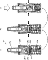
- valve stop mechanism 25b which is one of the hydraulic actuators, will be described with reference to FIG.
- the valve stop mechanism 25b is a cylinder-reduction operation that stops the opening / closing operation of the intake and exhaust valves 14 and 15 of the first and fourth cylinders according to the operation state of the engine 2, and all the HLAs 24 and 25 are normally operated. This is a mechanism for switching to full cylinder operation in which the cylinder intake and exhaust valves 14 and 15 are opened and closed.
- the HLA 25 with a valve stop function includes the pivot mechanism 25a and the valve stop mechanism 25b.
- the pivot mechanism 25a automatically adjusts the valve clearance to zero by hydraulic pressure, and since it has substantially the same configuration as the well-known HLA 24 used for the second and third cylinders, a description thereof will be omitted.
- the valve stop mechanism 25b includes a bottomed outer cylinder 251 that accommodates the pivot mechanism 25a so as to be slidable in the axial direction, and two through holes 251a that are provided to face each other on the side circumferential surface of the outer cylinder 251.
- a pair of lock pins 252 capable of switching the locked and unlocked pivot mechanism 25a, which can be moved in and out and axially slidable, and a lock spring that biases these lock pins 252 radially outward 253 and a lost motion spring 254 that is provided between the inner bottom portion of the outer cylinder 251 and the bottom portion of the pivot mechanism 25a and presses the pivot mechanism 25a above the outer cylinder 251 to urge it.
- both lock pins 252 come close to each other against the tensile force of the lock spring 253.
- the fitting between the lock pin 252 and the through-hole 251a of the outer cylinder 251 is released, and the upper pivot mechanism 25a is in an unlocked state in which it can move in the axial direction.
- VVT 32 changes the opening / closing timing of the intake valve 14
- VVT 33 changes the opening / closing timing of the exhaust valve 15.
- Both the VVT 32 for the intake valve 14 and the VVT 35 for the exhaust valve 15 have the same structure. That is, the VVT 32 (33) includes a substantially annular housing 321 (331) and a rotor 322 (332) accommodated in the housing 321 (331).
- the housing 321 (331) is connected to a cam pulley 323 (333) that rotates in synchronization with the crankshaft so as to be integrally rotatable, and the rotor 322 (332) is a camshaft that opens and closes the intake valve 14 (exhaust valve 15). 18 (19) so as to be integrally rotatable.
- a plurality of hydraulic chambers 326 (336) are formed.
- the VVTs 32 and 33 correspond to the “valve characteristic control device” described in the claims.
- oil supplied from the pump (oil pump) 36 via the first direction switching valve 34 is introduced into the hydraulic chambers 325 and 326 of the VVT 32.
- oil supplied from the pump 36 via the first direction switching valve 35 is introduced into the hydraulic chambers 335 and 336 of the VVT 33.
- the camshaft 18 (19) moves in the direction opposite to the rotation direction due to the hydraulic pressure.
- the opening and closing timing of the valve 15) is delayed.
- the camshaft 18 (19) moves in the rotational direction due to the hydraulic pressure, so that the opening / closing timing of the intake valve 14 (exhaust valve 15) is advanced.
- FIG. 3B shows a lift curve of the intake valve 14 and the exhaust valve 15 and illustrates a case where the opening / closing timing of the intake valve 14 is changed by the VVT 32.
- the opening / closing timing of the intake valve 14 is changed to the advance direction (see the arrow) by the VVT 32
- the opening period of the exhaust valve 15 and the opening period of the intake valve 14 is Overlap.
- the opening / closing timing of the intake valve 14 is changed to the retarded direction by the VVT 32, the opening period of the exhaust valve 15 and the opening period of the intake valve 14 (see the solid line) do not overlap, and stable combustion is performed during idle operation.
- the engine output can be improved during high-speed operation.
- the oil supply device 1 of the present embodiment is a device for supplying oil to the engine 2 described above, and is connected to the above-described pump 36 and the pump 36, and the pressurized oil is supplied to each part of the engine.
- An oil supply passage 50 is provided.
- the oil supply passage 50 includes a pipe, a passage formed in the cylinder block 5, the cylinder head 4, and the like.
- the oil supply passage 50 communicates with the pump 36, a first communication path 51 extending from the oil pan 6 to the branch point 54 a in the cylinder block 5, a main gallery 54 extending in the cylinder row direction in the cylinder block 5, and the main gallery 54.
- a second communication path 52 extending from the upper branching point 54 b to the cylinder head 4, a third communication path 53 extending in the horizontal direction between the intake side and the exhaust side in the cylinder head 4, and a second communication path in the cylinder head 4.
- a plurality of oil passages 61 to 69 branched from the three-way passage 53 are provided.
- the pump 36 is a known variable displacement oil pump, and is driven by rotation of a crankshaft (not shown).
- the pump 36 is formed so that one end side is open, and has a housing 361 including a pump body having a U-shaped cross section having a pump accommodating chamber formed in a columnar space therein and a cover member that closes the opening of the pump body.
- a drive shaft 362 that is rotatably supported by the housing 361 and that is driven to rotate by a crankshaft through the substantially central portion of the pump housing chamber, and is rotatably accommodated in the pump housing chamber so that the central portion serves as a drive shaft.
- a pump element comprising a coupled rotor 363 and a vane 364 which is housed in a plurality of slits radially formed in the outer peripheral portion of the rotor 363, and the rotor 363 is disposed on the outer peripheral side of the pump element.
- a pump chamber that is arranged eccentrically with respect to the center of rotation and is a plurality of hydraulic oil chambers together with the rotor 363 and the adjacent vane 364 65, a spring 367 that is housed in the pump body and is a biasing member that constantly biases the cam ring 366 in a direction in which the eccentric amount of the cam ring 366 increases with respect to the rotation center of the rotor 363, and the rotor 363.
- the housing 361 includes a suction port 361 a that supplies oil to the internal pump chamber 365 and a discharge port 361 b that discharges oil from the pump chamber 365.
- a pressure chamber 369 defined by the inner peripheral surface of the housing 361 and the outer peripheral surface of the cam ring 366 is formed inside the housing 361, and an introduction hole 369 a that opens to the pressure chamber 369 is provided.
- the pump 36 introduces oil into the pressure chamber 369 from the introduction hole 369 a, so that the cam ring 366 swings with respect to the fulcrum 361 c, and the rotor 363 is eccentric relative to the cam ring 366. It is configured to increase capacity.
- An oil strainer 39 facing the oil pan 6 is connected to the suction port 361a of the pump 36.
- An oil filter 37 and an oil cooler 38 are disposed in order from the upstream side to the downstream side in the first communication path 51 communicating with the discharge port 361b of the pump 36, and the oil stored in the oil pan 6 is stored in the oil strainer.
- the pump is pumped up by a pump 36 through 39, filtered by an oil filter 37, cooled by an oil cooler 38, and then introduced into a main gallery 54 in the cylinder block 5.
- the main gallery 54 supplies oil to oil jets 28 for injecting cooling oil to the back side of the four pistons 8 and metal bearings arranged in five main journals that rotatably support the crankshaft.
- the oil supply part 41 communicates with an oil supply part 42 that supplies oil to a metal bearing disposed on a crank pin of a crankshaft that rotatably connects four connecting rods. Is always supplied.
- oil is supplied from the introduction hole 369 a to the pressure chamber 369 of the pump 36 via the oil supply portion 43 that supplies oil to the hydraulic chain tensioner and the linear solenoid valve 49 in order.
- An oil passage 40 to be supplied is provided.
- the oil passage 68 branched from the branch point 53a of the third communication passage 53 is connected to the advance hydraulic chamber 336 of the VVT 33 for changing the opening / closing timing of the exhaust valve 15 and the delay through the first direction switching valve 35 on the exhaust side.
- the angle hydraulic chamber 335 communicates with the first hydraulic pressure chamber 336 and the retard hydraulic chamber 335 by operating the first direction switching valve 35.
- An oil passage 66 that branches from a branch point 64 a of the oil passage 64 communicates with an oil shower 30 that supplies lubricating oil to the exhaust-side swing arm 21, and oil is constantly supplied to the oil passage 66.
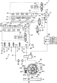
- the oil passage 64 includes an oil supply unit 45 (see a white triangle in FIG.
- the structure on the intake side is the same. That is, the oil passage 67 branched from the branch point 53c of the third communication passage 53 is connected to the advance hydraulic chamber 326 of the VVT 32 for changing the opening / closing timing of the intake valve 14 via the first direction switching valve 34 on the intake side.
- the retard hydraulic chamber 325 communicates with the retard hydraulic chamber 325.
- An oil passage 65 that branches from a branch point 63a of the oil passage 63 communicates with an oil shower 29 that supplies lubricating oil to the swing arm 20 on the intake side.
- the oil passage 63 branched from the branch point 53d of the third communication passage 53 is an oil supply portion 44 that supplies oil to a metal bearing disposed in the cam journal of the intake side camshaft 18 (see the white triangle in FIG. 4).
- HLA 24 see the black triangle in FIG. 4
- HLA 25 with valve stop function see the white ellipse in FIG. 4
- a check valve 48 that restricts the direction of oil flow in only one direction from the upstream side to the downstream side is provided in the oil passage 69 that branches from the branch point 53 c of the third communication passage 53.
- the oil passage 69 branches at a branch point 69 a on the downstream side of the check valve 48, and the exhaust side and intake side second direction switching valves 46, 47 and the oil passages 61, 62 pass through the exhaust side and intake side.
- Each of the valve stop mechanisms 25b of the HLA 25 is in communication with the valve stop mechanism 25b. By operating the second direction switching valves 46 and 47, oil is supplied to each valve stop mechanism 25b.
- a hydraulic pressure sensor 70 for detecting hydraulic pressure is provided between the check valve 48 on the oil passage 69 and the branch point 53c. The hydraulic pressure sensor 70 corresponds to a “hydraulic pressure detection unit” in the claims.
- Lubricating and cooling oil supplied to the metal bearings, oil jets 28, oil showers 29, 30 and the like that rotatably support the crankshaft and camshafts 18, 19 are drained (not shown) after cooling and lubrication.
- the oil is dropped into the oil pan 6 through the oil passage and circulated.
- the engine operating state is detected by various sensors.
- the rotation angle of the crankshaft is detected by the crank position sensor 71, and the engine rotation speed is calculated based on the detection signal.
- the opening of the throttle valve is detected by the throttle position sensor 72, and the engine load is calculated based on the detection signal.
- the oil temperature sensor 73 and the hydraulic pressure sensor 70 detect the temperature and pressure of the engine oil, respectively.
- the rotational angle of the camshafts 18 and 19 is detected by a cam angle sensor 74 provided in the vicinity of the camshafts 18 and 19, and the operating angles of the VVTs 32 and 33 are detected based on the detection signals.
- the water temperature sensor 75 detects the water temperature of the cooling water that cools the engine 2.
- the controller 100 includes a microcomputer and the like, and includes a signal input unit that inputs detection signals from various sensors (crank position sensor 71, throttle position sensor 72, oil temperature sensor 73, oil pressure sensor 70, etc.), and arithmetic processing related to control. Required for control, a signal output unit for outputting a control signal to a device to be controlled (first direction switching valves 34, 35, second direction switching valves 46, 47, linear solenoid valve 49, etc.) And a storage unit that stores various programs and data (such as a hydraulic control map and a duty ratio map described later).
- the linear solenoid valve 49 is a valve for controlling the discharge amount from the pump 36 in accordance with the operating state of the engine. Oil is supplied to the pressure chamber 369 of the pump 36 when the linear solenoid valve 49 is opened.
- the controller 100 controls the discharge amount (flow rate) of the pump 36 by driving the linear solenoid valve 49. That is, the controller 100 has a function as a “pump control unit” in the claims. Since the configuration of the linear solenoid valve 49 itself is well known, further detailed description is omitted.
- the linear solenoid valve 49 is driven in accordance with the duty ratio control signal sent from the controller 100 based on the operating state of the engine 2, and the hydraulic pressure supplied to the pressure chamber 369 of the pump 36 is controlled.
- the By the hydraulic pressure of the pressure chamber 369 the amount of eccentricity of the cam ring 366 is controlled and the amount of change in the internal volume of the pump chamber 365 is adjusted, whereby the discharge amount (flow rate) of the pump 36 is controlled. That is, the capacity of the pump 36 is controlled by the duty ratio.
- the flow rate (discharge amount) of the pump 36 is proportional to the engine rotational speed.
- the duty ratio represents the ratio of the energization time to the linear solenoid valve with respect to the time of one cycle, as shown in the figure, the hydraulic pressure to the pressure chamber 369 of the pump 36 increases as the duty ratio increases. The slope of the flow rate of the pump 36 is reduced.
- the controller 100 controls the VVTs 32 and 33 by driving the first direction switching valves 34 and 35, and drives the second direction switching valves 46 and 47 to drive the HLA 25 with a valve stop function (valve stop mechanism 25b). ) To control.
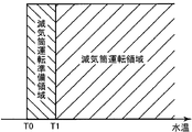
- the reduced-cylinder operation or all-cylinder operation of the engine is switched according to the operating state of the engine. That is, the reduced cylinder operation is executed when the engine operating state ascertained from the engine rotation speed, the engine load, and the coolant temperature of the engine is within the reduced cylinder operation region shown in the figure.
- a reduced cylinder operation preparation area is provided adjacent to the reduced cylinder operation area, and when the engine is in the reduced cylinder operation preparation area, the reduced cylinder operation is executed.
- the hydraulic pressure is increased in advance toward the required hydraulic pressure of the valve stop mechanism.
- all-cylinder operation is executed.
- the reduced cylinder operation when the engine rotation speed is increased by accelerating at a predetermined engine load, if the engine rotation speed is less than V1, all cylinder operation is performed, and if the engine rotation speed is V1 or more and less than V2, In preparation for the reduced cylinder operation, when the engine speed becomes V2 or more, the reduced cylinder operation is performed. Further, for example, when the engine speed is decreased by decelerating with a predetermined engine load, all cylinder operation is performed when the engine speed is V4 or more, and when the engine speed is V3 or more and less than V4, the reduced cylinder operation is performed. When preparation is made and the engine speed becomes V3 or less, the reduced cylinder operation is performed.
- this reduced-cylinder operation preparation area is not provided, when switching from all-cylinder operation to reduced-cylinder operation, the hydraulic pressure is increased to the required hydraulic pressure of the valve stop mechanism after the engine operating state enters the reduced-cylinder operation area. become. However, if this is done, the time for performing the reduced cylinder operation is shortened by the time required for the hydraulic pressure to reach the required oil pressure, so the time for performing the reduced cylinder operation is shortened and the fuel efficiency of the engine is reduced.
- a reduced cylinder operation preparation region is provided adjacent to the reduced cylinder operation region, and the hydraulic pressure is increased in advance in the reduced cylinder operation preparation region.
- a target hydraulic pressure map (see FIG. 7A) is set so as to eliminate a loss for the time required to reach the required hydraulic pressure.
- a region indicated by a one-dot chain line adjacent to the engine high load side with respect to the reduced cylinder operation region may be set as the reduced cylinder operation preparation region.
- the oil supply device 1 in this embodiment supplies oil to a plurality of hydraulic actuators by a single pump 36, and the required hydraulic pressure required by each hydraulic actuator changes depending on the operating state of the engine. Therefore, in order to obtain the required hydraulic pressure for all hydraulic operating devices in all engine operating states, the pump 36 has the highest required hydraulic pressure among the required hydraulic pressures of each hydraulic operating device for each engine operating state.
- the above oil pressure needs to be set as the target oil pressure.
- the required hydraulic pressures of the valve stop mechanism 25b, the oil jet 28, the journal of the crankshaft, etc., and the VVTs 32, 33 are relatively high among all hydraulic actuators. What is necessary is just to set target oil pressure so that it may satisfy
- the hydraulic actuators having a relatively high required oil pressure during the low-load operation of the engine are the VVTs 32 and 33, the metal bearing, and the valve stop mechanism 25b.
- the required oil pressure of each of these hydraulic actuators changes according to the operating state of the engine.
- the required oil pressures of the VVTs 32 and 33 (hereinafter referred to as VVT required oil pressure) are substantially constant at a predetermined engine speed (V0) or higher.
- the required oil pressure of the metal bearing (hereinafter referred to as a required metal oil pressure) increases as the engine speed increases.
- the required oil pressure of the valve stop mechanism 25b (hereinafter referred to as a valve stop required oil pressure) is substantially constant at a predetermined range of engine speed (V2 to V3).
- V2 to V3 a predetermined range of engine speed
- V2 to V3 a metal required oil pressure
- the VVT required oil pressure is the highest and the engine rotation speed is From V2 to V3
- the valve stop required oil pressure is the highest, when the engine speed is V3 to V6, the VVT required oil pressure is the highest, and when the engine speed is V6 or higher, the metal required oil pressure is the highest. Therefore, it is necessary to set the above-described highest required oil pressure as the reference target oil pressure as the target oil pressure of the pump 36 for each engine speed.
- the target hydraulic pressure is set to the valve stop request hydraulic pressure in preparation for the reduced cylinder operation. It is necessary to increase the pressure in advance toward For this reason, the target hydraulic pressure is corrected to be higher than the reference target hydraulic pressure at the rotation speeds (V1 to V2, V3 to V4). According to this, as described with reference to FIG. 6A, when the engine rotational speed reaches the engine rotational speed at which the cylinder reduction operation is performed, a loss corresponding to the time until the hydraulic pressure reaches the valve stop required hydraulic pressure is eliminated. Can improve fuel efficiency.
- the thick line in the range of engine speed V1 to V2 and the thick line in the range of V3 to V4 indicate the target oil pressure (corrected oil pressure) of the oil pump that has been increased by the above correction.
- the target hydraulic pressure is corrected so as to be higher than the reference target hydraulic pressure for the rotational speeds adjacent to the engine rotational speeds (V1 to V2, V3 to V4) that prepare for the reduced cylinder operation.
- the change in the hydraulic pressure becomes small (that is, the engine rotation speed) at the engine rotation speed (for example, V0, V1, V4) in which the required oil pressure tends to change rapidly with respect to the engine rotation speed.
- the target oil pressure when the engine speed is V0 or less, V0 to V1, and V4 to V5 is corrected to be higher than the reference target oil pressure so that the oil pressure gradually increases or decreases according to .
- the thick line in the range where the engine speed is V0 or less, the thick line in the range from V0 to V1, and the thick line in the range from V4 to V5 indicate the target oil pressure of the oil pump increased by the above correction. ing.
- the hydraulic actuators having relatively high required hydraulic pressures during high-load operation of the engine are VVTs 32 and 33, metal bearings, and oil jets 28.
- the required hydraulic pressure of each of these hydraulic actuators changes according to the operating state of the engine.
- the VVT required hydraulic pressure is substantially constant at a predetermined engine speed (V0 ′) or higher.
- the metal required hydraulic pressure increases as the engine speed increases.
- the oil jet 28 increases in accordance with the engine rotational speed up to a predetermined engine rotational speed, and is constant above the predetermined engine rotational speed.
- the target oil pressure is set to the reference target in the vicinity of the engine rotation speed (for example, V0 ′, V2 ′) in which the required oil pressure tends to change rapidly with respect to the engine rotation speed. It is better to compensate higher than hydraulic pressure.
- the thick line in the range where the engine rotational speed is V0 ′ or less and the thick line in the range from V1 ′ to V2 ′ indicate the target oil pressure of the oil pump increased by the correction.
- the oil pump target oil pressure shown in the figure changes in a polygonal line, it may change smoothly in a curved line.
- the target hydraulic pressure is set based on the required hydraulic pressures of the valve stop mechanism 25b, the oil jet 28, the metal bearing, and the VVTs 32, 33 having a relatively high required hydraulic pressure.
- the hydraulic actuator is not limited to these. What is necessary is just to set the target hydraulic pressure in consideration of the required hydraulic pressure, whatever the hydraulic actuator having a relatively high required hydraulic pressure.
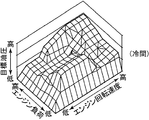
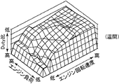
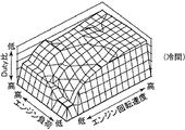
- the oil pump target oil pressure shown in FIGS. 7A and 7B uses the engine rotational speed as a parameter. Further, the oil pump target oil pressure is expressed in a three-dimensional graph using the engine load and oil temperature as parameters. 4 is a hydraulic control map shown in FIGS. That is, in this hydraulic control map, the target hydraulic pressure is preset based on the highest required hydraulic pressure among the required hydraulic pressures of each hydraulic actuator for each engine operating state (engine speed, engine load, and oil temperature). Is.
- FIG. 8A, 8B, and 8C show hydraulic control maps when the engine (oil temperature) is hot, warm, and cold, respectively.
- the controller 100 uses these hydraulic control maps properly according to the oil temperature. That is, when the engine is started and the engine is in a cold state (oil temperature is lower than T1), the controller 100 determines the engine operating state (engine rotation) based on the cold hydraulic control map shown in FIG. 8C. Read the target oil pressure according to the speed and engine load. When the engine is warmed up and the oil reaches a predetermined oil temperature T1 or higher, the target oil pressure is read based on the oil pressure control map during warming shown in FIG. 8B. Further, when the engine is completely warmed up and the oil becomes equal to or higher than a predetermined oil temperature T2 (> T1), the target oil pressure is read based on the high-temperature oil pressure control map shown in FIG. 8A.
- the target oil pressure is read using a hydraulic control map set in advance for each temperature range by dividing the oil temperature into three temperature ranges of high temperature, warm time, and cold time. More hydraulic control maps may be prepared by dividing the temperature range more finely. Further, when the oil temperature t is included in the temperature range (T1 ⁇ t ⁇ T2) targeted by one oil pressure control map (for example, the oil pressure control map at the time of warming), the target of the same value is used. Although the oil pressure is read, it may be changed according to the temperature.
- the duty ratio map is obtained by setting a target duty ratio for each engine operating state.
- the target duty ratio is obtained by reading the target oil pressure for each engine operating state (engine speed, engine load, oil temperature) from the above-mentioned oil pressure control map, and taking into account the flow path resistance of the oil passage based on the read target oil pressure. Then, a target discharge amount of oil supplied from the pump 36 is set, and the engine rotation speed (oil pump rotation speed) and the like are calculated based on the set target discharge amount.
- FIG. 9A, FIG. 9B, and FIG. 9C show duty ratio maps when the engine (oil temperature) is hot, warm, and cold, respectively.
- the controller 100 uses these duty ratio maps depending on the oil temperature. That is, since the engine is in a cold state when the engine is started, the controller 100 responds to the operating state of the engine (engine speed, engine load) based on the cold duty ratio map shown in FIG. 9C. Read the duty ratio. When the engine is warmed up and the oil reaches a predetermined oil temperature T1 or higher, the target duty ratio is read based on the duty ratio map during warming shown in FIG. 9B. Further, when the engine is completely warmed up and becomes equal to or higher than a predetermined oil temperature T2 (> T1), the target duty ratio is read based on the duty ratio map at high temperature shown in FIG. 9A.
- the oil temperature is divided into three temperature ranges of high temperature, warm time, and cold time, and the duty ratio is read using a duty ratio map set in advance for each temperature range.
- more duty ratio maps may be prepared by dividing the temperature range more finely, or the target duty ratio may be calculated by proportional conversion according to the oil temperature. This makes it possible to control the pump capacity with higher accuracy.
- step S1 After starting the engine 2, first, in order to grasp the operating state of the engine 2, the engine load, the engine speed and the oil temperature are read from various sensors (step S1).
- step S2 the duty ratio map stored in advance in the controller 100 is read, and the target duty ratio corresponding to the engine load, engine speed and oil temperature read in step S1 is read (step S2).
- step S3 The target duty ratio read in step S2 is compared with the current duty ratio (step S3).
- step S3 If it is determined in step S3 that the current duty ratio has reached the target duty ratio, the process proceeds to the next step S5.
- step S3 If it is determined in step S3 that the current duty ratio has not reached the target duty ratio, a control signal for matching the target duty ratio is output to the linear solenoid valve 49 (step S4), and the next step S5 is performed. move on.
- step S5 the current oil pressure is read from the oil pressure sensor 70 (step S5).
- a pre-stored hydraulic control map is read, and a target hydraulic pressure corresponding to the current engine operating state is read from the hydraulic control map (step S6).
- step S6 The target hydraulic pressure read in step S6 is compared with the current hydraulic pressure (step S7).
- step S7 If it is determined in step S7 that the current hydraulic pressure has not reached the target hydraulic pressure, a control signal for changing the target duty ratio of the linear solenoid valve 49 by a predetermined ratio is issued (step S8), and the process returns to step S5.
- step S7 If it is determined in step S7 that the current oil pressure has reached the target oil pressure, the engine load, engine speed, and oil temperature are read (step S9).
- step S10 it is determined whether or not the engine load, the engine speed and the oil temperature have changed. If it is determined that they have changed, the process returns to step S2, and if it has not been changed, the process returns to step S5. The above control is continued until the engine 2 is stopped.
- the flow rate control of the pump 36 described above is a combination of duty ratio feedforward control and hydraulic pressure feedback control. According to this flow rate control, responsiveness is improved by feedforward control and accuracy is improved by feedback control. Can be made compatible.
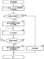
- step S11 After starting the engine 2, first, the engine load, the engine rotation speed, and the water temperature are read from various sensors in order to grasp the operating state of the engine (step S11).
- step S12 based on the read engine load, engine speed, and water temperature, it is determined whether the current engine operating condition satisfies the valve stop operating condition (is in the reduced cylinder operating range) (step S12).
- step S12 If it is determined in step S12 that the valve stop operation condition is not satisfied (not in the reduced cylinder operation region), four cylinder operation is performed (step S13).
- step S12 If it is determined in step S12 that the valve stop operation condition is satisfied, the first direction switching valves 34 and 35 connected to the VVTs 32 and 33 are operated (step S14).
- step S15 the current cam angle is read from the cam angle sensor 74 (step S15).
- the current operating angle of the VVTs 32 and 33 is calculated based on the read current cam angle, and it is determined whether this current operating angle is the target operating angle (step S16).
- step S16 If it is determined in step S16 that the current operating angle of the VVTs 32 and 33 is not the target operating angle ( ⁇ 1), the process returns to step S15. That is, the operation of the second direction switching valves 46 and 47 (control in step S17 described later) is prohibited until the target operating angle is reached.
- step S17 If it is determined in S16 that the target operating angle has been reached, the second direction switching valves 46 and 47 connected to the HLA 25 with a valve stop function are operated to perform a two-cylinder operation (step S17).
- the first direction switching valves 34 and 35 of the VVTs 32 and 33 are operated.
- the supply of oil to the advance hydraulic chambers 326 and 336 of the VVTs 32 and 33 is started, and the operating angles of the VVTs 32 and 33 change ( ⁇ 2 to ⁇ 1).
- the hydraulic pressure is lower than the valve stop request hydraulic pressure P1.
- the operation of the VVT 32, 33 is continued until the operating angle of the VVT 32, 33 reaches the target operating angle ⁇ 1. That is, the valve stop mechanism 25b is not operated while the oil pressure is lower than the valve stop request oil pressure P1.
- the operating angle of the VVT 32, 33 becomes the target operating angle ⁇ 1, and when the operation of the VVT 32, 33 is completed, the supply of oil to the advance hydraulic chambers 326, 336 of the VVT 32, 33 is terminated. Returns to the valve stop request hydraulic pressure P1.
- the second direction switching valves 46 and 47 are operated to supply hydraulic pressure to the valve stop mechanism 25b, and the engine is switched from the four-cylinder operation to the two-cylinder operation. Switch.
- the shift to the reduced cylinder (2 cylinder) operation means that the intake charge amount is increased by the advance angle control of the intake and exhaust valves 14 and 15. It means shifting to a reduced cylinder operation that takes charge of two cylinders. This leads to suppression of engine rotation fluctuations.
- FIG. 13 is an enlarged view of the configuration on the downstream side of the oil supply apparatus 1 in FIG. 4, in which the intake side and the exhaust side are simplified and shown.
- oil passages 67, 68, and 69 branch from a third communication passage 53 that leads to a main gallery 54 from which oil is discharged from the pump 36.
- the oil passages 67 and 68 communicate with the advance hydraulic chambers 326 and 336 and the retard hydraulic chambers 325 and 335 via the first direction switching valves 34 and 35, respectively.
- the oil passage 69 communicates with the valve stop mechanism 25b of the HLA 25 via the check valve 48 and the second direction switching valves 46 and 47.
- the check valve 48 is energized by a spring so as to open when the hydraulic pressure in the third communication passage 53 becomes equal to or higher than the required hydraulic pressure of the valve stop mechanism 25b, and allows oil flow only in one direction from the upstream side to the downstream side. regulate.
- the check valve 48 opens with a hydraulic pressure larger than the required hydraulic pressure of the VVTs 32 and 33.
- the hydraulic pressure in the third communication passage 53 is reduced.
- the check valve 48 provided in the oil passage 69 reduces the valve stop mechanism. Since the flow of oil from 25 b to the third communication passage 53 upstream of the check valve 48 on the oil passage 69 is blocked, the valve stop mechanism 25 b on the oil passage 69 downstream of the check valve 48 is used. The required hydraulic pressure is ensured.
- the highest required hydraulic pressure among the required hydraulic pressures of the hydraulic actuators such as the VVT 32, 33, the valve stop mechanism 25b, and the oil jet 28 is specified for each engine operating state.
- a target oil pressure corresponding to the engine operating state is preset and stored as a hydraulic control map, and the current target hydraulic pressure is set from this hydraulic control map.
- the required oil pressure such as the operating oil pressure and the oil injection pressure of each hydraulic actuator can be ensured by making the oil pressure of the oil passage coincide with the target oil pressure.
- the capacity of the pump 36 can be controlled with high accuracy. Therefore, further improvement in fuel consumption of the engine can be realized.
- a corrected hydraulic pressure that is higher than the highest required hydraulic pressure is set as a target hydraulic pressure based on the hydraulic control map. Therefore, by controlling the pump 36 based on this hydraulic pressure control map, the operation responsiveness of the valve stop mechanism 25b can be improved, and the shift to the reduced cylinder operation can be promoted, and the fuel consumption reduction effect can be enhanced.
- the VVTs 32 and 33 when the VVTs 32 and 33 are operated, in particular, when the oil discharge amount from the pump 36 is small because the engine 2 is rotating at a low speed, the VVTs 32 and 33 on the intake side and the exhaust side are operated simultaneously.
- the hydraulic pressure of the third communication passage 53 that communicates with 33 decreases, according to the present embodiment, while the VVTs 32 and 33 are operating during the reduced-cylinder operation, the check valve 48 provided in the oil passage causes Since the oil flow between the three-way passage 53 and the valve stop mechanism 25b is blocked, the oil pressure in the oil passage is prevented from temporarily decreasing due to the operation of the VVTs 32 and 33.
- the check valve 48 opens, so that the hydraulic pressure of the oil passage 69 becomes the same as the hydraulic pressure of the third communication path 53, A hydraulic pressure higher than the required hydraulic pressure can be supplied to the valve stop mechanism 25b.
- the check valve 48 is closed, so that the hydraulic pressure of the oil path 69 is influenced by the hydraulic pressure of the third communication path 53. Without being received, the required oil pressure of the valve stop mechanism 25b is maintained. Therefore, the malfunction of the valve stop mechanism 25b can be prevented only by adding a simple configuration in which a spring biased check valve 48 is provided in the oil passage 69 without performing special control.
- the valve stop mechanism 25b when the VVT 32, 33 is operating when the reduced cylinder operation is requested, the valve stop mechanism 25b is operated after the operation of the VVT 32, 33 is completed.
- the valve stop mechanism 25b operates after the lowered hydraulic pressure rises again, and it is possible to prevent the valve stop mechanism 25b from malfunctioning due to insufficient hydraulic pressure. Therefore, both the VVTs 32 and 33 and the valve stop mechanism 25b can be appropriately operated.
- the present invention is applied to an in-line four-cylinder gasoline engine, but the number of cylinders of the present invention may be any number, and may be applied to a diesel engine.
- the linear solenoid valve is used to control the pump 36.
- the present invention is not limited to this, and an electromagnetic control valve may be used.
- a check valve 48 is provided in the oil passage connected to the valve stop mechanism 25b, and the check valve 48 is opened at a pressure higher than the required hydraulic pressure of the valve stop mechanism 25b.
- a valve that opens at a hydraulic pressure higher than the hydraulic pressure is used, when there is a cylinder reduction request and a valve characteristic control request that cause the valve stop mechanism 25b and the VVT 32, 33 to overlap, the valve stop mechanism 25b malfunctions. If only the purpose of preventing this is the use of the check valve 48 that opens at a hydraulic pressure greater than the required hydraulic pressure of the VVTs 32 and 33, this objective can be achieved.
- a known electromagnetic control valve that can control opening and closing at a desired timing based on the operating angle of the VVTs 32 and 33 may be used.
- the valve stop mechanism is used as the check valve 48.
- This object can be achieved by using a valve that opens at a required oil pressure of 25b or higher.
- a known electromagnetic control valve that can control opening and closing at a desired timing based on the hydraulic pressure of the main gallery 54 may be used.
- the engine oil supply device includes a variable displacement oil pump, a plurality of hydraulic actuators connected to the pump through an oil passage, and the oil discharge amount by changing the capacity of the pump.
- the pump controller that controls, the oil pressure detector that detects the oil pressure of the oil passage that changes according to the discharge amount, and the highest demand among the required oil pressures of the hydraulic actuators that are specified for each operating state of the engine
- a storage unit that stores a hydraulic pressure control map that defines a target hydraulic pressure to be set according to the operating state of the engine based on the hydraulic pressure.
- the pump control unit reads the current target hydraulic pressure from the stored hydraulic pressure control map, changes the capacity of the pump so that the hydraulic pressure detected by the hydraulic pressure detection unit matches the read target hydraulic pressure, and Control the discharge rate.
- the highest required hydraulic pressure among the required hydraulic pressures of each hydraulic actuator is specified for each engine operating state, and based on this highest required hydraulic pressure, the target hydraulic pressure corresponding to the engine operating state is determined in advance. It is set and stored as a hydraulic control map, and the current target hydraulic pressure is set from this hydraulic control map, so the required hydraulic pressure of each hydraulic actuator is secured by matching the hydraulic pressure of the oil passage with this target hydraulic pressure can do. Further, since the oil pressure in the oil passage is feedback-controlled based on the detected value so as to realize the target oil pressure, the capacity of the pump can be controlled with high accuracy. Therefore, further improvement in fuel consumption of the engine can be realized.
- the oil supply device is preferably configured as at least one of an intake valve and an exhaust valve according to an operating state of the engine as the plurality of hydraulic operation devices.
- a hydraulically operated valve characteristic control device that changes the characteristics of the valve; a hydraulically operated valve stop device that stops at least one of an intake valve and an exhaust valve during reduced cylinder operation of the engine; and An oil injection valve for injecting oil to the piston.
- valve characteristic control device the valve stop device, and the oil injection valve are provided as the hydraulic operation device, the capacity of the variable displacement oil pump is appropriately controlled while ensuring the operation oil pressure and the oil injection pressure. it can.
- the hydraulic control map includes an engine rotation speed, an engine load, and an oil temperature as parameters indicating the engine operating state, and an engine operating region specified by the parameters includes the engine operating range.
- a corrected hydraulic pressure that is higher than the highest required hydraulic pressure is set as the target hydraulic pressure.
- a correction oil pressure higher than the highest required oil pressure is set as a target oil pressure in the oil pressure control map in an adjacent region of the engine operation region in which the valve stop device operates (the reduced cylinder operation is performed). Therefore, by controlling the pump based on this hydraulic pressure control map, the operation responsiveness of the valve stop device can be improved, the shift to the reduced cylinder operation can be promoted, and the fuel consumption reduction effect can be enhanced.
- the fuel consumption of the engine is further improved by appropriately controlling the capacity of the variable displacement oil pump while ensuring the required oil pressure of each hydraulic actuator. Since it can be improved, it is suitably used in the manufacturing industry of this type of engine.
Abstract
Description
Claims (3)
- 可変容量型のオイルポンプと、
前記ポンプと油路を介して接続された複数の油圧作動装置と、
前記ポンプの容量を変更してオイルの吐出量を制御するポンプ制御部と、
前記吐出量に応じて変わる前記油路の油圧を検出する油圧検出部と、
エンジンの運転状態ごとに特定される前記各油圧作動装置の要求油圧のうちで最も高い要求油圧に基づいて、エンジンの運転状態に応じて設定すべき目標油圧を定めた油圧制御マップを記憶する記憶部と、を備え、
前記ポンプ制御部は、前記記憶された油圧制御マップから現時点の目標油圧を読み取り、前記油圧検出部で検出された油圧が前記読み取った目標油圧に一致するように前記ポンプの容量を変更して前記吐出量を制御する
ことを特徴とするエンジンのオイル供給装置。 A variable displacement oil pump,
A plurality of hydraulic actuators connected to the pump via an oil passage;
A pump controller for controlling the oil discharge amount by changing the capacity of the pump;
A hydraulic pressure detection unit that detects a hydraulic pressure of the oil passage that changes according to the discharge amount;
A memory that stores a hydraulic pressure control map that defines a target hydraulic pressure that should be set according to the operating state of the engine, based on the highest required hydraulic pressure among the required hydraulic pressures of the hydraulic actuators that are specified for each operating state of the engine. And comprising
The pump control unit reads the current target hydraulic pressure from the stored hydraulic pressure control map, changes the capacity of the pump so that the hydraulic pressure detected by the hydraulic pressure detection unit matches the read target hydraulic pressure, and An oil supply device for an engine, characterized by controlling a discharge amount. - 前記エンジンは、複数の気筒を有する多気筒エンジンであり、
前記複数の油圧作動装置として、前記エンジンの運転状態に応じて吸気弁と排気弁のうち少なくとも一方の弁の特性を変更する油圧作動式の弁特性制御装置と、前記エンジンの減気筒運転時に吸気弁と排気弁のうち少なくとも一方の弁を停止する油圧作動式の弁停止装置と、前記エンジンの各ピストンにオイルを噴射するオイル噴射弁と、を備える
ことを特徴とする請求項1に記載のエンジンのオイル供給装置。 The engine is a multi-cylinder engine having a plurality of cylinders,
As the plurality of hydraulic operating devices, a hydraulically operated valve characteristic control device that changes a characteristic of at least one of an intake valve and an exhaust valve according to an operating state of the engine, and an intake air during a reduced cylinder operation of the engine 2. The hydraulically operated valve stop device for stopping at least one of the valve and the exhaust valve, and an oil injection valve for injecting oil to each piston of the engine. Engine oil supply device. - 前記油圧制御マップは、前記エンジンの運転状態を示すパラメータとして、エンジン回転速度、エンジン負荷及び油温を含み、
前記各パラメータから特定されるエンジンの運転領域が、前記弁停止装置が作動する運転領域の隣接領域である場合には、前記目標油圧として、前記最も高い要求油圧よりも高い補正油圧が設定される
ことを特徴とする請求項2に記載のエンジンのオイル供給装置。 The hydraulic control map includes an engine rotation speed, an engine load, and an oil temperature as parameters indicating the operating state of the engine,
When the engine operating region specified by each parameter is a region adjacent to the operating region in which the valve stop device operates, a corrected hydraulic pressure higher than the highest required hydraulic pressure is set as the target hydraulic pressure. The engine oil supply device according to claim 2, wherein
Priority Applications (3)
| Application Number | Priority Date | Filing Date | Title |
|---|---|---|---|
| DE112014001755.8T DE112014001755T5 (en) | 2013-03-29 | 2014-02-26 | Oil supply device for engine |
| CN201480013426.9A CN105189950B (en) | 2013-03-29 | 2014-02-26 | To the machine oil feeding mechanism of engine supply machine oil |
| US14/770,416 US10233797B2 (en) | 2013-03-29 | 2014-02-26 | Oil supply device for engine |
Applications Claiming Priority (2)
| Application Number | Priority Date | Filing Date | Title |
|---|---|---|---|
| JP2013073911A JP6163831B2 (en) | 2013-03-29 | 2013-03-29 | Engine oil supply device |
| JP2013-073911 | 2013-03-29 |
Publications (1)
| Publication Number | Publication Date |
|---|---|
| WO2014155967A1 true WO2014155967A1 (en) | 2014-10-02 |
Family
ID=51622990
Family Applications (1)
| Application Number | Title | Priority Date | Filing Date |
|---|---|---|---|
| PCT/JP2014/001027 WO2014155967A1 (en) | 2013-03-29 | 2014-02-26 | Oil supply device for engine |
Country Status (5)
| Country | Link |
|---|---|
| US (1) | US10233797B2 (en) |
| JP (1) | JP6163831B2 (en) |
| CN (1) | CN105189950B (en) |
| DE (1) | DE112014001755T5 (en) |
| WO (1) | WO2014155967A1 (en) |
Families Citing this family (24)
| Publication number | Priority date | Publication date | Assignee | Title |
|---|---|---|---|---|
| US20160061071A1 (en) * | 2014-08-27 | 2016-03-03 | Hyundai Motor Company | Bypass apparatus of oil-cooler and controlling method thereof |
| JP6330700B2 (en) * | 2015-03-05 | 2018-05-30 | マツダ株式会社 | Engine oil supply device |
| JP6319194B2 (en) * | 2015-06-08 | 2018-05-09 | マツダ株式会社 | Engine oil supply device |
| JP6436056B2 (en) * | 2015-10-30 | 2018-12-12 | 株式会社デンソー | Engine control device |
| JP6319336B2 (en) * | 2016-01-21 | 2018-05-09 | マツダ株式会社 | Engine oil supply device |
| JP6308230B2 (en) * | 2016-02-23 | 2018-04-11 | マツダ株式会社 | Engine oil supply control device |
| JP6414100B2 (en) * | 2016-02-23 | 2018-10-31 | マツダ株式会社 | Engine oil supply device |
| JP6319342B2 (en) * | 2016-02-23 | 2018-05-09 | マツダ株式会社 | Engine oil supply control device |
| JP6308229B2 (en) | 2016-02-23 | 2018-04-11 | マツダ株式会社 | Engine oil supply control device |
| JP6278049B2 (en) * | 2016-03-03 | 2018-02-14 | マツダ株式会社 | Engine oil supply device |
| DE102017112566A1 (en) * | 2016-06-09 | 2017-12-14 | Ford Global Technologies, Llc | SYSTEM AND METHOD FOR OPERATING A MACHINE OIL PUMP |
| US10208687B2 (en) * | 2016-06-09 | 2019-02-19 | Ford Global Technologies, Llc | System and method for operating an engine oil pump |
| JP6308251B2 (en) * | 2016-07-20 | 2018-04-11 | マツダ株式会社 | Engine oil supply device |
| JP6296119B2 (en) * | 2016-08-24 | 2018-03-20 | マツダ株式会社 | Engine hydraulic control system |
| JPWO2018078815A1 (en) * | 2016-10-28 | 2019-06-27 | マツダ株式会社 | Control device of engine with variable valve timing mechanism |
| US10077726B2 (en) * | 2016-12-21 | 2018-09-18 | Ford Global Technologies, Llc | System and method to activate and deactivate engine cylinders |
| JP6460140B2 (en) * | 2017-03-15 | 2019-01-30 | マツダ株式会社 | Engine control apparatus and control method |
| EP3388644A1 (en) * | 2017-04-13 | 2018-10-17 | Volvo Truck Corporation | A method for controlling the oil pressure of an oil pump in a combustion engine and on oil pressure arrangement |
| JP6468449B2 (en) * | 2017-04-27 | 2019-02-13 | マツダ株式会社 | Engine control device |
| CN108386248B (en) * | 2018-01-29 | 2019-11-05 | 广州汽车集团股份有限公司 | A kind of engine oil method for controlling pump and device |
| JP2019157812A (en) * | 2018-03-16 | 2019-09-19 | 日立オートモティブシステムズ株式会社 | Control device of variable capacity oil pump and control method |
| DE102019101257A1 (en) * | 2019-01-18 | 2020-07-23 | Bayerische Motoren Werke Aktiengesellschaft | Valve train for an internal combustion engine with a variable camshaft control |
| DE102019206474A1 (en) * | 2019-05-06 | 2020-11-12 | Ford Global Technologies, Llc | Cylinder-specific engine cooling |
| DE102022209422A1 (en) | 2022-09-09 | 2024-03-14 | Volkswagen Aktiengesellschaft | Operating method for operating an oil pump control valve |
Citations (4)
| Publication number | Priority date | Publication date | Assignee | Title |
|---|---|---|---|---|
| JPH02245408A (en) * | 1989-03-17 | 1990-10-01 | Mazda Motor Corp | Valve timing control device for engine |
| JPH1082308A (en) * | 1996-09-06 | 1998-03-31 | Honda Motor Co Ltd | Drive unit of hydraulic actuator |
| JPH11189073A (en) * | 1997-12-25 | 1999-07-13 | Nissan Motor Co Ltd | Fluid pressure control device for hybrid vehicle |
| JP2008286063A (en) * | 2007-05-16 | 2008-11-27 | Toyota Motor Corp | Lubricating device of internal combustion engine |
Family Cites Families (7)
| Publication number | Priority date | Publication date | Assignee | Title |
|---|---|---|---|---|
| JP3084641B2 (en) | 1992-03-23 | 2000-09-04 | ヤマハ発動機株式会社 | Engine lubricant supply device |
| JP2002309916A (en) | 2001-04-13 | 2002-10-23 | Toyota Motor Corp | Variable valve lift mechanism for internal combustion engine |
| US6889634B1 (en) | 2004-04-16 | 2005-05-10 | Borgwarner Inc. | Method of providing hydraulic pressure for mechanical work from an engine lubricating system |
| DE102007024129A1 (en) | 2007-05-24 | 2008-12-04 | Continental Automotive Gmbh | Method and apparatus for oil circulation management in an internal combustion engine |
| JP5364606B2 (en) * | 2010-01-29 | 2013-12-11 | 日立オートモティブシステムズ株式会社 | Vane pump |
| JP5724332B2 (en) * | 2010-12-01 | 2015-05-27 | マツダ株式会社 | Engine oiling device |
| DE102012200279A1 (en) * | 2012-01-11 | 2013-07-11 | Ford Global Technologies, Llc | Method and apparatus for operating a lubrication system of an internal combustion engine |
-
2013
- 2013-03-29 JP JP2013073911A patent/JP6163831B2/en not_active Expired - Fee Related
-
2014
- 2014-02-26 DE DE112014001755.8T patent/DE112014001755T5/en active Pending
- 2014-02-26 WO PCT/JP2014/001027 patent/WO2014155967A1/en active Application Filing
- 2014-02-26 US US14/770,416 patent/US10233797B2/en active Active
- 2014-02-26 CN CN201480013426.9A patent/CN105189950B/en not_active Expired - Fee Related
Patent Citations (4)
| Publication number | Priority date | Publication date | Assignee | Title |
|---|---|---|---|---|
| JPH02245408A (en) * | 1989-03-17 | 1990-10-01 | Mazda Motor Corp | Valve timing control device for engine |
| JPH1082308A (en) * | 1996-09-06 | 1998-03-31 | Honda Motor Co Ltd | Drive unit of hydraulic actuator |
| JPH11189073A (en) * | 1997-12-25 | 1999-07-13 | Nissan Motor Co Ltd | Fluid pressure control device for hybrid vehicle |
| JP2008286063A (en) * | 2007-05-16 | 2008-11-27 | Toyota Motor Corp | Lubricating device of internal combustion engine |
Also Published As
| Publication number | Publication date |
|---|---|
| CN105189950B (en) | 2018-01-05 |
| US20160010519A1 (en) | 2016-01-14 |
| JP6163831B2 (en) | 2017-07-19 |
| US10233797B2 (en) | 2019-03-19 |
| JP2014199011A (en) | 2014-10-23 |
| DE112014001755T5 (en) | 2015-12-10 |
| CN105189950A (en) | 2015-12-23 |
Similar Documents
| Publication | Publication Date | Title |
|---|---|---|
| WO2014155967A1 (en) | Oil supply device for engine | |
| JP6123575B2 (en) | Multi-cylinder engine controller | |
| JP6217236B2 (en) | Control device and control method for multi-cylinder engine | |
| JP5966999B2 (en) | Multi-cylinder engine controller | |
| JP6187416B2 (en) | Engine oil supply device | |
| JP6213064B2 (en) | Engine control device | |
| JP6052205B2 (en) | Engine valve timing control device | |
| JP6160539B2 (en) | Engine control device | |
| JP6094430B2 (en) | Engine control device | |
| JP2015194131A (en) | Engine control device | |
| JP6094545B2 (en) | Engine oil supply device | |
| KR101204604B1 (en) | Variable valve device for an internal combustion engine | |
| JP6123726B2 (en) | Engine control device | |
| KR101110993B1 (en) | Variable valve device for internal combustion engine | |
| WO2018078815A1 (en) | Control device of engine with variable valve timing mechanism | |
| JP6156182B2 (en) | Multi-cylinder engine controller | |
| JP6020307B2 (en) | Multi-cylinder engine controller | |
| JP6146341B2 (en) | Engine valve timing control device | |
| JP6350635B2 (en) | Engine control device with variable valve timing mechanism | |
| JP6315061B1 (en) | Automotive engine with variable valve timing mechanism | |
| JP2017180240A (en) | Control device for variable displacement oil pump | |
| JP6350476B2 (en) | Engine oil supply device | |
| JP2018159339A (en) | Control device of engine |
Legal Events
| Date | Code | Title | Description |
|---|---|---|---|
| WWE | Wipo information: entry into national phase |
Ref document number: 201480013426.9 Country of ref document: CN |
|
| 121 | Ep: the epo has been informed by wipo that ep was designated in this application |
Ref document number: 14776077 Country of ref document: EP Kind code of ref document: A1 |
|
| WWE | Wipo information: entry into national phase |
Ref document number: 14770416 Country of ref document: US |
|
| WWE | Wipo information: entry into national phase |
Ref document number: 112014001755 Country of ref document: DE Ref document number: 1120140017558 Country of ref document: DE |
|
| 122 | Ep: pct application non-entry in european phase |
Ref document number: 14776077 Country of ref document: EP Kind code of ref document: A1 |