WO2014155880A1 - Printer paper-cutting device - Google Patents
Printer paper-cutting device Download PDFInfo
- Publication number
- WO2014155880A1 WO2014155880A1 PCT/JP2013/084730 JP2013084730W WO2014155880A1 WO 2014155880 A1 WO2014155880 A1 WO 2014155880A1 JP 2013084730 W JP2013084730 W JP 2013084730W WO 2014155880 A1 WO2014155880 A1 WO 2014155880A1
- Authority
- WO
- WIPO (PCT)
- Prior art keywords
- push button
- printer
- paper
- platen roller
- paper cutting
- Prior art date
Links
Images

Classifications
-
- B—PERFORMING OPERATIONS; TRANSPORTING
- B41—PRINTING; LINING MACHINES; TYPEWRITERS; STAMPS
- B41J—TYPEWRITERS; SELECTIVE PRINTING MECHANISMS, i.e. MECHANISMS PRINTING OTHERWISE THAN FROM A FORME; CORRECTION OF TYPOGRAPHICAL ERRORS
- B41J11/00—Devices or arrangements of selective printing mechanisms, e.g. ink-jet printers or thermal printers, for supporting or handling copy material in sheet or web form
- B41J11/66—Applications of cutting devices
- B41J11/70—Applications of cutting devices cutting perpendicular to the direction of paper feed
-
- B—PERFORMING OPERATIONS; TRANSPORTING
- B26—HAND CUTTING TOOLS; CUTTING; SEVERING
- B26D—CUTTING; DETAILS COMMON TO MACHINES FOR PERFORATING, PUNCHING, CUTTING-OUT, STAMPING-OUT OR SEVERING
- B26D7/00—Details of apparatus for cutting, cutting-out, stamping-out, punching, perforating, or severing by means other than cutting
- B26D7/06—Arrangements for feeding or delivering work of other than sheet, web, or filamentary form
-
- B—PERFORMING OPERATIONS; TRANSPORTING
- B26—HAND CUTTING TOOLS; CUTTING; SEVERING
- B26D—CUTTING; DETAILS COMMON TO MACHINES FOR PERFORATING, PUNCHING, CUTTING-OUT, STAMPING-OUT OR SEVERING
- B26D1/00—Cutting through work characterised by the nature or movement of the cutting member or particular materials not otherwise provided for; Apparatus or machines therefor; Cutting members therefor
- B26D1/01—Cutting through work characterised by the nature or movement of the cutting member or particular materials not otherwise provided for; Apparatus or machines therefor; Cutting members therefor involving a cutting member which does not travel with the work
- B26D1/04—Cutting through work characterised by the nature or movement of the cutting member or particular materials not otherwise provided for; Apparatus or machines therefor; Cutting members therefor involving a cutting member which does not travel with the work having a linearly-movable cutting member
- B26D1/06—Cutting through work characterised by the nature or movement of the cutting member or particular materials not otherwise provided for; Apparatus or machines therefor; Cutting members therefor involving a cutting member which does not travel with the work having a linearly-movable cutting member wherein the cutting member reciprocates
- B26D1/08—Cutting through work characterised by the nature or movement of the cutting member or particular materials not otherwise provided for; Apparatus or machines therefor; Cutting members therefor involving a cutting member which does not travel with the work having a linearly-movable cutting member wherein the cutting member reciprocates of the guillotine type
- B26D1/085—Cutting through work characterised by the nature or movement of the cutting member or particular materials not otherwise provided for; Apparatus or machines therefor; Cutting members therefor involving a cutting member which does not travel with the work having a linearly-movable cutting member wherein the cutting member reciprocates of the guillotine type for thin material, e.g. for sheets, strips or the like
-
- B—PERFORMING OPERATIONS; TRANSPORTING
- B26—HAND CUTTING TOOLS; CUTTING; SEVERING
- B26D—CUTTING; DETAILS COMMON TO MACHINES FOR PERFORATING, PUNCHING, CUTTING-OUT, STAMPING-OUT OR SEVERING
- B26D7/00—Details of apparatus for cutting, cutting-out, stamping-out, punching, perforating, or severing by means other than cutting
- B26D2007/0012—Details, accessories or auxiliary or special operations not otherwise provided for
- B26D2007/005—Details, accessories or auxiliary or special operations not otherwise provided for cutters, e.g. guillotines, used in a label maker or printer
Definitions
- the present invention relates to a paper cutting device for a printer, and more particularly to a paper cutting device for a printer with a reduced number of parts.
- the present invention has been considered in view of the above problems, and it is an object of the present invention to provide a paper cutting device for a printer that can be easily operated with a small size and light weight without reducing the number of components and complicating the device. Let it be an issue. *
- Another object of the present invention is to provide a paper cutting device for a printer that can be used both as a push button for opening an opening / closing cover and a manual cutter for cutting printing paper.
- the present invention focuses on the integration of the release push button and the manual cutter, and includes a printer housing, a print head capable of printing on print paper loaded in the printer housing, and the print head.
- Paper cutting of a printer having a platen roller capable of transporting the printing paper by sandwiching and rotating the printing paper and an opening push button for operating the platen roller and the printing head to move away from each other
- the push button for opening is made to face an issue port of the printing paper printed by the print head, and a lower end portion of the push button for opening is formed as a paper cutting end portion.
- the paper cutting end of the opening push button can be opposed to the print paper issued to the issuing port from between the print head and the platen roller.
- a head biasing spring that presses the print head against the platen roller is provided, and the release push button is operated with respect to the printer housing against the biasing force of the head biasing spring.
- the platen rollers can be separated from each other.
- the print head is attached to the printer housing, and the platen roller is rotatably attached to an open / close cover provided in the printer housing so as to be openable / closable.
- the open / close cover is attached by operating the release push button.
- the platen roller can be separated from the print head by opening the printer housing.
- a metal plate can be attached to the paper cutting end.
- the release push button is made to face the print paper issuing port printed by the print head, and the lower end of the release push button is formed as the paper cut end. Therefore, the push button for opening and the manual cutter can be integrated, the number of parts can be reduced, and the printer, especially the portable printer, can be reduced in size and weight.
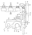
- FIG. 1 is a schematic longitudinal sectional view of a portable printer 1 having a paper cutting device 15 according to a first embodiment of the present invention.
- FIG. 6 is a cross-sectional view of the main part of the opening push button 30 (paper cutting device 15).
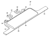
- 3 is a perspective view of the release push button 30.
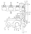
- FIG. It is principal part sectional drawing of the push button 30 for release (paper cutting device 50) part in the paper cutting device 50 by 2nd Example of this invention.
- the release push button is made to face the printing paper issuing port, and the release push button and the manual cutter are integrated. It was realized.
- FIG. 1 is a schematic longitudinal sectional view of the above-described printer, for example, a portable printer 1.
- the portable printer 1 is configured as a thermal printer, and includes a printer housing 2, an opening / closing cover 3, and a label continuum 4. (Printing paper) supply unit 5, position detection unit 6, printing unit 7, battery storage chamber 9 for charging battery 8, adapter connection terminal 10, input unit 11, display unit 12, and control unit 13. And a power switch 14 and a paper cutting device 15.
- the printer housing 2 has a size that can be carried by an operator.
- the printer housing 2 is provided with a belt hanging portion 16 at the top, and the entire portable printer 1 can be suspended from the shoulder of the operator by a shoulder belt 17. Yes.
- it can also be set as the structure which can be mounted
- the opening / closing cover 3 is provided so as to be openable / closable around a cover shaft 18 positioned at a lower corner in FIG. 1, and the label continuous body 4 is stored in the supply unit 5 and the portable printer 1. Can be loaded. *
- the label continuous body 4 has a configuration in which a plurality of label pieces 20 are temporarily attached on a strip-shaped mount 19.
- the label piece 20 is a so-called thermal label, and a surface is coated with a thermosensitive coloring layer so that printing is possible.
- the supply unit 5 winds the label continuum 4 in a roll shape and stores it in the roll, and can feed it out in the direction of the position detection unit 6 and the printing unit 7 in a strip shape. It should be noted that the position detection marks 21 are printed in advance at a predetermined pitch on the back side of the mount 19. *
- the position detection unit 6 includes a position detection sensor 22 attached to the opening / closing cover 3 side, detects a position detection mark 21 located on the back side of the label continuous body 4, and detects the label continuous body 4 (label) for the printing unit 7. The relative position of the piece 20) can be detected.
- the printing unit 7 includes a thermal head 23 (printing head) attached to the printer housing 2 side, a platen roller 24 attached to the opening / closing cover 3 side, and a head biasing spring 25 that biases the thermal head 23 toward the platen roller 24. And a drive motor 26.
- a platen roller gear 28 is provided at one end of the platen roller shaft 27 of the platen roller 24, and a connection gear 29 for transmitting the rotation of the drive motor 26 is provided.
- the label continuum 4 is sandwiched between the thermal head 23 and the platen roller 24, the platen roller 24 is rotated by the drive motor 26, and the thermal is generated according to the print data supplied from the control unit 13 to the thermal head 23.
- a heating element (not shown) of the head 23 is heated to perform thermal printing on the label continuum 4 (label piece 20).
- the printer housing 2 is provided with an opening push button 30 and is operated so as to push the opening push button 30 inward of the printer housing 2, thereby resisting the urging force of the head urging spring 25. 1 is rotated counterclockwise in FIG. 1 around the head shaft 31 to separate the platen roller 24 from the thermal head 23, and the label continuous body 4 can be inserted and loaded between the thermal head 23 and the platen roller 24. To do. As described above, the platen roller 24 and the position detection sensor 22 are attached to the opening / closing cover 3, and the opening / closing cover 3 is separated from the thermal head 23 as the opening / closing of the opening / closing cover 3 from the printer housing 2 is rotated. *
- the rechargeable battery 8 can be removed from and stored in the battery storage chamber 9, and supplies power to the entire portable printer 1 as well as the printing unit 7 (the thermal head 23 and the drive motor 26). *
- the adapter connection terminal 10 is provided in the printer housing 2 and is connected to an external power source (not shown) to connect an AC adapter 32 for charging the charging battery 8. *
- the input unit 11 can input data or commands necessary for the portable printer 1.
- the display unit 12 can display information input by the input unit 11 and other necessary information. *
- the control unit 13 is provided on an electronic board or the like, and is between the position detection unit 6, the printing unit 7, the charging battery 8, the adapter connection terminal 10, the input unit 11, the display unit 12, and the power switch 14 described above. Data and commands are exchanged and these are controlled appropriately. *
- the input unit 11, the display unit 12, the power switch 14, the paper cutting device 15 (particularly located on the surface side of the printer housing 2)
- the area surface on which the opening push button 30), the opening / closing cover 3 and the like are disposed is recessed from the other area surface of the printer housing 2 (in the illustrated example, the edge of the printer housing 2), and the other area.
- a cushion material 33 made of an elastomer or other shock absorbing material is provided on the surface.
- the cushion material 33 is similarly provided on the other ridges of the rectangular parallelepiped printer housing 2 to ensure the impact resistance of the entire portable printer 1.
- the paper cutting device 15 is provided with the above-described opening push button 30.
- 2 is a cross-sectional view of the main part of the opening push button 30 (paper cutting device 15)
- FIG. 3 is a perspective view of the opening push button 30.
- the opening push button 30 is A button main body 34, a waterproof adhesion surface 35 formed on the entire periphery of the peripheral edge of the button main body 34, a button shaft 36 formed integrally with the button main body 34, and a button urging spring 37 as an elastic body;
- a push-out protrusion 38 (FIG. 2) formed to protrude from the back side of the button main body 34 and a paper cutting end 39 formed at the lower end of the waterproof adhesion surface 35.
- FIG. 2 is a cross-sectional view of the main part of the opening push button 30 (paper cutting device 15)
- FIG. 3 is a perspective view of the opening push button 30.
- the opening push button 30 is A button main body 34, a waterproof adhesion surface 35 formed on the entire
- the button main body 34 is a portion exposed to the surface side of the printer housing 2, and an operator who uses the portable printer 1 can move the inside of the printer housing 2 (from the right side in FIG. 2). It is the part pushed in toward the left. *
- the waterproof contact surface 35 can be formed in a state of being recessed toward the inner side of the printer housing 2 relative to the button body 34 to enter the inside of the printer housing 2, and the inner wall surface 2 ⁇ / b> A of the printer housing 2. This is a planar area that can be closely attached to the surface. However, as shown in FIG. 3 in particular, the waterproof contact surface 35 extends longer like a ridge along the length direction of the thermal head 23 (the width direction of the label continuous body 4).
- the heating element 23A (FIG. 2) can be covered entirely, and the sheet cutting end 39, which is the lower end of the heating element 23A, can cut the continuous label body 4 along the width direction. *
- the pair of left and right button shafts 36 are pivotally attached to an internal bracket (not shown) of the printer housing 2, and the entire push button 30 for opening can be rotated by pushing the button body 34.
- the pair of left and right button urging springs 37 meander in the same plane as the waterproof contact surface 35 and form it at the end of the release push button 30, and the part beyond the button shaft 36 from the button body 34.
- the abutting shaft portion 40 is erected at each end portion located in the position. In particular, as shown in FIG. 2, the respective abutting shaft portions 40 abut against the inner wall surface 2 ⁇ / b> A of the printer housing 2, and the pair of left and right button urging springs 37 bend to exhibit their urging force and open.
- the waterproof adhesion surface 35 of the push button 30 can be adhered to the inner wall surface 2 ⁇ / b> A of the printer housing 2.
- the button shaft 36 of the release push button 30 is located between the button urging spring 37 and the waterproof contact surface 35, and the waterproof contact surface 35 is the inner wall surface of the printer housing 2.
- the button urging spring 37 can urge the release push button 30 so as to be in close contact with 2A.
- FIG. 2 (1), (2), and (3) are plan explanatory views schematically showing the button main body 34 and the button urging spring 37 of the release push button 30.
- FIG. 2A is an explanatory diagram when the abutting shaft portion 40 of the button urging spring 37 abuts against the inner wall surface 2A of the printer housing 2, and the urging force by the button urging spring 37 will be described later.
- the button urging spring 37 is not formed with the abutting shaft portion 40, and the spring tip portion 37 A (the portion indicated by hatching in the drawing) is brought into contact with the inner wall surface 2 A of the printer housing 2.
- the biasing force by the button biasing spring 37 is larger than the case of FIG. 2 (2) and FIG. 2 (3). That is, by selecting the urging posture or the contact area of the button urging spring 37 with respect to the inner wall surface 2A of the printer housing 2, the necessary urging force can be applied according to the degree of the waterproof function required for the waterproof contact surface 35. It can be designed as appropriate.
- a cover lock 41 holding the thermal head 23 is rotated around the head shaft 31 on the back side of the release push button 30 (inner side of the printer housing 2). It is provided as possible.
- the cover lock 41 is provided with an abutting inclined plate 42 integrally formed at a portion facing the push-in protrusion 38 at the center of the upper edge portion, and has a cross section on the opposite side through the thermal head 23.
- a pair of left and right platen roller lock engaging portions 43 having a semicircular arc shape are formed.
- the pair of left and right lock pins 44 (FIG. 1) of the platen roller 24 can be engaged with and disengaged from the platen roller lock engagement portion 43. With the lock pin 44 engaged with the platen roller lock engaging portion 43, the platen roller 24 can be brought into contact with the thermal head 23 with a predetermined pressing force (printing pressure), and the label continuous body 4 sandwiched therebetween can Printing is possible.
- a predetermined pressing force printing pressure
- the pushing protrusion 38 located on the back side of the button main body 34 faces the contact inclined plate 42 of the cover lock 41, and is used for opening around the button shaft 36 against the urging force of the button urging spring 37.
- the pushing protrusion 38 presses the contact inclined plate 42, and the cover locks around the head shaft 31 against the urging force of the head urging spring 25.
- 41 is rotated together with the thermal head 23 in the counterclockwise direction in FIG. Accordingly, the lock pin 44 of the platen roller 24 is released from the platen roller lock engaging portion 43 of the cover lock 41, the thermal head 23 and the platen roller 24 are separated from each other, and the label continuous body 4 can be loaded therebetween. Become. *
- a tapered surface 45 is formed at the upper end portion of the platen roller lock engaging portion 43, and after the lock pin 44 of the platen roller 24 contacts the tapered surface 45 during the closing operation of the opening / closing cover 3, It is easy to engage with the roller lock engaging portion 43.
- the sheet cutting end 39 is formed from the lower end of the waterproof adhesion surface 35 of the release push button 30, and is formed between the thermal head 23 and the platen roller 24.
- the sheet cutting end 39 is opposed to the label continuum 4 that has been transferred to the issuing port 46, so that the label continuum 4 (mounting sheet 19 and label piece 20) can be cut at a predetermined location.
- a material for the release push button 30 paper cutting end 39
- a synthetic resin material having a predetermined rigidity and elasticity is generally adopted according to the type of the label continuous body 4 and other printing paper. can do.
- the portable printer 1 can carry the thermal head 23 so that the thermal head 23 is positioned above the platen roller 24, and in particular, as shown in FIG.
- the lower end portion (sheet cutting end portion 39) of the button 30 is located on the outer side of the opening / closing cover 3. That is, the paper cutting end 39 is positioned slightly outward (distance D shown in FIG. 2) from the outer surface of the front end portion of the opening / closing cover 3, so that it can be pressed in the rain or other times. Even if the water droplet W reaches the paper cutting end 39 through the button 30, it simply hangs down on the ground without touching the opening / closing cover 3 from the paper cutting end 39 protruding like a bag. The risk of intrusion is reduced. Further, since the label continuum 4 printed and issued to the issuing port 46 faces the paper cutting end 39 on the outer side of the issuing port 46, the label continuous body 4 in the portion of the paper cutting end 39 is provided. Cutting operation can be performed easily and reliably. *
- the push-out protrusion 38 is pushed into the inside of the printer housing 2 against the urging force of the button urging spring 37 (FIG. 2), so that the push-out protrusion 38 is covered with a cover lock.
- the abutting inclined plate 42 is rotated counterclockwise in FIG. 2 around the head shaft 31 against the urging force of the head urging spring 25, and the platen roller lock engaging portion 43, the lock pin 44, And the platen roller 24 together with the opening / closing cover 3 is released from the thermal head 23.
- the push button 30 for opening in the paper cutting device 15 has the button body 34 exposed to the outside, and the opening operation itself is secured. Since the waterproof contact surface 35 is in close contact with the inner wall surface 2A of the printer housing 2 with a predetermined pressing force by the biasing force of the biasing spring 37, it is possible to prevent water from entering from this portion. That is, since the part of the release push button 30 is adjacent to the part of the printing unit 7 reaching the thermal head 23 and further to the control unit 13, by performing the waterproof function described above, the printing unit 7 and the control unit 13 are provided. It is possible to reduce the frequency of failures and ensure the stability of operation even when the portable printer 1 is used outdoors. *
- the lower end of the push button 30 for opening facing the issuing port 46 of the label continuous body 4 is used as the paper cutting end 39. If the operation is performed so that the predetermined portion of the finished label continuous body 4 is torn off in a state where the predetermined portion is applied to the paper cutting end portion 39, the label continuous body 4 can be easily cut manually.
- the opening push button 30 is operated to open the opening / closing cover 3, the position of the sheet cutting end 39, which is the lower end of the opening push button 30, is shifted from a predetermined portion. Since the release push button 30 is not operated during the cutting operation of the body 4, the cutting operation itself is not hindered. *
- the paper cutting end 39 is integrally formed with the opening push button 30 for opening the opening / closing cover 3 and the platen roller 24, the number of parts is reduced, and the entire portable printer 1 is reduced in size and weight. Can contribute.
- the paper cutting device according to the present invention can also be adopted in a desktop printer or other printers. *
- FIG. 4 is a cross-sectional view of the main part of the opening push button 30 (paper cutting device 50) portion in the paper cutting device 50 according to the second embodiment of the present invention.
- the metal plate 51 is attached to the inner side edge portion of the paper cutting end portion 39 of the opening push button 30 as described above. Therefore, in this paper cutting device 50, the lower end portion of the metal plate 51 functions as a paper cutting end portion 52 for manually cutting the label continuous body 4 instead of the paper cutting end portion 39. become.
- the material of the metal plate 51 is arbitrary, but a general stainless steel material or the like can be adopted. *
- FIG. 2 is a schematic plan view illustrating the biasing posture of the button biasing spring 37 against the inner wall surface 2A of the printer housing 2 in the same manner as described with reference to FIGS. 2 (1), (2), and (3).
- the contact area it is possible to appropriately design the required urging force according to the degree of the waterproof function required for the waterproof contact surface 35.
- the paper cutting end 52 of the metal plate 51 faces the issuing port 46 through which the printed label continuous body 4 is transferred. Can be more easily performed, and can be mounted on the portable printer 1 (FIG. 1) as described above to reduce the number of parts, thereby contributing to a reduction in size and weight.
- SYMBOLS 1 Portable printer (printer, FIG. 1) 2 Printer housing 2A Inner wall surface of printer housing 2 (FIG. 2) 3 Opening and closing cover 4 Label continuous body (printing paper) 5 Supply part 6 Position detection part 7 Printing part 8 Charging battery 9 Battery Storage chamber 10 Adapter connection terminal 11 for connecting the AC adapter 32 Input section 12 Display section 13 Control section 14 Power switch 15 Paper cutting device of the portable printer 1 (first embodiment, FIG. 2) 16 Belt hook section 17 Shoulder belt 18 Cover shaft 19 of the open / close cover 3 Mount 20 of the label continuum 4 Label piece 21 Position detection mark 22 Position detection sensor 23 Thermal head (printing head) 23A Heating element of the thermal head 23 (printing head) FIG.
Abstract
[Problem] To provide a printer paper-cutting device that is lightweight and can be easily operated, and doubles as a release push button (30) for releasing an access cover (3), and a manual cutter for cutting printing paper (a continuous label strip (4)), thereby reducing the number of components. [Solution] This printer paper-cutting device integrates a release push button (30) and a manual cutter, and has: a platen roller (24) that sandwiches and rotates printing paper (4) between the platen roller and a printing head (23) (a thermal head (23)); and a release push button (30) that operates in such a manner as to separate the platen roller (24) and the print head (23) from each other. The printer paper-cutting device is characterized in that the release push button (30) is made to face a discharge opening (46) for the printing paper (4) printed by the print head (24), and the lower side tip of the release push button (30) is formed as a paper-cutting end (39).
Description
本発明はプリンターの用紙切断装置にかかるもので、とくに部品点数を削減したプリンターの用紙切断装置に関するものである。
The present invention relates to a paper cutting device for a printer, and more particularly to a paper cutting device for a printer with a reduced number of parts.
従来から、卓上型プリンターや携帯式プリンターなど各種のプリンターに帯状のラベル連続体その他の印字用紙を装填するために、開閉カバーなどを開放して、そのプリンターハウジング内に印字用紙を収納する必要がある。 この開閉カバーなどの開放のために操作する開放用押しボタンを設けたプリンターが提案されている。
Conventionally, in order to load a continuous strip of label or other printing paper into various printers such as desktop printers and portable printers, it has been necessary to open the opening / closing cover and store the printing paper in the printer housing. is there. A printer with a push button for opening to open the opening / closing cover has been proposed. *
一方、印字発行された印字用紙を手動により所定の長さに切断することが必要であり、この切断のための、いわゆるマニュアルカッターを備えておくことも必要である。
On the other hand, it is necessary to manually cut the printed paper to a predetermined length, and it is necessary to provide a so-called manual cutter for this cutting. *
しかしながら、プリンターとして、開閉カバーの開放用押しボタンとマニュアルカッターとを別々に設けることは、装置の複雑化および大型化を招くという問題があり、とくに携帯式プリンターは、小型軽量で簡易に扱えることが望ましく、極力部品点数を少なく、かつ構造を簡略化しなければならないという問題がある。
However, as a printer, separately providing the push button for opening the opening / closing cover and the manual cutter has the problem that the device becomes complicated and large, and in particular, portable printers are small, light and easy to handle. However, there is a problem that the number of parts should be as small as possible and the structure should be simplified.
本発明は以上のような諸問題にかんがみなされたもので、部品点数を少なくし、装置を複雑化することなく、小型軽量で簡易に操作することができるプリンターの用紙切断装置を提供することを課題とする。
The present invention has been considered in view of the above problems, and it is an object of the present invention to provide a paper cutting device for a printer that can be easily operated with a small size and light weight without reducing the number of components and complicating the device. Let it be an issue. *
また本発明は、開放用押しボタンおよびマニュアルカッターの構成を簡略化したプリンターの用紙切断装置を提供することを課題とする。
It is another object of the present invention to provide a paper cutting device for a printer in which the configuration of the opening push button and the manual cutter is simplified. *
また本発明は、開閉カバーを開放するための開放用押しボタン、および印字用紙の切断用のマニュアルカッターを兼用可能としたプリンターの用紙切断装置を提供することを課題とする。
Another object of the present invention is to provide a paper cutting device for a printer that can be used both as a push button for opening an opening / closing cover and a manual cutter for cutting printing paper.
すなわち本発明は、開放用押しボタンおよびマニュアルカッターを一体化することに着目したもので、プリンターハウジングと、このプリンターハウジングに装填される印字用紙に印字可能な印字ヘッドと、この印字ヘッドとの間に上記印字用紙を挟持して回転することにより上記印字用紙を移送可能なプラテンローラーと、このプラテンローラーおよび上記印字ヘッドを互いに離反させるように操作する開放用押しボタンと、を有するプリンターの用紙切断装置であって、上記開放用押しボタンを上記印字ヘッドによる印字済みの上記印字用紙の発行口に臨ませるとともに、上記開放用押しボタンの下方側先端部を用紙切断用端部として形成していることを特徴とするプリンターの用紙切断装置である。
That is, the present invention focuses on the integration of the release push button and the manual cutter, and includes a printer housing, a print head capable of printing on print paper loaded in the printer housing, and the print head. Paper cutting of a printer having a platen roller capable of transporting the printing paper by sandwiching and rotating the printing paper and an opening push button for operating the platen roller and the printing head to move away from each other In the apparatus, the push button for opening is made to face an issue port of the printing paper printed by the print head, and a lower end portion of the push button for opening is formed as a paper cutting end portion. This is a paper cutting device for a printer. *
上記開放用押しボタンの上記用紙切断用端部は、上記印字ヘッドおよび上記プラテンローラーとの間から上記発行口に発行されてくる上記印字用紙に対向可能であることができる。
The paper cutting end of the opening push button can be opposed to the print paper issued to the issuing port from between the print head and the platen roller. *
上記印字ヘッドを上記プラテンローラーに押し付けるヘッド付勢スプリングを設け、このヘッド付勢スプリングの付勢力に抗して上記開放用押しボタンを上記プリンターハウジングに対して操作することにより、上記印字ヘッドおよび上記プラテンローラーを互いに離反可能としていることができる。
A head biasing spring that presses the print head against the platen roller is provided, and the release push button is operated with respect to the printer housing against the biasing force of the head biasing spring. The platen rollers can be separated from each other. *
上記印字ヘッドは、これを上記プリンターハウジングに取り付けるとともに、上記プラテンローラーは、上記プリンターハウジングに開閉可能に設けた開閉カバーにこれを回転可能に取り付け、上記開放用押しボタンの操作によりこの開閉カバーを上記プリンターハウジングに対して開放して上記印字ヘッドから上記プラテンローラーを離反させることができる。
The print head is attached to the printer housing, and the platen roller is rotatably attached to an open / close cover provided in the printer housing so as to be openable / closable. The open / close cover is attached by operating the release push button. The platen roller can be separated from the print head by opening the printer housing. *
上記用紙切断用端部に、金属プレートを取り付けていることができる。
A metal plate can be attached to the paper cutting end.
本発明によるプリンターの用紙切断装置においては、開放用押しボタンを印字ヘッドによる印字済みの印字用紙の発行口に臨ませるとともに、開放用押しボタンの下方側先端部を用紙切断端部として形成しているので、開放用押しボタンおよびマニュアルカッターを一体化し、部品点数を削減し、プリンターとくに携帯式プリンターの小型軽量化を実現することができる。
In the paper cutting device of the printer according to the present invention, the release push button is made to face the print paper issuing port printed by the print head, and the lower end of the release push button is formed as the paper cut end. Therefore, the push button for opening and the manual cutter can be integrated, the number of parts can be reduced, and the printer, especially the portable printer, can be reduced in size and weight.
本発明は、開放用押しボタンを印字用紙の発行口に臨ませるとともに、開放用押しボタンおよびマニュアルカッターを一体化したので、構成を簡略化し、小型軽量とすることができるプリンターの用紙切断装置を実現した。
According to the present invention, the release push button is made to face the printing paper issuing port, and the release push button and the manual cutter are integrated. It was realized.
つぎに本発明の第1の実施例によるプリンターの用紙切断装置を図1ないし図3にもとづき説明する。 図1は、上記プリンターたとえば携帯式プリンター1の概略縦断面図であって、携帯式プリンター1は、サーマルプリンターとしてこれを構成してあり、プリンターハウジング2と、開閉カバー3と、ラベル連続体4(印字用紙)の供給部5と、位置検出部6と、印字部7と、充電バッテリー8のバッテリー収納室9と、アダプター接続端子10と、入力部11と、表示部12と、制御部13と、電源スイッチ14と、用紙切断装置15と、を有する。
Next, a paper cutting device for a printer according to a first embodiment of the present invention will be described with reference to FIGS. FIG. 1 is a schematic longitudinal sectional view of the above-described printer, for example, a portable printer 1. The portable printer 1 is configured as a thermal printer, and includes a printer housing 2, an opening / closing cover 3, and a label continuum 4. (Printing paper) supply unit 5, position detection unit 6, printing unit 7, battery storage chamber 9 for charging battery 8, adapter connection terminal 10, input unit 11, display unit 12, and control unit 13. And a power switch 14 and a paper cutting device 15. *
プリンターハウジング2は、作業者が携帯可能な大きさを有し、図1中、上方にベルト掛け部16を設けて、肩掛けベルト17により携帯式プリンター1全体を作業者の肩から吊り下げ可能としている。もちろん、作業者の腰に装着可能とする構成とすることもできる。 さらにプリンターハウジング2には、図1中、下方隅部に位置したカバー軸18のまわりに上記開閉カバー3を開閉可能に設けて、供給部5へのラベル連続体4の収納および携帯式プリンター1への装填を可能としている。
The printer housing 2 has a size that can be carried by an operator. In FIG. 1, the printer housing 2 is provided with a belt hanging portion 16 at the top, and the entire portable printer 1 can be suspended from the shoulder of the operator by a shoulder belt 17. Yes. Of course, it can also be set as the structure which can be mounted | worn to a worker's waist | hip | lumbar. Further, in the printer housing 2, the opening / closing cover 3 is provided so as to be openable / closable around a cover shaft 18 positioned at a lower corner in FIG. 1, and the label continuous body 4 is stored in the supply unit 5 and the portable printer 1. Can be loaded. *
ラベル連続体4は、帯状の台紙19上に複数枚のラベル片20を仮着した構成である。ラベル片20は、いわゆるサーマルラベルであって、その表面に感熱発色層を塗工して、印字可能としてある。 供給部5は、ラベル連続体4をロール状に巻いてその内部に収納し、位置検出部6および印字部7方向に帯状に繰り出し可能としている。 なお、台紙19の裏面側には、所定ピッチで位置検出用マーク21をあらかじめ印刷してある。
The label continuous body 4 has a configuration in which a plurality of label pieces 20 are temporarily attached on a strip-shaped mount 19. The label piece 20 is a so-called thermal label, and a surface is coated with a thermosensitive coloring layer so that printing is possible. The supply unit 5 winds the label continuum 4 in a roll shape and stores it in the roll, and can feed it out in the direction of the position detection unit 6 and the printing unit 7 in a strip shape. It should be noted that the position detection marks 21 are printed in advance at a predetermined pitch on the back side of the mount 19. *
位置検出部6は、開閉カバー3側に取り付けた位置検出センサー22を有し、ラベル連続体4の裏面側に位置する位置検出用マーク21を検出して印字部7に対するラベル連続体4(ラベル片20)の相対位置を検出可能とする。
The position detection unit 6 includes a position detection sensor 22 attached to the opening / closing cover 3 side, detects a position detection mark 21 located on the back side of the label continuous body 4, and detects the label continuous body 4 (label) for the printing unit 7. The relative position of the piece 20) can be detected. *
印字部7は、プリンターハウジング2側に取り付けたサーマルヘッド23(印字ヘッド)と、開閉カバー3側に取り付けたプラテンローラー24と、サーマルヘッド23をプラテンローラー24方向に付勢するヘッド付勢スプリング25と、駆動モーター26と、を有する。 プラテンローラー24のプラテンローラー軸27の一方側端部にはプラテンローラーギア28を設けるとともに、駆動モーター26の回転を伝達するための連結ギア29を設け、開閉カバー3のプリンターハウジング2への閉鎖により、プラテンローラーギア28と連結ギア29とを係合させて、駆動モーター26によりプラテンローラー24を回転駆動可能としている。
The printing unit 7 includes a thermal head 23 (printing head) attached to the printer housing 2 side, a platen roller 24 attached to the opening / closing cover 3 side, and a head biasing spring 25 that biases the thermal head 23 toward the platen roller 24. And a drive motor 26. A platen roller gear 28 is provided at one end of the platen roller shaft 27 of the platen roller 24, and a connection gear 29 for transmitting the rotation of the drive motor 26 is provided. By closing the open / close cover 3 to the printer housing 2, The platen roller gear 28 and the connecting gear 29 are engaged, and the platen roller 24 can be rotationally driven by the drive motor 26. *
すなわち、サーマルヘッド23およびプラテンローラー24の間にラベル連続体4を挟持して、駆動モーター26によりプラテンローラー24を回転駆動するとともに、制御部13からサーマルヘッド23に供給した印字データに応じてサーマルヘッド23の発熱素子(図示せず)を発熱させ、ラベル連続体4(ラベル片20)にサーマル印字を行う。
That is, the label continuum 4 is sandwiched between the thermal head 23 and the platen roller 24, the platen roller 24 is rotated by the drive motor 26, and the thermal is generated according to the print data supplied from the control unit 13 to the thermal head 23. A heating element (not shown) of the head 23 is heated to perform thermal printing on the label continuum 4 (label piece 20). *
プリンターハウジング2には開放用押しボタン30を設け、開放用押しボタン30をプリンターハウジング2の内方に押し込むように操作することにより、ヘッド付勢スプリング25の付勢力に抗して、サーマルヘッド23をそのヘッド軸31のまわりに図1中、反時計方向に回動させてプラテンローラー24をサーマルヘッド23から離反させ、サーマルヘッド23およびプラテンローラー24の間にラベル連続体4を挿通装填可能とする。 既述のように、開閉カバー3にはプラテンローラー24および位置検出センサー22を取り付けてあり、開閉カバー3のプリンターハウジング2からの開放回動にともなってサーマルヘッド23から離反する。
The printer housing 2 is provided with an opening push button 30 and is operated so as to push the opening push button 30 inward of the printer housing 2, thereby resisting the urging force of the head urging spring 25. 1 is rotated counterclockwise in FIG. 1 around the head shaft 31 to separate the platen roller 24 from the thermal head 23, and the label continuous body 4 can be inserted and loaded between the thermal head 23 and the platen roller 24. To do. As described above, the platen roller 24 and the position detection sensor 22 are attached to the opening / closing cover 3, and the opening / closing cover 3 is separated from the thermal head 23 as the opening / closing of the opening / closing cover 3 from the printer housing 2 is rotated. *
充電バッテリー8は、バッテリー収納室9に収脱可能であって、上述の印字部7(サーマルヘッド23および駆動モーター26など)はもちろん、携帯式プリンター1全体に電力を供給する。
The rechargeable battery 8 can be removed from and stored in the battery storage chamber 9, and supplies power to the entire portable printer 1 as well as the printing unit 7 (the thermal head 23 and the drive motor 26). *
アダプター接続端子10は、プリンターハウジング2にこれを設け、外部電源(図示せず)に接続して充電バッテリー8に充電するためのACアダプター32を接続する。
The adapter connection terminal 10 is provided in the printer housing 2 and is connected to an external power source (not shown) to connect an AC adapter 32 for charging the charging battery 8. *
入力部11は、携帯式プリンター1に必要なデータないしコマンドを入力可能とする。 表示部12は、入力部11により入力された情報およびその他必要な情報を表示可能とする。
The input unit 11 can input data or commands necessary for the portable printer 1. The display unit 12 can display information input by the input unit 11 and other necessary information. *
制御部13は、電子基板などにこれを設けてあり、上述の位置検出部6、印字部7、充電バッテリー8、アダプター接続端子10、入力部11、表示部12および電源スイッチ14との間でデータおよびコマンドの授受を行うとともに、これらを適宜制御する。
The control unit 13 is provided on an electronic board or the like, and is between the position detection unit 6, the printing unit 7, the charging battery 8, the adapter connection terminal 10, the input unit 11, the display unit 12, and the power switch 14 described above. Data and commands are exchanged and these are controlled appropriately. *
なお、携帯式プリンター1においては、落下などによる衝撃に対する耐性を確保するために、とくにプリンターハウジング2の表面側に位置している入力部11、表示部12、電源スイッチ14、用紙切断装置15(開放用押しボタン30)、開閉カバー3などを配置している領域面をプリンターハウジング2の他の領域面(図示の例では、プリンターハウジング2の稜縁部)から凹ませるとともに、当該他の領域面にエラストマーその他の衝撃吸収性材料によるクッション材33を設けている。 また、直方体形状のプリンターハウジング2における他の稜縁部にも同様に、クッション材33を設けて携帯式プリンター1全体の耐衝撃性を確保している。
In the portable printer 1, in order to ensure resistance to impact caused by dropping or the like, the input unit 11, the display unit 12, the power switch 14, the paper cutting device 15 (particularly located on the surface side of the printer housing 2) The area surface on which the opening push button 30), the opening / closing cover 3 and the like are disposed is recessed from the other area surface of the printer housing 2 (in the illustrated example, the edge of the printer housing 2), and the other area. A cushion material 33 made of an elastomer or other shock absorbing material is provided on the surface. In addition, the cushion material 33 is similarly provided on the other ridges of the rectangular parallelepiped printer housing 2 to ensure the impact resistance of the entire portable printer 1. *
本実施例にかかる用紙切断装置15は、上述した開放用押しボタン30の部分にこれを設けている。 図2は、開放用押しボタン30(用紙切断装置15)部分の要部断面図、図3は、開放用押しボタン30の斜視図であり、用紙切断装置15において、開放用押しボタン30は、ボタン本体34と、ボタン本体34の周縁部の全周をめぐってこれに形成した防水用密着面35と、ボタン本体34に一体に形成したそのボタン軸36および弾性体としてのボタン付勢スプリング37と、ボタン本体34の裏面側に突出して形成した押込み用突出部38(図2)と、防水用密着面35の下方側先端部に形成した用紙切断用端部39と、を有する。
The paper cutting device 15 according to the present embodiment is provided with the above-described opening push button 30. 2 is a cross-sectional view of the main part of the opening push button 30 (paper cutting device 15), and FIG. 3 is a perspective view of the opening push button 30. In the paper cutting device 15, the opening push button 30 is A button main body 34, a waterproof adhesion surface 35 formed on the entire periphery of the peripheral edge of the button main body 34, a button shaft 36 formed integrally with the button main body 34, and a button urging spring 37 as an elastic body; A push-out protrusion 38 (FIG. 2) formed to protrude from the back side of the button main body 34 and a paper cutting end 39 formed at the lower end of the waterproof adhesion surface 35. *
ボタン本体34は、図1に示したようにプリンターハウジング2の表面側に露出する部分であって、携帯式プリンター1を使用する作業者がプリンターハウジング2の内方(図2中、右方から左方)に向かって押し込む部分である。
As shown in FIG. 1, the button main body 34 is a portion exposed to the surface side of the printer housing 2, and an operator who uses the portable printer 1 can move the inside of the printer housing 2 (from the right side in FIG. 2). It is the part pushed in toward the left. *
防水用密着面35は、ボタン本体34より相対的にプリンターハウジング2の内方側に凹んだ状態でこれを形成してプリンターハウジング2の内側に入り込むことができるとともに、プリンターハウジング2の内壁面2Aに密着可能な平面領域である。 ただし、防水用密着面35は、とくに図3に示すように、サーマルヘッド23の長さ方向(ラベル連続体4の幅方向)に沿ってより長く庇のように延びており、サーマルヘッド23の発熱素子23A(図2)のすべてを覆うことができるようにしているとともに、その下方側先端部である用紙切断用端部39がラベル連続体4を幅方向に沿って切断可能である。
The waterproof contact surface 35 can be formed in a state of being recessed toward the inner side of the printer housing 2 relative to the button body 34 to enter the inside of the printer housing 2, and the inner wall surface 2 </ b> A of the printer housing 2. This is a planar area that can be closely attached to the surface. However, as shown in FIG. 3 in particular, the waterproof contact surface 35 extends longer like a ridge along the length direction of the thermal head 23 (the width direction of the label continuous body 4). The heating element 23A (FIG. 2) can be covered entirely, and the sheet cutting end 39, which is the lower end of the heating element 23A, can cut the continuous label body 4 along the width direction. *
左右一対のボタン軸36は、プリンターハウジング2の内部ブラケット(図示せず)にこれを軸着し、ボタン本体34の押込み操作により、開放用押しボタン30全体を回動可能としている。
The pair of left and right button shafts 36 are pivotally attached to an internal bracket (not shown) of the printer housing 2, and the entire push button 30 for opening can be rotated by pushing the button body 34. *
左右一対のボタン付勢スプリング37は、防水用密着面35と同一平面内で蛇行させて開放用押しボタン30の端部にこれを形成しており、ボタン本体34からボタン軸36をこえた部位に位置するそれぞれの端部に当接軸部40を起立させている。 とくに図2に示すように、それぞれの当接軸部40がプリンターハウジング2の内壁面2Aに当接して、左右一対のボタン付勢スプリング37が撓むことにより、その付勢力を発揮して開放用押しボタン30の防水用密着面35をプリンターハウジング2の内壁面2Aに密着可能とする。 換言すれば、開放用押しボタン30のボタン軸36は、ボタン付勢スプリング37と防水用密着面35との間に位置してこれを設けて、防水用密着面35がプリンターハウジング2の内壁面2Aに密着させるように、ボタン付勢スプリング37が開放用押しボタン30を付勢可能としている。 なおボタン付勢スプリング37を蛇行して形成することにより、所定の付勢力を得るための必要な長さを狭い空間内で得ることが可能となり、かつ、ボタン本体34と一体形成することにより、とくに小型軽量に製造する必要があるこの種携帯式プリンター1に有利である。
The pair of left and right button urging springs 37 meander in the same plane as the waterproof contact surface 35 and form it at the end of the release push button 30, and the part beyond the button shaft 36 from the button body 34. The abutting shaft portion 40 is erected at each end portion located in the position. In particular, as shown in FIG. 2, the respective abutting shaft portions 40 abut against the inner wall surface 2 </ b> A of the printer housing 2, and the pair of left and right button urging springs 37 bend to exhibit their urging force and open. The waterproof adhesion surface 35 of the push button 30 can be adhered to the inner wall surface 2 </ b> A of the printer housing 2. In other words, the button shaft 36 of the release push button 30 is located between the button urging spring 37 and the waterproof contact surface 35, and the waterproof contact surface 35 is the inner wall surface of the printer housing 2. The button urging spring 37 can urge the release push button 30 so as to be in close contact with 2A. By forming the button urging spring 37 in a meandering manner, it becomes possible to obtain a necessary length for obtaining a predetermined urging force in a narrow space, and by integrally forming with the button body 34, This is particularly advantageous for this type of portable printer 1 that needs to be manufactured in a small and lightweight manner. *
図2(1)、(2)、(3)は、開放用押しボタン30のボタン本体34およびボタン付勢スプリング37を模式的に描いた平面説明図である。ただし、ボタン付勢スプリング37の可撓性は、それぞれ同程度とする。 図2(1)は、ボタン付勢スプリング37の当接軸部40がプリンターハウジング2の内壁面2Aに当接する場合の説明図であって、ボタン付勢スプリング37による付勢力は、後述する図2(2)および図2(3)の場合よりも小さい。 図2(2)は、ボタン付勢スプリング37に当接軸部40を形成せずに、そのスプリング先端部分37A(図中、ハッチングで示している部分)がプリンターハウジング2の内壁面2Aに当接する場合(あるいは、ボタン付勢スプリング37に当接軸部40を形成してもプリンターハウジング2の内壁面2Aに係合凹部(図示せず)を形成して、当接軸部40がこの係合凹部に係合する場合)の説明図であって、ボタン付勢スプリング37による付勢力は、中程度である(図2(1)の場合よりも強く、図2(3)の場合よりも弱い)。 図2(3)は、ボタン付勢スプリング37に当接軸部40を形成せずに、ボタン付勢スプリング37全体(図中、ハッチングで示している部分)がプリンターハウジング2の内壁面2Aに当接する場合の説明図であって、ボタン付勢スプリング37による付勢力は、図2(2)および図2(3)の場合よりも大きい。 すなわち、プリンターハウジング2の内壁面2Aに対するボタン付勢スプリング37の付勢態勢ないしは当接領域を選択することにより、防水用密着面35に要請される防水機能の程度に応じて必要な付勢力を適宜設計することができる。
2 (1), (2), and (3) are plan explanatory views schematically showing the button main body 34 and the button urging spring 37 of the release push button 30. FIG. However, the flexibility of the button urging springs 37 is approximately the same. FIG. 2A is an explanatory diagram when the abutting shaft portion 40 of the button urging spring 37 abuts against the inner wall surface 2A of the printer housing 2, and the urging force by the button urging spring 37 will be described later. 2 (2) and smaller than in the case of FIG. 2 (3). In FIG. 2 (2), the button urging spring 37 is not formed with the abutting shaft portion 40, and the spring tip portion 37 A (the portion indicated by hatching in the drawing) is brought into contact with the inner wall surface 2 A of the printer housing 2. In the case of contact (or even if the contact shaft portion 40 is formed on the button urging spring 37, an engagement recess (not shown) is formed on the inner wall surface 2A of the printer housing 2, and the contact shaft portion 40 is connected to this engagement shaft portion 40. It is explanatory drawing of the case where it engages with a joint recessed part, Comprising: The urging | biasing force by the button urging | biasing spring 37 is moderate (stronger than the case of FIG. 2 (1), rather than the case of FIG. 2 (3)) weak). In FIG. 2 (3), the button urging spring 37 is not formed with the contact shaft portion 40, and the entire button urging spring 37 (the portion indicated by hatching in the figure) is attached to the inner wall surface 2 A of the printer housing 2. It is explanatory drawing in the case of contact | abutting, Comprising: The biasing force by the button biasing spring 37 is larger than the case of FIG. 2 (2) and FIG. 2 (3). That is, by selecting the urging posture or the contact area of the button urging spring 37 with respect to the inner wall surface 2A of the printer housing 2, the necessary urging force can be applied according to the degree of the waterproof function required for the waterproof contact surface 35. It can be designed as appropriate. *
とくに図2に示すように、開放用押しボタン30の裏面側(プリンターハウジング2の内方側)には、前記サーマルヘッド23を保持しているカバーロック41を前記ヘッド軸31のまわりに回動可能に設けている。 カバーロック41には、その上縁部中央に位置して、押込み用突出部38に対向する部位に当接傾斜プレート42を一体形成して設けるとともに、サーマルヘッド23を介して反対側に断面ほぼ半円弧状の左右一対のプラテンローラーロック係合部43を形成している。 プラテンローラーロック係合部43にはプラテンローラー24の左右一対のロックピン44(図1)が係脱可能である。ロックピン44がプラテンローラーロック係合部43に係合した状態で、プラテンローラー24がサーマルヘッド23に所定押圧力(印字圧力)で当接可能であり、その間に挟持するラベル連続体4への印字が可能な状態となる。
In particular, as shown in FIG. 2, a cover lock 41 holding the thermal head 23 is rotated around the head shaft 31 on the back side of the release push button 30 (inner side of the printer housing 2). It is provided as possible. The cover lock 41 is provided with an abutting inclined plate 42 integrally formed at a portion facing the push-in protrusion 38 at the center of the upper edge portion, and has a cross section on the opposite side through the thermal head 23. A pair of left and right platen roller lock engaging portions 43 having a semicircular arc shape are formed. The pair of left and right lock pins 44 (FIG. 1) of the platen roller 24 can be engaged with and disengaged from the platen roller lock engagement portion 43. With the lock pin 44 engaged with the platen roller lock engaging portion 43, the platen roller 24 can be brought into contact with the thermal head 23 with a predetermined pressing force (printing pressure), and the label continuous body 4 sandwiched therebetween can Printing is possible. *
ボタン本体34の裏面側に位置する押込み用突出部38は、このカバーロック41の当接傾斜プレート42に対向しており、ボタン付勢スプリング37の付勢力に抗したボタン軸36まわりの開放用押しボタン30の図2中、時計方向の回動により、押込み用突出部38が当接傾斜プレート42を押圧し、さらにヘッド付勢スプリング25の付勢力に抗してヘッド軸31まわりにカバーロック41をサーマルヘッド23とともに図2中、反時計方向に回動させる。 したがって、プラテンローラー24のロックピン44がカバーロック41のプラテンローラーロック係合部43から離脱した状態となり、サーマルヘッド23およびプラテンローラー24とを互いに離反させ、その間にラベル連続体4を装填可能となる。
The pushing protrusion 38 located on the back side of the button main body 34 faces the contact inclined plate 42 of the cover lock 41, and is used for opening around the button shaft 36 against the urging force of the button urging spring 37. As the push button 30 rotates in the clockwise direction in FIG. 2, the pushing protrusion 38 presses the contact inclined plate 42, and the cover locks around the head shaft 31 against the urging force of the head urging spring 25. 41 is rotated together with the thermal head 23 in the counterclockwise direction in FIG. Accordingly, the lock pin 44 of the platen roller 24 is released from the platen roller lock engaging portion 43 of the cover lock 41, the thermal head 23 and the platen roller 24 are separated from each other, and the label continuous body 4 can be loaded therebetween. Become. *
また、プラテンローラーロック係合部43の上方端部には、テーパー面45を形成してあり、開閉カバー3の閉鎖作動時にプラテンローラー24のロックピン44がテーパー面45に当接したのち、プラテンローラーロック係合部43に係合しやすくしている。
Further, a tapered surface 45 is formed at the upper end portion of the platen roller lock engaging portion 43, and after the lock pin 44 of the platen roller 24 contacts the tapered surface 45 during the closing operation of the opening / closing cover 3, It is easy to engage with the roller lock engaging portion 43. *
とくに図2および図3に示すように、用紙切断用端部39は、開放用押しボタン30における防水用密着面35の下方側先端部からこれを形成し、サーマルヘッド23およびプラテンローラー24の間から発行口46に移送されてきたラベル連続体4に用紙切断用端部39が対向し、所定の部位でラベル連続体4(台紙19、ラベル片20)を切断可能である。 なお、開放用押しボタン30(用紙切断用端部39)の材料としては、ラベル連続体4その他の印字用紙の種類に応じて、一般的には所定の剛性および弾性を有する合成樹脂材料を採用することができる。
In particular, as shown in FIGS. 2 and 3, the sheet cutting end 39 is formed from the lower end of the waterproof adhesion surface 35 of the release push button 30, and is formed between the thermal head 23 and the platen roller 24. The sheet cutting end 39 is opposed to the label continuum 4 that has been transferred to the issuing port 46, so that the label continuum 4 (mounting sheet 19 and label piece 20) can be cut at a predetermined location. As a material for the release push button 30 (paper cutting end 39), a synthetic resin material having a predetermined rigidity and elasticity is generally adopted according to the type of the label continuous body 4 and other printing paper. can do. *
さらに、とくに図1に示すように、当該携帯式プリンター1は、サーマルヘッド23がプラテンローラー24より上方に位置するようにこれを携帯可能であるとともに、とくに図2に示すように、開放用押しボタン30の下方側先端部(用紙切断用端部39)は、開閉カバー3より外方側に位置している。 すなわち、用紙切断用端部39が開閉カバー3の先端部の外表面より、わずかに(図2に示す間隔D)分だけ外方側に位置していることにより、雨天その他の時に開放用押しボタン30を伝って水滴Wが用紙切断用端部39に至っても、庇のように出ている用紙切断用端部39から開閉カバー3に触れることなく地上に垂れ落ちるのみであり、プリンターハウジング2内に侵入するおそれは軽減されている。 また、発行口46に印字発行されてくるラベル連続体4は、発行口46の外方側で用紙切断用端部39に対向するので、用紙切断用端部39の部分におけるラベル連続体4の切断操作を容易かつ確実に行うことができる。
Further, particularly as shown in FIG. 1, the portable printer 1 can carry the thermal head 23 so that the thermal head 23 is positioned above the platen roller 24, and in particular, as shown in FIG. The lower end portion (sheet cutting end portion 39) of the button 30 is located on the outer side of the opening / closing cover 3. That is, the paper cutting end 39 is positioned slightly outward (distance D shown in FIG. 2) from the outer surface of the front end portion of the opening / closing cover 3, so that it can be pressed in the rain or other times. Even if the water droplet W reaches the paper cutting end 39 through the button 30, it simply hangs down on the ground without touching the opening / closing cover 3 from the paper cutting end 39 protruding like a bag. The risk of intrusion is reduced. Further, since the label continuum 4 printed and issued to the issuing port 46 faces the paper cutting end 39 on the outer side of the issuing port 46, the label continuous body 4 in the portion of the paper cutting end 39 is provided. Cutting operation can be performed easily and reliably. *
こうした構成の携帯式プリンター1において、ボタン付勢スプリング37(図2)の付勢力に抗して開放用押しボタン30をプリンターハウジング2の内方に押し込むことにより、押込み用突出部38がカバーロック41の当接傾斜プレート42を、ヘッド付勢スプリング25の付勢力に抗してヘッド軸31まわりに図2中、反時計方向に回動させ、プラテンローラーロック係合部43とロックピン44との係合を解除して、開閉カバー3とともにプラテンローラー24をサーマルヘッド23から離反した開放状態とする。 この開放状態で供給部5内にロール状のラベル連続体4を収納し、開閉カバー3をプリンターハウジング2方向に閉鎖すればプラテンローラー24のロックピン44がカバーロック41のテーパー面45に当接する。ヘッド付勢スプリング25の付勢力に抗して開閉カバー3(プラテンローラー24)をさらに閉鎖方向に押し込めば、ロックピン44がプラテンローラーロック係合部43に係合するに至り、開閉カバー3を閉鎖し、またサーマルヘッド23およびプラテンローラー24を互いに押圧した状態とすることができる。
In the portable printer 1 having such a configuration, the push-out protrusion 38 is pushed into the inside of the printer housing 2 against the urging force of the button urging spring 37 (FIG. 2), so that the push-out protrusion 38 is covered with a cover lock. The abutting inclined plate 42 is rotated counterclockwise in FIG. 2 around the head shaft 31 against the urging force of the head urging spring 25, and the platen roller lock engaging portion 43, the lock pin 44, And the platen roller 24 together with the opening / closing cover 3 is released from the thermal head 23. When the roll-shaped continuous label body 4 is accommodated in the supply unit 5 in this open state and the open / close cover 3 is closed in the direction of the printer housing 2, the lock pin 44 of the platen roller 24 comes into contact with the tapered surface 45 of the cover lock 41. . When the opening / closing cover 3 (platen roller 24) is further pushed in the closing direction against the urging force of the head urging spring 25, the lock pin 44 is engaged with the platen roller lock engaging portion 43, and the opening / closing cover 3 is moved. The thermal head 23 and the platen roller 24 can be pressed against each other. *
このような開閉カバー3の閉鎖状態においては、用紙切断装置15における開放用押しボタン30は、そのボタン本体34は外部に露出しているが、かつその開放操作自体は確保されているが、ボタン付勢スプリング37の付勢力により防水用密着面35がプリンターハウジング2の内壁面2Aに所定押圧力で密着しているため、この部分からの水の侵入を防止可能である。 すなわち、開放用押しボタン30の部分は、印字部7のサーマルヘッド23さらには制御部13に至る部分に隣り合っているため、上述の防水機能を果たすことにより、印字部7や制御部13の故障の頻度を低下させ、野外での携帯式プリンター1の使用にあたっても操作の安定性を確保可能である。
In such a closed state of the open / close cover 3, the push button 30 for opening in the paper cutting device 15 has the button body 34 exposed to the outside, and the opening operation itself is secured. Since the waterproof contact surface 35 is in close contact with the inner wall surface 2A of the printer housing 2 with a predetermined pressing force by the biasing force of the biasing spring 37, it is possible to prevent water from entering from this portion. That is, since the part of the release push button 30 is adjacent to the part of the printing unit 7 reaching the thermal head 23 and further to the control unit 13, by performing the waterproof function described above, the printing unit 7 and the control unit 13 are provided. It is possible to reduce the frequency of failures and ensure the stability of operation even when the portable printer 1 is used outdoors. *
さらに、上述のように本実施例による用紙切断装置15においては、開放用押しボタン30がラベル連続体4の発行口46に臨むその下方側端部を用紙切断用端部39としているので、印字済みのラベル連続体4の所定の部位を用紙切断用端部39に当てた状態で引きちぎるように操作すれば、ラベル連続体4を手動により容易に切断することができる。 なお、開閉カバー3を開放するために開放用押しボタン30を操作する際に、その下方側端部である用紙切断用端部39の位置は所定の部位からずれることにはなるが、ラベル連続体4の切断操作時に開放用押しボタン30を操作することはないので、切断操作自体に支障はない。
Furthermore, as described above, in the paper cutting device 15 according to the present embodiment, the lower end of the push button 30 for opening facing the issuing port 46 of the label continuous body 4 is used as the paper cutting end 39. If the operation is performed so that the predetermined portion of the finished label continuous body 4 is torn off in a state where the predetermined portion is applied to the paper cutting end portion 39, the label continuous body 4 can be easily cut manually. When the opening push button 30 is operated to open the opening / closing cover 3, the position of the sheet cutting end 39, which is the lower end of the opening push button 30, is shifted from a predetermined portion. Since the release push button 30 is not operated during the cutting operation of the body 4, the cutting operation itself is not hindered. *
かくして、開閉カバー3およびプラテンローラー24の開放のための開放用押しボタン30に用紙切断用端部39を一体的に形成したので、部品点数を削減し、携帯式プリンター1全体の小型軽量化に寄与することができる。 もちろん、卓上型プリンターその他のプリンターにも本発明による用紙切断装置を採用することが可能である。
Thus, since the paper cutting end 39 is integrally formed with the opening push button 30 for opening the opening / closing cover 3 and the platen roller 24, the number of parts is reduced, and the entire portable printer 1 is reduced in size and weight. Can contribute. Of course, the paper cutting device according to the present invention can also be adopted in a desktop printer or other printers. *
つぎに図4は、本発明の第2の実施例による用紙切断装置50における開放用押しボタン30(用紙切断装置50)部分の要部断面図であって、この用紙切断装置50においては、図2および図3で既述した開放用押しボタン30の用紙切断用端部39の内方側縁部に金属プレート51をその幅方向全域にわたって取り付けている。 したがって、この用紙切断装置50では、用紙切断用端部39に代わって、金属プレート51の下方側先端部が、ラベル連続体4を手動で切断するための用紙切断用端部52として機能することになる。 金属プレート51の材料は、任意であるが、一般的なステンレス材などを採用可能である。
Next, FIG. 4 is a cross-sectional view of the main part of the opening push button 30 (paper cutting device 50) portion in the paper cutting device 50 according to the second embodiment of the present invention. 2 and FIG. 3, the metal plate 51 is attached to the inner side edge portion of the paper cutting end portion 39 of the opening push button 30 as described above. Therefore, in this paper cutting device 50, the lower end portion of the metal plate 51 functions as a paper cutting end portion 52 for manually cutting the label continuous body 4 instead of the paper cutting end portion 39. become. The material of the metal plate 51 is arbitrary, but a general stainless steel material or the like can be adopted. *
なお、図4(1)、(2)、(3)は、図2(1)、(2)、(3)と同様の、開放用押しボタン30のボタン本体34およびボタン付勢スプリング37を模式的に描いた平面説明図であって、図2(1)、(2)、(3)にもとづいて述べたと同様に、プリンターハウジング2の内壁面2Aに対するボタン付勢スプリング37の付勢態勢ないしは当接領域を選択することにより、防水用密着面35に要請される防水機能の程度に応じて必要な付勢力を適宜設計することができる。
4 (1), (2), and (3) show the button main body 34 and the button urging spring 37 of the release push button 30 similar to FIGS. 2 (1), (2), and (3). FIG. 2 is a schematic plan view illustrating the biasing posture of the button biasing spring 37 against the inner wall surface 2A of the printer housing 2 in the same manner as described with reference to FIGS. 2 (1), (2), and (3). Alternatively, by selecting the contact area, it is possible to appropriately design the required urging force according to the degree of the waterproof function required for the waterproof contact surface 35. *
こうした構成の用紙切断装置50においても、印字済みのラベル連続体4が移送されてくる発行口46に金属プレート51の用紙切断用端部52が臨むことになるので、ラベル連続体4の切断操作をより容易に行うことができ、既述のような携帯式プリンター1(図1)に装備してその部品点数を削減し、小型軽量化に寄与することができる。
Also in the paper cutting device 50 having such a configuration, the paper cutting end 52 of the metal plate 51 faces the issuing port 46 through which the printed label continuous body 4 is transferred. Can be more easily performed, and can be mounted on the portable printer 1 (FIG. 1) as described above to reduce the number of parts, thereby contributing to a reduction in size and weight.
1 携帯式プリンター(プリンター、図1) 2 プリンターハウジング 2A プリンターハウジング2の内壁面(図2) 3 開閉カバー 4 ラベル連続体(印字用紙) 5 供給部 6 位置検出部 7 印字部 8 充電バッテリー 9 バッテリー収納室10 ACアダプター32を接続するアダプター接続端子11 入力部12 表示部13 制御部14 電源スイッチ15 携帯式プリンター1の用紙切断装置(第1の実施例、図2)16 ベルト掛け部17 肩掛けベルト18 開閉カバー3のカバー軸19 ラベル連続体4の台紙20 ラベル片21 位置検出用マーク22 位置検出センサー23 サーマルヘッド(印字ヘッド)23A サーマルヘッド23の発熱素子(
図2)24 プラテンローラー25 ヘッド付勢スプリング26 駆動モーター27 プラテンローラー24のプラテンローラー軸28 プラテンローラー24のプラテンローラーギア29 連結ギア30 開放用押しボタン31 サーマルヘッド23のヘッド軸32 ACアダプター33 エラストマーなどによるクッション材34 開放用押しボタン30のボタン本体35 開放用押しボタン30の防水用密着面36 開放用押しボタン30のボタン軸37 開放用押しボタン30のボタン付勢スプリング37A ボタン付勢スプリング37のスプリング先端部分(図2(2)、図4(2))38 開放用押しボタン30の押込み用突出部39 開放用押しボタン30の用紙切断用端部(下方側先端部)40 ボタン付勢スプリング37の当接軸部41 カバーロック42 カバーロック41の当接傾斜プレート43 プラテンローラーロック係合部44 プラテンローラー24のロックピン45 テーパー面46 印字済みのラベル連続体4の発行口50 携帯式プリンター1の用紙切断装置(第2の実施例、図4)51 金属プレート52 金属プレート51の用紙切断用端部(下方側先端部)D 開放用押しボタン30の用紙切断用端部39と開閉カバー3の先端部の外表面との間の間隔(図2)W 雨天その他の時に開放用押しボタン30を伝って用紙切断用端部39に至る水滴 DESCRIPTION OFSYMBOLS 1 Portable printer (printer, FIG. 1) 2 Printer housing 2A Inner wall surface of printer housing 2 (FIG. 2) 3 Opening and closing cover 4 Label continuous body (printing paper) 5 Supply part 6 Position detection part 7 Printing part 8 Charging battery 9 Battery Storage chamber 10 Adapter connection terminal 11 for connecting the AC adapter 32 Input section 12 Display section 13 Control section 14 Power switch 15 Paper cutting device of the portable printer 1 (first embodiment, FIG. 2) 16 Belt hook section 17 Shoulder belt 18 Cover shaft 19 of the open / close cover 3 Mount 20 of the label continuum 4 Label piece 21 Position detection mark 22 Position detection sensor 23 Thermal head (printing head) 23A Heating element of the thermal head 23 (printing head)
FIG. 2) 24 platen roller 25 head biasing spring 26 drive motor 27 platen roller shaft 28 of platen roller 24 platen roller gear 29 of platen roller 24 connecting gear 30 push button 31 for opening 31 head shaft 32 of thermal head 23 AC adapter 33 elastomer Cushioning material 34 The button main body 35 of the release push button 30 The waterproof contact surface 36 of the release push button 30 The button shaft 37 of the release push button 30 The button biasing spring 37A of the release push button 30 The button biasing spring 37 38 (FIG. 2 (2), FIG. 4 (2)) 38 Push-out protrusion 39 of the release push button 30 Paper cutting end portion (lower end portion) 40 of the release push button 30 Contact shaft 41 of spring 37 Cover lock 42 Abutting inclined plate 43 of the cover lock 41 Platen roller lock engagement portion 44 Lock pin 45 of the platen roller 24 Tapered surface 46 Issuing port 50 of the printed continuous label 4 Paper cutting device of the portable printer 1 (second FIG. 4) 51 Metal plate 52 Paper cutting end (lower end) D of the metal plate 51 The paper cutting end 39 of the opening push button 30 and the outer surface of the front end of the opening / closing cover 3 (Fig. 2) W Water droplets that reach the paper cutting edge 39 through the opening push button 30 in rainy weather or other times
図2)24 プラテンローラー25 ヘッド付勢スプリング26 駆動モーター27 プラテンローラー24のプラテンローラー軸28 プラテンローラー24のプラテンローラーギア29 連結ギア30 開放用押しボタン31 サーマルヘッド23のヘッド軸32 ACアダプター33 エラストマーなどによるクッション材34 開放用押しボタン30のボタン本体35 開放用押しボタン30の防水用密着面36 開放用押しボタン30のボタン軸37 開放用押しボタン30のボタン付勢スプリング37A ボタン付勢スプリング37のスプリング先端部分(図2(2)、図4(2))38 開放用押しボタン30の押込み用突出部39 開放用押しボタン30の用紙切断用端部(下方側先端部)40 ボタン付勢スプリング37の当接軸部41 カバーロック42 カバーロック41の当接傾斜プレート43 プラテンローラーロック係合部44 プラテンローラー24のロックピン45 テーパー面46 印字済みのラベル連続体4の発行口50 携帯式プリンター1の用紙切断装置(第2の実施例、図4)51 金属プレート52 金属プレート51の用紙切断用端部(下方側先端部)D 開放用押しボタン30の用紙切断用端部39と開閉カバー3の先端部の外表面との間の間隔(図2)W 雨天その他の時に開放用押しボタン30を伝って用紙切断用端部39に至る水滴 DESCRIPTION OF
FIG. 2) 24 platen roller 25 head biasing spring 26 drive motor 27 platen roller shaft 28 of platen roller 24 platen roller gear 29 of platen roller 24 connecting gear 30 push button 31 for opening 31 head shaft 32 of thermal head 23 AC adapter 33 elastomer Cushioning material 34 The button main body 35 of the release push button 30 The waterproof contact surface 36 of the release push button 30 The button shaft 37 of the release push button 30 The button biasing spring 37A of the release push button 30 The button biasing spring 37 38 (FIG. 2 (2), FIG. 4 (2)) 38 Push-out protrusion 39 of the release push button 30 Paper cutting end portion (lower end portion) 40 of the release push button 30 Contact shaft 41 of spring 37 Cover lock 42 Abutting inclined plate 43 of the cover lock 41 Platen roller lock engagement portion 44 Lock pin 45 of the platen roller 24 Tapered surface 46 Issuing port 50 of the printed continuous label 4 Paper cutting device of the portable printer 1 (second FIG. 4) 51 Metal plate 52 Paper cutting end (lower end) D of the metal plate 51 The paper cutting end 39 of the opening push button 30 and the outer surface of the front end of the opening / closing cover 3 (Fig. 2) W Water droplets that reach the paper cutting edge 39 through the opening push button 30 in rainy weather or other times
Claims (5)
- プリンターハウジングと、 このプリンターハウジングに装填される印字用紙に印字可能な印字ヘッドと、 この印字ヘッドとの間に前記印字用紙を挟持して回転することにより前記印字用紙を移送可能なプラテンローラーと、 このプラテンローラーおよび前記印字ヘッドを互いに離反させるように操作する開放用押しボタンと、を有するプリンターの用紙切断装置であって、 前記開放用押しボタンを前記印字ヘッドによる印字済みの前記印字用紙の発行口に臨ませるとともに、 前記開放用押しボタンの下方側先端部を用紙切断用端部として形成していることを特徴とするプリンターの用紙切断装置。 A printer housing, a print head capable of printing on the print paper loaded in the printer housing, a platen roller capable of transporting the print paper by sandwiching and rotating the print paper between the print head, A printer paper cutting device having an opening push button for operating the platen roller and the print head so as to be separated from each other, and issuing the printing paper printed by the print head using the release push button A printer paper cutting device, wherein the paper cutting device is characterized in that the front end of the opening push button is formed as a paper cutting end while facing the mouth.
- 前記開放用押しボタンの前記用紙切断用端部は、前記印字ヘッドおよび前記プラテンローラーとの間から前記発行口に発行されてくる前記印字用紙に対向可能であることを特徴とする請求項1記載のプリンターの用紙切断装置。 2. The paper cutting end of the release push button can be opposed to the print paper issued to the issuing port from between the print head and the platen roller. Printer paper cutting device.
- 前記印字ヘッドを前記プラテンローラーに押し付けるヘッド付勢スプリングを設け、 このヘッド付勢スプリングの付勢力に抗して前記開放用押しボタンを前記プリンターハウジングに対して操作することにより、前記印字ヘッドおよび前記プラテンローラーを互いに離反可能としていることを特徴とする請求項1または2記載のプリンターの用紙切断装置。 A head biasing spring that presses the print head against the platen roller is provided, and by operating the release push button with respect to the printer housing against the biasing force of the head biasing spring, 3. The paper cutting device for a printer according to claim 1, wherein the platen rollers are separable from each other.
- 前記印字ヘッドは、これを前記プリンターハウジングに取り付けるとともに、前記プラテンローラーは、前記プリンターハウジングに開閉可能に設けた開閉カバーにこれを回転可能に取り付け、 前記開放用押しボタンの操作によりこの開閉カバーを前記プリンターハウジングに対して開放して前記印字ヘッドから前記プラテンローラーを離反させることを特徴とする請求項1ないし3のいずれかに記載のプリンターの用紙切断装置。 The print head is attached to the printer housing, and the platen roller is rotatably attached to an open / close cover provided in the printer housing so as to be openable / closable. The open / close cover is attached by operating the release push button. The paper cutting device for a printer according to any one of claims 1 to 3, wherein the platen roller is opened from the printer housing and separated from the print head.
- 前記用紙切断用端部に、金属プレートを取り付けていることを特徴とする請求項1ないし4のいずれかに記載のプリンターの用紙切断装置。 5. The paper cutting device for a printer according to claim 1, wherein a metal plate is attached to the paper cutting end.
Priority Applications (1)
| Application Number | Priority Date | Filing Date | Title |
|---|---|---|---|
| CN201380075028.5A CN105050823B (en) | 2013-03-26 | 2013-12-25 | Printer with paper-cutting device |
Applications Claiming Priority (2)
| Application Number | Priority Date | Filing Date | Title |
|---|---|---|---|
| JP2013063674A JP6118153B2 (en) | 2013-03-26 | 2013-03-26 | printer |
| JP2013-063674 | 2013-03-26 |
Publications (1)
| Publication Number | Publication Date |
|---|---|
| WO2014155880A1 true WO2014155880A1 (en) | 2014-10-02 |
Family
ID=51622911
Family Applications (1)
| Application Number | Title | Priority Date | Filing Date |
|---|---|---|---|
| PCT/JP2013/084730 WO2014155880A1 (en) | 2013-03-26 | 2013-12-25 | Printer paper-cutting device |
Country Status (3)
| Country | Link |
|---|---|
| JP (1) | JP6118153B2 (en) |
| CN (1) | CN105050823B (en) |
| WO (1) | WO2014155880A1 (en) |
Cited By (1)
| Publication number | Priority date | Publication date | Assignee | Title |
|---|---|---|---|---|
| EP3666530A4 (en) * | 2017-08-08 | 2021-02-17 | J.Stephen Lab., Ltd | Portable printer |
Citations (6)
| Publication number | Priority date | Publication date | Assignee | Title |
|---|---|---|---|---|
| JPH0246641U (en) * | 1988-09-28 | 1990-03-30 | ||
| JPH055469U (en) * | 1991-02-14 | 1993-01-26 | 株式会社沖情報システムズ | Medium cutting mechanism |
| JPH07117247A (en) * | 1993-10-25 | 1995-05-09 | Tec Corp | Thermal printer |
| JP2001162880A (en) * | 1999-12-06 | 2001-06-19 | Nitsuko Corp | Printing paper cutter setting structure of equipment with built-in printer |
| JP2001205876A (en) * | 2000-01-31 | 2001-07-31 | Seiko Epson Corp | Recording paper cutter and printing apparatus equipped with the same |
| JP2003089247A (en) * | 2001-09-19 | 2003-03-25 | Seiko Epson Corp | Auto-cutter and printer comprising it |
Family Cites Families (5)
| Publication number | Priority date | Publication date | Assignee | Title |
|---|---|---|---|---|
| JP3852215B2 (en) * | 1998-08-28 | 2006-11-29 | ブラザー工業株式会社 | Tape printer |
| JP4075325B2 (en) * | 2001-05-25 | 2008-04-16 | セイコーエプソン株式会社 | Tape cutting mechanism of tape printer |
| DE602007014250D1 (en) * | 2006-06-29 | 2011-06-09 | Ncr Corp | printer |
| JP4169060B2 (en) * | 2006-07-28 | 2008-10-22 | セイコーエプソン株式会社 | Paper bundle printing system |
| JP5600934B2 (en) * | 2009-12-24 | 2014-10-08 | セイコーエプソン株式会社 | CUTTING DEVICE AND TAPE PRINTING DEVICE HAVING THE SAME |
-
2013
- 2013-03-26 JP JP2013063674A patent/JP6118153B2/en active Active
- 2013-12-25 CN CN201380075028.5A patent/CN105050823B/en active Active
- 2013-12-25 WO PCT/JP2013/084730 patent/WO2014155880A1/en active Application Filing
Patent Citations (6)
| Publication number | Priority date | Publication date | Assignee | Title |
|---|---|---|---|---|
| JPH0246641U (en) * | 1988-09-28 | 1990-03-30 | ||
| JPH055469U (en) * | 1991-02-14 | 1993-01-26 | 株式会社沖情報システムズ | Medium cutting mechanism |
| JPH07117247A (en) * | 1993-10-25 | 1995-05-09 | Tec Corp | Thermal printer |
| JP2001162880A (en) * | 1999-12-06 | 2001-06-19 | Nitsuko Corp | Printing paper cutter setting structure of equipment with built-in printer |
| JP2001205876A (en) * | 2000-01-31 | 2001-07-31 | Seiko Epson Corp | Recording paper cutter and printing apparatus equipped with the same |
| JP2003089247A (en) * | 2001-09-19 | 2003-03-25 | Seiko Epson Corp | Auto-cutter and printer comprising it |
Cited By (1)
| Publication number | Priority date | Publication date | Assignee | Title |
|---|---|---|---|---|
| EP3666530A4 (en) * | 2017-08-08 | 2021-02-17 | J.Stephen Lab., Ltd | Portable printer |
Also Published As
| Publication number | Publication date |
|---|---|
| JP2014188706A (en) | 2014-10-06 |
| JP6118153B2 (en) | 2017-04-19 |
| CN105050823B (en) | 2017-03-22 |
| CN105050823A (en) | 2015-11-11 |
Similar Documents
| Publication | Publication Date | Title |
|---|---|---|
| JP6216528B2 (en) | printer | |
| JP5828937B1 (en) | Storage case for portable printer | |
| JP5631119B2 (en) | Portable printer | |
| JP5432050B2 (en) | Portable printer | |
| EP1403080B1 (en) | Handy thermal head printer | |
| JP6059058B2 (en) | Portable printer storage case | |
| CN101898460B (en) | Handheld type print label producing apparatus | |
| JP5897656B2 (en) | Printer | |
| JP6329729B2 (en) | printer | |
| TW201540555A (en) | Tape printing apparatus and tape printing system | |
| JP6355176B2 (en) | printer | |
| WO2014155880A1 (en) | Printer paper-cutting device | |
| JP2015085529A (en) | Portable printer | |
| JP2010167680A (en) | Cutter unit and printer | |
| JP6116309B2 (en) | Printer | |
| JP6104663B2 (en) | printer | |
| JP2014188704A (en) | Portable type printer | |
| JP6282530B2 (en) | Printer | |
| JP2015208978A (en) | Printer | |
| JP2018001719A (en) | Printer | |
| JP6433677B2 (en) | Printer | |
| JP6185641B2 (en) | Printer cover lock mechanism | |
| JP2017081168A (en) | printer | |
| JP4963313B2 (en) | Label printer | |
| JP2016005889A (en) | Case for printer |
Legal Events
| Date | Code | Title | Description |
|---|---|---|---|
| WWE | Wipo information: entry into national phase |
Ref document number: 201380075028.5 Country of ref document: CN |
|
| 121 | Ep: the epo has been informed by wipo that ep was designated in this application |
Ref document number: 13880516 Country of ref document: EP Kind code of ref document: A1 |
|
| NENP | Non-entry into the national phase |
Ref country code: DE |
|
| 122 | Ep: pct application non-entry in european phase |
Ref document number: 13880516 Country of ref document: EP Kind code of ref document: A1 |