JP6355176B2 - printer - Google Patents
printer Download PDFInfo
- Publication number
- JP6355176B2 JP6355176B2 JP2017058640A JP2017058640A JP6355176B2 JP 6355176 B2 JP6355176 B2 JP 6355176B2 JP 2017058640 A JP2017058640 A JP 2017058640A JP 2017058640 A JP2017058640 A JP 2017058640A JP 6355176 B2 JP6355176 B2 JP 6355176B2
- Authority
- JP
- Japan
- Prior art keywords
- opening
- printer
- button
- platen roller
- printing
- Prior art date
- Legal status (The legal status is an assumption and is not a legal conclusion. Google has not performed a legal analysis and makes no representation as to the accuracy of the status listed.)
- Active
Links
Images


Description
本発明はプリンターの用紙切断装置にかかるもので、とくに部品点数を削減したプリンターの用紙切断装置に関するものである。 The present invention relates to a paper cutting device for a printer, and more particularly to a paper cutting device for a printer with a reduced number of parts.
従来から、卓上型プリンターや携帯式プリンターなど各種のプリンターに帯状のラベル連続体その他の印字用紙を装填するために、開閉カバーなどを開放して、そのプリンターハウジング内に印字用紙を収納する必要がある。
この開閉カバーなどの開放のために操作する開放用押しボタンを設けたプリンターが提案されている。
Conventionally, in order to load a continuous strip of label or other printing paper into various printers such as desktop printers and portable printers, it has been necessary to open the opening / closing cover and store the printing paper in the printer housing. is there.
There has been proposed a printer provided with an opening push button that is operated to open the opening / closing cover.
一方、印字発行された印字用紙を手動により所定の長さに切断することが必要であり、この切断のための、いわゆるマニュアルカッターを備えておくことも必要である。 On the other hand, it is necessary to manually cut the printed paper to a predetermined length, and it is necessary to provide a so-called manual cutter for this cutting.
しかしながら、プリンターとして、開閉カバーの開放用押しボタンとマニュアルカッターとを別々に設けることは、装置の複雑化および大型化を招くという問題があり、とくに携帯式プリンターは、小型軽量で簡易に扱えることが望ましく、極力部品点数を少なく、かつ構造を簡略化しなければならないという問題がある。 However, as a printer, separately providing the push button for opening the opening / closing cover and the manual cutter has the problem that the device becomes complicated and large, and in particular, portable printers are small, light and easy to handle. However, there is a problem that the number of parts should be as small as possible and the structure should be simplified.
本発明は以上のような諸問題にかんがみなされたもので、部品点数を少なくし、装置を複雑化することなく、小型軽量で簡易に操作することができるプリンターの用紙切断装置を提供することを課題とする。 The present invention has been considered in view of the above problems, and it is an object of the present invention to provide a paper cutting device for a printer that can be easily operated with a small size and light weight without reducing the number of components and complicating the device. Let it be an issue.
また本発明は、開放用押しボタンおよびマニュアルカッターの構成を簡略化したプリンターの用紙切断装置を提供することを課題とする。 It is another object of the present invention to provide a paper cutting device for a printer in which the configuration of the opening push button and the manual cutter is simplified.
また本発明は、開閉カバーを開放するための開放用押しボタン、および印字用紙の切断用のマニュアルカッターを兼用可能としたプリンターの用紙切断装置を提供することを課題とする。 Another object of the present invention is to provide a paper cutting device for a printer that can be used both as a push button for opening an opening / closing cover and a manual cutter for cutting printing paper.
すなわち本発明は、開放用押しボタンおよびマニュアルカッターを一体化することに着目したもので、プリンターハウジングと、このプリンターハウジングに装填される印字用紙に印字可能な印字ヘッドと、この印字ヘッドとの間に上記印字用紙を挟持して回転することにより上記印字用紙を移送可能なプラテンローラーと、このプラテンローラーおよび上記印字ヘッドを互いに離反させるように操作する開放用押しボタンと、を有するプリンターの用紙切断装置であって、上記開放用押しボタンを上記印字ヘッドによる印字済みの上記印字用紙の発行口に臨ませるとともに、上記開放用押しボタンの下方側先端部を用紙切断用端部として形成していることを特徴とするプリンターの用紙切断装置である。 That is, the present invention focuses on the integration of the release push button and the manual cutter, and includes a printer housing, a print head capable of printing on print paper loaded in the printer housing, and the print head. Paper cutting of a printer having a platen roller capable of transporting the printing paper by sandwiching and rotating the printing paper and an opening push button for operating the platen roller and the printing head to move away from each other In the apparatus, the push button for opening is made to face an issue port of the printing paper printed by the print head, and a lower end portion of the push button for opening is formed as a paper cutting end portion. This is a paper cutting device for a printer.
上記開放用押しボタンの上記用紙切断用端部は、上記印字ヘッドおよび上記プラテンローラーとの間から上記発行口に発行されてくる上記印字用紙に対向可能であることができる。 The paper cutting end of the opening push button can be opposed to the print paper issued to the issuing port from between the print head and the platen roller.
上記印字ヘッドを上記プラテンローラーに押し付けるヘッド付勢スプリングを設け、このヘッド付勢スプリングの付勢力に抗して上記開放用押しボタンを上記プリンターハウジングに対して操作することにより、上記印字ヘッドおよび上記プラテンローラーを互いに離反可能としていることができる。 A head biasing spring that presses the print head against the platen roller is provided, and the release push button is operated with respect to the printer housing against the biasing force of the head biasing spring. The platen rollers can be separated from each other.
上記印字ヘッドは、これを上記プリンターハウジングに取り付けるとともに、上記プラテンローラーは、上記プリンターハウジングに開閉可能に設けた開閉カバーにこれを回転可能に取り付け、上記開放用押しボタンの操作によりこの開閉カバーを上記プリンターハウジングに対して開放して上記印字ヘッドから上記プラテンローラーを離反させることができる。 The print head is attached to the printer housing, and the platen roller is rotatably attached to an open / close cover provided in the printer housing so as to be openable / closable. The open / close cover is attached by operating the release push button. The platen roller can be separated from the print head by opening the printer housing.
上記用紙切断用端部に、金属プレートを取り付けていることができる。 A metal plate can be attached to the paper cutting end.
本発明によるプリンターの用紙切断装置においては、開放用押しボタンを印字ヘッドによる印字済みの印字用紙の発行口に臨ませるとともに、開放用押しボタンの下方側先端部を用紙切断端部として形成しているので、開放用押しボタンおよびマニュアルカッターを一体化し、部品点数を削減し、プリンターとくに携帯式プリンターの小型軽量化を実現することができる。 In the paper cutting device of the printer according to the present invention, the release push button is made to face the print paper issuing port printed by the print head, and the lower end of the release push button is formed as the paper cut end. Therefore, the push button for opening and the manual cutter can be integrated, the number of parts can be reduced, and the printer, especially the portable printer, can be reduced in size and weight.
本発明は、開放用押しボタンを印字用紙の発行口に臨ませるとともに、開放用押しボタンおよびマニュアルカッターを一体化したので、構成を簡略化し、小型軽量とすることができるプリンターの用紙切断装置を実現した。 According to the present invention, the release push button is made to face the printing paper issuing port, and the release push button and the manual cutter are integrated. It was realized.
つぎに本発明の第1の実施例によるプリンターの用紙切断装置を図1ないし図3にもとづき説明する。
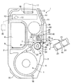
図1は、上記プリンターたとえば携帯式プリンター1の概略縦断面図であって、携帯式プリンター1は、サーマルプリンターとしてこれを構成してあり、プリンターハウジング2と、開閉カバー3と、ラベル連続体4(印字用紙)の供給部5と、位置検出部6と、印字部7と、充電バッテリー8のバッテリー収納室9と、アダプター接続端子10と、入力部11と、表示部12と、制御部13と、電源スイッチ14と、用紙切断装置15と、を有する。
Next, a paper cutting device for a printer according to a first embodiment of the present invention will be described with reference to FIGS.
FIG. 1 is a schematic longitudinal sectional view of the above-described printer, for example, a
プリンターハウジング2は、作業者が携帯可能な大きさを有し、図1中、上方にベルト掛け部16を設けて、肩掛けベルト17により携帯式プリンター1全体を作業者の肩から吊り下げ可能としている。もちろん、作業者の腰に装着可能とする構成とすることもできる。
さらにプリンターハウジング2には、図1中、下方隅部に位置したカバー軸18のまわりに上記開閉カバー3を開閉可能に設けて、供給部5へのラベル連続体4の収納および携帯式プリンター1への装填を可能としている。
The
Further, in the
ラベル連続体4は、帯状の台紙19上に複数枚のラベル片20を仮着した構成である。ラベル片20は、いわゆるサーマルラベルであって、その表面に感熱発色層を塗工して、印字可能としてある。
供給部5は、ラベル連続体4をロール状に巻いてその内部に収納し、位置検出部6および印字部7方向に帯状に繰り出し可能としている。
なお、台紙19の裏面側には、所定ピッチで位置検出用マーク21をあらかじめ印刷してある。
The label continuous body 4 has a configuration in which a plurality of
The supply unit 5 rolls the label continuous body 4 in a roll shape and stores it in the roll shape, and can feed the label continuous body 4 in the direction of the position detection unit 6 and the
A
位置検出部6は、開閉カバー3側に取り付けた位置検出センサー22を有し、ラベル連続体4の裏面側に位置する位置検出用マーク21を検出して印字部7に対するラベル連続体4(ラベル片20)の相対位置を検出可能とする。
The position detection unit 6 includes a
印字部7は、プリンターハウジング2側に取り付けたサーマルヘッド23(印字ヘッド)と、開閉カバー3側に取り付けたプラテンローラー24と、サーマルヘッド23をプラテンローラー24方向に付勢するヘッド付勢スプリング25と、駆動モーター26と、を有する。
プラテンローラー24のプラテンローラー軸27の一方側端部にはプラテンローラーギア28を設けるとともに、駆動モーター26の回転を伝達するための連結ギア29を設け、開閉カバー3のプリンターハウジング2への閉鎖により、プラテンローラーギア28と連結ギア29とを係合させて、駆動モーター26によりプラテンローラー24を回転駆動可能としている。
The
A
すなわち、サーマルヘッド23およびプラテンローラー24の間にラベル連続体4を挟持して、駆動モーター26によりプラテンローラー24を回転駆動するとともに、制御部13からサーマルヘッド23に供給した印字データに応じてサーマルヘッド23の発熱素子(図示せず)を発熱させ、ラベル連続体4(ラベル片20)にサーマル印字を行う。
That is, the label continuum 4 is sandwiched between the
プリンターハウジング2には開放用押しボタン30を設け、開放用押しボタン30をプリンターハウジング2の内方に押し込むように操作することにより、ヘッド付勢スプリング25の付勢力に抗して、サーマルヘッド23をそのヘッド軸31のまわりに図1中、反時計方向に回動させてプラテンローラー24をサーマルヘッド23から離反させ、サーマルヘッド23およびプラテンローラー24の間にラベル連続体4を挿通装填可能とする。
既述のように、開閉カバー3にはプラテンローラー24および位置検出センサー22を取り付けてあり、開閉カバー3のプリンターハウジング2からの開放回動にともなってサーマルヘッド23から離反する。
The
As described above, the
充電バッテリー8は、バッテリー収納室9に収脱可能であって、上述の印字部7(サーマルヘッド23および駆動モーター26など)はもちろん、携帯式プリンター1全体に電力を供給する。
The rechargeable battery 8 can be removed from and stored in the battery storage chamber 9, and supplies power to the entire
アダプター接続端子10は、プリンターハウジング2にこれを設け、外部電源(図示せず)に接続して充電バッテリー8に充電するためのACアダプター32を接続する。
The
入力部11は、携帯式プリンター1に必要なデータないしコマンドを入力可能とする。
表示部12は、入力部11により入力された情報およびその他必要な情報を表示可能とする。
The
The
制御部13は、電子基板などにこれを設けてあり、上述の位置検出部6、印字部7、充電バッテリー8、アダプター接続端子10、入力部11、表示部12および電源スイッチ14との間でデータおよびコマンドの授受を行うとともに、これらを適宜制御する。
The
なお、携帯式プリンター1においては、落下などによる衝撃に対する耐性を確保するために、とくにプリンターハウジング2の表面側に位置している入力部11、表示部12、電源スイッチ14、用紙切断装置15(開放用押しボタン30)、開閉カバー3などを配置している領域面をプリンターハウジング2の他の領域面(図示の例では、プリンターハウジング2の稜縁部)から凹ませるとともに、当該他の領域面にエラストマーその他の衝撃吸収性材料によるクッション材33を設けている。
また、直方体形状のプリンターハウジング2における他の稜縁部にも同様に、クッション材33を設けて携帯式プリンター1全体の耐衝撃性を確保している。
In the
Similarly, the
本実施例にかかる用紙切断装置15は、上述した開放用押しボタン30の部分にこれを設けている。
図2は、開放用押しボタン30(用紙切断装置15)部分の要部断面図、図3は、開放用押しボタン30の斜視図であり、用紙切断装置15において、開放用押しボタン30は、ボタン本体34と、ボタン本体34の周縁部の全周をめぐってこれに形成した防水用密着面35と、ボタン本体34に一体に形成したそのボタン軸36および弾性体としてのボタン付勢スプリング37と、ボタン本体34の裏面側に突出して形成した押込み用突出部38(図2)と、防水用密着面35の下方側先端部に形成した用紙切断用端部39と、を有する。
The
2 is a cross-sectional view of the main part of the opening push button 30 (paper cutting device 15), and FIG. 3 is a perspective view of the
ボタン本体34は、図1に示したようにプリンターハウジング2の表面側に露出する部分であって、携帯式プリンター1を使用する作業者がプリンターハウジング2の内方(図2中、右方から左方)に向かって押し込む部分である。
As shown in FIG. 1, the button
防水用密着面35は、ボタン本体34より相対的にプリンターハウジング2の内方側に凹んだ状態でこれを形成してプリンターハウジング2の内側に入り込むことができるとともに、プリンターハウジング2の内壁面2Aに密着可能な平面領域である。
ただし、防水用密着面35は、とくに図3に示すように、サーマルヘッド23の長さ方向(ラベル連続体4の幅方向)に沿ってより長く庇のように延びており、サーマルヘッド23の発熱素子23A(図2)のすべてを覆うことができるようにしているとともに、その下方側先端部である用紙切断用端部39がラベル連続体4を幅方向に沿って切断可能である。
The
However, as shown in FIG. 3 in particular, the
左右一対のボタン軸36は、プリンターハウジング2の内部ブラケット(図示せず)にこれを軸着し、ボタン本体34の押込み操作により、開放用押しボタン30全体を回動可能としている。
The pair of left and
左右一対のボタン付勢スプリング37は、防水用密着面35と同一平面内で蛇行させて開放用押しボタン30の端部にこれを形成しており、ボタン本体34からボタン軸36をこえた部位に位置するそれぞれの端部に当接軸部40を起立させている。
とくに図2に示すように、それぞれの当接軸部40がプリンターハウジング2の内壁面2Aに当接して、左右一対のボタン付勢スプリング37が撓むことにより、その付勢力を発揮して開放用押しボタン30の防水用密着面35をプリンターハウジング2の内壁面2Aに密着可能とする。
換言すれば、開放用押しボタン30のボタン軸36は、ボタン付勢スプリング37と防水用密着面35との間に位置してこれを設けて、防水用密着面35がプリンターハウジング2の内壁面2Aに密着させるように、ボタン付勢スプリング37が開放用押しボタン30を付勢可能としている。
なおボタン付勢スプリング37を蛇行して形成することにより、所定の付勢力を得るための必要な長さを狭い空間内で得ることが可能となり、かつ、ボタン本体34と一体形成することにより、とくに小型軽量に製造する必要があるこの種携帯式プリンター1に有利である。
The pair of left and right button urging springs 37 meander in the same plane as the
In particular, as shown in FIG. 2, the respective abutting
In other words, the
By forming the
図2(1)、(2)、(3)は、開放用押しボタン30のボタン本体34およびボタン付勢スプリング37を模式的に描いた平面説明図である。ただし、ボタン付勢スプリング37の可撓性は、それぞれ同程度とする。
図2(1)は、ボタン付勢スプリング37の当接軸部40がプリンターハウジング2の内壁面2Aに当接する場合の説明図であって、ボタン付勢スプリング37による付勢力は、後述する図2(2)および図2(3)の場合よりも小さい。
図2(2)は、ボタン付勢スプリング37に当接軸部40を形成せずに、そのスプリング先端部分37A(図中、ハッチングで示している部分)がプリンターハウジング2の内壁面2Aに当接する場合(あるいは、ボタン付勢スプリング37に当接軸部40を形成してもプリンターハウジング2の内壁面2Aに係合凹部(図示せず)を形成して、当接軸部40がこの係合凹部に係合する場合)の説明図であって、ボタン付勢スプリング37による付勢力は、中程度である(図2(1)の場合よりも強く、図2(3)の場合よりも弱い)。
図2(3)は、ボタン付勢スプリング37に当接軸部40を形成せずに、ボタン付勢スプリング37全体(図中、ハッチングで示している部分)がプリンターハウジング2の内壁面2Aに当接する場合の説明図であって、ボタン付勢スプリング37による付勢力は、図2(2)および図2(3)の場合よりも大きい。
すなわち、プリンターハウジング2の内壁面2Aに対するボタン付勢スプリング37の付勢態勢ないしは当接領域を選択することにより、防水用密着面35に要請される防水機能の程度に応じて必要な付勢力を適宜設計することができる。
2 (1), (2), and (3) are plan explanatory views schematically showing the button
FIG. 2A is an explanatory diagram when the abutting
In FIG. 2 (2), the
In FIG. 2 (3), the
That is, by selecting the urging posture or the contact area of the
とくに図2に示すように、開放用押しボタン30の裏面側(プリンターハウジング2の内方側)には、前記サーマルヘッド23を保持しているカバーロック41を前記ヘッド軸31のまわりに回動可能に設けている。
カバーロック41には、その上縁部中央に位置して、押込み用突出部38に対向する部位に当接傾斜プレート42を一体形成して設けるとともに、サーマルヘッド23を介して反対側に断面ほぼ半円弧状の左右一対のプラテンローラーロック係合部43を形成している。
プラテンローラーロック係合部43にはプラテンローラー24の左右一対のロックピン44(図1)が係脱可能である。ロックピン44がプラテンローラーロック係合部43に係合した状態で、プラテンローラー24がサーマルヘッド23に所定押圧力(印字圧力)で当接可能であり、その間に挟持するラベル連続体4への印字が可能な状態となる。
In particular, as shown in FIG. 2, a
The
A pair of left and right lock pins 44 (FIG. 1) of the
ボタン本体34の裏面側に位置する押込み用突出部38は、このカバーロック41の当接傾斜プレート42に対向しており、ボタン付勢スプリング37の付勢力に抗したボタン軸36まわりの開放用押しボタン30の図2中、時計方向の回動により、押込み用突出部38が当接傾斜プレート42を押圧し、さらにヘッド付勢スプリング25の付勢力に抗してヘッド軸31まわりにカバーロック41をサーマルヘッド23とともに図2中、反時計方向に回動させる。
したがって、プラテンローラー24のロックピン44がカバーロック41のプラテンローラーロック係合部43から離脱した状態となり、サーマルヘッド23およびプラテンローラー24とを互いに離反させ、その間にラベル連続体4を装填可能となる。
The pushing
Accordingly, the
また、プラテンローラーロック係合部43の上方端部には、テーパー面45を形成してあり、開閉カバー3の閉鎖作動時にプラテンローラー24のロックピン44がテーパー面45に当接したのち、プラテンローラーロック係合部43に係合しやすくしている。
Further, a
とくに図2および図3に示すように、用紙切断用端部39は、開放用押しボタン30における防水用密着面35の下方側先端部からこれを形成し、サーマルヘッド23およびプラテンローラー24の間から発行口46に移送されてきたラベル連続体4に用紙切断用端部39が対向し、所定の部位でラベル連続体4(台紙19、ラベル片20)を切断可能である。
なお、開放用押しボタン30(用紙切断用端部39)の材料としては、ラベル連続体4その他の印字用紙の種類に応じて、一般的には所定の剛性および弾性を有する合成樹脂材料を採用することができる。
In particular, as shown in FIGS. 2 and 3, the
As a material for the release push button 30 (paper cutting end 39), a synthetic resin material having a predetermined rigidity and elasticity is generally adopted according to the type of the label continuous body 4 and other printing paper. can do.
さらに、とくに図1に示すように、当該携帯式プリンター1は、サーマルヘッド23がプラテンローラー24より上方に位置するようにこれを携帯可能であるとともに、とくに図2に示すように、開放用押しボタン30の下方側先端部(用紙切断用端部39)は、開閉カバー3より外方側に位置している。
すなわち、用紙切断用端部39が開閉カバー3の先端部の外表面より、わずかに(図2に示す間隔D)分だけ外方側に位置していることにより、雨天その他の時に開放用押しボタン30を伝って水滴Wが用紙切断用端部39に至っても、庇のように出ている用紙切断用端部39から開閉カバー3に触れることなく地上に垂れ落ちるのみであり、プリンターハウジング2内に侵入するおそれは軽減されている。
また、発行口46に印字発行されてくるラベル連続体4は、発行口46の外方側で用紙切断用端部39に対向するので、用紙切断用端部39の部分におけるラベル連続体4の切断操作を容易かつ確実に行うことができる。
Further, particularly as shown in FIG. 1, the
That is, the
Further, since the label continuum 4 printed and issued to the issuing
こうした構成の携帯式プリンター1において、ボタン付勢スプリング37(図2)の付勢力に抗して開放用押しボタン30をプリンターハウジング2の内方に押し込むことにより、押込み用突出部38がカバーロック41の当接傾斜プレート42を、ヘッド付勢スプリング25の付勢力に抗してヘッド軸31まわりに図2中、反時計方向に回動させ、プラテンローラーロック係合部43とロックピン44との係合を解除して、開閉カバー3とともにプラテンローラー24をサーマルヘッド23から離反した開放状態とする。
この開放状態で供給部5内にロール状のラベル連続体4を収納し、開閉カバー3をプリンターハウジング2方向に閉鎖すればプラテンローラー24のロックピン44がカバーロック41のテーパー面45に当接する。ヘッド付勢スプリング25の付勢力に抗して開閉カバー3(プラテンローラー24)をさらに閉鎖方向に押し込めば、ロックピン44がプラテンローラーロック係合部43に係合するに至り、開閉カバー3を閉鎖し、またサーマルヘッド23およびプラテンローラー24を互いに押圧した状態とすることができる。
In the
When the roll-shaped continuous label body 4 is accommodated in the supply unit 5 in this open state and the open /
このような開閉カバー3の閉鎖状態においては、用紙切断装置15における開放用押しボタン30は、そのボタン本体34は外部に露出しているが、かつその開放操作自体は確保されているが、ボタン付勢スプリング37の付勢力により防水用密着面35がプリンターハウジング2の内壁面2Aに所定押圧力で密着しているため、この部分からの水の侵入を防止可能である。
すなわち、開放用押しボタン30の部分は、印字部7のサーマルヘッド23さらには制御部13に至る部分に隣り合っているため、上述の防水機能を果たすことにより、印字部7や制御部13の故障の頻度を低下させ、野外での携帯式プリンター1の使用にあたっても操作の安定性を確保可能である。
In such a closed state of the open /
That is, since the part of the
さらに、上述のように本実施例による用紙切断装置15においては、開放用押しボタン30がラベル連続体4の発行口46に臨むその下方側端部を用紙切断用端部39としているので、印字済みのラベル連続体4の所定の部位を用紙切断用端部39に当てた状態で引きちぎるように操作すれば、ラベル連続体4を手動により容易に切断することができる。
なお、開閉カバー3を開放するために開放用押しボタン30を操作する際に、その下方側端部である用紙切断用端部39の位置は所定の部位からずれることにはなるが、ラベル連続体4の切断操作時に開放用押しボタン30を操作することはないので、切断操作自体に支障はない。
Furthermore, as described above, in the
When the
かくして、開閉カバー3およびプラテンローラー24の開放のための開放用押しボタン30に用紙切断用端部39を一体的に形成したので、部品点数を削減し、携帯式プリンター1全体の小型軽量化に寄与することができる。
もちろん、卓上型プリンターその他のプリンターにも本発明による用紙切断装置を採用することが可能である。
Thus, since the
Of course, the paper cutting device according to the present invention can also be adopted in a desktop printer or other printers.
つぎに図4は、本発明の第2の実施例による用紙切断装置50における開放用押しボタン30(用紙切断装置50)部分の要部断面図であって、この用紙切断装置50においては、図2および図3で既述した開放用押しボタン30の用紙切断用端部39の内方側縁部に金属プレート51をその幅方向全域にわたって取り付けている。
したがって、この用紙切断装置50では、用紙切断用端部39に代わって、金属プレート51の下方側先端部が、ラベル連続体4を手動で切断するための用紙切断用端部52として機能することになる。
金属プレート51の材料は、任意であるが、一般的なステンレス材などを採用可能である。
Next, FIG. 4 is a cross-sectional view of the main part of the opening push button 30 (paper cutting device 50) portion in the
Therefore, in this
Although the material of the
なお、図4(1)、(2)、(3)は、図2(1)、(2)、(3)と同様の、開放用押しボタン30のボタン本体34およびボタン付勢スプリング37を模式的に描いた平面説明図であって、図2(1)、(2)、(3)にもとづいて述べたと同様に、プリンターハウジング2の内壁面2Aに対するボタン付勢スプリング37の付勢態勢ないしは当接領域を選択することにより、防水用密着面35に要請される防水機能の程度に応じて必要な付勢力を適宜設計することができる。
4 (1), (2), and (3) show the button
こうした構成の用紙切断装置50においても、印字済みのラベル連続体4が移送されてくる発行口46に金属プレート51の用紙切断用端部52が臨むことになるので、ラベル連続体4の切断操作をより容易に行うことができ、既述のような携帯式プリンター1(図1)に装備してその部品点数を削減し、小型軽量化に寄与することができる。
Also in the
1 携帯式プリンター(プリンター、図1)
2 プリンターハウジング
2A プリンターハウジング2の内壁面(図2)
3 開閉カバー
4 ラベル連続体(印字用紙)
5 供給部
6 位置検出部
7 印字部
8 充電バッテリー
9 バッテリー収納室
10 ACアダプター32を接続するアダプター接続端子
11 入力部
12 表示部
13 制御部
14 電源スイッチ
15 携帯式プリンター1の用紙切断装置(第1の実施例、図2)
16 ベルト掛け部
17 肩掛けベルト
18 開閉カバー3のカバー軸
19 ラベル連続体4の台紙
20 ラベル片
21 位置検出用マーク
22 位置検出センサー
23 サーマルヘッド(印字ヘッド)
23A サーマルヘッド23の発熱素子(図2)
24 プラテンローラー
25 ヘッド付勢スプリング
26 駆動モーター
27 プラテンローラー24のプラテンローラー軸
28 プラテンローラー24のプラテンローラーギア
29 連結ギア
30 開放用押しボタン
31 サーマルヘッド23のヘッド軸
32 ACアダプター
33 エラストマーなどによるクッション材
34 開放用押しボタン30のボタン本体
35 開放用押しボタン30の防水用密着面
36 開放用押しボタン30のボタン軸
37 開放用押しボタン30のボタン付勢スプリング
37A ボタン付勢スプリング37のスプリング先端部分(図2(2)、図4(2))
38 開放用押しボタン30の押込み用突出部
39 開放用押しボタン30の用紙切断用端部(下方側先端部)
40 ボタン付勢スプリング37の当接軸部
41 カバーロック
42 カバーロック41の当接傾斜プレート
43 プラテンローラーロック係合部
44 プラテンローラー24のロックピン
45 テーパー面
46 印字済みのラベル連続体4の発行口
50 携帯式プリンター1の用紙切断装置(第2の実施例、図4)
51 金属プレート
52 金属プレート51の用紙切断用端部(下方側先端部)
D 開放用押しボタン30の用紙切断用端部39と開閉カバー3の先端部の外表面との間の間隔(図2)
W 雨天その他の時に開放用押しボタン30を伝って用紙切断用端部39に至る水滴
1 Portable printer (printer, Fig. 1)
2
3 Open / close cover 4 Label continuum (printing paper)
DESCRIPTION OF SYMBOLS 5 Supply part 6
16
23A Heating element of thermal head 23 (FIG. 2)
24
38 Push-in
40
51
D Distance between the
W Water droplets that reach the
Claims (11)
前記プリンターハウジングに設けられ、印字用紙に印字可能な印字ヘッドと、
前記プリンターハウジングに対して開閉可能な開閉カバーと、
前記開閉カバーに設けられ、前記開閉カバーを閉鎖した状態で前記印字ヘッドに対向する位置に位置し、前記印字ヘッドとの間に前記印字用紙を挟持して回転することにより前記印字用紙を移送可能なプラテンローラーと、
前記印字ヘッドを前記プラテンローラーから離反させるように操作する開放用ボタンと、
前記印字ヘッドにより印字された印字用紙が排出され、前記開閉カバーの一端が前記印字用紙の一面側に臨み、かつ、前記開放用ボタンの先端が前記印字用紙の他面側に臨み、前記開閉カバーの一端と前記開放用ボタンの先端の隙間である発行口と、を有し、
前記開閉カバーを閉鎖した状態で、前記発行口に臨む開放用ボタンの先端が前記開閉カバーの一端よりも外側に位置するプリンター。 A printer housing;
A print head provided in the printer housing and capable of printing on printing paper;
An opening and closing cover that can be opened and closed with respect to the printer housing;
Wherein provided on the cover, located in a position opposed to the printing head in a state of closing the cover, the printing paper sandwiched SL before Ri by the fact rotated printing paper between the printing head A platen roller that can be transported,
An open button to operate the pre-Symbol printhead so as to away from said platen roller,
The printing paper printed by the printing head is discharged, one end of the opening / closing cover faces one side of the printing paper, and the tip of the opening button faces the other side of the printing paper, and the opening / closing cover An issue port that is a gap between the one end of the release button and the tip of the opening button ,
A printer in which a front end of an opening button facing the issuing port is positioned outside one end of the opening / closing cover in a state where the opening / closing cover is closed.
前記操作者が前記プリンターを携帯した状態において 前記開放用ボタンの先端は、前記開閉カバーの一端よりも上側に配置されている請求項4に記載のプリンター。The printer according to claim 4, wherein a tip of the opening button is disposed above one end of the opening / closing cover in a state where the operator carries the printer.
を有する請求項1ないし5のいずれかに記載のプリンター。 A cover lock that holds the print head and includes an engaging portion that is detachable from the platen roller;
The printer according to claim 1, comprising:
前記前記開放用ボタンを前記プリンターハウジングの内方に向けた押込み操作によりカバーロックが回動し、前記プラテンローラーが前記係合部から離脱する請求項6に記載のプリンター。 The cover lock is provided opposite to the opening button,
The printer according to claim 6 , wherein a cover lock is rotated by an operation of pushing the release button toward the inside of the printer housing, and the platen roller is detached from the engaging portion.
Priority Applications (1)
| Application Number | Priority Date | Filing Date | Title |
|---|---|---|---|
| JP2017058640A JP6355176B2 (en) | 2017-03-24 | 2017-03-24 | printer |
Applications Claiming Priority (1)
| Application Number | Priority Date | Filing Date | Title |
|---|---|---|---|
| JP2017058640A JP6355176B2 (en) | 2017-03-24 | 2017-03-24 | printer |
Related Parent Applications (1)
| Application Number | Title | Priority Date | Filing Date |
|---|---|---|---|
| JP2013063674A Division JP6118153B2 (en) | 2013-03-26 | 2013-03-26 | printer |
Publications (2)
| Publication Number | Publication Date |
|---|---|
| JP2017119440A JP2017119440A (en) | 2017-07-06 |
| JP6355176B2 true JP6355176B2 (en) | 2018-07-11 |
Family
ID=59271484
Family Applications (1)
| Application Number | Title | Priority Date | Filing Date |
|---|---|---|---|
| JP2017058640A Active JP6355176B2 (en) | 2017-03-24 | 2017-03-24 | printer |
Country Status (1)
| Country | Link |
|---|---|
| JP (1) | JP6355176B2 (en) |
Families Citing this family (1)
| Publication number | Priority date | Publication date | Assignee | Title |
|---|---|---|---|---|
| CN116100965B (en) * | 2023-02-24 | 2024-02-23 | 珠海芯烨电子科技有限公司 | Cutter mechanism with key offset |
Family Cites Families (6)
| Publication number | Priority date | Publication date | Assignee | Title |
|---|---|---|---|---|
| JP2003118202A (en) * | 2001-10-16 | 2003-04-23 | Seiko Epson Corp | Printer |
| JP3734753B2 (en) * | 2001-12-28 | 2006-01-11 | セイコーインスツル株式会社 | Thermal printer |
| JP4541123B2 (en) * | 2004-12-14 | 2010-09-08 | パナソニック株式会社 | Portable printer |
| JP4918326B2 (en) * | 2006-10-11 | 2012-04-18 | サトーホールディングス株式会社 | Printer |
| JP2011175883A (en) * | 2010-02-25 | 2011-09-08 | Orientaru Kogei Inc | Waterproofing type push-button switch for elevator |
| JP5631119B2 (en) * | 2010-08-26 | 2014-11-26 | シチズンホールディングス株式会社 | Portable printer |
-
2017
- 2017-03-24 JP JP2017058640A patent/JP6355176B2/en active Active
Also Published As
| Publication number | Publication date |
|---|---|
| JP2017119440A (en) | 2017-07-06 |
Similar Documents
| Publication | Publication Date | Title |
|---|---|---|
| EP2979883B1 (en) | Printer cover lock mechanism | |
| EP1403080B1 (en) | Handy thermal head printer | |
| JP5828937B1 (en) | Storage case for portable printer | |
| JP5897656B2 (en) | Printer | |
| JP6329729B2 (en) | printer | |
| JP6059058B2 (en) | Portable printer storage case | |
| TWI666125B (en) | Printing unit and thermal printer | |
| JP6355176B2 (en) | printer | |
| JP2015085529A (en) | Portable printer | |
| JP6116309B2 (en) | Printer | |
| JP6118153B2 (en) | printer | |
| JP2010167680A (en) | Cutter unit and printer | |
| JP4918326B2 (en) | Printer | |
| JP6104663B2 (en) | printer | |
| JP6071685B2 (en) | Portable printer | |
| JP6431590B2 (en) | printer | |
| JP2017052155A (en) | Ink ribbon, ink ribbon cassette and printer | |
| JP6257742B2 (en) | printer | |
| JP2018001719A (en) | Printer | |
| JP2017007350A (en) | Printer cover lock mechanism | |
| JP6433677B2 (en) | Printer | |
| JP6275535B2 (en) | Label printer | |
| JP4963313B2 (en) | Label printer | |
| JP6283090B2 (en) | Portable printer | |
| JP6381104B2 (en) | Printer |
Legal Events
| Date | Code | Title | Description |
|---|---|---|---|
| A521 | Request for written amendment filed |
Free format text: JAPANESE INTERMEDIATE CODE: A523 Effective date: 20170418 |
|
| A621 | Written request for application examination |
Free format text: JAPANESE INTERMEDIATE CODE: A621 Effective date: 20170418 |
|
| A977 | Report on retrieval |
Free format text: JAPANESE INTERMEDIATE CODE: A971007 Effective date: 20180223 |
|
| A131 | Notification of reasons for refusal |
Free format text: JAPANESE INTERMEDIATE CODE: A131 Effective date: 20180313 |
|
| A521 | Request for written amendment filed |
Free format text: JAPANESE INTERMEDIATE CODE: A523 Effective date: 20180423 |
|
| TRDD | Decision of grant or rejection written | ||
| A01 | Written decision to grant a patent or to grant a registration (utility model) |
Free format text: JAPANESE INTERMEDIATE CODE: A01 Effective date: 20180522 |
|
| RD02 | Notification of acceptance of power of attorney |
Free format text: JAPANESE INTERMEDIATE CODE: A7422 Effective date: 20180607 |
|
| A61 | First payment of annual fees (during grant procedure) |
Free format text: JAPANESE INTERMEDIATE CODE: A61 Effective date: 20180607 |
|
| R150 | Certificate of patent or registration of utility model |
Ref document number: 6355176 Country of ref document: JP Free format text: JAPANESE INTERMEDIATE CODE: R150 |
|
| R250 | Receipt of annual fees |
Free format text: JAPANESE INTERMEDIATE CODE: R250 |
|
| R250 | Receipt of annual fees |
Free format text: JAPANESE INTERMEDIATE CODE: R250 |
|
| R250 | Receipt of annual fees |
Free format text: JAPANESE INTERMEDIATE CODE: R250 |