WO2014155563A1 - ハンド型鉗子 - Google Patents
ハンド型鉗子 Download PDFInfo
- Publication number
- WO2014155563A1 WO2014155563A1 PCT/JP2013/059011 JP2013059011W WO2014155563A1 WO 2014155563 A1 WO2014155563 A1 WO 2014155563A1 JP 2013059011 W JP2013059011 W JP 2013059011W WO 2014155563 A1 WO2014155563 A1 WO 2014155563A1
- Authority
- WO
- WIPO (PCT)
- Prior art keywords
- elastic member
- elastic
- end portion
- hand
- joint structure
- Prior art date
- Legal status (The legal status is an assumption and is not a legal conclusion. Google has not performed a legal analysis and makes no representation as to the accuracy of the status listed.)
- Ceased
Links
Images




Classifications
-
- B—PERFORMING OPERATIONS; TRANSPORTING
- B25—HAND TOOLS; PORTABLE POWER-DRIVEN TOOLS; MANIPULATORS
- B25J—MANIPULATORS; CHAMBERS PROVIDED WITH MANIPULATION DEVICES
- B25J15/00—Gripping heads and other end effectors
- B25J15/08—Gripping heads and other end effectors having finger members
- B25J15/12—Gripping heads and other end effectors having finger members with flexible finger members
-
- A—HUMAN NECESSITIES
- A61—MEDICAL OR VETERINARY SCIENCE; HYGIENE
- A61B—DIAGNOSIS; SURGERY; IDENTIFICATION
- A61B17/00—Surgical instruments, devices or methods
- A61B17/02—Surgical instruments, devices or methods for holding wounds open, e.g. retractors; Tractors
- A61B17/0218—Surgical instruments, devices or methods for holding wounds open, e.g. retractors; Tractors for minimally invasive surgery
-
- B—PERFORMING OPERATIONS; TRANSPORTING
- B25—HAND TOOLS; PORTABLE POWER-DRIVEN TOOLS; MANIPULATORS
- B25J—MANIPULATORS; CHAMBERS PROVIDED WITH MANIPULATION DEVICES
- B25J9/00—Program-controlled manipulators
- B25J9/10—Program-controlled manipulators characterised by positioning means for manipulator elements
- B25J9/1085—Program-controlled manipulators characterised by positioning means for manipulator elements positioning by means of shape-memory materials
-
- A—HUMAN NECESSITIES
- A61—MEDICAL OR VETERINARY SCIENCE; HYGIENE
- A61B—DIAGNOSIS; SURGERY; IDENTIFICATION
- A61B17/00—Surgical instruments, devices or methods
- A61B2017/00367—Details of actuation of instruments, e.g. relations between pushing buttons, or the like, and activation of the tool, working tip, or the like
- A61B2017/00398—Details of actuation of instruments, e.g. relations between pushing buttons, or the like, and activation of the tool, working tip, or the like using powered actuators, e.g. stepper motors, solenoids
-
- A—HUMAN NECESSITIES
- A61—MEDICAL OR VETERINARY SCIENCE; HYGIENE
- A61B—DIAGNOSIS; SURGERY; IDENTIFICATION
- A61B34/00—Computer-aided surgery; Manipulators or robots specially adapted for use in surgery
- A61B34/30—Surgical robots
Definitions
- the present invention relates to a hand-type forceps.
- a retractor 50 that can be deployed in a fan shape in the abdominal cavity, for example, as shown in FIG. 5 is currently used.
- the retractor 50 has a problem that a sufficient work cannot be performed due to a lack of flexibility at the tip, and a field of view for the work may not be sufficiently secured.
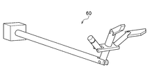
- a hand type retractor 60 shown in FIG. 6 has been proposed and developed.
- such a hand type retractor 60 has a problem that an incision of 10 mm or more is required when inserted into the abdominal cavity, a hand type needs to be assembled in the abdominal cavity, and the number of parts increases. there were.
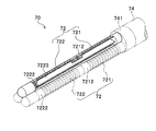
- the hand-type forceps 70 includes three elastic joint structures 72 at a tip 741 of a guide 74 that transmits a driving force of an actuator (not shown in FIG. 7).
- Each elastic joint structure 72 is a guide 74.
- the first elastic member 721 and the second elastic member 722 use cutting springs.
- the cutting spring has a high rigidity against torsion, and bends equally in all directions in three dimensions (isotropic). Therefore, in the hand-type forceps 70, a single superelastic alloy strip 7223 is provided in the center of the first elastic member 721 and the second elastic member 722. In this way, the hand-type forceps 70 described above is provided with a superelastic alloy band 7223 to limit the bending direction of the first elastic member 721 and the second elastic member 722 having isotropic properties. Bend only in a specific direction (planar direction), and has anisotropy in the bending direction. When the object is gripped with the hand-type forceps 70, since the first elastic member 721 and the second elastic member 722 are provided, these can be operated with two degrees of freedom.
- the hand-type forceps 70 is used for grasping or squeezing an object such as an organ in a minimally invasive surgical operation, so it is necessary to accurately grasp the grasping force.
- the grasping force is grasped by estimating the force (external force) applied to the distal end portion of the elastic joint structure portion of the hand-type forceps.
- Non-Patent Document 1 describes that a single cutting spring can be ideally bent into an arc by applying a continuum model.
- the elastic joint structure 72 is configured by connecting the first elastic member 721 and the second elastic member 722 using one superelastic alloy strip 7223.
- the hand-type forceps 70 applies a rigid body link approximate model, and estimates the external force by the inverse dynamics thereof.
- the continuum model is a dynamic model for describing the macroscopic mechanical behavior of solid materials that are generally inhomogeneous and non-continuous, and the rigid body link approximation model is This is a dynamic model for approximating each member divided by a joint with a rigid body and describing the mechanical behavior from the angle, angular velocity, angular acceleration, etc. of the member.
- the external force of the rigid body linked by the joint is obtained from the joint angle, angular velocity, and angular acceleration.
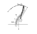
- the hand-type forceps 70 described in Non-Patent Document 1 does not have a fixed joint for moving in an arc, it is necessary to set a rotation center c on the assumption as shown in FIG. Therefore, the accuracy of the estimated external force F ext may be slightly reduced. Since the hand-type forceps 70 grip an organ, it is required to grip the organ with a more appropriate gripping force.
- the gripping force is estimated by estimating the external force applied to the distal end portion 7222 of the elastic joint structure portion 72 using back drivability.
- the back drivability means the property that when an appropriate force is applied to the output node in the actuator or power transmission mechanism, the node moves and is transmitted to the input node side.
- the present invention has been made in view of the above problems, and an object thereof is to provide a hand-type forceps capable of accurately estimating an external force.
- the hand-type forceps includes one or more elastic joint structures that hold and release a target object, an actuator that generates a driving force for operating the elastic joint structures, and the elasticity
- a guide portion that includes a transmission means for fixing the joint structure portion to the distal end portion, fixing the actuator to the proximal end portion, and transmitting the driving force generated by the actuator to the elastic joint structure portion
- the elastic joint structure portion includes a first elastic member and a second elastic member, and the first elastic member has a base end portion of the first elastic member fixed to a distal end portion of the guide portion, and the first elastic member.
- a superelastic alloy band is provided from the base end to the tip of the member, and the second elastic member has a base end of the second elastic member fixed to the tip of the first elastic member, and From the proximal end to the distal end of the second elastic member Over it is internally provided a strip of super-elastic alloy.
- the hand-type forceps according to the present invention is provided with anisotropy with respect to the bending direction because the first elastic member and the second elastic member are each provided with the superelastic alloy strip. Can do. That is, each elastic member can only bend with one degree of freedom in a specific plane.
- the continuum model based on the position fixed to the distal end portion of the guide portion can be applied to the first elastic member fixed to the distal end portion of the guide portion. Can be calculated.
- a continuum model based on the position fixed to the front end portion of the first elastic member can be applied to the second elastic member fixed to the front end portion of the first elastic member.
- the position of the tip of the member can be calculated. Therefore, the position of the tip can be calculated more accurately compared to the case of applying a rigid link approximate model that calculates the position of the tip of the second elastic member assuming the rotation center. Can be accurately estimated.
- the first elastic member and the second elastic member are both cutting springs, and the band member is concentric with respect to the central axis of the plurality of elastic joint structures. It is preferable that it is provided so as to be bent in the vertical direction. If it does in this way, since the cutting spring has the high rigidity with respect to torsion, even if it is a case where the target object is hold
- the transmission means includes a first wire that connects the actuator and the distal end portion of the first elastic member, and the actuator and the distal end portion of the second elastic member. It is preferable that the second wire is provided so as to be closer to the object than the first wire in one elastic joint structure portion.
- the first elastic member can be bent outward or returned to the closed state by pulling or loosening the first wire with the actuator. Also, by pulling or loosening the second wire with an actuator, the second elastic member can be bent inward or bent back inward. That is, the object can be gripped and released freely.
- the first wire and / or the second wire are preferably made of a superelastic alloy. In this way, not only the first wire and / or the second wire can be pulled but also pushed. Therefore, for example, by pressing these when gripping the object, the gripping force by the elastic joint structure can be increased.
- the hand-type forceps according to the present invention further includes an external force estimating means for estimating an external force of the elastic joint structure part by subtracting a force necessary for moving the mechanism without load from the driving force of the actuator. It is preferable to provide.
- the hand-type forceps according to the present invention is a continuous body in which the external force estimation unit calculates the position of the distal end portion of the first elastic member and the position of the distal end portion of the second elastic member.
- the external force is preferably estimated by a model. By doing so, the external force can be reliably estimated.
- the hand-type forceps according to the present invention has a thickness of 10 mm or less when all of the one or more elastic joint structures are closed, and at least outside the portion inserted into the abdominal cavity in the guide portion.
- the diameter is preferably 10 mm or less. In this way, since the outer diameter is small, a minimally invasive surgical operation can be realized.
- the elastic joint structure has a first elastic member and a second elastic member, and these elastic members are separately provided with a superelastic alloy strip,
- the continuum model By applying the continuum model to each of the first elastic member and the second elastic member, the position of each tip can be accurately calculated. Therefore, the hand-type forceps according to the present invention can accurately estimate the external force.
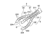
- the hand-type forceps 1 operates one or more elastic joint structures 2 to grip and release the object O (see FIG. 3).
- the hand-type forceps 1 includes the elastic joint structure portion 2, an actuator 3, and a guide portion 4 provided between the elastic joint structure portion 2 and the actuator 3.
- the side on which the actuator 3 is provided is the base end
- the side on which the elastic joint structure 2 is provided is the front end.
- base end has the same meaning.
- the elastic joint structure unit 2 plays a role of gripping and releasing the object O. That is, the elastic joint structure 2 performs an operation of securing a work space by excluding or grasping an organ covering the surgical site.
- the elastic joint structure 2 has a first elastic member 21 and a second elastic member 22.
- the first elastic member 21 is a superelastic alloy in which the proximal end portion 211 of the first elastic member 21 is fixed to the distal end portion 42 of the guide portion 4 and extends from the proximal end portion 211 to the distal end portion 212 of the first elastic member 21.
- the band material 213 is provided.
- the second elastic member 22 has a base end portion 221 of the second elastic member 22 fixed to the tip end portion 212 of the first elastic member 21 and a tip end portion 222 from the base end portion 221 of the second elastic member 22.
- a superelastic alloy strip 223 is provided in between.
- a tip member 224 whose tip is rounded using an elastomer, plastic, or the like at the tip 222 of the second elastic member 22. In this way, regardless of the shape of the distal end portion 222 of the second elastic member 22, it is possible to prevent the object O from being damaged when it is grasped or crushed.
- the tip of the elastic joint structure 2 (the second elastic member 22 of the second elastic member 22) is more accurate than when a rigid link approximation model in which the center of rotation must be set is assumed (see FIG. 8). The position of the tip 222) can be calculated, and the external force can be accurately estimated.
- Both the first elastic member 21 and the second elastic member 22 preferably use cutting springs. Since the cutting spring has a very high rigidity against torsion as compared with the coil spring, it is possible to prevent the cutting spring from being twisted when the object is gripped. Therefore, the anisotropy regarding the bending direction obtained by the superelastic alloy strips 213 and 223 can be maintained as described later. Therefore, the position of the tip end portion 222 of the second elastic member 22 can be calculated more reliably, and the external force can be estimated more accurately. Further, the cutting spring can integrally process a spring portion serving as a bending joint, one end portion (for example, base end portions 211 and 221), and the other end portion (for example, front end portions 212 and 222). .
- the number of components can be greatly reduced, and the size and maintenance are excellent.
- even a coil spring can be used as the first elastic member 21 and the second elastic member 22 as long as the coil spring has high rigidity against torsion.
- the material of the first elastic member 21 and the second elastic member 22 include stainless steel, titanium, aluminum, and alloys thereof.
- the outer diameter of the first elastic member 21 and the second elastic member 22 can be set to, for example, ⁇ 4.5 mm.
- Superelastic alloy strips 213 and 223 are individually provided in each of the first elastic member 21 and the second elastic member 22.
- the superelastic alloy strips 213 and 223 easily bend in a direction perpendicular to the wide surface of the strip, but are difficult to bend in a direction parallel to the wide surface. For this reason, the first elastic member 21 and the second elastic member 22 which are provided therein are bent only within a specific plane. Therefore, it is preferable that the superelastic alloy strips 213 and 223 are provided so as to be bent in a direction perpendicular to the central axis of the plurality of elastic joint structures 2 that are concentrically surrounded. If it does in this way, anisotropy can be given about a bending direction.
- Such superelastic alloy strips 213 and 223 can be formed of, for example, nickel, titanium, or an alloy thereof.
- the width and thickness of the superelastic alloy strips 213 and 223 may be, for example, a width of 2.9 mm and a thickness of 0.25 mm.
- the actuator 3 plays a role of generating a driving force for operating the elastic joint structure 2. It is preferable that the actuator 3 has a high affinity for an organ or the like, that is, the actuator output itself has a softness.
- An example of such an actuator 3 is a pneumatic cylinder. When a pneumatic cylinder is used, rapid input is difficult to be performed, and thus organs and the like can be gripped flexibly, and the external force applied to the elastic joint structure 2 can be accurately estimated using its high back drivability. It becomes possible.
- the guide portion 4 fixes the elastic joint structure portion 2 to the distal end portion 42 and the actuator 3 to the proximal end portion 41.
- the guide unit 4 includes a transmission unit 43 that transmits the driving force generated by the actuator 3 to the elastic joint structure unit 2.
- the guide portion 4 is preferably a hollow body such as a cylinder or a rectangular tube having a length of about 1 m, for example. If it does in this way, since the transmission means 43 can be installed in the inside of the guide part 4, the handling in the case of using for a surgical operation becomes easy. Moreover, it is preferable that the guide part 4 is a linear thing without a refractive part. In this case, as described later, a wire is used as the transmission means 43, and even when the wire is installed in the guide portion 4 as described above, the wire contacts the inner surface of the guide portion 4. Can be avoided. Therefore, the controllability and the accuracy of estimating the external force can be improved. When the guide portion 4 has a refracting portion or the like, by appropriately providing a guide roller, the wire path can be appropriately secured, and controllability and accuracy of estimating the external force can be secured. .
- the guide part 4 has an outer diameter dimension of 10 mm or less at least at a portion inserted into the abdominal cavity. If it does in this way, since an outer diameter dimension is small, it can use suitably for minimally invasive surgery.
- the transmission means 43 includes a first wire 431 and a second wire 432.
- the first wire 431 connects the actuator 3 and the distal end portion 211 of the first elastic member 21.
- the second wire 432 connects the actuator 3 and the distal end portion 222 of the second elastic member 22.
- the second wire 432 is provided so as to be closer to the object than the first wire 431 in one elastic joint structure portion 2.
- the first elastic member 21 fixed to the distal end portion 42 of the guide portion 4 is bent toward the outside of the hand-type forceps 1 (open state). )be able to. That is, it is possible to form a part that plays the role of a palm when grasping the object. Further, by driving the actuator 3 and loosening the pulled wire, the first elastic member 21 bent outward can be returned to its original position by elasticity. Accordingly, it is possible to generate a force (gripping force) for gripping the target object together with an input when the second elastic member 22 described later is bent.
- the second elastic member 22 fixed to the distal end portion 212 of the first elastic member 21 is moved in a direction opposite to the bending direction of the first elastic member 21.
- the actuator 3 and loosening the pulled wire the second elastic member 22 bent inward can be returned to its original position by its elasticity, and the object which has been gripped Can be released.
- the first wire 431 and / or the second wire 432 are preferably made of a superelastic alloy.
- the actuator 3 can be driven not only to pull the wire but also to push it, so that the gripping force can be further increased. If these wires are made of a superelastic alloy, the force that pushes the wires becomes too strong, and even if the wires are buckled, they easily return to their original shape, reducing the need for parts replacement and maintenance.
- the Examples of superelastic alloys include nickel, titanium, and alloys thereof. It is more preferable that the first wire 431 and the second wire 432 are provided in a metallic tube material (not shown) having a slightly larger inner diameter than these diameters. If it does in this way, since buckling of a wire can be prevented more certainly, grip force can be enlarged further.
- the hand-type forceps 1 preferably further includes an external force estimating means 5 for estimating the external force of the elastic joint structure 2 from the pressure of the actuator 3.
- the external force estimating means 5 may be organically connected to the hand-type forceps 1 so that the external force of the elastic joint structure 2 can be estimated, and can perform the function of estimating the external force.
- the external force estimating means 5 can be provided in a control device (computer) provided for controlling the hand-type forceps 1. That is, the external force estimating means 5 can be implemented by storing a program for estimating the external force in an HDD or the like, reading it out as necessary, and estimating the external force.
- the driving force of the first term on the left side can be obtained from the differential pressure when a pneumatic cylinder is used as the actuator 3.
- the force required to move the mechanism with no load in the second term on the left side can be obtained by inverse dynamics. Inverse dynamics calculations require position and velocity.
- the position can be obtained by a continuous model applied to each of the first elastic member 21 and the second elastic member 22.
- the speed can be obtained by numerically subtracting cylinder displacement information.
- the displacement information of the cylinder can be obtained by measuring with a position sensor 6 (see FIG. 1) such as a potentiometer.
- the first elastic member 21 and the second elastic member 22 are respectively provided with superelastic alloy strips 213 and 223 and have anisotropy in the bending direction. Are two-dimensional. When the angles of the respective superelastic alloy strips 213 and 223 are the same without any deviation, they are bent on the same plane. Therefore, when the continuum model is applied to this, as shown in FIG. 4, the position (point D (x d , y d )) of the distal end portion 222 of the second elastic member 22 is the distal end portion 42 of the guide portion 4.
- the reverse dynamics is calculated based on the estimated position of the tip 222 of the second elastic member 22 and the speed described above, and the force necessary to move the mechanism without load in the second term on the left side is calculated.
- the external force is calculated and finally calculated, that is, the external force can be estimated.
- the position of the distal end portion (the distal end portion 222 of the second elastic member 22) of the elastic joint structure portion 2 is calculated by applying a continuous model as described above. Therefore, the position of the distal end portion of the elastic joint structure 2 can be calculated more accurately as compared with the case where the position is calculated by applying a rigid body link approximation model that has been conventionally used. Therefore, the external force can be estimated more accurately than in the past. Therefore, it becomes possible to hold a target such as an organ with a more appropriate holding force.
- FIGS. 1 to 3 an embodiment having three elastic joint structures 2 is depicted, but the number of elastic joint structures 2 is not limited to this.
- the number of elastic joint structures 2 may be two, four, five, or the like.
- the elastic joint structure portion 2 may be provided as one, and one or more non-bending fixing bars or fixing plates provided opposite to the elastic joint structure portion 2 may be provided. Even with such a configuration, the object O can be gripped by bending the elastic joint structure portion 2.
- a plurality of elastic joint structures 2 when a plurality of elastic joint structures 2 are provided, they may be bent individually or may be bent in synchronism with each other.
- the elastic joint structure part 2 was comprised with the 1st elastic member 21 and the 2nd elastic member 22 was demonstrated, it is not limited to this.
- one or more elastic members having the same structure as that of the second elastic member 22 can be further fixed to the distal end portion 222 of the second elastic member 22.
- the position of the tip can be accurately calculated by applying the continuum model. Therefore, in this case as well, it is possible to accurately estimate the external force.
Landscapes
- Engineering & Computer Science (AREA)
- Health & Medical Sciences (AREA)
- Life Sciences & Earth Sciences (AREA)
- Robotics (AREA)
- Mechanical Engineering (AREA)
- Surgery (AREA)
- Heart & Thoracic Surgery (AREA)
- Biomedical Technology (AREA)
- Nuclear Medicine, Radiotherapy & Molecular Imaging (AREA)
- Medical Informatics (AREA)
- Molecular Biology (AREA)
- Animal Behavior & Ethology (AREA)
- General Health & Medical Sciences (AREA)
- Public Health (AREA)
- Veterinary Medicine (AREA)
- Surgical Instruments (AREA)
- Manipulator (AREA)
Abstract
外力の推定を正確に行うことが可能なハンド型鉗子を提供する。ハンド型鉗子1は弾性関節構造部2を備え、この弾性関節構造部2は第一弾性部材21及び第二弾性部材22を有し、第一弾性部材21は、当該第一弾性部材21の基端部211がガイド部4の先端部42に固定され、且つ当該第一弾性部材21の基端部211から先端部212にかけて超弾性合金の帯材213を内設し、第二弾性部材22は、当該第二弾性部材22の基端部221が第一弾性部材21の先端部212に固定され、且つ当該第二弾性部材22の基端部221から先端部222にかけて超弾性合金の帯材223を内設している。
Description
本発明は、ハンド型鉗子に関する。
近年、手術における患者への負担を軽減するために、低侵襲な外科手術である腹腔鏡手術が広く普及している。腹腔鏡手術では、術部を覆っている臓器を圧排したり、把持したりして、作業空間を確保する作業が重要になる。このような作業を行うものとして、現在、例えば、図5に示すような、腹腔内で扇状に展開できるリトラクタ50が用いられている。しかし、このリトラクタ50には、先端での自由度が不足しているため十分な作業を行うことができないという問題や作業のための視野を十分に確保できない場合があるという問題があった。これを克服するため、例えば、図6に示すハンド型リトラクタ60が提案され、開発が進められている。しかし、かかるハンド型リトラクタ60は、腹腔内への挿入時に10mm以上の切開が必要であったり、腹腔内でハンド型に組み立てる必要があったり、部品点数が多くなったりしてしまうなどの問題があった。
このような問題を解決すべく、最近、本発明者は図7に示すようなハンド型鉗子70(非特許文献1参照、なお、非特許文献1では「空気圧駆動ハンド」と記載されている。)を提案した。かかるハンド型鉗子70は、図7において図示しないアクチュエータの駆動力を伝達するガイド部74の先端部741に3本の弾性関節構造部72を備え、各弾性関節構造部72はそれぞれ、ガイド部74の先端部741に固定された第一弾性部材721と、この第一弾性部材721の先端部7212に固定された第二弾性部材722と、を有している。なお、第一弾性部材721及び第二弾性部材722は切削スプリングを用いている。切削スプリングは、ねじりに対する剛性が高く、屈曲方向に関しては3次元的に全ての方向に等しく屈曲する(等方性を持っている)。そこで、かかるハンド型鉗子70では、この第一弾性部材721と第二弾性部材722の中心に1本の超弾性合金の帯材7223を内設している。このように、前記したハンド型鉗子70は超弾性合金の帯材7223を内設することにより、等方性を持つ第一弾性部材721及び第二弾性部材722の屈曲方向を制限し、2次元的な方向(平面的な方向)でのみ屈曲するようにし、屈曲方向に関して異方性を持たせている。かかるハンド型鉗子70で目的物を把持する場合、第一弾性部材721と第二弾性部材722を有しているので2自由度にてこれらを操作することができる。
前記したようにハンド型鉗子70は、低侵襲の外科手術において臓器等の目的物を把持したり、圧排したりするものであるから、その把持力を正確に把握する必要がある。把持力の把握は、ハンド型鉗子の弾性関節構造部の先端部にかかる力(外力)を推定することにより行われる。
非特許文献1には、1つの切削スプリングであれば連続体モデルを適用することにより円弧状に理想的に屈曲できる旨記載されている。しかし、前記したように1本の超弾性合金の帯材7223を用いて第一弾性部材721及び第二弾性部材722を連結して弾性関節構造部72を構成していたため、これらの弾性部材の区切りが明確でなくなる結果、2自由度を有する弾性関節構造部72の先端部7222の位置を、連続体モデルを適用して適切に算出することは困難であった。そのため、かかるハンド型鉗子70では剛体リンク近似モデルを適用し、これの逆動力学により外力の推定を行っている。なお、連続体モデルとは、一般的には不均質で非連続的な性質を有した固体材料の巨視的な力学挙動を記述するための一つの力学モデルであり、剛体リンク近似モデルとは、関節で分割されたそれぞれの部材を剛体で近似し、部材の角度、角速度、角加速度などから力学挙動を記述するための一つの力学モデルである。
吉野秀行、原口大輔、只野耕太郎、川嶋健嗣、「腹腔鏡手術用空気圧駆動ハンドの開発」、日本機械学会ロボティクス・メカトロニクス講演会’12,2P1-T04、2012年5月29日発表
前記したように、剛体リンク近似モデルを用いる場合、関節でリンクされた剛体の外力を関節の角度、角速度、角加速度から求める。しかしながら、非特許文献1に記載のハンド型鉗子70には、円弧に動作させるための定まった関節がないので、図8に示すように、回転中心cを仮定的に設定する必要がある。そのため、推定される外力Fextの正確性が若干低下することがあった。ハンド型鉗子70は臓器を把持するものであるため、より適切な把持力をもってこれを把持させることが求められている。把持力の推定は、バックドライバリティを利用して弾性関節構造部72の先端部7222にかかる外力を推定することにより行われる。つまり、把持力の推定をより正確に行うためには、外力の推定をより正確に行う必要がある。なお、バックドライバリティとは、アクチュエータや動力伝達機構において、出力節に適当な力を加えたときにその節が可動し、且つそれが入力節側に伝わる性質をいう。
本発明は前記問題に鑑みてなされたものであり、外力の推定を正確に行うことが可能なハンド型鉗子を提供することを課題とする。
(1)本発明に係るハンド型鉗子は、目的物の把持と解放を行う1つ以上の弾性関節構造部と、前記弾性関節構造部を動作させるための駆動力を発生させるアクチュエータと、前記弾性関節構造部を先端部に固定するとともに前記アクチュエータを基端部に固定し、前記アクチュエータで発生させた駆動力を前記弾性関節構造部に伝達する伝達手段を備えたガイド部と、を備え、前記弾性関節構造部は第一弾性部材及び第二弾性部材を有し、前記第一弾性部材は、当該第一弾性部材の基端部が前記ガイド部の先端部に固定され、且つ当該第一弾性部材の基端部から先端部にかけて超弾性合金の帯材を内設し、前記第二弾性部材は、当該第二弾性部材の基端部が前記第一弾性部材の先端部に固定され、且つ当該第二弾性部材の基端部から先端部にかけて超弾性合金の帯材を内設している。
このようにすると、本発明に係るハンド型鉗子は、第一弾性部材と第二弾性部材のそれぞれに超弾性合金の帯材が内設されているので、屈曲方向に関して異方性を持たせることができる。つまり、個々の弾性部材はそれぞれ特定の平面内における1自由度の屈曲しか行うことができない。従って、ガイド部の先端部に固定された第一弾性部材には、ガイド部の先端部に固定された位置に基づいた連続体モデルを適用することができ、これにより第一弾性部材の先端部の位置を算出することができる。また、第一弾性部材の先端部に固定された第二弾性部材には、第一弾性部材の先端部に固定された位置に基づいた連続体モデルを適用することができ、これにより第二弾性部材の先端部の位置を算出することができる。従って、回転中心を仮定して第二弾性部材の先端部の位置を算出する剛体リンク近似モデルを適用する場合と比較して、当該先端部の位置をより正確に算出することができるため、外力の推定を正確に行うことが可能となる。
このようにすると、本発明に係るハンド型鉗子は、第一弾性部材と第二弾性部材のそれぞれに超弾性合金の帯材が内設されているので、屈曲方向に関して異方性を持たせることができる。つまり、個々の弾性部材はそれぞれ特定の平面内における1自由度の屈曲しか行うことができない。従って、ガイド部の先端部に固定された第一弾性部材には、ガイド部の先端部に固定された位置に基づいた連続体モデルを適用することができ、これにより第一弾性部材の先端部の位置を算出することができる。また、第一弾性部材の先端部に固定された第二弾性部材には、第一弾性部材の先端部に固定された位置に基づいた連続体モデルを適用することができ、これにより第二弾性部材の先端部の位置を算出することができる。従って、回転中心を仮定して第二弾性部材の先端部の位置を算出する剛体リンク近似モデルを適用する場合と比較して、当該先端部の位置をより正確に算出することができるため、外力の推定を正確に行うことが可能となる。
(2)本発明に係るハンド型鉗子は、前記第一弾性部材及び前記第二弾性部材がともに切削スプリングであり、前記帯材は同心に取り巻く複数の前記弾性関節構造部の中心軸に対して垂直方向に屈曲するように内設されているのが好ましい。
このようにすると、切削スプリングはねじりに対する剛性が高いので、目的物を把持した場合であっても第一弾性部材及び第二弾性部材がねじれてしまうのを防止することができる。従って、より確実に第二弾性部材の先端部の位置を算出することができるようになり、外力の推定をより正確に行うことが可能となる。
このようにすると、切削スプリングはねじりに対する剛性が高いので、目的物を把持した場合であっても第一弾性部材及び第二弾性部材がねじれてしまうのを防止することができる。従って、より確実に第二弾性部材の先端部の位置を算出することができるようになり、外力の推定をより正確に行うことが可能となる。
(3)本発明に係るハンド型鉗子は、前記伝達手段が、前記アクチュエータと前記第一弾性部材の先端部とを接続する第一ワイヤと、前記アクチュエータと前記第二弾性部材の先端部とを接続する第二ワイヤと、を有し、一つの前記弾性関節構造部内において、前記第一ワイヤよりも前記目的物に近い位置となるように前記第二ワイヤを設けているのが好ましい。
このようにすると、第一ワイヤをアクチュエータで引いたり、緩めたりすることにより、第一弾性部材を外側に向けて屈曲させたり、閉状態に戻したりすることができる。また、第二ワイヤをアクチュエータで引いたり、緩めたりすることにより、第二弾性部材を内側に向けて屈曲させたり、内側に向けて屈曲させていたのを元の状態に戻すことができる。つまり、目的物の把持と解放を自在に行うことができる。
このようにすると、第一ワイヤをアクチュエータで引いたり、緩めたりすることにより、第一弾性部材を外側に向けて屈曲させたり、閉状態に戻したりすることができる。また、第二ワイヤをアクチュエータで引いたり、緩めたりすることにより、第二弾性部材を内側に向けて屈曲させたり、内側に向けて屈曲させていたのを元の状態に戻すことができる。つまり、目的物の把持と解放を自在に行うことができる。
(4)本発明に係るハンド型鉗子は、前記第一ワイヤ及び/又は第二ワイヤが超弾性合金製であるのが好ましい。
このようにすると、第一ワイヤ及び/又は第二ワイヤを引くだけでなく、押すことも可能となる。そのため、例えば、目的物を把持する際にこれらを押すことにより、弾性関節構造部による把持力をより大きくすることができる。
このようにすると、第一ワイヤ及び/又は第二ワイヤを引くだけでなく、押すことも可能となる。そのため、例えば、目的物を把持する際にこれらを押すことにより、弾性関節構造部による把持力をより大きくすることができる。
(5)本発明に係るハンド型鉗子は、さらに、前記アクチュエータの駆動力から無負荷で機構を動かすために必要な力を減算することで前記弾性関節構造部の外力を推定する外力推定手段を備えているのが好ましい。
(6)そして、本発明に係るハンド型鉗子は、前記外力推定手段が、前記第一弾性部材の先端部の位置と、前記第二弾性部材の先端部の位置と、をそれぞれ算出する連続体モデルにより前記外力を推定するのが好ましい。
これらのようにすると、確実に外力を推定することができる。
(6)そして、本発明に係るハンド型鉗子は、前記外力推定手段が、前記第一弾性部材の先端部の位置と、前記第二弾性部材の先端部の位置と、をそれぞれ算出する連続体モデルにより前記外力を推定するのが好ましい。
これらのようにすると、確実に外力を推定することができる。
(7)本発明に係るハンド型鉗子は、前記1つ以上の弾性関節構造部を全て閉状態としたときの太さが10mm以下、且つ前記ガイド部において少なくとも腹腔内に挿入される部分の外径寸法が10mm以下であるのが好ましい。
このようにすると、外径寸法が小さいので低侵襲な外科手術を具現することができる。
このようにすると、外径寸法が小さいので低侵襲な外科手術を具現することができる。
本発明に係るハンド型鉗子によれば、弾性関節構造部は第一弾性部材と第二弾性部材を有し、これらの弾性部材は別個に超弾性合金の帯材を内設しているので、第一弾性部材と第二弾性部材のそれぞれに連続体モデルを適用してそれぞれの先端部の位置を正確に算出することができる。そのため、本発明に係るハンド型鉗子は、外力の推定を正確に行うことが可能となる。
以下、適宜図面を参照して本発明に係るハンド型鉗子を実施するための形態(実施形態)について詳細に説明する。
(ハンド型鉗子の主要な構成)
図1~3に示すように、本実施形態に係るハンド型鉗子1は、1つ以上の弾性関節構造部2を動作させて目的物O(図3参照)の把持と解放を行う。図1に示すように、ハンド型鉗子1は、この弾性関節構造部2と、アクチュエータ3と、弾性関節構造部2とアクチュエータ3の間に設けられるガイド部4と、を備えている。なお、本明細書においては、各部材について、アクチュエータ3が備えられている側を基端部とし、弾性関節構造部2が備えられている側を先端部としており、以下の説明において先端部及び基端部という場合はこれと同義である。
図1~3に示すように、本実施形態に係るハンド型鉗子1は、1つ以上の弾性関節構造部2を動作させて目的物O(図3参照)の把持と解放を行う。図1に示すように、ハンド型鉗子1は、この弾性関節構造部2と、アクチュエータ3と、弾性関節構造部2とアクチュエータ3の間に設けられるガイド部4と、を備えている。なお、本明細書においては、各部材について、アクチュエータ3が備えられている側を基端部とし、弾性関節構造部2が備えられている側を先端部としており、以下の説明において先端部及び基端部という場合はこれと同義である。
(弾性関節構造部)
弾性関節構造部2は、目的物Oの把持と解放を実施する役目を担っている。つまり、この弾性関節構造部2が、術部を覆っている臓器を圧排したり、把持したりして、作業空間を確保する作業を行う。
弾性関節構造部2は、目的物Oの把持と解放を実施する役目を担っている。つまり、この弾性関節構造部2が、術部を覆っている臓器を圧排したり、把持したりして、作業空間を確保する作業を行う。
弾性関節構造部2は、第一弾性部材21及び第二弾性部材22を有している。
第一弾性部材21は、当該第一弾性部材21の基端部211がガイド部4の先端部42に固定され、且つ当該第一弾性部材21の基端部211から先端部212にかけて超弾性合金の帯材213を内設している。
また、第二弾性部材22は、当該第二弾性部材22の基端部221が第一弾性部材21の先端部212に固定され、且つ当該第二弾性部材22の基端部221から先端部222にかけて超弾性合金の帯材223を内設している。なお、この第二弾性部材22の先端部222には、エラストマーやプラスチックなどを用いて先端を丸く成形したチップ部材224を設けておくのが好ましい。このようにすると、第二弾性部材22の先端部222の形状に関わらず、目的物Oを把持したり、圧排したりしたときにこれを傷付けてしまうのを防止することができる。
第一弾性部材21は、当該第一弾性部材21の基端部211がガイド部4の先端部42に固定され、且つ当該第一弾性部材21の基端部211から先端部212にかけて超弾性合金の帯材213を内設している。
また、第二弾性部材22は、当該第二弾性部材22の基端部221が第一弾性部材21の先端部212に固定され、且つ当該第二弾性部材22の基端部221から先端部222にかけて超弾性合金の帯材223を内設している。なお、この第二弾性部材22の先端部222には、エラストマーやプラスチックなどを用いて先端を丸く成形したチップ部材224を設けておくのが好ましい。このようにすると、第二弾性部材22の先端部222の形状に関わらず、目的物Oを把持したり、圧排したりしたときにこれを傷付けてしまうのを防止することができる。
本実施形態ではこのように第一弾性部材21と第二弾性部材22のそれぞれに超弾性合金の帯材213、223を内設しているので、屈曲方向に関して異方性を持たせることができる。また、このようにすることで第一弾性部材21と第二弾性部材22の区切りが明確となり、それぞれに連続体モデルを適用することが可能となる(図4参照)。従って、本実施形態においては回転中心を仮定的に設定しなければならない剛体リンク近似モデルを適用した場合(図8参照)よりも正確に弾性関節構造部2の先端部(第二弾性部材22の先端部222)の位置を算出することができ、外力の推定を正確に行うことが可能となる。
第一弾性部材21及び第二弾性部材22はともに切削スプリングを用いるのが好ましい。切削スプリングは、コイルスプリングと比較してねじりに対する剛性が非常に高いので、目的物を把持する際にねじれてしまうのを防止することができる。そのため、後記するように超弾性合金の帯材213、223によって得られる屈曲方向に関する異方性を維持することができる。よって、より確実に第二弾性部材22の先端部222の位置を算出することができるようになり、外力の推定をより正確に行うことが可能となる。また、切削スプリングは、屈曲関節となるスプリング部分と、その一端部(例えば、基端部211、221)と、その他端部(例えば、先端部212、222)と、を一体加工することができる。そのため、構成部品数を大幅に低減でき、小型化やメンテナンス性に優れている。なお、コイルスプリングであっても、ねじりに対する剛性が高いものであれば、切削スプリングと同様、第一弾性部材21及び第二弾性部材22として用いることができることは言うまでもない。第一弾性部材21及び第二弾性部材22の素材としては、例えば、ステンレス、チタン、アルミニウム又はこれらの合金などが挙げられる。第一弾性部材21と第二弾性部材22の外径寸法は、例えばφ4.5mmなどとすることができる。また、第一弾性部材21と第二弾性部材22は、1つ以上の弾性関節構造部2を全て閉状態とし、これらを束ねたときの太さが10mm以下となるようにするのが好ましい。この状態で腹腔内に挿入させることにより低侵襲な外科手術が可能となる。
超弾性合金の帯材213、223は、第一弾性部材21と第二弾性部材22のそれぞれに、個別に内設される。超弾性合金の帯材213、223は、帯材の幅広な面に対して直角な方向には容易に屈曲するものの、幅広な面に対して平行な方向には屈曲が困難である。そのため、これを内設する第一弾性部材21と第二弾性部材22は、それぞれ特定の平面内でのみ屈曲することになる。従って、超弾性合金の帯材213、223は、同心に取り巻く複数の弾性関節構造部2の中心軸に対して垂直方向に屈曲するように内設するのが好ましい。このようにすると、屈曲方向に関して異方性を持たせることができる。かかる超弾性合金の帯材213、223は、例えば、ニッケル、チタン又はこれらの合金などで形成することができる。また、超弾性合金の帯材213、223の幅寸法及び厚さ寸法は、例えば、幅2.9mm、厚さ0.25mmなどとすることができる。
(アクチュエータ)
アクチュエータ3は、弾性関節構造部2を動作させるための駆動力を発生させる役割を担っている。アクチュエータ3は臓器等に対する親和性の高いもの、つまり、アクチュエータの出力自体が柔らかさを有しているものが好ましい。そのようなアクチュエータ3として、例えば、空気圧シリンダが挙げられる。空気圧シリンダを用いると急激な入力が行われ難いので、臓器等の柔軟な把持が可能となるとともに、その高いバックドライバリティを利用して弾性関節構造部2への外力を正確に推定することが可能となる。
アクチュエータ3は、弾性関節構造部2を動作させるための駆動力を発生させる役割を担っている。アクチュエータ3は臓器等に対する親和性の高いもの、つまり、アクチュエータの出力自体が柔らかさを有しているものが好ましい。そのようなアクチュエータ3として、例えば、空気圧シリンダが挙げられる。空気圧シリンダを用いると急激な入力が行われ難いので、臓器等の柔軟な把持が可能となるとともに、その高いバックドライバリティを利用して弾性関節構造部2への外力を正確に推定することが可能となる。
(ガイド部)
ガイド部4は、その先端部42に弾性関節構造部2を固定するとともに、その基端部41にアクチュエータ3を固定している。そして、ガイド部4は、アクチュエータ3で発生させた駆動力を弾性関節構造部2に伝達する伝達手段43を備えている。
ガイド部4は、その先端部42に弾性関節構造部2を固定するとともに、その基端部41にアクチュエータ3を固定している。そして、ガイド部4は、アクチュエータ3で発生させた駆動力を弾性関節構造部2に伝達する伝達手段43を備えている。
ガイド部4は、長さが例えば1m程度の円筒体又は角筒体といった中空体であるのが好ましい。このようにすると、ガイド部4の内部に伝達手段43を内設することができるので、外科手術に用いる場合の取り扱いが容易となる。また、ガイド部4は屈折部のない直線状のものとするのが好ましい。このようにすると、後記するように伝達手段43としてワイヤを用い、これを前記したようにガイド部4内に内設した場合であっても、当該ワイヤがガイド部4の内面と接触するのを避けることができる。従って、制御性及び外力を推定する精度を向上させることができる。ガイド部4に屈折部などがある場合は、適宜にガイドローラを設けるなどすることにより、ワイヤ経路を適切に確保することができ、制御性や外力を推定する精度も確保することが可能となる。
そして、ガイド部4は、少なくとも腹腔内に挿入される部分の外径寸法が10mm以下であるのが好ましい。このようにすると、外径寸法が小さいので低侵襲な外科手術に好適に用いることができる。
伝達手段43は、第一ワイヤ431と第二ワイヤ432とを備えている。第一ワイヤ431は、アクチュエータ3と第一弾性部材21の先端部211とを接続している。また、第二ワイヤ432は、アクチュエータ3と第二弾性部材22の先端部222とを接続している。そして、この第二ワイヤ432は、一つの弾性関節構造部2内において、第一ワイヤ431よりも目的物に近い位置となるように設けられている。
従って、アクチュエータ3を駆動させて第一ワイヤ431を引くことにより、ガイド部4の先端部42に固定された第一弾性部材21をハンド型鉗子1の外側に向けて屈曲させる(開状態とする)ことができる。つまり、目的物を把持する際の、手のひらの役割を担う部分を形成することができる。また、アクチュエータ3を駆動させて、引いていたワイヤを緩めることにより、外側に向けて屈曲させた第一弾性部材21を弾性により元の位置に戻すことができる。従って、後記する第二弾性部材22を屈曲させる際の入力とともに、目的物を把持する力(把持力)を発生させることができる。
他方、アクチュエータ3を駆動させて第二ワイヤ432を引くことにより、第一弾性部材21の先端部212に固定された第二弾性部材22を、第一弾性部材21の屈曲方向とは反対の方向に屈曲させることができる。つまり、目的物を把持する際の指の役割を担うことができ、目的物を把持することができる。そして、アクチュエータ3を駆動させて、引いていたワイヤを緩めることにより、内側に向けて屈曲させた第二弾性部材22を、その弾性により元の位置に戻すことができ、把持していた目的物を解放することができる。
ここで、第一ワイヤ431及び/又は第二ワイヤ432は超弾性合金製であるのが好ましい。このようにすると、アクチュエータ3を駆動させてワイヤを引くだけでなく、押すこともできるようになるので、把持力をより大きくすることができる。なお、これらのワイヤを超弾性合金製とすると、ワイヤを押す力が強くなり過ぎてワイヤが座屈した場合であっても容易に元の形状に戻るため、部品交換やメンテナンスの手間が軽減される。超弾性合金としては、例えば、ニッケル、チタン又はこれらの合金などが挙げられる。また、第一ワイヤ431及び第二ワイヤ432はそれぞれ、これらの直径よりも若干内径寸法の大きい金属性のチューブ材(図示せず)の中に設けるようにするのがより好ましい。このようにすると、ワイヤの座屈をより確実に防止することができるので、さらに把持力を大きくすることができる。
(外力推定手段)
ハンド型鉗子1は、さらに、アクチュエータ3の圧力から弾性関節構造部2の外力を推定する外力推定手段5を備えているのが好ましい。なお、外力推定手段5は、弾性関節構造部2の外力を推定できるようにハンド型鉗子1と有機的に接続され、外力を推定する機能を果たせればよく、その設置場所は問わない。例えば、ハンド型鉗子1を制御するために設けられた制御装置(コンピュータ)に外力推定手段5を備えることができる。つまり、外力推定手段5は、外力を推定するためのプログラムをHDD等に格納しておき、必要に応じてこれを読み出し、外力を推定することにより具現できる。
ハンド型鉗子1は、さらに、アクチュエータ3の圧力から弾性関節構造部2の外力を推定する外力推定手段5を備えているのが好ましい。なお、外力推定手段5は、弾性関節構造部2の外力を推定できるようにハンド型鉗子1と有機的に接続され、外力を推定する機能を果たせればよく、その設置場所は問わない。例えば、ハンド型鉗子1を制御するために設けられた制御装置(コンピュータ)に外力推定手段5を備えることができる。つまり、外力推定手段5は、外力を推定するためのプログラムをHDD等に格納しておき、必要に応じてこれを読み出し、外力を推定することにより具現できる。
ここで、外力の推定(外乱オブザーバ)は、「(駆動力)-(無負荷で機構を動かすために必要な力)=外力」という関係を用い、左辺の2つの項から間接的に外力を算出することができる。なお、左辺第1項の駆動力は、アクチュエータ3として空気圧シリンダを用いた場合、差圧から求めることができる。また、左辺第2項の無負荷で機構を動かすために必要な力は、逆動力学にて求めることができる。逆動力学の計算には位置と速度が必要となる。このうち、位置は、第一弾性部材21と第二弾性部材22のそれぞれに適用した連続モデルによって求めることができる。速度は、シリンダの変位情報を数値差分して求めることができる。また、シリンダの変位情報は、ポテンショメータなどの位置センサ6(図1参照)で測定することによって求めることができる。
本実施形態においては、第一弾性部材21及び第二弾性部材22のそれぞれに超弾性合金の帯材213、223を内設し、屈曲方向に関して異方性を持たせているので、屈曲できる方向はそれぞれ2次元的なものになる。それぞれの超弾性合金の帯材213、223の角度にずれがなく同一である場合、これらは同一平面上で屈曲することになる。そのため、これに連続体モデルを適用する場合、図4に示すように、第二弾性部材22の先端部222の位置(点D(xd,yd))は、ガイド部4の先端部42に固定された第一弾性部材21の基端部211の可動箇所を原点B(x0,y0)とする座標系と、この第一弾性部材21の先端部212に固定された第二弾性部材22の基端部221の可動箇所を原点P(xp,yp)とする座標系と、の2つの座標系で表すことができることから、第二弾性部材22の先端部222の位置を正確に算出することができる。
従って、この推定された第二弾性部材22の先端部222の位置と前記した速度に基づいて前記した逆動力学を計算し、左辺第2項の無負荷で機構を動かすために必要な力を求め、最終的に外力を算出する、すわなち、外力を推定することができる。
以上に説明した本発明に係るハンド型鉗子1によれば、前記したように弾性関節構造部2の先端部(第二弾性部材22の先端部222)の位置を、連続モデルを適用して算出することができることから、従来用いられてきた剛体リンク近似モデルを適用してその位置を算出する場合と比較してより正確に弾性関節構造部2の先端部の位置を算出することができる。従って、従来よりも正確に外力の推定を行うことが可能となる。そのため、より適切な把持力をもって臓器等の目的物を把持させることが可能となる。
以上、本発明について、実施形態に基づいて詳細に説明したが、本発明の内容は以上の説明に限定されるものではなく、種々の改変や変更も本発明の趣旨を逸脱しない範囲で本発明に含まれる。
例えば、図1~3においては、弾性関節構造部2を3本有する態様が描画されているが、弾性関節構造部2の本数はこれに限定されるものではない。弾性関節構造部2の本数は、例えば、2本、4本、5本などとすることも可能である。
また例えば、弾性関節構造部2を1本とし、これと対峙して設けた1つ以上の屈曲しない固定棒又は固定板を備えた構成としてもよい。このような構成としても、弾性関節構造部2を屈曲させることで目的物Oを把持することができる。
さらに、弾性関節構造部2を複数本有する場合はこれらを個別に屈曲させるようにしてもよいし、全てを同期させて屈曲させるようにしてもよい。
また、前述した例では、弾性関節構造部2が第一弾性部材21及び第二弾性部材22で構成されている態様について説明したが、これに限定されるものではない。例えば、第二弾性部材22の先端部222に、当該第二弾性部材22と同じ構造の弾性部材を1つ以上さらに固定することもできる。この場合も、第二弾性部材22と同様、連続体モデルを適用してその先端部の位置を正確に算出することができる。従って、この場合も外力の推定を正確に行うことが可能である。
1 ハンド型鉗子
2 弾性関節構造部
21 第一弾性部材
211 (第一弾性部材の)基端部
212 (第一弾性部材の)先端部
213 超弾性合金の帯材
22 第二弾性部材
221 (第二弾性部材の)基端部
222 (第二弾性部材の)先端部
223 超弾性合金の帯材
3 アクチュエータ
4 ガイド部
41 (ガイド部の)基端部
42 (ガイド部の)先端部
43 伝達手段
431 第一ワイヤ
432 第二ワイヤ
5 外力推定手段
2 弾性関節構造部
21 第一弾性部材
211 (第一弾性部材の)基端部
212 (第一弾性部材の)先端部
213 超弾性合金の帯材
22 第二弾性部材
221 (第二弾性部材の)基端部
222 (第二弾性部材の)先端部
223 超弾性合金の帯材
3 アクチュエータ
4 ガイド部
41 (ガイド部の)基端部
42 (ガイド部の)先端部
43 伝達手段
431 第一ワイヤ
432 第二ワイヤ
5 外力推定手段
Claims (7)
- 目的物の把持と解放を行う1つ以上の弾性関節構造部と、
前記弾性関節構造部を動作させるための駆動力を発生させるアクチュエータと、
前記弾性関節構造部を先端部に固定するとともに前記アクチュエータを基端部に固定し、前記アクチュエータで発生させた駆動力を前記弾性関節構造部に伝達する伝達手段を備えたガイド部と、を備え、
前記弾性関節構造部は第一弾性部材及び第二弾性部材を有し、
前記第一弾性部材は、当該第一弾性部材の基端部が前記ガイド部の先端部に固定され、且つ当該第一弾性部材の基端部から先端部にかけて超弾性合金の帯材を内設し、
前記第二弾性部材は、当該第二弾性部材の基端部が前記第一弾性部材の先端部に固定され、且つ当該第二弾性部材の基端部から先端部にかけて超弾性合金の帯材を内設している
ことを特徴とするハンド型鉗子。 - 前記第一弾性部材及び前記第二弾性部材がともに切削スプリングであり、
前記帯材は同心に取り巻く複数の前記弾性関節構造部の中心軸に対して垂直方向に屈曲するように内設されている
ことを特徴とする請求項1に記載のハンド型鉗子。 - 前記伝達手段が、
前記アクチュエータと前記第一弾性部材の先端部とを接続する第一ワイヤと、
前記アクチュエータと前記第二弾性部材の先端部とを接続する第二ワイヤと、を有し、
一つの前記弾性関節構造部内において、前記第一ワイヤよりも前記目的物に近い位置となるように前記第二ワイヤを設けている
ことを特徴とする請求項1に記載のハンド型鉗子。 - 前記第一ワイヤ及び/又は第二ワイヤが超弾性合金製である
ことを特徴とする請求項3に記載のハンド型鉗子。 - さらに、前記アクチュエータの駆動力から無負荷で機構を動かすために必要な力を減算することで前記弾性関節構造部の外力を推定する外力推定手段を備えている
ことを特徴とする請求項1に記載のハンド型鉗子。 - 前記外力推定手段が、前記第一弾性部材の先端部の位置と、前記第二弾性部材の先端部の位置と、をそれぞれ算出する連続体モデルにより前記外力を推定することを特徴とする請求項5に記載のハンド型鉗子。
- 前記1つ以上の弾性関節構造部を全て閉状態としたときの太さが10mm以下、且つ前記ガイド部において少なくとも腹腔内に挿入される部分の外径寸法が10mm以下である
ことを特徴とする請求項1~6のいずれかに記載のハンド型鉗子。
Priority Applications (2)
| Application Number | Priority Date | Filing Date | Title |
|---|---|---|---|
| JP2015507770A JP6066440B2 (ja) | 2013-03-27 | 2013-03-27 | ハンド型鉗子 |
| PCT/JP2013/059011 WO2014155563A1 (ja) | 2013-03-27 | 2013-03-27 | ハンド型鉗子 |
Applications Claiming Priority (1)
| Application Number | Priority Date | Filing Date | Title |
|---|---|---|---|
| PCT/JP2013/059011 WO2014155563A1 (ja) | 2013-03-27 | 2013-03-27 | ハンド型鉗子 |
Publications (1)
| Publication Number | Publication Date |
|---|---|
| WO2014155563A1 true WO2014155563A1 (ja) | 2014-10-02 |
Family
ID=51622640
Family Applications (1)
| Application Number | Title | Priority Date | Filing Date |
|---|---|---|---|
| PCT/JP2013/059011 Ceased WO2014155563A1 (ja) | 2013-03-27 | 2013-03-27 | ハンド型鉗子 |
Country Status (2)
| Country | Link |
|---|---|
| JP (1) | JP6066440B2 (ja) |
| WO (1) | WO2014155563A1 (ja) |
Citations (3)
| Publication number | Priority date | Publication date | Assignee | Title |
|---|---|---|---|---|
| JPS5638792U (ja) * | 1979-09-04 | 1981-04-11 | ||
| JPS59107889A (ja) * | 1982-12-10 | 1984-06-22 | 株式会社クボタ | 農作物収穫用ロボットハンド |
| JPS59143685U (ja) * | 1983-03-16 | 1984-09-26 | 石川島播磨重工業株式会社 | 把持装置 |
Family Cites Families (1)
| Publication number | Priority date | Publication date | Assignee | Title |
|---|---|---|---|---|
| JPH05164110A (ja) * | 1991-12-18 | 1993-06-29 | Toshiba Corp | アクチュエータ |
-
2013
- 2013-03-27 WO PCT/JP2013/059011 patent/WO2014155563A1/ja not_active Ceased
- 2013-03-27 JP JP2015507770A patent/JP6066440B2/ja not_active Expired - Fee Related
Patent Citations (3)
| Publication number | Priority date | Publication date | Assignee | Title |
|---|---|---|---|---|
| JPS5638792U (ja) * | 1979-09-04 | 1981-04-11 | ||
| JPS59107889A (ja) * | 1982-12-10 | 1984-06-22 | 株式会社クボタ | 農作物収穫用ロボットハンド |
| JPS59143685U (ja) * | 1983-03-16 | 1984-09-26 | 石川島播磨重工業株式会社 | 把持装置 |
Non-Patent Citations (1)
| Title |
|---|
| DAISUKE HARAGUCHI ET AL.: "Development of a Pneumatically-Driven Forceps Manipulator Using a Flexible Joint", TRANSACTIONS OF THE JAPAN FLUID POWER SYSTEM SOCIETY, vol. 43, no. 3, May 2012 (2012-05-01), pages 62 - 69 * |
Also Published As
| Publication number | Publication date |
|---|---|
| JP6066440B2 (ja) | 2017-01-25 |
| JPWO2014155563A1 (ja) | 2017-02-16 |
Similar Documents
| Publication | Publication Date | Title |
|---|---|---|
| JP7403513B2 (ja) | マルチジョイント医療器具の作動における張力制御 | |
| US20250169909A1 (en) | Compliant mechanisms having inverted tool members | |
| York et al. | A wrist for needle-sized surgical robots | |
| US20230072380A1 (en) | Tension control in actuation of jointed instruments | |
| US10390898B2 (en) | Crossed-cylinder wrist mechanism with two degrees of freedom | |
| Zeng et al. | Modeling a symmetrically-notched continuum neurosurgical robot with non-constant curvature and superelastic property | |
| JP2014038075A (ja) | 外力推定装置及び鉗子システム | |
| Suh et al. | Harmonious cable actuation mechanism for soft robot joints using a pair of noncircular pulleys | |
| Arata et al. | Articulated minimally invasive surgical instrument based on compliant mechanism | |
| Zhao et al. | A continuum manipulator with closed-form inverse kinematics and independently tunable stiffness | |
| JPWO2020105616A1 (ja) | 屈曲機構及び医療装置 | |
| Prasai et al. | Design and fabrication of a disposable micro end effector for concentric tube robots | |
| JP6066440B2 (ja) | ハンド型鉗子 | |
| CN105979850A (zh) | 机械手系统及其控制方法 | |
| Losey et al. | A flexure-based wrist for needle-sized surgical robots | |
| Maeda et al. | Scaling method for force feedback of forceps manipulator based on beam theory | |
| Schwalb et al. | Surgical slave with a novel method for force sensing and trocar friction reduction | |
| Wimmer et al. | Spine-kinematics with constraint guidance for robot supported MIS-instruments | |
| Horst et al. | Snake-like Kinematics for Minimally Invasive Surgery Using Selective Laser Sintering | |
| Midday et al. | Material Handling System for Robotic Natural Orifice Surgery | |
| Khatait et al. | Effect of Combined Motion on Force Transmission of a Flexible Instrument |
Legal Events
| Date | Code | Title | Description |
|---|---|---|---|
| 121 | Ep: the epo has been informed by wipo that ep was designated in this application |
Ref document number: 13880199 Country of ref document: EP Kind code of ref document: A1 |
|
| ENP | Entry into the national phase |
Ref document number: 2015507770 Country of ref document: JP Kind code of ref document: A |
|
| NENP | Non-entry into the national phase |
Ref country code: DE |
|
| 122 | Ep: pct application non-entry in european phase |
Ref document number: 13880199 Country of ref document: EP Kind code of ref document: A1 |