WO2014155508A1 - マルチディスプレイシステム - Google Patents
マルチディスプレイシステム Download PDFInfo
- Publication number
- WO2014155508A1 WO2014155508A1 PCT/JP2013/058719 JP2013058719W WO2014155508A1 WO 2014155508 A1 WO2014155508 A1 WO 2014155508A1 JP 2013058719 W JP2013058719 W JP 2013058719W WO 2014155508 A1 WO2014155508 A1 WO 2014155508A1
- Authority
- WO
- WIPO (PCT)
- Prior art keywords
- video
- display
- partial
- display device
- video position
- Prior art date
- Legal status (The legal status is an assumption and is not a legal conclusion. Google has not performed a legal analysis and makes no representation as to the accuracy of the status listed.)
- Ceased
Links
Images




Classifications
-
- G—PHYSICS
- G06—COMPUTING OR CALCULATING; COUNTING
- G06F—ELECTRIC DIGITAL DATA PROCESSING
- G06F3/00—Input arrangements for transferring data to be processed into a form capable of being handled by the computer; Output arrangements for transferring data from processing unit to output unit, e.g. interface arrangements
- G06F3/14—Digital output to display device ; Cooperation and interconnection of the display device with other functional units
- G06F3/1423—Digital output to display device ; Cooperation and interconnection of the display device with other functional units controlling a plurality of local displays, e.g. CRT and flat panel display
- G06F3/1446—Digital output to display device ; Cooperation and interconnection of the display device with other functional units controlling a plurality of local displays, e.g. CRT and flat panel display display composed of modules, e.g. video walls
-
- G—PHYSICS
- G09—EDUCATION; CRYPTOGRAPHY; DISPLAY; ADVERTISING; SEALS
- G09G—ARRANGEMENTS OR CIRCUITS FOR CONTROL OF INDICATING DEVICES USING STATIC MEANS TO PRESENT VARIABLE INFORMATION
- G09G5/00—Control arrangements or circuits for visual indicators common to cathode-ray tube indicators and other visual indicators
- G09G5/12—Synchronisation between the display unit and other units, e.g. other display units, video-disc players
-
- G—PHYSICS
- G09—EDUCATION; CRYPTOGRAPHY; DISPLAY; ADVERTISING; SEALS
- G09G—ARRANGEMENTS OR CIRCUITS FOR CONTROL OF INDICATING DEVICES USING STATIC MEANS TO PRESENT VARIABLE INFORMATION
- G09G2320/00—Control of display operating conditions
- G09G2320/06—Adjustment of display parameters
- G09G2320/0606—Manual adjustment
-
- G—PHYSICS
- G09—EDUCATION; CRYPTOGRAPHY; DISPLAY; ADVERTISING; SEALS
- G09G—ARRANGEMENTS OR CIRCUITS FOR CONTROL OF INDICATING DEVICES USING STATIC MEANS TO PRESENT VARIABLE INFORMATION
- G09G2320/00—Control of display operating conditions
- G09G2320/08—Arrangements within a display terminal for setting, manually or automatically, display parameters of the display terminal
-
- G—PHYSICS
- G09—EDUCATION; CRYPTOGRAPHY; DISPLAY; ADVERTISING; SEALS
- G09G—ARRANGEMENTS OR CIRCUITS FOR CONTROL OF INDICATING DEVICES USING STATIC MEANS TO PRESENT VARIABLE INFORMATION
- G09G2356/00—Detection of the display position w.r.t. other display screens
Definitions
- the present invention relates to a multi-display system including a plurality of display devices.
- the multi-display system is expanding its use as a public display for displaying various information in real time in public places such as advertisements on the street, exhibitions, and sports facilities.
- the video signal input by each display device is divided, and a partial video corresponding to the position of the device is enlarged and displayed.
- Patent Document 1 Japanese Patent Application Laid-Open No. 2012-198446 discloses a multi-display system in which the same video signal is input to a plurality of display devices, and each display device divides the input video signal to display a partial video. (Publication).
- the set value is set using an on-screen display (OSD) function or the like for each display device.
- OSD on-screen display
- Patent Document 1 describes a technique for automatically changing the display layout in accordance with the number of input images, the resolution of display images, the positions of surrounding people, and the like. Yes.
- a CPU Central Processing Unit
- a sensor Sensor
- a camera Sensor
- the cost of the entire multi-display system increases.
- An object of the present invention is to provide a multi-display system that can easily change a display layout without causing an increase in cost and a display layout changing method thereof.
- a multi-display system divides one video indicated by a video signal output from a video output device into a plurality of partial videos, and displays a plurality of partial videos at different video positions.
- a display device The display device A display unit for displaying images; An operation input unit for receiving instruction inputs; A communication unit for transmitting and receiving information between the plurality of display devices; A control unit that controls the operation of the display unit and the communication unit in response to an input to the operation input unit, The controller is Display a partial video corresponding to the video position set in the device on the display unit; When the change of the video position and the video position to be changed are instructed via the operation input unit, the display unit displaying the partial video corresponding to the video position to be changed is connected via the communication unit. It is the structure which transmits the information of a video position and swaps a mutual video position.
- the display layout changing method of the present invention divides one video shown in the video signal output from the video output device into a plurality of partial videos, and displays the partial videos at different video positions.
- a display layout changing method for changing the partial video displayed on the display device in a multi-display system comprising: The display device Display a partial video corresponding to the video position set in the device, When the change of the image position and the image position to be changed are instructed via the operation input means, the image position is communicated with the display device displaying the partial image corresponding to the image position to be changed via the communication means. This information is transmitted and the video positions of each other are exchanged.
- FIG. 1 is a block diagram showing a configuration example of a multi-display system according to the present invention.
- FIG. 2 is a schematic diagram showing an example of the display layout of the multi-display system shown in FIG.
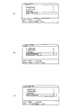
- FIG. 3 is a schematic diagram illustrating an example of an operation screen used for changing the display layout illustrated in FIG. 2.
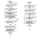
- FIG. 4 is a flowchart showing the processing procedure of the first embodiment of the display layout changing method of the present invention.
- FIG. 5 is a schematic diagram showing an example of a display layout after processing by the display layout changing method of the present invention.
- FIG. 6 is a flowchart showing the processing procedure of the second embodiment of the display layout changing method of the present invention.
- FIG. 1 is a block diagram showing a configuration example of a first embodiment of a multi-display system according to the present invention.
- the multi-display system includes a plurality of display devices 1 and a video distributor 2 that distributes a video signal to each display device 1, and outputs from the video output device 3.
- the video signal thus obtained is supplied to each display device 1 via the video distributor 2.
- Each display device 1 divides one video shown in the video signal output from the video output device 3 into a plurality of partial videos, and displays different partial videos.
- the “video” when referred to as “video”, the “video” includes moving images and still images.
- the “video signal” when referred to as a “video signal” in this specification, the “video signal” includes a signal or data for displaying a moving image or a still image.
- the video output device 3 is a computer, a television tuner, a camera, a video playback device that plays back video recorded on various media, or the like that outputs video signals for moving images or still images to be displayed on the multi-display system.
- Signals output from the video output device 3 may include not only video signals but also audio signals and other data signals.
- the video distributor 2 receives the video signal output from the video output device 3, and distributes the video signal to each display device 1 included in the multi-display system.
- a known interface such as DVI (Digital Visual Interface) or HDMI (High-Definition Multimedia Interface) may be used.
- FIG. 1 shows a configuration example in which the video output device 3, the video distributor 2, and each display device are connected by wire, but the video distributor 2 uses the well-known wireless means to connect the video output device 3 and each of the display devices. You may transmit / receive a video signal with the display apparatus 1.
- FIG. 1 shows a configuration example in which the video output device 3, the video distributor 2, and each display device are connected by wire, but the video distributor 2 uses the well-known wireless means to connect the video output device 3 and each of the display devices. You may transmit / receive a video signal with the display apparatus 1.
- the multi-display system of this embodiment can be realized without the video distributor 2 shown in FIG.
- the number of connections of the display device 1 is limited, but a configuration in which a video signal is directly distributed from a single video output device 3 to a plurality of display devices 1 connected in series or in parallel may be used. Further, when a plurality of video output devices 3 corresponding one-to-one are provided for each display device, the same video signal may be synchronously output from each video output device 3.
- the display device 1 includes a display unit 11, a display drive unit 12, a video signal input unit 13, an operation input unit 14, a communication unit 15, and a control unit 16.
- Each display device 1 shown in FIG. 1 has the same configuration.
- the display unit 11 is a known display panel such as a liquid crystal display, a plasma display, or a projection display that displays an image.
- the display drive unit 12 is a panel drive circuit corresponding to the display unit 11, and displays a video on the display unit 11 in accordance with a video signal supplied from the control unit 16.
- the video signal input unit 13 is a well-known interface circuit that receives a video signal output from the video distributor 2 or the video output device 3.
- the operation input unit 14 is configured by a circuit or a device that receives an instruction input by a user.
- the operation input unit 14 includes, for example, a light receiving unit that receives a light (infrared) signal emitted from a remote controller and converts it into an electrical signal.
- the operation input unit 14 receives a user instruction using the remote controller and outputs it to the control unit 16. .
- the operation input unit 14 is not limited to the configuration corresponding to the remote controller, and may be configured to accept a user instruction input using, for example, a button provided on the display device 1 main body.
- the communication unit 15 is a communication circuit for transmitting and receiving information.
- a known interface such as Ethernet (registered trademark) or RS (Recommended Standard) -232C may be used for transmission / reception of information by the communication unit 15.
- the display devices 1 are connected to each other via a communication unit 15 so as to be able to transmit and receive information.
- FIG. 1 shows a configuration example in which each display device 1 is connected by wire, but the display device 1 may transmit and receive information to and from each other using a known wireless means.
- the control unit 16 is a circuit that controls the operation of the entire display device.
- the control unit 16 divides the video according to the number of arrangements of the display devices 1 in the vertical direction and the horizontal direction, and automatically A partial video corresponding to the video position set in the apparatus is extracted, and the extracted partial video is enlarged and displayed on the display unit 11 by the display driving unit 12.
- the video position is information indicating the position of a partial video that is divided and displayed by each display device 1.
- control unit 16 When the change of the video position is instructed from the user via the operation input unit 14, the control unit 16 is connected to the display device 1 that displays the partial video corresponding to the video position to be changed instructed by the user. The video position information is transmitted between them, and the mutual video positions are exchanged.
- the control unit 16 includes a video signal processing circuit including a processor, a frame memory, and a control program that perform necessary processing (decoding, division, enlargement, contour correction, color correction, noise removal, resolution conversion, etc.) on the video signal. Accordingly, information including a CPU that executes processing, a main storage device that temporarily holds information necessary for the processing of the CPU, a control program that causes the CPU to execute processing, and a secondary storage device that stores various data. It can be realized by a processing device.
- the display layout changing method according to the present embodiment which will be described later, is realized, for example, when the CPU of the control unit 16 included in each display device 1 executes processing according to a control program.
- FIG. 2 is a schematic diagram showing an example of the display layout of the multi-display system shown in FIG. 1
- FIG. 3 is a schematic diagram showing an example of an operation screen used for changing the display layout shown in FIG.
- FIG. 4 is a flowchart showing the processing procedure of the first embodiment of the display layout changing method of the present invention
- FIG. 5 is a schematic diagram showing an example of the display layout after processing by the display layout changing method of the present invention.
- . 4A shows a processing procedure of the control unit 16 included in the display device 1 instructed to change the video position by the user via the operation input unit 14, and FIG. The processing procedure of the control part 16 with which the display apparatus 1 which changes an image
- the present embodiment is taken as an example of a multi-display system including a total of nine display devices 1 in which three display devices 1 are arranged in the vertical direction and the horizontal direction, respectively.
- a display layout changing method will be described.
- the number of display devices provided in the multi-display system is not limited as long as it is two or more.
- the MAC address can also be used as an address for specifying the display device 1 that is a transmission source and a transmission destination of information.
- SWAP POSITION the number of display devices in the horizontal direction (H MONITORS), the number of display devices in the vertical direction (V MONITORS), and the video position (POSITION) set in the own device are displayed.
- generates the control message (SWAP POSITION change response) which shows the completion of a video position change including the video position (Position 9) before a change as information (step B3).
- the control unit 16 of the display device PD 1 notifies all the other display devices 1 of the changed video position via the communication unit 15 (step A7).
- the display layout of the multi-display system can be changed easily.
- the display layout is not automatically changed by detecting the number of input videos, the resolution of the display video, the positions of surrounding people, and the like, and each display device has high processing capability. There is no need to provide a CPU or the like. Furthermore, since the video position is changed using the existing OSD function provided in each display device 1, the display layout can be changed only by changing the control program executed by the control unit 16. Accordingly, the cost of the multi display system does not increase.
- each display device 1 stores the video position set for each display device, and the display device 1 instructed to change the video position by the user is the display device 1 that is the change destination.
- An example is shown in which partial video is replaced by requesting the video position to be changed.
- the multi-display system according to the second embodiment is an example in which the partial images can be exchanged even if each display device 1 does not know the image position set for each display device. Since the configurations of the multi-display system and each display device are the same as those in the first embodiment, description thereof is omitted.
- FIG. 6 is a flowchart showing the processing procedure of the second embodiment of the display layout changing method of the present invention.
- 6A shows a processing procedure of the control unit 16 included in the display device 1 instructed by the user to change the video position via the operation input unit 14, and FIG.
- SWAP POSITION change request is generated (step C2).
- the value of the video position (POSITION) displayed in the SWAP menu is updated to “9” (step C5).
- the control unit 16 of each display device 1 it is not necessary for the control unit 16 of each display device 1 to transmit / receive a control message including information on the video position of its own device to / from other display devices via the communication unit 15. There is no need to store the video position set for each display device. Therefore, the same effects as those of the first embodiment can be obtained while reducing the processing load of the control unit 16 and the capacity of the storage device included in the control unit 16.
Landscapes
- Engineering & Computer Science (AREA)
- Theoretical Computer Science (AREA)
- Multimedia (AREA)
- Physics & Mathematics (AREA)
- General Physics & Mathematics (AREA)
- Human Computer Interaction (AREA)
- General Engineering & Computer Science (AREA)
- Computer Hardware Design (AREA)
- Controls And Circuits For Display Device (AREA)
Abstract
マルチディスプレイシステムを構成する各表示装置は、自装置に設定された映像位置にしたがって対応する部分映像を表示する。また、各表示装置は、操作入力手段を介して映像位置の変更及び変更する映像位置が指示されると、該変更する映像位置に対応する部分映像を表示している表示装置との間で映像位置の情報を送信し、互いの映像位置を入れ替える。
Description
本発明は複数の表示装置を備えるマルチディスプレイシステムに関する。
近年、映像表示システムとして、複数の表示装置を垂直方向及び水平方向に配列して大きな画面を構成するマルチディスプレイシステムが普及している。マルチディスプレイシステムは、例えば、街頭での広告表示、展示会、スポーツ施設等、公共の場所で様々な情報をリアルタイムに表示するためのパブリックディスプレイとしての用途が拡大している。
一般にマルチディスプレイシステムを用いて1つの映像を表示する場合、各表示装置で入力された映像信号をそれぞれ分割し、自装置の位置に対応した部分映像を拡大して表示する。
なお、複数の表示装置に同一の映像信号を入力し、各表示装置が入力された映像信号を分割して部分映像を表示するマルチディスプレイシステムについては、例えば特許文献1(特開2012-198446号公報)にも記載されている。
ところで、上述したマルチディスプレイシステムにおいて、各表示装置で表示する部分映像のレイアウト(表示レイアウト)を変更する場合、表示装置毎にオンスクリーンディスプレイ(On Screen Display:OSD)機能等を用いて設定値を変更する必要がある。例えば2つの表示装置で表示している部分映像を入れ替えたい場合、それら2つの表示装置に表示させる部分映像の映像位置をそれぞれ変更しなければならない。そのため、表示レイアウトの変更操作が煩雑であり、ユーザの手間が大きいという課題がある。
そのような手間を低減するため、例えば上記特許文献1には、入力される映像数、表示映像の解像度、周囲の人の位置等に応じて表示レイアウトを自動的に変更する技術が記載されている。しかしながら、特許文献1に記載された技術では、各表示装置に処理能力が高いCPU(Central Processing Unit)等を備える必要があり、さらに周囲の人の位置情報を取得するためのセンサやカメラ等を備える必要があるため、マルチディスプレイシステム全体のコストが上昇してしまう。
本発明は、コストの上昇を招くことなく表示レイアウトを簡易に変更できるマルチディスプレイシステム及びその表示レイアウト変更方法を提供することを目的とする。
上記目的を達成するため本発明のマルチディスプレイシステムは、映像出力機器から出力された映像信号に示される1つの映像を複数の部分映像に分割し、それぞれが異なる映像位置の部分映像を表示する複数の表示装置を有し、
前記表示装置は、
映像を表示する表示部と、
指示入力を受け付ける操作入力部と、
前記複数の表示装置間で情報を送受信するための通信部と、
前記操作入力部への入力に応じて前記表示部、前記通信部の動作を制御する制御部と、を備え、
前記制御部は、
自装置に設定された前記映像位置に対応する部分映像を前記表示部に表示させ、
前記操作入力部を介して前記映像位置の変更及び変更する映像位置が指示されると、該変更する映像位置に対応する部分映像を表示している表示装置との間で前記通信部を介して映像位置の情報を送信し、互いの映像位置を入れ替える構成である。
前記表示装置は、
映像を表示する表示部と、
指示入力を受け付ける操作入力部と、
前記複数の表示装置間で情報を送受信するための通信部と、
前記操作入力部への入力に応じて前記表示部、前記通信部の動作を制御する制御部と、を備え、
前記制御部は、
自装置に設定された前記映像位置に対応する部分映像を前記表示部に表示させ、
前記操作入力部を介して前記映像位置の変更及び変更する映像位置が指示されると、該変更する映像位置に対応する部分映像を表示している表示装置との間で前記通信部を介して映像位置の情報を送信し、互いの映像位置を入れ替える構成である。
一方、本発明の表示レイアウト変更方法は、映像出力機器から出力された映像信号に示される1つの映像を複数の部分映像に分割し、それぞれが異なる映像位置の部分映像を表示する複数の表示装置を有するマルチディスプレイシステムにおける、前記表示装置で表示する前記部分映像を変更するための表示レイアウト変更方法であって、
前記表示装置が、
自装置に設定された前記映像位置に対応する部分映像を表示し、
操作入力手段を介して前記映像位置の変更及び変更する映像位置が指示されると、該変更する映像位置に対応する部分映像を表示している表示装置との間で通信手段を介して映像位置の情報を送信し、互いの映像位置を入れ替える方法である。
前記表示装置が、
自装置に設定された前記映像位置に対応する部分映像を表示し、
操作入力手段を介して前記映像位置の変更及び変更する映像位置が指示されると、該変更する映像位置に対応する部分映像を表示している表示装置との間で通信手段を介して映像位置の情報を送信し、互いの映像位置を入れ替える方法である。
次に本発明について図面を用いて説明する。
(第1の実施の形態)
図1は、本発明のマルチディスプレイシステムの第1の実施の形態の一構成例を示すブロック図である。
(第1の実施の形態)
図1は、本発明のマルチディスプレイシステムの第1の実施の形態の一構成例を示すブロック図である。
図1に示すように、第1の実施の形態のマルチディスプレイシステムは、複数の表示装置1と、各表示装置1に映像信号を分配する映像分配器2とを備え、映像出力機器3から出力された映像信号が、映像分配器2を介して各表示装置1に供給される構成である。各表示装置1は、映像出力機器3から出力された映像信号に示される1つの映像を複数の部分映像に分割し、それぞれが異なる部分映像を表示する。
本明細書において「映像」と称した場合、該「映像」には動画像及び静止画像を含むものとする。また、本明細書において「映像信号」と称した場合、該「映像信号」には動画像や静止画像を表示するための信号やデータを含むものとする。
映像出力機器3は、マルチディスプレイシステムに表示させる動画像あるいは静止画像用の映像信号を出力する、コンピュータ、テレビジョンチューナー、カメラ、各種のメディアに記録された映像を再生する映像再生装置等である。映像出力機器3から出力する信号には映像信号だけでなく音声信号やその他のデータ信号等を含んでいてもよい。
映像分配器2は、映像出力機器3から出力された映像信号を受信し、マルチディスプレイシステムが備える各表示装置1へ該映像信号を分配する。映像信号の伝送には、例えばDVI(Digital Visual Interface)やHDMI(High-Definition Multimedia Interface)等の周知のインタフェースを用いればよい。図1は、映像出力機器3、映像分配器2及び各表示装置が有線で接続された構成例を示しているが、映像分配器2は、周知の無線手段を用いて映像出力機器3や各表示装置1と映像信号を送受信してもよい。
なお、本実施形態のマルチディスプレイシステムは、図1に示す映像分配器2が無くても実現可能である。例えば、表示装置1の接続数が制限されるが、直列または並列に接続された複数の表示装置1に対して、1台の映像出力機器3から直接映像信号を分配する構成でもよい。また、表示装置毎に1対1で対応する複数の映像出力機器3を備えている場合、各映像出力機器3から同一の映像信号を同期して出力する構成でもよい。
表示装置1は、表示部11、表示駆動部12、映像信号入力部13、操作入力部14、通信部15及び制御部16をそれぞれ備える。図1に示す各表示装置1は、それぞれ同様の構成である。
表示部11は、映像を表示する、液晶ディスプレイ、プラズマディスプレイ、プロジェクションディスプレイ等の周知の表示パネルである。表示駆動部12は、表示部11に対応したパネル駆動回路であり、制御部16から供給される映像信号にしたがって表示部11に映像を表示させる。
映像信号入力部13は、映像分配器2や映像出力機器3から出力された映像信号を受信する周知のインタフェース回路である。
操作入力部14は、ユーザによる指示入力を受け付ける回路や装置で構成される。操作入力部14は、例えばリモートコントローラから出射された光(赤外線)信号を受光して電気信号に変換する受光部を備え、リモートコントローラを用いたユーザの指示を受信して制御部16に出力する。操作入力部14は、リモートコントローラに対応した構成に限定されるものではなく、例えば表示装置1本体に設けられたボタン等を用いてユーザの指示入力を受け付ける構成でもよい。
通信部15は、情報を送受信するための通信回路である。通信部15による情報の送受信には、イーサネット(登録商標)やRS(Recommended Standard)-232C等の周知のインタフェースを用いればよい。各表示装置1は、通信部15を介して互いに情報の送受信が可能に接続されている。図1は、各表示装置1が有線で接続された構成例を示しているが、表示装置1は周知の無線手段を用いて互いに情報を送受信してもよい。
制御部16は、表示装置全体の動作を制御する回路である。制御部16は、映像信号入力部13を介して映像分配器2または映像出力機器3から映像信号を受信すると、垂直方向及び水平方向の表示装置1の配列数に応じて映像を分割し、自装置に設定された映像位置に対応する部分映像を抽出し、抽出した部分映像を表示駆動部12によって表示部11に拡大表示させる。映像位置とは各表示装置1が分割して表示する部分映像の位置を示す情報である。
また、制御部16は、操作入力部14を介してユーザから映像位置の変更が指示されると、ユーザが指示した該変更する映像位置に対応する部分映像を表示している表示装置1との間で映像位置の情報を送信し、互いの映像位置を入れ替える。
制御部16は、映像信号に対して所要の処理(復号、分割、拡大、輪郭補正、色補正、雑音除去、解像度変換等)を実行するプロセッサやフレームメモリを含む映像信号処理回路、制御プログラムにしたがって処理を実行するCPU、該CPUの処理で必要な情報を一時的に保持する主記憶装置、CPUに処理を実行させるための制御プログラムや各種のデータが保存される副記憶装置等を含む情報処理装置で実現できる。後述する本実施形態の表示レイアウト変更方法は、例えば各表示装置1が備える制御部16のCPUが制御プログラムにしたがって処理を実行することで実現される。
図2は図1に示したマルチディスプレイシステムの表示レイアウトの一例を示す模式図であり、図3は図2に示した表示レイアウトの変更に用いる操作画面の一例を示す模式図である。図4は本発明の表示レイアウト変更方法の第1の実施の形態の処理手順を示すフローチャートであり、図5は本発明の表示レイアウト変更方法による処理後の表示レイアウトの一例を示す模式図である。なお、図4(a)は操作入力部14を介してユーザから映像位置の変更が指示された表示装置1が備える制御部16の処理手順を示し、図4(b)は該表示装置1からの要求にしたがって映像位置を変更する表示装置1が備える制御部16の処理手順を示している。
以下では、図2及び図5に示すように垂直方向及び水平方向にそれぞれ3台の表示装置1が配列された、合計で9台の表示装置1を備えるマルチディスプレイシステムを例にして本実施形態の表示レイアウト変更方法を説明する。マルチディスプレイシステムが備える表示装置の数は2台以上であれば何台でもよい。
また、図2や図5に示すマルチディスプレイシステムでは、上段の3台の表示装置1を左から右にPD=1,2,3と称し、中段の3台の表示装置1を左から右にPD=4,5,6と称し、下段の3台の表示装置1を左から右にPD=7,8,9と称すものとする。
さらに、各表示装置1には、映像位置(Position)の初期値として、上段の3台の表示装置1に対して左から右に映像位置Position=1,2,3が設定され、中段の3台の表示装置1に対して左から右に映像位置Position=4,5,6が設定され、下段の3台の表示装置1に対して左から右に映像位置Position=7,8,9が設定されているものとする。
したがって、図2に示すマルチディスプレイシステムでは、初期状態において、上段の表示装置PD=1は映像位置Position=1に対応する部分映像を拡大表示し、表示装置PD=2は映像位置Position=2に対応する部分映像を拡大表示し、表示装置PD=3は映像位置Position=3に対応する部分映像を拡大表示する。中段の表示装置PD=4~6及び下段の表示装置PD=7~9も、同様に各々に設定された映像位置に対応する部分映像を拡大表示する。
各表示装置PD=1~9の制御部16は、例えば映像位置の設定変更時または定期的に、通信部15を介して自装置の映像位置の情報を含む制御メッセージを他の表示装置と送受信することで、表示装置PD=1~9毎に設定された映像位置を認識しているものとする。その場合、各表示装置PD=1~9の制御部16は、表示装置PD=1~9毎の識別情報(MAC(Media Access Control)アドレス等)とその映像位置の情報とを、例えばテーブル形式で副記憶装置等に保存しておけばよい。各表示装置1が情報を送受信する場合、上記MACアドレスは、情報の送信元及び送信先の表示装置1を特定するアドレスとしても利用できる。
また、以下では、表示装置PD=1と表示装置PD=9が表示している部分映像を入れ替える場合を例にして、本実施形態の表示レイアウト変更方法について説明する。部分映像を入れ替える2台の表示装置1は、表示装置PD=1と表示装置PD=9とに限定されるものではなく、自由に選択することが可能である。
ユーザが、例えばリモートコントローラを用いて表示装置PD=1のOSD機能を起動させ、所定のメインメニューから部分映像の入れ替えを指示するためのSWAPメニューを選択すると、該表示装置PD=1の制御部16は、該SWAPメニュー画像を表示部11に表示させる。
図3(a)に示すように、SWAPメニューには、例えば水平方向の表示装置数(H MONITORS)、垂直方向の表示装置数(V MONITORS)及び自装置に設定された映像位置(POSITION)を表示するエリアと、ユーザによって設定可能な、変更先の部分映像の映像位置である変更先映像位置(SWAP POSITION)を入力するためのエリアとが設けられている。
図4(a)に示すように、SWAPメニューが表示されている状態において、表示装置PD=1の制御部16は、SWAPメニューの変更先映像位置(SWAP POSITION)が入力設定されたか否かを判定する(ステップA1)。変更先映像位置(SWAP POSITION)が入力設定されていない場合はステップA1の処理に戻る。
ユーザがリモートコントローラ等を用いて変更先映像位置(SWAP POSITION)のエリアに「9」を入力して確定すると(図3(b))、表示装置PD=1の制御部16は、自装置に設定された映像位置(Position=1)を情報として含む、映像位置の変更を要求する制御メッセージ(SWAP POSITION変更要求)を生成する(ステップA2)。
次に、表示装置PD=1の制御部16は、各表示装置1とその映像位置の関係を示すテーブル等を参照して、ユーザにより変更先として指定された、映像位置が「9」(Position=9)に対応する部分映像を表示している表示装置PD=9を抽出する(ステップA3)。
続いて、表示装置PD=1の制御部16は、ステップA2で生成したSWAP POSITION変更要求を、ステップA3で抽出した表示装置PD=9に通信部15を介して送信する(ステップA4)。
図4(b)に示すように、表示装置PD=9の制御部16は、通信部15を介して表示装置PD=1からSWAP POSITION変更要求を受信すると(ステップB1)、自装置の映像位置を該SWAP POSITION変更要求に含まれる映像位置の情報に基づいて変更する(ステップB2)。具体的には、自装置の映像位置をPosition=9からPosition=1に変更する。そして、表示装置PD=9の制御部16は、変更前の映像位置(Position=9)を情報として含む、映像位置の変更完了を示す制御メッセージ(SWAP POSITION変更応答)を生成し(ステップB3)、通信部15を介して該SWAP POSITION変更応答を表示装置PD=1へ返信する(ステップB4)。また、表示装置PD=9の制御部16は、通信部15を介して変更後の映像位置を他の全ての表示装置1へそれぞれ通知する(ステップB5)。
図4(a)に示すように、表示装置PD=1の制御部16は、ステップA4にてSWAP POSITION変更応答を送信すると、表示装置PD=9からのSWAP POSITION変更応答を待ち受ける。表示装置PD=1の制御部16は、表示装置PD=9からSWAP POSITION変更応答を受信したか否かを判定し(ステップA5)、SWAP POSITION変更応答を受信していない場合はステップA5の処理を繰り返す。
表示装置PD=9からSWAP POSITION変更応答を受信すると、自装置に設定された映像位置を、Position=1からユーザが指示したPosition=9に変更し、図3(c)で示すようにSWAPメニューで表示している映像位置(POSITION)の値を「9」に更新する(ステップA6)。また、表示装置PD=1の制御部16は、通信部15を介して変更後の映像位置を他の全ての表示装置1へそれぞれ通知する(ステップA7)。
その後、例えばユーザがOSD機能を停止させると、図5に示すように、表示装置PD=1では変更後の映像位置(Position=9)に対応する部分映像が拡大表示され、表示装置PD=9では変更後の映像位置(Position=1)に対応する部分映像が拡大表示される。
本実施形態によれば、複数の表示装置1を備えたマルチディスプレイシステムにおいて、2つの表示装置1で表示している部分映像を入れ替えたい場合に、いずれか一方の表示装置1の映像位置を変更するだけで、所望の2つの表示装置1で表示している部分映像を入れ替えることができる。そのため、マルチディスプレイシステムの表示レイアウトを簡易に変更できる。
また、本実施形態では、入力される映像数、表示映像の解像度、周囲の人の位置等を検出して表示レイアウトを「自動」で変更するものではないため、各表示装置に処理能力が高いCPU等を備える必要がない。さらに、各表示装置1が備える既存のOSD機能を用いて映像位置を変更するため、制御部16で実行する制御プログラムを変更するだけで表示レイアウトの変更を実現できる。したがって、マルチディスプレイシステムのコストが上昇することもない。
よって、コストの上昇を招くことなく表示レイアウトを簡易に変更できるマルチディスプレイシステムが得られる。
(第2の実施の形態)
次に、本発明のマルチディスプレイシステムの第2の実施の形態について図面を用いて説明する。
(第2の実施の形態)
次に、本発明のマルチディスプレイシステムの第2の実施の形態について図面を用いて説明する。
上述した第1の実施の形態では、各表示装置1が表示装置毎に設定された映像位置を保存しておき、ユーザに映像位置の変更を指示された表示装置1が変更先の表示装置1へ映像位置の変更を要求することで部分映像を入れ替える例を示した。
第2の実施の形態のマルチディスプレイシステムは、各表示装置1が表示装置毎に設定された映像位置を知らなくても、部分映像を入れ替え可能にする例である。マルチディスプレイシステム及び各表示装置の構成は、第1の実施の形態と同様であるため、その説明は省略する。
図6は、本発明の表示レイアウト変更方法の第2の実施の形態の処理手順を示すフローチャートである。なお、図6(a)は操作入力部14を介してユーザから映像位置の変更が指示された表示装置1が備える制御部16の処理手順を示し、図6(b)は該表示装置1からの要求にしたがって映像位置を変更する表示装置1が備える制御部16の処理手順を示している。
以下では、第1の実施の形態と同様に、垂直方向及び水平方向にそれぞれ3台の表示装置1が配列された、合計で9台の表示装置1を備えるマルチディスプレイシステムにおいて、表示装置PD=1と表示装置PD=9が表示している部分映像を入れ替える場合を例にして、本実施形態の表示レイアウト変更方法について説明する。
ユーザが、例えばリモートコントローラを用いて表示装置PD=1のOSD機能を起動させ、所定のメインメニューから部分映像の入れ替えを指示するためのSWAPメニューを選択すると、該表示装置PD=1の制御部16は、該SWAPメニュー画像を表示部11に表示させる。
図6(a)に示すように、SWAPメニューが表示されている状態において、表示装置PD=1の制御部16は、SWAPメニューの変更先映像位置(SWAP POSITION)が入力設定されたか否かを判定する(ステップC1)。変更先映像位置(SWAP POSITION)が入力設定されていない場合はステップC1の処理に戻る。
例えばユーザがリモートコントローラ等を用いて変更先映像位置(SWAP POSITION)のエリアに「9」を入力して確定すると(図3(b))、表示装置PD=1の制御部16は、自装置の識別情報(例えば上記MACアドレス)、自装置に設定されている映像位置(Position=1)、変更先の映像位置(Position=9)の情報を含む、映像位置の変更を要求する制御メッセージ(SWAP POSITION変更要求)を生成する(ステップC2)。
そして、表示装置PD=1の制御部16は、ステップC2で生成したSWAP POSITION変更要求を、通信部15を介して他の全ての表示装置1へ送信(ブロードキャスト)する(ステップC3)。
図6(b)に示すように、表示装置PD=1を除く各表示装置1は、SWAP POSITION変更要求を受信すると(ステップD1)、制御部16により自装置に設定された映像位置が該SWAP POSITION変更要求に含まれる変更先の映像位置に該当するか否かを判定する(ステップD2)。
表示装置PD=1を除く各表示装置1の制御部16は、自装置に設定された映像位置が受信したSWAP POSITION変更要求に含まれる変更先の映像位置に該当しない場合は処理を終了する。
一方、自装置に設定された映像位置が変更先の映像位置に該当する場合(ここでは、表示装置PD=9)、該表示装置PD=9の制御部16は、自装置の映像位置を該SWAP POSITION変更要求に含まれる映像位置の情報に基づいて変更する(ステップD3)。具体的には、自装置の映像位置をPosition=9からPosition=1に変更する。そして、表示装置PD=9の制御部16は、変更前の映像位置(Position=9)を情報として含む、映像位置の変更完了を示す制御メッセージ(SWAP POSITION変更応答)を生成し(ステップD4)、通信部15を介して該SWAP POSITION変更応答を、SWAP POSITION変更要求の送信元である表示装置PD=1へ返信する(ステップD5)。
図6(a)に示すように、表示装置PD=1の制御部16は、ステップC3にてSWAP POSITION変更応答を送信すると、SWAP POSITION変更応答を待ち受ける。表示装置PD=1の制御部16は、SWAP POSITION変更応答を受信したか否かを判定し(ステップC4)、SWAP POSITION変更応答を受信していない場合はステップC4の処理を繰り返す。
表示装置PD=1の制御部16は、表示装置PD=9からSWAP POSITION変更応答を受信すると、自装置に設定された映像位置をPosition=1からユーザが指示したPosition=9に変更し、図3(c)で示すようにSWAPメニューで表示している映像位置(POSITION)の値を「9」に更新する(ステップC5)。
以降、第1の実施の形態と同様に、表示装置PD=1では変更後の映像位置(Position=9)に対応する部分映像が拡大表示され、表示装置PD=9では変更後の映像位置(Position=1)に対応する部分映像が拡大表示される(図5参照)。
本実施形態のマルチディスプレイシステムによれば、各表示装置1の制御部16が通信部15を介して自装置の映像位置の情報を含む制御メッセージを他の表示装置と送受信する必要がなく、また表示装置毎に設定された映像位置を保存しておく必要もない。そのため、制御部16の処理負荷の低減や制御部16が備える記憶装置の容量低減を実現しつつ、第1の実施の形態と同様の効果が得られる。
以上、実施形態を参照して本願発明を説明したが、本願発明は上記実施形態に限定されものではない。本願発明の構成や詳細は本願発明のスコープ内で当業者が理解し得る様々な変更が可能である。
Claims (9)
- 映像出力機器から出力された映像信号に示される1つの映像を複数の部分映像に分割し、それぞれが異なる映像位置の部分映像を表示する複数の表示装置を有し、
前記表示装置は、
映像を表示する表示部と、
指示入力を受け付ける操作入力部と、
前記複数の表示装置間で情報を送受信するための通信部と、
前記操作入力部への入力に応じて前記表示部、前記通信部の動作を制御する制御部と、を備え、
前記制御部は、
自装置に設定された前記映像位置に対応する部分映像を前記表示部に表示させ、
前記操作入力部を介して前記映像位置の変更及び変更する映像位置が指示されると、該変更する映像位置に対応する部分映像を表示している表示装置との間で前記通信部を介して映像位置の情報を送信し、互いの映像位置を入れ替えるマルチディスプレイシステム。 - 請求項1に記載のマルチディスプレイシステムにおいて、
前記制御部は、
他の表示装置からの通知により、各表示装置が表示している部分映像に対応する映像位置の情報をそれぞれ保存し、
前記操作入力部を介して前記映像位置の変更及び変更する映像位置が指示されると、該変更する映像位置に対応する部分映像を表示している表示装置に対して、現在表示している部分映像に対応する映像位置とともに、表示する部分映像の変更要求を送信し、その後、指示された映像位置に対応する部分映像を表示して、指示された映像位置を他の表示装置へ通知し、
前記通信部を介して他の表示装置から前記映像位置の変更要求を受信すると、該変更要求とともに送られてきた映像位置に対応する部分映像を表示し、該映像位置を他の表示装置へ通知する、マルチディスプレイシステム。 - 請求項1に記載のマルチディスプレイシステムにおいて、
前記制御部は、
前記操作入力部を介して前記映像位置の変更及び変更する映像位置が指示されると、該変更する映像位置及び現在表示している部分映像に対応する映像位置とともに、表示する部分映像の変更要求を他の表示装置へ送信し、その後、指示された映像位置に対応する部分映像を表示し、
前記通信部を介して他の表示装置から前記映像位置の変更要求を受信すると、前記変更要求とともに送られてきた前記変更する映像位置が自装置に設定された映像位置に該当するか否かを判定し、
該変更する映像位置が自装置に設定された映像位置に該当する場合は、該変更要求を送信した表示装置に設定されていた映像位置に対応する部分映像を表示する、マルチディスプレイシステム。 - 請求項1から3のいずれか1項に記載のマルチディスプレイシステムにおいて、
前記制御部は、
前記映像位置の変更指示を入力するためのメニュー画像を、オンスクリーンディスプレイ機能を用いて前記表示部に表示させる、マルチディスプレイシステム。 - 映像出力機器から出力された映像信号に示される1つの映像を複数の部分映像に分割し、それぞれが異なる映像位置の部分映像を表示する複数の表示装置を有するマルチディスプレイシステムにおける、前記表示装置で表示する前記部分映像を変更するための表示レイアウト変更方法であって、
前記表示装置が、
自装置に設定された前記映像位置に対応する部分映像を表示し、
操作入力手段を介して前記映像位置の変更及び変更する映像位置が指示されると、該変更する映像位置に対応する部分映像を表示している表示装置との間で通信手段を介して映像位置の情報を送信し、互いの映像位置を入れ替える表示レイアウト変更方法。 - 請求項5に記載の表示レイアウト変更方法において、
前記表示装置が、
前記通信手段を介した他の表示装置からの通知により、各表示装置が表示している部分映像に対応する映像位置の情報を記憶装置にそれぞれ保存し、
操作入力手段を介して前記映像位置の変更及び変更する映像位置が指示されると、該変更する映像位置に対応する部分映像を表示している表示装置に対して、現在表示している部分映像に対応する映像位置とともに、表示する部分映像の変更要求を送信し、その後、指示された映像位置に対応する部分映像を表示して、指示された映像位置を他の表示装置へ通知し、
前記通信手段を介して他の表示装置から前記映像位置の変更要求を受信すると、該変更要求とともに送られてきた映像位置に対応する部分映像を表示し、該映像位置を他の表示装置へ通知する、表示レイアウト変更方法。 - 請求項5に記載の表示レイアウト変更方法において、
前記表示装置が、
操作入力手段を介して前記映像位置の変更及び変更する映像位置が指示されると、該変更する映像位置及び現在表示している部分映像に対応する映像位置とともに、表示する部分映像の変更要求を他の表示装置へ送信し、その後、指示された映像位置に対応する部分映像を表示し、
前記通信手段を介して他の表示装置から前記映像位置の変更要求を受信すると、前記変更要求とともに送られてきた前記変更する映像位置が自装置に設定された映像位置に該当するか否かを判定し、
該変更する映像位置が自装置に設定された映像位置に該当する場合は、該変更要求を送信した表示装置に設定されていた映像位置に対応する部分映像を表示する、表示レイアウト変更方法。 - 請求項5から7のいずれか1項に記載の表示レイアウト変更方法において、
前記表示装置が、
前記映像位置の変更指示を入力するためのメニュー画像を、オンスクリーンディスプレイ機能を用いて表示する、表示レイアウト変更方法。 - 映像信号に示される1つの映像を異なる映像位置ごとに分割した複数の部分映像のうちの1つを表示する表示部と、
指示入力を受け付ける操作入力部と、
情報を送受信するための通信部と、
前記操作入力部への入力に応じて前記表示部、前記通信部の動作を制御する制御部と、を備え、
前記制御部は、
自装置に設定された前記映像位置に対応する部分映像を前記表示部に表示させ、
前記操作入力部を介して前記映像位置の変更及び変更する映像位置が指示されると、前記通信部を介して前記自装置に設定された前記映像位置の情報を送信し、前記変更する映像位置に対応する部分映像を前記表示部に表示させる表示装置。
Priority Applications (2)
| Application Number | Priority Date | Filing Date | Title |
|---|---|---|---|
| US14/777,735 US9933987B2 (en) | 2013-03-26 | 2013-03-26 | Multi-display system |
| PCT/JP2013/058719 WO2014155508A1 (ja) | 2013-03-26 | 2013-03-26 | マルチディスプレイシステム |
Applications Claiming Priority (1)
| Application Number | Priority Date | Filing Date | Title |
|---|---|---|---|
| PCT/JP2013/058719 WO2014155508A1 (ja) | 2013-03-26 | 2013-03-26 | マルチディスプレイシステム |
Publications (1)
| Publication Number | Publication Date |
|---|---|
| WO2014155508A1 true WO2014155508A1 (ja) | 2014-10-02 |
Family
ID=51622597
Family Applications (1)
| Application Number | Title | Priority Date | Filing Date |
|---|---|---|---|
| PCT/JP2013/058719 Ceased WO2014155508A1 (ja) | 2013-03-26 | 2013-03-26 | マルチディスプレイシステム |
Country Status (2)
| Country | Link |
|---|---|
| US (1) | US9933987B2 (ja) |
| WO (1) | WO2014155508A1 (ja) |
Cited By (1)
| Publication number | Priority date | Publication date | Assignee | Title |
|---|---|---|---|---|
| WO2021235112A1 (ja) * | 2020-05-18 | 2021-11-25 | ソニーグループ株式会社 | 映像信号出力装置、映像信号出力装置の制御方法、表示装置およびマルチディスプレイシステム |
Families Citing this family (1)
| Publication number | Priority date | Publication date | Assignee | Title |
|---|---|---|---|---|
| CN105468326B (zh) * | 2016-01-08 | 2020-03-31 | 京东方科技集团股份有限公司 | 一种显示装置及其信息通道的调整方法和装置 |
Citations (3)
| Publication number | Priority date | Publication date | Assignee | Title |
|---|---|---|---|---|
| JP2002099268A (ja) * | 2000-09-25 | 2002-04-05 | Fuji Photo Film Co Ltd | 画像表示方法および装置 |
| JP2009086048A (ja) * | 2007-09-27 | 2009-04-23 | Brother Ind Ltd | プロジェクタシステム及びその駆動方法 |
| JP2013009057A (ja) * | 2011-06-22 | 2013-01-10 | Sharp Corp | マルチディスプレイシステム |
Family Cites Families (5)
| Publication number | Priority date | Publication date | Assignee | Title |
|---|---|---|---|---|
| JP2007514978A (ja) * | 2003-12-19 | 2007-06-07 | スピーチギア,インコーポレイティド | 表示装置の位置の関数としての視覚データの表示 |
| US20070243919A1 (en) * | 2006-04-12 | 2007-10-18 | Paul Thelen | Computer implemented puzzle |
| US20100053151A1 (en) * | 2008-09-02 | 2010-03-04 | Samsung Electronics Co., Ltd | In-line mediation for manipulating three-dimensional content on a display device |
| KR101642722B1 (ko) * | 2010-02-04 | 2016-07-27 | 삼성전자 주식회사 | 듀얼 표시부를 가지는 휴대단말 및 그 표시부의 표시 제어 방법 |
| JP5351198B2 (ja) | 2011-03-23 | 2013-11-27 | シャープ株式会社 | マルチディスプレイシステム |
-
2013
- 2013-03-26 WO PCT/JP2013/058719 patent/WO2014155508A1/ja not_active Ceased
- 2013-03-26 US US14/777,735 patent/US9933987B2/en active Active
Patent Citations (3)
| Publication number | Priority date | Publication date | Assignee | Title |
|---|---|---|---|---|
| JP2002099268A (ja) * | 2000-09-25 | 2002-04-05 | Fuji Photo Film Co Ltd | 画像表示方法および装置 |
| JP2009086048A (ja) * | 2007-09-27 | 2009-04-23 | Brother Ind Ltd | プロジェクタシステム及びその駆動方法 |
| JP2013009057A (ja) * | 2011-06-22 | 2013-01-10 | Sharp Corp | マルチディスプレイシステム |
Cited By (2)
| Publication number | Priority date | Publication date | Assignee | Title |
|---|---|---|---|---|
| WO2021235112A1 (ja) * | 2020-05-18 | 2021-11-25 | ソニーグループ株式会社 | 映像信号出力装置、映像信号出力装置の制御方法、表示装置およびマルチディスプレイシステム |
| US11880627B2 (en) | 2020-05-18 | 2024-01-23 | Sony Group Corporation | Video signal output device, method for controlling video signal output device, display device, and multi-display system |
Also Published As
| Publication number | Publication date |
|---|---|
| US20160070522A1 (en) | 2016-03-10 |
| US9933987B2 (en) | 2018-04-03 |
Similar Documents
| Publication | Publication Date | Title |
|---|---|---|
| TWI667915B (zh) | 用於動態視聽功能交換之方法及裝置 | |
| JP6002377B2 (ja) | ディスプレー装置及びその制御方法、及びシャッターメガネ及びその制御方法 | |
| TWI518673B (zh) | 影像切換器及其切換方法 | |
| WO2017109961A1 (ja) | 映像表示装置 | |
| TW201426689A (zh) | 顯示裝置、顯示系統以及具有該顯示系統的電子裝置 | |
| JP2016009102A (ja) | マルチ画面表示装置 | |
| WO2014141425A1 (ja) | 映像表示システム、ソース機器、シンク機器及び映像表示方法 | |
| JP2009201010A (ja) | プロジェクタシステム、プロジェクタ及びリモートコントローラ | |
| US10572209B2 (en) | Multi-display system | |
| TWI502486B (zh) | 投影機、影像輸出裝置及其控制方法 | |
| JP2018093305A (ja) | 表示装置及びその制御方法、プログラム、記憶媒体 | |
| EP2688293A2 (en) | Method and apparatus for displaying an image, and computer readable recording medium | |
| WO2014155508A1 (ja) | マルチディスプレイシステム | |
| US11202028B2 (en) | Display device configuring multi display system and control method thereof | |
| JP2018054763A (ja) | 画像投射装置、画像投射装置の制御方法、プログラム | |
| CN110476418A (zh) | 配置多显示系统的显示设备及其控制方法 | |
| CN104618669B (zh) | 投影机、图像输出装置及其控制方法 | |
| KR20100005273A (ko) | 멀티비전 시스템 및 그 화면 구현 방법 | |
| WO2013098991A1 (ja) | 映像表示装置および外部機器 | |
| TWI475886B (zh) | 顯示控制裝置 | |
| JP2006235233A (ja) | 大画面の映像表示方法、映像表示装置及び大画面映像表示装置 | |
| CN111443883B (zh) | 显示装置的控制方法、显示装置以及显示系统 | |
| JP6759974B2 (ja) | 送信制御プログラム、送信制御方法および情報処理装置 | |
| US11099799B2 (en) | Method for controlling display device, display device, method for controlling display system, and display system | |
| WO2014141376A1 (ja) | 表示装置及び画質設定方法 |
Legal Events
| Date | Code | Title | Description |
|---|---|---|---|
| 121 | Ep: the epo has been informed by wipo that ep was designated in this application |
Ref document number: 13880184 Country of ref document: EP Kind code of ref document: A1 |
|
| WWE | Wipo information: entry into national phase |
Ref document number: 14777735 Country of ref document: US |
|
| NENP | Non-entry into the national phase |
Ref country code: DE |
|
| 122 | Ep: pct application non-entry in european phase |
Ref document number: 13880184 Country of ref document: EP Kind code of ref document: A1 |
|
| NENP | Non-entry into the national phase |
Ref country code: JP |