WO2014148470A1 - Multiporous hollow-fiber membrane and process for producing multiporous hollow-fiber membrane - Google Patents
Multiporous hollow-fiber membrane and process for producing multiporous hollow-fiber membrane Download PDFInfo
- Publication number
- WO2014148470A1 WO2014148470A1 PCT/JP2014/057276 JP2014057276W WO2014148470A1 WO 2014148470 A1 WO2014148470 A1 WO 2014148470A1 JP 2014057276 W JP2014057276 W JP 2014057276W WO 2014148470 A1 WO2014148470 A1 WO 2014148470A1
- Authority
- WO
- WIPO (PCT)
- Prior art keywords
- hollow fiber
- fiber membrane
- melt
- fine powder
- inorganic fine
- Prior art date
Links
Images

Classifications
-
- B—PERFORMING OPERATIONS; TRANSPORTING
- B01—PHYSICAL OR CHEMICAL PROCESSES OR APPARATUS IN GENERAL
- B01D—SEPARATION
- B01D69/00—Semi-permeable membranes for separation processes or apparatus characterised by their form, structure or properties; Manufacturing processes specially adapted therefor
- B01D69/08—Hollow fibre membranes
-
- C—CHEMISTRY; METALLURGY
- C08—ORGANIC MACROMOLECULAR COMPOUNDS; THEIR PREPARATION OR CHEMICAL WORKING-UP; COMPOSITIONS BASED THEREON
- C08J—WORKING-UP; GENERAL PROCESSES OF COMPOUNDING; AFTER-TREATMENT NOT COVERED BY SUBCLASSES C08B, C08C, C08F, C08G or C08H
- C08J9/00—Working-up of macromolecular substances to porous or cellular articles or materials; After-treatment thereof
- C08J9/0014—Use of organic additives
- C08J9/0023—Use of organic additives containing oxygen
-
- B—PERFORMING OPERATIONS; TRANSPORTING
- B32—LAYERED PRODUCTS
- B32B—LAYERED PRODUCTS, i.e. PRODUCTS BUILT-UP OF STRATA OF FLAT OR NON-FLAT, e.g. CELLULAR OR HONEYCOMB, FORM
- B32B3/00—Layered products comprising a layer with external or internal discontinuities or unevennesses, or a layer of non-planar form; Layered products having particular features of form
- B32B3/26—Layered products comprising a layer with external or internal discontinuities or unevennesses, or a layer of non-planar form; Layered products having particular features of form characterised by a particular shape of the outline of the cross-section of a continuous layer; characterised by a layer with cavities or internal voids ; characterised by an apertured layer
-
- B—PERFORMING OPERATIONS; TRANSPORTING
- B32—LAYERED PRODUCTS
- B32B—LAYERED PRODUCTS, i.e. PRODUCTS BUILT-UP OF STRATA OF FLAT OR NON-FLAT, e.g. CELLULAR OR HONEYCOMB, FORM
- B32B5/00—Layered products characterised by the non- homogeneity or physical structure, i.e. comprising a fibrous, filamentary, particulate or foam layer; Layered products characterised by having a layer differing constitutionally or physically in different parts
- B32B5/02—Layered products characterised by the non- homogeneity or physical structure, i.e. comprising a fibrous, filamentary, particulate or foam layer; Layered products characterised by having a layer differing constitutionally or physically in different parts characterised by structural features of a fibrous or filamentary layer
- B32B5/022—Non-woven fabric
-
- B—PERFORMING OPERATIONS; TRANSPORTING
- B32—LAYERED PRODUCTS
- B32B—LAYERED PRODUCTS, i.e. PRODUCTS BUILT-UP OF STRATA OF FLAT OR NON-FLAT, e.g. CELLULAR OR HONEYCOMB, FORM
- B32B5/00—Layered products characterised by the non- homogeneity or physical structure, i.e. comprising a fibrous, filamentary, particulate or foam layer; Layered products characterised by having a layer differing constitutionally or physically in different parts
- B32B5/02—Layered products characterised by the non- homogeneity or physical structure, i.e. comprising a fibrous, filamentary, particulate or foam layer; Layered products characterised by having a layer differing constitutionally or physically in different parts characterised by structural features of a fibrous or filamentary layer
- B32B5/028—Net structure, e.g. spaced apart filaments bonded at the crossing points
-
- B—PERFORMING OPERATIONS; TRANSPORTING
- B32—LAYERED PRODUCTS
- B32B—LAYERED PRODUCTS, i.e. PRODUCTS BUILT-UP OF STRATA OF FLAT OR NON-FLAT, e.g. CELLULAR OR HONEYCOMB, FORM
- B32B5/00—Layered products characterised by the non- homogeneity or physical structure, i.e. comprising a fibrous, filamentary, particulate or foam layer; Layered products characterised by having a layer differing constitutionally or physically in different parts
- B32B5/16—Layered products characterised by the non- homogeneity or physical structure, i.e. comprising a fibrous, filamentary, particulate or foam layer; Layered products characterised by having a layer differing constitutionally or physically in different parts characterised by features of a layer formed of particles, e.g. chips, powder or granules
-
- C—CHEMISTRY; METALLURGY
- C08—ORGANIC MACROMOLECULAR COMPOUNDS; THEIR PREPARATION OR CHEMICAL WORKING-UP; COMPOSITIONS BASED THEREON
- C08J—WORKING-UP; GENERAL PROCESSES OF COMPOUNDING; AFTER-TREATMENT NOT COVERED BY SUBCLASSES C08B, C08C, C08F, C08G or C08H
- C08J9/00—Working-up of macromolecular substances to porous or cellular articles or materials; After-treatment thereof
- C08J9/0066—Use of inorganic compounding ingredients
-
- B—PERFORMING OPERATIONS; TRANSPORTING
- B29—WORKING OF PLASTICS; WORKING OF SUBSTANCES IN A PLASTIC STATE IN GENERAL
- B29C—SHAPING OR JOINING OF PLASTICS; SHAPING OF MATERIAL IN A PLASTIC STATE, NOT OTHERWISE PROVIDED FOR; AFTER-TREATMENT OF THE SHAPED PRODUCTS, e.g. REPAIRING
- B29C67/00—Shaping techniques not covered by groups B29C39/00 - B29C65/00, B29C70/00 or B29C73/00
- B29C67/20—Shaping techniques not covered by groups B29C39/00 - B29C65/00, B29C70/00 or B29C73/00 for porous or cellular articles, e.g. of foam plastics, coarse-pored
- B29C67/202—Shaping techniques not covered by groups B29C39/00 - B29C65/00, B29C70/00 or B29C73/00 for porous or cellular articles, e.g. of foam plastics, coarse-pored comprising elimination of a solid or a liquid ingredient
-
- B—PERFORMING OPERATIONS; TRANSPORTING
- B29—WORKING OF PLASTICS; WORKING OF SUBSTANCES IN A PLASTIC STATE IN GENERAL
- B29K—INDEXING SCHEME ASSOCIATED WITH SUBCLASSES B29B, B29C OR B29D, RELATING TO MOULDING MATERIALS OR TO MATERIALS FOR MOULDS, REINFORCEMENTS, FILLERS OR PREFORMED PARTS, e.g. INSERTS
- B29K2027/00—Use of polyvinylhalogenides or derivatives thereof as moulding material
- B29K2027/12—Use of polyvinylhalogenides or derivatives thereof as moulding material containing fluorine
- B29K2027/16—PVDF, i.e. polyvinylidene fluoride
-
- B—PERFORMING OPERATIONS; TRANSPORTING
- B29—WORKING OF PLASTICS; WORKING OF SUBSTANCES IN A PLASTIC STATE IN GENERAL
- B29K—INDEXING SCHEME ASSOCIATED WITH SUBCLASSES B29B, B29C OR B29D, RELATING TO MOULDING MATERIALS OR TO MATERIALS FOR MOULDS, REINFORCEMENTS, FILLERS OR PREFORMED PARTS, e.g. INSERTS
- B29K2105/00—Condition, form or state of moulded material or of the material to be shaped
- B29K2105/04—Condition, form or state of moulded material or of the material to be shaped cellular or porous
-
- B—PERFORMING OPERATIONS; TRANSPORTING
- B29—WORKING OF PLASTICS; WORKING OF SUBSTANCES IN A PLASTIC STATE IN GENERAL
- B29L—INDEXING SCHEME ASSOCIATED WITH SUBCLASS B29C, RELATING TO PARTICULAR ARTICLES
- B29L2031/00—Other particular articles
- B29L2031/755—Membranes, diaphragms
-
- B—PERFORMING OPERATIONS; TRANSPORTING
- B32—LAYERED PRODUCTS
- B32B—LAYERED PRODUCTS, i.e. PRODUCTS BUILT-UP OF STRATA OF FLAT OR NON-FLAT, e.g. CELLULAR OR HONEYCOMB, FORM
- B32B2262/00—Composition or structural features of fibres which form a fibrous or filamentary layer or are present as additives
- B32B2262/02—Synthetic macromolecular fibres
- B32B2262/0207—Elastomeric fibres
- B32B2262/0215—Thermoplastic elastomer fibers
-
- B—PERFORMING OPERATIONS; TRANSPORTING
- B32—LAYERED PRODUCTS
- B32B—LAYERED PRODUCTS, i.e. PRODUCTS BUILT-UP OF STRATA OF FLAT OR NON-FLAT, e.g. CELLULAR OR HONEYCOMB, FORM
- B32B2262/00—Composition or structural features of fibres which form a fibrous or filamentary layer or are present as additives
- B32B2262/02—Synthetic macromolecular fibres
- B32B2262/0223—Vinyl resin fibres
- B32B2262/023—Aromatic vinyl resin, e.g. styrenic (co)polymers
-
- B—PERFORMING OPERATIONS; TRANSPORTING
- B32—LAYERED PRODUCTS
- B32B—LAYERED PRODUCTS, i.e. PRODUCTS BUILT-UP OF STRATA OF FLAT OR NON-FLAT, e.g. CELLULAR OR HONEYCOMB, FORM
- B32B2264/00—Composition or properties of particles which form a particulate layer or are present as additives
-
- B—PERFORMING OPERATIONS; TRANSPORTING
- B32—LAYERED PRODUCTS
- B32B—LAYERED PRODUCTS, i.e. PRODUCTS BUILT-UP OF STRATA OF FLAT OR NON-FLAT, e.g. CELLULAR OR HONEYCOMB, FORM
- B32B2264/00—Composition or properties of particles which form a particulate layer or are present as additives
- B32B2264/10—Inorganic particles
- B32B2264/102—Oxide or hydroxide
-
- B—PERFORMING OPERATIONS; TRANSPORTING
- B32—LAYERED PRODUCTS
- B32B—LAYERED PRODUCTS, i.e. PRODUCTS BUILT-UP OF STRATA OF FLAT OR NON-FLAT, e.g. CELLULAR OR HONEYCOMB, FORM
- B32B2307/00—Properties of the layers or laminate
- B32B2307/50—Properties of the layers or laminate having particular mechanical properties
- B32B2307/54—Yield strength; Tensile strength
-
- B—PERFORMING OPERATIONS; TRANSPORTING
- B32—LAYERED PRODUCTS
- B32B—LAYERED PRODUCTS, i.e. PRODUCTS BUILT-UP OF STRATA OF FLAT OR NON-FLAT, e.g. CELLULAR OR HONEYCOMB, FORM
- B32B2307/00—Properties of the layers or laminate
- B32B2307/70—Other properties
- B32B2307/724—Permeability to gases, adsorption
-
- B—PERFORMING OPERATIONS; TRANSPORTING
- B32—LAYERED PRODUCTS
- B32B—LAYERED PRODUCTS, i.e. PRODUCTS BUILT-UP OF STRATA OF FLAT OR NON-FLAT, e.g. CELLULAR OR HONEYCOMB, FORM
- B32B2307/00—Properties of the layers or laminate
- B32B2307/70—Other properties
- B32B2307/726—Permeability to liquids, absorption
-
- B—PERFORMING OPERATIONS; TRANSPORTING
- B32—LAYERED PRODUCTS
- B32B—LAYERED PRODUCTS, i.e. PRODUCTS BUILT-UP OF STRATA OF FLAT OR NON-FLAT, e.g. CELLULAR OR HONEYCOMB, FORM
- B32B2410/00—Agriculture-related articles
-
- B—PERFORMING OPERATIONS; TRANSPORTING
- B32—LAYERED PRODUCTS
- B32B—LAYERED PRODUCTS, i.e. PRODUCTS BUILT-UP OF STRATA OF FLAT OR NON-FLAT, e.g. CELLULAR OR HONEYCOMB, FORM
- B32B2432/00—Cleaning articles, e.g. mops, wipes
Definitions
- the present invention relates to a porous hollow fiber membrane and a method for producing a porous hollow fiber membrane.
- Porous hollow fiber membranes have a wide range of operating conditions including high blocking performance that can reliably remove bacteria such as Cryptosporidium and turbid components, high water permeability for treating large amounts of water, chemical cleaning and high operating pressure. Three performances of high strength that can be used for a long time are required.
- porous hollow fiber membrane when a porous hollow fiber membrane is used in the field of treating water, an external pressure filtration method that can ensure a large filtration area is mainly used. Therefore, since the hollow fiber membrane is not crushed during the filtration operation, the porous hollow fiber membrane is required to have high strength in the external pressure direction, that is, high compression strength.
- Patent Document 1 discloses a porous polyethylene hollow fiber using a stretch opening method and a method for producing the same.
- a method for producing a porous membrane a heat-induced phase separation method, which is a production method different from the stretch hole method, is known (for example, see Non-Patent Documents 1 to 4).
- the present invention provides a porous hollow fiber membrane having both fine pores suitable for filtration applications and high water permeability and excellent strength, and a method for stably producing the porous hollow fiber membrane. With the goal.
- the present invention is as follows.
- the porous hollow fiber membrane according to (1) having a pure water permeability of 9000 L / m 2 / hr or more and a compressive strength of 0.8 MPa or more.
- a porous multilayer hollow fiber membrane having one or more separation layers on the outer surface of the porous hollow fiber membrane according to (1) or (2).
- a melt-kneaded product containing a thermoplastic resin, an organic liquid, and inorganic fine powder having an average primary particle size of 18 nm to 100 nm is passed through a filter with a pore size of 30 ⁇ m to 500 ⁇ m, and then discharged from a spinneret having an annular discharge port.
- a porous hollow fiber membrane comprising: a step of forming a hollow fiber melt-kneaded product; and a step of cooling and solidifying the hollow fiber melt-kneaded product and then extracting and removing organic liquid and inorganic fine powder to produce a porous hollow fiber membrane. Manufacturing method. (5) The method for producing a porous hollow fiber membrane according to (4), wherein the inorganic fine powder is silica.
- a porous hollow fiber membrane having both fine pores suitable for filtration and high water permeability and excellent strength, and a method for stably producing the porous hollow fiber membrane. can do.
- the porous hollow fiber membrane of this embodiment contains a thermoplastic resin, the outer surface hole has an aspect ratio of 10 or more, the inner surface hole has an aspect ratio of 1 to 5, and is a polymer trunk that forms the outer surface hole. Is characterized by having a thickness of 1 ⁇ m to 20 ⁇ m.
- thermoplastic resin is a resin that has elasticity at room temperature and does not exhibit plasticity, but exhibits plasticity by appropriate heating and can be molded.
- a thermoplastic resin is a resin that returns to its original elastic body when it cools down and does not undergo chemical changes such as the molecular structure during that time (edited by the Chemistry Dictionary Editorial Committee, Chemistry Dictionary 6 Reprint). Edition, Kyoritsu Shuppan, pages 860 and 867, 1963).
- thermoplastic resins include resins described in the section of thermoplastics (pages 829 to 882) of 12695 chemical products (Chemical Industry Daily, 1995), and the Chemical Handbook Application Edition, revised 3rd edition (edited by the Chemical Society of Japan). , Maruzen, 1980), pages 809-810.
- specific examples of the thermoplastic resin include polyethylene, polypropylene, polyolefin such as polypropylene, polyvinylidene fluoride, ethylene-vinyl alcohol copolymer, polyamide, polyetherimide, polystyrene, polysulfone, polyvinyl alcohol, polyphenylene ether, polyphenylene sulfide, Cellulose acetate, polyacrylonitrile and the like.
- crystalline thermoplastic resins such as crystalline polyethylene, polypropylene, polyvinylidene fluoride, ethylene-vinyl alcohol copolymer, and polyvinyl alcohol can be suitably used from the viewpoint of strength development. More preferably, polyolefin, polyvinylidene fluoride, or the like, which has high water resistance due to hydrophobicity and can be expected to have durability in the filtration of a normal aqueous liquid, can be used. Particularly preferably, polyvinylidene fluoride having excellent chemical durability such as chemical resistance can be used.
- Examples of the polyvinylidene fluoride include a vinylidene fluoride homopolymer and a vinylidene fluoride copolymer having a vinylidene fluoride ratio of 50 mol% or more.
- Examples of the vinylidene fluoride copolymer include a copolymer of vinylidene fluoride and one or more monomers selected from the group consisting of ethylene tetrafluoride, propylene hexafluoride, ethylene trifluoride chloride and ethylene. Can do.
- a vinylidene fluoride homopolymer is particularly preferable.
- the porous hollow fiber membrane has an outer surface pore aspect ratio of 10 or more, preferably 10 to 40, more preferably 10 to 38, more preferably 11 to More preferably, it is 36.
- the polymer trunk becomes thin, so that the compression resistance of the hollow fiber membrane cannot be increased.
- the compression strength can be increased by setting the aspect ratio of the outer surface hole of the hollow fiber membrane to 10 or more.
- the polymer trunk in the longitudinal direction of the hollow fiber membrane can be thickened.
- the thickness of the polymer trunk in the longitudinal direction of the hollow fiber membrane is considered to strongly influence the compressive strength of the hollow fiber membrane.
- the compressive strength of the hollow fiber membrane can be increased. We estimate that we can do it.
- the thickness of the polymer trunk of the outer surface hole is 1 ⁇ m to 20 ⁇ m.
- the thickness of the trunk is 1 ⁇ m or more.
- the compression strength can be increased.
- the thickness of the trunk 20 ⁇ m or less it is difficult for a reduction in water permeability performance due to the trunk becoming thicker and the hole becoming smaller.
- Desirable polymer trunk thickness is 1.5 ⁇ m to 18 ⁇ m, more desirably 2 ⁇ m to 16 ⁇ m.
- the aspect ratio of the outer surface hole is a value obtained by dividing the major axis of the outer surface hole by the minor axis of the outer surface hole, as shown in the following formula.
- Aspect ratio of outer surface hole (major axis in outer surface hole) / (minor diameter in outer surface hole)
- the aspect ratio of the outer surface hole can be measured as follows. First, using a scanning electron microscope, the outer surface of the hollow fiber membrane is photographed from a direction perpendicular to the outer surface at a magnification that allows the shape of many holes to be clearly confirmed as much as possible. Next, in the photographed image, the hole formed on the outer surface is shaped like an elongated ellipse. Here, among the line segments connecting the two points on the outer periphery of the hole, the longest line segment is the long diameter, and the line segment connecting the two points on the outer periphery of the hole so as to intersect perpendicularly to the long diameter, The longest segment is defined as the minor axis. Of the holes formed on the outer surface, 100 are extracted in descending order of the longest diameter.
- a hole having three or more points where the outer periphery and the line segment intersect is excluded from the measurement target.
- a hole formed in the outer surface is observed from the outer surface side toward the inner surface side, a hole may be further provided in the back of the hole. Any such holes are excluded from the measurement target.
- the thickness of the polymer trunk is measured using the image used for measuring the aspect ratio of the outer surface hole.
- the thickness of the polymer trunk is defined as the distance from the hole in the position perpendicular to the longitudinal direction of the hollow fiber membrane and the position where the distance in the vertical direction is the shortest. .
- the major axis direction of most of the holes coincides with the longitudinal direction of the hollow fiber membrane, but some of the holes have a slight inclination with respect to the longitudinal direction.
- the distance between the holes is a distance connecting points that are shortest in the direction perpendicular to the longitudinal direction of the hollow fiber membrane.
- 100 polymer trunk thicknesses are extracted in the shortest order, an arithmetic average of the extracted 100 trunk thicknesses is obtained, and the value is defined as the polymer trunk thickness of the outer surface hole.
- the aspect ratio of the inner surface hole is 1-5.
- a film having high breaking strength can be obtained.
- high water permeability can be maintained by setting the aspect ratio of the inner surface hole to 5 or less.
- the reason why the water permeation performance decreases when the aspect ratio of the inner surface hole is 5 or more is estimated to be that the pressure loss is increased by changing the shape of the hole, but the reason is not clear.
- the aspect ratio of the inner surface hole is a value obtained by dividing the major axis of the inner surface hole by the minor axis of the inner surface hole, as shown in the following formula.
- the measuring method is the same as that for measuring the outer surface hole.
- Aspect ratio of inner surface hole (major axis in inner surface hole) / (minor diameter in inner surface hole)
- the porous hollow fiber membrane of this embodiment having the specific outer surface hole, inner surface hole and polymer trunk thickness described above has a high water permeability of 9000 L / m 2 / hr or more, and a high water permeability.
- the compressive strength can be as high as 0.8 MPa or higher.
- the upper limit of the pure water permeability of a porous hollow fiber membrane is not particularly limited, it is about 25000 L / m 2 / hr. Moreover, although the upper limit of the compressive strength of a porous hollow fiber membrane is not specifically limited, it is about 2.0 MPa.
- the porous multilayer hollow fiber membrane obtained by providing one or more separation layers on the outer surface of the porous hollow fiber membrane of the present embodiment can further improve separation performance, water permeability performance, compression resistance It is possible to achieve both strength and separation performance at a high level.
- porous hollow fiber membrane of the present embodiment described above can be produced by the following method.
- the method for producing the porous hollow fiber membrane of the present embodiment is obtained by passing a melt-kneaded product containing a thermoplastic resin, an organic liquid and inorganic fine powder having an average primary particle size of 18 nm to 100 nm through a filter having a pore size of 30 ⁇ m to 500 ⁇ m, A process for forming a hollow fiber-like melt-kneaded product by discharging from a spinneret having an annular discharge port, and cooling and solidifying the hollow fiber-like melt-kneaded material, and then extracting and removing organic liquid and inorganic fine powder to produce a porous hollow fiber membrane And a step of performing.
- the organic liquid used is a latent solvent for the above-mentioned thermoplastic resin.
- the latent solvent according to the present embodiment means a solvent that hardly dissolves the thermoplastic resin at room temperature (25 ° C.) but can dissolve at a temperature higher than room temperature.
- the organic liquid only needs to be liquid at the melt kneading temperature with the thermoplastic resin, and is not necessarily liquid at room temperature.
- thermoplastic resin is polyethylene
- examples of organic liquids include dibutyl phthalate, diheptyl phthalate, dioctyl phthalate, di (2-ethylhexyl) phthalate, diisodecyl phthalate, ditridecyl phthalate, and the like; sebacine Sebacic acid esters such as dibutyl acid; adipic acid esters such as dioctyl adipate; trimellitic acid esters such as trioctyl trimellitic acid; phosphoric acid esters such as tributyl phosphate and trioctyl phosphate; propylene glycol dicaprate; Mention may be made of glycerin esters such as propylene glycol dioleate; paraffins such as liquid paraffin; and mixtures thereof.
- thermoplastic resin is polyvinylidene fluoride
- examples of organic liquids include dimethyl phthalate, diethyl phthalate, dibutyl phthalate, dicyclohexyl phthalate, diheptyl phthalate, dioctyl phthalate, and di (2-ethylhexyl) phthalate.
- Phthalates such as methyl benzoate and ethyl benzoate
- phosphate esters such as triphenyl phosphate, tributyl phosphate and tricresyl phosphate
- ⁇ -butyrolactone ethylene carbonate, propylene carbonate, cyclohexanone
- ketones such as acetophenone and isophorone; and mixtures thereof.
- the average primary particle size of the inorganic fine powder is 18 nm or more, the aggregate of the inorganic fine powder is oriented by the filter that passes during melt-kneading, and the pores of the hollow fiber membrane are formed around the oriented inorganic fine powder aggregate. Moreover, if the average primary particle size of the inorganic fine powder is 100 nm or less, the water permeation performance is not lowered due to the orientation of the inner surface pores. Therefore, the holes of the hollow fiber membrane can be oriented, and both high water permeability and high compressive strength can be achieved.
- the average primary particle size of the inorganic fine powder is preferably 20 nm to 80 nm, more preferably 20 nm to 60 nm, and still more preferably 20 nm to 40 nm.
- Examples of the inorganic fine powder include silica, alumina, titanium oxide, zirconia oxide, and calcium carbonate.
- a hydrophobic silica fine powder that hardly aggregates and has good dispersibility is more preferable, and a hydrophobic silica having a MW (methanol wettability) value of 20% by volume or more is more preferable.
- the MW value is a value of volume% of methanol at which the powder is completely wetted. Specifically, when silica is added to pure water and methanol is added below the liquid level with stirring, the volume percentage of methanol in the aqueous solution when 50% by mass of silica settles is obtained. It is determined.
- the added amount of the inorganic fine powder is such that the mass ratio of the inorganic fine powder in the melt-kneaded product is preferably 5% by mass to 40% by mass, more preferably 10% by mass to 35% by mass, and 15% by mass. More preferably, it is ⁇ 30% by mass. If the proportion of the inorganic fine powder is 5% by mass or more, the effect of the inorganic fine powder kneading can be sufficiently exhibited, and if it is 40% by mass or less, the hollow fiber membrane can be stably spun.
- the mixing ratio in the melt-kneading is such that the ratio of the volume divided by the specific gravity is in the range of 15 to 50% by volume of the thermoplastic resin, and the total of the organic liquid and inorganic fine powder is in the range of 50 to 85% by volume. It is preferable from the viewpoint of the balance between the water permeability and strength of the obtained hollow fiber and the stability of the spinning operation which is a melt extrusion operation.
- the thermoplastic resin is preferably 15% by volume or more from the viewpoint of the strength and spinning stability of the obtained porous hollow fiber membrane, and 85 volumes from the viewpoint of the water permeability and spinning stability of the porous hollow fiber membrane. % Or less is preferable.
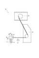
- FIG. 1 shows the configuration of a hollow fiber membrane production apparatus 10 for producing a porous hollow fiber membrane.
- the hollow fiber membrane production apparatus 10 includes a melt kneader 11 that melts and kneads a thermoplastic resin, an organic liquid, and inorganic fine powder to extrude a melt-kneaded product P, and a hollow fiber that is provided on the tip (extrusion) side of the melt kneader 11.
- a molding nozzle 12, a suction device 13 for generating cooling air for the melt-kneaded material discharged from the hollow fiber molding nozzle 12, a cooling tank 14 for cooling and solidifying the melt-kneaded part, and a solidified hollow It is comprised from the winding roller 15 which winds up a filament.
- the melt kneader 11 is a normal melt kneader, for example, a twin screw extruder.
- the melt-kneaded product P supplied from the melt-kneader 11 is discharged from the hollow fiber molding nozzle 12 and is idled while receiving cooling air from the suction machine 13.
- the melt-kneaded product is solidified through the cooling bath, and the solidified hollow fiber-like product is taken up by the take-up roller 15.
- the melt-kneaded product P supplied from the melt-kneader 11 flows through the space provided in the melt-kneader 11 and the hollow fiber molding nozzle 12 to form the hollow fiber.
- the ink is discharged from the discharge port 21 of the spinneret 20 provided in the nozzle 12.
- a hollow portion forming fluid such as air or a high boiling point liquid passes through a cylindrical through-hole provided in the central portion of the hollow fiber molding nozzle 12 and is a discharge portion for a hollow portion forming fluid different from the discharge port 21. From below.
- the spinneret 20 is a portion that molds and discharges the melt-kneaded product P that is melt-kneaded and extruded by the melt-kneader 11 and is a spinneret for forming a hollow fiber.
- the spinneret 20 has an inlet 22 for receiving the melt-kneaded product P extruded from the extrusion port 11a of the melt-kneader 11, and a discharge port 21 for molding and discharging the melt-kneaded product.
- the discharge port 21 of the spinneret 20 is a double annular discharge port.
- a porous multilayer hollow fiber membrane can be produced by providing one or more separation layers on the outer surface of the porous hollow fiber membrane of the present embodiment.
- the separation layer is a layer having a pore diameter different from the outer surface pores of the porous hollow fiber membrane.
- the separation layer can be provided on the outer surface of the porous hollow fiber membrane of the present embodiment, for example, as follows.
- a hollow fiber molding nozzle having two or more annular discharge ports arranged concentrically is attached to the tip of the extruder, and each annular discharge port
- the melt-kneaded material can be fed and extruded from different extruders.
- a hollow fiber-like extrudate having a multilayer structure can be obtained by merging and superposing melt-kneaded materials supplied from different extruders at the discharge port.
- melt-kneaded materials having different compositions from the annular discharge ports adjacent to each other it is possible to obtain multilayer films having different pore diameters of the layers adjacent to each other.
- a multilayer film may be produced by coating a separation layer having a different composition on the outer surface of the porous hollow fiber membrane.
- compositions different from each other indicate a case where the constituent materials of the melt-kneaded material are different, or a case where the constituent materials are the same but the constituent ratios are different. Even in the same kind of thermoplastic resin, if the molecular weight or molecular weight distribution is clearly different, the constituent materials are considered different.
- the hollow fiber molding nozzle 12 is provided with a plurality of (here, two) filters 26.
- the filter 26 is provided between the extrusion port of the melt kneader 11 and the discharge port 21 of the spinneret 20 in the hollow fiber molding nozzle 12, and the attachment position is melted from the extrusion port 11 a of the melt kneader 11. It is a position where the kneaded material P passes within 2000 seconds after being extruded. That is, the melt-kneaded material P extruded from the extrusion port 11a of the melt-kneader 11 passes through the filter 26 within 2000 seconds. It is preferable that the filter 26 is provided in the hollow fiber molding nozzle 12 so as to be 2 or more and 5 or less.
- the filter 26 By passing the melt-kneaded material through the filter 26, not only can a porous hollow fiber membrane having few independent pores and high communication properties, that is, high actual liquid performance be obtained, but also a porous hollow fiber membrane having high compressive strength can be obtained. Obtainable.
- a filter having a relatively large opening (slit width) in order to remove foreign substances such as insoluble matters and scorching.
- the filter 26 according to the present embodiment has a purpose for this purpose. Clearly different.
- the aggregate of inorganic fine powder in the melt-kneaded material is oriented.
- the inorganic fine powder is considered to form an aggregate in which the organic liquid becomes a binder in the melt-kneaded product, and this aggregate is a part that mainly forms pores of the obtained hollow fiber membrane.
- the aggregate of inorganic fine powder is oriented. Further, by applying a spinning draft after the melt-kneaded material is discharged from the discharge port 21 of the hollow fiber molding nozzle 12 until it enters the cooling tank 14, the aggregate of inorganic fine powder can be further oriented.
- the pores of the resulting porous hollow fiber membrane also have a more oriented structure.
- a melt-kneaded product containing a thermoplastic resin, an organic liquid and inorganic fine powder having an average primary particle size of 18 nm to 100 nm is passed through a filter having a pore size of 30 ⁇ m to 500 ⁇ m.
- a step of producing a porous hollow fiber membrane is
- the size of the draft is represented by the draft ratio, and is determined by the ratio between the linear speed when the melt-kneaded material is discharged from the hollow fiber molding nozzle 12 and the speed at which the hollow fiber-shaped material solidified by the winding roller 15 is taken up. expressed.
- the draft ratio can be changed by adjusting these.
- the draft ratio is preferably 1.5 to 20, more preferably 1.6 to 18, and still more preferably 1.7 to 15. If the draft ratio is 1.5 or more, aggregates of inorganic fine powder can be oriented. On the other hand, if the draft ratio is greater than 20, it is difficult to stably spin the hollow fiber membrane, so 20 or less is desirable.
- the thickness of the polymer trunk can be made effective for the compressive strength of the porous hollow fiber membrane, and the compressive strength of the porous hollow fiber membrane can be further increased. Become.
- the pore size of the filter is 30 ⁇ m to 500 ⁇ m, preferably 30 ⁇ m to 450 ⁇ m, and more preferably 30 ⁇ m to 390 ⁇ m. If it is 30 ⁇ m or more, it is possible to spin stably without causing ejection failure. Moreover, if it is 500 micrometers or less, since it can be set as the structure which orientated the hole as mentioned above, it can make compressive strength high.
- a commercially available sintered filter a stainless steel mesh woven with stainless steel wire, a ceramic filter, or the like can be suitably used.
- a stainless steel mesh that is highly durable at high temperatures and is easy to make a filter having fine slits is preferable.
- stainless steel wire with a thin wire diameter is used, so it is also possible to apply a filter with a large wire diameter and a large slit width from the back to double the filter, in order to avoid risks such as filter breakage. It can be used suitably.
- the shape, thickness and the like of the filter 26 are appropriately selected and are not particularly limited. That is, it may be a mesh shape, may be a honeycomb shape found in a ceramic filter, or may be a narrow flow path shape such as an orifice. In particular, a mesh shape or a honeycomb shape having a plurality of slits is preferable from the viewpoint of dispersibility, and a thin mesh filter with little pressure loss is most preferable.
- FIG. 2 is a diagram illustrating an example of the configuration of the filter 26.
- FIG. 2 schematically shows a case where the filter 26 has a mesh shape, and has a predetermined slit width d.
- the slit width d corresponds to the filter pore diameter, and is 30 ⁇ m to 500 ⁇ m, preferably 30 ⁇ m to 450 ⁇ m, and more preferably 30 ⁇ m to 390 ⁇ m.
- extraction and removal of organic liquid and inorganic fine powder will be described.
- the extraction and removal of the organic liquid and the inorganic fine powder can be performed simultaneously as long as they can be extracted and removed with the same solvent, but usually the extraction and removal are performed separately.
- the extraction and removal of the organic liquid can be performed by using an extraction liquid that is miscible with the organic liquid without dissolving or modifying the kneaded thermoplastic resin and contacting the extraction liquid by a technique such as immersion. it can.
- the extraction liquid is conveniently volatile so that it can be easily removed from the hollow fiber membrane after extraction. Examples of the extraction liquid include alcohols and methylene chloride. If the organic liquid is water-soluble, water can be used as the extraction liquid.
- the inorganic fine powder when the inorganic fine powder is silica, the inorganic fine powder can be extracted and removed by first contacting with an alkaline solution to convert the silica to silicate, and then contacting with water to extract and remove the silicate. it can.
- Either extraction or removal of organic liquid or inorganic fine powder can be performed first.
- both of them organic liquid and inorganic fine powder
- the organic liquid is first extracted and removed.
- the extraction and removal of the inorganic fine powder is advantageous because the inorganic fine powder can be smoothly extracted and removed using the aqueous extraction liquid.
- the porous hollow fiber membrane can be obtained by extracting and removing the organic liquid and the inorganic fine powder from the cooled and solidified hollow fiber-like material.
- the hollow fiber-like material after cooling and solidification, (1) before extraction and removal of organic liquid and inorganic fine powder, (2) after extraction removal of organic liquid and before extraction removal of inorganic fine powder, (3) extraction and removal of inorganic fine powder Before the extraction and removal of the organic liquid, and (4) after the extraction and removal of the organic liquid and inorganic fine powder, the hollow fiber-like material may be stretched in the longitudinal direction within a range of 3 times or less. it can.
- the porous hollow fiber membrane is stretched in the longitudinal direction, the water permeability is improved, but the pressure resistance (rupture strength and compressive strength) is lowered, so that the membrane does not often have a practical strength after stretching.
- the porous hollow fiber membrane 1 is a machine. High strength. Therefore, it can be carried out as long as the stretching is performed at a low magnification within 3 times. By this stretching, the water permeability of the porous hollow fiber membrane can be improved.
- the draw ratio said here shows the value which divided the hollow fiber length after extending
- the stretched film may be subjected to heat treatment to increase the pressure resistance.
- the heat treatment temperature is usually suitably carried out below the melting point of the thermoplastic resin.
- the aspect ratio of the outer surface hole and inner surface hole of the porous hollow fiber membrane can be controlled as follows. (1) When the pore size of the filter is reduced, the inorganic fine powder aggregates are oriented, the aspect ratio of the pores is increased, and the linear velocity when the inorganic fine powder aggregates pass through the filter is increased. Aggregates of fine powder are more easily oriented. Moreover, it is easy to orient the aggregates of inorganic fine powders by applying a draft, and it becomes easier to orient by increasing the draft ratio. (2) When the particle size of the inorganic fine powder is increased, the aggregate of the inorganic fine powder is easily oriented when passing through the filter.
- the aspect ratio of the outer surface hole and the inner surface hole of the porous hollow fiber membrane can be controlled by appropriately adjusting the inner diameter and outer diameter of the hollow fiber molding nozzle 12.
- the present embodiment will be described more specifically with reference to examples and comparative examples. However, the present embodiment is not limited only to these examples.
- the measuring method used for this Embodiment is as follows. The following measurements are all performed at 25 ° C. unless otherwise specified. Below, after explaining an evaluation method, the manufacturing method and evaluation result of an Example and a comparative example are explained.
- the pressurized pressure exceeds the compressive strength of the hollow fiber membrane, the hollow part is crushed. Since the clogging starts, the absolute value of the permeated water amount decreases even though the pressurizing pressure increases.
- the pressurizing pressure at which the absolute value of the amount of permeated water was maximized was defined as the compressive strength.
- the raw materials used in the examples are shown below.
- Example 1 Vinylidene fluoride homopolymer as the thermoplastic resin, a mixture of bis (2-ethylhexyl) phthalate and dibutyl phthalate as the organic liquid, finely divided silica as inorganic fine powder (manufactured by Nippon Aerosil Co., Ltd., trade name: Nax50, average primary particle)
- the hollow fiber membrane was melt extruded using a melt kneader using a spinneret having a diameter of about 30 nm and a double annular discharge port.
- the outer diameter of the nozzle refers to the outermost diameter of the discharge port
- the inner diameter of the nozzle refers to the maximum diameter of the partition wall between the melt-kneaded product discharge port and the hollow portion forming fluid discharge port.
- the filter used was a laminate of one 150 mesh (plain weave, slit width 109 ⁇ m: manufactured by Taiyo Wire Mesh Co., Ltd.) and one 40 mesh (plain weave, slit width 390 ⁇ m: manufactured by Taiyo Wire Mesh Co., Ltd.). .
- the resulting hollow fiber melt-kneaded product was extracted with methylene chloride to remove phthalic acid (2-ethylhexyl) and dibutyl phthalate and then dried. Then, it was immersed in 40 mass% ethanol aqueous solution for 30 minutes, and was immersed in water for 30 minutes. Next, it was immersed in a 5% by mass aqueous sodium hydroxide solution for 100 minutes, and further washed with water to extract and remove finely divided silica.
- Example 2 A hollow fiber membrane was obtained in the same manner as in Example 1 except that the inorganic fine powder was changed to trade name: RX50 (average primary particle size: about 40 nm) manufactured by Nippon Aerosil Co., Ltd.
- Example 3 A hollow fiber membrane was obtained in the same manner as in Example 1 except that the inorganic fine powder was changed to trade name: NX90G (average primary particle size: about 20 nm) manufactured by Nippon Aerosil Co., Ltd.
- Example 4 A hollow fiber membrane was obtained in the same manner as in Example 1 except that only 40 mesh (plain weave, slit width 390 ⁇ m: manufactured by Taiyo Wire Mesh Co., Ltd.) was used as the filter.
- Example 5 The filter was changed to a stack of one 400 mesh (plain weave, slit width 34 ⁇ m: manufactured by Taiyo Wire Mesh Co., Ltd.) and one 40 mesh (plain weave, slit width 390 ⁇ m: manufactured by Taiyo Wire Mesh Co., Ltd.). Except for the above, a hollow fiber membrane was obtained in the same manner as in Example 1.
- Example 6 Except for changing the inorganic fine powder to Nippon Aerosil Co., Ltd. trade name: NX90G (average primary particle size: about 20 nm) and using only 40 mesh (plain weave, slit width 390 ⁇ m: Taiyo Wire Mesh Co., Ltd.) as a filter. A hollow fiber membrane was obtained in the same manner as in Example 1.
- Example 9 A hollow fiber membrane was obtained in the same manner as in Example 1 except that the draft ratio was changed to 15.
- Example 10 A hollow fiber membrane was obtained in the same manner as in Example 1 except that the draft ratio was changed to 1.7.
- Example 11 A hollow fiber membrane was obtained in the same manner as in Example 1 except that the inorganic fine powder was changed to Tosoh Silica Co., Ltd. trade name: NipSeal E74P (average primary particle size: about 74 nm).
- Example 1 A hollow fiber membrane was obtained in the same manner as in Example 1 except that the inorganic fine powder was changed to Nippon Aerosil Co., Ltd. trade name: R972 (average primary particle size: about 16 nm).
- the hollow fiber membrane did not have a structure in which the pores were oriented, and the polymer trunk was thin, so that the compression strength could not be increased.
- Example 2 A hollow fiber membrane was obtained in the same manner as in Example 1 except that only 30 mesh (plain weave, slit width 560 ⁇ m: manufactured by Taiyo Wire Mesh Co., Ltd.) was used as a filter.
- the hollow fiber membrane did not have a structure in which the pores were oriented, and the polymer trunk was thin, so that the compression strength could not be increased.
- Example 3 The filter was changed to a stack of 1 sheet of 635 mesh (twill weave, slit width 20 ⁇ m: manufactured by Taiyo Wire Mesh Co., Ltd.) and 1 sheet of 40 mesh (plain weave, slit width 390 ⁇ m: manufactured by Taiyo Wire Mesh Co., Ltd.). Except for the above, a hollow fiber membrane was obtained in the same manner as in Example 1. The hollow fiber membrane had a structure in which the outer surface pores were oriented, and high compressive strength was obtained. However, since the polymer trunk was thick, the pure water permeability was small. In addition, since the slit width (hole diameter) of the filter used was small, ejection failure occurred in a short time and spinning became impossible.
- Example 4 The filter was changed to a stack of one 500 mesh (twill weave, slit width 26 ⁇ m: manufactured by Taiyo Wire Mesh Co., Ltd.) and one 40 mesh (plain weave, slit width 390 ⁇ m: manufactured by Taiyo Wire Mesh Co., Ltd.). Except for the above, a hollow fiber membrane was obtained in the same manner as in Example 1. The hollow fiber membrane had a structure in which the outer surface pores were oriented and high compressive strength was obtained, but the pure water permeability was small because the orientation of the inner surface pores was large. In addition, since the slit width (hole diameter) of the filter used was small, ejection failure occurred in a short time and spinning became impossible.
- Table 1 shows the physical properties of the hollow fiber membranes produced in Examples and Comparative Examples.
- SYMBOLS 10 Hollow fiber membrane manufacturing apparatus, 11 ... Melt kneader, 11a ... Extrusion port, 12 ... Nozzle for hollow fiber molding, 13 ... Suction machine, 14 ... Cooling tank, 15 ... Winding roller, 20 ... Spinneret, 21 ... Discharge port, 22 ... inlet, 26 ... filter, d ... slit width, P ... melt-kneaded material.
Abstract
Description
(2)純水透水率が9000L/m2/hr以上であって、耐圧縮強度が0.8MPa以上である、(1)記載の多孔性中空糸膜。
(3)(1)又は(2)に記載の多孔性中空糸膜の外表面上に、1層以上の分離層を有する、多孔性多層中空糸膜。
(4)熱可塑性樹脂、有機液体及び平均一次粒径18nm~100nmの無機微粉を含む溶融混練物を、孔径30μm~500μmのフィルターを通した後に、円環状吐出口を有する紡糸口金から吐出して中空糸状溶融混練物を成形する工程と、中空糸状溶融混練物を冷却固化した後、有機液体及び無機微粉を抽出除去して多孔性中空糸膜を作製する工程と、を備える多孔性中空糸膜の製造方法。
(5)上記無機微粉がシリカである、(4)記載の多孔性中空糸膜の製造方法。 (1) It contains a thermoplastic resin, the outer surface hole has an aspect ratio of 10 or more, the inner surface hole has an aspect ratio of 1 to 5, and the polymer trunk forming the outer surface hole has a thickness of 1 μm to 20 μm. A porous hollow fiber membrane.
(2) The porous hollow fiber membrane according to (1), having a pure water permeability of 9000 L / m 2 / hr or more and a compressive strength of 0.8 MPa or more.
(3) A porous multilayer hollow fiber membrane having one or more separation layers on the outer surface of the porous hollow fiber membrane according to (1) or (2).
(4) A melt-kneaded product containing a thermoplastic resin, an organic liquid, and inorganic fine powder having an average primary particle size of 18 nm to 100 nm is passed through a filter with a pore size of 30 μm to 500 μm, and then discharged from a spinneret having an annular discharge port. A porous hollow fiber membrane comprising: a step of forming a hollow fiber melt-kneaded product; and a step of cooling and solidifying the hollow fiber melt-kneaded product and then extracting and removing organic liquid and inorganic fine powder to produce a porous hollow fiber membrane. Manufacturing method.
(5) The method for producing a porous hollow fiber membrane according to (4), wherein the inorganic fine powder is silica.
本実施形態の多孔性中空糸膜は、熱可塑性樹脂を含有し、外表面孔のアスペクト比が10以上であり、内表面孔のアスペクト比が1~5であり、外表面孔を形成するポリマーの幹の太さが1μm~20μmであることを特徴とする。 [Porous hollow fiber membrane]
The porous hollow fiber membrane of this embodiment contains a thermoplastic resin, the outer surface hole has an aspect ratio of 10 or more, the inner surface hole has an aspect ratio of 1 to 5, and is a polymer trunk that forms the outer surface hole. Is characterized by having a thickness of 1 μm to 20 μm.
外表面孔のアスペクト比=(外表面孔における長径)/(外表面孔における短径) The aspect ratio of the outer surface hole is a value obtained by dividing the major axis of the outer surface hole by the minor axis of the outer surface hole, as shown in the following formula.
Aspect ratio of outer surface hole = (major axis in outer surface hole) / (minor diameter in outer surface hole)
内表面孔のアスペクト比=(内表面孔における長径)/(内表面孔における短径) The aspect ratio of the inner surface hole is a value obtained by dividing the major axis of the inner surface hole by the minor axis of the inner surface hole, as shown in the following formula. The measuring method is the same as that for measuring the outer surface hole.
Aspect ratio of inner surface hole = (major axis in inner surface hole) / (minor diameter in inner surface hole)
本実施形態の多孔性中空糸膜の製造方法は、熱可塑性樹脂、有機液体及び平均一次粒径18nm~100nmの無機微粉を含む溶融混練物を、孔径30μm~500μmのフィルターを通した後に、円環状吐出口を有する紡糸口金から吐出して中空糸状溶融混練物を成形する工程と、中空糸状溶融混練物を冷却固化した後、有機液体及び無機微粉を抽出除去して多孔性中空糸膜を作製する工程と、を備えることを特徴とする。 [Method for producing porous hollow fiber membrane]
The method for producing the porous hollow fiber membrane of the present embodiment is obtained by passing a melt-kneaded product containing a thermoplastic resin, an organic liquid and inorganic fine powder having an average primary particle size of 18 nm to 100 nm through a filter having a pore size of 30 μm to 500 μm, A process for forming a hollow fiber-like melt-kneaded product by discharging from a spinneret having an annular discharge port, and cooling and solidifying the hollow fiber-like melt-kneaded material, and then extracting and removing organic liquid and inorganic fine powder to produce a porous hollow fiber membrane And a step of performing.
また、本実施形態の多孔性中空糸膜を形成した後に、多孔性中空糸膜の外表面上に異なる組成の分離層をコーティングして、多層膜を作製してもよい。 When producing a porous multilayer hollow fiber membrane, a hollow fiber molding nozzle having two or more annular discharge ports arranged concentrically is attached to the tip of the extruder, and each annular discharge port The melt-kneaded material can be fed and extruded from different extruders. A hollow fiber-like extrudate having a multilayer structure can be obtained by merging and superposing melt-kneaded materials supplied from different extruders at the discharge port. At this time, by extruding melt-kneaded materials having different compositions from the annular discharge ports adjacent to each other, it is possible to obtain multilayer films having different pore diameters of the layers adjacent to each other.
Moreover, after forming the porous hollow fiber membrane of the present embodiment, a multilayer film may be produced by coating a separation layer having a different composition on the outer surface of the porous hollow fiber membrane.
(1)フィルターの孔径を小さくすると、無機微粉の凝集体が配向して、孔のアスペクト比が大きくなり、かつ、フィルターを無機微粉の凝集体が通過する際の線速が大きくなるため、無機微粉の凝集体がより配向されやすくなる。また、ドラフトをかけることによっても、無機微粉の凝集体を配向させやすく、ドラフト比を大きくすることによっても、より配向されやすくなる。
(2)無機微粉の粒径を大きくすると、フィルターを通過する際に無機微粉の凝集体が配向されやすくなる。それは、無機微粉の1次粒径が大きくなると、凝集径も大きくなるため、フィルターを通過する際に、無機微粉の凝集体がより配向されやすくなるためである。その結果、無機微粉を抽出することができる中空糸膜の孔のアスペクト比が大きくなる。 The aspect ratio of the outer surface hole and inner surface hole of the porous hollow fiber membrane can be controlled as follows.
(1) When the pore size of the filter is reduced, the inorganic fine powder aggregates are oriented, the aspect ratio of the pores is increased, and the linear velocity when the inorganic fine powder aggregates pass through the filter is increased. Aggregates of fine powder are more easily oriented. Moreover, it is easy to orient the aggregates of inorganic fine powders by applying a draft, and it becomes easier to orient by increasing the draft ratio.
(2) When the particle size of the inorganic fine powder is increased, the aggregate of the inorganic fine powder is easily oriented when passing through the filter. This is because when the primary particle size of the inorganic fine powder is increased, the aggregate diameter is also increased, so that the aggregate of the inorganic fine powder is more easily oriented when passing through the filter. As a result, the aspect ratio of the pores of the hollow fiber membrane from which inorganic fine powder can be extracted increases.
中空糸膜を膜長手方向に垂直な向きにカミソリなどで薄く切り、顕微鏡を用いて断面の内径の長径と短径、外径の長径と短径を測定し、以下の式(2)、(3)により、それぞれ内径と外径を決定した。
中空糸膜を50質量%のエタノール水溶液中に30分間浸漬させた後、水中に30分間浸漬し、中空糸膜を湿潤化した。約10cm長の湿潤中空糸膜の一端を封止し、他端の中空部内へ注射針を入れ、注射針から0.1MPaの圧力にて25℃の純水を中空部内へ注入し、外表面へと透過してくる純水の透過水量を測定し、以下の式により純水透過流束を決定した。ここに膜有効長とは、注射針が挿入されている部分を除いた、正味の膜長を指す。

The hollow fiber membrane was immersed in a 50% by mass ethanol aqueous solution for 30 minutes and then immersed in water for 30 minutes to wet the hollow fiber membrane. Seal one end of a wet hollow fiber membrane of about 10 cm length, put an injection needle into the hollow part at the other end, and inject pure water at 25 ° C. into the hollow part at a pressure of 0.1 MPa from the injection needle. The amount of permeated water permeated into the water was measured, and the pure water permeation flux was determined by the following equation. Here, the effective membrane length refers to the net membrane length excluding the portion where the injection needle is inserted.
約5cm長の湿潤中空糸膜の一端を封止し、他端を大気開放とし、外表面より40℃の純水を加圧し大気開放端より透過水を出した。このとき膜供給水を循環させることなくその全量を濾過する方式、即ち全量濾過方式を取った。加圧圧力を0.1MPaより0.01MPa刻みで昇圧し、各圧力にて15秒間圧力を保持し、この15秒間に大気開放端より出てくる透過水をサンプリングした。中空糸膜の中空部がつぶれないうちは加圧圧力が増すにつれて透過水量(質量)の絶対値も増してゆくが、加圧圧力が中空糸膜の耐圧縮強度を超えると中空部が潰れて閉塞が始まるため、透過水量の絶対値は加圧圧力が増すにも関わらず、低下する。透過水量の絶対値が極大になる加圧圧力を耐圧縮強度とした。 (3) Compressive strength (MPa)
One end of a wet hollow fiber membrane having a length of about 5 cm was sealed, the other end was opened to the atmosphere, pure water at 40 ° C. was pressurized from the outer surface, and permeate was discharged from the open end of the atmosphere. At this time, the whole amount was filtered without circulating the membrane feed water, that is, the whole amount filtration method was adopted. The pressurization pressure was increased from 0.1 MPa in increments of 0.01 MPa, the pressure was maintained at each pressure for 15 seconds, and the permeated water coming out from the open end of the atmosphere was sampled during the 15 seconds. While the hollow part of the hollow fiber membrane is not crushed, the absolute value of the permeated water amount (mass) also increases as the pressurized pressure increases. However, when the pressurized pressure exceeds the compressive strength of the hollow fiber membrane, the hollow part is crushed. Since the clogging starts, the absolute value of the permeated water amount decreases even though the pressurizing pressure increases. The pressurizing pressure at which the absolute value of the amount of permeated water was maximized was defined as the compressive strength.
(2)純水透水率の測定で作製した湿潤中空糸膜を用い、引張り、破断時の荷重と変位を以下の条件で測定した。
測定機器:インストロン型引張試験機(島津製作所製、商品名:AGS-5D)
チャック間距離:5cm
引張り速度:20cm/分
測定温度:25℃ (4) Breaking strength (MPa), elongation at break (%)
(2) Using the wet hollow fiber membrane prepared by measuring the water permeability of pure water, the load and displacement at the time of pulling and breaking were measured under the following conditions.
Measuring instrument: Instron type tensile tester (manufactured by Shimadzu Corporation, trade name: AGS-5D)
Distance between chucks: 5cm
Tensile speed: 20 cm / min Measurement temperature: 25 ° C

実施例で用いた原材料を下記に示す。
<熱可塑性樹脂>
フッ化ビニリデンホモポリマー(株式会社クレハ製、商品名:KF#1000)
<有機液体>
フタル酸ビス(2-エチルヘキシル)(シージーエスター株式会社製)
フタル酸ジブチル(シージーエスター株式会社製)
<無機微粉>
微粉シリカ(日本アエロジル株式会社製) [raw materials]
The raw materials used in the examples are shown below.
<Thermoplastic resin>
Vinylidene fluoride homopolymer (manufactured by Kureha Co., Ltd., trade name: KF # 1000)
<Organic liquid>
Bis (2-ethylhexyl) phthalate (manufactured by CG Esther)
Dibutyl phthalate (manufactured by CG Ester Co., Ltd.)
<Inorganic fine powder>
Fine silica (manufactured by Nippon Aerosil Co., Ltd.)
熱可塑性樹脂としてフッ化ビニリデンホモポリマー、有機液体としてフタル酸ビス(2-エチルヘキシル)とフタル酸ジブチルとの混合物、無機微粉としての微粉シリカ(日本アエロジル株式会社製、商品名:Nax50、平均一次粒径:約30nm)を用い、二重円環状の吐出口を有する紡糸口金を用い、溶融混練機を用いて中空糸膜の溶融押出を行った。溶融混練物の組成はフッ化ビニリデンホモポリマー:フタル酸(2-エチルヘキシル):フタル酸ジブチル:微粉シリカ=40:30.8:6.2:23(質量比)とし、中空部形成用流体として空気を用い、外径2.00mm、内径0.92mmの中空糸形成用ノズルを用いて、240℃の樹脂温度にて中空糸状溶融混練物を得た。ここで、ノズルの外径とは、吐出口の最外径を指し、ノズルの内径とは、溶融混練物吐出口と中空部形成用流体吐出口との間の隔壁の最大径を指す。押出した中空糸状押出物は、ドラフト比2.8で35cmの空中走行を経た後40℃の水浴中に導き入れることで冷却固化させ、35m/分の速度でかせに巻き取った。フィルターは、150メッシュ(平織、スリット幅109μm:太陽金網株式会社製)1枚と、そのバックアップとしての40メッシュ(平織、スリット幅390μm:太陽金網株式会社製)1枚を重ねたものを用いた。 (Example 1)
Vinylidene fluoride homopolymer as the thermoplastic resin, a mixture of bis (2-ethylhexyl) phthalate and dibutyl phthalate as the organic liquid, finely divided silica as inorganic fine powder (manufactured by Nippon Aerosil Co., Ltd., trade name: Nax50, average primary particle) The hollow fiber membrane was melt extruded using a melt kneader using a spinneret having a diameter of about 30 nm and a double annular discharge port. The composition of the melt-kneaded product was vinylidene fluoride homopolymer: phthalic acid (2-ethylhexyl): dibutyl phthalate: fine powder silica = 40: 30.8: 6.2: 23 (mass ratio) as a fluid for forming a hollow part Using air, a hollow fiber melt-kneaded product was obtained at a resin temperature of 240 ° C. using a hollow fiber forming nozzle having an outer diameter of 2.00 mm and an inner diameter of 0.92 mm. Here, the outer diameter of the nozzle refers to the outermost diameter of the discharge port, and the inner diameter of the nozzle refers to the maximum diameter of the partition wall between the melt-kneaded product discharge port and the hollow portion forming fluid discharge port. The extruded hollow fiber-shaped extrudate was cooled and solidified by being introduced into a 40 ° C. water bath after passing through the air of 35 cm in a draft ratio of 2.8, and wound up skein at a speed of 35 m / min. The filter used was a laminate of one 150 mesh (plain weave, slit width 109 μm: manufactured by Taiyo Wire Mesh Co., Ltd.) and one 40 mesh (plain weave, slit width 390 μm: manufactured by Taiyo Wire Mesh Co., Ltd.). .
無機微粉を日本アエロジル株式会社製の商品名:RX50(平均一次粒径:約40nm)に変更した以外は、実施例1と同様の方法で中空糸膜を得た。 (Example 2)
A hollow fiber membrane was obtained in the same manner as in Example 1 except that the inorganic fine powder was changed to trade name: RX50 (average primary particle size: about 40 nm) manufactured by Nippon Aerosil Co., Ltd.
無機微粉を日本アエロジル株式会社製の商品名:NX90G(平均一次粒径:約20nm)に変更した以外は、実施例1と同様の方法で中空糸膜を得た。 (Example 3)
A hollow fiber membrane was obtained in the same manner as in Example 1 except that the inorganic fine powder was changed to trade name: NX90G (average primary particle size: about 20 nm) manufactured by Nippon Aerosil Co., Ltd.
フィルターとして、40メッシュ(平織、スリット幅390μm:太陽金網株式会社製)のみを用いた以外は、実施例1と同様の方法で中空糸膜を得た。 Example 4
A hollow fiber membrane was obtained in the same manner as in Example 1 except that only 40 mesh (plain weave, slit width 390 μm: manufactured by Taiyo Wire Mesh Co., Ltd.) was used as the filter.
フィルターを、400メッシュ(平織、スリット幅34μm:太陽金網株式会社製)1枚と、そのバックアップとしての40メッシュ(平織、スリット幅390μm:太陽金網株式会社製)1枚を重ねたものに変更した以外は、実施例1と同様の方法で中空糸膜を得た。 (Example 5)
The filter was changed to a stack of one 400 mesh (plain weave, slit width 34 μm: manufactured by Taiyo Wire Mesh Co., Ltd.) and one 40 mesh (plain weave, slit width 390 μm: manufactured by Taiyo Wire Mesh Co., Ltd.). Except for the above, a hollow fiber membrane was obtained in the same manner as in Example 1.
無機微粉を日本アエロジル株式会社製の商品名:NX90G(平均一次粒径:約20nm)に変更し、フィルターとして、40メッシュ(平織、スリット幅390μm:太陽金網株式会社製)のみを用いた以外は、実施例1と同様の方法で中空糸膜を得た。 (Example 6)
Except for changing the inorganic fine powder to Nippon Aerosil Co., Ltd. trade name: NX90G (average primary particle size: about 20 nm) and using only 40 mesh (plain weave, slit width 390 μm: Taiyo Wire Mesh Co., Ltd.) as a filter. A hollow fiber membrane was obtained in the same manner as in Example 1.
溶融混練物の組成をフッ化ビニリデンホモポリマー:フタル酸(2-エチルヘキシル):フタル酸ジブチル:微粉シリカ=30:35.9:7.2:26.9(質量比)に変更した以外は、実施例1と同様の方法で中空糸膜を得た。 (Example 7)
Except for changing the composition of the melt-kneaded product to vinylidene fluoride homopolymer: phthalic acid (2-ethylhexyl): dibutyl phthalate: finely divided silica = 30: 35.9: 7.2: 26.9 (mass ratio) A hollow fiber membrane was obtained in the same manner as in Example 1.
溶融混練物の組成をフッ化ビニリデンホモポリマー:フタル酸(2-エチルヘキシル):フタル酸ジブチル:微粉シリカ=45:28.2:5.6:21.2(質量比)に変更した以外は、実施例1と同様の方法で中空糸膜を得た。 (Example 8)
Except that the composition of the melt-kneaded product was changed to vinylidene fluoride homopolymer: phthalic acid (2-ethylhexyl): dibutyl phthalate: finely divided silica = 45: 28.2: 5.6: 21.2 (mass ratio) A hollow fiber membrane was obtained in the same manner as in Example 1.
ドラフト比を15に変更した以外は、実施例1と同様の方法で中空糸膜を得た。 Example 9
A hollow fiber membrane was obtained in the same manner as in Example 1 except that the draft ratio was changed to 15.
ドラフト比を1.7に変更した以外は、実施例1と同様の方法で中空糸膜を得た。 (Example 10)
A hollow fiber membrane was obtained in the same manner as in Example 1 except that the draft ratio was changed to 1.7.
無機微粉を東ソー・シリカ株式会社製の商品名:ニップシールE74P(平均一次粒径:約74nm)に変更した以外は、実施例1と同様の方法で中空糸膜を得た。 (Example 11)
A hollow fiber membrane was obtained in the same manner as in Example 1 except that the inorganic fine powder was changed to Tosoh Silica Co., Ltd. trade name: NipSeal E74P (average primary particle size: about 74 nm).
無機微粉を日本アエロジル株式会社製の商品名:R972(平均一次粒径:約16nm)に変更した以外は、実施例1と同様の方法で中空糸膜を得た。該中空糸膜は、孔が配向した構造にならず、ポリマーの幹も細いため、耐圧縮強度を高くすることができなかった。 (Comparative Example 1)
A hollow fiber membrane was obtained in the same manner as in Example 1 except that the inorganic fine powder was changed to Nippon Aerosil Co., Ltd. trade name: R972 (average primary particle size: about 16 nm). The hollow fiber membrane did not have a structure in which the pores were oriented, and the polymer trunk was thin, so that the compression strength could not be increased.
フィルターとして、30メッシュ(平織、スリット幅560μm:太陽金網株式会社製)のみに用いた以外は、実施例1と同様の方法で中空糸膜を得た。該中空糸膜は、孔が配向した構造にならず、ポリマーの幹も細いため、耐圧縮強度を高くすることができなかった。 (Comparative Example 2)
A hollow fiber membrane was obtained in the same manner as in Example 1 except that only 30 mesh (plain weave, slit width 560 μm: manufactured by Taiyo Wire Mesh Co., Ltd.) was used as a filter. The hollow fiber membrane did not have a structure in which the pores were oriented, and the polymer trunk was thin, so that the compression strength could not be increased.
フィルターを、635メッシュ(綾織、スリット幅20μm:太陽金網株式会社製)1枚と、そのバックアップとしての40メッシュ(平織、スリット幅390μm:太陽金網株式会社製)1枚を重ねたものに変更した以外は、実施例1と同様の方法で中空糸膜を得た。該中空糸膜は、外表面孔が配向した構造になり、高い圧縮強度は得られたが、ポリマーの幹が太いため、純水透水率が小さくなった。また、用いたフィルターのスリット幅(孔径)が小さいため、短時間で吐出不良を起こし、紡糸不可となった。 (Comparative Example 3)
The filter was changed to a stack of 1 sheet of 635 mesh (twill weave, slit
フィルターを、500メッシュ(綾織、スリット幅26μm:太陽金網株式会社製)1枚と、そのバックアップとしての40メッシュ(平織、スリット幅390μm:太陽金網株式会社製)1枚を重ねたものに変更した以外は、実施例1と同様の方法で中空糸膜を得た。該中空糸膜は、外表面孔が配向した構造になり、高い圧縮強度は得られたが、内表面孔の配向が大きいため、純水透水率が小さくなった。また、用いたフィルターのスリット幅(孔径)が小さいため、短時間で吐出不良を起こし、紡糸不可となった。 (Comparative Example 4)
The filter was changed to a stack of one 500 mesh (twill weave, slit

Claims (5)
- 熱可塑性樹脂を含有し、外表面孔のアスペクト比が10以上であり、内表面孔のアスペクト比が1~5であり、前記外表面孔を形成するポリマーの幹の太さが1μm~20μmである、多孔性中空糸膜。 A thermoplastic resin, the outer surface hole has an aspect ratio of 10 or more, the inner surface hole has an aspect ratio of 1 to 5, and the thickness of the polymer trunk forming the outer surface hole is 1 μm to 20 μm; Porous hollow fiber membrane.
- 純水透水率が9000L/m2/hr以上であり、耐圧縮強度が0.8MPa以上である、請求項1記載の多孔性中空糸膜。 The porous hollow fiber membrane according to claim 1, having a pure water permeability of 9000 L / m 2 / hr or more and a compressive strength of 0.8 MPa or more.
- 請求項1又は2に記載の多孔性中空糸膜の外表面上に、1層以上の分離層を有する、多孔性多層中空糸膜。 A porous multilayer hollow fiber membrane having one or more separation layers on the outer surface of the porous hollow fiber membrane according to claim 1 or 2.
- 熱可塑性樹脂、有機液体及び平均一次粒径18nm~100nmである無機微粉を含む溶融混練物を、孔径30μm~500μmのフィルターを通した後に、円環状吐出口を有する紡糸口金から吐出して中空糸状溶融混練物を成形する工程と、
前記中空糸状溶融混練物を冷却固化した後、前記有機液体及び前記無機微粉を抽出除去して多孔性中空糸膜を作製する工程と、
を備える多孔性中空糸膜の製造方法。 A melt-kneaded product containing a thermoplastic resin, an organic liquid, and inorganic fine powder having an average primary particle size of 18 nm to 100 nm is passed through a filter having a pore size of 30 μm to 500 μm, and then discharged from a spinneret having an annular discharge port to form a hollow fiber. Forming a melt-kneaded product;
After cooling and solidifying the hollow fiber-like melt-kneaded product, a step of extracting and removing the organic liquid and the inorganic fine powder to produce a porous hollow fiber membrane;
A method for producing a porous hollow fiber membrane comprising: - 前記無機微粉がシリカである、請求項4記載の多孔性中空糸膜の製造方法。 The method for producing a porous hollow fiber membrane according to claim 4, wherein the inorganic fine powder is silica.
Priority Applications (3)
| Application Number | Priority Date | Filing Date | Title |
|---|---|---|---|
| JP2015506793A JP6097818B2 (en) | 2013-03-21 | 2014-03-18 | Porous hollow fiber membrane and method for producing porous hollow fiber membrane |
| CN201480006957.5A CN104968422B (en) | 2013-03-21 | 2014-03-18 | The manufacturing method of porous hollow fibres film and porous hollow fibres film |
| US14/776,943 US10023709B2 (en) | 2013-03-21 | 2014-03-18 | Multiporous hollow-fiber membrane and process for producing multiporous hollow-fiber membrane |
Applications Claiming Priority (2)
| Application Number | Priority Date | Filing Date | Title |
|---|---|---|---|
| JP2013-058333 | 2013-03-21 | ||
| JP2013058333 | 2013-03-21 |
Publications (1)
| Publication Number | Publication Date |
|---|---|
| WO2014148470A1 true WO2014148470A1 (en) | 2014-09-25 |
Family
ID=51580148
Family Applications (1)
| Application Number | Title | Priority Date | Filing Date |
|---|---|---|---|
| PCT/JP2014/057276 WO2014148470A1 (en) | 2013-03-21 | 2014-03-18 | Multiporous hollow-fiber membrane and process for producing multiporous hollow-fiber membrane |
Country Status (4)
| Country | Link |
|---|---|
| US (1) | US10023709B2 (en) |
| JP (1) | JP6097818B2 (en) |
| CN (1) | CN104968422B (en) |
| WO (1) | WO2014148470A1 (en) |
Cited By (1)
| Publication number | Priority date | Publication date | Assignee | Title |
|---|---|---|---|---|
| JPWO2018088232A1 (en) * | 2016-11-09 | 2019-06-24 | 旭化成株式会社 | Porous hollow fiber membrane and method for producing porous hollow fiber membrane |
Families Citing this family (2)
| Publication number | Priority date | Publication date | Assignee | Title |
|---|---|---|---|---|
| CN106669444A (en) * | 2015-11-11 | 2017-05-17 | 重庆润泽医药有限公司 | Polytetrafluoroethylene fiber membrane |
| KR101966203B1 (en) * | 2017-09-08 | 2019-04-05 | (주)디유티코리아 | Manufacturing method of foam mattress with multi-hardness & multi-elasticity by continuous foaming process |
Citations (6)
| Publication number | Priority date | Publication date | Assignee | Title |
|---|---|---|---|---|
| JPH0342025A (en) * | 1989-07-10 | 1991-02-22 | Asahi Chem Ind Co Ltd | Production of polyolefin porous film |
| JPH04180824A (en) * | 1990-11-13 | 1992-06-29 | Daicel Chem Ind Ltd | Porous hollow yarn membrane |
| WO2007043553A1 (en) * | 2005-10-13 | 2007-04-19 | Asahi Kasei Chemicals Corporation | Porous multilayered hollow-fiber membrane and process for producing the same |
| JP2009219979A (en) * | 2008-03-14 | 2009-10-01 | Asahi Kasei Chemicals Corp | Porous multilayer hollow fiber membrane |
| WO2010029908A1 (en) * | 2008-09-10 | 2010-03-18 | 東レ株式会社 | Hollow-fiber membrane and process for production of hollow-fiber membrane |
| JP2012040461A (en) * | 2010-08-13 | 2012-03-01 | Asahi Kasei Chemicals Corp | Method for manufacturing porous hollow fiber membrane, porous hollow fiber membrane, module using porous hollow fiber membrane, filter using porous hollow fiber membrane, and water-treating method using porous hollow fiber membrane |
Family Cites Families (3)
| Publication number | Priority date | Publication date | Assignee | Title |
|---|---|---|---|---|
| US4530809A (en) | 1980-10-14 | 1985-07-23 | Mitsubishi Rayon Co., Ltd. | Process for making microporous polyethylene hollow fibers |
| JPS5766114A (en) | 1980-10-14 | 1982-04-22 | Mitsubishi Rayon Co Ltd | Porous polyethylene hollow fiber and its production |
| CN102219969B (en) * | 2010-04-13 | 2013-06-19 | 广州美能材料科技有限公司 | Polyvinylidene fluoride-polyether sulfone blended hollow fiber membrane and thermally induced phase separation preparation method |
-
2014
- 2014-03-18 JP JP2015506793A patent/JP6097818B2/en active Active
- 2014-03-18 US US14/776,943 patent/US10023709B2/en active Active
- 2014-03-18 WO PCT/JP2014/057276 patent/WO2014148470A1/en active Application Filing
- 2014-03-18 CN CN201480006957.5A patent/CN104968422B/en active Active
Patent Citations (6)
| Publication number | Priority date | Publication date | Assignee | Title |
|---|---|---|---|---|
| JPH0342025A (en) * | 1989-07-10 | 1991-02-22 | Asahi Chem Ind Co Ltd | Production of polyolefin porous film |
| JPH04180824A (en) * | 1990-11-13 | 1992-06-29 | Daicel Chem Ind Ltd | Porous hollow yarn membrane |
| WO2007043553A1 (en) * | 2005-10-13 | 2007-04-19 | Asahi Kasei Chemicals Corporation | Porous multilayered hollow-fiber membrane and process for producing the same |
| JP2009219979A (en) * | 2008-03-14 | 2009-10-01 | Asahi Kasei Chemicals Corp | Porous multilayer hollow fiber membrane |
| WO2010029908A1 (en) * | 2008-09-10 | 2010-03-18 | 東レ株式会社 | Hollow-fiber membrane and process for production of hollow-fiber membrane |
| JP2012040461A (en) * | 2010-08-13 | 2012-03-01 | Asahi Kasei Chemicals Corp | Method for manufacturing porous hollow fiber membrane, porous hollow fiber membrane, module using porous hollow fiber membrane, filter using porous hollow fiber membrane, and water-treating method using porous hollow fiber membrane |
Cited By (1)
| Publication number | Priority date | Publication date | Assignee | Title |
|---|---|---|---|---|
| JPWO2018088232A1 (en) * | 2016-11-09 | 2019-06-24 | 旭化成株式会社 | Porous hollow fiber membrane and method for producing porous hollow fiber membrane |
Also Published As
| Publication number | Publication date |
|---|---|
| JP6097818B2 (en) | 2017-03-15 |
| US20160039987A1 (en) | 2016-02-11 |
| US10023709B2 (en) | 2018-07-17 |
| JPWO2014148470A1 (en) | 2017-02-16 |
| CN104968422A (en) | 2015-10-07 |
| CN104968422B (en) | 2018-07-13 |
Similar Documents
| Publication | Publication Date | Title |
|---|---|---|
| JP5717987B2 (en) | Porous multilayer hollow fiber membrane | |
| JP5546992B2 (en) | Method for producing porous hollow fiber membrane, porous hollow fiber membrane, module using porous hollow fiber membrane, filtration device using porous hollow fiber membrane, and water treatment method using porous hollow fiber membrane | |
| JP5893093B2 (en) | Amorphous porous hollow fiber membrane, method for producing a shaped porous hollow fiber membrane, module using the shaped porous hollow fiber membrane, filtration device, and water treatment method | |
| JP6824284B2 (en) | Method for manufacturing porous hollow fiber membrane and porous hollow fiber membrane | |
| KR101394416B1 (en) | Method for Manufacturing Polyvinylidene fluoride Hollow fiber membrane and Hollow fiber membrane | |
| JP2013173139A (en) | Manufacturing method of porous hollow fiber membrane | |
| JP6097818B2 (en) | Porous hollow fiber membrane and method for producing porous hollow fiber membrane | |
| JP5546993B2 (en) | Manufacturing method of irregular porous hollow fiber membrane, irregular porous hollow fiber membrane, module using irregular porous hollow fiber membrane, filtration device using irregular porous hollow fiber membrane, and filtration using irregular porous hollow fiber membrane Method | |
| JP2008093503A (en) | Manufacturing method of porous hollow fiber membrane | |
| KR101347042B1 (en) | Manufacturing method of asymmetric pvdf membrane and asymmetric pvdf membrane with improved properties manufactured thereby | |
| JP2001157826A (en) | Anisotropic polyethylene hollow-fiber porous membrane | |
| CN116457077A (en) | Porous membrane | |
| CN117504612A (en) | Method for producing porous film | |
| JP2001087632A (en) | Method for preparing hollow fibrous porous film | |
| JP2001190939A (en) | Method of manufacturing polyethylene hollow fiber porous membrane |
Legal Events
| Date | Code | Title | Description |
|---|---|---|---|
| 121 | Ep: the epo has been informed by wipo that ep was designated in this application |
Ref document number: 14768938 Country of ref document: EP Kind code of ref document: A1 |
|
| ENP | Entry into the national phase |
Ref document number: 2015506793 Country of ref document: JP Kind code of ref document: A |
|
| WWE | Wipo information: entry into national phase |
Ref document number: 14776943 Country of ref document: US |
|
| NENP | Non-entry into the national phase |
Ref country code: DE |
|
| 122 | Ep: pct application non-entry in european phase |
Ref document number: 14768938 Country of ref document: EP Kind code of ref document: A1 |