WO2014147933A1 - 医用画像表示制御装置および方法並びにプログラム - Google Patents
医用画像表示制御装置および方法並びにプログラム Download PDFInfo
- Publication number
- WO2014147933A1 WO2014147933A1 PCT/JP2014/000357 JP2014000357W WO2014147933A1 WO 2014147933 A1 WO2014147933 A1 WO 2014147933A1 JP 2014000357 W JP2014000357 W JP 2014000357W WO 2014147933 A1 WO2014147933 A1 WO 2014147933A1
- Authority
- WO
- WIPO (PCT)
- Prior art keywords
- image
- wall
- voxels
- specific area
- display control
- Prior art date
- Legal status (The legal status is an assumption and is not a legal conclusion. Google has not performed a legal analysis and makes no representation as to the accuracy of the status listed.)
- Ceased
Links
Images






Classifications
-
- A—HUMAN NECESSITIES
- A61—MEDICAL OR VETERINARY SCIENCE; HYGIENE
- A61B—DIAGNOSIS; SURGERY; IDENTIFICATION
- A61B1/00—Instruments for performing medical examinations of the interior of cavities or tubes of the body by visual or photographical inspection, e.g. endoscopes; Illuminating arrangements therefor
- A61B1/00002—Operational features of endoscopes
- A61B1/00004—Operational features of endoscopes characterised by electronic signal processing
- A61B1/00006—Operational features of endoscopes characterised by electronic signal processing of control signals
-
- A—HUMAN NECESSITIES
- A61—MEDICAL OR VETERINARY SCIENCE; HYGIENE
- A61B—DIAGNOSIS; SURGERY; IDENTIFICATION
- A61B1/00—Instruments for performing medical examinations of the interior of cavities or tubes of the body by visual or photographical inspection, e.g. endoscopes; Illuminating arrangements therefor
- A61B1/00002—Operational features of endoscopes
- A61B1/00004—Operational features of endoscopes characterised by electronic signal processing
- A61B1/00009—Operational features of endoscopes characterised by electronic signal processing of image signals during a use of endoscope
- A61B1/000094—Operational features of endoscopes characterised by electronic signal processing of image signals during a use of endoscope extracting biological structures
-
- A—HUMAN NECESSITIES
- A61—MEDICAL OR VETERINARY SCIENCE; HYGIENE
- A61B—DIAGNOSIS; SURGERY; IDENTIFICATION
- A61B1/00—Instruments for performing medical examinations of the interior of cavities or tubes of the body by visual or photographical inspection, e.g. endoscopes; Illuminating arrangements therefor
- A61B1/00002—Operational features of endoscopes
- A61B1/00043—Operational features of endoscopes provided with output arrangements
- A61B1/00045—Display arrangement
-
- A—HUMAN NECESSITIES
- A61—MEDICAL OR VETERINARY SCIENCE; HYGIENE
- A61B—DIAGNOSIS; SURGERY; IDENTIFICATION
- A61B1/00—Instruments for performing medical examinations of the interior of cavities or tubes of the body by visual or photographical inspection, e.g. endoscopes; Illuminating arrangements therefor
- A61B1/00002—Operational features of endoscopes
- A61B1/00043—Operational features of endoscopes provided with output arrangements
- A61B1/00045—Display arrangement
- A61B1/0005—Display arrangement combining images e.g. side-by-side, superimposed or tiled
-
- A—HUMAN NECESSITIES
- A61—MEDICAL OR VETERINARY SCIENCE; HYGIENE
- A61B—DIAGNOSIS; SURGERY; IDENTIFICATION
- A61B1/00—Instruments for performing medical examinations of the interior of cavities or tubes of the body by visual or photographical inspection, e.g. endoscopes; Illuminating arrangements therefor
- A61B1/31—Instruments for performing medical examinations of the interior of cavities or tubes of the body by visual or photographical inspection, e.g. endoscopes; Illuminating arrangements therefor for the rectum, e.g. proctoscopes, sigmoidoscopes, colonoscopes
-
- A—HUMAN NECESSITIES
- A61—MEDICAL OR VETERINARY SCIENCE; HYGIENE
- A61B—DIAGNOSIS; SURGERY; IDENTIFICATION
- A61B1/00—Instruments for performing medical examinations of the interior of cavities or tubes of the body by visual or photographical inspection, e.g. endoscopes; Illuminating arrangements therefor
- A61B1/313—Instruments for performing medical examinations of the interior of cavities or tubes of the body by visual or photographical inspection, e.g. endoscopes; Illuminating arrangements therefor for introducing through surgical openings, e.g. laparoscopes
- A61B1/3137—Instruments for performing medical examinations of the interior of cavities or tubes of the body by visual or photographical inspection, e.g. endoscopes; Illuminating arrangements therefor for introducing through surgical openings, e.g. laparoscopes for examination of the interior of blood vessels
-
- A—HUMAN NECESSITIES
- A61—MEDICAL OR VETERINARY SCIENCE; HYGIENE
- A61B—DIAGNOSIS; SURGERY; IDENTIFICATION
- A61B6/00—Apparatus or devices for radiation diagnosis; Apparatus or devices for radiation diagnosis combined with radiation therapy equipment
- A61B6/52—Devices using data or image processing specially adapted for radiation diagnosis
- A61B6/5211—Devices using data or image processing specially adapted for radiation diagnosis involving processing of medical diagnostic data
- A61B6/5223—Devices using data or image processing specially adapted for radiation diagnosis involving processing of medical diagnostic data generating planar views from image data, e.g. extracting a coronal view from a 3D image
Definitions
- the present invention relates to a medical image display control apparatus, method, and program for generating and displaying an inner wall image representing an inner wall of a tubular organ of a subject.
- luminal organs such as the large intestine, small intestine, bronchus, and blood vessels of a patient are extracted from a three-dimensional image taken by a modality such as a computed tomography (CT) device, and the extracted three-dimensional image of the luminal organ is image-diagnosed. It is used for.
- CT computed tomography
- colon colonography based on a three-dimensional image of the large intestine region, the path of the endoscope passing through the inside of the large intestine region is determined, and the viewpoint is actually moved while moving the viewpoint along the determined path.
- a technique has been proposed in which a virtual endoscopic image similar to an image photographed by an endoscope is generated, and a route to a target point is navigated by displaying the virtual endoscopic image.
- the virtual endoscopic image as described above is an image representing the inner wall of a luminal organ such as the large intestine, it is suitable for observing the state of the lumen of the large intestine. It is not suitable for observing blood vessels, fats, and tumors.
- the virtual endoscopic image represents the surface state of the inner wall of the luminal organ, for example, it is not very suitable for finding polyps with a small degree of bulge compared to the surrounding tissue. There is a risk of missing parts.
- Patent Document 1 to Patent Document 3 in the virtual endoscope display, the maximum value and the added value existing in the light ray direction of the virtual endoscope image are projected and displayed on the virtual endoscope image. It has been proposed to display organs existing outside the luminal organ.
- Patent Document 1 to Patent Document 3 when a bone exists around the large intestine, the bone is projected onto the virtual endoscopic image. It is difficult to distinguish an image of a tumor or a bone from an image of a bone, and it is difficult to observe blood vessels.
- the present invention displays a virtual endoscopic image representing the inner wall of a luminal organ and the like, and a medical image capable of displaying an image that facilitates observation of blood vessels existing inside the luminal organ.
- An object of the present invention is to provide a display control apparatus, method, and program.
- the medical image display control apparatus includes an inner wall image generation unit that generates an inner wall image representing an inner wall of a luminal organ of a subject based on a three-dimensional image of the subject, and a luminal organ from each pixel of the inner wall image.
- a specific area projection image that obtains a representative value based on a plurality of voxels on a ray vector that extends a predetermined distance toward the outside of the image, and generates a specific area projection image in which the representative value is projected onto the inner wall image
- a generation unit and a display control unit that displays the specific area projection image on the inner wall image, and the specific area projection image generation unit sets some voxels to be visualized among the voxels of the three-dimensional image, Among the plurality of voxels on the light vector, the representative value of the voxel to be visualized is acquired.
- the medical image display control apparatus of the present invention includes an organ extraction unit that extracts voxels representing preset bones or organs not to be visualized from a voxel of a three-dimensional image, and generates a specific area projection image.
- the unit can remove a preset bone or organ voxel from the voxel of the three-dimensional image, and obtain a representative value using the voxel of the three-dimensional image after the removal as a voxel to be visualized.
- an organ extraction unit that extracts a voxel representing a preset organ to be visualized from a voxel of a three-dimensional image
- the specific area projection image generation unit visualizes the voxel representing the preset organ
- a representative value can be acquired as a target voxel.
- the inner wall image generation unit can generate a virtual endoscopic image, which is an image obtained by virtually capturing an inner wall of a luminal organ with an endoscope, as an inner wall image.
- the inner wall image generation unit can generate a developed image obtained by opening a luminal organ and developing the inner wall side as an inner wall image.
- the inner wall image generation unit can generate an elongated cross-sectional image obtained by longitudinally cutting a luminal organ as an inner wall image.
- the specific area projection image generation unit can acquire a maximum value, a minimum value, an average value, or a total value as a representative value.
- the specific area projection image generation unit accepts selection of one value of at least two of the maximum value, the minimum value, the average value, and the total value of the voxels to be visualized, and uses the received value as a representative value.
- the display control unit can display the specific area projection image by assigning different colors according to the size of the representative value.
- the organ to be visualized can be a blood vessel.
- the luminal tissue can be the large intestine.
- a 3D image can be processed with digital cleansing.
- the medical image display control method of the present invention generates an inner wall image representing the inner wall of the subject's luminal organ based on the three-dimensional image of the subject, and moves from each pixel of the inner wall image toward the outside of the luminal organ.
- a representative value is obtained based on a plurality of voxels on a light vector extended by a preset distance, a specific area projection image is generated by projecting the representative value on the inner wall image, and the specific area projection image is generated on the inner wall image.
- a computer includes an inner wall image generation unit that generates an inner wall image representing an inner wall of a luminal organ of a subject based on a three-dimensional image of the subject, and each pixel of the inner wall image.
- a specific value is obtained by acquiring a representative value based on a plurality of voxels on a light vector extending a predetermined distance toward the outside of the luminal organ, and generating the specific area projection image by projecting the representative value on the inner wall image.
- a medical image display control program that functions as a region projection image generation unit and a display control unit that displays a specific region projection image superimposed on an inner wall image, wherein the specific region projection image generation unit includes a voxel of a three-dimensional image, A part of the voxels to be visualized is set, and a representative value of the voxels to be visualized among a plurality of voxels on the light vector is acquired.
- an inner wall image representing the inner wall of a luminal organ of a subject is generated based on a three-dimensional image of the subject, and a lumen is obtained from each pixel of the inner wall image.
- a representative value is obtained based on a plurality of voxels on a light vector that extends a predetermined distance toward the outside of the organ, and a specific area projection image is generated by projecting the representative value onto the inner wall image.
- voxels to be visualized are set, and the representative value of the voxel to be visualized among a plurality of voxels on the light vector is obtained. Since the voxels such as bones are not included in the above-described voxels to be visualized, for example, it is possible not to include images such as bones in the specific area projection image. Come, can be displayed by projecting the inside such as a blood vessel of the visualization object was observed easy specific area projected image existing in the tubular organ on the virtual endoscopic image. As a result, the labor of the observer can be reduced.
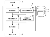
- FIG. 1 is a block diagram showing a schematic configuration of a medical image diagnosis support system using an embodiment of a medical image display control apparatus and method and a program according to the present invention.
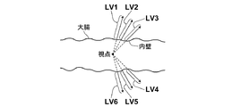
- the figure which shows typically an example of the light vector extended from each pixel of a virtual endoscopic image The flowchart for demonstrating the effect
- the figure which shows an example of a virtual endoscopic image The figure which shows an example of the superimposition image which superimposed the specific area projection image on the virtual endoscopic image
- FIG. 1 is a block diagram showing a schematic configuration of the medical image diagnosis support system of the present embodiment.
- the medical image diagnosis support system of the present embodiment includes a medical image display control device 1, a three-dimensional image storage server 2, a display 3, and an input device 4, as shown in FIG.
- the medical image display control apparatus 1 is a computer in which the medical image display control program of this embodiment is installed in a computer.
- the medical image display control apparatus 1 includes a central processing unit (CPU) and a semiconductor memory, and storage devices such as a hard disk and an SSD (Solid State Drive).
- the storage device is installed with the medical image display control program of the present embodiment, and the medical image display control program is executed by the central processing unit, whereby a three-dimensional image acquisition unit 10 as shown in FIG.
- the organ extraction unit 11, the inner wall image generation unit 12, the specific area projection image generation unit 13, and the display control unit 14 operate.
- the three-dimensional image acquisition unit 10 acquires a three-dimensional image 5 of a subject imaged in advance before surgery or before examination.
- the three-dimensional image 5 for example, volume data reconstructed from slice data output from a CT apparatus or an MRI (Magnetic Resonance Imaging) apparatus, an MS (Multi Slice) CT apparatus, or a cone beam CT apparatus is output. There is volume data.
- the three-dimensional image 5 is stored in advance in the three-dimensional image storage server 2 together with the identification information of the subject, and the three-dimensional image acquisition unit 10 corresponds to the identification information of the subject input in the input device 4.
- the image 5 is read from the three-dimensional image storage server 2.
- the three-dimensional image acquisition unit 10 may acquire a large number of slice data and generate volume data.
- the three-dimensional image acquisition unit 10 acquires a three-dimensional image including the large intestine. In addition, you may make it acquire not only large intestine but the three-dimensional image containing other luminal organs, such as a bronchi and a stomach.
- the organ extraction unit 11 receives the 3D image 5 acquired by the 3D image acquisition unit 10 and extracts voxel data of an organ or bone in the subject from the input 3D image 5.
- the organ include a large intestine, a small intestine, a kidney, a bronchus, and a blood vessel.
- the present invention is not limited to this, and other organs may be used.
- Which organ is extracted is set by the user using the input device 4.
- voxel data of the large intestine and bone are extracted and acquired.
- a method for extracting the large intestine region first, based on the three-dimensional image 5, a plurality of axially disconnected images having a section perpendicular to the body axis (axial) are generated.
- a processing for separating the external region and the internal region is performed on the cut image by a known method based on the body surface. For example, a binarization process is performed on the input axial position discontinuity image, a contour is extracted by a contour extraction process, and the inside of the extracted contour is extracted as a body (human body) region.
- binarization processing is performed on the axial discontinuity image of the in-vivo region with a threshold value, and a colon region candidate in each axial discontinuity image is extracted. Specifically, since air is contained in the large intestine tube, a threshold value (for example, ⁇ 600 or less) corresponding to the CT value of the air is set, and binarization processing is performed. Are extracted as colon region candidates.
- a threshold value for example, ⁇ 600 or less
- the large intestine region is acquired by extracting only the portion where the extracted large intestine region candidates in the body are connected between the respective axial dislocation image data.
- the method for acquiring the large intestine region is not limited to the above method, and other known methods such as RegionRegGrowing method and Level Set method may be used.
- the organ extraction unit 11 outputs the extracted large intestine voxel data to the inner wall image generation unit 12 and outputs the bone voxel data to the specific area projection image generation unit 13.
- the inner wall image generation unit 12 generates an inner wall image representing the inner wall of the large intestine based on the input large intestine voxel data.
- the inner wall image generation unit 12 of the present embodiment generates a virtual endoscopic image that is an image obtained by virtually imaging the lumen of the large intestine with an endoscope as the inner wall image.
- the inner wall image generation unit 12 projects voxel data in a plurality of ray directions radially extending around a line-of-sight vector based on a preset viewpoint and line-of-sight direction onto a predetermined projection plane.
- An image by central projection is generated as a virtual endoscopic image.
- a specific method of central projection for example, a known volume rendering method or the like can be used.
- the viewpoint of the virtual endoscopic image may be set by the user specifying an arbitrary point using the input device 4 on the three-dimensional image of the large intestine displayed on the display, for example.
- a predetermined point on the center line of the large intestine extracted based on the voxel data of the large intestine may be set automatically or manually.
- the user may manually set an arbitrary direction for the line-of-sight direction, or the traveling direction of the central line of the large intestine may be set as the line-of-sight direction.
- the inner wall image generation unit 12 outputs the virtual endoscopic image generated as described above to the display control unit 14.
- the specific area projection image generation unit 13 acquires a representative value of voxel data on a light vector that extends a predetermined distance from each pixel of the virtual endoscopic image toward the outside of the large intestine, and uses the representative value as a virtual endoscope. A specific area projection image projected on the mirror image is generated.
- FIG. 2 schematically shows an example of the light vectors LV1 to LV6 extending from each pixel of the virtual endoscopic image.
- the light vector LV1 to LV6 in the present embodiment is a vector starting from each pixel of the virtual endoscopic image and extending in the same direction as the light ray direction of the virtual endoscopic image, and a predetermined distance. (Length).
- the distance between the light vectors LV1 to LV6 is set in advance depending on the depth to be observed.
- the distances of the light vectors LV1 to LV6 may be the same or different.
- the distance between the light vectors LV1 to LV6 may be changed by the user while observing the display of the specific area projection image described later. The distance may be changed using the input device 4.
- the specific area projection image generation unit 13 acquires a representative value of voxel data on each of the light vector LV1 to LV6 shown in FIG.
- a representative value a maximum value, a minimum value, an average value, a total value, or the like can be used, but any other value may be used as long as it is a value representative of voxel data on a vector.
- each representative value of the voxel data on each of the light vectors LV1 to LV6 is projected onto the virtual endoscopic image to generate a specific area projection image.
- the specific region projection image generated as described above can include a contrasted blood vessel, fat, or mass inside the large intestine wall, but there are bones around the large intestine as described above.
- the image of the bone is included in the specific area projection image, and the blood vessel image or the like is very difficult to see.
- the specific area projection image is generated by setting the voxels to be visualized so that the image of the bone or organ that is not the visible object is not included in the specific area projection image.
- the specific area projection image generation unit 13 in the present embodiment acquires the bone voxel data output from the organ extraction unit 11, excludes the bone voxel data from the voxel data of the three-dimensional image 5, The voxel data of the three-dimensional image 5 after the exclusion is set as a voxel to be visualized. Then, the representative value of the voxel data to be visualized among the voxel data on each of the light vectors LV1 to LV6 is acquired. Thereby, a bone image that is not a visualization target can be excluded from the specific region projection image, and a specific region projection image that allows easy observation of a blood vessel image or the like inside the large intestine wall can be generated.
- the voxel data of the bone is not targeted for visualization.
- the present invention is not limited to the bone, and voxel data of an organ such as a kidney around the large intestine may be excluded.
- the organs to be excluded are set in advance by the user using the input device 4.
- the voxel data such as bones and kidneys may be set to zero, or masked when obtaining a representative value.
- the display control unit 14 receives the virtual endoscopic image generated by the inner wall image generation unit 12 and the specific region projection image generated by the specific region projection image generation unit 13 and inputs the specific region to the virtual endoscope image.
- a superimposed image is generated by superimposing the projected images, and this superimposed image is displayed on the display 3.
- the input device 4 is provided with a mouse, a keyboard, etc., and receives an operation input by the user.
- the input device 4 of the present embodiment includes the viewpoint and line-of-sight direction used when generating the virtual endoscopic image, the length of the optical vector used when generating the specific area projection image, and the specific area projection. It accepts setting inputs for bones or organs that are not subject to image visualization.
- the identification information of the subject is input by the user using the input device 4, and the three-dimensional image acquisition unit 10 of the medical image display control device 1 performs the three-dimensional image 5 corresponding to the input identification information of the subject. Is read from the three-dimensional image storage server 2 and acquired (S10).
- the three-dimensional image 5 acquired by the three-dimensional image acquisition unit 10 is input to the organ extraction unit 11, and the organ extraction unit 11 extracts voxel data of the large intestine and bone based on the input three-dimensional image 5.
- the large intestine voxel data acquired by the organ extraction unit 11 is input to the inner wall image generation unit 12, and the inner wall image generation unit 12 generates a virtual endoscopic image based on the input large intestine voxel data,
- the generated virtual endoscopic image is output to the display control unit 14 (S14).
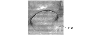
- FIG. 4 shows an example of a virtual endoscopic image.
- the three-dimensional image 5 acquired by the three-dimensional image acquisition unit 10 and the bone voxel data extracted by the organ extraction unit 11 are input to the specific region projection image generation unit 13.
- the specific area projection image generation unit 13 sets the voxel data to be visualized by excluding the bone voxel data from the voxel data of the input three-dimensional image 5, and sets the voxel data to be visualized and the above-described light rays.
- representative values are acquired to generate a specific area projection image, and the generated specific area projection image is output to the display control unit 14 (S18).
- the display control unit 14 superimposes the specific area projection image on the input virtual endoscopic image to generate a superimposed image, and displays the generated superimposed image on the display 3 (S20).
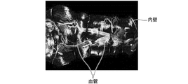
- FIG. 5 shows an example of a superimposed image generated by superimposing a specific area projection image including a blood vessel image on a virtual endoscopic image.
- FIG. 6 is an example of a superimposed image when a specific region projection image is generated without excluding bone voxel data as in the present embodiment. As shown in FIG. 6, a bone image appears. Therefore, it can be seen that the blood vessel image is very difficult to see.
- the virtual endoscopic image is generated by the inner wall image generation unit 12.
- the inner wall image representing the inner wall of the luminal organ is not limited to this and is expanded.
- An image may be generated.
- the developed image is an image obtained by extending the luminal organ in a straight line, further opening the tube, and developing the inner wall side.
- the developed image is a projection of the voxel data of the inner wall on each ray extended in all radial directions (360 °) from the center line on each cross section orthogonal to the length direction of the luminal organ. It is.
- a method for generating a developed image is known in, for example, Japanese Patent Application Laid-Open No. 2008-259713, and detailed description thereof is omitted.
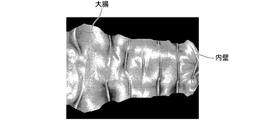
- FIG. 7 shows an example of a developed image of the large intestine.
- the developed image shown in FIG. 7 is obtained by changing the number of light beams in each cross section in accordance with the thickness of each cross section of the large intestine. Specifically, the number of light beams is reduced as the cross section is thinner. The thicker the cross section, the greater the number of rays. In this way, by changing the number of light rays in each cross section, an image close to the state in which the large intestine is actually developed can be generated like the developed image shown in FIG. In addition, when the number of light beams in each cross section is not changed, the developed image has a simple rectangular shape, but the observation range becomes narrower than this case, so that the labor for observation can be reduced. it can.
- the specific area projection image generation unit 13 extends a light beam extending from each pixel of the developed image by a preset distance toward the outside of the luminal organ. A representative value of the voxel on the vector is acquired, and a specific area projection image in which the representative value is projected on the developed image is generated.
- FIG. 8 schematically shows an example of the light vectors LV1 to LV5 extending from each pixel representing the inner wall in the developed image.
- ray vectors LV1 to LV5 are vectors starting from each pixel representing the inner wall in the developed image and extending in the radial direction from the center line of the large intestine, and the distance (length) is desired to be observed. It shall be preset according to the depth.
- the light vectors LV1 to LV5 may have the same distance or different distances.
- the number of the light vectors may be changed according to the thickness of each cross section as in the case of generating the developed image. Specifically, the number of the light vectors may be decreased as the cross section is thinner, and the number of the light vectors may be increased as the cross section is thicker.
- each of the light vectors V1 to LV5 As a representative value of each of the light vectors V1 to LV5, a maximum value, an average value, a total value, a minimum value, or the like can be used as in the above embodiment, but other values representative of the voxel data on the vector are used. Any value is acceptable.
- each representative value of the voxel data on each of the light vectors LV1 to LV5 is projected onto the developed image to generate a specific area projection image.
- the bone that is not a visible object is used.
- the specific region projection image is generated by setting the voxels to be visualized so that the image of the organ or the organ is not included in the specific region projection image.
- the voxel data of the bone and the voxel data of the kidney are excluded from the voxel data of the three-dimensional image 5, and the voxel data of the three-dimensional image 5 after the exclusion is used as the voxel to be visualized.
- the inner wall image generation unit 12 may generate an expanded cross-sectional image as the inner wall image.
- An expanded cross-sectional image is an image obtained by extending a luminal organ in a straight line and cutting a tube vertically.
- FIG. 11 shows an example of an enlarged cross-sectional image of the large intestine.
- a method for generating an expanded cross-sectional image is known in, for example, Japanese Patent Application Laid-Open No. 2008-259713, Japanese Patent Application Laid-Open No. 2008-259712, Japanese Patent Application Laid-Open No. 2012-24517, and the like, and thus detailed description thereof is omitted.
- the direction (angle) for setting the light vector is a expanded image except that the expanded expanded image is smaller. It is the same.
- the voxel data to be visualized is set by excluding the voxel data of bones and kidneys from the voxel data of the three-dimensional image 5, but in this way voxel data that is not the visualization target is set.
- the voxel data to be visualized may be extracted from the voxel data of the three-dimensional image 5, and the specific region projection image may be generated using the extracted voxel data.
- the organ extraction unit 11 extracts the blood vessel voxel data from the three-dimensional image 5 and acquires and specifies the representative value of the blood vessel voxel data on the light vector.
- An area projection image may be generated.
- organs to be visualized are not limited to blood vessels, but may include other specific organs.
- the organ to be visualized is preset by the user using the input device 4.
- the luminal organ to be observed is not limited to the large intestine as described above, and may be other luminal organs, for example,
- a specific area projection image including lymph in the bronchus can be generated and displayed.
- a specific area projection image including blood vessels and tumors in the stomach wall can be generated and displayed.
- the maximum value, minimum value, average value, or total value of the voxels to be visualized is acquired as a representative value. Any one of them may be selected by the user using the input device 4. That is, selection of one of at least two of the maximum value, the minimum value, the average value, and the total value may be accepted, and the accepted value may be used as the representative value.
- the display control unit 14 assigns different colors according to the size of the representative value of each pixel and displays the specific area projection image
- the specific area projection image having a hue according to the user's preference is displayed.
- a superimposed image superimposed on the inner wall image can be displayed.
- one voxel having the same value as the representative value or the closest value among the voxels to be visualized on the light vector is specified, and the voxel and the inner wall of the luminal organ (light ray)
- the distance to the start point of the vector may be calculated, and the brightness and saturation of the pixels in the specific area projection image may be changed according to the distance. For example, if the brightness and saturation are lowered as the distance increases, the perspective of the specific area projection image can be given.
- Digital cleansing processing may be performed to remove the residual image.
- the digital cleansing process is a process of removing an image of a residue portion that has been tagged (labeled) with a contrast agent in advance from a three-dimensional image.
Landscapes
- Health & Medical Sciences (AREA)
- Life Sciences & Earth Sciences (AREA)
- Surgery (AREA)
- Engineering & Computer Science (AREA)
- Medical Informatics (AREA)
- Biophysics (AREA)
- Molecular Biology (AREA)
- Physics & Mathematics (AREA)
- Nuclear Medicine, Radiotherapy & Molecular Imaging (AREA)
- Optics & Photonics (AREA)
- Pathology (AREA)
- Radiology & Medical Imaging (AREA)
- Biomedical Technology (AREA)
- Heart & Thoracic Surgery (AREA)
- Veterinary Medicine (AREA)
- Public Health (AREA)
- Animal Behavior & Ethology (AREA)
- General Health & Medical Sciences (AREA)
- Signal Processing (AREA)
- Computer Vision & Pattern Recognition (AREA)
- High Energy & Nuclear Physics (AREA)
- Apparatus For Radiation Diagnosis (AREA)
- Magnetic Resonance Imaging Apparatus (AREA)
Abstract
【課題】管腔臓器の内壁を表す仮想内視鏡画像を表示させるとともに、管腔臓器の内部に存在する血管などを観察しやすい画像を表示させる。 【解決手段】被検体の3次元画像に基づいて、被検体の管腔臓器の内壁を表す内壁画像を生成する内壁画像生成部(12)と、内壁画像の各画素から管腔臓器の外側に向かって予め設定された距離だけ延びた光線ベクトル上の複数のボクセルに基づいて代表値を取得し、その代表値を内壁画像上に投影した特定領域投影画像を生成する特定領域投影画像生成部(13)と、内壁画像に特定領域投影画像を重ねて表示させる表示制御部(14)とを備え、特定領域投影画像生成部(13)が、3次元画像のボクセルのうち、可視化対象の一部のボクセルを設定し、光線ベクトル上の複数のボクセルのうち、可視化対象のボクセルの代表値を取得する。
Description
本発明は、被検体の管状臓器の内壁を表す内壁画像を生成して表示させる医用画像表示制御装置および方法並びにプログラムに関するものである。
近年、CT(Computed Tomography)装置などのモダリティによって撮影された3次元画像から患者の大腸、小腸、気管支および血管などの管腔臓器を抽出し、その抽出した管腔臓器の3次元画像を画像診断に用いることが行われている。
たとえば、大腸コロノグラフィーにおいては、大腸領域の3次元画像に基づいて、その大腸領域の内部を通過する内視鏡の経路を決定し、その決定した経路に沿って視点を動かしながら実際にその視点から内視鏡によって撮影された画像と類似した仮想内視鏡画像を生成し、この仮想内視鏡画像を表示することによって目標とする地点までの経路をナビゲーションする技術が提案されている。
ここで、上述したような仮想内視鏡画像は、大腸のような管腔臓器の内壁を表す画像であるため、大腸の内腔の様子を観察するには適しているが、たとえば大腸壁内部の血管や脂肪や腫瘤などを観察するのには適していない。また、仮想内視鏡画像は、管腔臓器の内壁の表面の状態を表したものであるため、たとえば周囲組織と比べて隆起の程度が小さいポリープなどの発見にはあまり適しておらず、病変部を見逃すおそれがある。
そこで、特許文献1から特許文献3においては、仮想内視鏡表示において、仮想内視鏡画像の光線方向に存在する最大値や加算値を仮想内視鏡画像上に投影して表示することによって、管腔臓器の外側に存在する臓器などを表示することが提案されている。
しかしながら、特許文献1から特許文献3に記載の方法では、たとえば大腸周辺に骨が存在する場合、仮想内視鏡画像上に骨まで投影されてしまうので、本来観察したい大腸壁内部の血管や脂肪や腫瘍などの画像と骨の画像との区別が容易でなく、血管などを観察しづらい画像となってしまう。
本発明は、上記事情に鑑み、管腔臓器の内壁を表す仮想内視鏡画像などを表示させるとともに、管腔臓器の内部に存在する血管などを観察しやすい画像を表示させることができる医用画像表示制御装置および方法並びにプログラムを提供することを目的とするものである。
本発明の医用画像表示制御装置は、被検体の3次元画像に基づいて、被検体の管腔臓器の内壁を表す内壁画像を生成する内壁画像生成部と、内壁画像の各画素から管腔臓器の外側に向かって予め設定された距離だけ延びた光線ベクトル上の複数のボクセルに基づいて代表値を取得し、その代表値を内壁画像上に投影した特定領域投影画像を生成する特定領域投影画像生成部と、内壁画像に特定領域投影画像を重ねて表示させる表示制御部とを備え、特定領域投影画像生成部が、3次元画像のボクセルのうち、可視化対象の一部のボクセルを設定し、光線ベクトル上の複数のボクセルのうち、可視化対象のボクセルの代表値を取得するものであることを特徴とする。
また、上記本発明の医用画像表示制御装置は、可視化対象としない予め設定された骨または臓器を表すボクセルを3次元画像のボクセルから抽出する臓器抽出部を備えたものとし、特定領域投影画像生成部を、3次元画像のボクセルから予め設定された骨または臓器のボクセルを除去し、その除去後の3次元画像のボクセルを可視化対象のボクセルとして代表値を取得するものとできる。
また、可視化対象とする予め設定された臓器を表すボクセルを3次元画像のボクセルから抽出する臓器抽出部を備えたものとし、特定領域投影画像生成部を、予め設定された臓器を表すボクセルを可視化対象のボクセルとして代表値を取得するものとできる。
また、内壁画像生成部を、管腔臓器の内壁を内視鏡によって仮想的に撮影した画像である仮想内視鏡画像を内壁画像として生成するものとできる。
また、内壁画像生成部を、管腔臓器を切り開いて内壁側を展開した展開画像を内壁画像として生成するものとできる。
また、内壁画像生成部を、管腔臓器を縦切りにした伸長断面画像を内壁画像として生成するものとできる。
また、特定領域投影画像生成部を、代表値として最大値、最小値、平均値または合計値を取得するものとできる。
また、特定領域投影画像生成部を、可視化対象のボクセルの最大値、最小値、平均値および合計値のうちの少なくとも2つの中の1つの値の選択を受け付け、その受け付けた値を代表値とし、表示制御部を、代表値の大きさに応じて異なる色を割り当てて特定領域投影画像を表示させるものとできる。
また、可視化対象とする臓器を血管とすることができる。
また、管腔組織を大腸とすることができる。
また、3次元画像を、デジタルクレンジング処理が施されたものとできる。
本発明の医用画像表示制御方法は、被検体の3次元画像に基づいて、被検体の管腔臓器の内壁を表す内壁画像を生成し、内壁画像の各画素から管腔臓器の外側に向かって予め設定された距離だけ延びた光線ベクトル上の複数のボクセルに基づいて代表値を取得し、その代表値を内壁画像上に投影した特定領域投影画像を生成し、内壁画像に特定領域投影画像を重ねて表示させる医用画像表示方法であって、特定領域投影画像を生成する際、3次元画像のボクセルのうち、可視化対象の一部のボクセルを設定し、光線ベクトル上の複数のボクセルのうち、可視化対象のボクセルの代表値を取得することを特徴とする。
本発明の医用画像表示制御プログラムは、コンピュータを、被検体の3次元画像に基づいて、被検体の管腔臓器の内壁を表す内壁画像を生成する内壁画像生成部と、内壁画像の各画素から管腔臓器の外側に向かって予め設定された距離だけ延びた光線ベクトル上の複数のボクセルに基づいて代表値を取得し、その代表値を内壁画像上に投影した特定領域投影画像を生成する特定領域投影画像生成部と、内壁画像に特定領域投影画像を重ねて表示させる表示制御部として機能させる医用画像表示制御プログラムであって、特定領域投影画像生成部が、3次元画像のボクセルのうち、可視化対象の一部のボクセルを設定し、光線ベクトル上の複数のボクセルのうち、可視化対象のボクセルの代表値を取得するものであることを特徴とする。
本発明の医用画像表示制御装置および方法並びにプログラムによれば、被検体の3次元画像に基づいて、被検体の管腔臓器の内壁を表す内壁画像を生成し、内壁画像の各画素から管腔臓器の外側に向かって予め設定された距離だけ延びた光線ベクトル上の複数のボクセルに基づいて代表値を取得し、その代表値を内壁画像上に投影した特定領域投影画像を生成し、内壁画像に特定領域投影画像を重ねて表示させる際、3次元画像のボクセルのうち、可視化対象の一部のボクセルを設定し、光線ベクトル上の複数のボクセルのうち、可視化対象のボクセルの代表値を取得するようにしたので、たとえば骨などのボクセルを上述した可視化対象のボクセルに含めないことによって、特定領域投影画像に骨などの画像を含めないようにすることができ、管腔臓器の内部に存在する可視化対象の血管などを観察しやすい特定領域投影画像を仮想内視鏡画像上に投影して表示させることができる。これにより観察者の労力の低減を図ることができる。
以下、本発明の医用画像表示制御装置および方法並びにプログラムの一実施形態を用いた医用画像診断支援システムについて、図面を参照しながら詳細に説明する。図1は、本実施形態の医用画像診断支援システムの概略構成を示すブロック図である。
本実施形態の医用画像診断支援システムは、図1に示すように、医用画像表示制御装置1と、3次元画像保管サーバ2と、ディスプレイ3と、入力装置4とを備えている。
医用画像表示制御装置1は、コンピュータに本実施形態の医用画像表示制御プログラムがインストールされたものである。
医用画像表示制御装置1は、中央処理装置(CPU)および半導体メモリや、ハードディスクやSSD(Solid State Drive)等のストレージデバイスを備えている。ストレージデバイスには、本実施形態の医用画像表示制御プログラムがインストールされており、この医用画像表示制御プログラムが中央処理装置によって実行されることによって、図1に示すような3次元画像取得部10、臓器抽出部11、内壁画像生成部12、特定領域投影画像生成部13および表示制御部14が動作する。
医用画像表示制御装置1は、中央処理装置(CPU)および半導体メモリや、ハードディスクやSSD(Solid State Drive)等のストレージデバイスを備えている。ストレージデバイスには、本実施形態の医用画像表示制御プログラムがインストールされており、この医用画像表示制御プログラムが中央処理装置によって実行されることによって、図1に示すような3次元画像取得部10、臓器抽出部11、内壁画像生成部12、特定領域投影画像生成部13および表示制御部14が動作する。
3次元画像取得部10は、手術前または検査前などに予め撮影された被検体の3次元画像5を取得するものである。3次元画像5としては、たとえばCT装置やMRI(Magnetic Resonance Imaging)装置などから出力されたスライスデータから再構成されたボリュームデータや、MS(Multi Slice)CT装置やコーンビームCT装置から出力されたボリュームデータなどがある。3次元画像5は、3次元画像保管サーバ2に被検体の識別情報とともに予め保管されており、3次元画像取得部10は、入力装置4において入力された被検体の識別情報に対応する3次元画像5を3次元画像保管サーバ2から読み出すものである。なお、3次元画像取得部10において多数のスライスデータを取得してボリュームデータを生成するようにしてもよい。
本実施形態においては、3次元画像取得部10は、大腸を含む3次元画像を取得するものとする。なお、大腸に限らず、気管支や胃などのその他の管腔臓器を含む3次元画像を取得するようにしてもよい。
臓器抽出部11は、3次元画像取得部10によって取得された3次元画像5が入力され、その入力された3次元画像5から被検体内の臓器または骨のボクセルデータを抽出するものである。臓器としては、たとえば大腸、小腸、腎臓、気管支または血管などがあるが、これに限らずその他の臓器でもよく、どの臓器を抽出するかはユーザによって入力装置4を用いて設定される。なお、本実施形態においては大腸と骨のボクセルデータを抽出して取得するものとする。
大腸領域を抽出する方法としては、具体的には、まず、3次元画像5に基づいて体軸に垂直な断面(軸位断;axial)の軸位断画像を複数生成し、その各軸位断画像に対して、公知の手法により、体表を基準に体外と体内領域を分離する処理を行う。たとえば、入力された軸位断画像に対して二値化処理を施し、輪郭抽出処理により輪郭を抽出し、その抽出した輪郭内部を体内(人体)領域として抽出する。
次に、体内領域の軸位断画像に対して閾値による二値化処理を行い、各軸位断画像における大腸の領域の候補を抽出する。具体的には、大腸の管内には空気が入っているため、空気のCT値に対応する閾値(たとえば、-600以下)を設定して二値化処理を行い、各軸位断画像の体内の空気領域を大腸領域候補として抽出する。
最後に、各軸位断画像データ間で、抽出された体内の大腸領域候補がつながる部分のみを抽出することによって大腸領域を取得する。なお、大腸領域を取得する方法としては、上記の方法に限らず、その他にもRegion Growing法やLevel Set法など公知な方法を用いるようにしてもよい。
また、骨を抽出する方法としては、たとえば「“CT画像からの骨盤と大腿骨のセグメンテーション”,電子情報通信学会技術研究報告,MI,医用画像,100(596),99-104,2001」に記載のような公知な手法を用いることができる。
臓器抽出部11は、抽出した大腸のボクセルデータを内壁画像生成部12に出力するとともに、骨のボクセルデータを特定領域投影画像生成部13に出力するものである。
内壁画像生成部12は、入力された大腸のボクセルデータに基づいて、大腸の内壁を表す内壁画像を生成するものである。本実施形態の内壁画像生成部12は、内壁画像として、内視鏡によって仮想的に大腸の内腔を撮影した画像である仮想内視鏡画像を生成するものである。
具体的には、内壁画像生成部12は、予め設定された視点と視線方向とに基づく視線ベクトルを中心として放射線状に伸ばした複数の光線方向上のボクセルデータを、所定の投影面に投影した中心投影による画像を仮想内視鏡画像として生成するものである。なお、中心投影の具体的な方法としては、たとえば公知のボリュームレンダリング手法等を用いることができる。
また、仮想内視鏡画像の視点については、たとえばディスプレイ上に表示された大腸の3次元画像上において、ユーザが入力装置4を用いて任意の点を指定することによって設定するようにしてもよいし、大腸のボクセルデータに基づいて抽出された大腸の中心線上の所定の点を自動または手動で指定することによって設定するようにしてもよい。また、視線方向についてもユーザが任意の方向を手動で設定するようにしてもよいし、大腸の中心線の進行方向を視線方向としてもよい。
内壁画像生成部12は、上述したようにして生成した仮想内視鏡画像を表示制御部14に出力するものである。
特定領域投影画像生成部13は、仮想内視鏡画像の各画素から大腸の外側に向かって所定の距離だけ延びた光線ベクトル上のボクセルデータの代表値を取得し、その代表値を仮想内視鏡画像上に投影した特定領域投影画像を生成するものである。
図2は、仮想内視鏡画像の各画素から延びた光線ベクトルLV1~LV6の一例を模式的に示したものである。本実施形態における光線ベクトルLV1~LV6は、図2に示すように、仮想内視鏡画像の各画素を始点とし、仮想内視鏡画像の光線方向と同じ方向に延びるベクトルであり、所定の距離(長さ)を有するものである。光線ベクトルLV1~LV6の距離については観察したい深さによって予め設定されるものとする。各光線ベクトルLV1~LV6の距離は同じでも良いし、異なる距離としてもよい。
また、光線ベクトルLV1~LV6の距離については、ユーザが、後述する特定領域投影画像の表示を観察しながら変更できるようにしてもよい。距離の変更は、入力装置4を用いて行うようにすればよい。
特定領域投影画像生成部13は、図2に示す各光線ベクトルLV1~LV6のそれぞれについて、そのベクトル上のボクセルデータの代表値を取得するものである。代表値としては、最大値、最小値、平均値または合計値などを用いることができるが、その他にもベクトル上のボクセルデータを代表する値であれば如何なる値でもよい。
そして、各光線ベクトルLV1~LV6上のボクセルデータの各代表値が、仮想内視鏡画像上に投影されて特定領域投影画像が生成される。
ここで、上述したようにして生成された特定領域投影画像には、大腸壁内部の造影された血管や脂肪や腫瘤などを含めることができるが、上述したように大腸周辺に骨などがある場合には、この骨の画像まで特定領域投影画像に含まれることになり、血管画像などを非常に見づらい画像となってしまう。
そこで、本実施形態においては、可視対象ではない骨や臓器の画像が特定領域投影画像に含まれないように可視化対象のボクセルを設定して特定領域投影画像を生成する。具体的には、本実施形態における特定領域投影画像生成部13は、臓器抽出部11から出力された骨のボクセルデータを取得し、3次元画像5のボクセルデータから骨のボクセルデータを除外し、その除外後の3次元画像5のボクセルデータを可視化対象のボクセルとして設定する。そして、各光線ベクトルLV1~LV6上のボクセルデータのうち、可視化対象のボクセルデータの代表値を取得する。これにより特定領域投影画像から可視化対象ではない骨の画像を除外することができ、大腸壁内部の血管画像などを観察し易い特定領域投影画像を生成することができる。
なお、本実施形態においては、骨のボクセルデータを可視化対象としないようにしたが、骨に限らず、たとえば大腸の周辺にある腎臓などの臓器のボクセルデータを除外するようにしてもよい。除外対象の臓器については、ユーザによって入力装置4を用いて予め設定される。
また、骨や腎臓などのボクセルデータを除外する方法としては、骨や腎臓などのボクセルデータをゼロに設定するようにしてもよいし、代表値を取得する際にマスクするようにしてもよい。
表示制御部14は、内壁画像生成部12において生成された仮想内視鏡画像と、特定領域投影画像生成部13において生成された特定領域投影画像とが入力され、仮想内視鏡画像に特定領域投影画像を重ね合せた重畳画像を生成し、この重像画像をディスプレイ3に表示させるものである。
入力装置4は、マウスやキーボードなどを備えたものであり、ユーザによる操作入力を受け付けるものである。本実施形態の入力装置4は、上述したように仮想内視鏡画像を生成する際に用いられる視点や視線方向、特定領域投影画像を生成する際に用いられる光学ベクトルの長さ、特定領域投影画像の可視化対象としない骨または臓器などの設定入力を受け付けるものである。
次に、本実施形態の医用画像診断支援システムの作用について、図3に示すフローチャートを参照しながら説明する。
まず、入力装置4を用いてユーザによって被検体の識別情報が入力され、医用画像表示制御装置1の3次元画像取得部10は、その入力された被検体の識別情報に対応する3次元画像5を3次元画像保管サーバ2から読み出して取得する(S10)。
3次元画像取得部10によって取得された3次元画像5は、臓器抽出部11に入力され、臓器抽出部11は、入力された3次元画像5に基づいて大腸と骨のボクセルデータを抽出して取得する(S12)。
臓器抽出部11によって取得された大腸のボクセルデータは、内壁画像生成部12に入力され、内壁画像生成部12は、入力された大腸のボクセルデータに基づいて仮想内視鏡画像を生成し、その生成した仮想内視鏡画像を表示制御部14に出力する(S14)。図4は、仮想内視鏡画像の一例を示すものである。
一方、3次元画像取得部10によって取得された3次元画像5と臓器抽出部11において抽出された骨のボクセルデータとが、特定領域投影画像生成部13に入力される。そして、特定領域投影画像生成部13は、入力された3次元画像5のボクセルデータから骨のボクセルデータを除外することによって可視化対象のボクセルデータを設定し、その可視化対象のボクセルデータと上述した光線ベクトルLV1~LV6とに基づいて代表値を取得して特定領域投影画像を生成し、その生成した特定領域投影画像を表示制御部14に出力する(S18)。
表示制御部14は、入力された仮想内視鏡画像に対して特定領域投影画像を重ね合せて重畳画像を生成し、その生成した重畳画像をディスプレイ3に表示させる(S20)。図5は、仮想内視鏡画像に対して血管画像を含む特定領域投影画像を重ね合せて生成された重畳画像の一例を示すものである。なお、図6は、本実施形態のように骨のボクセルデータを除外することなく特定領域投影画像を生成した場合における重畳画像の一例であり、図6に示すように、骨の画像が現れているために血管画像が非常に見づらくなっているのがわかる。
また、上記実施形態の医用画像診断支援システムにおいては、内壁画像生成部12において仮想内視鏡画像を生成するようにしたが、管腔臓器の内壁を表す内壁画像としてはこれに限らず、展開画像を生成するようにしてもよい。展開画像は、管腔臓器を直線状に伸長させ、さらに管を切り開いて内壁側を展開した画像である。展開画像は、管腔臓器の長さ方向に直交する各断面上において、中心線から全ての半径方向(360°)に伸ばした各光線上の内壁のボクセルデータを2次元画像上に投影したものである。なお、展開画像の生成方法については、たとえば特開2008-259713号公報などで公知であるので詳細な説明は省略する。
図7は、大腸の展開画像の一例を示すものである。図7に示す展開画像は、大腸の各断面における太さに応じて、各断面における光線の本数を変化させたものであり、具体的には、太さが細い断面ほど光線の本数を少なくし、太さが太い断面ほど光線の本数を多くしている。このように各断面における光線の本数を変化させることによって、図7に示す展開画像のように実際に大腸を展開した状態に近い画像を生成することができる。また、各断面における光線の本数を変化させなかった場合には、展開画像は単純な長方形の形状となるが、この場合と比較すると観察範囲が狭くなるので、観察する際の労力を減らすことができる。
そして、内壁画像生成部12において展開画像を生成する場合には、特定領域投影画像生成部13は、その展開画像の各画素から管腔臓器の外側に向かって予め設定された距離だけ延びた光線ベクトル上のボクセルの代表値を取得し、その代表値を展開画像上に投影した特定領域投影画像を生成する。
図8は、展開画像における内壁を表す各画素から延びた光線ベクトルLV1~LV5の一例を模式的に示したものである。光線ベクトルLV1~LV5は、図8に示すように、展開画像における内壁を表す各画素を始点とし、大腸の中心線から全ての半径方向に延びるベクトルであり、その距離(長さ)は観察したい深さによって予め設定されるものとする。各光線ベクトルLV1~LV5の距離は同じにしてもよいし、異なる距離としてもよい。
なお、光線ベクトルも大腸の各断面について設定されるものであるが、展開画像を生成する場合と同様に、各断面の太さに応じて、光線ベクトルの本数を変化させるようにしてもよい。具体的には、太さが細い断面ほど光線ベクトルの本数を少なくし、太さが太い断面ほど光線ベクトルの本数を多くするようにしてもよい。
各光線ベクトルV1~LV5の代表値としては、上記実施形態と同様に、最大値、平均値、合計値または最小値などを用いることができるが、その他にもベクトル上のボクセルデータを代表する値であれば如何なる値でもよい。
そして、各光線ベクトルLV1~LV5上のボクセルデータの各代表値が、展開画像上に投影されて特定領域投影画像が生成されるが、この場合も上記実施形態と同様に、可視対象ではない骨や臓器の画像が特定領域投影画像に含まれないように可視化対象のボクセルを設定して特定領域投影画像を生成する。具体的には、上記実施形態と同様に、3次元画像5のボクセルデータから骨のボクセルデータや腎臓のボクセルデータを除外し、その除外後の3次元画像5のボクセルデータを可視化対象のボクセルとして設定する。
また、上述した展開画像の他に、内壁画像生成部12において、内壁画像として伸長断面画像を生成するようにしてもよい。伸長断面画像とは、管腔臓器を直線状に伸長させ、管を縦切りにしたような画像である。図11は、大腸の伸長断面画像の一例を示すものである。なお、伸長断面画像の生成方法については、たとえば特開2008-259713号公報や特開2008-259712号公報や特開2012-24517号公報などで公知であるので詳細な説明は省略する。
内壁画像生成部12において伸長展開画像を生成する場合における特定領域投影画像の生成方法については、光線ベクトルを設定する方向(角度)が、伸長展開画像の方が少なくなること以外は展開画像の場合と同様である。
また、上記実施形態においては、3次元画像5のボクセルデータから骨や腎臓のボクセルデータを除外することによって可視化対象のボクセルデータを設定するようにしたが、このように可視化対象ではないボクセルデータを特定するのではなく、3次元画像5のボクセルデータから可視化対象とするボクセルデータを抽出し、その抽出したボクセルデータを用いて特定領域投影画像を生成するようにしてもよい。具体的には、たとえば血管を可視化対象とする場合には、臓器抽出部11において3次元画像5から血管のボクセルデータを抽出し、光線ベクトル上の血管のボクセルデータの代表値を取得して特定領域投影画像を生成するようにしてもよい。
また、可視化対象の臓器は血管に限らず、その他の特定の臓器も含めるようにしてもよい。可視化対象の臓器については、ユーザによって入力装置4を用いて予め設定される。
また、上記実施形態においては、大腸とその大腸壁内部の血管を表示する場合について説明したが、観察対象の管腔臓器は、上述したように大腸に限らずその他の管腔臓器でもよく、たとえば気管支の場合には、気管支内のリンパを含む特定領域投影画像を生成し、表示させることができる。また、胃の場合には、大腸と同様に、胃壁内の血管や腫瘤を含む特定領域投影画像を生成し、表示させることができる。
また、上記実施形態においては、特定領域投影画像を生成する際、可視化対象のボクセルの最大値、最小値、平均値または合計値を代表値として取得するようにしたが、これらの値のうちのいずれかをユーザが入力装置4を用いて選択できるようにしてもよい。すなわち、最大値、最小値、平均値および合計値のうちの少なくとも2つの中の1つの値の選択を受け付け、その受け付けた値を代表値とするようにしてもよい。
そして、表示制御部14によって各画素の代表値の大きさに応じて異なる色を割り当てて特定領域投影画像を表示させるようにした場合には、ユーザの好みに応じた色合いの特定領域投影画像を内壁画像に重ね合せた重畳画像を表示させることができる。
また、特定領域投影画像を生成する際、光線ベクトル上の可視化対象のボクセルのうち、代表値と同じ値または最も近い値を有する1つのボクセルを特定し、そのボクセルと管腔臓器の内壁(光線ベクトルの始点)との距離を算出し、その距離に応じて特定領域投影画像における画素の明度や彩度を変化させるようにしてもよい。たとえば距離が大きいほど明度や彩度を下げるようにすれば、特定領域投影画像に遠近感を持たせることができる。
また、上記実施形態のように大腸を含む3次元画像を取得し、これに基づいて内壁画像や特定領域投影画像を生成する場合には、その大腸を含む3次元画像に対し、大腸内に残った残渣の画像を取り除くためのデジタルクレンジング処理を施すようにしてもよい。デジタルクレンジング処理とは、予め造影剤によってタギング(標識付け)された残渣の部分の画像を3次元画像中から取り除く処理である。
Claims (13)
- 被検体の3次元画像に基づいて、前記被検体の管腔臓器の内壁を表す内壁画像を生成する内壁画像生成部と、
前記内壁画像の各画素から前記管腔臓器の外側に向かって予め設定された距離だけ延びた光線ベクトル上の複数のボクセルに基づいて代表値を取得し、該代表値を前記内壁画像上に投影した特定領域投影画像を生成する特定領域投影画像生成部と、
前記内壁画像に前記特定領域投影画像を重ねて表示させる表示制御部とを備え、
前記特定領域投影画像生成部が、前記3次元画像のボクセルのうち、可視化対象の一部のボクセルを設定し、前記光線ベクトル上の複数のボクセルのうち、前記可視化対象のボクセルの前記代表値を取得するものであることを特徴とする医用画像表示制御装置。 - 前記可視化対象としない予め設定された骨または臓器を表すボクセルを前記3次元画像のボクセルから抽出する臓器抽出部を備え、
前記特定領域投影画像生成部が、前記3次元画像のボクセルから前記予め設定された骨または臓器のボクセルを除去し、該除去後の3次元画像のボクセルを前記可視化対象のボクセルとして前記代表値を取得するものであることを特徴とする請求項1記載の医用画像表示制御装置。 - 前記可視化対象とする予め設定された臓器を表すボクセルを前記3次元画像のボクセルから抽出する臓器抽出部を備え、
前記特定領域投影画像生成部が、前記予め設定された臓器を表すボクセルを前記可視化対象のボクセルとして前記代表値を取得するものであることを特徴とする請求項1記載の医用画像表示制御装置。 - 前記内壁画像生成部が、前記管腔臓器の内壁を内視鏡によって仮想的に撮影した画像である仮想内視鏡画像を前記内壁画像として生成するものであることを特徴とする請求項1から3いずれか1項記載の医用画像表示制御装置。
- 前記内壁画像生成部が、前記管腔臓器を切り開いて内壁側を展開した展開画像を前記内壁画像として生成するものであることを特徴とする請求項1から3いずれか1項記載の医用画像表示制御装置。
- 前記内壁画像生成部が、前記管腔臓器を縦切りにした伸長断面画像を前記内壁画像として生成するものであることを特徴とする請求項1から3いずれか1項記載の医用画像表示制御装置。
- 前記特定領域投影画像生成部が、前記代表値として最大値、最小値、平均値または合計値を取得するものであることを特徴とする請求項1から6いずれか1項記載の医用画像表示制御装置。
- 前記特定領域投影画像生成部が、前記可視化対象のボクセルの最大値、最小値、平均値および合計値のうちの少なくとも2つの中の1つの値の選択を受け付け、該受け付けた値を前記代表値とし、
前記表示制御部が、前記代表値の大きさに応じて異なる色を割り当てて前記特定領域投影画像を表示させるものであることを特徴とする請求項1から7いずれか1項記載の医用画像表示制御装置。 - 前記可視化対象とする臓器が血管であることを特徴とする請求項3記載の医用画像表示制御装置。
- 前記管腔組織が大腸であることを特徴とする請求項1から9いずれか1項記載の医用画像表示制御装置。
- 前記3次元画像が、デジタルクレンジング処理が施されたものであることを特徴とする請求項10記載の医用画像表示制御装置。
- 被検体の3次元画像に基づいて、前記被検体の管腔臓器の内壁を表す内壁画像を生成し、
前記内壁画像の各画素から前記管腔臓器の外側に向かって予め設定された距離だけ延びた光線ベクトル上の複数のボクセルに基づいて代表値を取得し、該代表値を前記内壁画像上に投影した特定領域投影画像を生成し、
前記内壁画像に前記特定領域投影画像を重ねて表示させる医用画像表示方法であって、
前記特定領域投影画像を生成する際、前記3次元画像のボクセルのうち、可視化対象の一部のボクセルを設定し、前記光線ベクトル上の複数のボクセルのうち、前記可視化対象のボクセルの前記代表値を取得することを特徴とする医用画像表示制御方法。 - コンピュータを、
被検体の3次元画像に基づいて、前記被検体の管腔臓器の内壁を表す内壁画像を生成する内壁画像生成部と、
前記内壁画像の各画素から前記管腔臓器の外側に向かって予め設定された距離だけ延びた光線ベクトル上の複数のボクセルに基づいて代表値を取得し、該代表値を前記内壁画像上に投影した特定領域投影画像を生成する特定領域投影画像生成部と、
前記内壁画像に前記特定領域投影画像を重ねて表示させる表示制御部として機能させる医用画像表示制御プログラムであって、
前記特定領域投影画像生成部が、前記3次元画像のボクセルのうち、可視化対象の一部のボクセルを設定し、前記光線ベクトル上の複数のボクセルのうち、前記可視化対象のボクセルの前記代表値を取得するものであることを特徴とする医用画像表示制御プログラム。
Priority Applications (1)
| Application Number | Priority Date | Filing Date | Title |
|---|---|---|---|
| US14/855,602 US10398286B2 (en) | 2013-03-22 | 2015-09-16 | Medical image display control apparatus, method, and program |
Applications Claiming Priority (2)
| Application Number | Priority Date | Filing Date | Title |
|---|---|---|---|
| JP2013059673A JP6026932B2 (ja) | 2013-03-22 | 2013-03-22 | 医用画像表示制御装置および方法並びにプログラム |
| JP2013-059673 | 2013-03-22 |
Related Child Applications (1)
| Application Number | Title | Priority Date | Filing Date |
|---|---|---|---|
| US14/855,602 Continuation US10398286B2 (en) | 2013-03-22 | 2015-09-16 | Medical image display control apparatus, method, and program |
Publications (1)
| Publication Number | Publication Date |
|---|---|
| WO2014147933A1 true WO2014147933A1 (ja) | 2014-09-25 |
Family
ID=51579640
Family Applications (1)
| Application Number | Title | Priority Date | Filing Date |
|---|---|---|---|
| PCT/JP2014/000357 Ceased WO2014147933A1 (ja) | 2013-03-22 | 2014-01-24 | 医用画像表示制御装置および方法並びにプログラム |
Country Status (3)
| Country | Link |
|---|---|
| US (1) | US10398286B2 (ja) |
| JP (1) | JP6026932B2 (ja) |
| WO (1) | WO2014147933A1 (ja) |
Families Citing this family (5)
| Publication number | Priority date | Publication date | Assignee | Title |
|---|---|---|---|---|
| US10165938B2 (en) * | 2012-11-13 | 2019-01-01 | Karl Storz Imaging, Inc. | Configurable medical video safety system |
| US10165937B2 (en) | 2012-11-13 | 2019-01-01 | Karl Storz Imaging, Inc. | Configurable anesthesia safety system |
| JP2017113087A (ja) * | 2015-12-21 | 2017-06-29 | キヤノンマーケティングジャパン株式会社 | 画像処理装置、画像処理方法 |
| EP3526799B1 (en) * | 2018-01-08 | 2020-03-04 | Brainlab AG | Optimizing an atlas |
| JP7547783B2 (ja) | 2019-06-19 | 2024-09-10 | 株式会社リコー | 情報処理装置、生体情報計測装置、空間領域値の表示方法およびプログラム |
Citations (9)
| Publication number | Priority date | Publication date | Assignee | Title |
|---|---|---|---|---|
| JP2000048168A (ja) * | 1998-07-27 | 2000-02-18 | Ge Yokogawa Medical Systems Ltd | 画像表示方法および画像表示装置 |
| JP2007181532A (ja) * | 2006-01-05 | 2007-07-19 | Ziosoft Inc | 画像処理方法および画像処理プログラム |
| JP2008054763A (ja) * | 2006-08-29 | 2008-03-13 | Hitachi Medical Corp | 医療画像診断装置 |
| WO2009107770A1 (ja) * | 2008-02-29 | 2009-09-03 | 株式会社 日立メディコ | 医用画像表示装置、医用画像撮影装置、及び、医用画像表示方法 |
| JP2010264232A (ja) * | 2009-04-16 | 2010-11-25 | Fujifilm Corp | 診断支援装置、診断支援プログラムおよび診断支援方法 |
| JP2011139797A (ja) * | 2010-01-07 | 2011-07-21 | Toshiba Corp | 医用画像処理装置、及び医用画像処理プログラム |
| JP2012016575A (ja) * | 2010-06-07 | 2012-01-26 | Toshiba Corp | 画像処理装置及び医用画像診断装置 |
| JP2012187161A (ja) * | 2011-03-09 | 2012-10-04 | Fujifilm Corp | 画像処理装置、方法、及びプログラム |
| JP2013000431A (ja) * | 2011-06-20 | 2013-01-07 | Hitachi Medical Corp | 医用画像処理装置、医用画像処理方法 |
Family Cites Families (20)
| Publication number | Priority date | Publication date | Assignee | Title |
|---|---|---|---|---|
| US7486811B2 (en) * | 1996-09-16 | 2009-02-03 | The Research Foundation Of State University Of New York | System and method for performing a three-dimensional virtual examination of objects, such as internal organs |
| US7194117B2 (en) * | 1999-06-29 | 2007-03-20 | The Research Foundation Of State University Of New York | System and method for performing a three-dimensional virtual examination of objects, such as internal organs |
| US8682045B2 (en) * | 1997-02-25 | 2014-03-25 | Wake Forest University Health Sciences | Virtual endoscopy with improved image segmentation and lesion detection |
| JPH1176228A (ja) | 1997-09-11 | 1999-03-23 | Hitachi Medical Corp | 三次元画像構成装置 |
| DE102004027708B4 (de) | 2004-06-07 | 2006-07-27 | Siemens Ag | Verfahren zur medizinischen 3D-Bilddarstellung und -verarbeitung, Computertomografiegerät, Arbeitsstation und Computerprogrammprodukt |
| JP4188900B2 (ja) * | 2004-11-15 | 2008-12-03 | ザイオソフト株式会社 | 医療画像処理プログラム |
| JP4213135B2 (ja) * | 2005-04-22 | 2009-01-21 | ザイオソフト株式会社 | 展開画像投影方法、展開画像投影プログラム、展開画像投影装置 |
| JP2006346022A (ja) * | 2005-06-14 | 2006-12-28 | Ziosoft Inc | 画像表示方法及び画像表示プログラム |
| JP4808477B2 (ja) * | 2005-11-25 | 2011-11-02 | ザイオソフト株式会社 | 画像処理方法及び画像処理プログラム |
| JP4909792B2 (ja) | 2007-04-12 | 2012-04-04 | 富士フイルム株式会社 | 画像読影支援装置、方法、およびプログラム |
| JP4685826B2 (ja) | 2007-04-12 | 2011-05-18 | 富士フイルム株式会社 | 投影画像生成装置、方法、およびプログラム |
| JP2010131257A (ja) * | 2008-12-05 | 2010-06-17 | Ziosoft Inc | 医療用画像処理装置及び医療用画像処理プログラム |
| DE102009035441B4 (de) * | 2009-07-31 | 2016-11-24 | Siemens Healthcare Gmbh | Verfahren und Bildverarbeitungssystem zur Erzeugung eines Volumenansichtsbilds vom Inneren eines Körpers |
| JP5551957B2 (ja) * | 2010-03-31 | 2014-07-16 | 富士フイルム株式会社 | 投影画像生成装置およびその作動方法、並びに投影画像生成プログラム |
| JP5572470B2 (ja) | 2010-07-28 | 2014-08-13 | 富士フイルム株式会社 | 診断支援装置および方法並びにプログラム |
| JP5486432B2 (ja) * | 2010-07-28 | 2014-05-07 | 富士フイルム株式会社 | 画像処理装置、その作動方法およびプログラム |
| JP5369078B2 (ja) * | 2010-11-26 | 2013-12-18 | 富士フイルム株式会社 | 医用画像処理装置および方法、並びにプログラム |
| JP5745444B2 (ja) * | 2012-03-05 | 2015-07-08 | 富士フイルム株式会社 | 医用画像表示装置および医用画像表示方法、並びに、医用画像表示プログラム |
| JP5807826B2 (ja) * | 2012-03-29 | 2015-11-10 | パナソニックヘルスケア株式会社 | 手術支援装置および手術支援プログラム |
| JP5930539B2 (ja) * | 2012-09-12 | 2016-06-08 | 富士フイルム株式会社 | 医用画像表示装置および方法並びにプログラム |
-
2013
- 2013-03-22 JP JP2013059673A patent/JP6026932B2/ja active Active
-
2014
- 2014-01-24 WO PCT/JP2014/000357 patent/WO2014147933A1/ja not_active Ceased
-
2015
- 2015-09-16 US US14/855,602 patent/US10398286B2/en active Active
Patent Citations (9)
| Publication number | Priority date | Publication date | Assignee | Title |
|---|---|---|---|---|
| JP2000048168A (ja) * | 1998-07-27 | 2000-02-18 | Ge Yokogawa Medical Systems Ltd | 画像表示方法および画像表示装置 |
| JP2007181532A (ja) * | 2006-01-05 | 2007-07-19 | Ziosoft Inc | 画像処理方法および画像処理プログラム |
| JP2008054763A (ja) * | 2006-08-29 | 2008-03-13 | Hitachi Medical Corp | 医療画像診断装置 |
| WO2009107770A1 (ja) * | 2008-02-29 | 2009-09-03 | 株式会社 日立メディコ | 医用画像表示装置、医用画像撮影装置、及び、医用画像表示方法 |
| JP2010264232A (ja) * | 2009-04-16 | 2010-11-25 | Fujifilm Corp | 診断支援装置、診断支援プログラムおよび診断支援方法 |
| JP2011139797A (ja) * | 2010-01-07 | 2011-07-21 | Toshiba Corp | 医用画像処理装置、及び医用画像処理プログラム |
| JP2012016575A (ja) * | 2010-06-07 | 2012-01-26 | Toshiba Corp | 画像処理装置及び医用画像診断装置 |
| JP2012187161A (ja) * | 2011-03-09 | 2012-10-04 | Fujifilm Corp | 画像処理装置、方法、及びプログラム |
| JP2013000431A (ja) * | 2011-06-20 | 2013-01-07 | Hitachi Medical Corp | 医用画像処理装置、医用画像処理方法 |
Also Published As
| Publication number | Publication date |
|---|---|
| JP2014183904A (ja) | 2014-10-02 |
| US20160000299A1 (en) | 2016-01-07 |
| US10398286B2 (en) | 2019-09-03 |
| JP6026932B2 (ja) | 2016-11-16 |
Similar Documents
| Publication | Publication Date | Title |
|---|---|---|
| JP5918548B2 (ja) | 内視鏡画像診断支援装置およびその作動方法並びに内視鏡画像診断支援プログラム | |
| US9449387B2 (en) | Medical image diagnosis apparatus, medical image display apparatus, medical image processing apparatus, and medical image processing program | |
| JP5369078B2 (ja) | 医用画像処理装置および方法、並びにプログラム | |
| US20160228075A1 (en) | Image processing device, method and recording medium | |
| JP2006288495A (ja) | 画像処理装置 | |
| JPWO2009116465A1 (ja) | 医用画像表示装置及び医用画像表示方法 | |
| JP5785120B2 (ja) | 医用画像診断支援装置および方法並びにプログラム | |
| JP6026932B2 (ja) | 医用画像表示制御装置および方法並びにプログラム | |
| JP5947707B2 (ja) | 仮想内視鏡画像表示装置および方法並びにプログラム | |
| JP2012187161A (ja) | 画像処理装置、方法、及びプログラム | |
| JP5554028B2 (ja) | 医用画像処理装置、医用画像処理プログラム、及びx線ct装置 | |
| JP2010284405A (ja) | 医用画像処理装置、医用画像診断装置および医用画像処理プログラム | |
| US9558589B2 (en) | Medical image display apparatus, method, and program | |
| WO2014192275A1 (ja) | 投影画像生成装置、方法およびプログラム | |
| JP2010075549A (ja) | 画像処理装置 | |
| JP2011135936A (ja) | 画像処理装置、医用画像診断装置および画像処理プログラム | |
| JP2017000299A (ja) | 医用画像処理装置 | |
| JP6026357B2 (ja) | 仮想内視鏡画像生成装置および方法並びにプログラム | |
| JP5957409B2 (ja) | 領域抽出装置および方法並びにプログラム | |
| CN120032040A (zh) | 图像处理装置、图像处理方法以及记录介质 | |
| JP5918734B2 (ja) | 医用画像処理装置およびその作動方法並びに医用画像処理プログラム | |
| US11056149B2 (en) | Medical image storage and reproduction apparatus, method, and program | |
| US20220284685A1 (en) | Method for Direct Manipulation and Visualization of the 3D Internal Structures of a Tubular Object as They are in Reality Without Any Noticeable Distortion | |
| JP6554335B2 (ja) | 医用画像処理装置、及びそれを用いた医用画像誘導装置 | |
| JP2023059146A (ja) | 医用画像処理装置、医用画像処理方法及び医用画像処理プログラム |
Legal Events
| Date | Code | Title | Description |
|---|---|---|---|
| 121 | Ep: the epo has been informed by wipo that ep was designated in this application |
Ref document number: 14768184 Country of ref document: EP Kind code of ref document: A1 |
|
| NENP | Non-entry into the national phase |
Ref country code: DE |
|
| 122 | Ep: pct application non-entry in european phase |
Ref document number: 14768184 Country of ref document: EP Kind code of ref document: A1 |