WO2014147892A1 - Casting device - Google Patents
Casting device Download PDFInfo
- Publication number
- WO2014147892A1 WO2014147892A1 PCT/JP2013/082182 JP2013082182W WO2014147892A1 WO 2014147892 A1 WO2014147892 A1 WO 2014147892A1 JP 2013082182 W JP2013082182 W JP 2013082182W WO 2014147892 A1 WO2014147892 A1 WO 2014147892A1
- Authority
- WO
- WIPO (PCT)
- Prior art keywords
- cavity
- molten metal
- opening
- pressurizing chamber
- pressurizing
- Prior art date
Links
Images


Classifications
-
- B—PERFORMING OPERATIONS; TRANSPORTING
- B22—CASTING; POWDER METALLURGY
- B22D—CASTING OF METALS; CASTING OF OTHER SUBSTANCES BY THE SAME PROCESSES OR DEVICES
- B22D18/00—Pressure casting; Vacuum casting
- B22D18/04—Low pressure casting, i.e. making use of pressures up to a few bars to fill the mould
-
- B—PERFORMING OPERATIONS; TRANSPORTING
- B22—CASTING; POWDER METALLURGY
- B22C—FOUNDRY MOULDING
- B22C9/00—Moulds or cores; Moulding processes
- B22C9/06—Permanent moulds for shaped castings
- B22C9/067—Venting means for moulds
-
- B—PERFORMING OPERATIONS; TRANSPORTING
- B22—CASTING; POWDER METALLURGY
- B22D—CASTING OF METALS; CASTING OF OTHER SUBSTANCES BY THE SAME PROCESSES OR DEVICES
- B22D18/00—Pressure casting; Vacuum casting
- B22D18/02—Pressure casting making use of mechanical pressure devices, e.g. cast-forging
-
- B—PERFORMING OPERATIONS; TRANSPORTING
- B22—CASTING; POWDER METALLURGY
- B22D—CASTING OF METALS; CASTING OF OTHER SUBSTANCES BY THE SAME PROCESSES OR DEVICES
- B22D18/00—Pressure casting; Vacuum casting
- B22D18/06—Vacuum casting, i.e. making use of vacuum to fill the mould
-
- B—PERFORMING OPERATIONS; TRANSPORTING
- B22—CASTING; POWDER METALLURGY
- B22D—CASTING OF METALS; CASTING OF OTHER SUBSTANCES BY THE SAME PROCESSES OR DEVICES
- B22D18/00—Pressure casting; Vacuum casting
- B22D18/08—Controlling, supervising, e.g. for safety reasons
-
- B—PERFORMING OPERATIONS; TRANSPORTING
- B22—CASTING; POWDER METALLURGY
- B22D—CASTING OF METALS; CASTING OF OTHER SUBSTANCES BY THE SAME PROCESSES OR DEVICES
- B22D17/00—Pressure die casting or injection die casting, i.e. casting in which the metal is forced into a mould under high pressure
- B22D17/14—Machines with evacuated die cavity
- B22D17/145—Venting means therefor
Definitions
- the present invention relates to a casting apparatus.
- a casting apparatus for producing an aluminum composite product such as an aluminum wheel by low pressure casting or low / medium pressure casting is known.
- the pressure in the pressurizing chamber is increased while the molten metal is contained in the pressurizing chamber (crucible), and the pressure in the cavity of the mold is evacuated.
- the melt is filled into the cavity from the pressurizing chamber through the stalk by the pressure difference between the pressurization and the vacuuming (Patent Document 1).
- the present invention has been made in view of the above circumstances, and an object of the present invention is to provide a casting apparatus capable of preventing the molten metal from splashing and improving the quality of the cast product.
- the casting apparatus includes a mold, a pressurizing chamber, stalk, a pressurizing means, a decompressing means, and a control device.
- the mold forms a cavity having an opening below.
- the pressurizing chamber is disposed below the mold and accommodates the molten metal, and forms a sealed space above the molten metal.
- the stalk is formed in a cylindrical shape in which the upper end opening communicates with the cavity opening and the lower end opening is immersed in the molten metal in the pressurizing chamber.
- the pressurizing means supplies gas to the sealed space of the pressurizing chamber to pressurize the pressurizing chamber.
- the decompression means exhausts gas from the cavity and decompresses the inside of the cavity.
- the control device When filling the melt from the pressurizing chamber to the cavity, the control device pressurizes the pressurizing chamber until the molten metal reaches the opening of the cavity, and pressurizes the pressurizing chamber after the molten metal reaches the opening of the cavity. , The inside of the cavity is decompressed by the decompression means.
- the pressurizing chamber when filling the cavity from the pressurizing chamber, the pressurizing chamber is pressurized by the pressurizing means until the molten metal reaches the opening of the cavity, and after the molten metal reaches the opening of the cavity, While continuing the pressurization, the inside of the cavity is decompressed by the decompression means. According to the timing of such pressurization and decompression, the present invention can prevent the molten metal from splashing and improve the quality of the product.
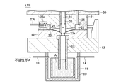
- FIG. 1 is a schematic view showing a casting apparatus according to an embodiment.
- the casting apparatus has a pressurizing chamber (crucible) 10 for pressurizing the molten metal A.
- a container 11 for holding the molten metal A is provided in the pressurizing chamber 10.
- the upper end opening of the pressurizing chamber 10 is closed by the fixing plate 12, and the inside of the pressurizing chamber 10 is a sealed space.
- a gas supply path 13 and a gas discharge path 14 communicate with the sealed space (pressurizing chamber 10).
- the gas supply path 13 is connected to a pressurization source 16 through a valve 15 and supplies an inert gas into the pressurization chamber 10.
- the gas discharge path 14 opens the pressurizing chamber 10 to the atmosphere via the valve 17.
- a fixed mold 19 is attached to the upper surface of the fixed plate 12.
- a movable mold 21 is mounted on the lower surface of the movable plate 20 configured to be movable upward with respect to the fixed mold 19.
- the fixed mold 19 and the movable mold 21 form a cavity 22 when the mold is closed.
- An opening 23 a is formed in a gate portion communicating with the cavity 22 at the center of the fixed mold 19, and an upper end portion of the stalk 18 is communicated with the opening 23 a.
- a degassing passage 23b for extracting gas from the cavity 22 is connected to the fixed mold 19, and the molten metal A is prevented from entering the degassing passage 23b between the cavity 22 and the degassing passage 23b.
- a chill vent 23c is provided.
- the movable mold 21 is provided with a gate seal pin 24, a center pressure pin 25, and a partial pressure pin 26.
- the gate seal pin 24 is configured to move forward and backward with respect to the opening 23a, and opens and closes the opening 23a.
- the gate seal pin 24 is formed in a substantially rod shape.
- the center pressurizing pin 25 is configured to be movable forward and backward with respect to the hot water puddle 27 communicating with the cavity 22 and pressurizes the cavity 22.
- the center pressurizing pin 25 is formed in a cylindrical shape surrounding the gate seal pin 24.
- the partial pressure pin 26 is configured to move forward and backward with respect to the hot water reservoir 28 communicating with the cavity 22 and pressurizes the cavity 22.
- the partial pressure pin 26 is formed in a substantially rod shape.
- the upper ends of the gate seal pin 24 and the center pressurizing pin 25 are connected to a piston mechanism 29 as a driving means, and are configured to be vertically movable.
- the partial pressurizing pins 26 are configured such that their upper ends are connected to a piston mechanism 30 as drive means, and can be moved up and down.
- the casting apparatus has a vacuum device 32 and a controller 33 connected to the gas vent passage 23 b via a gas vent valve 31.
- the vacuum device 32 discharges gas from the cavity 22 through the gas vent valve 31 and the gas vent passage 23b, and depressurizes the inside of the cavity 22.
- the vacuum device 32 includes a vacuum tank 321, a vacuum pump 322 that evacuates the vacuum tank 321, and a motor 323 that drives the vacuum pump 322.
- the controller 33 pressurizes the inside of the pressurizing chamber 10 by controlling the valve 15 and the pressurizing source 16.
- the controller 33 controls the valve 17 to open the pressurizing chamber 10 to the atmosphere.
- the controller 33 controls the valve 31 and the vacuum device 32 to discharge the gas in the cavity 22 and depressurize the inside of the cavity 22.
- the controller 33 controls the piston mechanism 29 to open and close the opening 23 a by the gate seal pin 24.
- the controller 33 controls the piston mechanisms 29 and 30 to pressurize the cavity 22 by the center pressurizing pin 25 and the partial pressurizing pin 26.
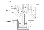
- FIG. 2 is a plan view showing the cavity 22.
- the cavity 22 extends symmetrically in the X direction and the Y direction around the gate seal pin 24 and the center pressurizing pin 25.
- six partial pressure pins 26 are provided near the end of the cavity 22.
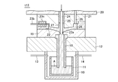
- FIGS. 3A to 3D and FIG. 4 are schematic views of the filling operation.
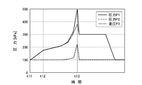
- FIG. 4 shows the pressure P1 applied to the cavity 22 from the pressurizing source 16 over time, the pressure P2 sucking the cavity 22 from the vacuum device 32, and the differential pressure P3 (hereinafter referred to as filling differential pressure) of these pressures P1 and P2. It is a figure which shows a change.
- the filling operation is executed based on the elapsed time. For example, the time for the molten metal A to reach the opening 23a is measured in advance, and the filling operation is executed based on the measured time.
- the controller 33 opens the valve 15 at time t11. Then, the controller 33 supplies an inert gas from the pressurization source 16 to the sealed space of the pressurization chamber 10 via the gas supply path 13. Thereby, as shown in FIG. 4, the pressure P1 applied to the pressurization chamber 10 from the pressurization source 16 rises after the time t11. Therefore, as shown in FIG. 4, the filling differential pressure P3 rises, and the molten metal A rises.
- the controller 33 continues from the pressurizing source 16 through the gas supply path 13 to the pressurizing chamber 10.
- An inert gas is supplied to the enclosed space.
- the controller 33 opens the valve 31 so that the cavity 22 and the vacuum tank 321 communicate with each other. Thereby, the gas in the cavity 22 is discharged to the vacuum tank 321 through the gas vent passage 23b.
- the fact that the molten metal A has reached the opening 23a of the cavity 22 may be detected by a sensor, or the time for the molten metal surface to reach the opening 23a at a predetermined pressure is measured in advance and managed by that time.
- the pressure P1 applied to the cavity 22 from the pressurization source 16 continues to increase after time t12 as shown in FIG.
- the increasing speed of the pressure P1 is not constant.
- the degree of pressure reduction (vacuum) in the mold is increased by the discharge from the cavity 22 by the vacuum device 32. That is, as shown in FIG. 4, the pressure P2 applied to the cavity 22 decreases in the minus direction.
- the filling differential pressure P3 increases as shown in FIG.
- the controller 33 opens the valve 17 to release the pressurizing chamber 10 to the atmosphere, and lowers the molten metal surface of the molten metal A in the stalk 18.
- the controller 33 may press down the center pressurizing pin 25 to pressurize the inside of the cavity 22 and further increase the pressure.
- the gate seal pin 24 and the center pressurizing pin 25 may have an integral structure. In this case, the gate seal pin 24 and the center pressurizing pin 25 are lowered by a single cylinder, and the gate closing and pressurizing are performed in a continuous operation. After the molten metal A in the cavity 22 is solidified, the movable mold 21 is raised and the product is taken out.
- the decompressed cavity 22 is sealed with the gate seal pin 24, the inside of the pressurizing chamber 10 is pressurized, the molten metal A is raised to a position directly below the gate seal pin 24, the gate seal pin 24 is opened, and the pressurization and depressurization are performed.
- the molten metal A flows into the cavity 22 due to the pressure difference, the molten metal A enters the cavity 22 in the form of droplets, and a molten metal and a hot water boundary are generated in the molded product.
- the inside of the pressurizing chamber 10 is pressurized until the molten metal A reaches the opening 23a of the cavity 22 as described above.
- this Embodiment can suppress the splash of the molten metal A, and can suppress generation
- the pressure in the cavity 22 is controlled by the vacuum device 32 and the pressurizing chamber 10. Therefore, compared with the case where a plurality of pressurizing chambers are provided and the pressure in the cavity 22 is controlled, this embodiment can have a simple structure. Further, as compared with the case where the pressure in the cavity 22 is controlled only by the pressurizing chamber 10, the present embodiment can suppress the load applied to the pressurizing chamber 10 and can maintain the airtightness of the pressurizing chamber 10. .
- FIG. 5 shows a pressure P1 applied to the cavity 22 from the pressurization source 16 with the passage of time, a pressure P2 of the cavity 22, and a differential pressure between these pressures P1 and P2 in a comparative example in which the vacuum device 32 is not used together.
- the change of P3 is shown.
- the back pressure in the cavity 22 can be suppressed by the vacuum device 32, the fluidity of the molten metal A in the cavity 22 can be enhanced.
Abstract
Description
29,30…ピストン機構、 31…ガス抜き用弁、 32…真空装置、 33…コントローラ。
A ... Molten metal, 10 ... Pressurizing chamber, 11 ... Container, 12 ... Fixing plate, 13 ... Gas supply passage, 14 ... Gas discharge passage, 15 ... Valve, 16 ... Pressure source, 17 ... Valve, 18 ... Stoke, 19 DESCRIPTION OF SYMBOLS ... Fixed mold, 20 ... Movable plate, 21 ... Movable mold, 22 ... Cavity, 23a ... Opening, 23b ... Gas vent passage, 23c ... Chill vent, 24 ... Gate seal pin, 25 ... Center pressure pin, 26 ... Partial pressure pins, 27, 28 ...
29, 30 ... piston mechanism, 31 ... degassing valve, 32 ... vacuum device, 33 ... controller.
Claims (3)
- 下方に開口を有するキャビティを形成する金型と、
前記金型の下方に配置されて溶湯を収容すると共に溶湯の上部に密閉空間を形成する加圧室と、
上端開口が前記キャビティの開口に連通し下端開口が前記加圧室内の溶湯の内部に浸漬された筒状のストークと、
前記加圧室の密閉空間にガスを供給して前記加圧室内を加圧する加圧手段と、
前記キャビティからガスを排出して、前記キャビティ内を減圧する減圧手段と、
前記加圧室から前記キャビティに溶湯を充填する際、前記溶湯が前記キャビティの開口に達するまで前記加圧手段によって前記加圧室内を加圧し、前記溶湯が前記キャビティの開口に達した後に前記加圧室内の加圧を続行しつつ、前記減圧手段によって前記キャビティ内を減圧する制御装置と
を備えたことを特徴とする鋳造装置。 A mold for forming a cavity having an opening below;
A pressurizing chamber that is disposed below the mold and accommodates the molten metal and forms a sealed space above the molten metal;
A cylindrical stalk in which an upper end opening communicates with the opening of the cavity and a lower end opening is immersed in the molten metal in the pressurized chamber;
Pressurizing means for supplying gas to the sealed space of the pressurizing chamber to pressurize the pressurizing chamber;
A pressure reducing means for discharging gas from the cavity and decompressing the inside of the cavity;
When filling the cavity with the melt from the pressurizing chamber, the pressurizing means pressurizes the pressurizing chamber until the melt reaches the opening of the cavity, and after the molten metal reaches the opening of the cavity, the heating is performed. And a control device for reducing the pressure in the cavity by the pressure reducing means while continuing to pressurize the pressure chamber. - 前記開口に対して進退自在に構成されて前記開口を開閉するゲートシールピンを備え、
前記制御装置は、前記キャビティに前記溶湯が充填された後に前記ゲートシールピンにより前記開口を閉塞する
ことを特徴とする請求項1記載の鋳造装置。 A gate seal pin configured to be movable forward and backward with respect to the opening and opening and closing the opening;
The casting apparatus according to claim 1, wherein the controller closes the opening with the gate seal pin after the molten metal is filled in the cavity. - 前記前記キャビティに連通する湯だまり対して進退自在に構成されて前記キャビティ内に充填された溶湯を加圧する加圧ピンを更に備える
ことを特徴とする請求項1又は2記載の鋳造装置。 3. The casting apparatus according to claim 1, further comprising a pressure pin configured to be capable of moving forward and backward with respect to the puddle communicating with the cavity and pressurizing the molten metal filled in the cavity. 4.
Priority Applications (4)
| Application Number | Priority Date | Filing Date | Title |
|---|---|---|---|
| US14/779,002 US20160045955A1 (en) | 2013-03-21 | 2013-11-29 | Casting device |
| CN201380074842.5A CN105073302B (en) | 2013-03-21 | 2013-11-29 | Casting device |
| KR1020157030092A KR20150131384A (en) | 2013-03-21 | 2013-11-29 | Casting device |
| EP13878814.6A EP2977127A4 (en) | 2013-03-21 | 2013-11-29 | Casting device |
Applications Claiming Priority (2)
| Application Number | Priority Date | Filing Date | Title |
|---|---|---|---|
| JP2013-057572 | 2013-03-21 | ||
| JP2013057572A JP5527451B1 (en) | 2013-03-21 | 2013-03-21 | Casting equipment |
Publications (1)
| Publication Number | Publication Date |
|---|---|
| WO2014147892A1 true WO2014147892A1 (en) | 2014-09-25 |
Family
ID=51175757
Family Applications (1)
| Application Number | Title | Priority Date | Filing Date |
|---|---|---|---|
| PCT/JP2013/082182 WO2014147892A1 (en) | 2013-03-21 | 2013-11-29 | Casting device |
Country Status (6)
| Country | Link |
|---|---|
| US (1) | US20160045955A1 (en) |
| EP (1) | EP2977127A4 (en) |
| JP (1) | JP5527451B1 (en) |
| KR (1) | KR20150131384A (en) |
| CN (1) | CN105073302B (en) |
| WO (1) | WO2014147892A1 (en) |
Cited By (4)
| Publication number | Priority date | Publication date | Assignee | Title |
|---|---|---|---|---|
| US9533397B2 (en) | 2012-06-29 | 2017-01-03 | Saint-Gobain Abrasives, Inc. | Abrasive article and method of forming |
| CN107249784A (en) * | 2015-02-24 | 2017-10-13 | 日产自动车株式会社 | Casting device and casting method |
| EP3238858A4 (en) * | 2014-12-24 | 2017-11-01 | Nissan Motor Co., Ltd. | Low-pressure casting device and low-pressure casting method |
| CN107321959A (en) * | 2017-09-05 | 2017-11-07 | 哈尔滨工业大学 | Large ship rises liquid disabling mechanism with copper alloy propeller counter-pressure casting |
Families Citing this family (13)
| Publication number | Priority date | Publication date | Assignee | Title |
|---|---|---|---|---|
| US10441998B2 (en) | 2014-03-31 | 2019-10-15 | Nissan Motor Co., Ltd. | Casting method and casting device |
| JP6406509B2 (en) * | 2014-12-26 | 2018-10-17 | 日産自動車株式会社 | Casting apparatus and casting method |
| JP6406510B2 (en) * | 2014-12-26 | 2018-10-17 | 日産自動車株式会社 | Casting method and casting apparatus |
| JP6460326B2 (en) * | 2015-02-25 | 2019-01-30 | 日産自動車株式会社 | Casting apparatus and casting method |
| JP6489500B2 (en) * | 2015-02-26 | 2019-03-27 | 日産自動車株式会社 | Casting apparatus and casting method |
| CN105499513A (en) * | 2015-12-23 | 2016-04-20 | 哈尔滨工业大学 | Device for manufacturing automobile aluminum alloy wheel hubs through liquid filling, local pressurizing and feeding and method thereof |
| CN107639221A (en) * | 2017-08-22 | 2018-01-30 | 北京北方恒利科技发展有限公司 | A kind of casting method of bimetallic cylinder |
| CN108311668A (en) * | 2018-03-13 | 2018-07-24 | 中信戴卡股份有限公司 | A kind of aluminum alloy low-pressure casting device and technique |
| CN108580843A (en) * | 2018-03-13 | 2018-09-28 | 中信戴卡股份有限公司 | A kind of aluminum vehicle wheel continuous casting continuous forging forming technology |
| CN109047721B (en) * | 2018-10-18 | 2020-06-05 | 四川省犍为恒益铝业有限公司 | Low-pressure casting die for vehicle box body |
| IT201900018053A1 (en) | 2019-10-07 | 2021-04-07 | Euromac Srl | Apparatus and procedure for the semi-solid state casting and molding of objects in brass, bronze, aluminum alloys, magnesium and light alloys and the like. |
| WO2022112611A1 (en) * | 2020-11-30 | 2022-06-02 | Kurtz Gmbh & Co. Kg | Mold, apparatus and method for low pressure casting |
| KR102409575B1 (en) * | 2021-12-20 | 2022-06-22 | (주)서영 | Vacuum module device for improving casting quality |
Citations (4)
| Publication number | Priority date | Publication date | Assignee | Title |
|---|---|---|---|---|
| JPH05146864A (en) | 1991-11-27 | 1993-06-15 | Toyota Motor Corp | Casting device |
| JPH06264157A (en) * | 1993-03-09 | 1994-09-20 | Hitachi Metals Ltd | Method for casting aluminum alloy and aluminum alloy parts |
| JP2007253168A (en) * | 2006-03-20 | 2007-10-04 | Kosei Aluminum Co Ltd | Vertical type casting apparatus and vertical type casting method |
| JP4897734B2 (en) * | 2008-04-17 | 2012-03-14 | 谷田合金株式会社 | Differential pressure casting equipment |
Family Cites Families (9)
| Publication number | Priority date | Publication date | Assignee | Title |
|---|---|---|---|---|
| FR2583321B1 (en) * | 1985-06-18 | 1987-09-18 | Etude Dev Metallurg | LOW ISOSTATIC PRESSURE CASTING PROCESS AND MACHINE FOR ITS IMPLEMENTATION |
| WO1993007977A1 (en) * | 1991-10-25 | 1993-04-29 | Toyota Jidosha Kabushiki Kaisha | Device and method of vacuum casting |
| JP3097400B2 (en) * | 1993-07-20 | 2000-10-10 | トヨタ自動車株式会社 | Vacuum casting and its equipment |
| JP3147285B2 (en) * | 1995-07-07 | 2001-03-19 | 新東工業株式会社 | Low pressure casting equipment |
| DE19943153C1 (en) * | 1998-03-19 | 2001-01-25 | Gut Gieserei Umwelt Technik Gm | Apparatus for vacuum or pressure casting workpieces comprises a closing device and a pressure producing device formed as a one-piece piston arranged above a riser pipe |
| US6742568B2 (en) * | 2001-05-29 | 2004-06-01 | Alcoa Inc. | Casting apparatus including a gas driven molten metal injector and method |
| ITPD20020167A1 (en) * | 2002-06-21 | 2003-12-22 | Bbs Riva Spa | EQUIPMENT FOR MAKING ALUMINUM OBJECTS, ALUMINUM ALLOYS, LIGHT AND SIMILAR ALLOYS, AND PROCEDURE IMPLEMENTED BY THAT EQUIPMENT |
| US20070215308A1 (en) * | 2004-05-18 | 2007-09-20 | Nagayoshi Matsubara | Vertical Casting Apparatus and Vertical Casting Method |
| ITTO20070934A1 (en) * | 2007-12-21 | 2009-06-22 | Solmar S A S Di Luisa Maria Ma | EQUIPMENT FOR THE MANUFACTURE OF METAL ARTICLES, IN PARTICULAR OF LIGHT ALLOY. |
-
2013
- 2013-03-21 JP JP2013057572A patent/JP5527451B1/en active Active
- 2013-11-29 US US14/779,002 patent/US20160045955A1/en not_active Abandoned
- 2013-11-29 CN CN201380074842.5A patent/CN105073302B/en active Active
- 2013-11-29 EP EP13878814.6A patent/EP2977127A4/en not_active Withdrawn
- 2013-11-29 WO PCT/JP2013/082182 patent/WO2014147892A1/en active Application Filing
- 2013-11-29 KR KR1020157030092A patent/KR20150131384A/en not_active Application Discontinuation
Patent Citations (4)
| Publication number | Priority date | Publication date | Assignee | Title |
|---|---|---|---|---|
| JPH05146864A (en) | 1991-11-27 | 1993-06-15 | Toyota Motor Corp | Casting device |
| JPH06264157A (en) * | 1993-03-09 | 1994-09-20 | Hitachi Metals Ltd | Method for casting aluminum alloy and aluminum alloy parts |
| JP2007253168A (en) * | 2006-03-20 | 2007-10-04 | Kosei Aluminum Co Ltd | Vertical type casting apparatus and vertical type casting method |
| JP4897734B2 (en) * | 2008-04-17 | 2012-03-14 | 谷田合金株式会社 | Differential pressure casting equipment |
Non-Patent Citations (1)
| Title |
|---|
| See also references of EP2977127A4 * |
Cited By (10)
| Publication number | Priority date | Publication date | Assignee | Title |
|---|---|---|---|---|
| US9533397B2 (en) | 2012-06-29 | 2017-01-03 | Saint-Gobain Abrasives, Inc. | Abrasive article and method of forming |
| EP3238858A4 (en) * | 2014-12-24 | 2017-11-01 | Nissan Motor Co., Ltd. | Low-pressure casting device and low-pressure casting method |
| US10272488B2 (en) | 2014-12-24 | 2019-04-30 | Nissan Motor Co., Ltd. | Low-pressure casting device and low-pressure casting method |
| CN107249784A (en) * | 2015-02-24 | 2017-10-13 | 日产自动车株式会社 | Casting device and casting method |
| JPWO2016135843A1 (en) * | 2015-02-24 | 2017-11-24 | 日産自動車株式会社 | Casting apparatus and casting method |
| US20180029114A1 (en) * | 2015-02-24 | 2018-02-01 | Nissan Motor Co., Ltd. | Casting Device and Casting Method |
| EP3263247A4 (en) * | 2015-02-24 | 2018-05-16 | Nissan Motor Co., Ltd. | Casting device and casting method |
| US10286449B2 (en) * | 2015-02-24 | 2019-05-14 | Nissan Motor Co., Ltd. | Casting device and casting method |
| CN107321959A (en) * | 2017-09-05 | 2017-11-07 | 哈尔滨工业大学 | Large ship rises liquid disabling mechanism with copper alloy propeller counter-pressure casting |
| CN107321959B (en) * | 2017-09-05 | 2019-04-16 | 哈尔滨工业大学 | Large ship rises liquid disabling mechanism with copper alloy propeller counter-pressure casting |
Also Published As
| Publication number | Publication date |
|---|---|
| EP2977127A4 (en) | 2016-04-06 |
| CN105073302B (en) | 2017-08-08 |
| CN105073302A (en) | 2015-11-18 |
| EP2977127A1 (en) | 2016-01-27 |
| JP2014180696A (en) | 2014-09-29 |
| JP5527451B1 (en) | 2014-06-18 |
| US20160045955A1 (en) | 2016-02-18 |
| KR20150131384A (en) | 2015-11-24 |
Similar Documents
| Publication | Publication Date | Title |
|---|---|---|
| JP5527451B1 (en) | Casting equipment | |
| CN106975738B (en) | Vacuum die casting equipment and high vacuum die casting method | |
| EP3263247B1 (en) | Casting device and casting method | |
| KR101555376B1 (en) | Casting apparatus | |
| EP3127633B1 (en) | Casting method and casting device | |
| CN110958921A (en) | Method and apparatus for countergravity mold filling | |
| JP2007253168A (en) | Vertical type casting apparatus and vertical type casting method | |
| JP2016043356A (en) | Casting apparatus | |
| JP2012148319A (en) | Apparatus and method for die casting | |
| JP7172765B2 (en) | Casting equipment and casting method | |
| JP6489500B2 (en) | Casting apparatus and casting method | |
| KR101870591B1 (en) | Low-pressure casting method and low-pressure casting apparatus | |
| JP6406509B2 (en) | Casting apparatus and casting method | |
| JP2871358B2 (en) | Casting equipment | |
| JP6183272B2 (en) | Casting apparatus and casting method | |
| JP2016215243A (en) | Molten metal filling control method of casting device | |
| JPH0957422A (en) | Reduced pressure casting method | |
| JP2008044008A (en) | Low-pressure casting apparatus, and inert gas filling method | |
| JPH05146865A (en) | Casting device | |
| JP6268557B2 (en) | Casting method and casting apparatus | |
| JP2014136252A (en) | Casting apparatus | |
| US20130248134A1 (en) | Method and Apparatus for Casting | |
| JP6331643B2 (en) | Low pressure casting equipment | |
| JP2008264796A (en) | Vertical casting apparatus and vertical casting method | |
| JP2016155152A (en) | Casting device and casting method |
Legal Events
| Date | Code | Title | Description |
|---|---|---|---|
| WWE | Wipo information: entry into national phase |
Ref document number: 201380074842.5 Country of ref document: CN |
|
| 121 | Ep: the epo has been informed by wipo that ep was designated in this application |
Ref document number: 13878814 Country of ref document: EP Kind code of ref document: A1 |
|
| WWE | Wipo information: entry into national phase |
Ref document number: 2013878814 Country of ref document: EP |
|
| NENP | Non-entry into the national phase |
Ref country code: DE |
|
| WWE | Wipo information: entry into national phase |
Ref document number: 14779002 Country of ref document: US |
|
| ENP | Entry into the national phase |
Ref document number: 20157030092 Country of ref document: KR Kind code of ref document: A |