WO2014142321A1 - Fluid-throttling member - Google Patents
Fluid-throttling member Download PDFInfo
- Publication number
- WO2014142321A1 WO2014142321A1 PCT/JP2014/056977 JP2014056977W WO2014142321A1 WO 2014142321 A1 WO2014142321 A1 WO 2014142321A1 JP 2014056977 W JP2014056977 W JP 2014056977W WO 2014142321 A1 WO2014142321 A1 WO 2014142321A1
- Authority
- WO
- WIPO (PCT)
- Prior art keywords
- hole
- fluid
- flow path
- throttle
- wall
- Prior art date
Links
Images

Classifications
-
- F—MECHANICAL ENGINEERING; LIGHTING; HEATING; WEAPONS; BLASTING
- F15—FLUID-PRESSURE ACTUATORS; HYDRAULICS OR PNEUMATICS IN GENERAL
- F15D—FLUID DYNAMICS, i.e. METHODS OR MEANS FOR INFLUENCING THE FLOW OF GASES OR LIQUIDS
- F15D1/00—Influencing flow of fluids
- F15D1/02—Influencing flow of fluids in pipes or conduits
- F15D1/025—Influencing flow of fluids in pipes or conduits by means of orifice or throttle elements
-
- F—MECHANICAL ENGINEERING; LIGHTING; HEATING; WEAPONS; BLASTING
- F16—ENGINEERING ELEMENTS AND UNITS; GENERAL MEASURES FOR PRODUCING AND MAINTAINING EFFECTIVE FUNCTIONING OF MACHINES OR INSTALLATIONS; THERMAL INSULATION IN GENERAL
- F16L—PIPES; JOINTS OR FITTINGS FOR PIPES; SUPPORTS FOR PIPES, CABLES OR PROTECTIVE TUBING; MEANS FOR THERMAL INSULATION IN GENERAL
- F16L55/00—Devices or appurtenances for use in, or in connection with, pipes or pipe systems
- F16L55/02—Energy absorbers; Noise absorbers
- F16L55/027—Throttle passages
- F16L55/02754—Throttle passages using a central core throttling the passage
Definitions
- the present invention relates to a fluid throttle member that throttles the flow of fluid.
- JP 2004-340241A as a fluid restricting member for restricting the flow of fluid is provided with a radial air bearing as a flow path member that supports the rotating shaft by the air supplied to the gap between the rotating shaft and the support surface.
- An orifice pin for restricting the flow of the gas is disclosed.
- This orifice pin is a cylindrical member that is inserted into the orifice pin insertion hole of the radial air bearing. Inside the orifice pin, an ejection hole is formed as a throttle hole for restricting the flow of air supplied between the rotating shaft and the support surface.
- the orifice pin is fixed by press-fitting the outer periphery thereof into the orifice pin insertion hole.
- the ejection hole is deformed by the stress generated when it is press-fitted into the orifice pin insertion hole. For this reason, there is a possibility that the flow passage area of the ejection hole may vary due to the dimensional error of the scallop that is an error of the press-fitting allowance.
- An object of the present invention is to suppress variation in the flow path area of the throttle hole of the fluid throttle member.
- the fluid throttle member that is inserted into the flow path hole of the flow path member to restrict the flow of the fluid is fixed to the inner wall of the flow path hole, and the flow path through which the fluid flows is defined. And a throttle hole that is offset in the axial direction of the flow path hole with respect to the fixed part and restricts the flow of fluid.
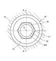
- FIG. 1 is a plan view of a fluid throttle member according to the first embodiment of the present invention.
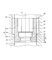
- FIG. 2 is a sectional view taken along line II-II in FIG.
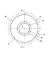
- FIG. 3 is a plan view of a fluid throttle member according to the second embodiment of the present invention.
- 4 is a cross-sectional view taken along line IV-IV in FIG.
- FIG 1 and 2 show a fluid throttle member 20 interposed in a housing 10 as a flow path member of a hydraulic pump as a fluid pressure pump.
- the fluid throttle member 20 provides resistance to the flow of hydraulic oil in the hydraulic pump.
- the fluid throttle member 20 is selected to meet the product specifications when the hydraulic pump is manufactured, and is assembled to the housing 10.
- a flow path hole 11 that forms an oil passage through which hydraulic oil flows is formed.
- the channel hole 11 is a through hole having a circular channel cross section centered on the axis O.
- the inner wall 12 of the channel hole 11 includes a screw part 13 extending from one end of the channel hole 11, a small cylindrical inner wall part 15 having a smaller opening diameter than the screw part 13, a screw part 13, and a small diameter inner wall. And an annular stepped portion 14 formed between the portion 15 and the portion 15.
- the fluid throttle member 20 is formed in a cylindrical shape that is inserted into the flow path hole 11.
- the fluid throttle member 20 includes a fixed portion 29 that is fixed to the inner wall 12 of the flow path hole 11, a small diameter cylindrical portion 23 that has a smaller outer diameter than the fixed portion 29, and a fixed portion 29 and a small diameter cylinder. And an annular stepped portion 22 formed between the portion 23.
- a screw portion 21 is formed on the outer periphery of the fixing portion 29.
- the fluid throttle member 20 is fixed to the housing 10 by screwing the screw portion 21 into the screw portion 13 of the flow path hole 11.
- the tool engaging hole 26 having a hexagonal cross-sectional shape is formed in the fixing portion 29.
- the fluid throttle member 20 is screwed into the screw portion 13 with a predetermined tightening torque, and the stepped portion 22 contacts the stepped portion 14 of the flow path hole 11. Thereby, the fluid throttle member 20 is held at a predetermined position in the axial direction.
- axial direction means a direction in which the axis O of the flow path hole 11 extends.
- the flow path hole 11 may be formed in a straight shape in which the stepped portion 14 is not provided.
- the fluid throttle member 20 may be configured such that axial positioning is performed by contacting a member or the like provided adjacent to the housing 10.
- the small diameter cylindrical portion 23 is formed continuously with the fixed portion 29.
- a throttle hole 25 is formed in the middle of the small diameter cylindrical portion 23.
- the throttle hole 25 has a circular channel cross section and is formed around the axis O.
- the throttle hole 25 constitutes an orifice as a throttle having a predetermined flow path area.
- the throttle hole 25 gives resistance to the flow of the hydraulic oil passing through the throttle hole 25 and adjusts the pressure difference between the hydraulic oil before and after the throttle hole 25.
- annular tapered portions 25A and 25B are formed so as to sandwich the throttle hole 25 therebetween.
- the tapered portions 25 ⁇ / b> A and 25 ⁇ / b> B are formed in a truncated cone shape that is inclined with respect to the axis O, and guides the hydraulic oil so that it flows smoothly before and after the throttle hole 25.
- the small diameter cylindrical portion 23 extends in the axial direction with respect to the fixed portion 29.
- the throttle hole 25 is offset in the axial direction with respect to the fixed portion 29.
- the relay hole 27 is formed across the fixed portion 29 and the small diameter cylindrical portion 23.
- the relay hole 27 has a circular channel cross section, and is formed around the axis O.
- the flow path of the fluid throttle member 20 includes a tool engagement hole 26, a relay hole 27, a tapered portion 25A, a throttle hole 25, and a tapered portion 25B.
- the screw portion 21 of the fixing portion 29 is screwed into the screw portion 13 of the flow passage hole 11, and the stepped portion 22 of the fixing portion 29 is stepped of the flow passage hole 11. It is pressed against the part 14. At this time, a compressive load is applied to the fixed portion 29 of the fluid throttle member 20 from the stepped portion 14 of the flow path hole 11. Therefore, the fixing portion 29 is deformed in a direction in which the inner and outer diameters become smaller. At this time, the throttle hole 25 is separated from the fixed portion 29 in the axial direction. Therefore, deformation of the throttle hole 25 due to the stress generated in the fixed portion 29 is suppressed.
- the small diameter cylindrical portion 23 has a smaller outer diameter than the fixed portion 29. Thereby, a gap 18 is defined between the outer periphery of the small diameter cylindrical portion 23 and the inner wall 12 of the flow path hole 11. Therefore, when the fixing portion 29 is fixed to the inner wall 12 of the flow path hole 11, the outer periphery of the small diameter cylindrical portion 23 does not come into contact with the inner wall 12 of the flow path hole 11. Therefore, it is possible to avoid deformation of the throttle hole 25 by receiving force directly from the inner wall 12 of the flow path hole 11.
- the throttle hole 25 can impart a set resistance to the flow of hydraulic oil when the hydraulic pump is operated, so that the expected performance of the hydraulic pump can be ensured.
- the fluid throttle member 20 is fixed to the inner wall 12 of the flow path hole 11 and includes a fixed portion 29 that defines a flow path through which the fluid flows, and a throttle hole 25 that throttles the flow of the fluid.
- the fixed portion 29 and the throttle hole 25 are offset in the axial direction of the flow path hole 11.
- the fixing portion 29 and the throttle hole 25 formed in the fluid throttle member 20 are separated from each other in the axial direction of the flow path hole 11. Therefore, when the fixing portion 29 is fixed to the inner wall 12 of the flow path hole 11, the deformation of the throttle hole 25 due to the stress generated in the fixing portion 29 is suppressed. Therefore, the variation in the cross-sectional area of the throttle hole 25 can be suppressed.
- the fluid throttle member 20 includes a small-diameter cylindrical portion 23 that is connected to the fixed portion 29 and has a smaller outer diameter than the fixed portion 29.
- the throttle hole 25 is formed in the small diameter cylindrical portion 23.
- the small diameter cylindrical portion 23 is disposed with a gap 18 with respect to the inner wall 12 of the flow path hole 11.
- the fixing portion 29 is screwed into the screw portion 13 formed on the inner wall 12 of the flow path hole 11.
- a fluid throttle member 40 according to a second embodiment of the present invention will be described with reference to FIGS.
- the fixed portion 29 is configured to be screwed into the screw portion 13 of the flow path hole 11.
- the second embodiment is different from the first embodiment in that the fixing portion 49 is press-fitted into the inner wall 32 of the flow path hole 31.
- a flow passage hole 31 that forms an oil passage through which hydraulic oil flows is formed in the housing 30 as a flow passage member of the hydraulic pump.
- the channel hole 31 is a through hole having a circular channel cross section centered on the axis O.
- the inner wall 32 of the flow passage hole 31 includes a cylindrical surface-shaped large-diameter inner wall portion 33 having a predetermined opening diameter, and a cylindrical-surface-shaped small-diameter inner wall portion 35 having an opening diameter smaller than that of the large-diameter inner wall portion 33. And an annular stepped portion 34 formed between the large-diameter inner wall portion 33 and the small-diameter inner wall portion 35.
- the fluid throttle member 40 is formed in a cylindrical shape that is inserted into the flow path hole 31.
- the fluid throttle member 40 includes a fixed portion 49 that is fixed to the inner wall 32 of the flow path hole 31, a small diameter cylindrical portion 43 that has a smaller outer diameter than the fixed portion 49, and a fixed portion 49 and a small diameter cylindrical portion 43. And an annular stepped portion 42 formed between the two.
- a fitting surface 41 is formed which fits into the large-diameter inner wall portion 33 of the flow path hole 31 in a relation of squeeze.
- the fluid throttle member 40 is fixed to the housing 30 by the fitting surface 41 being press-fitted into the large-diameter inner wall portion 33 of the flow path hole 31.
- the fluid throttle member 40 When assembling the fluid throttle member 40, the fluid throttle member 40 is inserted into the flow path hole 31 with a predetermined load, and the stepped portion 42 contacts the stepped portion 34 of the flow path hole 31. Thereby, the fluid throttle member 40 is held at a predetermined position in the axial direction.
- the flow path hole 31 may be formed in a straight shape in which the stepped portion 34 is not provided.
- the fluid throttle member 40 may be configured such that axial positioning is performed by contacting a member or the like provided adjacent to the housing 30.
- the small diameter cylindrical portion 43 is formed continuously with the fixed portion 49.
- a throttle hole 45 is formed in the middle of the small diameter cylindrical portion 43.
- the throttle hole 45 has a circular channel cross section and is formed around the axis O.
- the throttle hole 45 constitutes an orifice as a throttle having a predetermined flow path area.
- the throttle hole 45 provides resistance to the flow of hydraulic oil passing through the throttle hole 45 and adjusts the pressure difference between the hydraulic oil before and after the throttle hole 45.
- annular tapered portions 45A and 45B are formed so as to sandwich the throttle hole 45 therebetween.
- the tapered portions 45A and 45B are formed in a truncated cone shape that is inclined with respect to the axis O.
- the tapered portions 45 ⁇ / b> A and 45 ⁇ / b> B guide the hydraulic oil so that it flows smoothly before and after the throttle hole 45.
- the small diameter cylindrical portion 43 extends in the axial direction with respect to the fixed portion 49.
- the throttle hole 45 is offset in the axial direction with respect to the fixed portion 49.
- the through hole 46 is formed across the fixed portion 49 and the small diameter cylindrical portion 43.
- the through hole 46 has a circular channel cross section and is formed around the axis O.
- the flow path of the fluid throttle member 40 includes a through hole 46, a tapered portion 45A, a throttle hole 45, and a tapered portion 45B.
- the fluid throttle member 40 When the fluid throttle member 40 is assembled to the housing 30, the fluid throttle member 40 is press-fitted into the flow path hole 31 of the housing 30. At this time, a compressive load is applied to the fixed portion 49 of the fluid throttle member 40 from the inner wall 32 of the flow path hole 31. Therefore, the fixed part 49 is deformed so that the inner and outer diameters thereof are reduced. At this time, the throttle hole 45 is separated from the fixed portion 49 in the axial direction. Therefore, deformation of the throttle hole 45 due to stress generated in the fixed portion 49 can be suppressed.
- the small diameter cylindrical portion 43 has a smaller outer diameter than the fixed portion 49. Thereby, a gap 38 is defined between the outer diameter of the small diameter cylindrical portion 43 and the inner wall 32 of the flow path hole 31. Therefore, the outer periphery of the small diameter cylindrical portion 43 does not contact the inner wall 32 of the flow path hole 31. Therefore, it is possible to avoid deformation of the throttle hole 45 by receiving force directly from the inner wall 32 of the flow path hole 31.
- the throttle hole 45 can impart a set resistance to the flow of hydraulic oil when the hydraulic pump is operated, so that the expected performance of the hydraulic pump can be ensured.
- a thread portion is formed in the through hole 46 of the fixing portion 49, and the fluid throttle member 40 is connected to the flow path hole via a tool screwed into the screw portion. It is good also as a structure extracted from 31.
- the fluid throttle member 40 has a configuration in which the fixed portion 49 is press-fitted into the inner wall 32 of the flow path hole 31 and the throttle hole 45 is offset in the axial direction with respect to the fixed portion 49.
- the fluid throttle member is provided in the hydraulic pump, but is not limited thereto, and may be provided in another machine or facility.
- hydraulic oil is used as the fluid flowing through the fluid throttle member.
- a hydraulic fluid such as a water-soluble alternative liquid or gas may be used.
Abstract
Description
まず、図1及び図2を参照して、第一の実施の形態に係る流体絞り部材20について説明する。 (First embodiment)
First, the
次に、図3及び図4を参照して、本発明の第二の実施の形態に係る流体絞り部材40について説明する。第一の実施の形態に係る流体絞り部材20では、固定部29が流路孔11のネジ部13に螺合する構成であった。第二の実施の形態は、固定部49が流路孔31の内壁32に圧入される構成である点で、第一の実施の形態とは相違する。 (Second embodiment)
Next, a
Claims (4)
- 流路部材の流路孔に挿入されて流体の流れを絞る流体絞り部材であって、
前記流路孔の内壁に固定され流体が流れる流路が画成される固定部と、
前記固定部に対して前記流路孔の軸方向にオフセットされて設けられ流体の流れを絞る絞り孔と、を備える流体絞り部材。 A fluid throttle member that is inserted into a channel hole of a channel member to throttle the flow of fluid,
A fixed portion that is fixed to the inner wall of the flow path hole and that defines a flow path through which fluid flows;
A fluid throttle member comprising: a throttle hole that is offset in the axial direction of the flow path hole with respect to the fixed portion and throttles the flow of fluid. - 請求項1に記載の流体絞り部材であって、
前記固定部に連設され、当該固定部と比較して小さい外径を有する小径筒部をさらに備え、
前記絞り孔は前記小径筒部に形成され、
前記小径筒部は、前記流路孔の内壁に対して間隙をあけて配設される流体絞り部材。 The fluid throttle member according to claim 1,
Further provided with a small-diameter cylindrical portion that is connected to the fixed portion and has a smaller outer diameter than the fixed portion,
The throttle hole is formed in the small diameter cylindrical portion,
The small diameter cylindrical portion is a fluid throttle member disposed with a gap with respect to the inner wall of the flow path hole. - 請求項1に記載の流体絞り部材であって、
前記固定部は前記流路孔の内壁に形成されたネジ部に螺合する流体絞り部材。 The fluid throttle member according to claim 1,
The fixed portion is a fluid throttle member that is screwed into a screw portion formed on an inner wall of the flow path hole. - 請求項1に記載の流体絞り部材であって、
前記固定部は前記流路孔の内壁に圧入される流体絞り部材。 The fluid throttle member according to claim 1,
The fixed portion is a fluid throttle member that is press-fitted into the inner wall of the flow path hole.
Priority Applications (3)
| Application Number | Priority Date | Filing Date | Title |
|---|---|---|---|
| US14/773,794 US20160017903A1 (en) | 2013-03-15 | 2014-03-14 | Fluid throttle member |
| CN201480012676.0A CN105074311A (en) | 2013-03-15 | 2014-03-14 | Fluid-throttling member |
| EP14762360.7A EP2975313A4 (en) | 2013-03-15 | 2014-03-14 | Fluid-throttling member |
Applications Claiming Priority (2)
| Application Number | Priority Date | Filing Date | Title |
|---|---|---|---|
| JP2013-053333 | 2013-03-15 | ||
| JP2013053333A JP2014178012A (en) | 2013-03-15 | 2013-03-15 | Fluid orifice member |
Publications (1)
| Publication Number | Publication Date |
|---|---|
| WO2014142321A1 true WO2014142321A1 (en) | 2014-09-18 |
Family
ID=51536968
Family Applications (1)
| Application Number | Title | Priority Date | Filing Date |
|---|---|---|---|
| PCT/JP2014/056977 WO2014142321A1 (en) | 2013-03-15 | 2014-03-14 | Fluid-throttling member |
Country Status (5)
| Country | Link |
|---|---|
| US (1) | US20160017903A1 (en) |
| EP (1) | EP2975313A4 (en) |
| JP (1) | JP2014178012A (en) |
| CN (1) | CN105074311A (en) |
| WO (1) | WO2014142321A1 (en) |
Cited By (1)
| Publication number | Priority date | Publication date | Assignee | Title |
|---|---|---|---|---|
| GB2522540A (en) * | 2014-01-14 | 2015-07-29 | Caterpillar Inc | Asymmetrical orifice for bypass control |
Families Citing this family (4)
| Publication number | Priority date | Publication date | Assignee | Title |
|---|---|---|---|---|
| FR3061934B1 (en) * | 2017-01-19 | 2019-06-07 | Robert Bosch Gmbh | HIGH PRESSURE FUEL INJECTION SYSTEM RAMP |
| CA3047289A1 (en) | 2019-06-19 | 2020-12-19 | Slurryflo Valve Corporation | Flow centralizer for valve assembly |
| CA3047469A1 (en) | 2019-06-20 | 2020-12-20 | Slurryflo Valve Corporation | Gate valve |
| CN112683356A (en) * | 2021-01-21 | 2021-04-20 | 上海凯泉泵业(集团)有限公司 | Annular throttling device |
Citations (8)
| Publication number | Priority date | Publication date | Assignee | Title |
|---|---|---|---|---|
| JPS5120123A (en) * | 1974-07-01 | 1976-02-18 | Hydrotech Int Inc | |
| JPS542230U (en) * | 1977-06-08 | 1979-01-09 | ||
| JPS62181791U (en) * | 1986-05-10 | 1987-11-18 | ||
| FR2845129A1 (en) * | 2002-09-30 | 2004-04-02 | Delphi Tech Inc | An insert of type flow valve for attenuating the pressure waves, and common rail equipped with such insert for use in an injection system of diesel type engine |
| JP2004144251A (en) * | 2002-10-25 | 2004-05-20 | Fuji Bc Engineering Co Ltd | Fluid equipment, and orifice hole size changing method for the same |
| JP2004340241A (en) | 2003-05-15 | 2004-12-02 | Disco Abrasive Syst Ltd | Air spindle |
| JP2007247641A (en) * | 2006-02-20 | 2007-09-27 | Denso Corp | Common rail |
| JP2008031944A (en) * | 2006-07-31 | 2008-02-14 | Denso Corp | Common rail and method for manufacturing bushing for common rail |
Family Cites Families (11)
| Publication number | Priority date | Publication date | Assignee | Title |
|---|---|---|---|---|
| US3072261A (en) * | 1960-04-04 | 1963-01-08 | Holley Carburetor Co | Sediment trapping hydraulic restriction |
| JPH06307568A (en) * | 1993-04-26 | 1994-11-01 | Tokimec Inc | Control valve, and orifice and check valve mounted on connection port thereof |
| JPH09287689A (en) * | 1996-04-22 | 1997-11-04 | Hitachi Constr Mach Co Ltd | Flow passage structure |
| DE29710159U1 (en) * | 1997-06-11 | 1998-10-08 | Bosch Gmbh Robert | Throttle element |
| JP3432460B2 (en) * | 1999-08-10 | 2003-08-04 | 株式会社アメニティ | Flow controller |
| US7942139B1 (en) * | 2005-06-08 | 2011-05-17 | Mile Edge Plus Inc | Ring insert for an air intake conduit for an internal combustion engine |
| JP4442567B2 (en) * | 2006-01-20 | 2010-03-31 | 株式会社デンソー | Common rail |
| US7516734B2 (en) * | 2006-01-20 | 2009-04-14 | Denso Corporation | Common rail having orifice |
| JP4798247B2 (en) * | 2009-03-31 | 2011-10-19 | 株式会社デンソー | connector |
| CN101832340B (en) * | 2010-01-26 | 2011-11-16 | 西安交通大学 | Annular slit restrictor |
| CN202442554U (en) * | 2011-10-16 | 2012-09-19 | 新昌县丰亿电器有限公司 | Bidirectional throttle valve |
-
2013
- 2013-03-15 JP JP2013053333A patent/JP2014178012A/en active Pending
-
2014
- 2014-03-14 CN CN201480012676.0A patent/CN105074311A/en active Pending
- 2014-03-14 US US14/773,794 patent/US20160017903A1/en not_active Abandoned
- 2014-03-14 WO PCT/JP2014/056977 patent/WO2014142321A1/en active Application Filing
- 2014-03-14 EP EP14762360.7A patent/EP2975313A4/en not_active Withdrawn
Patent Citations (8)
| Publication number | Priority date | Publication date | Assignee | Title |
|---|---|---|---|---|
| JPS5120123A (en) * | 1974-07-01 | 1976-02-18 | Hydrotech Int Inc | |
| JPS542230U (en) * | 1977-06-08 | 1979-01-09 | ||
| JPS62181791U (en) * | 1986-05-10 | 1987-11-18 | ||
| FR2845129A1 (en) * | 2002-09-30 | 2004-04-02 | Delphi Tech Inc | An insert of type flow valve for attenuating the pressure waves, and common rail equipped with such insert for use in an injection system of diesel type engine |
| JP2004144251A (en) * | 2002-10-25 | 2004-05-20 | Fuji Bc Engineering Co Ltd | Fluid equipment, and orifice hole size changing method for the same |
| JP2004340241A (en) | 2003-05-15 | 2004-12-02 | Disco Abrasive Syst Ltd | Air spindle |
| JP2007247641A (en) * | 2006-02-20 | 2007-09-27 | Denso Corp | Common rail |
| JP2008031944A (en) * | 2006-07-31 | 2008-02-14 | Denso Corp | Common rail and method for manufacturing bushing for common rail |
Non-Patent Citations (1)
| Title |
|---|
| See also references of EP2975313A4 * |
Cited By (2)
| Publication number | Priority date | Publication date | Assignee | Title |
|---|---|---|---|---|
| GB2522540A (en) * | 2014-01-14 | 2015-07-29 | Caterpillar Inc | Asymmetrical orifice for bypass control |
| GB2522540B (en) * | 2014-01-14 | 2020-09-02 | Caterpillar Inc | Asymmetrical orifice for bypass control |
Also Published As
| Publication number | Publication date |
|---|---|
| US20160017903A1 (en) | 2016-01-21 |
| EP2975313A1 (en) | 2016-01-20 |
| CN105074311A (en) | 2015-11-18 |
| EP2975313A4 (en) | 2016-11-09 |
| JP2014178012A (en) | 2014-09-25 |
Similar Documents
| Publication | Publication Date | Title |
|---|---|---|
| WO2014142321A1 (en) | Fluid-throttling member | |
| US9995406B2 (en) | Valve device | |
| JP7242781B2 (en) | Electric valve and refrigeration cycle system | |
| JP5213636B2 (en) | Seal device for joint and fluid joint having the same | |
| JP5369065B2 (en) | Three-way valve | |
| JP2014178012A5 (en) | ||
| JP5982355B2 (en) | Channel seal structure | |
| JP6442723B2 (en) | Sealing structure | |
| US8162582B2 (en) | Threaded connection piece | |
| JP2013068270A (en) | Joint sealing device | |
| JP2013524096A (en) | Valve located in a hole provided in the passage housing | |
| JP2009243522A (en) | Safety valve and sealing structure | |
| EP2447512A1 (en) | Bypass air volume control system for throttle body | |
| JP2013224677A (en) | Pipe joint | |
| JP5369136B2 (en) | Valve seal structure | |
| JP5658194B2 (en) | solenoid valve | |
| JP2009024712A (en) | Sealing device | |
| TWI678492B (en) | Connector | |
| JP5579375B2 (en) | Flare nut | |
| JP6187931B2 (en) | Assembly structure of eye joint, eye bolt and washer | |
| JP5653676B2 (en) | Fluid control valve | |
| WO2021250948A1 (en) | Resin tube connection device | |
| JP5303226B2 (en) | Double seat valve | |
| JP6613667B2 (en) | Spool switching valve device | |
| JP5351534B2 (en) | Valve member |
Legal Events
| Date | Code | Title | Description |
|---|---|---|---|
| WWE | Wipo information: entry into national phase |
Ref document number: 201480012676.0 Country of ref document: CN |
|
| 121 | Ep: the epo has been informed by wipo that ep was designated in this application |
Ref document number: 14762360 Country of ref document: EP Kind code of ref document: A1 |
|
| DPE2 | Request for preliminary examination filed before expiration of 19th month from priority date (pct application filed from 20040101) | ||
| WWE | Wipo information: entry into national phase |
Ref document number: 14773794 Country of ref document: US |
|
| NENP | Non-entry into the national phase |
Ref country code: DE |
|
| REEP | Request for entry into the european phase |
Ref document number: 2014762360 Country of ref document: EP |
|
| WWE | Wipo information: entry into national phase |
Ref document number: 2014762360 Country of ref document: EP |