JP5982355B2 - Channel seal structure - Google Patents
Channel seal structure Download PDFInfo
- Publication number
- JP5982355B2 JP5982355B2 JP2013269780A JP2013269780A JP5982355B2 JP 5982355 B2 JP5982355 B2 JP 5982355B2 JP 2013269780 A JP2013269780 A JP 2013269780A JP 2013269780 A JP2013269780 A JP 2013269780A JP 5982355 B2 JP5982355 B2 JP 5982355B2
- Authority
- JP
- Japan
- Prior art keywords
- flow path
- seal structure
- main body
- recess
- structure according
- Prior art date
- Legal status (The legal status is an assumption and is not a legal conclusion. Google has not performed a legal analysis and makes no representation as to the accuracy of the status listed.)
- Active
Links
Images


Classifications
-
- F—MECHANICAL ENGINEERING; LIGHTING; HEATING; WEAPONS; BLASTING
- F16—ENGINEERING ELEMENTS AND UNITS; GENERAL MEASURES FOR PRODUCING AND MAINTAINING EFFECTIVE FUNCTIONING OF MACHINES OR INSTALLATIONS; THERMAL INSULATION IN GENERAL
- F16L—PIPES; JOINTS OR FITTINGS FOR PIPES; SUPPORTS FOR PIPES, CABLES OR PROTECTIVE TUBING; MEANS FOR THERMAL INSULATION IN GENERAL
- F16L15/00—Screw-threaded joints; Forms of screw-threads for such joints
- F16L15/006—Screw-threaded joints; Forms of screw-threads for such joints with straight threads
- F16L15/008—Screw-threaded joints; Forms of screw-threads for such joints with straight threads with sealing rings
-
- G—PHYSICS
- G01—MEASURING; TESTING
- G01F—MEASURING VOLUME, VOLUME FLOW, MASS FLOW OR LIQUID LEVEL; METERING BY VOLUME
- G01F1/00—Measuring the volume flow or mass flow of fluid or fluent solid material wherein the fluid passes through a meter in a continuous flow
- G01F1/05—Measuring the volume flow or mass flow of fluid or fluent solid material wherein the fluid passes through a meter in a continuous flow by using mechanical effects
- G01F1/34—Measuring the volume flow or mass flow of fluid or fluent solid material wherein the fluid passes through a meter in a continuous flow by using mechanical effects by measuring pressure or differential pressure
- G01F1/36—Measuring the volume flow or mass flow of fluid or fluent solid material wherein the fluid passes through a meter in a continuous flow by using mechanical effects by measuring pressure or differential pressure the pressure or differential pressure being created by the use of flow constriction
- G01F1/40—Details of construction of the flow constriction devices
- G01F1/42—Orifices or nozzles
-
- F—MECHANICAL ENGINEERING; LIGHTING; HEATING; WEAPONS; BLASTING
- F16—ENGINEERING ELEMENTS AND UNITS; GENERAL MEASURES FOR PRODUCING AND MAINTAINING EFFECTIVE FUNCTIONING OF MACHINES OR INSTALLATIONS; THERMAL INSULATION IN GENERAL
- F16L—PIPES; JOINTS OR FITTINGS FOR PIPES; SUPPORTS FOR PIPES, CABLES OR PROTECTIVE TUBING; MEANS FOR THERMAL INSULATION IN GENERAL
- F16L55/00—Devices or appurtenances for use in, or in connection with, pipes or pipe systems
- F16L55/02—Energy absorbers; Noise absorbers
- F16L55/027—Throttle passages
-
- G—PHYSICS
- G01—MEASURING; TESTING
- G01F—MEASURING VOLUME, VOLUME FLOW, MASS FLOW OR LIQUID LEVEL; METERING BY VOLUME
- G01F15/00—Details of, or accessories for, apparatus of groups G01F1/00 - G01F13/00 insofar as such details or appliances are not adapted to particular types of such apparatus
- G01F15/005—Valves
-
- G—PHYSICS
- G05—CONTROLLING; REGULATING
- G05D—SYSTEMS FOR CONTROLLING OR REGULATING NON-ELECTRIC VARIABLES
- G05D7/00—Control of flow
- G05D7/06—Control of flow characterised by the use of electric means
- G05D7/0617—Control of flow characterised by the use of electric means specially adapted for fluid materials
- G05D7/0629—Control of flow characterised by the use of electric means specially adapted for fluid materials characterised by the type of regulator means
- G05D7/0635—Control of flow characterised by the use of electric means specially adapted for fluid materials characterised by the type of regulator means by action on throttling means
Description
本発明は、流路シール構造に係り、詳しくは、圧力式流量制御装置等の本体ブロック内の流路にオリフィスプレートやフィルタープレート等の通孔が形成された薄板が介在された流路のシール構造に関する。 The present invention relates to a flow path seal structure, and more specifically, a flow path seal in which a thin plate in which a through hole such as an orifice plate or a filter plate is formed is interposed in a flow path in a main body block of a pressure type flow control device or the like. Concerning structure.
従来、例えば圧力式流量制御装置においては、図8に示すように、本体流路1a、1bが形成された本体ブロック1と、入口側流路2aが形成された入口側ブロック2と、出口側流路3aが形成された出口側ブロック3とを連結することにより、各流路2a、1a、1b、3aを連通させてある。本体流路1a、1bの間に介在された金属ダイヤフラム弁等の弁体4を、本体ブロック1に取り付けられた圧電式アクチュエータ5によって開閉操作できるようになっている(特許文献1参照)。
Conventionally, for example, in a pressure type flow control device, as shown in FIG. 8, a
そして、出口側ブロック3と本体ブロック1との間に、流量制御のためのオリフィスプレート6が固定されたガスケット型オリフィス7を挟み込む構造(特許文献1)や、入口側ブロック2と本体ブロック1との間に、フィルタープレート8が固定されたフィルターガスケット9を挟み込む構造等が知られている(特許文献1〜4等)。
And the structure (patent document 1) which sandwiches the
この種の圧力式流量制御装置10では、オリフィスプレート6の下流側圧力P2と上流側圧力P1との間に(P1/P2)≧約2の所謂臨界膨張条件が保持されていると、オリフィスプレート6のオリフィスを流通するガス流量QがQ=KP1(但しKは定数)の関係となる。
In this type of pressure type
このような関係を利用して、圧力検出器11で検出される圧力P1を制御することにより流量Qを高精度で制御することができ、しかも、弁体4の上流側ガスGoの圧力が大きく変化しても、制御流量値が殆ど変化しないという優れた特性を発揮することができる。
By utilizing such a relationship, the flow rate Q can be controlled with high accuracy by controlling the pressure P 1 detected by the
オリフィスプレートやフィルタープレートは、一般には、オリフィスベースやフィルターベースに溶接されて固定されている。溶接できない焼結フィルタープレートの場合は、フィルターベース等に環状のリップ部を設けておいて、該リップ部を内側に折り曲げて(カシメて)フィルタープレートを固定する方法も知られている(特許文献3等)。或いは、オリフィスベースやフィルターベースを互いに嵌合可能な半割形にして、両者を嵌合する際にそれらの間にオリフィスプレートやフィルタープレートを挟み込む形式のものもある(特許文献1、2、4等)。半割型のものでは、一方の側のオリフィスベース半体にオリフィスプレートやフィルタープレートをレーザー溶接することが一般的である。
In general, the orifice plate and the filter plate are welded and fixed to the orifice base and the filter base. In the case of a sintered filter plate that cannot be welded, a method is also known in which an annular lip is provided on a filter base or the like, and the lip is bent inward (caulking) to fix the filter plate (Patent Literature). 3 etc.). Alternatively, there is a type in which an orifice base and a filter base are halved so that they can be fitted to each other, and when both are fitted, an orifice plate and a filter plate are sandwiched between them (
しかしながら、オリフィスプレートやフィルタープレートを溶接あるいはカシメにより固定するのは、それらのプレート自体が微細(例えば直径3.5mm)であり、溶接加工やカシメ加工が容易ではない。 However, the orifice plate and the filter plate are fixed by welding or caulking because the plates themselves are fine (for example, 3.5 mm in diameter), and welding and caulking are not easy.
また、近年では、装置の小型化・薄型化が急速に進んでおり、従来構造のもの、特に半割型のものは小型化・薄型化に限界があり、それらを適用することが困難となってきていた。 Also, in recent years, downsizing and thinning of devices are rapidly progressing, and the conventional structure, especially the halved type has a limit to downsizing and thinning, making it difficult to apply them. It was coming.
そこで、本発明は、オリフィスプレートやフィルタープレートを母材となるオリフィスベースやフィルターベースに溶接やカシメを行う工程を省略することができるとともに、いっそうの小型化を可能にするシール構造を提供することを主たる目的とする。 Therefore, the present invention provides a seal structure that can omit the process of welding or crimping the orifice plate or filter plate to the orifice base or filter base as a base material and enables further miniaturization. Is the main purpose.
上記目的を達成するため、本発明に係る流路シール構造は、本体流路が形成された本体ブロックと、前記本体ブロックに形成された凹部であって、該凹部の奥底に前記本体流路が開口するとともに、該凹部の内周面に雌螺子が形成された前記凹部と、前記凹部の奥底に当接されて通孔が形成された薄板と、前記薄板に当接するガスケットリングと、前記本体流路と連通可能な内部流路と拡径部とを有し前記ガスケットリングに当接する押え配管と、軸方向に挿通孔を有し該挿通孔を介して前記押え配管に外挿されるとともに前記雌螺子に螺入されて前記拡径部に当接して前記押え配管を押圧する締付螺子と、を備えることを特徴とする。 In order to achieve the above object, a flow path seal structure according to the present invention includes a main body block in which a main body flow path is formed, and a recess formed in the main body block, and the main body flow path is provided at the bottom of the recess. The concave portion formed with an internal thread on the inner peripheral surface of the concave portion, a thin plate in contact with the bottom of the concave portion to form a through hole, a gasket ring in contact with the thin plate, and the main body A holding pipe that has an internal flow path that can communicate with the flow path and a diameter-expanded portion, and that contacts the gasket ring; an insertion hole in the axial direction; and is externally inserted into the holding pipe through the insertion hole; And a fastening screw that is screwed into a female screw and abuts against the enlarged-diameter portion to press the presser pipe.
前記押え配管が前記締付螺子と共回りするのを防止する共回り防止機構を更に備えることが好ましい。 It is preferable to further include a co-rotation preventing mechanism for preventing the presser pipe from co-rotating with the fastening screw.
前記共回り防止機構は、前記拡径部に形成された被係合部と、前記本体ブロックに設けられて前記被係合部に係合する係合部と、を備えることが好ましい。 It is preferable that the co-rotation preventing mechanism includes an engaged portion formed in the enlarged diameter portion and an engaging portion that is provided in the main body block and engages with the engaged portion.
前記被係合部が前記拡径部の外周面に平坦面を切欠き形成された回り止め面であり、前記係合ピンがノックピンであることが好ましい。 It is preferable that the engaged portion is a detent surface formed by cutting out a flat surface on the outer peripheral surface of the enlarged diameter portion, and the engaging pin is a knock pin.
もしくは、前記共回り防止機構は、前記拡径部と前記締付螺子との間に介在された共回り防止用部材を備えることが好ましい。 Or it is preferable that the said co-rotation prevention mechanism is equipped with the member for co-rotation prevention interposed between the said enlarged diameter part and the said fastening screw.
前記拡径部が前記ガスケットリングを押圧する押圧面を備えることが好ましい。 It is preferable that the enlarged diameter portion includes a pressing surface that presses the gasket ring.
前記凹部の奥底及び前記ガスケットリングの少なくとも一方に、前記薄板を嵌入可能な薄板用凹所が形成されていることが好ましい。 It is preferable that a thin plate recess into which the thin plate can be fitted is formed in at least one of the bottom of the recess and the gasket ring.
前記薄板用凹所は、環状の座面と、該座面の外周縁に設けられた環状溝部とを有することが好ましい。前記座面は、平坦面とされていることが好ましい。 It is preferable that the thin plate recess has an annular seat surface and an annular groove provided on the outer peripheral edge of the seat surface. The seating surface is preferably a flat surface.
前記凹部の奥底に前記ガスケットリングの端部が嵌るガスケットリング用凹所が形成されており、前記薄板用凹所が該ガスケットリング用凹所に形成されていることが好ましい。 It is preferable that a recess for a gasket ring in which an end portion of the gasket ring fits is formed at the bottom of the recess, and the recess for a thin plate is formed in the recess for the gasket ring.
前記薄板がオリフィスプレートであり、前記本体流路の前記オリフィスプレートに臨む内面がテーパー状に拡開されていることが好ましい。 Preferably, the thin plate is an orifice plate, and an inner surface of the main body channel facing the orifice plate is expanded in a tapered shape.
本発明によれば、オリフィスプレートやフィルタープレートのような孔付きの薄板を、本体ブロックの凹部の奥底とガスケットリングとに圧接させ、オリフィスプレート、フィルタープレートの両面をシール面として用いることにより、溶接工程やカシメ工程を省くことができる。また、本体ブロックに本体流路が開口する雌螺子付きの凹部を形成し、該凹部に、薄板、ガスケットリング、押え配管、締付螺子を順次収容することにより、小型化、薄型化が可能になる。 According to the present invention, a thin plate with a hole such as an orifice plate or a filter plate is brought into pressure contact with the bottom of the recess of the main body block and the gasket ring, and both surfaces of the orifice plate and the filter plate are used as sealing surfaces. The process and the caulking process can be omitted. In addition, a recess with a female screw that opens the main body flow path is formed in the main body block, and a thin plate, a gasket ring, a holding pipe, and a tightening screw are sequentially accommodated in the concave portion, thereby enabling a reduction in size and thickness. Become.
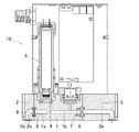
本発明に係る流路シール構造の実施形態について、以下に図1〜図7を参照して説明する。以下の説明において、弁体やアクチュエータ等の従来と同様の構成部分については、詳細な図示説明を省略する。なお、図1において圧電式アクチュエータはケース40内に隠れていて図示されていない。また、上記した従来例と同様の構成部分には同符号を付した。
An embodiment of a flow path seal structure according to the present invention will be described below with reference to FIGS. In the following description, detailed illustration and description of the same components as those of the prior art such as a valve body and an actuator will be omitted. In FIG. 1, the piezoelectric actuator is hidden in the
本体ブロック1の内部には、本体流路1a、1bが形成されている。本体ブロック1の両側の側面には、凹部12、13が形成されている。凹部12、13の奥底に本体流路1b、1aが開口するとともに、凹部12の出口側及び凹部13の入口側の内周面に雌螺子12a、13aが形成されている。なお、図1,2において雌螺子12a、13aの螺子山は省略図法により図示されている。
In the
本体流路1bに設けられた凹部12の奥底には、オリフィス(通孔)が形成された薄板であるオリフィスプレート6が当接されている。オリフィスプレート6は従来公知のものを用いることができる。
An
本体流路1aに設けられた凹部13の奥底には、複数の通孔が形成された薄板であるフィルタープレート8が当接されている。フィルタープレート8は従来公知のものを用いることができる。
A
凹部12、13の奥底に、薄板であるオリフィスプレート6、フィルタープレート8を其々嵌入可能な薄板用凹所14、15(図4、図6参照)が形成されている。薄板用凹所14、15は、オリフィスプレート6、フィルタープレート8の位置決めに役立つ。
Thin plate recesses 14 and 15 (see FIGS. 4 and 6) into which the
其々の薄板用凹所14、15は、オリフィスプレート6、フィルタープレート8が当接する環状の座面14a、15aの外周囲に環状溝部14b、15bが形成されている。環状溝部14b、15bを設けて座面14a、15aの面積を小さくすることにより、座面14a、15aから、オリフィスプレート6、フィルタープレート8にかかる圧力を増加することができる。一方、座面14a、15aは、所望のシール性能を確保するため、平坦面とすることができる。
Each of the
オリフィスプレート6は、公知の物を用いることができ、ステンレス鋼や合金等、例えばHv270〜350の硬度のステンレス鋼で製造することができ、図示例では直径が3.5mm、厚みが50μmのステンレス鋼製薄板に直径100μmのオリフィスが形成されている。
The
フィルタープレート8は、公知の物を用いることができ、ステンレス鋼、合金、セラミック等で、例えば厚みが20〜50μmの薄板の外周縁部を除く部分に多数の通孔(厚みと同程度の内径)が形成される。
The
オリフィスプレート6、フィルタープレート8に、其々、ガスケットリング16、17が当接している。ガスケットリング16、17は、例えばHv100〜130の硬度のステンレス鋼で製造することができ、図示例では焼鈍されたSUS316Lが用いられている。
Gasket rings 16 and 17 are in contact with the
本体ブロックは、例えば、硬度がHv130〜200のステンレス鋼等の金属又は合金で形成することができる。 The main body block can be formed of, for example, a metal or alloy such as stainless steel having a hardness of Hv 130 to 200.
凹部12、13の奥底に、ガスケットリング16、17の軸方向端部が嵌るガスケットリング用凹所18、19(図4、図6参照)が其々形成されている。薄板用凹所14、15は、ガスケットリング用凹所18、19の底に形成されている。図示例に於いて、座面14a、15aとガスケットリング用凹所18、19との段差d(図4、図6)は、オリフィスプレート6、フィルタープレート8の厚さと一致させてある。そのため、オリフィスプレート6、フィルタープレート8を其々の座面14a、15aに当接させた時に、オリフィスプレート6、フィルタープレート8の其々の面とガスケットリング用凹所18、19の底面とが一致するようになっている。なお、段差dは、オリフィスプレート6、フィルタープレート8の厚さ以下であればよい。また、段差dが無くても同様のシール効果を発揮する事ができる。また、薄板用凹所14、15をガスケットリング用凹所18、19の底に設けるのに代えて、ガスケットリング16,17に薄板用凹所(図示省略)を設けても良い。さらに、図示しないが、ガスケットリング16,17とガスケットリング用凹所18、19の両方に、薄板用凹所を設けても良い。
Gasket ring recesses 18 and 19 (see FIGS. 4 and 6) into which the axial ends of the gasket rings 16 and 17 fit are formed in the bottoms of the
また、円環状をしている座面14a、15aの内径と、ガスケットリング16、17の内径とは、同じなるように形成されている。 Further, the inner diameters of the annular bearing surfaces 14a and 15a and the inner diameters of the gasket rings 16 and 17 are formed to be the same.
本体流路1bのオリフィスプレート6に臨む内面1bc(図4)がテーパー状に拡開されている。これは、弁体4(図2)とオリフィスプレート6との間にある本体流路1bが、本体流路1b内のガス置換性を向上させるために流路径を小径にされているためである。
An inner surface 1bc (FIG. 4) facing the
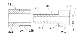
ガスケットリング16、17の其々に押え配管20、21が当接している。押え配管20、21は、本体流路1b、1aと連通可能な内部流路20a、21aを軸方向に有するとともに、拡径部20b、21bを有している。
The holding
押え配管20,21は、例えば、硬度がHv130〜200のステンレス鋼等の金属又は合金で形成することができる。
The
図示例では、押え配管20にも、ガスケットリング16の軸方向端部が嵌るガスケットリング用凹所20cが形成されている。ガスケットリング16は、両側がガスケットリング用凹所14とガスケットリング用凹所20cとに嵌り、位置決めされ得る。なお、ガスケットリング用凹所14か、ガスケットリング用凹所20cのいずれかのみを設けても良い。
In the illustrated example, the
拡径部20b、21bは、其々、ガスケットリング16、17を押圧する押圧面20d、21dを備える。そのため、拡径部20b、21bは、押え配管20,21の一端側に設けられている。押え配管20,21の寸法を小さく抑えるためには、図示例の如く拡径部20b、21bを軸方向端部に設けることが好ましいが、後述するように拡径部20b、21bが締付螺子22を受ける鍔部としての機能のみに着目すれば、押え配管20,21の軸方向端部以外(例えば軸方向中間部)に設けることもできる。
The
押え配管20,21の非拡径管状部20e、21eに、締付螺子22が外挿されている。締付螺子22は、非拡径管状部20e、21eに外挿するために軸方向に延びる挿通孔22aを有するとともに、雄螺子部22bを備える。なお、図3及び図5において雄螺子部22bは省略図法により図示されている。締付螺子22は、凹部12,13の雌螺子12a,13aに螺入されて、拡径部20b、21bに当接し、押え配管20,21をガスケット16,17に押し付ける。締付螺子22の頭部22cは、一般的な六角ボルトと同様の六角形とすることができ、好ましくは、頭部22cの最小外径(六角形の対向する2辺間の距離h(図1(b)))を、雄螺子部22bの外径と同じにして、できるだけ頭部22cの寸法を小さくなされる。非拡径管状部20e,21eは、締付螺子22より長尺であり、締付螺子22から突き出している。非拡径管状部20e,21eは、締付螺子22から突き出している部分で、図示しない他の配管等と連結される。
A tightening
締付螺子22を螺入する際に押え配管20,21が共回りしないように、共回り防止機構23が設けられている。押え配管20,21が共回りすると、ガスケットリング16,17を共回りさせ、共回りするガスケットリング16,17によって、高精度に加工されているオリフィスプレート6やフィルタープレート8を損傷させる恐れがあるからである。
A
共回り防止機構23は、拡径部20b、21bに形成された被係合部23aと、本体ブロック1に設けられて被係合部23aに係合する係合部23bと、を備えることができる。
The
被係合部23aを、拡径部20b、21bの外周面に平坦面を切欠き形成することにより形成された回り止め面(図7も参照)とし、係合部23bを本体ブロック1の挿通孔1cに圧入されたノックピンとして、ノックピンを平坦面と平行に圧入し、平行ピンの側面を回り止め面に当接させることにより、係合させることができる。ノックピンは本体ブロック1に形成された挿入孔1c(図1)に圧入して固定するため、施行性及び小型化に適している。係合部23bは、他のノックピン、例えば、スプリングピン、ねじ込み用ストップピン等も用いられ得る。
The engaged
共回り防止機構は、締付螺子22による押え配管20,21の共回りを防ぐことができる機構であれば、機械部品の回り止めに用いられるその他の公知の回り止め機構を用いることもでき、例えば、拡径部の外形を六角形等の多角形にして、凹部12,13の内面で拡径部が嵌る部分の内周面形状を拡径部が嵌合する多角形としても良いし、キーとキー溝とが係合する構成としても良い。
As long as the co-rotation preventing mechanism is a mechanism that can prevent co-rotation of the holding
或いは、共回り防止機構として、拡径部20b、21bと締付螺子22との間に、スラストベアリングや動摩擦係数が拡径部20b、21bより小さいスラストリング等の摺動部材(図示省略)を介在させることにより、締付螺子22を締付ける時に、ガスケットリング16、17やオリフィスプレート6、フィルタープレート8が締付螺子22と共回りすることを防止することができる。
Alternatively, a sliding member (not shown) such as a thrust bearing or a thrust ring whose dynamic friction coefficient is smaller than that of the
上記構成の流路シール構造を構成する構成部品を組み立てるには、例えば、本体ブロック1を凹部12のガス出口側(図2の上側)が上側(奥底側が下側)になるようにして、凹部12にオリフィスプレート6を挿入し、凹部12の奥底に設けた座面14aにオリフィスプレート6を当接させる。その際、薄板用凹所14にオリフィスプレート6を嵌めることにより位置決めすることができる。次に、ガスケットリング16を本体ブロック1の凹部12に挿入し、凹部12の奥底のガスケット凹所14にガスケットリング16を収容し、ガスケットリング16をオリフィスプレート6に当接させる。次いで凹部12に押え配管20を挿入し、ガスケットリング16に当接させる。押え配管20に共回り防止用の係合部23bであるノックピンを非係合部23aである回り止め面に係合させる。係合部23bであるノックピンは、押え配管20を凹部12に挿入する前に予めセットしておいても良い。最後に締付螺子22を、凹部12に挿入して凹部12の雌螺子12aに螺入し、所定の締付トルクで締め付けて、ガスケットリング16を押圧し、オリフィスプレート6の両面を、座面14aとガスケットリング16とでシールする。図示例でガスケットリング16は、オリフィスプレート6に当接すると同時に、ガスケットリング用凹所18の底面18aにも当接し、ガスケットリング用凹所18の底面18a及びエッジ部分18bでもシールがなされる。フィルタープレート8の場合もオリフィスプレート6と同様の方法で組み込まれる。雌螺子12a,13aは、押え配管20,21がガスケットリング16,17を押え過ぎないように、所要深さまで螺刻されている。
In order to assemble the components constituting the flow path seal structure having the above-described configuration, for example, the
上記構成を有する流路シール構造によれば、薄板であるオリフィスプレート6、フィルタープレート8を、本体ブロック1の凹部12、13の奥底とガスケットリング16,17とに圧接させ、オリフィスプレート6、フィルタープレート8の両面をシール面として用いることにより、溶接工程やカシメ工程を省くことができる。
According to the flow path seal structure having the above configuration, the
押え配管20,21は、配管とガスケットリング16,17の押えとが一体になっているので、部品点数を減らし、小型化にも寄与する。また、本体ブロック1に凹部12,13を形成して凹部12,13に押え配管20,21を挿入し締結螺子22を螺入していることも、小型化に寄与している。さらに、押え配管20,21を押圧するのに、押え配管20,21に外挿する締付螺子22を用い、本体ブロック1の凹部12,13に形成した雌螺子12a、13aに螺入するので、斯かる構成によっても小型化がなされ、特に、本体ブロック1の厚み寸法W(図1参照)を小さくして薄型化を図ることが可能となり、図示例では厚み寸法Wを10mmにしている。
Since the
本発明は上記実施形態に限定解釈されるものではなく、本発明の要旨を逸脱しない範囲において種々の変更が可能である。 The present invention is not construed as being limited to the above-described embodiments, and various modifications can be made without departing from the scope of the present invention.
1 本体ブロック
1a、1b 本体流路
12,13 凹部
12a、13a 雌螺子
6、8 薄板
14、15 薄板用凹所
14a、15a 座面
14b、15b 環状溝部
16、17 ガスケットリング
18、19 ガスケットリング用凹所
20a、21a 内部流路
20b、21b 拡径部
20、21 押え配管
22a 挿通孔
22 締付螺子
23 共回り防止機構
23a 被係合部
23b 係合部
20d、21d 押圧面
DESCRIPTION OF
Claims (11)
前記本体ブロックに形成された凹部であって、該凹部の奥底に前記本体流路が開口するとともに、該凹部の内周面に雌螺子が形成された前記凹部と、
前記凹部の奥底に当接されて通孔が形成された薄板と、
前記薄板に当接するガスケットリングと、
前記本体流路と連通可能な内部流路と、拡径部とを有し、前記ガスケットリングに当接する押え配管と、
軸方向に挿通孔を有し、該挿通孔を介して前記押え配管に外挿されるとともに前記雌螺子に螺入されて、前記拡径部に当接して前記押え配管を押圧する締付螺子と、
を備えることを特徴とする流路シール構造。 A body block in which a body channel is formed;
A concave portion formed in the main body block, wherein the main body flow path opens at the bottom of the concave portion, and the concave portion in which a female screw is formed on an inner peripheral surface of the concave portion,
A thin plate with a through hole formed in contact with the bottom of the recess;
A gasket ring in contact with the thin plate;
An internal flow path capable of communicating with the main body flow path, a diameter increasing portion, and a presser pipe that contacts the gasket ring;
A fastening screw that has an insertion hole in the axial direction, is externally inserted into the holding pipe through the insertion hole, is screwed into the female screw, and abuts against the enlarged diameter portion to press the holding pipe; ,
A flow path seal structure comprising:
The channel seal structure according to claim 1, wherein the thin plate is an orifice plate, and an inner surface of the main body channel facing the orifice plate is expanded in a tapered shape.
Priority Applications (6)
| Application Number | Priority Date | Filing Date | Title |
|---|---|---|---|
| JP2013269780A JP5982355B2 (en) | 2013-12-26 | 2013-12-26 | Channel seal structure |
| KR1020167003235A KR101800682B1 (en) | 2013-12-26 | 2014-12-22 | Flow passage sealing structure |
| US15/107,044 US10309561B2 (en) | 2013-12-26 | 2014-12-22 | Flow passage sealing structure |
| PCT/JP2014/006386 WO2015098087A1 (en) | 2013-12-26 | 2014-12-22 | Flow passage sealing structure |
| CN201480054854.6A CN105814410B (en) | 2013-12-26 | 2014-12-22 | Flow path seal construction |
| TW103145512A TWI545304B (en) | 2013-12-26 | 2014-12-25 | Flow path sealing structure |
Applications Claiming Priority (1)
| Application Number | Priority Date | Filing Date | Title |
|---|---|---|---|
| JP2013269780A JP5982355B2 (en) | 2013-12-26 | 2013-12-26 | Channel seal structure |
Publications (3)
| Publication Number | Publication Date |
|---|---|
| JP2015125061A JP2015125061A (en) | 2015-07-06 |
| JP2015125061A5 JP2015125061A5 (en) | 2015-11-26 |
| JP5982355B2 true JP5982355B2 (en) | 2016-08-31 |
Family
ID=53477984
Family Applications (1)
| Application Number | Title | Priority Date | Filing Date |
|---|---|---|---|
| JP2013269780A Active JP5982355B2 (en) | 2013-12-26 | 2013-12-26 | Channel seal structure |
Country Status (6)
| Country | Link |
|---|---|
| US (1) | US10309561B2 (en) |
| JP (1) | JP5982355B2 (en) |
| KR (1) | KR101800682B1 (en) |
| CN (1) | CN105814410B (en) |
| TW (1) | TWI545304B (en) |
| WO (1) | WO2015098087A1 (en) |
Families Citing this family (4)
| Publication number | Priority date | Publication date | Assignee | Title |
|---|---|---|---|---|
| CN108351062B (en) * | 2015-10-30 | 2019-10-11 | 株式会社富士金 | The connection method of distribution tube connection structure, piping fastening means and piping |
| KR102304548B1 (en) * | 2017-11-24 | 2021-09-27 | 가부시키가이샤 후지킨 | Valve device and control method using the same, fluid control device and semiconductor manufacturing device |
| DE102018000084A1 (en) * | 2018-01-09 | 2019-07-11 | Drägerwerk AG & Co. KGaA | Flow tube for a flow sensor and methods for producing a flow tube |
| CN113366251A (en) * | 2019-01-31 | 2021-09-07 | 株式会社富士金 | Flow path module, valve device using the flow path module, fluid control device, semiconductor manufacturing device, and semiconductor manufacturing method |
Family Cites Families (30)
| Publication number | Priority date | Publication date | Assignee | Title |
|---|---|---|---|---|
| US595338A (en) * | 1897-12-14 | Insulated joint for gas-fixtures | ||
| DE843777C (en) * | 1944-09-20 | 1952-07-14 | Bergedorfer Eisenwerk Ag | Pressure level control for breast pumps |
| US2626820A (en) * | 1947-05-12 | 1953-01-27 | Eddie M Dons | Pipe coupling |
| US2661768A (en) * | 1949-10-29 | 1953-12-08 | Standard Oil Dev Co | Indicating orifice plate for threaded orifice union |
| FR1025206A (en) * | 1949-10-29 | 1953-04-13 | Standard Oil Dev Co | Indicator orifice plate for threaded pipe fittings |
| US2774616A (en) * | 1953-05-07 | 1956-12-18 | Roy F Dodd | Quick release coupling having detachable screw thimble-gland |
| US3749122A (en) * | 1971-04-27 | 1973-07-31 | H Gold | System for installing fluid elements in conduit circuits |
| US3792609A (en) * | 1971-05-10 | 1974-02-19 | Tylan Corp | Flow splitter |
| JPS51134465U (en) * | 1975-04-21 | 1976-10-29 | ||
| US4324112A (en) * | 1979-05-10 | 1982-04-13 | Nippondenso Co., Ltd. | Refrigeration system |
| US4356997A (en) * | 1980-09-29 | 1982-11-02 | Quality Valve And Machine Works, Inc. | Flow control mechanism for high pressure wells |
| FR2498726B1 (en) * | 1981-01-23 | 1986-01-10 | Commissariat Energie Atomique | ELASTIC TIGHTENING CONNECTION DEVICE |
| US4665960A (en) * | 1985-03-04 | 1987-05-19 | Cajon Company | Coded coupling |
| US5054822A (en) * | 1985-09-16 | 1991-10-08 | Go, Inc. | Anti-twist union |
| GB2197409B (en) * | 1986-10-31 | 1990-08-22 | Kitz Corp | Pipe joint |
| JP3686748B2 (en) * | 1997-08-15 | 2005-08-24 | 忠弘 大見 | Orifice for pressure flow control device and method for manufacturing the same |
| JP4042190B2 (en) * | 1997-12-11 | 2008-02-06 | Smc株式会社 | Flow rate detector with flow control valve |
| JP4370369B2 (en) * | 1998-12-01 | 2009-11-25 | 株式会社フジキン | Gasket filter |
| CN2438102Y (en) * | 2000-06-16 | 2001-07-04 | 新疆石油管理局采油工艺研究院 | Orifice throttle metering device |
| JP2003074798A (en) * | 2001-08-30 | 2003-03-12 | Koda:Kk | High pressure gas cylinder valve |
| CN2578639Y (en) * | 2002-11-11 | 2003-10-08 | 建湖县鸿达阀门管件有限公司 | Regulatable orifice throttle valves |
| US6810683B2 (en) * | 2003-02-11 | 2004-11-02 | General Motors Corporation | Thermostatic expansion valve exit flow silencer device |
| JP4298476B2 (en) * | 2003-11-14 | 2009-07-22 | 株式会社フジキン | Fluid control device |
| US20060070437A1 (en) * | 2004-09-30 | 2006-04-06 | Rosemount Inc. | Gasket arrangement for sanitary process flow meter |
| CN2821354Y (en) * | 2005-06-15 | 2006-09-27 | 乔狮雄 | Simple pipeline connecting structure |
| JP4690827B2 (en) | 2005-08-26 | 2011-06-01 | 株式会社フジキン | Gasket type orifice and pressure type flow control device using the same |
| JP5301983B2 (en) * | 2008-12-26 | 2013-09-25 | 株式会社フジキン | Gasket type orifice and pressure type flow control device using the same |
| JP5102384B2 (en) * | 2011-05-12 | 2012-12-19 | 富士工器株式会社 | Diaphragm pressure regulator |
| CN102829586B (en) * | 2011-06-15 | 2015-05-27 | 浙江三花股份有限公司 | Electronic expansion valve and manufacturing method therefor |
| CN102928027A (en) * | 2012-10-27 | 2013-02-13 | 江阴市神州测控设备有限公司 | Adjustable flow meter |
-
2013
- 2013-12-26 JP JP2013269780A patent/JP5982355B2/en active Active
-
2014
- 2014-12-22 WO PCT/JP2014/006386 patent/WO2015098087A1/en active Application Filing
- 2014-12-22 KR KR1020167003235A patent/KR101800682B1/en active IP Right Grant
- 2014-12-22 US US15/107,044 patent/US10309561B2/en not_active Expired - Fee Related
- 2014-12-22 CN CN201480054854.6A patent/CN105814410B/en not_active Expired - Fee Related
- 2014-12-25 TW TW103145512A patent/TWI545304B/en not_active IP Right Cessation
Also Published As
| Publication number | Publication date |
|---|---|
| CN105814410A (en) | 2016-07-27 |
| WO2015098087A1 (en) | 2015-07-02 |
| US20170037987A1 (en) | 2017-02-09 |
| KR101800682B1 (en) | 2017-11-23 |
| JP2015125061A (en) | 2015-07-06 |
| TWI545304B (en) | 2016-08-11 |
| TW201537146A (en) | 2015-10-01 |
| CN105814410B (en) | 2019-05-14 |
| US10309561B2 (en) | 2019-06-04 |
| KR20160028475A (en) | 2016-03-11 |
Similar Documents
| Publication | Publication Date | Title |
|---|---|---|
| JP5982355B2 (en) | Channel seal structure | |
| JP6531162B2 (en) | Ultra-sealed gaskets for joining high purity fluid passages | |
| CA2490664A1 (en) | Flowline clamp connector | |
| JP5586023B2 (en) | Butterfly valve and seat ring | |
| US20090174149A1 (en) | Mechanical seal device | |
| WO2018021294A1 (en) | Pipe joint | |
| JP5213636B2 (en) | Seal device for joint and fluid joint having the same | |
| JP5696341B2 (en) | Triple eccentric butterfly valve | |
| WO2014142321A1 (en) | Fluid-throttling member | |
| JP2011044293A (en) | Check valve for fuel injection | |
| US7537244B2 (en) | Fluid fitting assembly | |
| JP6943430B2 (en) | Manufacturing method of fluid coupling and valve holder | |
| JP6710254B2 (en) | Trunnion type ball valve | |
| JP5399476B2 (en) | Threaded connection piece and sensor | |
| JP5780426B2 (en) | Joint structure and connection method | |
| JP2010265998A (en) | Fuel filling check valve | |
| US10323753B2 (en) | Gasket seal seat ring | |
| JP4933333B2 (en) | Eccentric butterfly valve | |
| JP6854276B2 (en) | Press-fit check valve for hydraulic tensioner reservoir with weighed backflow | |
| JP4758386B2 (en) | Sealing device | |
| JP2014185674A (en) | Connection mechanism of thin stainless steel pipe and joint | |
| JP2006220197A (en) | Ball valve | |
| JP2016105026A (en) | Assembling method of ball screw device | |
| JP2016217504A (en) | Check valve element and check valve using the same | |
| JP2007303518A (en) | Flange part seal structure and packing with o-ring |
Legal Events
| Date | Code | Title | Description |
|---|---|---|---|
| A521 | Request for written amendment filed |
Free format text: JAPANESE INTERMEDIATE CODE: A821 Effective date: 20151005 Free format text: JAPANESE INTERMEDIATE CODE: A523 Effective date: 20151005 |
|
| A621 | Written request for application examination |
Free format text: JAPANESE INTERMEDIATE CODE: A621 Effective date: 20151005 |
|
| TRDD | Decision of grant or rejection written | ||
| A01 | Written decision to grant a patent or to grant a registration (utility model) |
Free format text: JAPANESE INTERMEDIATE CODE: A01 Effective date: 20160704 |
|
| A61 | First payment of annual fees (during grant procedure) |
Free format text: JAPANESE INTERMEDIATE CODE: A61 Effective date: 20160801 |
|
| R150 | Certificate of patent or registration of utility model |
Ref document number: 5982355 Country of ref document: JP Free format text: JAPANESE INTERMEDIATE CODE: R150 |
|
| R250 | Receipt of annual fees |
Free format text: JAPANESE INTERMEDIATE CODE: R250 |
|
| R250 | Receipt of annual fees |
Free format text: JAPANESE INTERMEDIATE CODE: R250 |
|
| R250 | Receipt of annual fees |
Free format text: JAPANESE INTERMEDIATE CODE: R250 |
|
| R250 | Receipt of annual fees |
Free format text: JAPANESE INTERMEDIATE CODE: R250 |
|
| R250 | Receipt of annual fees |
Free format text: JAPANESE INTERMEDIATE CODE: R250 |