WO2014141872A1 - 海水淡水化システムおよびエネルギー回収装置 - Google Patents
海水淡水化システムおよびエネルギー回収装置 Download PDFInfo
- Publication number
- WO2014141872A1 WO2014141872A1 PCT/JP2014/054493 JP2014054493W WO2014141872A1 WO 2014141872 A1 WO2014141872 A1 WO 2014141872A1 JP 2014054493 W JP2014054493 W JP 2014054493W WO 2014141872 A1 WO2014141872 A1 WO 2014141872A1
- Authority
- WO
- WIPO (PCT)
- Prior art keywords
- seawater
- chamber
- energy recovery
- concentrated seawater
- concentrated
- Prior art date
- Legal status (The legal status is an assumption and is not a legal conclusion. Google has not performed a legal analysis and makes no representation as to the accuracy of the status listed.)
- Ceased
Links
Images






Classifications
-
- C—CHEMISTRY; METALLURGY
- C02—TREATMENT OF WATER, WASTE WATER, SEWAGE, OR SLUDGE
- C02F—TREATMENT OF WATER, WASTE WATER, SEWAGE, OR SLUDGE
- C02F1/00—Treatment of water, waste water, or sewage
- C02F1/44—Treatment of water, waste water, or sewage by dialysis, osmosis or reverse osmosis
- C02F1/441—Treatment of water, waste water, or sewage by dialysis, osmosis or reverse osmosis by reverse osmosis
-
- B—PERFORMING OPERATIONS; TRANSPORTING
- B01—PHYSICAL OR CHEMICAL PROCESSES OR APPARATUS IN GENERAL
- B01D—SEPARATION
- B01D61/00—Processes of separation using semi-permeable membranes, e.g. dialysis, osmosis or ultrafiltration; Apparatus, accessories or auxiliary operations specially adapted therefor
- B01D61/02—Reverse osmosis; Hyperfiltration ; Nanofiltration
- B01D61/025—Reverse osmosis; Hyperfiltration
-
- B—PERFORMING OPERATIONS; TRANSPORTING
- B01—PHYSICAL OR CHEMICAL PROCESSES OR APPARATUS IN GENERAL
- B01D—SEPARATION
- B01D61/00—Processes of separation using semi-permeable membranes, e.g. dialysis, osmosis or ultrafiltration; Apparatus, accessories or auxiliary operations specially adapted therefor
- B01D61/02—Reverse osmosis; Hyperfiltration ; Nanofiltration
- B01D61/06—Energy recovery
-
- B—PERFORMING OPERATIONS; TRANSPORTING
- B01—PHYSICAL OR CHEMICAL PROCESSES OR APPARATUS IN GENERAL
- B01D—SEPARATION
- B01D61/00—Processes of separation using semi-permeable membranes, e.g. dialysis, osmosis or ultrafiltration; Apparatus, accessories or auxiliary operations specially adapted therefor
- B01D61/02—Reverse osmosis; Hyperfiltration ; Nanofiltration
- B01D61/12—Controlling or regulating
-
- C—CHEMISTRY; METALLURGY
- C02—TREATMENT OF WATER, WASTE WATER, SEWAGE, OR SLUDGE
- C02F—TREATMENT OF WATER, WASTE WATER, SEWAGE, OR SLUDGE
- C02F1/00—Treatment of water, waste water, or sewage
- C02F1/008—Control or steering systems not provided for elsewhere in subclass C02F
-
- B—PERFORMING OPERATIONS; TRANSPORTING
- B01—PHYSICAL OR CHEMICAL PROCESSES OR APPARATUS IN GENERAL
- B01D—SEPARATION
- B01D2313/00—Details relating to membrane modules or apparatus
- B01D2313/18—Specific valves
-
- C—CHEMISTRY; METALLURGY
- C02—TREATMENT OF WATER, WASTE WATER, SEWAGE, OR SLUDGE
- C02F—TREATMENT OF WATER, WASTE WATER, SEWAGE, OR SLUDGE
- C02F2103/00—Nature of the water, waste water, sewage or sludge to be treated
- C02F2103/08—Seawater, e.g. for desalination
-
- C—CHEMISTRY; METALLURGY
- C02—TREATMENT OF WATER, WASTE WATER, SEWAGE, OR SLUDGE
- C02F—TREATMENT OF WATER, WASTE WATER, SEWAGE, OR SLUDGE
- C02F2209/00—Controlling or monitoring parameters in water treatment
- C02F2209/005—Processes using a programmable logic controller [PLC]
-
- C—CHEMISTRY; METALLURGY
- C02—TREATMENT OF WATER, WASTE WATER, SEWAGE, OR SLUDGE
- C02F—TREATMENT OF WATER, WASTE WATER, SEWAGE, OR SLUDGE
- C02F2209/00—Controlling or monitoring parameters in water treatment
- C02F2209/40—Liquid flow rate
-
- C—CHEMISTRY; METALLURGY
- C02—TREATMENT OF WATER, WASTE WATER, SEWAGE, OR SLUDGE
- C02F—TREATMENT OF WATER, WASTE WATER, SEWAGE, OR SLUDGE
- C02F2303/00—Specific treatment goals
- C02F2303/10—Energy recovery
-
- Y—GENERAL TAGGING OF NEW TECHNOLOGICAL DEVELOPMENTS; GENERAL TAGGING OF CROSS-SECTIONAL TECHNOLOGIES SPANNING OVER SEVERAL SECTIONS OF THE IPC; TECHNICAL SUBJECTS COVERED BY FORMER USPC CROSS-REFERENCE ART COLLECTIONS [XRACs] AND DIGESTS
- Y02—TECHNOLOGIES OR APPLICATIONS FOR MITIGATION OR ADAPTATION AGAINST CLIMATE CHANGE
- Y02A—TECHNOLOGIES FOR ADAPTATION TO CLIMATE CHANGE
- Y02A20/00—Water conservation; Efficient water supply; Efficient water use
- Y02A20/124—Water desalination
- Y02A20/131—Reverse-osmosis
-
- Y—GENERAL TAGGING OF NEW TECHNOLOGICAL DEVELOPMENTS; GENERAL TAGGING OF CROSS-SECTIONAL TECHNOLOGIES SPANNING OVER SEVERAL SECTIONS OF THE IPC; TECHNICAL SUBJECTS COVERED BY FORMER USPC CROSS-REFERENCE ART COLLECTIONS [XRACs] AND DIGESTS
- Y02—TECHNOLOGIES OR APPLICATIONS FOR MITIGATION OR ADAPTATION AGAINST CLIMATE CHANGE
- Y02W—CLIMATE CHANGE MITIGATION TECHNOLOGIES RELATED TO WASTEWATER TREATMENT OR WASTE MANAGEMENT
- Y02W10/00—Technologies for wastewater treatment
- Y02W10/30—Wastewater or sewage treatment systems using renewable energies
Definitions
- the present invention relates to a seawater desalination system that desalinates seawater by removing salinity from seawater, and an energy recovery apparatus suitably used for the seawater desalination system.
- seawater desalination system in which seawater is passed through a reverse osmosis membrane separation device for desalting as a system for desalinizing seawater.
- the intake seawater is adjusted to a condition of constant water quality by the pretreatment device, then pressurized by the high pressure pump and pressure-fed to the reverse osmosis membrane separation device, and the reverse osmosis membrane separation device A portion of the high-pressure seawater inside is overcome the reverse osmosis pressure, passes through the reverse osmosis membrane, and is taken out as desalinated fresh water.
- the other seawater is discharged as concentrated seawater (brine) from the reverse osmosis membrane separation device in a state where the salinity is high and concentrated.
- the largest operating cost in the seawater desalination system is the power cost, and it depends largely on the energy for raising the seawater after pretreatment to the pressure that can overcome the osmotic pressure, that is, the reverse osmotic pressure, that is, the pressurized energy by the high pressure pump Do.
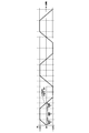
- FIG. 13 is a schematic view showing a configuration example of a conventional seawater desalination system.
- the seawater taken in by the intake pump (not shown) is removed by the pretreatment device 1 to remove suspended solids etc. and adjusted to a predetermined water quality condition, and then passes through the water pump 2 and the high pressure pump line Branch to 3 and energy recovery unit seawater supply line 4.
- the seawater flowing into the high pressure pump 5 is pressurized by the high pressure pump 5, joined with the seawater pressurized by the energy recovery device 10 and the booster pump 7, and then pressure-fed to the reverse osmosis membrane separation device 8.
- a portion of the seawater introduced into the reverse osmosis membrane separator 8 overcomes the reverse osmosis pressure and passes through the reverse osmosis membrane (RO membrane) 8a in the reverse osmosis membrane separator 8 as desalted water from which salt has been removed It is taken out via a demineralized water line.
- the other seawater has a high salinity and becomes concentrated concentrated seawater, which is introduced from the reverse osmosis membrane separation device 8 to the energy recovery device 10 through the concentrated seawater line 9.
- the seawater pressurized in the energy recovery chambers 11 and 12 is supplied from the check valve module 15 to the booster pump 7 via the booster pump seawater supply line 6.
- the booster pump 7 boosts the pressure loss of the reverse osmosis membrane separation device 8 and the piping, the pressure loss of the control valve 14, the pressure loss generated in the energy recovery chambers 11, 12 and the check valve module 15, and after boosting
- the seawater is discharged from the high pressure pump 5 to merge with the seawater, and is pumped to the reverse osmosis membrane separation device 8.
- the piston in the energy recovery chamber slides on the inner wall of the cylinder, and the sliding member of the piston wears, so regular replacement is necessary, and a long chamber is also required.
- the machining cost is very expensive because the inner diameter of the cylinder needs to be precisely machined according to the outer diameter of the piston. Therefore, in the patent document 1, the applicant of the present invention uses the cylindrical long chamber as a pressure exchange chamber, provides a plurality of divided flow paths in the chamber, and concentrates the high pressure discharged from the reverse osmosis membrane (RO membrane)
- RO membrane reverse osmosis membrane
- a magnet is incorporated in the piston, and a magnet switch for detecting magnetism is provided outside the chamber to detect the position of the piston. Since the piston moves while separating concentrated seawater and seawater, this magnet switch is provided in the vicinity of both ends of the chamber and the moving direction of the piston is switched by a control valve or the like to reciprocate in the chamber. The control was to switch the In addition, detecting the position of a piston using a proximity sensor, a laser, a photo sensor, etc. is also performed. On the other hand, the energy recovery chamber having no piston can not control the amount of water supply and discharge in the same manner because there is no piston. For this reason, it is necessary to perform control which switches water supply and drainage of seawater and concentrated seawater with another means and method.
- the present invention has been made in view of the above-mentioned circumstances, and in any of the energy recovery chamber without the piston and the energy recovery chamber with the piston, switching between supply and drainage of concentrated seawater and seawater to the energy recovery chamber is required.
- An object of the present invention is to provide an energy recovery apparatus that can be performed at an accurate timing.
- the energy recovery apparatus of the present invention flows seawater pumped by a pump to a reverse osmosis membrane separation apparatus, separates it into freshwater and concentrated seawater, and produces freshwater from seawater.
- a reverse osmosis membrane separation apparatus In an energy recovery apparatus provided in a system and utilizing pressure energy of concentrated seawater discharged from the reverse osmosis membrane separation device as energy for pressurizing a part of the seawater, the concentrated seawater and seawater are supplied and drained, and the pressure of concentrated seawater is supplied.
- a plurality of chambers for pressurizing seawater by energy a first flow meter used to integrate the flow of seawater or concentrated seawater flowing into the chamber, and integrating the flow of seawater or concentrated seawater discharged from the chamber Installed in each of the plurality of chambers, the flow of concentrated seawater into each chamber and each The integrated flow rate of the chamber is determined based on the flow rate of the first flow meter and / or the second flow rate meter, and the plurality of the plurality of flow rates are determined based on the integrated flow rate.
- a control device for controlling each switching valve of the chamber wherein the control device controls each switching valve by inputting a single input signal to each switching valve of the plurality of chambers.
- concentrated seawater discharged from the reverse osmosis membrane separation device is supplied / drained to a plurality of chambers via a switching valve and seawater is supplied / drained to a plurality of chambers, whereby seawater is concentrated by concentrated seawater in each chamber.
- the pressure can be boosted and discharged (discharged).
- the integrated flow rate is determined by measuring the flow rate of seawater or concentrated seawater flowing into the chamber with a first flow meter, and the flow rate of seawater or concentrated seawater discharged from the chamber is measured by a second flow meter to determine an integrated flow rate
- the opening degree of the switching valve By controlling the opening degree of the switching valve by grasping the amount of inflow to the chamber of seawater or concentrated seawater and / or the amount of discharge from the chamber based on the integrated flow rate determined, supply of concentrated seawater and seawater to the chamber Switching can be performed at the correct timing. Furthermore, since the opening degree can be adjusted by one input signal for each switching valve installed in a plurality of chambers, control of a large number of switching valves can be performed easily and reliably.
- the opening degree and switching time of each switching valve can be controlled by the single input signal. According to the present invention, since the opening degree and the switching time of the switching valve can be adjusted by one input signal, it is possible to control a large number of switching valves more accurately.
- a trapezoidal wave is used as the single input signal. According to the present invention, by setting the time during which the input signal value takes a constant value, it is possible to adjust the time for keeping the opening degree of each switching valve constant.
- the opening degree of each of the switching valves is set to change with respect to the input signal based on a preset set value. According to the present invention, since the switching valve is controlled based on the setting value representing the inherent relationship between the input signal value and the opening degree of each switching valve, the opening degree of each switching valve is changed by changing the setting value. It is possible to control while correcting.
- the control device switches the switching valve of the chamber when the integrated flow rate of the chamber by the first flow meter or the second flow meter reaches a predetermined value.
- the switching valve is switched when the integrated flow rate reaches a predetermined value after the integration by the first flow meter or the second flow meter is started, so the amount of concentrated seawater flowing into the chamber is predetermined
- the inflow of concentrated seawater can be stopped when the value is reached. Therefore, concentrated seawater does not flow into the booster pump from the energy recovery device.
- the inflow of concentrated seawater into the chamber can be determined from the integrated flow rate measured by the first flow meter.
- the discharge amount (discharge amount) of the seawater from the chamber can be obtained from the integrated flow rate of the seawater measured by the second flow meter.
- the inflow of concentrated seawater into the chamber can be determined.
- switching of the switching valve is performed at a value calculated from a predetermined ratio of the actual volume of the chamber.
- the inflow of concentrated seawater can be stopped when the inflow of the concentrated seawater into the chamber reaches a predetermined percentage (for example, 80 to 90%) of the actual volume of the chamber. Does not flow from the energy recovery device into the booster pump.
- the inflow of concentrated seawater into the chamber may be determined from the integrated flow rate of the first flow meter, or may be determined from the integrated flow rate of the second flow meter.
- the control device compares the integrated value of the inflow of concentrated seawater into the chamber with the integrated value of the discharge of concentrated seawater from the chamber, and discharges the chamber from the chamber. Control the flow rate of concentrated seawater.
- the integrated value of the inflow of concentrated seawater into the chamber and the integrated value of the discharge of concentrated seawater from the chamber are compared, and the flow rate of concentrated seawater discharged from the chamber is controlled. Since the discharge amount of concentrated seawater discharged from the chamber is equal to the inflow amount of seawater flowing into the chamber, the inflow amount of seawater into the chamber can be determined by determining the discharge amount of concentrated seawater from the chamber.
- the integrated value of the inflow of seawater into the chamber and the integrated value of seawater discharged from the chamber are compared, the integrated value of the inflow of concentrated seawater into the chamber and the integrated value of seawater discharged from the chamber Comparison-It goes without saying that the balance can be taken by comparing the integrated value of the inflow of seawater into the chamber and the integrated value of the discharge of concentrated seawater from the chamber as well, the point is that the fluid flowing into the chamber By comparing the integrated value of fluid discharged from the chamber with the chamber, the flow of concentrated seawater into the booster pump is avoided.
- the control of the switching valve can freely adjust the inflow of seawater into the chamber and the inflow of concentrated seawater into the chamber.
- the controller switches the switching so that the integrated value of the inflow of seawater into the chamber is equal to or greater than the integrated value of the inflow of concentrated seawater into the chamber. It is characterized by controlling a valve. According to the present invention, since the switching valve is controlled such that the integrated value of the inflow of seawater into the chamber is equal to or greater than the integrated value of the inflow of concentrated seawater into the chamber, the concentrated seawater has an energy recovery device Does not flow into the booster pump.
- the control device controls each of the switching valves so as to include a step of simultaneously discharging pressurized seawater from a plurality of chambers.
- the step of suctioning seawater and the step of pressurizing and discharging the sucked seawater with concentrated seawater are repeated.
- the other steps are repeated.
- the switching valve is controlled such that the pressurized seawater is simultaneously discharged from the plurality of chambers, that is, the pulsation of the pressurized seawater is suppressed by overlapping the seawater discharging steps of the plurality of chambers. it can.
- the energy recovery apparatus is provided in a seawater desalination system for passing seawater pressurized by a pump to a reverse osmosis membrane separation device to separate it into freshwater and concentrated seawater and producing freshwater from seawater, the reverse osmosis membrane
- an energy recovery apparatus that uses pressure energy of concentrated seawater discharged from a separation device for energy that pressurizes a part of the seawater, a plurality of chambers that supply and drain the concentrated seawater and seawater and pressurize the seawater by pressure energy of the concentrated seawater
- at least one switching valve installed in each of the plurality of chambers to switch the inflow of concentrated seawater into each chamber and the discharge of concentrated seawater from each chamber, and a single switching valve of each of the plurality of chambers.
- a controller for controlling each of the switching valves by inputting an input signal.
- concentrated seawater discharged from the reverse osmosis membrane separation device is supplied / drained to a plurality of chambers via a switching valve and seawater is supplied / drained to a plurality of chambers, whereby seawater is concentrated by concentrated seawater in each chamber.
- the pressure can be boosted and discharged (discharged). Furthermore, since the opening degree can be adjusted by one input signal for each switching valve installed in a plurality of chambers, control of a large number of switching valves can be performed easily and reliably.
- the seawater desalination system according to the present invention is a seawater desalination system in which seawater pressurized by a pump is fed to a reverse osmosis membrane separation device to separate it into freshwater and concentrated seawater and produce freshwater from seawater,
- the energy recovery device according to any one of claims 1 to 10, wherein pressure energy of concentrated seawater discharged from the device is used to pressurize a part of the seawater.
- the following effects can be obtained. 1) It is possible to switch between concentrated seawater and seawater supply / drainage to multiple chambers at an accurate timing, so there is no need to send seawater with high salinity concentration to the reverse osmosis membrane separation device, so While being able to fully demonstrate the performance of a reverse osmosis membrane separation apparatus without making it fall, the exchange period of reverse osmosis membrane itself can be lengthened. 2) Since a plurality of switching valves can be interlocked and operated by inputting one input signal, it is possible to save time and effort for determining the opening and closing order of the plurality of switching valves.
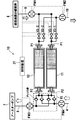
- FIG. 1 is a schematic diagram which shows the structural example of the seawater desalination system of this invention.
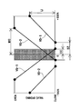
- FIG. 2 is a schematic view showing a configuration example of the energy recovery apparatus of the present invention.
- FIG. 3 is a graph showing the relationship between the opening degree of the switching valve (vertical axis) and the input signal (horizontal axis).
- FIG. 4 is a diagram showing a trapezoidal wave signal indicating the relationship between the input signal value IV and time.
- FIG. 5 is a graph showing the relationship between the opening degree of the switching valve (vertical axis) and the input signal (horizontal axis).
- FIG. 6 is a diagram showing the state of the energy recovery apparatus according to the change of the input signal value using the input signal values 0, S, U, and ⁇ 100% shown in FIG.
- FIG. 7 is a diagram showing the opening / closing operation of the switching valve when the input signal value IV is changed in the form of a trapezoidal wave in a range of ⁇ 100%.
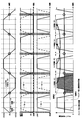
- FIG. 8 is a graph showing the relationship between the input signal to the switching valve, the switching operation of each switching valve, the flow rate of intake seawater to the energy recovery chamber, and the flow rate of intake seawater to the energy recovery chamber.
- FIG. 9 is a flow chart showing the procedure of a control method for realizing the operation of the energy recovery system of the present invention.
- FIG. 10 is a flow chart showing a procedure of setting time T2 shown in FIG.
- FIG. 11 is a flowchart showing a procedure of setting the maximum opening (LIMIT) of the switching valves VD-1 and VD-2 shown in FIG.
- LIMIT maximum opening
- FIG. 12A is a graph showing an input signal to a set of switching valves and the operation of the switching valves.
- FIG. 12B is a diagram showing an input signal having a phase difference.
- FIG. 13 is a schematic view showing a configuration example of a conventional seawater desalination system.
- FIGS. 1 to 12 embodiments of a seawater desalination system according to the present invention will be described with reference to FIGS. 1 to 12. Note that, in FIG. 1 to FIG. 12, the same or corresponding components are given the same reference numerals, and duplicate explanations are omitted.
- FIG. 1 is a schematic diagram which shows the structural example of the seawater desalination system of this invention.
- the seawater taken in by the intake pump (not shown) is pretreated by the pretreatment device 1 and adjusted to a predetermined water quality condition, and then passes through the water pump 2 and the high pressure pump line 3 and energy It branches to the recovery unit seawater supply line 4.
- the seawater flowing into the high pressure pump 5 is pressurized by the high pressure pump 5, joined with the seawater pressurized by the energy recovery device 10 and the booster pump 7, and then pressure-fed to the reverse osmosis membrane separation device 8.
- a portion of the seawater introduced into the reverse osmosis membrane separator 8 overcomes the reverse osmosis pressure and passes through the reverse osmosis membrane (RO membrane) 8a in the reverse osmosis membrane separator 8 as desalted water from which salt has been removed It is taken out via a demineralized water line.
- the other seawater has a high salinity and becomes concentrated concentrated seawater, which is introduced from the reverse osmosis membrane separation device 8 to the energy recovery device 10 through the concentrated seawater line 9.
- the interface between concentrated seawater and seawater moves within the two energy recovery chambers 11 and 12 according to the pressure balance of the concentrated seawater and seawater in conjunction with the operation of the switching device 20.
- the seawater pressurized in the energy recovery chambers 11 and 12 is supplied from the check valve module 15 to the booster pump 7 via the booster pump seawater supply line 6.
- the booster pump 7 boosts the pressure loss of the reverse osmosis membrane separation device 8 and the piping, the pressure loss in the switching device 20, and the pressure loss generated in the energy recovery chambers 11, 12 and the check valve module 15
- the seawater is discharged from the high pressure pump 5 to merge with the seawater, and is pumped to the reverse osmosis membrane separation device 8.
- FIG. 1 illustrates an example in which two energy recovery chambers are provided, three or more energy recovery chambers may be provided.
- FIG. 2 is a schematic view showing a configuration example of the energy recovery device 10 of the present invention.
- the energy recovery device 10 includes two energy recovery chambers 11 and 12.
- the concentrated seawater line 9 for discharging concentrated seawater from the reverse osmosis membrane separation device 8 is branched into two, and one branch line is connected to the concentrated seawater port P1 of the energy recovery chamber 11 via the switching valve VS-1.
- the other branch line is connected to the concentrated seawater port P1 of the energy recovery chamber 12 via the switching valve VS-2.
- the concentrated seawater port P1 of the energy recovery chamber 11 is connected to the concentrated seawater discharge line 16 via the switching valve VD-1, and the concentrated seawater port P1 of the energy recovery chamber 12 is concentrated via the switching valve VD-2.
- a flow meter FM1 is installed on the upstream side of the switching valves VS-1, VS-2.
- a flowmeter FM2 is installed downstream of the switching valves VD-1 and VD-2.
- the switching valves VS-1, VS-2, VD-1, and VD-2 constitute a switching device 20 (see FIG. 1).
- Each switching valve VS-1, VS-2, VD-1, VD-2 is connected to the control device 21, and the operation of each switching valve VS-1, VS-2, VD-1, VD-2 is controlled It is controlled by the device 21.
- FIG. 1 Each switching valve VS-1, VS-2, VD-1, VD-2 is connected to the control device 21, and the operation of each switching valve VS-1, VS-2, VD-1, VD-2 is controlled It is controlled by the device 21.
- a switching valve is a 3-way valve, 4-way valve, and a rotary. Any valve such as a valve having a so-called fluid flow switching function may be used.
- the seawater port P2 of the energy recovery chamber 11 is connected to the booster pump seawater supply line 6 via the check valve module 15 consisting of four check valves (check valves) and to the energy recovery unit seawater supply line 4 It is connected.
- the seawater port P2 of the energy recovery chamber 12 is also connected to the booster pump seawater supply line 6 via the check valve module 15 consisting of four check valves (check valves) and to the energy recovery system seawater supply line 4 It is done.
- a flowmeter FM3 is installed in the booster pump seawater supply line 6.
- a flow meter FM4 is installed in the energy recovery unit seawater supply line 4.
- the flow meters FM1, FM2, FM3, and FM4 are connected to the control device 21.
- the control device 21 integrates the measurement values of the flow meters FM1, FM2, FM3, and FM4, and the like.
- the control method used in the present invention is an operation control method of a switching valve capable of controlling the opening degree of a plurality of switching valves and the switching time of the switching valve by one input signal.
- the relationship between the opening degree of the switching valve (vertical axis) and the input signal (horizontal axis) is shown in FIG.
- the input signal to the switching valve (VS-1, VS-2, VD-1, VD-2) takes a value from -100 (%) to +100 (%) and is shown on the vertical axis
- the opening degree of the switching valve changes in the range of 0 to 100. That is, the switching valves VS-1 and VS-2 change between 0 and 100 fully closed, and the switching valves VD-1 and VD-2 change between 0 and fully opened as appropriate. Do.
- Each graph showing the relationship between the opening degree of each switching valve (VS-1, VS-2, VD-1, VD-2) shown in FIG. 3 and the input signal value has four types of set values MO, LI, CC And DZ are expressed by the following equations.
- the four set values MO, LI, CC, and DZ shown in FIG. 3 are determined as follows. That is, the absolute value of the input signal value when the switching valves VS-1 and VS-2 are fully open (MAX OPENING) is set as the maximum opening degree (LIMIT) of the switching valves VD-1 and VD-2 as MO.
- the degree of opening and closing of each switching valve that is, the degree of opening changes with the change of the trapezoidal wave signal value IV input to each switching valve, according to the following equation.
- Expression of change in opening degree of switching valve VS-2 (100 / (CC + MO)) ⁇ (IV + CC) Expression of change in opening degree of switching valve VD-1 ... (LI / (100-DZ)) ⁇ (IV-DZ)
- the input signal to each switching valve has a value between -100 (%) and +100 (%) as shown on the horizontal axis of FIG. 3, but a trapezoidal wave as an input signal will be described.
- FIG. 4 shows a trapezoidal wave signal indicating the relationship between input signal value IV and time.
- the shape of the trapezoidal wave is composed of time T1 and time T2, and the input signal IV as a trapezoidal wave shows a value between -100 (%) and +100 (%) for each switching valve.
- the time T1 is a time for changing the input signal value IV to 0 to 100%, 100 to 0%, 0 to -100%, -100 to 0%, and by appropriately setting the time T1, the switching valve is opened or closed. You can adjust the time it takes to
- the time T2 is a holding time after the input signal value IV reaches 100% and -100%, and the holding time after opening and closing of each switching valve can be adjusted by appropriately setting the time T2.
- FIG. 5 shows the relationship between the degree of opening of the switching valve (vertical axis) and the input signal (horizontal axis).
- R (%), T (%) and V (%) indicating the opening degree of the switching valve are shown at the left end for convenience.
- the horizontal axis in FIG. 5 indicates S (%) and U (%) of the input signal value IV.
- Each switching valve (VS-1, VS-2, VD-1, VD-2) changes its degree of opening based on preset values (MO, LI, CC, DZ) according to the input signal .
- the opening degrees of VS-1 and VS-2 are both R%, and the opening degrees of VD-1 and VD-2 are both 0%.
- the opening degree of VS-1 is 0%
- the opening degree of VS-2 is T%
- the opening degrees of VD-1 and VD-2 are both 0%.
- the input signal value is U%
- the opening degree of VS-1 is 0%
- the opening degree of VS-2 is V%
- the opening degrees of VD-1 and VD-2 are 0%.
- the opening of VS-1 is 0%
- the opening of VS-2 is fully open (100%)
- the opening of VD-1 is the maximum opening (LIMIT).
- the opening degree of VD-2 is 0%.
- VS-1 changes from full open to an opening defined by MO and CC
- VD-1 is full close
- VS-2 from full close
- the opening is defined by MO and CC
- VD-2 is fully closed from the opening defined by LI.
- FIG. 6 is a schematic view showing an energy recovery process in the energy recovery apparatus 10 shown in FIG. 2, and is a view showing a state of the energy recovery apparatus accompanying the change of the input signal value shown in FIG. S% and U% in FIG. 6 are identical to S% and U% in FIG.
- each switching valve When the input signal value IV is from -S% to + S%, each switching valve is in the state where VS-1 is open, VS-2 is open, VD-1 is closed, and VD-2 is closed, Supply of concentrated seawater to the energy recovery chamber 11 is continued, discharge of high pressure seawater from the energy recovery chamber 11 is continued, supply of concentrated seawater to the energy recovery chamber 12 is started, and discharge of high pressure seawater from the energy recovery chamber 12 Is started. At this time, the interface between the concentrated seawater and the seawater moves from the right to the left in the energy recovery chamber 11 and moves from the right to the left in the energy recovery chamber 12.
- each switching valve is in the state where VS-1 starts closing, VS-2 opens, VD-1 closes, VD-2 closes, and energy
- the supply of concentrated seawater to the recovery chamber 11 is stopped, the discharge of high pressure seawater from the energy recovery chamber 11 is stopped, the supply of concentrated seawater to the energy recovery chamber 12 is continued, and the discharge of high pressure seawater from the energy recovery chamber 12 is It will be continued.
- the interface between the concentrated seawater and the seawater stops at the left end of the movable range in the energy recovery chamber 11, and moves from the right to the left in the energy recovery chamber 12.
- each switching valve When the input signal value IV is + U% to 100%, each switching valve is in a state where VS-1 is closed, VS-2 is open, VD-1 is open, VD-2 is closed, Supply of low pressure seawater to the recovery chamber 11 is started, discharge of concentrated seawater from the energy recovery chamber 11 is started, supply of concentrated seawater to the energy recovery chamber 12 is continued, and discharge of high pressure seawater from the energy recovery chamber 12 is It will be continued. At this time, the interface between the concentrated seawater and the seawater moves from the left to the right in the energy recovery chamber 11 and from the right to the left in the energy recovery chamber 12. A state where the input signal value is 100% is held for a predetermined time (T2).
- each switching valve closes VS-1 and opens VS-2.
- VD-1 is open, VD-2 is closed, supply of low-pressure seawater to energy recovery chamber 11 is continued, discharge of concentrated seawater from energy recovery chamber 11 is continued, concentration to energy recovery chamber 12 is continued Supply of seawater is continued and discharge of high pressure seawater is continued from the energy recovery chamber 12.
- the interface between the concentrated seawater and the seawater moves from the left to the right in the energy recovery chamber 11 and from the right to the left in the energy recovery chamber 12.
- each switching valve is in the state where VS-1 is closed, VS-2 is open, VD-1 is closed, VD-2 is closed,
- the supply of low pressure seawater to the recovery chamber 11 is stopped, the discharge of concentrated seawater from the energy recovery chamber 11 is stopped, the supply of concentrated seawater to the energy recovery chamber 12 is continued, and the discharge of high pressure seawater from the energy recovery chamber 12 is It will be continued.
- the interface between the concentrated seawater and the seawater stops at the right end of the movable range in the energy recovery chamber 11, and moves from the right to the left in the energy recovery chamber 12.
- each switching valve When the input signal value IV is from + S% to -S%, each switching valve is in the state where VS-1 is open, VS-2 is open, VD-1 is closed, and VD-2 is closed, Supply of concentrated seawater to the energy recovery chamber 11 is started, discharge of high pressure seawater from the energy recovery chamber 11 is started, supply of concentrated seawater to the energy recovery chamber 12 is continued, discharge of high pressure seawater from the energy recovery chamber 12 Will be continued. At this time, the interface between the concentrated seawater and the seawater moves from the right to the left in the energy recovery chamber 11 and moves from the right to the left in the energy recovery chamber 12.
- each switching valve When the input signal value IV is -S% to -U%, each switching valve is in the state where VS-1 is open, VS-2 is closed, VD-1 is closed, and VD-2 is closed.
- the supply of concentrated seawater to the energy recovery chamber 11 is continued, the discharge of high pressure seawater from the energy recovery chamber 11 is continued, the supply of concentrated seawater to the energy recovery chamber 12 is stopped, and the high pressure seawater is discharged from the energy recovery chamber 12 Discharging is stopped.
- the interface between the concentrated seawater and the seawater moves from right to left in the energy recovery chamber 11 and stops at the left end of the movable range in the energy recovery chamber 12.
- each switching valve When the input signal value IV is -U% to -100%, each switching valve is in the state where VS-1 is open, VS-2 is closed, VD-1 is closed, and VD-2 is open.
- the supply of concentrated seawater to the energy recovery chamber 11 is continued, the discharge of high pressure seawater from the energy recovery chamber 11 is continued, the supply of low pressure seawater to the energy recovery chamber 12 is started, and the concentrated seawater is collected from the energy recovery chamber 12 Discharge is started.
- the interface between the concentrated seawater and the seawater moves from right to left in the energy recovery chamber 11 and moves from left to right in the energy recovery chamber 12.
- the state of the input signal value of -100% is held for a predetermined time (T2).
- each switching valve opens the VS-1, VS-2 Is closed, VD-1 is closed, VD-2 is open, the supply of concentrated seawater to the energy recovery chamber 11 is continued, and discharge of high pressure seawater from the energy recovery chamber 11 is continued, and the energy recovery chamber 12 is closed.
- the supply of low-pressure seawater to the fuel is continued, and the discharge of concentrated seawater from the energy recovery chamber 12 is continued.
- the interface between the concentrated seawater and the seawater moves from right to left in the energy recovery chamber 11 and moves from left to right in the energy recovery chamber 12.
- FIG. 7 is a diagram showing the opening / closing operation of the switching valve when the input signal value IV is changed in the form of a trapezoidal wave in a range of ⁇ 100%.
- each switching valve (VS-1, VS-2, VD-1, VD-2) performs a predetermined operation according to an input signal to each switching valve, that is, responds to one input signal.
- Each of the switching valves performs its own operation.
- the middle graph shows the switching operation of the switching valve VS-1 (thick solid line) and the switching valve VS-2 (thick dotted line)
- the lower graph shows the switching operation of the switching valve VD-1 (thick solid line) and the switching valve VD-2 (thick dotted line).
- the shape of the trapezoidal wave is constituted by the time T1 and the time T2, and the input signal IV as the trapezoidal wave is -100 (%) to +100 (%) for each switching valve. Indicates the value between).
- the time T1 is a time for changing the input signal value IV to 0 to 100%, 100 to 0%, 0 to -100%, -100 to 0%, and by appropriately setting the time T1, the switching valve is opened or closed. You can adjust the time it takes to
- the time T2 is a holding time after the input signal value IV reaches 100% and -100%, and the holding time after opening and closing of each switching valve can be adjusted by appropriately setting the time T2.
- the switching valve VS-1 continues the closing operation, and after being fully closed, continues the fully closed state for a predetermined time, and then starts the opening operation, and the maximum opening degree After the state is reached, the state is continued for a predetermined time. Thereafter, the closing operation is started, and a series of operations are repeated.
- the switching valve VS-2 continues the opening operation, and after reaching the maximum opening state, continues the state for a predetermined time, then enters the closing operation, and after being fully closed, continues the fully closed state for a predetermined time. After that, the opening operation is started and a series of operations are repeated.
- the predetermined time for continuing the state of the maximum opening in the operation of switching valves VS-1 and VS-2 is longer than time T2, and the predetermined time for continuing the fully closed state is longer than the continuation time of the maximum opening state. It is a long time.
- the switching valve VD-1 starts the opening operation after the fully closed state continues, and the time T2 elapses after reaching the preset maximum opening degree (LIMIT).
- the open state is continued until the closing operation is started, and after the fully closed state is reached, the fully closed state is continued while the input signal is in the opening dead zone (DEAD ZONE).
- the switching valve VD-2 performs the same operation in the next 1 ⁇ 2 cycle. That is, the switching valve VD-2 starts the opening operation after the fully closed state continues, and continues the open state until the time T2 elapses after reaching the preset maximum opening degree (LIMIT), and then closes. After the operation is started and the fully closed state is reached, the fully closed state is continued while the input signal is in the opening dead zone (DEAD ZONE).
- FIG. 8 shows input signals to the switching valve, opening and closing operations of the switching valves VS-1, VS-2, opening and closing operations of the switching valves VD-1, VD-2, intake seawater flow rate and energy to the energy recovery chambers 11, 12 It is each graph which shows the relationship with the suction
- FIG. 8 Each of the top three graphs in FIG. 8 is the same as the three graphs shown in FIG.
- the lowermost graph in FIG. 8 shows the intake seawater flow rate and intake concentrated seawater to the energy recovery chambers 11 and 12 when each switching valve is in the open / close state shown in FIG. 8 corresponding to the change of the input signal value to the switching valve. Indicates the flow rate. As shown in the lowermost graph of FIG.
- the flow rate of the chamber suction seawater repeats the trapezoidal shape change, and the flow rate of the chamber suction concentrated seawater is constant in all steps.
- the chamber suction seawater flow rate and the chamber discharge concentrated seawater flow rate change the same, and the chamber suction concentrated seawater flow rate and the chamber discharge seawater flow rate change the same.
- the relationship between the input signal and the intake seawater flow rate to the energy recovery chambers 11 and 12 is as follows.
- the intake seawater flow rate to the energy recovery chamber 11 is 0, and when the input signal value becomes U% (see FIG. 5), that is, when the opening dead zone (DEAD ZONE) is exceeded
- U% see FIG. 5
- the input signal value becomes U% see FIG. 5
- the intake of seawater into the energy recovery chamber 11 becomes a constant flow rate
- the input signal keeps a constant flow rate during +100 (time T2) .
- the input signal starts to decrease from +100, the intake of seawater into the energy recovery chamber 11 also decreases, and when the input signal value becomes U%, the intake of seawater is ended.
- the intake seawater flow rate is 0 until the input signal value reaches -U%, and when the input signal value decreases below -U%, intake of seawater to the energy recovery chamber 12 is started, and the energy is reached when the input signal reaches -100.
- the intake of seawater into the recovery chamber 12 has a constant flow rate, and the constant flow rate is maintained while the input signal is -100 (time T2).
- time T2 time T2
- the intake seawater flow rate is zero until the input signal value changes from -U% to zero.
- the cycle from when the input signal value changes from 0 to 0 is 1/2 cycle.
- the relationship between the input signal and the intake concentrated seawater flow into the energy recovery chambers 11 and 12 is as follows.
- concentrated seawater is simultaneously sucked into the energy recovery chambers 11 and 12, and when the input signal value becomes S%, the condensed seawater intake into the energy recovery chamber 11 is stopped, but the energy Concentrated seawater is continuously sucked into the recovery chamber 12.
- the intake amount of concentrated seawater becomes constant when the opening degree of the switching valve VS-2 becomes the maximum opening amount, and then the intake amount of concentrated seawater is constant while the input signal value is + 100% (during time T2).
- the intake amount of concentrated seawater into the chamber 12 is constant until the input signal value decreases from + 100% until the opening degree of the switching valve VS-2 is the maximum opening degree, and then the intake amount decreases, but the input signal
- suction of concentrated seawater into the chamber 11 starts. Concentrated seawater is sucked into both chambers 11 and 12 while the input signal value is from S% to -S%.
- the input signal value is ⁇ S%, the suction of concentrated seawater into the chamber 12 is stopped, but the concentrated seawater is continuously sucked into the energy recovery chamber 11.
- the intake amount of concentrated seawater becomes constant when the opening degree of the switching valve VS-1 reaches the maximum opening degree, and then the intake amount of concentrated seawater is constant while the input signal value is -100% (during time T2) .
- the intake amount of concentrated seawater into the chamber 11 is constant until the input signal value starts to increase from -100% until the opening degree of the switching valve VS-1 is the maximum opening degree, and then the intake amount decreases, but the input
- suction of concentrated seawater into the chamber 12 starts. While the input signal value is from -S% to 0 (+ S%), concentrated seawater is sucked into both chambers 11 and 12.
- the range of the input signal value IV is divided into ⁇ S%, ⁇ U% and ⁇ 100% as shown in FIG.
- the contact interface between concentrated seawater and seawater simultaneously becomes a step of seawater pressurization. This makes it possible to suppress the pulsation of the pressurized seawater discharged from the energy recovery device to the booster pump.
- the setting (control) of the maximum opening of the switching valves VD-1 and VD-2 on the concentrated seawater discharge side is: integrated flow of concentrated seawater supplied to the energy recovery device ⁇ supply to the energy recovery device And the difference between the two integrated flow rates can also be adjusted.
- the following is realized. 1) Concentrated seawater does not flow into the booster pump from the energy recovery device. 2) Seawater is not discharged more than necessary from the energy recovery system. Also, by setting the maximum opening (LIMIT) of the switching valves VD-1 and VD-2 appropriately, the integrated flow rate of concentrated seawater supplied to the energy recovery device and the integrated flow rate of seawater supplied to the energy recovery device can be freely set. It becomes possible to adjust.
- the control method that is, the timing of switching the switching valves by changing the input signal value
- the automatic adjustment of the supplied concentrated seawater flow rate and the supplied seawater flow rate will be specifically described.
- the following automatic adjustment can be performed on each switching valve.
- the switching time of each switching valve refers to time T1 and time T2 shown in FIG. 7 and FIG. 8, that is, an element determining the shape of trapezoidal wave of input signal. is there.
- the input signal value takes a value between 0% and + 100% in a half cycle, that is, at time T1
- any one of the switching valves opens and closes. It is time to do the operation.
- the flow meter FM3 may be used.
- the operation is as follows. As shown in the top right of FIG. 6, integration of the concentrated seawater flow rate into the chamber 11 is started from the time when the switching valve VS-1 starts to open, and the integration value is a predetermined ratio of the actual volume of the energy recovery chamber (80 When -90% is reached, time T2 is ended and switching valve VS-1 is closed. Integration of the concentrated seawater flow rate into the chamber 12 is started from the time when the VS-2 starts to open as shown in the top left column in FIG. 6, and the integration value is a predetermined percentage of the actual volume of the energy recovery chamber (80-90 When%) is reached, time T2 is ended and switching valve VS-2 is closed.
- the method of adjusting the switching time T2 integrates the flow rate of the concentrated concentrated seawater supplied to the energy recovery device from the opening of the switching valve VS-1 or VS-2 to the closing end, and this integrated flow rate If the value is equal to or more than the volume of the energy recovery chamber (or a predetermined ratio of the actual volume of the chamber), the time T2 is shortened in the next cycle, and this integrated flow value is the volume of the energy recovery chamber (or the predetermined volume of the chamber's actual volume) If it is less than the ratio, the time T2 is lengthened in the next cycle.
- the amount of increase or decrease in the next cycle of time T2 may be set in advance, or the amount of increase or decrease may be changed according to the amount of deviation from the energy recovery chamber volume. If the deviation amount is small, increase or decrease the amount of increase or decrease.
- the maximum opening degree (LIMIT) of the switching valve VD-1 and VD-2 is automatic In this method, the amount of supplied concentrated seawater to the energy recovery chamber is balanced with the amount of supplied seawater.
- the lowermost graph of FIG. 8 shows the supplied seawater flow rate to the energy recovery chamber and the supplied concentrated seawater flow rate to the energy recovery chamber.
- the intake seawater flow rate to the energy recovery chamber is not constant but increases or decreases, and during time T2, the intake seawater flow rate is a maximum at a constant amount,
- the input signal value at which the switching valves VD-1 and VD-2 are fully closed is between 0 and U% and between 0 and -U% (see FIG. 5)
- the intake seawater flow rate is zero.
- the suction concentrated seawater flow rate to the energy recovery chamber is constant.
- the concentrated seawater supplied to the energy recovery apparatus does not flow into the booster pump, it is necessary to make the water volume of the concentrated seawater introduced and derived in each chamber equal to the water volume of the seawater.
- the concentrated seawater is sucked into the chamber in 1 ⁇ 2 cycle (A), and the integrated value of the suction concentrated seawater flow rate at this time becomes a rectangular area A.
- the input signal value takes a value of U to 100% (or -U to -100%)
- seawater is sucked into the chamber, and the integrated value of the intake seawater flow rate at this time becomes the area B of trapezoidal shape.
- the energy recovery chamber is gradually filled with concentrated seawater only, and then the concentrated seawater flows into the booster pump and is introduced into the reverse osmosis membrane (RO membrane) to reduce the desalting rate or reversely. Promotes the deterioration of the permeable membrane (RO membrane).
- RO membrane reverse osmosis membrane
- the switching valves VD-1 and VD are set so that the integrated value of the supplied concentrated seawater and the integrated value of the supplied seawater of each chamber in the process of water supply and drainage of concentrated seawater and seawater in the energy recovery apparatus satisfy the following conditions.
- Integrated value of feed seawater flow rate to energy recovery device ⁇ Integrated value of feed concentrated seawater flow rate to energy recovery device With this, it is possible to maintain a state where concentrated seawater does not always flow into the booster pump.
- the opening degree of the switch valves VS-1 and VS-2 on the supply concentrated seawater side of the energy recovery device is basically Fully open.
- FIG. 8 further shows the trapezoidal wave of the input signal, the opening / closing operation of the switching valves VS-1, VS-2, and the opening / closing operation of the switching valves VD-1, VD-2. These operations are as described in FIG.
- the lowermost graph in FIG. 8 shows the flow rate of intake concentrated seawater to the energy recovery apparatus and the flow rate of intake seawater according to the change of the input signal value.
- the flow meter FM2 may be used. 2) At the end of the 1 ⁇ 2 cycle (A), the integration of the intake concentrated seawater flow rate and the integration of the intake seawater flow rate end.
- the integrated value of the suction concentrated seawater flow rate at this time is a rectangular area A, and the integrated value of the suctioned seawater flow rate is a trapezoidal area B. The integrated value is similarly obtained in the next half cycle (B).
- the increase / decrease amount of the maximum opening degree (LIMIT) of the switching valves VD-1 and VD-2 may use a predetermined value (set value) or may be changed according to the comparison result of the integrated values. That is, if the difference between the integrated values is large, the amount of increase or decrease may be increased, and if the difference between the integrated values is small, the amount of increase or decrease may be decreased.
- the integrated value comparison result of the half cycle (B) is reflected on the next half cycle (B). That is, the integrated value comparison result is reflected to adjust (control) the maximum opening degree (LIMIT) of the switching valve VD-1. 4) While the input signal value increases from 0 to + 100% and decreases again from 100 to 0% (or decreases from 0 to -100% and increases again from -100 to 0%), the switching valve VS-1 , VS-2 are controlled in the above-mentioned 1) to 3) in each half cycle from the opening start to the closing end. In addition, in order to satisfy the conditions in the procedure 3) with certainty, it may be possible to carry out the above conditions after multiplying the integrated value of the supply concentrated seawater flow rate to the energy recovery apparatus by a preset coefficient.
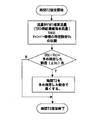
- FIG. 9 is a flow chart showing the procedure of a control method for realizing the operation of the energy recovery system of the present invention.
- the operation control of the energy recovery device EPD
- the counter of the flow meter FM1 that measures the flow rate of the concentrated concentrated seawater supplied to the energy recovery device is reset.
- the flow meter FM1 may be replaced with the flow meter FM3.
- the counter of the flow meter FM4 that measures the supplied seawater flow rate to the energy recovery device is reset.
- the flow meter FM4 may be replaced with the flow meter FM2.
- the trapezoidal wave signal which drives each switching valve is input.
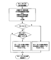
- FIG. 10 is a flow chart showing a procedure of setting time T2 shown in FIG.
- the time T2 setting compares the integrated flow rate of concentrated seawater with a predetermined ratio (for example, 80 to 90%) of the actual volume of the chamber, and when the integrated flow rate of concentrated seawater is smaller than the predetermined ratio of the actual volume of the chamber, The time T2 is set again. That is, as shown in FIG. 10, the absolute value of Vbi-Vc is defined in advance by comparing the integrated flow rate value (Vbi) of concentrated seawater obtained by the flow meter FM1 with a predetermined ratio (Vc) of the actual volume of the chamber.
- Vbi integrated flow rate value
- the time T2 is set without changing T2. If it is outside the predetermined range ( ⁇ Vo) (in the case of YES), the time T2 is lengthened at a predetermined rate to end the setting of the time T2 so as to increase the integrated flow rate value of the concentrated seawater.
- FIG. 11 is a flowchart showing a procedure of setting the maximum opening (LIMIT) of the switching valves VD-1 and VD-2 shown in FIG.
- the integrated flow rate value (Vbi) of concentrated seawater obtained by the flow meter FM1 and the integrated flow rate value (Vsi) of seawater obtained by the flow meter FM4 are compared, and whether Vbi-Vsi ⁇ 0 is satisfied? If NO (if Vbi is greater than or equal to Vsi), it is necessary to increase the supplied seawater flow rate, so the maximum opening (LIMIT) is increased by a predetermined degree.
- Vbi-Vsi when Vbi is less than Vsi, it is determined whether the absolute value of Vbi-Vsi is out of a predetermined range ( ⁇ Vi), and in the case of out of the range (in the case of YES)
- the maximum opening degree (LIMIT) of -1 and VD-2 is reduced by a previously defined degree (%) to finish setting the maximum opening degree, and when it is within the range (in the case of NO), switching valve VD-1 , And leave the maximum opening (LIMIT) of VD-2 as it is and complete the setting of the maximum opening.
- each switching valve determines the opening / closing order of each switching valve in advance, and the switching valve is opened / closed according to the order.
- the energy recovery system is used in an actual plant, many energy recovery systems are used simultaneously. In this case, there is a problem that it takes a lot of time to determine in advance the opening and closing order of the plurality of switching valves.
- it is easy to introduce an error in the determination of the opening and closing order of the plurality of switching valves and if there is an error, not only the function of the energy recovery device is lost, but the whole plant is adversely affected.
- the booster pump will be closed, which leads to failure of the booster pump.
- the supply flow rate to the reverse osmosis membrane separation device decreases, and the required fresh water flow rate can not be obtained.
- the present invention it is possible to interlock a plurality of switching valves by one type of input signal, it is not necessary to determine in advance the opening / closing order of a plurality of switching valves, which saves time and also a plurality of switchings. It is possible to avoid the occurrence of a problem due to an error in the opening and closing order of the valve. That is, the opening and closing states of the two switching valves installed in each chamber are indicated by the opening degree, and the relationship between the opening degree of the switching valve and the signal value to be input is represented using the switching valve setting value. In the embodiment described above, the relationship between the opening of the two sets of switching valves in two chambers, that is, the four switching valves and the input signal value is used.
- FIGS. 12A and 12B are graphs showing an input signal to a set of switching valves, a graph showing the operation of the switching valves, and an input signal with a phase difference.
- two switching valves VS and VD are used per chamber.
- the switching valve set values CC, DZ, MO, LI are set, and the degree of opening or closing of each switching valve VS, VD, that is, the opening degree is a trapezoidal wave input to each switching valve.
- the signal value IV changes, it changes according to the following equation. Formula of change in opening of switching valve VS ...
- the input signal here sets the form of the trapezoidal wave signal.
- the input signal is an input signal to the first pair of switching valves, a plurality of second switching valve pairs, a plurality of third switching valve pairs, etc. are provided with a phase difference in time.
- the phase difference in this case is set in advance.
- the present invention is applicable to a seawater desalination system that desalinates seawater by removing salinity from seawater, and an energy recovery apparatus suitably used for the seawater desalination system.
Landscapes
- Engineering & Computer Science (AREA)
- Water Supply & Treatment (AREA)
- Chemical & Material Sciences (AREA)
- Nanotechnology (AREA)
- Chemical Kinetics & Catalysis (AREA)
- Life Sciences & Earth Sciences (AREA)
- Hydrology & Water Resources (AREA)
- Environmental & Geological Engineering (AREA)
- Organic Chemistry (AREA)
- Separation Using Semi-Permeable Membranes (AREA)
Abstract
Description
エネルギー回収装置10においては、制御弁14の動作に伴って、2つのエネルギー回収チャンバー11,12内では、ピストン13,13の移動により送水ポンプ2からチェック弁モジュール15に通じた海水の導入と高圧の濃縮海水(リジェクト)を利用した海水の昇圧、吐出しを行う。
そのため、本件出願人は、特許文献1において円筒形長尺のチャンバーを圧力交換チャンバーとし、チャンバー内に複数の区画された流路を設けて逆浸透膜(RO膜)から排出される高圧の濃縮海水で直接海水を加圧する方式を採用することにより、ピストンの無い形態のエネルギー回収チャンバーを提案した。
一方、ピストンの無い形態のエネルギー回収チャンバーは、ピストンがないため同様の方法で給排水量を制御することができない。このため、海水と濃縮海水の給排水の切り替えを行う制御を別な手段、手法で行う必要がある。
本発明によれば、1つの入力信号で切換弁の開度および切換時間を調節することができるため、より的確に多数の切換弁の制御ができる。
本発明によれば、入力した信号値が一定値をとる時間を設けることにより各切換弁の開度を一定に保持する時間を調整することができる。
本発明によれば、入力される信号値とそれぞれの切換弁の開度との固有の関係を表す設定値に基づき切換弁を制御するため、設定値を変えることにより各切換弁の開度を修正しつつ制御することができる。
本発明によれば、第1流量計または第2流量計による積算を開始してから積算流量が所定値に到達したときに切換弁の切換を行うので、チャンバーへの濃縮海水の流入量が所定値に到達したタイミングで濃縮海水の流入を停止することができる。そのため、濃縮海水がエネルギー回収装置からブースターポンプに流入することがない。この場合、チャンバーへの濃縮海水の流入量は、第1流量計で測定した積算流量から求めることができる。また、チャンバーへ濃縮海水が流入するとチャンバー内の海水が排出(吐出)されるので、チャンバーからの海水の排出量(吐出量)を第2流量計で測定した海水の積算流量から求めることにより、チャンバーへの濃縮海水の流入量を求めることができる。
本発明によれば、チャンバーへの濃縮海水の流入量がチャンバーの実容積の所定の割合(例えば、80~90%)に到達したときに濃縮海水の流入を停止することができるため、濃縮海水がエネルギー回収装置からブースターポンプに流入することがない。上述したように、チャンバーへの濃縮海水の流入量は、第1流量計の積算流量から求めてもよいし、第2流量計の積算流量から求めてもよい。
本発明によれば、チャンバーへの濃縮海水の流入量の積算値とチャンバーからの濃縮海水の排出量の積算値とを比較し、チャンバーから排出される濃縮海水の流量を制御する。チャンバーから排出される濃縮海水の排出量は、チャンバーに流入する海水の流入量と等しいため、チャンバーからの濃縮海水の排出量を求めることによりチャンバーへの海水の流入量を求めることができる。したがって、チャンバーへの濃縮海水の流入量の積算値とチャンバーからの濃縮海水の排出量の積算値とを比較することによって、チャンバーへの濃縮海水の流入量とチャンバーへの海水の流入量のバランスをとることができる。このバランスを適正にとることにより、濃縮海水がエネルギー回収装置からブースターポンプに流入することがない。
また、上記より
・チャンバーへの海水の流入量の積算値とチャンバーから排出される海水の積算値を比較
・チャンバーへの濃縮海水の流入量の積算値とチャンバーから排出される海水の積算値を比較
・チャンバーへの海水の流入量の積算値とチャンバーからの濃縮海水の排出量の積算値を比較
することによっても、前記バランスを取ることができることは言うまでもなく、要は、チャンバーへ流入する流体とチャンバーから排出される流体の積算値を比較することにより、濃縮海水のブースターポンプへの流入を回避する。
ここでは、チャンバーへの濃縮海水の流入量の積算値とチャンバーからの濃縮海水の排出量の積算値を比較する場合について記載する。
なお、本発明によれば、前記切換弁の制御により、チャンバーへの海水の流入量とチャンバーへの濃縮海水の流入量を自在に調整することができる。
本発明によれば、チャンバーへの海水の流入量の積算値がチャンバーへの濃縮海水の流入量の積算値と等しく、もしくは、多くなるように切換弁を制御するので、濃縮海水がエネルギー回収装置からブースターポンプへ流入することがない。
複数のチャンバーにおいて、海水を吸入する工程と、吸入された海水を濃縮海水によって昇圧して吐出(排出)する工程とを繰り返すが、この場合、一つのチャンバーが海水吐出工程を終了したときに他のチャンバーが海水吐出工程を開始するように切換弁を制御すると、切換時に昇圧海水の脈動が起こる。そのため、本発明では、複数のチャンバーから昇圧された海水が同時に吐出されるように切換弁を制御し、すなわち複数のチャンバーの海水吐出工程を重複させることにより、昇圧海水の脈動を抑制することができる。
1)複数のチャンバーへの濃縮海水と海水の給排水の切り換えを正確なタイミングで行うことができるため、塩分濃度の高い海水を逆浸透膜分離装置に送ってしまうことがないので、脱塩率を低下させることなく逆浸透膜分離装置の性能を十分に発揮することができるとともに、逆浸透膜自体の交換周期を長くすることができる。
2)一つの入力信号を入力することにより複数の切換弁を連動して動作させることができるため、複数の切換弁の開閉順序を決める手間が省略でき、時間の節約になる。また、多数の切換弁の開閉順序を決める際に順序を誤って決めてしまうことがなくなり、装置の機能低下が回避できる。
3)複数のチャンバーから同時に昇圧海水を吐出(排出)する工程を含んでいるため、昇圧海水の流量および圧力の脈動が小さい。
4)チャンバーから排出される濃縮海水の排出量を制御することにより、チャンバーに流入する海水の流入量を制御することができるため、チャンバーから海水が必要以上に排出されることがない。
5)海水淡水化システムにおいて淡水の需要量が変化する場合に、逆浸透膜分離装置からエネルギー回収装置に供給される濃縮海水の流量が変化するが、この流量変化に速やかに追従することができる。
エネルギー回収装置10においては、切換装置20の動作に伴って、2つのエネルギー回収チャンバー11,12内では、濃縮海水と海水の界面が濃縮海水と海水の双方の圧力バランスによりチャンバー内を移動することにより送水ポンプ2からチェック弁モジュール15に通じた海水の導入と高圧の濃縮海水(リジェクト)を利用した海水の昇圧、吐出しを行う。
切換弁の開度(縦軸)と入力信号(横軸)との関係を図3に示す。図3に示すように、切換弁(VS-1,VS-2,VD-1,VD-2)に対する入力信号は-100(%)から+100(%)までの値をとり、縦軸に示す切換弁の開度は0から100までの範囲で変化する。すなわち切換弁VS-1,VS-2は全閉の0から全開の100の間で変化し、切換弁VD-1,VD-2は全閉の0から適宜設定する最大開度の間で変化する。
図3に示す4種の設定値MO,LI,CC、DZは、それぞれ以下のように決められる。すなわち、切換弁VS-1及びVS-2が全開(MAX OPENING)となるときの入力信号値の絶対値をMO、切換弁VD-1及びVD-2の最大開度(LIMIT)として設定する値をLI、両チャンバー11,12が連通している状態である両チャンバー連通域(CHAMBER CONNECT)の最大入力信号値又は最小入力信号値の絶対値をCC、切換弁VD-1及びVD-2の開度がゼロの領域(開度不感域と称する)(DEAD ZONE)であるときの最大入力信号値又は最小入力信号値の絶対値をDZとする。
図3から明らかなように、入力信号値が0であるときの縦軸を中心線として左右対称のグラフとなっており、図2に示す2組のチャンバー11,12に使用される4つの切換弁(VS-1,VS-2,VD-1,VD-2)について一つの入力信号で制御している。
各切換弁の開閉の度合いすなわち開度は、各切換弁に対して入力される台形波信号値IVの変化に伴い、それぞれ次のような式に従って変化する。
切換弁VS-1の開度変化の式・・・(100/(CC+MO))×(-IV+CC)
切換弁VS-2の開度変化の式・・・(100/(CC+MO))×(IV+CC)
切換弁VD-1の開度変化の式・・・(LI/(100-DZ))×(IV-DZ)
切換弁VD-2の開度変化の式・・・(LI/(100-DZ))×(-IV-DZ)
図4に入力信号値(input value)IVと時間との関係を示す台形波信号を示す。台形波の形状は時間T1と時間T2とにより構成され、台形波としての入力信号IVは、各切換弁に対して-100(%)から+100(%)の間の値を示す。
時間T1は、入力信号値IVを0~100%、100~0%、0~-100%、-100~0%に変化させる時間であり、時間T1を適宜設定することにより各切換弁の開閉に要する時間を調整することができる。
時間T2は、入力信号値IVが100%及び-100%に到達した後の保持時間であり、時間T2を適宜設定することにより各切換弁の開閉後の保持時間を調整することができる。
図5は、切換弁の開度(縦軸)と入力信号(横軸)との関係を示している。図5の縦軸には切換弁の開度を示すR(%),T(%),V(%)を便宜上左端に示す。また図5の横軸には入力信号値IVのS(%),U(%)を示す。各切換弁(VS-1,VS-2,VD-1,VD-2)は、入力信号に応じて、予め規定された設定値(MO,LI,CC、DZ)に基づき開度が変化する。
例えば、入力信号値が0%の場合は、VS-1,VS-2の開度はともにR%であり、VD-1,VD-2の開度はともに0%である。入力信号値がS%の場合は、VS-1の開度は0%になり、VS-2の開度はT%になり、VD-1,VD-2の開度はともに0%である。また、入力信号値がU%の場合は、VS-1の開度は0%、VS-2の開度はV%であり、VD-1,VD-2の開度は0%である。入力信号値が100%の場合は、VS-1の開度は0%、VS-2の開度は全開(100%)であり、VD-1の開度は最大開度(LIMIT)であり、VD-2の開度は0%である。
入力信号値IVが0%~-100%と変化する場合、VS-1はMOとCCによって規定される開度から全開になり、VD-1は全閉であり、VS-2は開度が小さくなり全閉になり、VD-2は全閉からLIで規定される開度になる。入力信号値が-100%の場合、VS-1は全開であり、VD-1は全閉であり、VS-2は全閉であり、VD-2はLIで規定される開度を保持する。入力信号値IVが-100%~0%と変化する場合、VS-1は全開からMOとCCによって規定される開度になり、VD-1は全閉であり、VS-2は全閉からMOとCCによって規定される開度になり、VD-2はLIで規定される開度から全閉になる。
図7の上段のグラフに示すように、台形波の形状は時間T1と時間T2とにより構成され、台形波としての入力信号IVは、各切換弁に対して-100(%)から+100(%)の間の値を示す。時間T1は、入力信号値IVを0~100%、100~0%、0~-100%、-100~0%に変化させる時間であり、時間T1を適宜設定することにより各切換弁の開閉に要する時間を調整することができる。時間T2は、入力信号値IVが100%及び-100%に到達した後の保持時間であり、時間T2を適宜設定することにより各切換弁の開閉後の保持時間を調整することができる。
なお、ここで、前記チャンバー吸入海水流量とチャンバー排出濃縮海水流量が同一の変化をし、前記チャンバー吸入濃縮海水流量とチャンバー吐出海水流量が同一の変化をする。
入力信号が0のときエネルギー回収チャンバー11への吸入海水流量は0であり、入力信号値がU%(図5参照)になったとき、すなわち開度不感域(DEAD ZONE)を超えた時点でエネルギー回収チャンバー11への海水吸入を開始し、入力信号が+100になる時点でエネルギー回収チャンバー11への海水吸入は一定流量となり、入力信号が+100の間(時間T2の間)一定流量を保持する。入力信号が+100から減り始めるとエネルギー回収チャンバー11への海水吸入も減少し、入力信号値がU%になると海水吸入を終了する。入力信号値が-U%になるまで吸入海水流量は0であり、入力信号値が-U%より減少するとエネルギー回収チャンバー12への海水吸入を開始し、入力信号が-100になる時点でエネルギー回収チャンバー12への海水吸入は一定流量となり、入力信号が-100の間(時間T2の間)一定流量を保持する。入力信号が-100から増え始めるとエネルギー回収チャンバー12への海水吸入も減少し、入力信号値が-U%の時点で海水吸入を終了する。入力信号値が-U%から0になるまで吸入海水流量は0である。入力信号値が0から次に0になるまでのサイクルが1/2周期である。
入力信号値が0であるときは、エネルギー回収チャンバー11,12へ同時に濃縮海水が吸入され、入力信号値がS%になった時点でエネルギー回収チャンバー11への縮海水吸入は停止するが、エネルギー回収チャンバー12へは継続して濃縮海水が吸入される。切換弁VS-2の開度が最大開度になった時点で濃縮海水吸入量は一定となり、その後入力信号値が+100%である間(時間T2の間)濃縮海水吸入量は一定である。入力信号値が+100%から減少しはじめ切換弁VS-2の開度が最大開度である時点まではチャンバー12への濃縮海水吸入量は一定であり、その後吸入量は減少するが、入力信号値がS%になった時点でチャンバー11への濃縮海水の吸入が開始する。入力信号値がS%から-S%までの間は両チャンバー11,12に濃縮海水が吸入される。入力信号値が-S%でチャンバー12への濃縮海水吸入は停止するがエネルギー回収チャンバー11へは継続して濃縮海水が吸入される。切換弁VS-1の開度が最大開度になった時点で濃縮海水吸入量は一定となり、その後入力信号値が-100%である間(時間T2の間)濃縮海水吸入量は一定である。入力信号値が-100%から増加しはじめ切換弁VS-1の開度が最大開度である時点まではチャンバー11への濃縮海水吸入量は一定であり、その後吸入量は減少するが、入力信号値が-S%になった時点でチャンバー12への濃縮海水の吸入が開始する。入力信号値が-S%から0(+S%)までの間は両チャンバー11,12に濃縮海水が吸入される。入力信号値と各チャンバーへの濃縮海水の吸入状態は以上のような態様をとるが、図示されるように、チャンバーへの吸入濃縮海水流量は常に一定である。
(1)入力信号値IVの範囲を図6に示すように±S%、±U%、±100%で区切り、10通りで表す。
入力信号値IVが-S%~+S%の場合と入力信号値IVが+S%~-S%の場合において、濃縮海水と海水の接触界面は、同時に海水昇圧の工程になる。
これにより、エネルギー回収装置からブースターポンプに吐出される昇圧海水の脈動の抑制が可能となる。
(2)濃縮海水排出側(海水供給側)の切換弁VD-1,VD-2の最大開度の設定(制御)は、エネルギー回収装置へ供給する濃縮海水の積算流量≦エネルギー回収装置へ供給する海水の積算流量になるようにし、かつ、両積算流量の差も調節可能にする。
これにより、下記を実現する。
1)濃縮海水がエネルギー回収装置からブースターポンプに流入しない。
2)海水がエネルギー回収装置から必要以上に排出されない。
また、切換弁VD-1,VD-2の最大開度(LIMIT)を適宜設定することにより、エネルギー回収装置へ供給する濃縮海水の積算流量とエネルギー回収装置へ供給する海水の積算流量を自在に調整することが可能となる。
(1)各切換弁の切換時間の調整について
ここで各切換弁の切換時間とは図7及び図8に示す時間T1及び時間T2を指す、すなわち入力信号の台形波の形状を決定する要素である。
図7及び図8の上段のグラフに示すように、1/2周期において入力信号値が0%と+100%との間の値をとるとき、すなわち時間T1のときには、いずれかの切換弁が開閉動作を行っている時間である。この時間T1の間は、チャンバーに吸入(供給)される濃縮海水(または海水)の流量は一定ではないため、この一定でない流量に基づいてチャンバーが濃縮海水(または海水)で満水になる時間を予測することはできない。
一方、入力信号値が+100%の値を保持する時間、すなわち時間T2のときには、いずれの切換弁も開又は閉の状態にあって開閉動作を行うことはない。そのため、チャンバーに吸入(供給)される濃縮海水(または海水)の流量は一定であり、この一定流量に基づけばチャンバーが濃縮海水(または海水)で満水になる時間を予測できる。次の1/2周期においても同様である。
i)切換弁の切換時間T1を所定値に設定する。
ii)時間T2は、エネルギー回収チャンバーの容積と濃縮海水の流入量から、予めエネルギー回収チャンバーが濃縮海水で満水になるまでの時間を計算して設定する。
この際、濃縮海水のブースターポンプへの流入を確実に回避するために、例えば、計算時にエネルギー回収チャンバーの容積を実容積よりも数~数十%小さくするか、もしくは算出された時間の数~数十%短い時間に設定するなどの方法が挙げられる。
i)切換弁の切換時間T1を所定値に設定する。
ii)時間T2は、流量計FM1にて測定される濃縮海水流量に応じて自動で設定する。
すなわち、切換弁VS-1もしくはVS-2が開き始めた時点から流量計FM1の測定値の積算を開始し、当該積算値がエネルギー回収チャンバーの実容積の所定の割合(80-90%)(初期設定値)に到達したら、切換弁VS-1もしくはVS-2が閉じるように入力信号値を変化させる。なお、流量計FM1にて測定される吸入濃縮海水流量と流量計FM3にて測定される吐出海水流量とは等しいので、流量計FM3を用いてもよい。
動作は以下のようになる。
図6における右最上段に示されるように切換弁VS-1が開き始めた時点からチャンバー11への濃縮海水流量の積算を開始し、積算値がエネルギー回収チャンバーの実容積の所定の割合(80-90%)に到達したら、時間T2を終了し切換弁VS-1を閉じる。
図6における左最上段に示されるようにVS-2が開き始めた時点からチャンバー12への濃縮海水流量の積算を開始し、積算値がエネルギー回収チャンバーの実容積の所定の割合(80-90%)に到達したら、時間T2を終了し切換弁VS-2を閉じる。
時間T2の次周期での増減量は予め設定しておいても良いし、エネルギー回収チャンバー容積との偏差量に応じて増減量を変化させても良い、すなわち偏差量が大きい場合は増減量を大きくし、偏差量が小さい場合は増減量を小さくする。
切換弁VD-1,VD-2の最大開度(LIMIT)を自動調節して、エネルギー回収チャンバーへの供給濃縮海水の水量と供給海水の水量のバランスをとる方法である。
図8の最下段のグラフにエネルギー回収チャンバーへの供給海水流量及びエネルギー回収チャンバーへの供給濃縮海水流量を示す。
エネルギー回収チャンバーへの供給海水流量についてみると、時間T1の間は、エネルギー回収チャンバーへの吸入海水流量は一定ではなく増減し、時間T2の間は、吸入海水流量は最大で一定量であり、切換弁VD-1およびVD-2が全閉となる入力信号値が0~U%の間及び0~-U%の間(図5参照)では、吸入海水流量は0になる。
一方、エネルギー回収チャンバーへの吸入濃縮海水流量は一定である。
ここで、エネルギー回収装置へ供給される濃縮海水がブースターポンプへ流入しない条件としては、各チャンバー内に導入,導出する濃縮海水の水量と海水の水量を同一にする必要がある。
エネルギー回収装置への供給海水流量の積算値≧エネルギー回収装置への供給濃縮海水流量の積算値
これにより、常に濃縮海水がブースターポンプへ流入することがない状態を維持できる。
また、エネルギー回収装置への供給濃縮海水のエネルギー(圧力、流量)が損失しないようにするため、エネルギー回収装置の供給濃縮海水側の切換弁VS-1,VS-2の開度は基本的に全開とする。
また、上記の条件にかかわらず、エネルギー回収装置への供給海水流量とエネルギー回収装置への供給濃縮海水流量を切換弁VD-1,VD-2の開度を制御することにより調整することも可能である。
図8にはさらに、入力信号の台形波、切換弁VS-1,VS-2の開閉動作、切換弁のVD-1,VD-2の開閉動作を示す。これらの動作は、図7において説明したとおりである。
1)1/2周期(A)において、入力信号値が0%(切換弁VS-1が開の状態)の時点から、エネルギー回収装置への吸入濃縮海水流量を測定する流量計FM1の測定値の積算を開始する。なお、流量計FM1にて測定される吸入濃縮海水流量と流量計FM3にて測定される吐出海水流量とは等しいので、流量計FM3を用いてもよい。
これと同時に、エネルギー回収装置への吸入海水流量を測定する流量計FM4の測定値の積算を開始する。なお、流量計FM4にて測定される吸入海水流量と流量計FM2にて測定される排出濃縮海水流量とは等しいので、流量計FM2を用いてもよい。
2)1/2周期(A)の終了時点で、吸入濃縮海水流量の積算および吸入海水流量の積算を終了する。このときの吸入濃縮海水流量の積算値は矩形状の面積Aになり、吸入海水流量の積算値は台形状の面積Bになる。次の1/2周期(B)においても同様に積算値を得る。
3)次に、吸入濃縮海水流量の積算値と吸入海水流量の積算値とを比較し、エネルギー回収装置への供給海水流量の積算値≧エネルギー回収装置への供給濃縮海水流量の積算値になるように、次の1/2周期(A)で切換弁VD-1,VD-2の開度を自動調整する。
すなわち、1/2周期(A)の積算値比較結果を次の1/2周期(A)に反映する。つまり、積算値比較結果を反映させて切換弁VD-2の最大開度(LIMIT)を調整(制御)する。
なお、切換弁VD-1,VD-2の最大開度(LIMIT)の増減量は、あらかじめ決めた値(設定値)を用いても良いし、積算値の比較結果により変化させても良い。つまり、積算値の差が大きければ、増減量を大きくし、積算値の差が小さければ増減量を小さくするなどの方法を用いても良い。
4)入力信号値が0から+100%に増加し再び100から0%に減少する間(または0から-100%に減少し再び-100から0%に増加する間)において、切換弁VS-1,VS-2の開き始めから閉じ終わりまでの、各々1/2周期間にて、上記1)~3)の制御を行う。
なお、手順3)における条件を確実に満たすために、エネルギー回収装置への供給濃縮海水流量の積算値に予め設定した係数を掛けた上で、上記の条件だしを行うこともありうる。
図9に示す態様においては、エネルギー回収装置(ERD)の運転制御を開始し、エネルギー回収装置への供給濃縮海水流量を測定する流量計FM1のカウンタをリセットする。なお、流量計FM1を流量計FM3に置き換えてもよい。また、エネルギー回収装置への供給海水流量を測定する流量計FM4のカウンタをリセットする。なお、流量計FM4を流量計FM2に置き換えてもよい。そして、各切換弁を駆動する台形波信号を入力する。入力信号値が0%であるか否かを判断し、入力信号値が0%の時点(両チャンバーに濃縮海水が供給されている状態)で濃縮海水の流量と海水の流量の積算を開始する。これらの流量の積算を入力信号値が再び0%になるまで行う。次に濃縮海水の積算流量とチャンバーの実容積の所定の割合(例えば80~90%)とを比較し、濃縮海水の積算流量がチャンバーの実容積の所定の割合よりも大きいか否かを判断し、YESの場合には時間T2を予め決めた割合で短くする。NOの場合には、時間T2設定(後述する)に移行し新たに時間T2を設定する。その後必要に応じて切換弁VD-1,VD-2の最大開度設定を行い、台形波信号入力に戻る。
時間T2設定は、濃縮海水の積算流量とチャンバーの実容積の所定割合(例えば80~90%)とを比較し、濃縮海水の積算流量がチャンバーの実容積の所定の割合よりも小さい場合に、時間T2を改めて設定する。すなわち、図10に示すように、流量計FM1により得られた濃縮海水の流量積算値(Vbi)とチャンバーの実容積の所定割合(Vc)とを比較し、Vbi-Vcの絶対値が予め規定した範囲(ΔVo)外か否かを判断し、範囲(ΔVo)内の場合(NOの場合)はT2を変更しないでそのままの時間T2を設定する。予め規定した範囲(ΔVo)外である場合(YESの場合)は、濃縮海水の積算流量値を増加させるように、時間T2を予め規定した割合で長くして時間T2の設定を終了する。
図11においては、流量計FM1により得られた濃縮海水の流量積算値(Vbi)と流量計FM4により得られた海水の流量積算値(Vsi)とを比較し、Vbi-Vsi<0であるか否かを判断し、NOの場合(VbiがVsiより多いか等しい場合)は、供給海水流量を増やす必要があるため、最大開度(LIMIT)を予め規定した度合いで大きくする。YESの場合(VbiがVsiより少ない場合)は、Vbi-Vsiの絶対値が予め規定した範囲(ΔVi)外か否かを判断し、範囲外の場合(YESの場合)には、切換弁VD-1,VD-2の最大開度(LIMIT)を予め規定した度合い(%)で小さくして最大開度設定を終了し、範囲内の場合(NOの場合)には、切換弁VD-1,VD-2の最大開度(LIMIT)をそのままにして最大開度設定を終了する。
図12A,12Bは、一組の切換弁に対する入力信号と切換弁の動作を示すグラフ及び位相差を持たせた入力信号を示す図である。
エネルギー回収チャンバー内の流体を動作させる目的においては、チャンバー1つ当たり2個の切換弁VS,VDを用いる。図12Aに示すように、切換弁の開閉設定値CC,DZ,MO,LIを設定し、各切換弁VS,VDの開閉の度合いすなわち開度は、各切換弁に対して入力される台形波信号値IVの変化に伴い、それぞれ次のような式に従って変化する。
切換弁VSの開度変化の式・・・(100/(CC+MO))×(IV+CC)
切換弁VDの開度変化の式・・・(LI/(100-DZ))×(-IV-DZ)
入力信号は、ここでは台形波信号の形態を設定する。
図12Bに示すように、前記入力信号が第1の切換弁のペアに対する入力信号だとすると、時間的に位相差をもたせて第2の切換弁のペア、第3の切換弁のペアというように複数の切換弁のペアに対して入力することにより、チャンバーが複数になっても複数組の切換弁を連動させることができる。この場合の位相差は予め設定しておく。
さらに、前述した実施形態のように、一つの入力信号で2個のチャンバーの2組の切換弁を連動して動作させるようにし、この入力信号を位相差を持たせて入力することも可能である。
2 送水ポンプ
3 高圧ポンプライン
4 エネルギー回収装置海水供給ライン
5 高圧ポンプ
6 ブースターポンプ海水供給ライン
7 ブースターポンプ
8 逆浸透膜分離装置
8a 逆浸透膜(RO膜)
9 濃縮海水ライン
10 エネルギー回収装置
11,12 エネルギー回収チャンバー
15 チェック弁モジュール
16 濃縮海水排出ライン
20 切換装置
21 制御装置
FM1,FM2,FM3,FM4 流量計
P1 濃縮海水ポート
P2 海水ポート
VS-1,VS-2,VD-1,VD-2 切換弁
Claims (11)
- ポンプによって昇圧した海水を逆浸透膜分離装置に通水して淡水と濃縮海水に分離して海水から淡水を生成する海水淡水化システムに設けられ、前記逆浸透膜分離装置から吐出される濃縮海水の圧力エネルギーを前記海水の一部を昇圧するエネルギーに利用するエネルギー回収装置において、
濃縮海水および海水を給排水して濃縮海水の圧力エネルギーによって海水を昇圧する複数のチャンバーと、
前記チャンバーに流入する海水または濃縮海水の流量を積算するために用いる第1流量計と、
前記チャンバーから排出される海水または濃縮海水の流量を積算するために用いる第2流量計と、
前記複数のチャンバーの各々に設置され、各チャンバーへの濃縮海水の流入と各チャンバーからの濃縮海水の排出を切り換える少なくとも1つの切換弁と、
前記第1流量計および/または前記第2流量計の流量に基づき前記チャンバーの積算流量を求めて該積算流量に基づいて前記複数のチャンバーの各切換弁を制御する制御装置とを備え、
前記制御装置は前記複数のチャンバーの各切換弁に単一の入力信号を入力して前記各切換弁を制御することを特徴とするエネルギー回収装置。 - 前記単一の入力信号によって前記各切換弁の開度および切換時間を制御可能であることを特徴とする請求項1記載のエネルギー回収装置。
- 前記単一の入力信号として台形波を用いることを特徴とする請求項1記載のエネルギー回収装置。
- 前記各切換弁の開度は、予め規定された設定値に基づき前記入力信号に対して変化するように設定されていることを特徴とする請求項1乃至3のいずれか1項に記載のエネルギー回収装置。
- 前記制御装置は、前記第1流量計または前記第2流量計による前記チャンバーの積算流量が所定値に到達したときに前記チャンバーの前記切換弁の切換を行うように制御することを特徴とする請求項1記載のエネルギー回収装置。
- 前記チャンバーの実容積の所定の割合から算定される値で前記切換弁の切換を行うことを特徴とする請求項5記載のエネルギー回収装置。
- 前記制御装置は、前記チャンバーへの濃縮海水の流入量の積算値と前記チャンバーからの濃縮海水の排出量の積算値とを比較して、前記チャンバーから排出される濃縮海水の流量を制御することを特徴とする請求項1に記載のエネルギー回収装置。
- 前記制御装置は、前記チャンバーへの海水の流入量の積算値が前記チャンバーへの濃縮海水の流入量の積算値と等しく、もしくは、多くなるように、前記切換弁を制御することを特徴とする請求項1記載のエネルギー回収装置。
- 前記制御装置は、複数のチャンバーから昇圧された海水を同時に排出する工程を含むように前記各切換弁を制御することを特徴とする請求項1記載のエネルギー回収装置。
- ポンプによって昇圧した海水を逆浸透膜分離装置に通水して淡水と濃縮海水に分離して海水から淡水を生成する海水淡水化システムに設けられ、前記逆浸透膜分離装置から吐出される濃縮海水の圧力エネルギーを前記海水の一部を昇圧するエネルギーに利用するエネルギー回収装置において、
濃縮海水および海水を給排水して濃縮海水の圧力エネルギーによって海水を昇圧する複数のチャンバーと、
前記複数のチャンバーの各々に設置され、各チャンバーへの濃縮海水の流入と各チャンバーからの濃縮海水の排出を切り換える少なくとも1つの切換弁と、
前記複数のチャンバーの各切換弁に単一の入力信号を入力して前記各切換弁を制御する制御装置とを備えたことを特徴とするエネルギー回収装置。 - ポンプによって昇圧した海水を逆浸透膜分離装置に通水して淡水と濃縮海水に分離して海水から淡水を生成する海水淡水化システムにおいて、
前記逆浸透膜分離装置から吐出される濃縮海水の圧力エネルギーを前記海水の一部を昇圧するのに利用する請求項1乃至10のいずれか1項に記載のエネルギー回収装置を備えたことを特徴とする海水淡水化システム。
Priority Applications (3)
| Application Number | Priority Date | Filing Date | Title |
|---|---|---|---|
| CN201480013634.9A CN105073230B (zh) | 2013-03-11 | 2014-02-25 | 海水淡化系统以及能量回收装置 |
| JP2015505376A JP6368705B2 (ja) | 2013-03-11 | 2014-02-25 | 海水淡水化システムおよびエネルギー回収装置 |
| US14/774,011 US9957169B2 (en) | 2013-03-11 | 2014-02-25 | Seawater desalination system and energy recovery apparatus |
Applications Claiming Priority (2)
| Application Number | Priority Date | Filing Date | Title |
|---|---|---|---|
| JP2013048371 | 2013-03-11 | ||
| JP2013-048371 | 2013-03-11 |
Publications (1)
| Publication Number | Publication Date |
|---|---|
| WO2014141872A1 true WO2014141872A1 (ja) | 2014-09-18 |
Family
ID=51536547
Family Applications (1)
| Application Number | Title | Priority Date | Filing Date |
|---|---|---|---|
| PCT/JP2014/054493 Ceased WO2014141872A1 (ja) | 2013-03-11 | 2014-02-25 | 海水淡水化システムおよびエネルギー回収装置 |
Country Status (4)
| Country | Link |
|---|---|
| US (1) | US9957169B2 (ja) |
| JP (1) | JP6368705B2 (ja) |
| CN (1) | CN105073230B (ja) |
| WO (1) | WO2014141872A1 (ja) |
Cited By (2)
| Publication number | Priority date | Publication date | Assignee | Title |
|---|---|---|---|---|
| JP2016221446A (ja) * | 2015-05-29 | 2016-12-28 | 株式会社日立製作所 | 水処理システム |
| JP2025064365A (ja) * | 2023-10-06 | 2025-04-17 | 株式会社電業社機械製作所 | エネルギー回収装置 |
Families Citing this family (10)
| Publication number | Priority date | Publication date | Assignee | Title |
|---|---|---|---|---|
| GB201813792D0 (en) * | 2018-08-23 | 2018-10-10 | Davies Philip Andrew | Desalination system and method |
| CN110182903B (zh) * | 2019-07-03 | 2024-07-26 | 南京惟新环保装备技术研究院有限公司 | 应用于海水淡化系统的双联能量回收器及能量回收系统 |
| CN111634975B (zh) * | 2020-06-02 | 2023-10-27 | 上海瑜科环境工程有限公司 | 节能型海水淡化工艺 |
| GB202017512D0 (en) | 2020-11-05 | 2020-12-23 | Univ Birmingham | Desalination system and method |
| US11502322B1 (en) | 2022-05-09 | 2022-11-15 | Rahul S Nana | Reverse electrodialysis cell with heat pump |
| US11502323B1 (en) | 2022-05-09 | 2022-11-15 | Rahul S Nana | Reverse electrodialysis cell and methods of use thereof |
| US12040517B2 (en) | 2022-11-15 | 2024-07-16 | Rahul S. Nana | Reverse electrodialysis or pressure-retarded osmosis cell and methods of use thereof |
| US11855324B1 (en) | 2022-11-15 | 2023-12-26 | Rahul S. Nana | Reverse electrodialysis or pressure-retarded osmosis cell with heat pump |
| JP2025538227A (ja) | 2022-11-15 | 2025-11-26 | エス ナナ,ラフル | 逆電気透析または圧力遅延浸透セルおよびその使用方法 |
| CN116272373B (zh) * | 2023-04-06 | 2023-09-15 | 广东海洋大学 | 一种磁力驱动式余压能回收装置及其海水淡化系统 |
Citations (4)
| Publication number | Priority date | Publication date | Assignee | Title |
|---|---|---|---|---|
| JPH08294619A (ja) * | 1995-04-27 | 1996-11-12 | Nikkiso Co Ltd | 往復動ポンプ式動力回収システム |
| JP2003144856A (ja) * | 2001-11-12 | 2003-05-20 | Sasakura Engineering Co Ltd | 逆浸透膜装置用エネルギー回収装置 |
| JP2012192324A (ja) * | 2011-03-15 | 2012-10-11 | Toshiba Corp | 海水淡水化装置 |
| JP2013139012A (ja) * | 2012-01-06 | 2013-07-18 | Ebara Corp | 海水淡水化システムおよびエネルギー回収装置 |
Family Cites Families (5)
| Publication number | Priority date | Publication date | Assignee | Title |
|---|---|---|---|---|
| CN103623702B (zh) | 2009-05-15 | 2017-08-25 | 株式会社荏原制作所 | 海水淡化系统及能量交换腔室 |
| CN101581328A (zh) * | 2009-05-31 | 2009-11-18 | 王世昌 | 反渗透海水淡化系统用联合活塞自增压能量回收泵 |
| JP5085675B2 (ja) * | 2010-03-12 | 2012-11-28 | 株式会社東芝 | 海水淡水化システム |
| EP2548847A1 (en) * | 2010-03-15 | 2013-01-23 | Toray Industries, Inc. | Method for producing fresh water |
| AU2011333447A1 (en) * | 2010-11-26 | 2013-06-20 | Abb Research Ltd. | System and method for operation of reverse osmosis units |
-
2014
- 2014-02-25 CN CN201480013634.9A patent/CN105073230B/zh not_active Expired - Fee Related
- 2014-02-25 JP JP2015505376A patent/JP6368705B2/ja not_active Expired - Fee Related
- 2014-02-25 US US14/774,011 patent/US9957169B2/en active Active
- 2014-02-25 WO PCT/JP2014/054493 patent/WO2014141872A1/ja not_active Ceased
Patent Citations (4)
| Publication number | Priority date | Publication date | Assignee | Title |
|---|---|---|---|---|
| JPH08294619A (ja) * | 1995-04-27 | 1996-11-12 | Nikkiso Co Ltd | 往復動ポンプ式動力回収システム |
| JP2003144856A (ja) * | 2001-11-12 | 2003-05-20 | Sasakura Engineering Co Ltd | 逆浸透膜装置用エネルギー回収装置 |
| JP2012192324A (ja) * | 2011-03-15 | 2012-10-11 | Toshiba Corp | 海水淡水化装置 |
| JP2013139012A (ja) * | 2012-01-06 | 2013-07-18 | Ebara Corp | 海水淡水化システムおよびエネルギー回収装置 |
Cited By (4)
| Publication number | Priority date | Publication date | Assignee | Title |
|---|---|---|---|---|
| JP2016221446A (ja) * | 2015-05-29 | 2016-12-28 | 株式会社日立製作所 | 水処理システム |
| US10434472B2 (en) | 2015-05-29 | 2019-10-08 | Hitachi, Ltd. | Water treatment system |
| JP2025064365A (ja) * | 2023-10-06 | 2025-04-17 | 株式会社電業社機械製作所 | エネルギー回収装置 |
| JP7792386B2 (ja) | 2023-10-06 | 2025-12-25 | 株式会社電業社機械製作所 | エネルギー回収装置 |
Also Published As
| Publication number | Publication date |
|---|---|
| CN105073230B (zh) | 2017-07-04 |
| JP6368705B2 (ja) | 2018-08-01 |
| CN105073230A (zh) | 2015-11-18 |
| JPWO2014141872A1 (ja) | 2017-02-16 |
| US20160016826A1 (en) | 2016-01-21 |
| US9957169B2 (en) | 2018-05-01 |
Similar Documents
| Publication | Publication Date | Title |
|---|---|---|
| WO2014141872A1 (ja) | 海水淡水化システムおよびエネルギー回収装置 | |
| EP2838642B1 (en) | Reverse osmosis system with energy recovery devices | |
| JP5361928B2 (ja) | 海水淡水化装置およびその制御方法 | |
| KR101383014B1 (ko) | 압력조절 정삼투 방법 및 장치 | |
| US9387440B2 (en) | Desalination system with energy recovery and related pumps, valves and controller | |
| KR20190104042A (ko) | 역삼투 또는 나노여과에 의한 수처리 시스템 및 방법 | |
| JP6737661B2 (ja) | 逆浸透膜処理システム及び逆浸透膜処理システムの運転方法 | |
| JP6026133B2 (ja) | 海水淡水化システムおよびエネルギー回収装置 | |
| CN102399029A (zh) | 膜过滤系统 | |
| US10532321B2 (en) | Seawater desalination system and energy recovery device | |
| US9694323B2 (en) | Energy recovery apparatus | |
| EP3841066B1 (en) | Desalination system and method | |
| JP2012192324A (ja) | 海水淡水化装置 | |
| JP2019171320A (ja) | 淡水化システム | |
| WO2018047156A1 (en) | Method and system for liquid treatment | |
| KR20230129387A (ko) | 담수화 시스템과 방법 | |
| DK2368624T3 (en) | Plant and method of treatment of a liquid by means of reverse osmosis. | |
| CN203112553U (zh) | 一种反渗透膜闭路循环装置 | |
| US20150321928A1 (en) | Fresh water generation method (as amended) | |
| JP2013192971A (ja) | 動力回収bwroシステムおよび動力回収方法 | |
| JP2017221877A (ja) | 逆浸透膜分離装置 | |
| JP7303861B2 (ja) | 膜ろ過装置 | |
| JP2026027545A (ja) | 水ろ過システムにおけるスケール形成を管理するための技術及びこの技術を実装する逆浸透(ro)及びナノろ過(nf)システム | |
| KR102082802B1 (ko) | 고압펌프 가동률을 이용한 하수재이용 및 정수처리 ro 시스템의 제어 방법 | |
| Nam et al. | Evaluation on cleaning efficiency and membrane fouling by permeation coefficient and concentration polarization factor in pilot-scale SWRO processes |
Legal Events
| Date | Code | Title | Description |
|---|---|---|---|
| WWE | Wipo information: entry into national phase |
Ref document number: 201480013634.9 Country of ref document: CN |
|
| 121 | Ep: the epo has been informed by wipo that ep was designated in this application |
Ref document number: 14763553 Country of ref document: EP Kind code of ref document: A1 |
|
| ENP | Entry into the national phase |
Ref document number: 2015505376 Country of ref document: JP Kind code of ref document: A |
|
| WWE | Wipo information: entry into national phase |
Ref document number: 14774011 Country of ref document: US |
|
| NENP | Non-entry into the national phase |
Ref country code: DE |
|
| 122 | Ep: pct application non-entry in european phase |
Ref document number: 14763553 Country of ref document: EP Kind code of ref document: A1 |